EP1032913B1 - Video encoding device - Google Patents
Video encoding deviceDownload PDFInfo
- Publication number
- EP1032913B1 EP1032913B1EP98957108.8AEP98957108AEP1032913B1EP 1032913 B1EP1032913 B1EP 1032913B1EP 98957108 AEP98957108 AEP 98957108AEP 1032913 B1EP1032913 B1EP 1032913B1
- Authority
- EP
- European Patent Office
- Prior art keywords
- processor
- resolution
- video
- controller
- data
- Prior art date
- Legal status (The legal status is an assumption and is not a legal conclusion. Google has not performed a legal analysis and makes no representation as to the accuracy of the status listed.)
- Expired - Lifetime
Links
- 230000033001locomotionEffects0.000claimsdescription99
- 238000011161developmentMethods0.000claimsdescription2
- 230000002708enhancing effectEffects0.000claims1
- 238000012545processingMethods0.000description81
- 238000003860storageMethods0.000description57
- 238000000034methodMethods0.000description44
- 238000012546transferMethods0.000description27
- 238000004891communicationMethods0.000description6
- 230000006835compressionEffects0.000description5
- 238000007906compressionMethods0.000description5
- 239000011159matrix materialSubstances0.000description5
- 230000003287optical effectEffects0.000description4
- 239000004065semiconductorSubstances0.000description4
- 230000003247decreasing effectEffects0.000description3
- 238000001914filtrationMethods0.000description3
- 238000013139quantizationMethods0.000description3
- 238000013459approachMethods0.000description2
- 230000005540biological transmissionEffects0.000description2
- 238000006243chemical reactionMethods0.000description2
- 238000001816coolingMethods0.000description2
- 230000001360synchronised effectEffects0.000description2
- 238000001514detection methodMethods0.000description1
- 238000004519manufacturing processMethods0.000description1
- 230000000873masking effectEffects0.000description1
- 238000007781pre-processingMethods0.000description1
- 238000005549size reductionMethods0.000description1
- 230000002123temporal effectEffects0.000description1
- 238000012956testing procedureMethods0.000description1
- 238000012549trainingMethods0.000description1
- 239000013598vectorSubstances0.000description1
Images


Classifications
- H—ELECTRICITY
- H04—ELECTRIC COMMUNICATION TECHNIQUE
- H04N—PICTORIAL COMMUNICATION, e.g. TELEVISION
- H04N19/00—Methods or arrangements for coding, decoding, compressing or decompressing digital video signals
- H04N19/50—Methods or arrangements for coding, decoding, compressing or decompressing digital video signals using predictive coding
- H04N19/503—Methods or arrangements for coding, decoding, compressing or decompressing digital video signals using predictive coding involving temporal prediction
- H04N19/51—Motion estimation or motion compensation
- H04N19/53—Multi-resolution motion estimation; Hierarchical motion estimation
- H—ELECTRICITY
- H04—ELECTRIC COMMUNICATION TECHNIQUE
- H04N—PICTORIAL COMMUNICATION, e.g. TELEVISION
- H04N19/00—Methods or arrangements for coding, decoding, compressing or decompressing digital video signals
- H04N19/42—Methods or arrangements for coding, decoding, compressing or decompressing digital video signals characterised by implementation details or hardware specially adapted for video compression or decompression, e.g. dedicated software implementation
- H04N19/423—Methods or arrangements for coding, decoding, compressing or decompressing digital video signals characterised by implementation details or hardware specially adapted for video compression or decompression, e.g. dedicated software implementation characterised by memory arrangements
- H—ELECTRICITY
- H04—ELECTRIC COMMUNICATION TECHNIQUE
- H04N—PICTORIAL COMMUNICATION, e.g. TELEVISION
- H04N19/00—Methods or arrangements for coding, decoding, compressing or decompressing digital video signals
- H04N19/42—Methods or arrangements for coding, decoding, compressing or decompressing digital video signals characterised by implementation details or hardware specially adapted for video compression or decompression, e.g. dedicated software implementation
- H04N19/43—Hardware specially adapted for motion estimation or compensation
- H—ELECTRICITY
- H04—ELECTRIC COMMUNICATION TECHNIQUE
- H04N—PICTORIAL COMMUNICATION, e.g. TELEVISION
- H04N19/00—Methods or arrangements for coding, decoding, compressing or decompressing digital video signals
- H04N19/42—Methods or arrangements for coding, decoding, compressing or decompressing digital video signals characterised by implementation details or hardware specially adapted for video compression or decompression, e.g. dedicated software implementation
- H04N19/436—Methods or arrangements for coding, decoding, compressing or decompressing digital video signals characterised by implementation details or hardware specially adapted for video compression or decompression, e.g. dedicated software implementation using parallelised computational arrangements
Definitions
- the present inventionrelates to video encoding devices in general and to single chip video encoding devices, in particular.
- Methods for encoding an audio-visual signalare known in the art. According to these methods, a video signal is digitized, analyzed and encoded in a compressed manner. These methods are implemented in computer systems, either in software, hardware or a combined software-hardware form.
- Most hardware encoding systemsconsist of a set of semiconductor circuits, which are arranged on a large circuit board.
- State of the art encoding systemsinclude a single semiconductor circuit, which is based on a high power processor.
- FIG. 1is a schematic illustration of a video encoding circuit, referenced 10, which is known in the art.
- Circuit 10includes a motion estimation processor 12, a motion estimation memory 14 connected to the motion estimation processor 12, a RISC processor 16 connected to the motion estimation processor 12 and an image buffer 18, connected to RISC processor 16.
- RISC processor 16transfers a portion of video signal from image buffer 18 to memory unit 14.
- Motion estimation processor 12analyzes the motion of the video signal.
- Motion estimation processor 12utilizes memory unit 14 as a storage area for the video signal portion which is currently processed by it.
- the motion estimation processor 12completed analyzing the motion of a video signal portion, it transfers the results of the motion estimation analysis to the RISC processor 16.
- the RISC processor 16performs all other processing and encoding tasks which the video signal has to undergo, such as discrete COSINE transform (DCT), quantization, entropy encoding, bit-stream production and the like.
- the RISC processor 16utilizes the image buffer 18 as a storage area for the video signal portion which is currently processed by it, and as a temporary storage for its computational purposes.
- each of the processing units 12 and 16have a separate storage area. Accordingly, each of the processed portions of video signal, such as and ISO/IEC 13818 (MPEG-2) macro-blocks, have to be transferred to both memory unit 14 and image buffer 18. RISC processor 16 has to access image buffer 18 for the same data, each time this data is required. Such Retrieval of large data blocks, many times, greatly increases data traffic volume over the encoding system data transmission lines.
- circuit 10is able to execute all processing and encoding tasks in a serial manner, thereby capable of processing only a single macro-block at a time, requiring high operational processor frequencies.
- Circuit 10receives a macro-block, processes it and produces an encoded bit-stream. Internally, the RISC processor 16 operates in the same manner.
- circuit 10has a direct affect over the heat produced by it, thereby requiring large cooling elements as well as massive cooling devices such as fans and the like.
- Methods for estimating motion in a video signalare known in the art. According to these methods a frame is compared with previous frames. The difference between the frames is used to estimate a level of motion. These methods analyze a frame and map it, thereby indicating areas in frame which have no motion over previous frames and areas in the frame which are assigned with a motion level.
- each pixel in the search areais analyzed.
- This methodrequires a vast number of estimation operations and is thereby extremely resource consuming.
- This methodis also called a full exhaustive search.
- the search areais scanned in a center weighted manner, which can be logarithmic, and the like, whereby the center of the search area is scanned thoroughly at full resolution and the rest of the search area is scanned at lower resolution. Areas which detected as having some motion, in the low resolution search, are scanned again in full resolution. This reduces the overall number of estimation operations.
- Fig. 2is a schematic illustration of a DSP processor, referenced 50, which is known in the art.
- DSP processor 50is of a single instruction multiple data (SIMD) type machine. It includes a plurality of identical processing units (P.U.) 52, 56, 60, 64, 68 and 72, and a random access memory (RAM) 61. RAM 61 is divided into segments 54, 58, 62, 66, 70 and 74.
- SIMDsingle instruction multiple data
- Each memory segmentis exclusively assigned and connected to a processing unit, whereas RAM segment units 54, 58, 62, 66, 70 and 74 are assigned to and connected to processing units (P.U.) 52, 56, 60, 64, 68 and 72, respectively.
- P.U.processing units
- This structurehas several disadvantages.
- One disadvantage of such machineis that the same operation is performed by all of the processing units at same time.
- SIMD machineAnother disadvantage of the SIMD machine is that the data is not shared among the processing units. For example, processing unit 56 can access data contained in RAM segment 66 via processing unit 64 only. It cannot do so directly. It will be appreciated by those skilled in the art that such a configuration is inefficient.
- a further disadvantageis that individual operations that vary for different data items can not be efficiently performed by an SIMD machine.
- the programming of such operations into the processing units,is very difficult.
- Such individual operationscan be only performed in serial manner, while masking all irrelevant data, resulting in shutting off most of the processing units.
- the utilization of the hardware resources in an SIMD machine during such programming operationsis very low, and performance of the machine are dramatically decreased.
- Another disadvantagerelates to the interconnection structure between the processing units. It will be appreciated that, a processing unit within an SIMD machine is connected to a limited number of neighboring processing units. Hence communication between such a processing unit and a processing unit not connected thereto, is often a complex operation.
- Bit-stream processing and generationin a conventional encoding circuit, is performed by a general purpose processor.
- Bit-stream generationrequires some specific operations, which can not be performed efficiently by a general purpose processor.
- a general purpose processoruses a small portion of its processing resources, while shutting off rest of them. Therefore, the disadvantage is that the resources of such processor are not utilized efficiently.
- Patent publication US 5 610 658discloses an amount-of-movement detection device which is capable of detecting the amount of movement with a high degree of accuracy when the amount of movement of an image is detected by a hierarchical block matching method.
- Image data of plural hierarchies having different resolutions from each otheris formed from an input image.
- Image data of a higher hierarchyhas a lower resolution and is formed from image data input at two separate points in time.
- a video encoding systemincluding a video source providing multiple frame video signal, a memory unit, a compressed data interface, a host interface and a video encoding device, connected to the video source, the memory unit and the host interface.
- the video encoding deviceincludes a video input processor, for receiving the video signal, a global controller, for controlling the global operation of the video encoding device, connected to the video input processor, a motion estimation processor, connected to the global controller, a digital signal processor, connected to the global controller and the motion estimation processor, and a bit-stream processor connected to the digital signal processor and the global controller and the compressed data interface.
- the global controllerstores encoding commands received from the host interface thereby programming the video input processor, the motion estimation processor, the digital signal processor and the bit-stream processor.
- the video input processorreceives and stores the video signal in the memory unit.
- the motion estimation processorretrieves the video signal from the memory unit, generates motion analysis of the video signal, stores the motion analysis in the memory unit and provides the motion analysis to the digital signal processor.
- the digital signal processorprocesses the video signal according to the motion analysis, thereby producing an encoding commands sequence and encoded data.
- the bit-stream processorproduces an encoded video signal according to the encoding command sequence and the encoded data.
- At least one of the video input processor, the motion estimation processor, the digital signal processor and the bit-stream processoris directly connected to the memory unit.
- At least one of the video input processor, the motion estimation processor, the digital signal processor and the bit-stream processoris connected to the memory unit via the global controller.
- the motion estimation processor, the digital signal processor and the bit-stream processorcan operate in parallel, whereas the motion estimation processor operates on a macro-block i, the digital signal processor operates on a macro-block j and the bit-stream processor operates on a macro-block k, wherein i>j>k.
- the entire video encoding devicein constructed on a monolithic semiconductor.
- the motion estimation processorincludes a controller and a plurality of resolution processors, connected to the controller.
- the plurality of resolution processorsanalyze the development of the video signal in time, thereby producing motion analysis.
- the controllercontrols the plurality of resolution processors.
- the plurality of resolution processorsinclude at least one low resolution processor, for producing low resolution motion analysis, at least one full resolution processor, for producing full resolution motion analysis and at least one hyper resolution processor, for producing hyper resolution motion analysis.
- At least one of the least one low resolution processorreduces the resolution of a selected frame before producing the low motion analysis and at least one of the least one hyper resolution processors, enhances the resolution of a selected frame before producing the hyper resolution motion analysis.
- the plurality of resolution processorsinclude at least one full resolution processor, for producing full resolution motion analysis.
- the one full resolution processorprocesses the selected frame according to the low resolution motion analysis.
- the plurality of resolution processorsinclude at least one hyper resolution processor, for producing hyper resolution motion analysis, wherein at least one of the hyper resolution processors, processes a selected frame according to the full resolution motion analysis.
- the digital signal processorincludes a DSP controller, a plurality of processing units, for processing the multiple frame video digital signal, connected to the DSP controller, and at least one storage unit. Each of the processing units is connected to at least one of the storage units.
- the DSP controllercontrols the plurality of processing units.
- Each of the processing unitsis operative to access any storage address of any of the storage units, connected thereto.
- Each of the processing unitsis capable of operating according to a different program command.
- Each of the processing unitsoperates on a different portion of data.
- a video cameraincluding an optical assembly, a light sensitive device, and the video encoding device, connected to the light sensitive device.
- the present inventionovercomes the disadvantages of the prior art by providing a novel approach to video compression processing and a novel structure for a device, according to this approach.
- the device according to the inventionis a massively parallel digital video processor designed, for the purpose of real-time video encoding, like MPEG.
- This devicecan be incorporated in a single chip, and installed in digital camcorders, recordable digital video disk (DVD), PC and workstation multimedia, educational and training systems, video conferencing, broadcast equipment, security, content creation/authoring/video editing equipment, and the like.
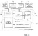
- FIG. 3is a schematic illustration of a video encoding device, generally referenced 100, constructed and operative in accordance with a preferred embodiment of the invention.
- Device 100includes a video input processor 106, a motion estimation processor 108, a digital signal processor 104, a bit-stream processor 102 and a global controller 110.
- the video input processor 106is connected to the global controller 110.
- the motion estimation processor 108is connected to the global controller 110 and to the digital signal processor 104.
- the digital signal processor 104is connected to the global controller 110 and to the bit-stream processor 102, which is also connected to the global controller 110.
- the bit-stream processor 102is further connected to a compressed data interface 128.
- the global controller 110is further connected to a host interface 120 and to a memory unit 122.
- the input of the video input processor 106is further connected to a digital video source (not shown) via a digital video interface 124.
- a hostis typically a user interface which is operative to receive commands, operational parameters, and the like, from a user or a supervising system and also to provide to the user information received from device 100.
- Device 100operates in two modes: a programming mode and an operational mode. Device 100 is operative to run according to both modes at the same time.
- a programming modean external host transfers the data and control parameters to the global controller 110, via the host interface 120.
- the global controller 110can transfer the data and control signals to the video input processor 106, motion estimation processor 108, digital signal processor 104 and bit-stream processor 102.
- the video input processor 106captures motion video signal from an external video source via the digitized video interface 124. Video input processor 106 also performs preprocessing of the video signal, such as spatial filtering, noise reduction, image quality improvement, image size adjustment, and the like, color format conversion, and the like, thereby producing preprocessed video data.
- Video input processor 106accumulates the preprocessed video data into data blocks and transfers them to the global controller 110.
- Global controller 110stores the data blocks in memory unit 122.
- the deviceoperates under MPEG-2 video compression standard.
- a data blockrepresents an MPEG-2 macro-block, which is a sixteen by sixteen [16x16] matrix of luminance pixels and two, four or eight, eight by eight [8 ⁇ 8] matrices of chrominance pixels, as defined by the MPEG-2 standard.
- a reference framerepresents a picture which is compared versus current picture during the motion estimation.
- the global controller 110retrieves a current picture macro-block and reference picture macro-blocks from the memory unit 122 and loads them to the motion estimation processor 108.
- Motion estimation processor 108compares the current picture macro-block with the respective reference frame macro-blocks, thereby producing an estimation of the motion of the current picture macro-block.
- the motion estimation processor 108uses this estimation to remove temporal redundancy of the video signal, as will be described in detail hereinbelow.
- the motion estimation processor 108transfers the resulting motion estimation data to the global controller 110.
- Motion estimation processor 108also transfers the current picture macro-block and the corresponding reference frames macro-blocks to the digital signal processor 104.
- Digital signal processor 104executes procedures which are intended to remove the spatial redundancy of the video signal, thereby producing a sequence of compression commands, as will be described in detail hereinbelow.
- This sequence of compression commandsincludes instruction as to which frame of the original video signal is to be compressed into an I-frame, a B-frame or a P-frame, and according to which reference frames.
- the digital signal processor 104transfers the sequence of compressed data to the bit-stream processor 102 and to the global controller 110.
- the bit-stream processor 102performs a series of encoding procedures, such as entropy encoding, and the like, as will be described in detail hereinbelow.
- the bit-stream processor 102compresses data into an MPEG-2 standard format data, in accordance with the sequence of compression commands.
- bit-stream processor 102transfers the MPEG-2 standard format data to the compressed data interface 128.
- compressed data interface 128can be connected to any data receptacle element such as a storage unit or a communication transmission line.
- Global controller 110controls and schedules the video input processor 106, the motion estimation processor 108, the digital signal processor 104 and the bit-stream processor 102.
- Global controller 110also governs the data transfer among the motion estimation processor 108, digital signal processor 104 and the bit-stream processor 102.
- the global controller 110also connects between the external host and video input processor 106, motion estimation processor 108, digital signal processor 104 and bit-stream processor 102. In the operational mode, an external host can access the register file 408 ( Fig. 10 ) of global controller 110 for read and/or write operations.
- macro-blocksare fed into device 100, in a horizontal or vertical raster scan manner, from the top left macro-block through to the right bottom macro-block, of a specified frame.
- Device 100processes a number of successive macro-blocks, at the same time. For example, while the bit-stream processor 102 processes the i-th macro-block, digital signal processor 104 processes the i+1-th macro-block and motion estimation processor 108 processes the i+2-th through i+4-th macro-blocks.
- bit-stream processor 102processes the i-th macro-block
- digital signal processor 104processes the k-th macro-block
- motion estimation processor 108processes the j-th through j+m-th macro-blocks, wherein i ⁇ k ⁇ j and m ⁇ 1.
- Device 100overcomes a disadvantage of the prior art by using memory unit 122 as a shared storage area which is accessible to all of its internal units, via global controller 110. In the present example, all access to storage unit 122 is provided via global controller 110.
- FIG. 4is a schematic illustration of a video encoding device, generally referenced 200, constructed and operative in accordance with another preferred embodiment of the invention.
- Device 200is generally similar to device 100 and includes a video input processor 206, a motion estimation processor 208, a digital signal processor 204, a bit-stream processor 202 and a global controller 210.
- Device 200is also connected to a compressed data interface 228, a memory unit 222, a digital video source (not shown) via a digital video interface 224 and a host interface 220. In device 200, all of the internal components are connected directly to memory unit 222.
- video input processor 206motion estimation processor 208, digital signal processor 204, bit-stream processor 202 and global controller 210 can, each, access any storage address within memory unit 222, directly, thereby performing any I ⁇ O operation.
- a shared memory structurecan include a combination of the examples disclosed in Figs. 3 and 4 , whereby some components are directly connected to memory unit and the rest are connected to the memory unit via a mediating element, such as global controller 110.
- memory unit 110can partitioned into many sub-areas, whereby each of the internal units of device 100, is granted an access level which is selected from a list of access levels such as read-write, read only, write only, no access and the like. It will be appreciated by those skilled that such a structure provides tremendous flexibility, whereby the amount of memory assigned to a selected internal unit can be increased or decreased dynamically, in real-time.
- device 100performs different processing and encoding procedures in parallel, by processing a number of successive macro-blocks simultaneously. Hence, a selected macro-block is permitted to be present in the device 100 for an extended period of time, with comparison to device 10 ( Fig. 1 ), thereby greatly reducing the operational frequency of device 100, by factor of at least five.
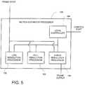
- Fig. 5is a schematic illustration in detail of motion estimation processor 108, constructed and operative in accordance with a further preferred embodiment of the invention.
- Fig. 6is a schematic illustration of a video frame, generally referenced 170, including three resolution representation of a portion of this frame, generally referenced A, B and C.
- Motion estimation processor 108includes a low resolution processor 150, a full resolution processor 152, a hyper resolution processor 154 and a micro-controller 158.
- the frame input of the motion estimation processor 108is connected to the inputs of the low resolution processor 150, the full resolution processor 152, the hyper resolution processor.
- the frame output of motion estimation processor 108is connected to the hyper resolution processor 154.
- the micro-controller 158is connected to the low resolution processor 150, the full resolution processor 152 and the hyper resolution processor and the control port of the motion estimation processor 108, which is connected to global controller 110 ( Fig. 3 ).
- frame 170is a [6x6] matrix which includes a digital representation of a video frame F i .
- the currently scanned blockis block
- Frame 170is provided to processors 150, 152 and 154 ( Fig. 5 ).
- motion estimation processor 108can operate in two modes: a programming mode and an operational mode.
- the motion estimation processorcan operate according to both modes at the same time.
- the global controller 110( Fig. 3 ) provides control parameters as well as data parameters, to micro-controller 158, via the control port.
- Micro-controller 158controls and synchronizes processors 150, 152 and 154. According to a preferred embodiment of the present invention, processors 150, 152 and 154 operate either in a parallel or in a serial manner.
- the low resolution processor 150processes i-th macro-block, while the full resolution processor 152 processes I-1-th macro-block, whereas the hyper resolution processor 154 processes I-2-th macro-block, all at the same time.
- the low resolution processor 150processes i-th macro-block, while both full resolution processor 152 and the hyper resolution processor 154 process I+1-th macro-block in a serial manner.
- Low resolution processor 150operates as follows.
- the global controller 110loads the current picture macro-block and the reference pictures data blocks into the low resolution processor 150.
- the low resolution processor 150performs a resolution reduction, resulting in decreasing the amount of image data.
- the low resolution processor 150can perform the resolution reduction by different methods, like decimation, low pass filtering, non-linear filtering, and the like.
- Block Ais a [2x2] matrix, wherein pixel A:(1,1) is a combined representation of pixels B:(1,1), B:(1,2), B:(2,1) and B:(2,2), pixel A:(2,1) is a combined representation of pixels B:(3,1), B:(3,2), B:(4,1) and B:(4,2), pixel A:(1,2) is a combined representation of pixels B:(1,3), B:(1,4), B:(2,3) and B:(2,4) and pixel A:(2,2) is a combined representation of pixels B:(3,3), B:(3,4), B:(4,3) and B:(4,4).
- Such pixel combinationcan be performed in many ways such as calculating the average value of the combined pixels, selecting the dominant one, and the like.
- the resolution reduction of the present exampleis at a ratio of 1:4. It will be noted that low resolution processor 150 can perform a resolution reduction at any ratio desired.
- low resolution processorAfter low resolution processor completes the resolution reduction, then, it performs a search procedure.
- the low resolution processor 150can performs different types of search, like full exhaustive search, telescopic search, and the like, thereby producing low resolution motion analysis.
- the global controller 110Fig. 3
- the global controller 110reads the low resolution motion analysis data from the low resolution processor 150, via the local controller 158.
- Full resolution processor 152operates as follows: The global controller 110 loads the current picture block (referenced B in Fig. 6 ) and the reference pictures data block into the full resolution processor 152, according to the low resolution motion analysis. Then, the full resolution processor 152 performs a search procedure.
- the full resolution processor 152can perform different types of search, like full exhaustive search, telescopic search, and the like, thereby producing full resolution motion analysis. After the search is completed, the global controller 110 reads the full resolution motion analysis data from the full resolution processor 152, via the local controller 158.
- Full resolution processor 152 and hyper resolution processor 154can have a shared storage area. This aspect of the invention reduces the memory requirements of the encoding system.
- Hyper resolution processor 154operates as follows: The global controller 110 loads the current picture macro-block and the reference pictures data blocks into the hyper resolution processor 154. The hyper resolution processor 154 multiplies the resolution of the image data, enabling a motion prediction with a resolution higher than a single pixel step.
- Hyper resolution processor 154can perform the resolution multiplication by different methods, like zero order interpolation, first order interpolation, and the like.
- hyper resolution processor 154( Fig. 5 ) generates a hyper resolution block C from block B.
- Block Cis a [9x9] matrix, wherein pixels C:(1,1), C:(3,1), C:(5,1), C:(7,1), C:(1,3), C:(3,3), C:(5,3), C:(7,3), C:(1,5), C:(3,5), C:(5,5), C:(7,5), C:(1,7), C:(3,7), C:(5,7) and C:(7,7) are equal to pixels B:(1,1), B:(2,1), B:(3,1), B:(4,1), B:(1,2), B:(2,2), B:(3,2), B:(4,2), B:(1,3), B:(2,3), B:(3,3), B:(4,3), B:(1,4), B:(2,4), B:(3,4) and B:(4,4), respectively.
- Each other pixel in block Ccan be an interpolation of selected B: pixels adjacent to its respective place therein.
- pixel C:(2,2)is an interpolation of pixels B:(1,1), B:(1,2), B:(2,1) and B:(2,2).
- Pixel C:(2,1)is an interpolation of pixels B:(1,1), and B:(2,1).
- Pixel C:(1,0)is an interpolation of pixels B:(1,0), and B:(1,1).
- the resolution enhancement of the present exampleis at a ratio of 4:1. It will be noted that hyper resolution processor 154 can perform a resolution enhancement at any ratio desired.
- the hyper resolution processor 154After the hyper resolution processor 154 completes the resolution multiplication, it performs a search procedure.
- the hyper resolution processor 154can perform different types of search, like full exhaustive search, telescopic search, and the like, thereby producing hyper resolution motion analysis.
- the global controller 110reads the hyper resolution motion analysis data, from the hyper resolution processor 154, via the local controller 158.
- a motion estimation processorcan include as many resolution processors as desired, wherein some resolution processors are low resolution processors, at a variety of low resolutions and other resolution processors are hyper resolution processors, at a variety of hyper resolutions.
- Fig. 7is a schematic illustration in detail of digital signal processor 104, of Fig. 3 , constructed and operative in accordance with another preferred embodiment of the invention.
- Digital signal processor 104includes a master controller 250, a random access unit (RAM) 270 and N processing units 252, 254, 256, 258, 260 and 262. Each processing unit 252, 254, 256, 258, 260 and 262 is connected to the master controller 250 and to the RAM 270.
- RAMrandom access unit
- the processing units 252, 254, 256, 258, 260 and 262are further connected to motion estimation processor 108 and to the global controller 110 ( Fig. 3 ), for retrieving macro block data therefrom.
- Digital signal processor 104can operate in two modes: a programming mode and an operational mode. Digital signal processor 104 can operate according to both modes at the same time.
- the global controller 110( Fig. 3 ) transfers data and control parameters to/from master controller 250.
- the master controller 250can independently program each processing unit 252, 254, 256, 258, 260 and 262.
- the master controller 250 and all processing units 252, 254, 256, 258, 260 and 262,operate in parallel.
- the motion estimation processor 108( Fig. 3 ) transfers the current macro-block and the reference macro-blocks data to the processing units 252, 254, 256, 258, 260 and 262 of the digital signal processor 104.
- the motion estimation processor 108( Fig. 3 ) provides luminance macro-blocks and the global controller 110 provides chrominance macro-blocks retrieved from memory unit 122.
- the global controller 110transfers the appropriate data (like motion vectors, macro-block type, perdition type, and the like) to the master controller 250.
- the master controller 250performs special processing procedures such as like rate control, DCT type selection, macro-block type selection and the like.
- the master controller 250distributes control instructions to the processing units 252, 254, 256, 258, 260 and 262, and receives processed data from each of these processing units.
- Processing units 252, 254, 256, 258, 260 and 262perform processing procedures on large data blocks, such as discrete cosine transform (DCT), inverse discrete cosine transform (IDCT), quantization, inverse quantization, frame type decisions, and the like.
- DCTdiscrete cosine transform
- IDCTinverse discrete cosine transform
- quantizationinverse quantization
- inverse quantizationinverse quantization
- Each of these processing unitsprocesses different data blocks. Each processing unit can access the data blocks associated with other processing units, in RAM 270. All processing unit can execute different operations in parallel.
- the processing unitstransfer the processed coefficient data to the bit-stream processor 102 ( Fig. 3 ).
- the master controller 250 of the digital signal processor 104transfers the appropriate data (like macro-block type, DCT type, quantizer scale, etc.) to the global controller 110 ( Fig. 3 ).
- the present inventionovercomes the disadvantages of the prior art by configuring the master controller 250 so as to perform individual processing tasks on some data items while the processing units 252, 254, 256, 258, 260 and 262, simultaneously perform massive processing tasks on large data blocks.
- the master controller 250temporarily assigns a storage area in RAM 270, to each of the processing unit 252, 254, 256, 258, 260 and 262.
- each processing unit 252, 254, 256, 258, 260 and 262can access the data which is associated with the other processing units. It will be appreciated by those skilled in the art that such a structure greatly enhances the efficiency of processing and data transfer operations in DSP 104. Such parallel access structure of the processing units also allows very fast and efficient data transfer to and from the digital signal processor 104.
- FIG. 8is a schematic illustration in detail of a digital signal processor, generally referenced 144, constructed and operative in accordance with a further preferred embodiment of the invention.
- Digital signal processor 144is generally similar to digital signal processor 104, with a slightly different memory structure.
- Digital signal processor 144includes a master controller 288, N processing units 271, 274, 276, 280, 282 and 286 and N/2 random access units (RAM) 272, 278 and 284.
- master controller 288N processing units 271, 274, 276, 280, 282 and 286 and N/2 random access units (RAM) 272, 278 and 284.
- RAMrandom access units
- Each RAM unitis connected to two processing unit. Processing units 271 and 274 are connected to RAM unit 272. Processing units 276 and 280 are connected to RAM unit 278. Processing units 282 and 286 are connected to RAM unit 284.
- Each processing unitis able to access any address in the RAM unit connected thereto.
- FIG. 9is a schematic illustration in detail of video input processor 106, of Fig. 3 , constructed and operative in accordance with a further preferred embodiment of the invention.
- Video input processor 106includes a video capture unit 230, a video preprocessor 232 and a temporary video storage 236.
- the inputs of the video capture unit 230, the video preprocessor 232 and the temporary video storage 236are connected to the video input processor 106 ( Fig. 3 ).
- the input of the video capture unit 230is connected to video input processor 106.
- the video capture unit 230is connected to the video preprocessor 232.
- the video preprocessor 232is connected to the temporary video storage 236.
- the output of the temporary video storage 236is connected to the global controller 110.
- Video input processor 106operates in two modes: programming and operational. Video input processor 106 is operative to run according to both modes at the same time. In the programming mode, the global controller 110 ( Fig. 3 ) loads data and control parameters to the video capture unit 230, to the video preprocessor 232 and to the temporary video storage 236.
- the video capture unit 230acquires the input video signal.
- the video capture unit 230is self synchronized with the input video signal, according to its format (NTSC, PAL, SECAM, and the like), programmable resolution (D1, SIF, QSIF, and the like), and the like.
- the video capture unit 230also provides video synchronization signals (like a new frame start, a new field start, etc.) to the global controller 110.
- the video preprocessor 232performs a series of video processing procedures to enhance the captured video signal.
- the video processing procedurescan include a color format conversion, size reduction, noise reduction, edge sharpening, image quality improvement, and the like.
- the temporary video storage 236accumulates the processed video signal and provides a "data ready" signal to the global controller 110 ( Fig. 3 ).
- the global controller 110reads the accumulated image data from the temporary video storage 236.
- the global controller 110also provides control signals to the video input processor 106.
- the usage of the temporary video storage 236allows to efficiently adjust the data rates of an external video signal and the internal data transfer.
- the video input processor 106can accumulate the processed video signal in a real time variable rate whereas the global controller 110 can transfer the accumulated data to the memory unit 122 in a burst. This greatly reduces the memory bandwidth requirements, and makes the usage of a memory unit 122 more efficient.
- Fig. 10is a schematic illustration in detail of bit-stream processor 102, of Fig. 3 , constructed and operative in accordance with a further preferred embodiment of the invention.
- Bit-stream processor 102includes a local processing unit 356, an entropy encoder 358, a temporary coefficient storage 360, a bit-stream formatter 352, an output buffer 354 and a micro-controller 350.
- the input of the bit-stream processor 102is connected to the input of the temporary coefficient storage 360 and of the local processing unit 356.
- the temporary coefficient storage 360is connected to the entropy encoder 358.
- the entropy encoder 358is further connected to the local processing unit 356 and to the bit-stream formatter 352.
- the local processing unit 356is further connected to the output of the bit-stream processor 102.
- the bit-stream formatter 352is connected to the output buffer 354.
- the output of the output buffer 354is connected to the output of the bit-stream processor 102.
- the input of the micro-controller 158is connected to the input of the bit-stream processor 102.
- the micro-controller 158 of the bit-stream processor 102is connected to the processing unit, the entropy encoder 358, temporary coefficient storage 360, bit-stream formatter 352 and output buffer 354.
- the bit-stream processor 102can operate in two modes: programming and operational. Bit-stream processor 102 is operative to run according to both modes at the same time.
- the global controller 110In the programming mode, the global controller 110 ( Fig. 3 ) loads the data and control parameters to micro-controller 350 and to local processing unit 356.
- the digital signal processor 104( Fig. 3 ) loads the processed coefficients to the temporary coefficient storage 360.
- the entropy encoder 358loads the data from the local processing unit 356 registers and the temporary coefficient storage 360.
- the entropy encoder 358performs a series of encoding procedures, like zigzag/alternate scan, run-length encoding, variable length encoding of data, and the like, thereby producing encoded data.
- the local processing unit 356performs arithmetic and logical operations required to support the entropy encoding.
- the local processing unit 356also provides a temporary storage for the data loaded from the global controller 110 ( Fig. 3 ) in the programming mode.
- the bit-stream formatter 352reads the encoded data from the entropy encoder 358 and formats it into a standard bit-stream.
- the output buffer 354provides a temporary storage to the bit-stream data.
- the micro-controller 350provides the control and synchronization signals to the local processing unit 356, the entropy encoder 358, the temporary coefficient storage 360, the bit-stream formatter 352 and the output buffer 354.
- the global controller 110can put the bit-stream processor 102 into programming or operational mode by loading an appropriate control signal to the micro-controller 158 of the bit-stream processor 102.
- Entropy encoding and computational operations in the bit-stream processor 102are performed in parallel, by operating entropy encoder 358 and processing unit 356, simultaneously. This allows a very efficient utilization of the bit-stream processor 102 resources.
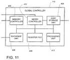
- Fig. 11is a schematic illustration in detail of global controller 110, of Fig. 3 , constructed and operative in accordance with another preferred embodiment of the invention.
- Global controller 110includes a memory controller 400, an exchange unit 406, a register file 408, a processing unit 410, a host storage 404 and a micro-controller 402.
- the input of the micro-controller 402is connected to the input of the global controller 110.
- the micro-controller 402is connected to the memory controller 400, exchange unit 406, register file 408, processing unit, host storage 404 and to output of global controller 110.
- the external storage interface of the global controller 110is connected to the memory controller 400.
- the input/output of the memory controller 400is connected to the input/output of the global controller 110 respectively.
- the exchange unit 406is connected to the register file 408.
- the register file 408is connected to the processing unit 410 and to the host storage 404 of the global controller 110.
- the host storage 404is connected to the host interface 120 ( Fig. 3 ).
- the global controller 110schedules, synchronizes and controls motion estimation processor 108, digital signal processor 104, bit-stream processor 102 and video input processor 106.
- the global controller 110controls the internal data transfer of device 100 and the external data transfer from device 100 to external devices such as memory unit 122, an external host, and the like.
- the global controller 110can also initializes and performs a variety of testing procedures on motion estimation processor 108, digital signal processor 104, bit-stream processor 102 and video input processor 106 and also memory unit 122.
- the global controller 110is a massively parallel processor, capable of simultaneous execution of computational operations, internal data transfer and external data transfer.
- the global controller 110operates in two modes: programming and operational. Global controller 110 is operative to run according to both modes at the same time.
- an external hostloads the data and control parameters to the host storage 404.
- the external hostinstruct the global controller 110 to perform according to the operational mode by loading a predetermined control signal into the host storage 404.
- the micro-controller 402is synchronized to an external video source by the video synchronization signal which comes from the video input processor 106 ( Fig. 3 ).
- the micro-controller 402provides control and synchronization signals to the motion estimation processor 108, the digital signal processor 104, the bit-stream processor 102 and the video input processor 106.
- the micro-controller 402can also instruct each of these units to perform in accordance with a programming mode or an operational mode.
- the global controller 110loads a new frame from the video input processor 106 to the memory controller 400.
- the memory controller 400transfers this data to the external storage.
- the memory controller 400also reads the current and reference frames macro-blocks from the external storage and transfers them to the motion estimation processor 108 ( Fig. 3 ).
- the memory controller 400provides the control signals, addresses and the like to memory unit 122 ( Fig. 3 ).
- the exchange unit 406 of the global controller 110reads and writes different data items to and from the motion estimation processor 108, the digital signal processor 104, the bit-stream processor 102 and the video input processor 106.
- the exchange unit 406transfers the data to and from the register file 408.
- register file 408maintains a memory structure such as a stack, which contains the sets of parameters associated with each macro-block.
- This memory structurecan be divided into multiple stacks of variable depth.
- the processing unit 410can read the data from the register file 408, perform various arithmetic and logical operations, and store the processed data back into register file 408.
- the register file 408can access the host storage 404 to retrieve the data which an external host loaded into the host storage 404 during the programming mode.
- the register file 408can also transfer the data to the host storage 404, such that an external host can access the data during both programming and operational modes.
- FIG. 12is a schematic illustration of encoding device 100, incorporated in a video camera, generally referenced 500, constructed and operative in accordance with another preferred embodiment of the invention.
- Camera 500includes an optical assembly 502, a charge coupled device (CCD) 510, a host interface 504, a random access memory 506, a communication interface 520, two storage units 508 and 516 and encoding device 100.
- CCDcharge coupled device
- Device 100is connected charge coupled device 510, host interface 504, a communication interface 520, random access memory 506 and storage units 508 and 516.
- Host interface 504includes a display 514 and a keyboard 512 and can be used to display the status of encoding device 100 as well as to receive instructions from a user.
- Storage unit 508is a tape based storage device.
- Storage unit 516is a disk based storage device, such as a magnetic hard drive, an optical storage device, a magneto-optical storage device and the like. It will be noted that other types of storage devices can also be used for this purpose, like semiconductor based memory units such as flash memory, RAM and the like.
- CCD 510converts light, arriving from the optical assembly 502, representing an image, into an electrical signal.
- CCD 510is preferably a digital light sensitive device which can be replaced by an analog light sensitive device, followed by an analog to digital converter, for converting an analog video signal into a digital video signal.
- CCD 510provides the digital video signal to video input processor 106, of encoding device 100.
- the encoding device 100encodes the digital video signal, produces an encoded video signal and provides it at the output of bit-stream processor 102.
- the encoding device 100uses a random access memory 506 as a temporary storage area for video data as well as analysis data, produced by its inner components.
- Encoding device 100provides the encoded video signal to storage devices 508 and 516, and to communication interface 520.
- any of the storage units 508 and 5016 as well as the communication interface 520can provide digital video signal as input for device 100.
- storage device 516is also connected to device 100 via the video input processor 106.
- the present inventionprovides an encoding device which can easiely be adapted to ISO/IEC 11172 (MPEG-1) as well as other encoding standards which are similar to MPEG such as ISO/IEC H.320, H.261 and H.263, as well as different motion JPEG methods.
Landscapes
- Engineering & Computer Science (AREA)
- Multimedia (AREA)
- Signal Processing (AREA)
- Computing Systems (AREA)
- Theoretical Computer Science (AREA)
- Compression Or Coding Systems Of Tv Signals (AREA)
- Compression, Expansion, Code Conversion, And Decoders (AREA)
Description
- The present invention relates to video encoding devices in general and to single chip video encoding devices, in particular.
- Methods for encoding an audio-visual signal are known in the art. According to these methods, a video signal is digitized, analyzed and encoded in a compressed manner. These methods are implemented in computer systems, either in software, hardware or a combined software-hardware form.
- Most hardware encoding systems consist of a set of semiconductor circuits, which are arranged on a large circuit board. State of the art encoding systems include a single semiconductor circuit, which is based on a high power processor.
- Reference is now made to
Fig. 1 , which is a schematic illustration of a video encoding circuit, referenced 10, which is known in the art. Circuit 10 includes amotion estimation processor 12, amotion estimation memory 14 connected to themotion estimation processor 12, aRISC processor 16 connected to themotion estimation processor 12 and animage buffer 18, connected toRISC processor 16.RISC processor 16 transfers a portion of video signal fromimage buffer 18 tomemory unit 14.Motion estimation processor 12 analyzes the motion of the video signal.Motion estimation processor 12 utilizesmemory unit 14 as a storage area for the video signal portion which is currently processed by it. When themotion estimation processor 12 completed analyzing the motion of a video signal portion, it transfers the results of the motion estimation analysis to theRISC processor 16.- The
RISC processor 16 performs all other processing and encoding tasks which the video signal has to undergo, such as discrete COSINE transform (DCT), quantization, entropy encoding, bit-stream production and the like. TheRISC processor 16 utilizes theimage buffer 18 as a storage area for the video signal portion which is currently processed by it, and as a temporary storage for its computational purposes. - It will be appreciated by those skilled in the art that such encoding systems have several disadvantages. For example, one disadvantage of
circuit 10 is that each of theprocessing units memory unit 14 andimage buffer 18.RISC processor 16 has to accessimage buffer 18 for the same data, each time this data is required. Such Retrieval of large data blocks, many times, greatly increases data traffic volume over the encoding system data transmission lines. - Another disadvantage is that
circuit 10 is able to execute all processing and encoding tasks in a serial manner, thereby capable of processing only a single macro-block at a time, requiring high operational processor frequencies.Circuit 10 receives a macro-block, processes it and produces an encoded bit-stream. Internally, the RISCprocessor 16 operates in the same manner. - Hence, as long as the
RISC processor 10 hasn't completed transmitting the encoded bit-stream of a selected macro-block, it cannot receive the next macro-block. - It will be appreciated by those skilled in the art that the operational frequency of
circuit 10 has a direct affect over the heat produced by it, thereby requiring large cooling elements as well as massive cooling devices such as fans and the like. - It will be appreciated by those skilled in the art that such circuit structure requires that input-output (I\O) operations have to be performed extremely fast, thereby greatly increasing the storage memory bandwidth requirements.
- Another disadvantage of such systems is that all processing and encoding procedures (excluding motion estimation) are executed by the same RISC processor. In this case, the same circuit performs various types of computations, which makes the utilization of the processor's hardware resources very inefficient.
- Methods for estimating motion in a video signal are known in the art. According to these methods a frame is compared with previous frames. The difference between the frames is used to estimate a level of motion. These methods analyze a frame and map it, thereby indicating areas in frame which have no motion over previous frames and areas in the frame which are assigned with a motion level.
- According to one such like method each pixel in the search area is analyzed. This method requires a vast number of estimation operations and is thereby extremely resource consuming. This method is also called a full exhaustive search.
- According to another method, known in the art, the search area is scanned in a center weighted manner, which can be logarithmic, and the like, whereby the center of the search area is scanned thoroughly at full resolution and the rest of the search area is scanned at lower resolution. Areas which detected as having some motion, in the low resolution search, are scanned again in full resolution. This reduces the overall number of estimation operations.
- Reference is now made to
Fig. 2 , which is a schematic illustration of a DSP processor, referenced 50, which is known in the art. - DSP
processor 50 is of a single instruction multiple data (SIMD) type machine. It includes a plurality of identical processing units (P.U.) 52, 56, 60, 64, 68 and 72, and a random access memory (RAM) 61.RAM 61 is divided intosegments - Each memory segment is exclusively assigned and connected to a processing unit, whereas
RAM segment units - This structure has several disadvantages. One disadvantage of such machine is that the same operation is performed by all of the processing units at same time.
- Another disadvantage of the SIMD machine is that the data is not shared among the processing units. For example,
processing unit 56 can access data contained inRAM segment 66 viaprocessing unit 64 only. It cannot do so directly. It will be appreciated by those skilled in the art that such a configuration is inefficient. - A further disadvantage is that individual operations that vary for different data items can not be efficiently performed by an SIMD machine. The programming of such operations into the processing units, is very difficult. Such individual operations can be only performed in serial manner, while masking all irrelevant data, resulting in shutting off most of the processing units. The utilization of the hardware resources in an SIMD machine during such programming operations is very low, and performance of the machine are dramatically decreased.
- Another disadvantage relates to the interconnection structure between the processing units. It will be appreciated that, a processing unit within an SIMD machine is connected to a limited number of neighboring processing units. Hence communication between such a processing unit and a processing unit not connected thereto, is often a complex operation.
- Bit-stream processing and generation, in a conventional encoding circuit, is performed by a general purpose processor. Bit-stream generation requires some specific operations, which can not be performed efficiently by a general purpose processor. In order to perform such special operation, a general purpose processor uses a small portion of its processing resources, while shutting off rest of them. Therefore, the disadvantage is that the resources of such processor are not utilized efficiently.
- Patent publication
US 5 610 658 discloses an amount-of-movement detection device which is capable of detecting the amount of movement with a high degree of accuracy when the amount of movement of an image is detected by a hierarchical block matching method. Image data of plural hierarchies having different resolutions from each other is formed from an input image. Image data of a higher hierarchy has a lower resolution and is formed from image data input at two separate points in time. - It is an object of the present invention to provide a novel device for encoding an audio-visual signal, which overcomes the disadvantages of the prior art.
- It is another object of the present invention to provide a novel motion estimation processor.
- It is a further object of the present invention to provide a novel DSP for processing framed information.
- In accordance with the present invention there is thus provided a video encoding system including a video source providing multiple frame video signal, a memory unit, a compressed data interface, a host interface and a video encoding device, connected to the video source, the memory unit and the host interface. The video encoding device includes a video input processor, for receiving the video signal, a global controller, for controlling the global operation of the video encoding device, connected to the video input processor, a motion estimation processor, connected to the global controller, a digital signal processor, connected to the global controller and the motion estimation processor, and a bit-stream processor connected to the digital signal processor and the global controller and the compressed data interface.
- The global controller stores encoding commands received from the host interface thereby programming the video input processor, the motion estimation processor, the digital signal processor and the bit-stream processor.
- The video input processor receives and stores the video signal in the memory unit.
- The motion estimation processor retrieves the video signal from the memory unit, generates motion analysis of the video signal, stores the motion analysis in the memory unit and provides the motion analysis to the digital signal processor.
- The digital signal processor processes the video signal according to the motion analysis, thereby producing an encoding commands sequence and encoded data.
- The bit-stream processor produces an encoded video signal according to the encoding command sequence and the encoded data.
- According to another aspect of the invention at least one of the video input processor, the motion estimation processor, the digital signal processor and the bit-stream processor is directly connected to the memory unit.
- According to another aspect of the invention at least one of the video input processor, the motion estimation processor, the digital signal processor and the bit-stream processor is connected to the memory unit via the global controller.
- The motion estimation processor, the digital signal processor and the bit-stream processor can operate in parallel, whereas the motion estimation processor operates on a macro-block i, the digital signal processor operates on a macro-block j and the bit-stream processor operates on a macro-block k, wherein i>j>k.
- Furthermore, in accordance with a preferred embodiment of the invention the entire video encoding device in constructed on a monolithic semiconductor.
- According to another aspect of the invention the motion estimation processor includes a controller and a plurality of resolution processors, connected to the controller. The plurality of resolution processors analyze the development of the video signal in time, thereby producing motion analysis. The controller controls the plurality of resolution processors.
- The plurality of resolution processors include at least one low resolution processor, for producing low resolution motion analysis, at least one full resolution processor, for producing full resolution motion analysis and at least one hyper resolution processor, for producing hyper resolution motion analysis.
- At least one of the least one low resolution processor reduces the resolution of a selected frame before producing the low motion analysis and at least one of the least one hyper resolution processors, enhances the resolution of a selected frame before producing the hyper resolution motion analysis.
- The plurality of resolution processors include at least one full resolution processor, for producing full resolution motion analysis. The one full resolution processor processes the selected frame according to the low resolution motion analysis.
- The plurality of resolution processors include at least one hyper resolution processor, for producing hyper resolution motion analysis, wherein at least one of the hyper resolution processors, processes a selected frame according to the full resolution motion analysis.
- The digital signal processor includes a DSP controller, a plurality of processing units, for processing the multiple frame video digital signal, connected to the DSP controller, and at least one storage unit. Each of the processing units is connected to at least one of the storage units. The DSP controller controls the plurality of processing units.
- Each of the processing units is operative to access any storage address of any of the storage units, connected thereto. Each of the processing units is capable of operating according to a different program command. Each of the processing units operates on a different portion of data.
- In accordance with a further aspect of the present invention, there is provided a video camera including an optical assembly, a light sensitive device, and the video encoding device, connected to the light sensitive device.
- The present invention will be understood and appreciated more fully from the following detailed description taken in conjunction with the drawings in which:
Fig. 1 is a schematic illustration of an encoding circuit, known in the art;Fig. 2 is a schematic illustration of an DSP unit, which is known in the art;Fig. 3 is a schematic illustration of a video encoding device, constructed and operative in accordance with a preferred embodiment of the invention;Fig. 4 is a schematic illustration of a video encoding device, constructed and operative in accordance with another preferred embodiment of the invention;Fig. 5 is a schematic illustration in detail of the motion estimation processor, of the video encoding device of the device ofFig. 3 , constructed and operative in accordance with a further preferred embodiment of the invention;Fig. 6 is a schematic illustration of a video frame, including three resolution representation of a portion of this frame;Fig. 7 is a schematic illustration in detail of the digital signal processor, of the video encoding device ofFig. 3 , constructed and operative in accordance with another preferred embodiment of the invention;Fig. 8 is a schematic illustration in detail of a digital signal processor, constructed and operative in accordance with a further preferred embodiment of the invention;Fig. 9 is a schematic illustration in detail of the video input processor, of the encoding device ofFig. 3 , constructed and operative in accordance with a further preferred embodiment of the invention;Fig. 10 is a schematic illustration in detail of the bit-stream processor, of the encoding device ofFig. 3 , constructed and operative in accordance with another preferred embodiment of the invention;Fig. 11 is a schematic illustration in detail of the global controller of the encoding device ofFig. 3 , constructed and operative in accordance with another preferred embodiment of the invention; andFig. 12 is a schematic illustration in detail of the encoding device ofFig. 3 , incorporated in a video camera, constructed and operative in accordance with a further preferred embodiment of the invention.- The present invention overcomes the disadvantages of the prior art by providing a novel approach to video compression processing and a novel structure for a device, according to this approach.
- The device according to the invention is a massively parallel digital video processor designed, for the purpose of real-time video encoding, like MPEG. This device can be incorporated in a single chip, and installed in digital camcorders, recordable digital video disk (DVD), PC and workstation multimedia, educational and training systems, video conferencing, broadcast equipment, security, content creation/authoring/video editing equipment, and the like.
- Reference is now made to
Fig. 3 , which is a schematic illustration of a video encoding device, generally referenced 100, constructed and operative in accordance with a preferred embodiment of the invention. Device 100 includes avideo input processor 106, amotion estimation processor 108, adigital signal processor 104, a bit-stream processor 102 and aglobal controller 110.- The
video input processor 106 is connected to theglobal controller 110. Themotion estimation processor 108 is connected to theglobal controller 110 and to thedigital signal processor 104. Thedigital signal processor 104 is connected to theglobal controller 110 and to the bit-stream processor 102, which is also connected to theglobal controller 110. - The bit-
stream processor 102 is further connected to acompressed data interface 128. Theglobal controller 110 is further connected to ahost interface 120 and to amemory unit 122. The input of thevideo input processor 106 is further connected to a digital video source (not shown) via adigital video interface 124. Such a host is typically a user interface which is operative to receive commands, operational parameters, and the like, from a user or a supervising system and also to provide to the user information received fromdevice 100. Device 100 operates in two modes: a programming mode and an operational mode.Device 100 is operative to run according to both modes at the same time. In the programming mode, an external host transfers the data and control parameters to theglobal controller 110, via thehost interface 120.- The
global controller 110 can transfer the data and control signals to thevideo input processor 106,motion estimation processor 108,digital signal processor 104 and bit-stream processor 102. - In the operational mode, the
video input processor 106 captures motion video signal from an external video source via the digitizedvideo interface 124.Video input processor 106 also performs preprocessing of the video signal, such as spatial filtering, noise reduction, image quality improvement, image size adjustment, and the like, color format conversion, and the like, thereby producing preprocessed video data. Video input processor 106 accumulates the preprocessed video data into data blocks and transfers them to theglobal controller 110.Global controller 110 stores the data blocks inmemory unit 122. In the present example, the device operates under MPEG-2 video compression standard. Hence, a data block represents an MPEG-2 macro-block, which is a sixteen by sixteen [16x16] matrix of luminance pixels and two, four or eight, eight by eight [8×8] matrices of chrominance pixels, as defined by the MPEG-2 standard. A reference frame represents a picture which is compared versus current picture during the motion estimation.- The
global controller 110 retrieves a current picture macro-block and reference picture macro-blocks from thememory unit 122 and loads them to themotion estimation processor 108.Motion estimation processor 108 compares the current picture macro-block with the respective reference frame macro-blocks, thereby producing an estimation of the motion of the current picture macro-block. - The
motion estimation processor 108 uses this estimation to remove temporal redundancy of the video signal, as will be described in detail hereinbelow. Themotion estimation processor 108 transfers the resulting motion estimation data to theglobal controller 110.Motion estimation processor 108 also transfers the current picture macro-block and the corresponding reference frames macro-blocks to thedigital signal processor 104. - Digital signal processor 104 (DSP) executes procedures which are intended to remove the spatial redundancy of the video signal, thereby producing a sequence of compression commands, as will be described in detail hereinbelow. This sequence of compression commands includes instruction as to which frame of the original video signal is to be compressed into an I-frame, a B-frame or a P-frame, and according to which reference frames.
- Then, the
digital signal processor 104 transfers the sequence of compressed data to the bit-stream processor 102 and to theglobal controller 110. The bit-stream processor 102 performs a series of encoding procedures, such as entropy encoding, and the like, as will be described in detail hereinbelow. - The bit-
stream processor 102 compresses data into an MPEG-2 standard format data, in accordance with the sequence of compression commands. - Then, the bit-
stream processor 102 transfers the MPEG-2 standard format data to thecompressed data interface 128. It will be noted thatcompressed data interface 128 can be connected to any data receptacle element such as a storage unit or a communication transmission line. Global controller 110 controls and schedules thevideo input processor 106, themotion estimation processor 108, thedigital signal processor 104 and the bit-stream processor 102.Global controller 110 also governs the data transfer among themotion estimation processor 108,digital signal processor 104 and the bit-stream processor 102.- The
global controller 110 also connects between the external host andvideo input processor 106,motion estimation processor 108,digital signal processor 104 and bit-stream processor 102. In the operational mode, an external host can access the register file 408 (Fig. 10 ) ofglobal controller 110 for read and/or write operations. - According to one aspect of the invention, in operational mode, macro-blocks are fed into
device 100, in a horizontal or vertical raster scan manner, from the top left macro-block through to the right bottom macro-block, of a specified frame.Device 100 processes a number of successive macro-blocks, at the same time. For example, while the bit-stream processor 102 processes the i-th macro-block,digital signal processor 104 processes the i+1-th macro-block andmotion estimation processor 108 processes the i+2-th through i+4-th macro-blocks. - According to another example, while the bit-
stream processor 102 processes the i-th macro-block,digital signal processor 104 processes the k-th macro-block andmotion estimation processor 108 processes the j-th through j+m-th macro-blocks, wherein i<k<j and m≥1. Device 100 overcomes a disadvantage of the prior art by usingmemory unit 122 as a shared storage area which is accessible to all of its internal units, viaglobal controller 110. In the present example, all access tostorage unit 122 is provided viaglobal controller 110.- Reference is now made to
Fig. 4 , which is a schematic illustration of a video encoding device, generally referenced 200, constructed and operative in accordance with another preferred embodiment of the invention. Device 200 is generally similar todevice 100 and includes avideo input processor 206, amotion estimation processor 208, adigital signal processor 204, a bit-stream processor 202 and aglobal controller 210.Device 200 is also connected to acompressed data interface 228, amemory unit 222, a digital video source (not shown) via adigital video interface 224 and ahost interface 220. Indevice 200, all of the internal components are connected directly tomemory unit 222.- Accordingly,
video input processor 206,motion estimation processor 208,digital signal processor 204, bit-stream processor 202 andglobal controller 210 can, each, access any storage address withinmemory unit 222, directly, thereby performing any I\O operation. - It will be noted that a shared memory structure according to the invention can include a combination of the examples disclosed in
Figs. 3 and4 , whereby some components are directly connected to memory unit and the rest are connected to the memory unit via a mediating element, such asglobal controller 110. - Referring back to
Fig. 3 , it is noted that according to another aspect of the invention,memory unit 110 can partitioned into many sub-areas, whereby each of the internal units ofdevice 100, is granted an access level which is selected from a list of access levels such as read-write, read only, write only, no access and the like. It will be appreciated by those skilled that such a structure provides tremendous flexibility, whereby the amount of memory assigned to a selected internal unit can be increased or decreased dynamically, in real-time. - According to another aspect of the present invention,
device 100 performs different processing and encoding procedures in parallel, by processing a number of successive macro-blocks simultaneously. Hence, a selected macro-block is permitted to be present in thedevice 100 for an extended period of time, with comparison to device 10 (Fig. 1 ), thereby greatly reducing the operational frequency ofdevice 100, by factor of at least five. - Reference is now made to
Figs. 5 and6 .Fig. 5 is a schematic illustration in detail ofmotion estimation processor 108, constructed and operative in accordance with a further preferred embodiment of the invention.Fig. 6 is a schematic illustration of a video frame, generally referenced 170, including three resolution representation of a portion of this frame, generally referenced A, B and C. Motion estimation processor 108 includes alow resolution processor 150, afull resolution processor 152, ahyper resolution processor 154 and amicro-controller 158. The frame input of themotion estimation processor 108 is connected to the inputs of thelow resolution processor 150, thefull resolution processor 152, the hyper resolution processor.- The frame output of
motion estimation processor 108 is connected to thehyper resolution processor 154. Themicro-controller 158 is connected to thelow resolution processor 150, thefull resolution processor 152 and the hyper resolution processor and the control port of themotion estimation processor 108, which is connected to global controller 110 (Fig. 3 ). - Referring now to
Fig. 6 ,frame 170 is a [6x6] matrix which includes a digital representation of a video frame Fi. The currently scanned block is block - B, which is a [4x4] matrix from pixel B:(1,1) to pixel B:(4,4).
Frame 170 is provided toprocessors Fig. 5 ). - Referring back to
Fig. 5 ,motion estimation processor 108 can operate in two modes: a programming mode and an operational mode. The motion estimation processor can operate according to both modes at the same time. - In the programming mode, the global controller 110 (
Fig. 3 ) provides control parameters as well as data parameters, to micro-controller 158, via the control port. Micro-controller 158 controls and synchronizesprocessors processors - In an example of parallel operation, the
low resolution processor 150 processes i-th macro-block, while thefull resolution processor 152 processes I-1-th macro-block, whereas thehyper resolution processor 154 processes I-2-th macro-block, all at the same time. - In an example of serial operation, the
low resolution processor 150 processes i-th macro-block, while bothfull resolution processor 152 and thehyper resolution processor 154 process I+1-th macro-block in a serial manner. Low resolution processor 150 operates as follows. Theglobal controller 110 loads the current picture macro-block and the reference pictures data blocks into thelow resolution processor 150. Thelow resolution processor 150 performs a resolution reduction, resulting in decreasing the amount of image data. Thelow resolution processor 150 can perform the resolution reduction by different methods, like decimation, low pass filtering, non-linear filtering, and the like.- Reference is now made to
Fig. 6 . In the present example, low resolution processor 150 (Fig. 5 ) generates a low resolution block A from block B. Block A is a [2x2] matrix, wherein pixel A:(1,1) is a combined representation of pixels B:(1,1), B:(1,2), B:(2,1) and B:(2,2), pixel A:(2,1) is a combined representation of pixels B:(3,1), B:(3,2), B:(4,1) and B:(4,2), pixel A:(1,2) is a combined representation of pixels B:(1,3), B:(1,4), B:(2,3) and B:(2,4) and pixel A:(2,2) is a combined representation of pixels B:(3,3), B:(3,4), B:(4,3) and B:(4,4). - It will be noted that such pixel combination can be performed in many ways such as calculating the average value of the combined pixels, selecting the dominant one, and the like.
- The resolution reduction of the present example is at a ratio of 1:4. It will be noted that
low resolution processor 150 can perform a resolution reduction at any ratio desired. - After low resolution processor completes the resolution reduction, then, it performs a search procedure. The
low resolution processor 150 can performs different types of search, like full exhaustive search, telescopic search, and the like, thereby producing low resolution motion analysis. After the search is completed, the global controller 110 (Fig. 3 ) reads the low resolution motion analysis data from thelow resolution processor 150, via thelocal controller 158. Full resolution processor 152 operates as follows: Theglobal controller 110 loads the current picture block (referenced B inFig. 6 ) and the reference pictures data block into thefull resolution processor 152, according to the low resolution motion analysis. Then, thefull resolution processor 152 performs a search procedure.- The
full resolution processor 152 can perform different types of search, like full exhaustive search, telescopic search, and the like, thereby producing full resolution motion analysis. After the search is completed, theglobal controller 110 reads the full resolution motion analysis data from thefull resolution processor 152, via thelocal controller 158. Full resolution processor 152 andhyper resolution processor 154 can have a shared storage area. This aspect of the invention reduces the memory requirements of the encoding system.Hyper resolution processor 154 operates as follows: Theglobal controller 110 loads the current picture macro-block and the reference pictures data blocks into thehyper resolution processor 154. Thehyper resolution processor 154 multiplies the resolution of the image data, enabling a motion prediction with a resolution higher than a single pixel step.Hyper resolution processor 154 can perform the resolution multiplication by different methods, like zero order interpolation, first order interpolation, and the like.- With reference to
Fig. 6 , in the present example, hyper resolution processor 154 (Fig. 5 ) generates a hyper resolution block C from block B. Block C is a [9x9] matrix, wherein pixels C:(1,1), C:(3,1), C:(5,1), C:(7,1), C:(1,3), C:(3,3), C:(5,3), C:(7,3), C:(1,5), C:(3,5), C:(5,5), C:(7,5), C:(1,7), C:(3,7), C:(5,7) and C:(7,7) are equal to pixels B:(1,1), B:(2,1), B:(3,1), B:(4,1), B:(1,2), B:(2,2), B:(3,2), B:(4,2), B:(1,3), B:(2,3), B:(3,3), B:(4,3), B:(1,4), B:(2,4), B:(3,4) and B:(4,4), respectively. - Each other pixel in block C: can be an interpolation of selected B: pixels adjacent to its respective place therein. For example, pixel C:(2,2) is an interpolation of pixels B:(1,1), B:(1,2), B:(2,1) and B:(2,2). Pixel C:(2,1) is an interpolation of pixels B:(1,1), and B:(2,1). Pixel C:(1,0) is an interpolation of pixels B:(1,0), and B:(1,1).
- The resolution enhancement of the present example is at a ratio of 4:1. It will be noted that
hyper resolution processor 154 can perform a resolution enhancement at any ratio desired. - After the
hyper resolution processor 154 completes the resolution multiplication, it performs a search procedure. Thehyper resolution processor 154 can perform different types of search, like full exhaustive search, telescopic search, and the like, thereby producing hyper resolution motion analysis. After the search is completed, theglobal controller 110 reads the hyper resolution motion analysis data, from thehyper resolution processor 154, via thelocal controller 158. - A motion estimation processor according to another embodiment of the invention can include as many resolution processors as desired, wherein some resolution processors are low resolution processors, at a variety of low resolutions and other resolution processors are hyper resolution processors, at a variety of hyper resolutions.
- Reference is now made to
Fig. 7 , which is a schematic illustration in detail ofdigital signal processor 104, ofFig. 3 , constructed and operative in accordance with another preferred embodiment of the invention. Digital signal processor 104 includes amaster controller 250, a random access unit (RAM) 270 andN processing units processing unit master controller 250 and to theRAM 270.- The
processing units motion estimation processor 108 and to the global controller 110 (Fig. 3 ), for retrieving macro block data therefrom. Digital signal processor 104 can operate in two modes: a programming mode and an operational mode.Digital signal processor 104 can operate according to both modes at the same time. In the programming mode, the global controller 110 (Fig. 3 ) transfers data and control parameters to/frommaster controller 250. Themaster controller 250 can independently program eachprocessing unit - In the operational mode, the
master controller 250 and all processingunits Fig. 3 ) transfers the current macro-block and the reference macro-blocks data to theprocessing units digital signal processor 104. In the present example, the motion estimation processor 108 (Fig. 3 ) provides luminance macro-blocks and theglobal controller 110 provides chrominance macro-blocks retrieved frommemory unit 122. - The
global controller 110 transfers the appropriate data (like motion vectors, macro-block type, perdition type, and the like) to themaster controller 250. Themaster controller 250 performs special processing procedures such as like rate control, DCT type selection, macro-block type selection and the like. - The
master controller 250 distributes control instructions to theprocessing units units - Each of these processing units processes different data blocks. Each processing unit can access the data blocks associated with other processing units, in
RAM 270. All processing unit can execute different operations in parallel. The processing units transfer the processed coefficient data to the bit-stream processor 102 (Fig. 3 ). Themaster controller 250 of thedigital signal processor 104 transfers the appropriate data (like macro-block type, DCT type, quantizer scale, etc.) to the global controller 110 (Fig. 3 ). - The present invention overcomes the disadvantages of the prior art by configuring the
master controller 250 so as to perform individual processing tasks on some data items while theprocessing units - According to the present example, the
master controller 250 temporarily assigns a storage area inRAM 270, to each of theprocessing unit - Hence, each
processing unit DSP 104. Such parallel access structure of the processing units also allows very fast and efficient data transfer to and from thedigital signal processor 104. - Reference is now made to
Fig. 8 , which is a schematic illustration in detail of a digital signal processor, generally referenced 144, constructed and operative in accordance with a further preferred embodiment of the invention. Digital signal processor 144 is generally similar todigital signal processor 104, with a slightly different memory structure.Digital signal processor 144 includes amaster controller 288,N processing units - Each RAM unit is connected to two processing unit. Processing
units unit 272. Processingunits unit 278. Processingunits unit 284. - Each processing unit is able to access any address in the RAM unit connected thereto.
- According to
Figs. 7 and8 it will be appreciated that the invention is not limited to any shared memory structure between processing units. - Reference is now made to
Fig. 9 , which is a schematic illustration in detail ofvideo input processor 106, ofFig. 3 , constructed and operative in accordance with a further preferred embodiment of the invention. Video input processor 106 includes avideo capture unit 230, avideo preprocessor 232 and atemporary video storage 236. The inputs of thevideo capture unit 230, thevideo preprocessor 232 and thetemporary video storage 236 are connected to the video input processor 106 (Fig. 3 ). The input of thevideo capture unit 230 is connected tovideo input processor 106. Thevideo capture unit 230 is connected to thevideo preprocessor 232. Thevideo preprocessor 232 is connected to thetemporary video storage 236. The output of thetemporary video storage 236 is connected to theglobal controller 110.Video input processor 106 operates in two modes: programming and operational.Video input processor 106 is operative to run according to both modes at the same time. In the programming mode, the global controller 110 (Fig. 3 ) loads data and control parameters to thevideo capture unit 230, to thevideo preprocessor 232 and to thetemporary video storage 236.- In the operational mode, the
video capture unit 230 acquires the input video signal. Thevideo capture unit 230 is self synchronized with the input video signal, according to its format (NTSC, PAL, SECAM, and the like), programmable resolution (D1, SIF, QSIF, and the like), and the like. - The
video capture unit 230 also provides video synchronization signals (like a new frame start, a new field start, etc.) to theglobal controller 110. - The
video preprocessor 232 performs a series of video processing procedures to enhance the captured video signal. The video processing procedures can include a color format conversion, size reduction, noise reduction, edge sharpening, image quality improvement, and the like. - The
temporary video storage 236 accumulates the processed video signal and provides a "data ready" signal to the global controller 110 (Fig. 3 ). Theglobal controller 110 reads the accumulated image data from thetemporary video storage 236. Theglobal controller 110 also provides control signals to thevideo input processor 106. - The usage of the
temporary video storage 236 allows to efficiently adjust the data rates of an external video signal and the internal data transfer. Thevideo input processor 106 can accumulate the processed video signal in a real time variable rate whereas theglobal controller 110 can transfer the accumulated data to thememory unit 122 in a burst. This greatly reduces the memory bandwidth requirements, and makes the usage of amemory unit 122 more efficient. - Reference is now made to
Fig. 10 , which is a schematic illustration in detail of bit-stream processor 102, ofFig. 3 , constructed and operative in accordance with a further preferred embodiment of the invention. - Bit-
stream processor 102 includes alocal processing unit 356, anentropy encoder 358, atemporary coefficient storage 360, a bit-stream formatter 352, anoutput buffer 354 and amicro-controller 350. The input of the bit-stream processor 102 is connected to the input of thetemporary coefficient storage 360 and of thelocal processing unit 356. Thetemporary coefficient storage 360 is connected to theentropy encoder 358. Theentropy encoder 358 is further connected to thelocal processing unit 356 and to the bit-stream formatter 352. Thelocal processing unit 356 is further connected to the output of the bit-stream processor 102. The bit-stream formatter 352 is connected to theoutput buffer 354. The output of theoutput buffer 354 is connected to the output of the bit-stream processor 102. The input of themicro-controller 158 is connected to the input of the bit-stream processor 102. Themicro-controller 158 of the bit-stream processor 102 is connected to the processing unit, theentropy encoder 358,temporary coefficient storage 360, bit-stream formatter 352 andoutput buffer 354. - The bit-
stream processor 102 can operate in two modes: programming and operational. Bit-stream processor 102 is operative to run according to both modes at the same time. - In the programming mode, the global controller 110 (
Fig. 3 ) loads the data and control parameters to micro-controller 350 and tolocal processing unit 356. The digital signal processor 104 (Fig. 3 ) loads the processed coefficients to thetemporary coefficient storage 360. - In the operational mode, the
entropy encoder 358 loads the data from thelocal processing unit 356 registers and thetemporary coefficient storage 360. Theentropy encoder 358 performs a series of encoding procedures, like zigzag/alternate scan, run-length encoding, variable length encoding of data, and the like, thereby producing encoded data. - The
local processing unit 356 performs arithmetic and logical operations required to support the entropy encoding. Thelocal processing unit 356 also provides a temporary storage for the data loaded from the global controller 110 (Fig. 3 ) in the programming mode. - The bit-
stream formatter 352 reads the encoded data from theentropy encoder 358 and formats it into a standard bit-stream. Theoutput buffer 354 provides a temporary storage to the bit-stream data. Themicro-controller 350 provides the control and synchronization signals to thelocal processing unit 356, theentropy encoder 358, thetemporary coefficient storage 360, the bit-stream formatter 352 and theoutput buffer 354. - The
global controller 110 can put the bit-stream processor 102 into programming or operational mode by loading an appropriate control signal to themicro-controller 158 of the bit-stream processor 102. - Entropy encoding and computational operations in the bit-
stream processor 102 are performed in parallel, by operatingentropy encoder 358 andprocessing unit 356, simultaneously. This allows a very efficient utilization of the bit-stream processor 102 resources. - Reference is now made to
Fig. 11 , which is a schematic illustration in detail ofglobal controller 110, ofFig. 3 , constructed and operative in accordance with another preferred embodiment of the invention. Global controller 110 includes amemory controller 400, anexchange unit 406, aregister file 408, aprocessing unit 410, ahost storage 404 and amicro-controller 402. The input of themicro-controller 402 is connected to the input of theglobal controller 110. Themicro-controller 402 is connected to thememory controller 400,exchange unit 406,register file 408, processing unit,host storage 404 and to output ofglobal controller 110. The external storage interface of theglobal controller 110 is connected to thememory controller 400. The input/output of thememory controller 400 is connected to the input/output of theglobal controller 110 respectively. Theexchange unit 406 is connected to theregister file 408. Theregister file 408 is connected to theprocessing unit 410 and to thehost storage 404 of theglobal controller 110. Thehost storage 404 is connected to the host interface 120 (Fig. 3 ).- With further reference to
Fig. 3 , theglobal controller 110 schedules, synchronizes and controlsmotion estimation processor 108,digital signal processor 104, bit-stream processor 102 andvideo input processor 106. Theglobal controller 110 controls the internal data transfer ofdevice 100 and the external data transfer fromdevice 100 to external devices such asmemory unit 122, an external host, and the like. Theglobal controller 110 can also initializes and performs a variety of testing procedures onmotion estimation processor 108,digital signal processor 104, bit-stream processor 102 andvideo input processor 106 and alsomemory unit 122. Theglobal controller 110 is a massively parallel processor, capable of simultaneous execution of computational operations, internal data transfer and external data transfer. - The
global controller 110 operates in two modes: programming and operational.Global controller 110 is operative to run according to both modes at the same time. - According to the programming mode, an external host loads the data and control parameters to the
host storage 404. The external host instruct theglobal controller 110 to perform according to the operational mode by loading a predetermined control signal into thehost storage 404. - According to the operational mode, the
micro-controller 402 is synchronized to an external video source by the video synchronization signal which comes from the video input processor 106 (Fig. 3 ). - The
micro-controller 402 provides control and synchronization signals to themotion estimation processor 108, thedigital signal processor 104, the bit-stream processor 102 and thevideo input processor 106. Themicro-controller 402 can also instruct each of these units to perform in accordance with a programming mode or an operational mode. - According to the operational mode, the
global controller 110 loads a new frame from thevideo input processor 106 to thememory controller 400. Thememory controller 400 transfers this data to the external storage. Thememory controller 400 also reads the current and reference frames macro-blocks from the external storage and transfers them to the motion estimation processor 108 (Fig. 3 ). - The
memory controller 400 provides the control signals, addresses and the like to memory unit 122 (Fig. 3 ). - According to the operational mode, the
exchange unit 406 of theglobal controller 110 reads and writes different data items to and from themotion estimation processor 108, thedigital signal processor 104, the bit-stream processor 102 and thevideo input processor 106. - The
exchange unit 406 transfers the data to and from theregister file 408. In order to support the simultaneous parallel processing of multiple macro-blocks indevice 100,register file 408 maintains a memory structure such as a stack, which contains the sets of parameters associated with each macro-block. - This memory structure can be divided into multiple stacks of variable depth. The
processing unit 410 can read the data from theregister file 408, perform various arithmetic and logical operations, and store the processed data back intoregister file 408. - The
register file 408 can access thehost storage 404 to retrieve the data which an external host loaded into thehost storage 404 during the programming mode. - The
register file 408 can also transfer the data to thehost storage 404, such that an external host can access the data during both programming and operational modes. - Reference is now made to
Fig. 12 , which is a schematic illustration ofencoding device 100, incorporated in a video camera, generally referenced 500, constructed and operative in accordance with another preferred embodiment of the invention. Camera 500 includes anoptical assembly 502, a charge coupled device (CCD) 510, ahost interface 504, arandom access memory 506, acommunication interface 520, twostorage units encoding device 100.Device 100 is connected charge coupleddevice 510,host interface 504, acommunication interface 520,random access memory 506 andstorage units Host interface 504 includes adisplay 514 and akeyboard 512 and can be used to display the status ofencoding device 100 as well as to receive instructions from a user.Storage unit 508 is a tape based storage device.Storage unit 516 is a disk based storage device, such as a magnetic hard drive, an optical storage device, a magneto-optical storage device and the like. It will be noted that other types of storage devices can also be used for this purpose, like semiconductor based memory units such as flash memory, RAM and the like.CCD 510 converts light, arriving from theoptical assembly 502, representing an image, into an electrical signal.CCD 510 is preferably a digital light sensitive device which can be replaced by an analog light sensitive device, followed by an analog to digital converter, for converting an analog video signal into a digital video signal.- Then,
CCD 510 provides the digital video signal tovideo input processor 106, ofencoding device 100. Theencoding device 100 encodes the digital video signal, produces an encoded video signal and provides it at the output of bit-stream processor 102. During the encoding process, theencoding device 100 uses arandom access memory 506 as a temporary storage area for video data as well as analysis data, produced by its inner components. Encoding device 100 provides the encoded video signal tostorage devices communication interface 520.- It will be appreciated that any of the
storage units 508 and 5016 as well as thecommunication interface 520 can provide digital video signal as input fordevice 100. In the present example,storage device 516 is also connected todevice 100 via thevideo input processor 106. - It will be noted that the present invention provides an encoding device which can easiely be adapted to ISO/IEC 11172 (MPEG-1) as well as other encoding standards which are similar to MPEG such as ISO/IEC H.320, H.261 and H.263, as well as different motion JPEG methods.
- It will be appreciated by persons skilled in the art that the present invention is not limited to what has been particularly shown and described hereinabove. Rather the scope of the present invention is defined by the claims which follow.
Claims (5)
- A motion estimation processor comprising a controller and a plurality of resolution processors, connected to said controller,
said plurality of resolution processors analyzing the development of a video signal in time, thereby producing motion analysis, and
said controller controlling said plurality of resolution processors, wherein
said plurality of resolution processors include at least one full resolution processor for producing full resolution motion analysis and at least one hyper resolution processor for producing hyper resolution motion analysis, said at least one hyper resolution processor enhancing a resolution of a full resolution frame. - The motion estimation processor according to claim 1 wherein said plurality of resolution processors include at least one low resolution processor for producing low resolution motion analysis.
- The motion estimation processor according to claim 2 wherein said at least one low resolution processor reduces the resolution of said full resolution frame before producing said low motion analysis.
- The motion estimation processor according to claim 1 wherein said at least one hyper resolution processor enhances the resolution of said full resolution frame before producing said hyper resolution motion analysis.
- The motion estimation processor according to claim 1, wherein the at least one full resolution processor and the at least one hyper resolution processor operate in parallel.
Applications Claiming Priority (3)
| Application Number | Priority Date | Filing Date | Title |
|---|---|---|---|
| IL12229997AIL122299A (en) | 1997-11-25 | 1997-11-25 | Video encoding device |
| IL12229997 | 1997-11-25 | ||
| PCT/IL1998/000575WO1999027487A1 (en) | 1997-11-25 | 1998-11-25 | Video encoding device |
Publications (3)
| Publication Number | Publication Date |
|---|---|
| EP1032913A1 EP1032913A1 (en) | 2000-09-06 |
| EP1032913A4 EP1032913A4 (en) | 2006-10-18 |
| EP1032913B1true EP1032913B1 (en) | 2016-11-02 |
Family
ID=11070893
Family Applications (1)
| Application Number | Title | Priority Date | Filing Date |
|---|---|---|---|
| EP98957108.8AExpired - LifetimeEP1032913B1 (en) | 1997-11-25 | 1998-11-25 | Video encoding device |
Country Status (6)
| Country | Link |
|---|---|
| US (5) | US6385244B1 (en) |
| EP (1) | EP1032913B1 (en) |
| JP (1) | JP2001524766A (en) |
| AU (1) | AU1349599A (en) |
| IL (1) | IL122299A (en) |
| WO (1) | WO1999027487A1 (en) |
Families Citing this family (64)
| Publication number | Priority date | Publication date | Assignee | Title |
|---|---|---|---|---|
| US20010050943A1 (en) | 1989-08-03 | 2001-12-13 | Mahany Ronald L. | Radio frequency communication network having adaptive communication parameters |
| US6389010B1 (en) | 1995-10-05 | 2002-05-14 | Intermec Ip Corp. | Hierarchical data collection network supporting packetized voice communications among wireless terminals and telephones |
| US8352400B2 (en) | 1991-12-23 | 2013-01-08 | Hoffberg Steven M | Adaptive pattern recognition based controller apparatus and method and human-factored interface therefore |
| CA2157600A1 (en)* | 1993-03-05 | 1994-09-15 | Roy J. Mankovitz | Apparatus and method using compressed codes for television program record scheduling |
| US6388714B1 (en)* | 1995-10-02 | 2002-05-14 | Starsight Telecast Inc | Interactive computer system for providing television schedule information |
| AU4175797A (en)* | 1996-09-03 | 1998-03-26 | Starsight Telecast Incorporated | Schedule system with enhanced recording capability |
| US6786420B1 (en) | 1997-07-15 | 2004-09-07 | Silverbrook Research Pty. Ltd. | Data distribution mechanism in the form of ink dots on cards |
| US6618117B2 (en) | 1997-07-12 | 2003-09-09 | Silverbrook Research Pty Ltd | Image sensing apparatus including a microcontroller |
| US6690419B1 (en) | 1997-07-15 | 2004-02-10 | Silverbrook Research Pty Ltd | Utilising eye detection methods for image processing in a digital image camera |
| US7110024B1 (en) | 1997-07-15 | 2006-09-19 | Silverbrook Research Pty Ltd | Digital camera system having motion deblurring means |
| US6624848B1 (en) | 1997-07-15 | 2003-09-23 | Silverbrook Research Pty Ltd | Cascading image modification using multiple digital cameras incorporating image processing |
| US6879341B1 (en) | 1997-07-15 | 2005-04-12 | Silverbrook Research Pty Ltd | Digital camera system containing a VLIW vector processor |
| US7551201B2 (en) | 1997-07-15 | 2009-06-23 | Silverbrook Research Pty Ltd | Image capture and processing device for a print on demand digital camera system |
| IL122299A (en)* | 1997-11-25 | 2003-11-23 | Broadcom Corp | Video encoding device |
| CN1867068A (en) | 1998-07-14 | 2006-11-22 | 联合视频制品公司 | Client-server based interactive television program guide system with remote server recording |
| CN101383948B (en)* | 1998-07-17 | 2013-07-17 | 联合视频制品公司 | System for remote access and related method |
| AR020608A1 (en) | 1998-07-17 | 2002-05-22 | United Video Properties Inc | A METHOD AND A PROVISION TO SUPPLY A USER REMOTE ACCESS TO AN INTERACTIVE PROGRAMMING GUIDE BY A REMOTE ACCESS LINK |
| US20020170064A1 (en)* | 2001-05-11 | 2002-11-14 | Monroe David A. | Portable, wireless monitoring and control station for use in connection with a multi-media surveillance system having enhanced notification functions |
| AUPP702098A0 (en) | 1998-11-09 | 1998-12-03 | Silverbrook Research Pty Ltd | Image creation method and apparatus (ART73) |
| US7904187B2 (en) | 1999-02-01 | 2011-03-08 | Hoffberg Steven M | Internet appliance system and method |
| IL129345A (en) | 1999-04-06 | 2004-05-12 | Broadcom Corp | Video encoding and video/audio/data multiplexing device |
| AUPQ056099A0 (en)* | 1999-05-25 | 1999-06-17 | Silverbrook Research Pty Ltd | A method and apparatus (pprint01) |
| KR20010108756A (en)* | 2000-05-31 | 2001-12-08 | 박종섭 | One-chip audio system processor |
| US7671889B2 (en)* | 2000-06-07 | 2010-03-02 | Real D | Autostereoscopic pixel arrangement techniques |
| WO2002031701A2 (en) | 2000-10-11 | 2002-04-18 | United Video Properties, Inc. | Systems and methods for providing storage of data on servers in an on-demand media delivery system |
| US7698450B2 (en) | 2000-11-17 | 2010-04-13 | Monroe David A | Method and apparatus for distributing digitized streaming video over a network |
| US20020136302A1 (en)* | 2001-03-21 | 2002-09-26 | Naiqian Lu | Cascade window searching method and apparatus |
| US20030012281A1 (en)* | 2001-07-09 | 2003-01-16 | Samsung Electronics Co., Ltd. | Motion estimation apparatus and method for scanning an reference macroblock window in a search area |
| JP2004112738A (en)* | 2002-07-25 | 2004-04-08 | Fujitsu Ltd | Resolution conversion method for single-chip color image sensor and pixel data processing circuit |
| KR100598093B1 (en)* | 2003-01-29 | 2006-07-07 | 삼성전자주식회사 | Video Compression Device with Low Memory Bandwidth and Its Method |
| US7493646B2 (en) | 2003-01-30 | 2009-02-17 | United Video Properties, Inc. | Interactive television systems with digital video recording and adjustable reminders |
| US7433519B2 (en)* | 2003-04-04 | 2008-10-07 | Avid Technology, Inc. | Bitstream format for compressed image data |
| US20070186076A1 (en)* | 2003-06-18 | 2007-08-09 | Jones Anthony M | Data pipeline transport system |
| US7865637B2 (en)* | 2003-06-18 | 2011-01-04 | Nethra Imaging, Inc. | System of hardware objects |
| US20050157949A1 (en)* | 2003-09-30 | 2005-07-21 | Seiji Aiso | Generation of still image |
| KR20050078709A (en)* | 2004-01-31 | 2005-08-08 | 삼성전자주식회사 | Method for scalable video coding and decoding, and apparatus for the same |
| US7558718B2 (en)* | 2004-09-28 | 2009-07-07 | Broadcom Corporation | Method and system for design verification of video processing systems with unbalanced data flow |
| US8806533B1 (en) | 2004-10-08 | 2014-08-12 | United Video Properties, Inc. | System and method for using television information codes |
| US7975219B2 (en)* | 2005-05-31 | 2011-07-05 | Sorenson Media, Inc. | Method, graphical interface and computer-readable medium for reformatting data |
| US7885979B2 (en)* | 2005-05-31 | 2011-02-08 | Sorenson Media, Inc. | Method, graphical interface and computer-readable medium for forming a batch job |
| US8296649B2 (en)* | 2005-05-31 | 2012-10-23 | Sorenson Media, Inc. | Method, graphical interface and computer-readable medium for generating a preview of a reformatted preview segment |
| JP2007189518A (en)* | 2006-01-13 | 2007-07-26 | Matsushita Electric Ind Co Ltd | Signal processing apparatus, imaging apparatus, network camera system, and video system |
| US8487947B2 (en)* | 2006-09-28 | 2013-07-16 | Agere Systems Inc. | Video processing architecture having reduced memory requirement |
| US8418206B2 (en) | 2007-03-22 | 2013-04-09 | United Video Properties, Inc. | User defined rules for assigning destinations of content |
| WO2008147565A2 (en)* | 2007-05-25 | 2008-12-04 | Arc International, Plc | Adaptive video encoding apparatus and methods |
| US8611423B2 (en)* | 2008-02-11 | 2013-12-17 | Csr Technology Inc. | Determination of optimal frame types in video encoding |
| US8601526B2 (en)* | 2008-06-13 | 2013-12-03 | United Video Properties, Inc. | Systems and methods for displaying media content and media guidance information |
| CN101686388B (en)* | 2008-09-24 | 2013-06-05 | 国际商业机器公司 | Video streaming encoding device and method thereof |
| US8755515B1 (en) | 2008-09-29 | 2014-06-17 | Wai Wu | Parallel signal processing system and method |
| US10063934B2 (en) | 2008-11-25 | 2018-08-28 | Rovi Technologies Corporation | Reducing unicast session duration with restart TV |
| US9307267B2 (en)* | 2008-12-11 | 2016-04-05 | Nvidia Corporation | Techniques for scalable dynamic data encoding and decoding |
| US8125933B2 (en) | 2009-02-27 | 2012-02-28 | Research In Motion Limited | Mobile wireless communications device including a differential output LNA connected to multiple receive signal chains |
| US8165045B2 (en)* | 2009-02-27 | 2012-04-24 | Research In Motion Limited | Mobile wireless communications device including a power divider connecting an LNA to multiple receive signal chains |
| US9204193B2 (en) | 2010-05-14 | 2015-12-01 | Rovi Guides, Inc. | Systems and methods for media detection and filtering using a parental control logging application |
| US9888051B1 (en)* | 2011-03-31 | 2018-02-06 | Amazon Technologies, Inc. | Heterogeneous video processing using private or public cloud computing resources |
| KR102074148B1 (en) | 2011-08-30 | 2020-03-17 | 엔엘디 엘엘씨 | Systems and methods for encoding and streaming video encoded using a plurality of maximum bitrate levels |
| US9179156B2 (en)* | 2011-11-10 | 2015-11-03 | Intel Corporation | Memory controller for video analytics and encoding |
| US8805418B2 (en) | 2011-12-23 | 2014-08-12 | United Video Properties, Inc. | Methods and systems for performing actions based on location-based rules |
| US9532080B2 (en) | 2012-05-31 | 2016-12-27 | Sonic Ip, Inc. | Systems and methods for the reuse of encoding information in encoding alternative streams of video data |
| US9357210B2 (en) | 2013-02-28 | 2016-05-31 | Sonic Ip, Inc. | Systems and methods of encoding multiple video streams for adaptive bitrate streaming |
| US9350990B2 (en) | 2013-02-28 | 2016-05-24 | Sonic Ip, Inc. | Systems and methods of encoding multiple video streams with adaptive quantization for adaptive bitrate streaming |
| WO2014190308A1 (en)* | 2013-05-24 | 2014-11-27 | Sonic Ip, Inc. | Systems and methods of encoding multiple video streams with adaptive quantization for adaptive bitrate streaming |
| US10694106B2 (en)* | 2013-06-14 | 2020-06-23 | Qualcomm Incorporated | Computer vision application processing |
| US10148989B2 (en) | 2016-06-15 | 2018-12-04 | Divx, Llc | Systems and methods for encoding video content |
Family Cites Families (43)
| Publication number | Priority date | Publication date | Assignee | Title |
|---|---|---|---|---|
| US4831463A (en) | 1987-01-30 | 1989-05-16 | Faroudja Y C | Video processing in which high frequency luminance components are folded into a mid-band spectrum |
| KR930002316B1 (en)* | 1989-05-10 | 1993-03-29 | 미쯔비시덴끼 가부시끼가이샤 | Bus control method and image processing device |
| US5239654A (en)* | 1989-11-17 | 1993-08-24 | Texas Instruments Incorporated | Dual mode SIMD/MIMD processor providing reuse of MIMD instruction memories as data memories when operating in SIMD mode |
| US5410649A (en)* | 1989-11-17 | 1995-04-25 | Texas Instruments Incorporated | Imaging computer system and network |
| US6070003A (en)* | 1989-11-17 | 2000-05-30 | Texas Instruments Incorporated | System and method of memory access in apparatus having plural processors and plural memories |
| JPH04139986A (en)* | 1990-09-29 | 1992-05-13 | Victor Co Of Japan Ltd | Coding/decoding device for movement compensation prediction of picture signal |
| US5260783A (en)* | 1991-02-21 | 1993-11-09 | Gte Laboratories Incorporated | Layered DCT video coder for packet switched ATM networks |
| US5212742A (en)* | 1991-05-24 | 1993-05-18 | Apple Computer, Inc. | Method and apparatus for encoding/decoding image data |
| US5259040A (en) | 1991-10-04 | 1993-11-02 | David Sarnoff Research Center, Inc. | Method for determining sensor motion and scene structure and image processing system therefor |
| US5414469A (en)* | 1991-10-31 | 1995-05-09 | International Business Machines Corporation | Motion video compression system with multiresolution features |
| US5640563A (en)* | 1992-01-31 | 1997-06-17 | International Business Machines Corporation | Multi-media computer operating system and method |
| US5267021A (en)* | 1992-04-03 | 1993-11-30 | The Trustees Of Columbia University In The City Of New York | Multiresolution digital television broadcast system |
| US5461423A (en)* | 1992-05-29 | 1995-10-24 | Sony Corporation | Apparatus for generating a motion vector with half-pixel precision for use in compressing a digital motion picture signal |
| US5276513A (en)* | 1992-06-10 | 1994-01-04 | Rca Thomson Licensing Corporation | Implementation architecture for performing hierarchical motion analysis of video images in real time |
| US5231486A (en)* | 1992-07-27 | 1993-07-27 | General Electric Company | Data separation processing in a dual channel digital high definition television system |
| DE69324678T2 (en)* | 1992-11-27 | 1999-12-09 | Naamloze Vennootschap Innogenetics S.A., Gent | METHOD FOR TYPING HCV ISOLATES |
| US5377051A (en) | 1993-01-13 | 1994-12-27 | Hitachi America, Ltd. | Digital video recorder compatible receiver with trick play image enhancement |
| US5815646A (en)* | 1993-04-13 | 1998-09-29 | C-Cube Microsystems | Decompression processor for video applications |
| US5448310A (en)* | 1993-04-27 | 1995-09-05 | Array Microsystems, Inc. | Motion estimation coprocessor |
| JP2636674B2 (en)* | 1993-05-25 | 1997-07-30 | 日本電気株式会社 | Video motion vector detection device |
| US5761200A (en)* | 1993-10-27 | 1998-06-02 | Industrial Technology Research Institute | Intelligent distributed data transfer system |
| US5539893A (en)* | 1993-11-16 | 1996-07-23 | Unisys Corporation | Multi-level memory and methods for allocating data most likely to be used to the fastest memory level |
| JP3846642B2 (en)* | 1994-01-31 | 2006-11-15 | ソニー株式会社 | Motion amount detection method and motion amount detection device |
| EP0779011B1 (en)* | 1994-09-02 | 2001-11-28 | Sarnoff Corporation | Method and apparatus for global-to-local block motion estimation |
| US6141446A (en)* | 1994-09-21 | 2000-10-31 | Ricoh Company, Ltd. | Compression and decompression system with reversible wavelets and lossy reconstruction |
| US6229927B1 (en)* | 1994-09-21 | 2001-05-08 | Ricoh Company, Ltd. | Reversible embedded wavelet system implementation |
| AU5273496A (en)* | 1995-03-22 | 1996-10-08 | Idt International Digital Technologies Deutschland Gmbh | Method and apparatus for coordination of motion determination over multiple frames |
| EP0734021A3 (en)* | 1995-03-23 | 1999-05-26 | SICAN, GESELLSCHAFT FÜR SILIZIUM-ANWENDUNGEN UND CAD/CAT NIEDERSACHSEN mbH | Method and apparatus for decoding of digital audio data coded in layer 1 or 2 of MPEG format |
| US5691768A (en)* | 1995-07-07 | 1997-11-25 | Lucent Technologies, Inc. | Multiple resolution, multi-stream video system using a single standard decoder |
| US5940542A (en)* | 1995-10-20 | 1999-08-17 | Competitive Technologies Of Pa, Inc. | Encoding and decoding apparatus and method for analog and digital signals |
| US5761398A (en)* | 1995-12-26 | 1998-06-02 | C-Cube Microsystems Inc. | Three stage hierarchal motion vector determination |
| US5822606A (en)* | 1996-01-11 | 1998-10-13 | Morton; Steven G. | DSP having a plurality of like processors controlled in parallel by an instruction word, and a control processor also controlled by the instruction word |
| US5748247A (en)* | 1996-04-08 | 1998-05-05 | Tektronix, Inc. | Refinement of block motion vectors to achieve a dense motion field |
| US5821886A (en)* | 1996-10-18 | 1998-10-13 | Samsung Electronics Company, Ltd. | Variable length code detection in a signal processing system |
| US6549575B1 (en)* | 1996-11-07 | 2003-04-15 | International Business Machines Corporation. | Efficient, flexible motion estimation architecture for real time MPEG2 compliant encoding |
| US6005621A (en)* | 1996-12-23 | 1999-12-21 | C-Cube Microsystems, Inc. | Multiple resolution video compression |
| US6067322A (en)* | 1997-06-04 | 2000-05-23 | Microsoft Corporation | Half pixel motion estimation in motion video signal encoding |
| US6192075B1 (en)* | 1997-08-21 | 2001-02-20 | Stream Machine Company | Single-pass variable bit-rate control for digital video coding |
| US6188381B1 (en)* | 1997-09-08 | 2001-02-13 | Sarnoff Corporation | Modular parallel-pipelined vision system for real-time video processing |
| US6335950B1 (en)* | 1997-10-14 | 2002-01-01 | Lsi Logic Corporation | Motion estimation engine |
| IL122299A (en)* | 1997-11-25 | 2003-11-23 | Broadcom Corp | Video encoding device |
| US6321318B1 (en)* | 1997-12-31 | 2001-11-20 | Texas Instruments Incorporated | User-configurable on-chip program memory system |
| US6061779A (en)* | 1998-01-16 | 2000-05-09 | Analog Devices, Inc. | Digital signal processor having data alignment buffer for performing unaligned data accesses |
- 1997
- 1997-11-25ILIL12229997Apatent/IL122299A/ennot_activeIP Right Cessation
- 1998
- 1998-01-22USUS09/010,859patent/US6385244B1/ennot_activeExpired - Lifetime
- 1998-11-25WOPCT/IL1998/000575patent/WO1999027487A1/enactiveApplication Filing
- 1998-11-25AUAU13495/99Apatent/AU1349599A/ennot_activeAbandoned
- 1998-11-25JPJP2000522553Apatent/JP2001524766A/enactivePending
- 1998-11-25EPEP98957108.8Apatent/EP1032913B1/ennot_activeExpired - Lifetime
- 2001
- 2001-11-19USUS09/988,878patent/US6847686B2/ennot_activeExpired - Lifetime
- 2002
- 2002-01-31USUS10/059,295patent/US6757329B2/ennot_activeExpired - Lifetime
- 2004
- 2004-06-28USUS10/878,180patent/US20040233986A1/ennot_activeAbandoned
- 2004-07-09USUS10/887,950patent/US20040240548A1/ennot_activeAbandoned
Non-Patent Citations (4)
| Title |
|---|
| FUJITA G ET AL: "IMPLEMENTATION OF HALF-PEL PRECISION MOTION ESTIMATOR FOR MPEG2 HL", 1996 IEEE TENCON. DIGITAL SIGNAL PROCESSING APPLICATIONS PROCEEDINGS. PERTH, NOV. 26 - 29, 1996; [IEEE TENCON - DIGITAL SIGNAL PROCESSING APPLICATIONS], NEW YORK, NY : IEEE, US, 26 November 1996 (1996-11-26), pages 949 - 954, XP000782628, ISBN: 978-0-7803-3680-3* |
| H MOOSHOFER ET AL: "Parallelization of a H.263 Encoder for the TMS320C80 MVP", 1 September 1996 (1996-09-01), pages FP - 29, XP055152689, Retrieved from the Internet <URL:http://www.ti.com/lit/an/spra339/spra339.pdf> [retrieved on 20141112]* |
| HAYASHI N ET AL: "A COMPACT MOTION ESTIMATOR WITH A SIMPLIFIED VECTOR SEARCH STRATEGYMAINTAINING ENCODED PECTURE QUALITY", PROCEEDINGS OF THE CUSTOM INTEGRATED CIRCUITS CONFERENCE. SANTA CLARA, MAY 1 - 4, 1995; [PROCEEDINGS OF THE CUSTOM INTEGRATED CIRCUITS CONFERENCE], NEW YORK, IEEE, US, vol. CONF. 17, 1 May 1995 (1995-05-01), pages 409 - 412, XP000536834, ISBN: 978-0-7803-2585-2, DOI: 10.1109/CICC.1995.518214* |
| MASAYUKI MIZUNO ET AL: "A 1.5-W Single-Chip MPEG-2 MP@ML Video Encoder with Low Power Motion Estimation and Clocking", IEEE JOURNAL OF SOLID-STATE CIRCUITS, IEEE SERVICE CENTER, PISCATAWAY, NJ, USA, vol. 32, no. 11, 1 November 1997 (1997-11-01), pages 1807 - 1816, XP011060605, ISSN: 0018-9200* |
Also Published As
| Publication number | Publication date |
|---|---|
| IL122299A (en) | 2003-11-23 |
| US20040240548A1 (en) | 2004-12-02 |
| WO1999027487A1 (en) | 1999-06-03 |
| AU1349599A (en) | 1999-06-15 |
| US20020085638A1 (en) | 2002-07-04 |
| US6757329B2 (en) | 2004-06-29 |
| EP1032913A1 (en) | 2000-09-06 |
| JP2001524766A (en) | 2001-12-04 |
| US20040233986A1 (en) | 2004-11-25 |
| IL122299A0 (en) | 1998-04-05 |
| US6385244B1 (en) | 2002-05-07 |
| US20020131501A1 (en) | 2002-09-19 |
| US6847686B2 (en) | 2005-01-25 |
| EP1032913A4 (en) | 2006-10-18 |
Similar Documents
| Publication | Publication Date | Title |
|---|---|---|
| EP1032913B1 (en) | Video encoding device | |
| US6006276A (en) | Enhanced video data compression in intelligent video information management system | |
| US7376185B2 (en) | Video encoding and video/audio/data multiplexing device | |
| US5473378A (en) | Motion compensating inter-frame predictive picture coding apparatus | |
| US5706290A (en) | Method and apparatus including system architecture for multimedia communication | |
| EP0528293B1 (en) | Apparatus for reducing quantization artifacts in an interframe hybrid coding system with motion compensation | |
| US5973742A (en) | System and method for performing motion estimation with reduced memory loading latency | |
| US20070079351A1 (en) | System and method for balancing video encoding tasks between multiple processors | |
| EP1215591A2 (en) | Image search system and image search method | |
| JP3097665B2 (en) | Time-lapse recorder with anomaly detection function | |
| JP2952196B2 (en) | Video signal encoding apparatus and method | |
| JP2008011552A (en) | Object-based video compression process | |
| US20010014123A1 (en) | Method for processing video | |
| US4941053A (en) | Predictive encoder for still pictures | |
| JP3432039B2 (en) | Image encoding method and apparatus | |
| JPH02105679A (en) | Reproducing device and recorder for digital image | |
| YAMAUCHI et al. | A single-chip JPEG2000 encode processor capable of compressing D1-images at 30 frames/s without tile division | |
| EP0944265A2 (en) | Movement vector generating apparatus and method, and image encoding apparatus and method | |
| JP2000050278A (en) | Motion vector calculation method, and recording medium recorded with motion vector calculation program therein | |
| JP2000078589A (en) | Method for calculating movement vector and storage medium for recording movement vector calculating program | |
| JP3251900B2 (en) | Video converter | |
| KR0161927B1 (en) | Method for encoding the digital video data | |
| AU3771399A (en) | Video compression in information system | |
| Jeon et al. | KAIST image computing system (KICS): A parallel architecture for real-time multimedia data processing | |
| Lu et al. | Cell blade based H. 264 video encoding engine for large scale video surveillance applications |
Legal Events
| Date | Code | Title | Description |
|---|---|---|---|
| PUAI | Public reference made under article 153(3) epc to a published international application that has entered the european phase | Free format text:ORIGINAL CODE: 0009012 | |
| 17P | Request for examination filed | Effective date:20000622 | |
| AK | Designated contracting states | Kind code of ref document:A1 Designated state(s):AT BE CH CY DE DK ES FI FR GB GR IE IT LI LU MC NL PT SE | |
| RIC1 | Information provided on ipc code assigned before grant | Ipc:H04N 7/26 20060101AFI20060719BHEP | |
| A4 | Supplementary search report drawn up and despatched | Effective date:20060914 | |
| 17Q | First examination report despatched | Effective date:20140826 | |
| RAP1 | Party data changed (applicant data changed or rights of an application transferred) | Owner name:BROADCOM CORPORATION | |
| REG | Reference to a national code | Ref country code:DE Ref legal event code:R079 Ref document number:69843573 Country of ref document:DE Free format text:PREVIOUS MAIN CLASS: G06K0009000000 Ipc:H04N0019423000 | |
| GRAP | Despatch of communication of intention to grant a patent | Free format text:ORIGINAL CODE: EPIDOSNIGR1 | |
| RIC1 | Information provided on ipc code assigned before grant | Ipc:H04N 19/436 20140101ALI20160510BHEP Ipc:H04N 19/423 20140101AFI20160510BHEP Ipc:H04N 19/53 20140101ALI20160510BHEP Ipc:H04N 19/43 20140101ALI20160510BHEP | |
| INTG | Intention to grant announced | Effective date:20160608 | |
| GRAS | Grant fee paid | Free format text:ORIGINAL CODE: EPIDOSNIGR3 | |
| GRAA | (expected) grant | Free format text:ORIGINAL CODE: 0009210 | |
| AK | Designated contracting states | Kind code of ref document:B1 Designated state(s):AT BE CH CY DE DK ES FI FR GB GR IE IT LI LU MC NL PT SE | |
| REG | Reference to a national code | Ref country code:GB Ref legal event code:FG4D | |
| REG | Reference to a national code | Ref country code:DE Ref legal event code:R081 Ref document number:69843573 Country of ref document:DE Owner name:AVAGO TECHNOLOGIES GENERAL IP (SINGAPORE) PTE., SG Free format text:FORMER OWNER: VISIONTECH LTD., HERZLIA, IL | |
| REG | Reference to a national code | Ref country code:AT Ref legal event code:REF Ref document number:842879 Country of ref document:AT Kind code of ref document:T Effective date:20161115 Ref country code:CH Ref legal event code:EP | |
| REG | Reference to a national code | Ref country code:IE Ref legal event code:FG4D | |
| REG | Reference to a national code | Ref country code:DE Ref legal event code:R096 Ref document number:69843573 Country of ref document:DE | |
| REG | Reference to a national code | Ref country code:NL Ref legal event code:FP | |
| REG | Reference to a national code | Ref country code:DE Ref legal event code:R082 Ref document number:69843573 Country of ref document:DE Representative=s name:BOSCH JEHLE PATENTANWALTSGESELLSCHAFT MBH, DE Ref country code:DE Ref legal event code:R081 Ref document number:69843573 Country of ref document:DE Owner name:AVAGO TECHNOLOGIES GENERAL IP (SINGAPORE) PTE., SG Free format text:FORMER OWNER: BROADCOM CORPORATION, IRVINE, CALIF., US Ref country code:AT Ref legal event code:MK05 Ref document number:842879 Country of ref document:AT Kind code of ref document:T Effective date:20161102 | |
| PG25 | Lapsed in a contracting state [announced via postgrant information from national office to epo] | Ref country code:GR Free format text:LAPSE BECAUSE OF FAILURE TO SUBMIT A TRANSLATION OF THE DESCRIPTION OR TO PAY THE FEE WITHIN THE PRESCRIBED TIME-LIMIT Effective date:20170203 Ref country code:SE Free format text:LAPSE BECAUSE OF FAILURE TO SUBMIT A TRANSLATION OF THE DESCRIPTION OR TO PAY THE FEE WITHIN THE PRESCRIBED TIME-LIMIT Effective date:20161102 | |
| PG25 | Lapsed in a contracting state [announced via postgrant information from national office to epo] | Ref country code:FI Free format text:LAPSE BECAUSE OF FAILURE TO SUBMIT A TRANSLATION OF THE DESCRIPTION OR TO PAY THE FEE WITHIN THE PRESCRIBED TIME-LIMIT Effective date:20161102 Ref country code:ES Free format text:LAPSE BECAUSE OF FAILURE TO SUBMIT A TRANSLATION OF THE DESCRIPTION OR TO PAY THE FEE WITHIN THE PRESCRIBED TIME-LIMIT Effective date:20161102 Ref country code:PT Free format text:LAPSE BECAUSE OF FAILURE TO SUBMIT A TRANSLATION OF THE DESCRIPTION OR TO PAY THE FEE WITHIN THE PRESCRIBED TIME-LIMIT Effective date:20170302 Ref country code:AT Free format text:LAPSE BECAUSE OF FAILURE TO SUBMIT A TRANSLATION OF THE DESCRIPTION OR TO PAY THE FEE WITHIN THE PRESCRIBED TIME-LIMIT Effective date:20161102 Ref country code:BE Free format text:LAPSE BECAUSE OF NON-PAYMENT OF DUE FEES Effective date:20161130 | |
| REG | Reference to a national code | Ref country code:CH Ref legal event code:PL | |
| PG25 | Lapsed in a contracting state [announced via postgrant information from national office to epo] | Ref country code:CH Free format text:LAPSE BECAUSE OF NON-PAYMENT OF DUE FEES Effective date:20161130 Ref country code:LI Free format text:LAPSE BECAUSE OF NON-PAYMENT OF DUE FEES Effective date:20161130 Ref country code:DK Free format text:LAPSE BECAUSE OF FAILURE TO SUBMIT A TRANSLATION OF THE DESCRIPTION OR TO PAY THE FEE WITHIN THE PRESCRIBED TIME-LIMIT Effective date:20161102 | |
| REG | Reference to a national code | Ref country code:DE Ref legal event code:R097 Ref document number:69843573 Country of ref document:DE | |
| REG | Reference to a national code | Ref country code:IE Ref legal event code:MM4A | |
| PG25 | Lapsed in a contracting state [announced via postgrant information from national office to epo] | Ref country code:IT Free format text:LAPSE BECAUSE OF FAILURE TO SUBMIT A TRANSLATION OF THE DESCRIPTION OR TO PAY THE FEE WITHIN THE PRESCRIBED TIME-LIMIT Effective date:20161102 Ref country code:BE Free format text:LAPSE BECAUSE OF FAILURE TO SUBMIT A TRANSLATION OF THE DESCRIPTION OR TO PAY THE FEE WITHIN THE PRESCRIBED TIME-LIMIT Effective date:20161102 | |
| PLBE | No opposition filed within time limit | Free format text:ORIGINAL CODE: 0009261 | |
| STAA | Information on the status of an ep patent application or granted ep patent | Free format text:STATUS: NO OPPOSITION FILED WITHIN TIME LIMIT | |
| PG25 | Lapsed in a contracting state [announced via postgrant information from national office to epo] | Ref country code:MC Free format text:LAPSE BECAUSE OF FAILURE TO SUBMIT A TRANSLATION OF THE DESCRIPTION OR TO PAY THE FEE WITHIN THE PRESCRIBED TIME-LIMIT Effective date:20161102 Ref country code:LU Free format text:LAPSE BECAUSE OF NON-PAYMENT OF DUE FEES Effective date:20161130 | |
| REG | Reference to a national code | Ref country code:FR Ref legal event code:ST Effective date:20170906 | |
| 26N | No opposition filed | Effective date:20170803 | |
| GBPC | Gb: european patent ceased through non-payment of renewal fee | Effective date:20170202 | |
| PG25 | Lapsed in a contracting state [announced via postgrant information from national office to epo] | Ref country code:FR Free format text:LAPSE BECAUSE OF NON-PAYMENT OF DUE FEES Effective date:20170102 | |
| PG25 | Lapsed in a contracting state [announced via postgrant information from national office to epo] | Ref country code:IE Free format text:LAPSE BECAUSE OF NON-PAYMENT OF DUE FEES Effective date:20161125 | |
| PGFP | Annual fee paid to national office [announced via postgrant information from national office to epo] | Ref country code:NL Payment date:20171126 Year of fee payment:20 Ref country code:DE Payment date:20171130 Year of fee payment:20 | |
| PG25 | Lapsed in a contracting state [announced via postgrant information from national office to epo] | Ref country code:GB Free format text:LAPSE BECAUSE OF NON-PAYMENT OF DUE FEES Effective date:20170202 | |
| PG25 | Lapsed in a contracting state [announced via postgrant information from national office to epo] | Ref country code:CY Free format text:LAPSE BECAUSE OF FAILURE TO SUBMIT A TRANSLATION OF THE DESCRIPTION OR TO PAY THE FEE WITHIN THE PRESCRIBED TIME-LIMIT Effective date:20161102 | |
| REG | Reference to a national code | Ref country code:DE Ref legal event code:R071 Ref document number:69843573 Country of ref document:DE | |
| REG | Reference to a national code | Ref country code:NL Ref legal event code:MK Effective date:20181124 |