EP1032074A1 - Antenna with adjustable tilt - Google Patents
Antenna with adjustable tiltDownload PDFInfo
- Publication number
- EP1032074A1 EP1032074A1EP00430009AEP00430009AEP1032074A1EP 1032074 A1EP1032074 A1EP 1032074A1EP 00430009 AEP00430009 AEP 00430009AEP 00430009 AEP00430009 AEP 00430009AEP 1032074 A1EP1032074 A1EP 1032074A1
- Authority
- EP
- European Patent Office
- Prior art keywords
- antenna
- phase
- phase shift
- control
- circuit
- Prior art date
- Legal status (The legal status is an assumption and is not a legal conclusion. Google has not performed a legal analysis and makes no representation as to the accuracy of the status listed.)
- Withdrawn
Links
- 230000010363phase shiftEffects0.000claimsabstractdescription26
- 230000005855radiationEffects0.000claimsabstractdescription18
- 230000001413cellular effectEffects0.000claimsabstractdescription12
- 238000010586diagramMethods0.000claimsabstractdescription11
- 230000003068static effectEffects0.000claimsabstractdescription4
- 238000000034methodMethods0.000claimsdescription7
- 235000021183entréeNutrition0.000description4
- 230000005540biological transmissionEffects0.000description3
- 230000008878couplingEffects0.000description3
- 238000010168coupling processMethods0.000description3
- 238000005859coupling reactionMethods0.000description3
- 230000007246mechanismEffects0.000description3
- 230000004048modificationEffects0.000description2
- 238000012986modificationMethods0.000description2
- 230000003044adaptive effectEffects0.000description1
- 230000008859changeEffects0.000description1
- 238000004891communicationMethods0.000description1
- 238000006073displacement reactionMethods0.000description1
- 238000009434installationMethods0.000description1
- 230000002452interceptive effectEffects0.000description1
- 238000005259measurementMethods0.000description1
- 238000012544monitoring processMethods0.000description1
- 230000000750progressive effectEffects0.000description1
- 230000000630rising effectEffects0.000description1
- 230000003595spectral effectEffects0.000description1
Images

Classifications
- H—ELECTRICITY
- H01—ELECTRIC ELEMENTS
- H01Q—ANTENNAS, i.e. RADIO AERIALS
- H01Q3/00—Arrangements for changing or varying the orientation or the shape of the directional pattern of the waves radiated from an antenna or antenna system
- H01Q3/26—Arrangements for changing or varying the orientation or the shape of the directional pattern of the waves radiated from an antenna or antenna system varying the relative phase or relative amplitude of energisation between two or more active radiating elements; varying the distribution of energy across a radiating aperture
- H01Q3/30—Arrangements for changing or varying the orientation or the shape of the directional pattern of the waves radiated from an antenna or antenna system varying the relative phase or relative amplitude of energisation between two or more active radiating elements; varying the distribution of energy across a radiating aperture varying the relative phase between the radiating elements of an array
- H01Q3/34—Arrangements for changing or varying the orientation or the shape of the directional pattern of the waves radiated from an antenna or antenna system varying the relative phase or relative amplitude of energisation between two or more active radiating elements; varying the distribution of energy across a radiating aperture varying the relative phase between the radiating elements of an array by electrical means
- H01Q3/36—Arrangements for changing or varying the orientation or the shape of the directional pattern of the waves radiated from an antenna or antenna system varying the relative phase or relative amplitude of energisation between two or more active radiating elements; varying the distribution of energy across a radiating aperture varying the relative phase between the radiating elements of an array by electrical means with variable phase-shifters
- H01Q3/38—Arrangements for changing or varying the orientation or the shape of the directional pattern of the waves radiated from an antenna or antenna system varying the relative phase or relative amplitude of energisation between two or more active radiating elements; varying the distribution of energy across a radiating aperture varying the relative phase between the radiating elements of an array by electrical means with variable phase-shifters the phase-shifters being digital
- H01Q3/385—Scan control logics
- H—ELECTRICITY
- H01—ELECTRIC ELEMENTS
- H01Q—ANTENNAS, i.e. RADIO AERIALS
- H01Q1/00—Details of, or arrangements associated with, antennas
- H01Q1/12—Supports; Mounting means
- H01Q1/22—Supports; Mounting means by structural association with other equipment or articles
- H01Q1/24—Supports; Mounting means by structural association with other equipment or articles with receiving set
- H01Q1/241—Supports; Mounting means by structural association with other equipment or articles with receiving set used in mobile communications, e.g. GSM
- H01Q1/246—Supports; Mounting means by structural association with other equipment or articles with receiving set used in mobile communications, e.g. GSM specially adapted for base stations
- H—ELECTRICITY
- H01—ELECTRIC ELEMENTS
- H01Q—ANTENNAS, i.e. RADIO AERIALS
- H01Q3/00—Arrangements for changing or varying the orientation or the shape of the directional pattern of the waves radiated from an antenna or antenna system
- H01Q3/005—Arrangements for changing or varying the orientation or the shape of the directional pattern of the waves radiated from an antenna or antenna system using remotely controlled antenna positioning or scanning
- H—ELECTRICITY
- H01—ELECTRIC ELEMENTS
- H01Q—ANTENNAS, i.e. RADIO AERIALS
- H01Q3/00—Arrangements for changing or varying the orientation or the shape of the directional pattern of the waves radiated from an antenna or antenna system
- H01Q3/26—Arrangements for changing or varying the orientation or the shape of the directional pattern of the waves radiated from an antenna or antenna system varying the relative phase or relative amplitude of energisation between two or more active radiating elements; varying the distribution of energy across a radiating aperture
- H01Q3/30—Arrangements for changing or varying the orientation or the shape of the directional pattern of the waves radiated from an antenna or antenna system varying the relative phase or relative amplitude of energisation between two or more active radiating elements; varying the distribution of energy across a radiating aperture varying the relative phase between the radiating elements of an array
- H01Q3/34—Arrangements for changing or varying the orientation or the shape of the directional pattern of the waves radiated from an antenna or antenna system varying the relative phase or relative amplitude of energisation between two or more active radiating elements; varying the distribution of energy across a radiating aperture varying the relative phase between the radiating elements of an array by electrical means
- H01Q3/36—Arrangements for changing or varying the orientation or the shape of the directional pattern of the waves radiated from an antenna or antenna system varying the relative phase or relative amplitude of energisation between two or more active radiating elements; varying the distribution of energy across a radiating aperture varying the relative phase between the radiating elements of an array by electrical means with variable phase-shifters
- H01Q3/38—Arrangements for changing or varying the orientation or the shape of the directional pattern of the waves radiated from an antenna or antenna system varying the relative phase or relative amplitude of energisation between two or more active radiating elements; varying the distribution of energy across a radiating aperture varying the relative phase between the radiating elements of an array by electrical means with variable phase-shifters the phase-shifters being digital
Definitions
- the subject of the present inventionis, in the field of antennas for terrestrial cellular radio networks, a method adjustment by remote control of the tilt of the diagram radiation, with respect to the horizontal, of the antennas of a radio station based.
- the inventionalso relates to an antenna equipped with means tilt adjustment system and a remote tilt control system.
- One of the problems faced by cellular network operators when optimizing their network,is linked to monitoring coverage radio offered by each base station.
- One of the means used to adjust this coverageconsists in modifying the tilt (inclination of the radiation pattern with respect to the horizontal) of the antenna for reduce (or sometimes increase) the range of a base station; the modification of the tilt is also used to reduce the interference caused by a base station serving a remote cell, in which the same spectral resources are used, in order to increase the capacity of the network.
- US Patent 4,249,181describes a radiotelephone system cellular mobile, in which radio frequencies are assigned to cells arranged adjacent to form a network covering an area of service; at least one directional antenna system is provided in each cell; an antenna has several collinear dipoles powered in phase; in order to tilt the axis of a lobe of the diagram radiation of the antenna in a vertical plane, below the horizontal, the antenna is fixed to a mast by means of a mechanical support inclined, fixed or adjustable, in order to increase the effectiveness of the cover of the cell served by the antenna (compared to the case where the axis is horizontal).
- Adjusting the tilt by adjusting a mechanical antenna supportrequires an on-site intervention which is expensive. It is further impossible with this system to precisely adjust the coverage of a cell without increasing the number of interventions on site.
- Such a mechanical device for adjusting the inclination of the antennaalso has the disadvantage of distorting the radiation of the antenna in the horizontal plane.
- the lengths of the electrical paths at the frequency ofare such that when the moving part is in position median, they cause a progressive phase shift between the elements radiant resulting in an inclination of the radiation pattern of 7 about degrees below the horizontal; this inclination is adjustable between 0 and 14 degrees by displacement of the moving part (by the motor), which changes the length of the electrical paths, and therefore the phase relative of the signals delivered to the radiating elements.
- This electromechanical phase shift deviceis intended to allow to remotely control the inclination of the radiation pattern, in particular depending on the variation in intensity of demand during the period weekend or vacation; this system presents some disadvantages: it does not allow a rapid variation of the phase shift; in moreover, its reliability is limited by that of the electromechanical mechanism of modification of the length of the electrical paths.
- An objective pursued by the inventionis to propose a device for variation of the inclination of the radiation pattern of such antenna, which can be remotely controlled, which is improved and partially remedies at least the drawbacks of known devices.
- the static phase shifting circuitis preferably constituted by a network of fixed phase-shifting elements which are each associated with a diode (or a radio frequency relay) for switching the phase shifter element, the conduction of the diodes (respectively the closing of the relays) being able to be controlled by a digital control signal applied to the circuit phase shifter; the circuit preferably includes switching diodes PIN type.
- the inventionthus provides a very simple, precise, very reliable device, compact and inexpensive, easy to control remotely, and which allows vary the inclination of the radiation pattern of an antenna by less than 1 microsecond, especially when using diodes, including the very short switching time can be of the order of 10 to 100 nanoseconds.
- the device according to the inventionalso causes little distortion of the radiation pattern in a horizontal plane.
- the possibility of adjusting the tilt of the antenna using a device electronicallows, on cellular networks with multiple access by time distribution (GSM type), to control the inclination of the radiation pattern for each time interval (frame), by variation of the inclination at a frequency equal to the inverse of the duration of the TDMA frame, therefore mobile terminal by mobile terminal, according to received level or quality information at the radio interface.
- GSM typetime distribution
- the tilt adjustment for each call in progresscan be used in additional power control to adjust the level of the useful signal and to reduce the level of an interfering signal located in the opening of the antenna.
- An electronic device for phase shifting of elementary antennasis integrated inside each antenna.
- the control of this deviceadjusts the tilt of the antenna.
- a operatorcan adjust this tilt without special intervention on the antenna.
- measurements made on the networkshow that this tilt must be modified to reduce interference or to change coverage radio, it is again possible to modify the tilt without cost additional.
- Cellular network antennasare used most of the time in duplex mode (transmission and reception on the same antenna); the device electronic provides identical electrical tilt on the track rising and falling.
- the electronic device integrated in the protection radome the antennais therefore essentially composed of phase shifters whose signals can be transmitted by a coaxial cable carrying the radio frequency signals to be transmitted. Because the order is made under digital form, it is possible to integrate the command in the cellular network equipment, after the use of the antenna.
- the inventionconsists of a method of control of a plurality of antennas according to the invention in which one delivers to each antenna a digital signal for controlling the means electronic phase shift.
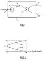
- FIG. 1illustrates a phase shift cell of an antenna according to the invention.
- Figure 2illustrates the use of the phase shift cell in Figure 1, which is inserted into the feed circuit of a four-wire antenna dipoles.
- Figure 4is a graph illustrating the variation of the power of two output signals of a phase shift cell as a function of a signal phase shift control applied to this cell.
- the electronic phase shifting means according to the inventionmake it possible to distribute the power (radiofrequency signals) delivered to the input (E) of the antenna 9 by a cable 13 to each of the radiating elements 5 to 8 (half-length dipole of wave in the case of an ATR antenna). This distribution is made using elementary phase shift cells 1 (FIG. 1).
- Each output S1, S2 of the two couplers respectively equipping the two phase shifters 1b, 1c,is connected to two radiating elements of antenna 9.
- coaxial cable 13which connects the antenna at the base station, all the electronics integrated into the antenna.
- modem 11can be connected to coaxial cable 13 to transmit the remote control information of the phase shifters delivered by a cellular network operation control device.
- Each phase shifter 3can be made up of a network of fixed elements switchable by diodes (or radio frequency relays) controlled digitally; such phase shifters are offered in particular by General Microwave Corp., Amityville, N.Y., U.S.A., and / or Narda Microwave, N.Y., U.S.A.
Landscapes
- Engineering & Computer Science (AREA)
- Computer Networks & Wireless Communication (AREA)
- Variable-Direction Aerials And Aerial Arrays (AREA)
- Waveguide Switches, Polarizers, And Phase Shifters (AREA)
Abstract
Description
Translated fromFrenchLa présente invention a pour objet, dans le domaine des antennespour réseaux de radiocommunications cellulaires terrestres, un procédéd'ajustage par télécommande de l'inclinaison (« tilt ») du diagramme derayonnement, par rapport à l'horizontale, des antennes d'une station debase.The subject of the present invention is, in the field of antennasfor terrestrial cellular radio networks, a methodadjustment by remote control of the tilt of the diagramradiation, with respect to the horizontal, of the antennas of a radio stationbased.
L'invention est également relative à une antenne équipée de moyensde réglage du « tilt », et à un système de commande à distance du « tilt ».The invention also relates to an antenna equipped with meanstilt adjustment system and a remote tilt control system.
Le domaine technique est celui des antennes actives (« smartantennas » ou « adaptive antennas ») pour les réseaux de communicationavec des terminaux mobiles de télécommunication.The technical field is that of active antennas (“smartantennas "or" adaptive antennas ") for communication networkswith mobile telecommunications terminals.
Un des problèmes rencontrés par les opérateurs de réseaux cellulaireslors de l'optimisation de leur réseau, est lié au contrôle de la couvertureradioélectrique offerte par chaque station de base. Un des moyens utiliséspour ajuster cette couverture consiste à modifier le tilt (inclinaison dudiagramme de rayonnement par rapport à l'horizontale) de l'antenne pourréduire (ou parfois accroítre) la portée d'une station de base ; lamodification du tilt est aussi utilisée pour réduire le brouillage occasionnépar une station de base desservant une cellule distante, dans laquelle lesmêmes ressources spectrales sont utilisées, afin d'accroítre la capacité duréseau.One of the problems faced by cellular network operatorswhen optimizing their network, is linked to monitoring coverageradio offered by each base station. One of the means usedto adjust this coverage consists in modifying the tilt (inclination of theradiation pattern with respect to the horizontal) of the antenna forreduce (or sometimes increase) the range of a base station; themodification of the tilt is also used to reduce the interference causedby a base station serving a remote cell, in which thesame spectral resources are used, in order to increase the capacity of thenetwork.
Aujourd'hui, dans un cas comme dans l'autre, il faut intervenir sur lesite (ce qui coûte cher puisqu'il faut faire intervenir un spécialiste del'installation des antennes) et ajuster de façon mécanique l'inclinaison decette antenne.Today, in one case as in the other, it is necessary to intervene on thesite (which is expensive since it involves a specialistantenna installation) and mechanically adjust the inclination ofthis antenna.
Le brevet US 4,249,181 (LEE) décrit un système de radiotéléphonemobile cellulaire, dans lequel des fréquences radio sont affectées à descellules disposées adjacentes pour former un réseau couvrant une zone deservice ; au moins un système d'antennes directionnelles est prévu danschaque cellule ; une antenne comporte plusieurs dipôles colinéairesalimentés en phase ; afin d'incliner l'axe d'un lobe du diagramme derayonnement de l'antenne dans un plan vertical, sous l'horizontale, l'antenne est fixée à un mat par l'intermédiaire d'un support mécaniqueincliné, fixe ou ajustable, afin d'augmenter l'efficacité de la couverture de lacellule desservie par l'antenne (par rapport au cas où l'axe seraithorizontal).US Patent 4,249,181 (LEE) describes a radiotelephone systemcellular mobile, in which radio frequencies are assigned tocells arranged adjacent to form a network covering an area ofservice; at least one directional antenna system is provided ineach cell; an antenna has several collinear dipolespowered in phase; in order to tilt the axis of a lobe of the diagramradiation of the antenna in a vertical plane, below the horizontal,the antenna is fixed to a mast by means of a mechanical supportinclined, fixed or adjustable, in order to increase the effectiveness of the cover of thecell served by the antenna (compared to the case where the axis ishorizontal).
Le réglage du tilt par le réglage d'un support mécanique d'antennenécessite une intervention sur site qui est coûteuse. Il est en outreimpossible avec ce système d'ajuster de façon précise la couvertureradioélectrique d'une cellule sans multiplier les interventions sur site.Adjusting the tilt by adjusting a mechanical antenna supportrequires an on-site intervention which is expensive. It is furtherimpossible with this system to precisely adjust the coverageof a cell without increasing the number of interventions on site.
Un tel dispositif mécanique de réglage d'inclinaison de l'antenneprésente également l'inconvénient de déformer le diagramme derayonnement de l'antenne dans le plan horizontal.Such a mechanical device for adjusting the inclination of the antennaalso has the disadvantage of distorting theradiation of the antenna in the horizontal plane.
Il est aussi possible d'utiliser des antennes dont le diagramme derayonnement est incliné par déphasage des signaux alimentant les antennesélémentaires qui composent l'antenne.It is also possible to use antennas whose diagram ofradiation is tilted by phase shift of the signals feeding the antennasthat make up the antenna.
La demande internationale WO 98/21779 (HUYNH) décrit uneantenne dont l'inclinaison du faisceau est variable électriquement ;l'antenne comporte des éléments rayonnants formant trois groupesd'éléments disposés le long d'un écran ; un mécanisme d'ajustement dephase est disposé entre le deuxième et le troisième groupe d'élémentsd'antenne, et comporte :
- un élément de couplage d'entrée ;
- une partie mobile de couplage dont une extrémité montée pivotanteest couplée électromagnétiquement à l'élément de couplage d'entrée ;
- une portion de ligne de transmission semi-circulaire qui est coupléeà une deuxième extrémité de la partie mobile ;
- un mécanisme d'entraínement de la partie mobile qui comporte unmoteur électrique commandable et contrôlable à distance.
- an input coupling element;
- a movable coupling part, one pivotally mounted end of which is electromagnetically coupled to the input coupling element;
- a portion of semicircular transmission line which is coupled to a second end of the movable part;
- a drive mechanism of the mobile part which includes an electric motor controllable and controllable remotely.
Les longueurs des chemins électriques à la fréquence defonctionnement sont telles que, lorsque la partie mobile est en positionmédiane, elles entraínent un déphasage progressif entre les élémentsrayonnants résultant en une inclinaison du diagramme de rayonnement de 7degrés environ sous l'horizontale ; cette inclinaison est réglable entre 0 et14 degrés par déplacement de la partie mobile (par le moteur), ce qui modifie la longueur des chemins électriques, et par conséquent la phaserelative des signaux délivrés aux éléments rayonnants.The lengths of the electrical paths at the frequency ofare such that when the moving part is in positionmedian, they cause a progressive phase shift between the elementsradiant resulting in an inclination of the radiation pattern of 7about degrees below the horizontal; this inclination is adjustable between 0 and14 degrees by displacement of the moving part (by the motor), whichchanges the length of the electrical paths, and therefore the phaserelative of the signals delivered to the radiating elements.
Ce dispositif électromécanique de déphasage est destiné à permettrede commander à distance l'inclinaison du diagramme de rayonnement, enparticulier en fonction de la variation d'intensité de la demande en périodede fin de semaine ou de vacances ; ce système présente certainsinconvénients : il ne permet pas une variation rapide du déphasage ; enoutre, sa fiabilité est limitée par celle du mécanisme électromécanique demodification de longueur des chemins électriques.This electromechanical phase shift device is intended to allowto remotely control the inclination of the radiation pattern, inparticular depending on the variation in intensity of demand during the periodweekend or vacation; this system presents somedisadvantages: it does not allow a rapid variation of the phase shift; inmoreover, its reliability is limited by that of the electromechanical mechanism ofmodification of the length of the electrical paths.
Un objectif poursuivi par l'invention est de proposer un dispositif devariation de l'inclinaison du diagramme de rayonnement d'une telleantenne, qui soit susceptible d'être commandé à distance, qui soit amélioréet remédie en partie au moins aux inconvénients des dispositifs connus.An objective pursued by the invention is to propose a device forvariation of the inclination of the radiation pattern of suchantenna, which can be remotely controlled, which is improvedand partially remedies at least the drawbacks of known devices.
Selon un premier aspect, l'invention consiste à proposer une antennepour réseau de télécommunication cellulaire terrestre, comprenant deséléments rayonnants et des moyens d'alimentation desdits élémentsrayonnants en signaux radiofréquence ; lesdits moyens d'alimentationcomprennent des moyens électroniques de déphasage entre lesdits signaux,de façon à permettre de régler à distance l'inclinaison du diagramme derayonnement dans un plan vertical, en particulier de l'axe du lobe principalde ce diagramme.According to a first aspect, the invention consists in proposing an antennafor terrestrial cellular telecommunications network, comprisingradiating elements and means for supplying said elementsradiating radio frequency signals; said supply meanscomprise electronic means of phase shift between said signals,so as to allow the inclination of the diagram to be adjusted remotelyradiation in a vertical plane, in particular of the axis of the main lobeof this diagram.
Les moyens électroniques de déphasage comportent une ou plusieurscellules de déphasage qui sont chacune généralement constituées par troiscomposants successivement disposés en série : un diviseur (ou répartiteur)par deux ; un circuit déphaseur statique connecté à une des deux sorties dudiviseur pour délivrer en sortie un signal déphasé ; un coupleur à deuxsorties en quadrature.The electronic phase shifting means comprise one or morephase shift cells which are each generally made up of threecomponents successively arranged in series: a divider (or distributor)by two ; a static phase shifter circuit connected to one of the two outputs of thedivider for outputting a phase shifted signal; a two couplerquadrature outputs.
Le circuit déphaseur statique est de préférence constitué par unréseau d'éléments déphaseurs fixes qui sont chacun associés à une diode (ouun relais radiofréquence) de commutation de l'élément déphaseur, laconduction des diodes (respectivement la fermeture des relais) pouvant êtrecommandée par un signal numérique de commande appliqué au circuit déphaseur ; le circuit comporte de préférence des diodes de commutationde type PIN.The static phase shifting circuit is preferably constituted by anetwork of fixed phase-shifting elements which are each associated with a diode (ora radio frequency relay) for switching the phase shifter element, theconduction of the diodes (respectively the closing of the relays) being able to becontrolled by a digital control signal applied to the circuitphase shifter; the circuit preferably includes switching diodesPIN type.
En utilisant un circuit déphaseur comportant deux, trois ou quatreéléments déphaseurs et leurs diodes (ou relais) associé(e)s, on dispose d'undéphaseur numérique 2, 3 ou 4 bits respectivement.Using a phase shifting circuit with two, three or fourphase shifting elements and their associated diodes (or relays), there is a2, 3 or 4 bit digital phase shifter respectively.
L'invention propose ainsi un dispositif très simple, précis, très fiable,compact et peu coûteux, facile à commander à distance, et qui permet defaire varier l'inclinaison du diagramme de rayonnement d'une antenne enmoins de 1 microseconde, en particulier lorsqu'on utilise des diodes, dontle temps de commutation très faible peut être de l'ordre de 10 à 100nanosecondes.The invention thus provides a very simple, precise, very reliable device,compact and inexpensive, easy to control remotely, and which allowsvary the inclination of the radiation pattern of an antenna byless than 1 microsecond, especially when using diodes, includingthe very short switching time can be of the order of 10 to 100nanoseconds.
Le dispositif selon l'invention provoque en outre peu de distorsiondu diagramme de rayonnement dans un plan horizontal.The device according to the invention also causes little distortionof the radiation pattern in a horizontal plane.
Afin de modifier le tilt de l'antenne, on insère dans le circuitd'alimentation radiofréquence de l'antenne des dispositifs électroniques(déphaseurs) qui vont permettre de faire basculer le diagramme derayonnement dans un plan vertical. Ce dispositif électronique peut êtretéléalimenté par le câble coaxial qui relie la station de base à l'antenne. Lacommande (numérique ou analogique) du dispositif électronique permetd'ajuster la valeur du tilt à une valeur prédéterminée par l'opérateur (parpas de 1 degré par exemple). On peut déporter cette commande au niveaude la station de base, voire au niveau de l'organe qui contrôle et assurel'exploitation du réseau cellulaire. La télécommande mise en place permetd'ajuster le tilt en temps réel sans intervention humaine sur l'antenne.In order to modify the tilt of the antenna, we insert into the circuitradio frequency feed to electronic devices(phase shifters) which will make it possible to switch the diagram ofradiation in a vertical plane. This electronic device can beremotely powered by the coaxial cable that connects the base station to the antenna. Thecontrol (digital or analog) of the electronic device allowsto adjust the tilt value to a value predetermined by the operator (bystep of 1 degree for example). We can deport this command to the levelfrom the base station, or even at the level of the body which controls and ensuresoperating the cellular network. The remote control installed allowsadjust the tilt in real time without human intervention on the antenna.
La possibilité d'ajuster le tilt de l'antenne à l'aide d'un dispositifélectronique permet, sur les réseaux cellulaires à accès multiple parrépartition dans le temps (type GSM), de contrôler l'inclinaison dudiagramme de rayonnement pour chaque intervalle de temps (trame), parvariation de l'inclinaison à une fréquence égale à l'inverse de la durée de latrame AMRT, donc terminal mobile par terminal mobile, en fonction desinformations de niveau reçu ou de qualité à l'interface radioélectrique. Leréglage du tilt pour chaque communication en cours peut être utilisé encomplément du contrôle de puissance pour ajuster le niveau du signal utile et pour réduire le niveau d'un signal brouilleur situé dans l'ouverture del'antenne.The possibility of adjusting the tilt of the antenna using a deviceelectronic allows, on cellular networks with multiple access bytime distribution (GSM type), to control the inclination of theradiation pattern for each time interval (frame), byvariation of the inclination at a frequency equal to the inverse of the duration of theTDMA frame, therefore mobile terminal by mobile terminal, according toreceived level or quality information at the radio interface. Thetilt adjustment for each call in progress can be used inadditional power control to adjust the level of the useful signaland to reduce the level of an interfering signal located in the opening ofthe antenna.
Un dispositif électronique de déphasage des antennes élémentairesest intégré à l'intérieur de chaque antenne. La commande de ce dispositifpermet d'ajuster le tilt de l'antenne. Lorsque la commande est déportée, unopérateur peut ajuster ce tilt sans intervention particulière sur l'antenne.Dans le cas où des mesures réalisées sur le réseau montrent que ce tilt doitêtre modifié pour réduire un brouillage ou pour modifier la couvertureradioélectrique, il est à nouveau possible de modifier le tilt sans coûtsupplémentaire.An electronic device for phase shifting of elementary antennasis integrated inside each antenna. The control of this deviceadjusts the tilt of the antenna. When the order is deported, aoperator can adjust this tilt without special intervention on the antenna.In the case where measurements made on the network show that this tilt mustbe modified to reduce interference or to change coverageradio, it is again possible to modify the tilt without costadditional.
Si toutes les antennes d'un réseau cellulaire sont équipées de cedispositif, il n'est plus nécessaire d'installer de dispositif d'inclinaison desantennes, ni d'indiquer au fabricant d'antennes s'il est nécessaire de fournirune antenne avec une valeur de tilt pré-déterminée.If all the antennas of a cellular network are equipped with thisdevice, it is no longer necessary to install a tilting deviceantennas, or to indicate to the antenna manufacturer whether it is necessary to providean antenna with a preset tilt value.
Les antennes des réseaux cellulaires sont utilisées la plupart du tempsen mode duplex (émission et réception sur la même antenne) ; le dispositifélectronique permet d'obtenir un tilt électrique identique sur la voiemontante et descendante.Cellular network antennas are used most of the timein duplex mode (transmission and reception on the same antenna); the deviceelectronic provides identical electrical tilt on the trackrising and falling.
Le dispositif électronique intégré dans le radôme de protection del'antenne est donc essentiellement composé de déphaseurs dont les signauxde commande peuvent être transmis par un câble coaxial transportant lessignaux radiofréquence à émettre. Du fait que la commande se fait sousforme numérique, il est possible d'intégrer la commande dans leséquipements du réseau cellulaire, après le début de l'utilisation del'antenne.The electronic device integrated in the protection radomethe antenna is therefore essentially composed of phase shifters whose signalscan be transmitted by a coaxial cable carrying theradio frequency signals to be transmitted. Because the order is made underdigital form, it is possible to integrate the command in thecellular network equipment, after the use ofthe antenna.
Ainsi, selon un autre aspect, l'invention consiste en un procédé decommande d'une pluralité d'antennes selon l'invention dans lequel ondélivre à chaque antenne un signal numérique de commande des moyensélectroniques de déphasage.Thus, according to another aspect, the invention consists of a method ofcontrol of a plurality of antennas according to the invention in which onedelivers to each antenna a digital signal for controlling the meanselectronic phase shift.
Selon des modes préférés de mise en oeuvre du procédé :
- le signal numérique de commande est transmis par un câble coaxialde transport des signaux radiofréquence ;
- la valeur d'inclinaison est ajustée périodiquement ;
- on commande par ledit signal numérique une variation del'inclinaison du diagramme à une fréquence égale à l'inverse de la durée dela trame AMRT, afin de contrôler l'inclinaison du diagramme dans chaquepériode de trame, pour chaque terminal mobile de télécommunicationdesservi par l'antenne, en fonction d'informations de niveau ou de qualitédu signal reçu par le terminal mobile.
- the digital control signal is transmitted by a coaxial cable for transporting radio frequency signals;
- the tilt value is adjusted periodically;
- said digital signal controls a variation of the inclination of the diagram at a frequency equal to the inverse of the duration of the TDMA frame, in order to control the inclination of the diagram in each frame period, for each mobile telecommunication terminal served by the antenna, based on level or quality information of the signal received by the mobile terminal.
Les avantages procurés par l'invention seront mieux compris autravers de la description suivante qui se réfère aux dessins annexés, quiillustrent sans aucun caractère limitatif des modes préférentiels deréalisation de l'invention.The advantages of the invention will be better understood fromthrough the following description which refers to the accompanying drawings, whichillustrate without any limiting character preferential modes ofrealization of the invention.
Dans les dessins, les éléments identiques ou similaires portent, saufindication contraire, les mêmes références d'une figure à l'autre.In the drawings, identical or similar elements bear, exceptotherwise indicated, the same references from one figure to another.
La figure 1 illustre une cellule de déphasage d'une antenne selonl'invention.FIG. 1 illustrates a phase shift cell of an antenna according tothe invention.
La figure 2 illustre l'utilisation de la cellule de déphasage de la figure1, qui est insérée dans le circuit d'alimentation d'une antenne à quatredipôles.Figure 2 illustrates the use of the phase shift cell in Figure1, which is inserted into the feed circuit of a four-wire antennadipoles.
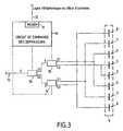
La figure 3 illustre schématiquement un dispositif d'inclinaison dudiagramme de rayonnement d'une antenne à huit dipôles comportant troiscellules de déphasage telles que celle illustrée figure 1.FIG. 3 schematically illustrates a device for tilting theradiation pattern of an eight-dipole antenna with threephase shift cells such as that illustrated in FIG. 1.
La figure 4 est un graphe illustrant la variation de la puissance desdeux signaux de sortie d'une cellule de déphasage en fonction d'un signalde commande de déphasage appliqué à cette cellule.Figure 4 is a graph illustrating the variation of the power oftwo output signals of a phase shift cell as a function of a signalphase shift control applied to this cell.
Les moyens électroniques de déphasage selon l'invention permettentde répartir la puissance (signaux radiofréquence) délivrée à l'entrée (E) del'antenne 9 par un câble 13 vers chacun des éléments rayonnants 5 à 8(dipôle demi-longueur d'onde dans le cas d'une antenne ATR). Cetterépartition est faite à l'aide de cellules 1 élémentaires de déphasage (figure1). Chaque cellule 1 se compose d'un « split tee » 2 (répartiteur par deux),d'un déphaseur 2 ou 3 bits (repère 3) et d'un coupleur (repère 4) à 3dbd'affaiblissement, à sorties (S1, S2) en quadrature, servant à alimenter deuxdipôles (5 ou 6 ou 7 ou 8) symétriques ; une première entrée du coupleur 4 est raccordée à la sortie du déphaseur 3 ; une deuxième entrée du coupleurest connectée à la sortie (non déphasée) du diviseur 2.The electronic phase shifting means according to the invention make it possible to distribute the power (radiofrequency signals) delivered to the input (E) of the
Lorsque la phase varie entre 0 et 90 degrés au niveau du déphaseur,la répartition de la puissance varie de la façon suivante (figure N°4) :
- pour un déphasage nul : la puissance d'entrée se répartit entre 50 %sur S1 et 50 % sur S2,
- pour 90 degrés de déphasage : la puissance d'entrée se répartit entre0 % sur S2 et 100 % sur S1.
- for a zero phase shift: the input power is distributed between 50% on S1 and 50% on S2,
- for 90 degrees of phase shift: the input power is distributed between 0% on S2 and 100% on S1.
En mettant en cascade des cellules élémentaires, on peut régler defaçon très fine le tilt de l'antenne. Deux exemples de réalisation sontdonnés pour une antenne composée de 8 dipôles élémentaires notamment(figure 3) ou de 4 dipôles (figure 2), mais le principe peut être étendu à uneantenne comprenant 16 ou 32 éléments rayonnants notamment.By cascading elementary cells, we can adjustvery fine tilt of the antenna. Two examples of realization aregiven for an antenna composed of 8 elementary dipoles in particular(Figure 3) or 4 dipoles (Figure 2), but the principle can be extended to aantenna comprising 16 or 32 radiating elements in particular.
Si l'on utilise des cellules de déphasage à 3 bits (soit 8 valeurs dedéphasage), on peut obtenir pour une antenne à 8 dipôles, 512 valeurs detilt pour le diagramme de rayonnement.If 3-bit phase shift cells are used (i.e. 8 values ofphase shift), for an antenna with 8 dipoles, 512 values oftilt for the radiation pattern.
Chaque sortie S1, S2 des deux coupleurs équipant respectivement lesdeux déphaseurs 1b, 1c, est connectée à deux éléments rayonnants del'antenne 9.Each output S1, S2 of the two couplers respectively equipping thetwo
Un circuit de commande 10 fournit à chacun des déphaseurs 1a, 1b,1c (figure 3) une combinaison binaire (3 bits dans l'exemple précédent)pour obtenir la valeur de tilt souhaitée. Le circuit de commande ainsi queles déphaseurs sont intégrés dans le radôme de l'antenne 9. Un modem 11permet de télécommander à distance les circuits de déphasage et donc derégler le tilt.A
Il est possible de téléalimenter par le câble coaxial 13, qui reliel'antenne à la station de base, toute l'électronique intégrée à l'antenne. Demême le modem 11 peut être raccordé au câble 13 coaxial pour transmettreles informations de télécommande des déphaseurs délivrées par undispositif de contrôle d'exploitation d'un réseau cellulaire.It is possible to remote supply by the
Chaque déphaseur 3 peut être constitué d'un réseau d'éléments fixescommutables par des diodes (ou des relais radiofréquence) commandéesnumériquement ; de tels déphaseurs sont proposés notamment par les Sociétés General Microwave Corp., Amityville, N.Y., U.S.A., et/ou NardaMicrowave, N.Y., U.S.A.Each
Claims (11)
Translated fromFrenchApplications Claiming Priority (2)
| Application Number | Priority Date | Filing Date | Title |
|---|---|---|---|
| FR9902587AFR2790142A1 (en) | 1999-02-24 | 1999-02-24 | ADJUSTABLE TILT ANTENNA |
| FR9902587 | 1999-02-24 |
Publications (1)
| Publication Number | Publication Date |
|---|---|
| EP1032074A1true EP1032074A1 (en) | 2000-08-30 |
Family
ID=9542724
Family Applications (1)
| Application Number | Title | Priority Date | Filing Date |
|---|---|---|---|
| EP00430009AWithdrawnEP1032074A1 (en) | 1999-02-24 | 2000-02-23 | Antenna with adjustable tilt |
Country Status (4)
| Country | Link |
|---|---|
| US (1) | US6366237B1 (en) |
| EP (1) | EP1032074A1 (en) |
| JP (1) | JP2000252735A (en) |
| FR (1) | FR2790142A1 (en) |
Cited By (6)
| Publication number | Priority date | Publication date | Assignee | Title |
|---|---|---|---|---|
| US7031751B2 (en) | 2001-02-01 | 2006-04-18 | Kathrein-Werke Kg | Control device for adjusting a different slope angle, especially of a mobile radio antenna associated with a base station, and corresponding antenna and corresponding method for modifying the slope angle |
| US7427962B2 (en) | 2003-06-16 | 2008-09-23 | Andrew Corporation | Base station antenna rotation mechanism |
| US7639196B2 (en) | 2001-07-10 | 2009-12-29 | Andrew Llc | Cellular antenna and systems and methods therefor |
| US7899496B2 (en) | 2000-07-10 | 2011-03-01 | Andrew Llc | Cellular antenna |
| US8018390B2 (en) | 2003-06-16 | 2011-09-13 | Andrew Llc | Cellular antenna and systems and methods therefor |
| CN103155623A (en)* | 2010-10-22 | 2013-06-12 | 瑞典爱立信有限公司 | Methods for cell selection balancing, computer programs and computer program products |
Families Citing this family (19)
| Publication number | Priority date | Publication date | Assignee | Title |
|---|---|---|---|---|
| US6667714B1 (en)* | 2000-05-03 | 2003-12-23 | Lucent Technologies Inc. | Downtilt control for multiple antenna arrays |
| KR20020041609A (en)* | 2000-11-28 | 2002-06-03 | 김상기 | Phase shifter for controlling beam tilt in wireless communication system |
| GB0125349D0 (en)* | 2001-10-22 | 2001-12-12 | Qinetiq Ltd | Antenna system |
| GB0311371D0 (en)* | 2003-05-17 | 2003-06-25 | Qinetiq Ltd | Phased array antenna system with adjustable electrical tilt |
| EP1642357B1 (en)* | 2003-05-17 | 2011-11-30 | Quintel Technology Limited | Phased array antenna system with adjustable electrical tilt |
| DE10328590A1 (en)* | 2003-06-25 | 2005-01-20 | Siemens Ag | Radio remote control for issuing commands to a remote-controlled device |
| DE10347414A1 (en)* | 2003-10-13 | 2005-05-04 | Bosch Gmbh Robert | Electronically tunable phase shifter |
| US7789936B2 (en)* | 2003-08-18 | 2010-09-07 | University Of Utah Research Foundation | Methods and systems for removing copper from ferrous scrap |
| DE10338536A1 (en)* | 2003-08-19 | 2005-04-07 | Bircher Reglomat Ag | Method for operating a radar sensor |
| EP1676338B1 (en)* | 2003-10-23 | 2017-12-06 | Telecom Italia S.p.A. | Antenna system and method for configuring a radiating pattern |
| US7177667B2 (en)* | 2003-11-25 | 2007-02-13 | Kmw Inc. | Antenna remote control apparatus of mobile communication base station system |
| US20050219133A1 (en)* | 2004-04-06 | 2005-10-06 | Elliot Robert D | Phase shifting network |
| GB0425813D0 (en)* | 2004-11-24 | 2004-12-29 | Finglas Technologies Ltd | Remote control of antenna line device |
| GB2485099B (en)* | 2007-08-31 | 2012-07-04 | Allen Vanguard Corp | Radio antenna assembly |
| WO2009026719A1 (en)* | 2007-08-31 | 2009-03-05 | Allen-Vanguard Technologies Inc. | Radio antenna assembly and apparatus for controlling transmission and reception of rf signals |
| US8027703B2 (en)* | 2009-02-11 | 2011-09-27 | Amphenol Corporation | Multi-beam antenna with multi-device control unit |
| US8831684B2 (en)* | 2010-11-22 | 2014-09-09 | Kathrein-Werke Kg | Base transceiver station with radiation beam steering and active antenna |
| US9294932B2 (en)* | 2011-07-21 | 2016-03-22 | Qualcomm Incorporated | Apparatus and method for wireless network enhancement via variable down tilt |
| CN107302137A (en)* | 2016-04-15 | 2017-10-27 | 安弗施无线射频系统(上海)有限公司 | Many long-range electric-regulating device, multi-frequency antenna device and Dual-polarized electricity regulating intelligent antenna devices |
Citations (7)
| Publication number | Priority date | Publication date | Assignee | Title |
|---|---|---|---|---|
| EP0443484A1 (en)* | 1990-02-23 | 1991-08-28 | Alcatel Telspace | Power link, protected by redundancy, for microwave signals |
| EP0624919A1 (en)* | 1992-12-01 | 1994-11-17 | Ntt Mobile Communications Network Inc. | Multi-beam antenna apparatus |
| WO1996014670A1 (en)* | 1994-11-04 | 1996-05-17 | Deltec New Zealand Limited | An antenna control system |
| WO1998021779A1 (en)* | 1996-11-13 | 1998-05-22 | Allen Telecom Inc. | Electrically variable beam tilt antenna |
| US5818385A (en)* | 1994-06-10 | 1998-10-06 | Bartholomew; Darin E. | Antenna system and method |
| WO1998048472A1 (en)* | 1997-04-18 | 1998-10-29 | Telefonaktiebolaget Lm Ericsson | A method for improving antenna performance parameters and an antenna arrangement |
| WO1999065262A2 (en)* | 1998-06-10 | 1999-12-16 | Telefonaktiebolaget Lm Ericsson (Publ) | Method and means for downlink antenna pattern downtilting |
Family Cites Families (9)
| Publication number | Priority date | Publication date | Assignee | Title |
|---|---|---|---|---|
| US4249181A (en) | 1979-03-08 | 1981-02-03 | Bell Telephone Laboratories, Incorporated | Cellular mobile radiotelephone system using tilted antenna radiation patterns |
| EP0647982B1 (en)* | 1993-08-12 | 2002-10-23 | Nortel Networks Limited | Base station antenna arrangement |
| GB2281012B (en)* | 1993-08-12 | 1998-04-15 | Northern Telecom Ltd | Angle diversity for multiple beam antenna |
| GB2281007B (en)* | 1993-08-12 | 1998-04-15 | Northern Telecom Ltd | Base station antenna arrangement |
| GB2281176B (en)* | 1993-08-12 | 1998-04-08 | Northern Telecom Ltd | Base station antenna arrangement |
| GB2281175B (en)* | 1993-08-12 | 1998-04-08 | Northern Telecom Ltd | Base station antenna arrangement |
| GB2281011B (en)* | 1993-08-12 | 1998-04-08 | Northern Telecom Ltd | Base station antenna arrangement |
| GB2281009B (en)* | 1993-08-12 | 1998-04-08 | Northern Telecom Ltd | Base station antenna arrangement |
| JP2626514B2 (en)* | 1993-11-08 | 1997-07-02 | 日本電気株式会社 | Base station transceiver |
- 1999
- 1999-02-24FRFR9902587Apatent/FR2790142A1/enactivePending
- 1999-05-04USUS09/304,385patent/US6366237B1/ennot_activeExpired - Fee Related
- 2000
- 2000-02-23EPEP00430009Apatent/EP1032074A1/ennot_activeWithdrawn
- 2000-02-23JPJP2000046379Apatent/JP2000252735A/enactivePending
Patent Citations (7)
| Publication number | Priority date | Publication date | Assignee | Title |
|---|---|---|---|---|
| EP0443484A1 (en)* | 1990-02-23 | 1991-08-28 | Alcatel Telspace | Power link, protected by redundancy, for microwave signals |
| EP0624919A1 (en)* | 1992-12-01 | 1994-11-17 | Ntt Mobile Communications Network Inc. | Multi-beam antenna apparatus |
| US5818385A (en)* | 1994-06-10 | 1998-10-06 | Bartholomew; Darin E. | Antenna system and method |
| WO1996014670A1 (en)* | 1994-11-04 | 1996-05-17 | Deltec New Zealand Limited | An antenna control system |
| WO1998021779A1 (en)* | 1996-11-13 | 1998-05-22 | Allen Telecom Inc. | Electrically variable beam tilt antenna |
| WO1998048472A1 (en)* | 1997-04-18 | 1998-10-29 | Telefonaktiebolaget Lm Ericsson | A method for improving antenna performance parameters and an antenna arrangement |
| WO1999065262A2 (en)* | 1998-06-10 | 1999-12-16 | Telefonaktiebolaget Lm Ericsson (Publ) | Method and means for downlink antenna pattern downtilting |
Non-Patent Citations (1)
| Title |
|---|
| WILSON G: "ELECTRICAL DOWNTILT THROUGH BEAM-STEERING VERSUS MECHANICAL DOWNTILT", FROM PIONEERS TO THE 21ST. CENTURY, DENVER, MAY 10 - 13, 1992, vol. 1, no. CONF. 42, 10 May 1992 (1992-05-10), INSTITUTE OF ELECTRICAL AND ELECTRONICS ENGINEERS, pages 1 - 4, XP000339669, ISBN: 0-7803-0673-2* |
Cited By (8)
| Publication number | Priority date | Publication date | Assignee | Title |
|---|---|---|---|---|
| US7899496B2 (en) | 2000-07-10 | 2011-03-01 | Andrew Llc | Cellular antenna |
| US7986973B2 (en) | 2000-07-10 | 2011-07-26 | Andrew Llc | Cellular antenna |
| US7031751B2 (en) | 2001-02-01 | 2006-04-18 | Kathrein-Werke Kg | Control device for adjusting a different slope angle, especially of a mobile radio antenna associated with a base station, and corresponding antenna and corresponding method for modifying the slope angle |
| US7366545B2 (en) | 2001-02-01 | 2008-04-29 | Kathrein Werke Kg | Control apparatus for changing a downtilt angle for antennas, in particular for a mobile radio antenna for a base station, as well as an associated mobile radio antenna and a method for changing the downtilt angle |
| US7639196B2 (en) | 2001-07-10 | 2009-12-29 | Andrew Llc | Cellular antenna and systems and methods therefor |
| US7427962B2 (en) | 2003-06-16 | 2008-09-23 | Andrew Corporation | Base station antenna rotation mechanism |
| US8018390B2 (en) | 2003-06-16 | 2011-09-13 | Andrew Llc | Cellular antenna and systems and methods therefor |
| CN103155623A (en)* | 2010-10-22 | 2013-06-12 | 瑞典爱立信有限公司 | Methods for cell selection balancing, computer programs and computer program products |
Also Published As
| Publication number | Publication date |
|---|---|
| FR2790142A1 (en) | 2000-08-25 |
| US6366237B1 (en) | 2002-04-02 |
| JP2000252735A (en) | 2000-09-14 |
Similar Documents
| Publication | Publication Date | Title |
|---|---|---|
| EP1032074A1 (en) | Antenna with adjustable tilt | |
| EP2532050B1 (en) | On-board directional flat-plate antenna, vehicle comprising such an antenna, and satellite telecommunication system comprising such a vehicle | |
| WO2011095384A1 (en) | Flat-plate scanning antenna for land mobile application, vehicle comprising such an antenna, and satellite telecommunication system comprising such a vehicle | |
| EP1246298B1 (en) | Multiband antenna for telecommunications | |
| WO2007010164A2 (en) | Antenna with adjustable radiating lobe configuration | |
| EP0771085A2 (en) | Method and system for transmitting radio electrical signals via a satellite network between a fixed earth station and mobile user terminals | |
| FR2749458A1 (en) | GEOSYNCHRONOUS SATELLITE TELECOMMUNICATIONS SYSTEM AND METHOD | |
| FR2778042A1 (en) | Satellite following transmit/receive mechanism | |
| FR2785476A1 (en) | Multiple beam wireless reception system has circular multiple beam printed circuit with beam switching mechanism, mounted on camera | |
| FR2622754A1 (en) | RADIO FREQUENCY OPTICAL TRANSMISSION SYSTEM, IN PARTICULAR IN THE FIELD OF SPACE TELECOMMUNICATIONS | |
| EP1723693B1 (en) | Antenna with variable misalignment comprising at least one phase-changing element | |
| FR2641657A1 (en) | COMMUNICATION DEVICE WITH MULTIPLE POWER SUPPLY, MULTIPLE CHANNELS | |
| FR2760919A1 (en) | MOBILE SATELLITE COMMUNICATION SYSTEM | |
| EP3503431A1 (en) | Method for multi-beam coverage by grouping basic beams of the same colour, and telecommunications payload for implementing such a method | |
| CA2290676A1 (en) | Telecommunication system antenna and method for transmitting and receiving using said antenna | |
| FR2793631A1 (en) | MULTMEDIA BIDIRECTIONAL COMMUNICATION TERMINAL | |
| FR2778802A1 (en) | CIRCULARLY POLARIZED MICROWAVE TRANSMISSION AND RECEPTION DEVICE | |
| WO1999000916A1 (en) | Telecommunication system | |
| EP1291962A1 (en) | Array beamformer for spacecraft | |
| EP1142063B1 (en) | Telecommunication device with shaped electronic scanning arrays and associated telecommunication terminal | |
| EP1058125B1 (en) | Antenna arrangement for reception of signals emitted by a geostationary satellite | |
| EP0464765A1 (en) | Space telecommunications system | |
| FR2778803A1 (en) | CIRCUIT AND METHOD FOR RECEIVING OR TRANSMITTING MICROWAVE WAVES | |
| FR2785488A1 (en) | Repeater for use with mobile telephones includes donor aerial and coverage aerial linked by repeater, with metal screen preventing unwanted aerial coupling | |
| CA2193573A1 (en) | Process and system for transmitting radioelectric signals between a stationary earth station and subscriber mobile terminals via a satellite network |
Legal Events
| Date | Code | Title | Description |
|---|---|---|---|
| PUAI | Public reference made under article 153(3) epc to a published international application that has entered the european phase | Free format text:ORIGINAL CODE: 0009012 | |
| AK | Designated contracting states | Kind code of ref document:A1 Designated state(s):AT BE CH CY DE DK ES FI FR GB GR IE IT LI LU MC NL PT SE | |
| AX | Request for extension of the european patent | Free format text:AL;LT;LV;MK;RO;SI | |
| 17P | Request for examination filed | Effective date:20000919 | |
| AKX | Designation fees paid | Free format text:AT BE CH CY DE DK ES FI FR GB GR IE IT LI LU MC NL PT SE | |
| 17Q | First examination report despatched | Effective date:20050318 | |
| 17Q | First examination report despatched | Effective date:20050318 | |
| STAA | Information on the status of an ep patent application or granted ep patent | Free format text:STATUS: THE APPLICATION IS DEEMED TO BE WITHDRAWN | |
| 18D | Application deemed to be withdrawn | Effective date:20070228 |