EP1028775B1 - Medical Introducing device with flared sheath end - Google Patents
Medical Introducing device with flared sheath endDownload PDFInfo
- Publication number
- EP1028775B1 EP1028775B1EP98956166AEP98956166AEP1028775B1EP 1028775 B1EP1028775 B1EP 1028775B1EP 98956166 AEP98956166 AEP 98956166AEP 98956166 AEP98956166 AEP 98956166AEP 1028775 B1EP1028775 B1EP 1028775B1
- Authority
- EP
- European Patent Office
- Prior art keywords
- sheath
- lead
- hub
- needle
- catheter
- Prior art date
- Legal status (The legal status is an assumption and is not a legal conclusion. Google has not performed a legal analysis and makes no representation as to the accuracy of the status listed.)
- Expired - Lifetime
Links
- 238000010008shearingMethods0.000claimsdescription7
- 238000011065in-situ storageMethods0.000abstract1
- 238000003780insertionMethods0.000description9
- 230000037431insertionEffects0.000description9
- 210000003462veinAnatomy0.000description7
- 210000005166vasculatureAnatomy0.000description6
- 239000004812Fluorinated ethylene propyleneSubstances0.000description4
- 210000001367arteryAnatomy0.000description4
- -1e.g.Substances0.000description4
- 238000000034methodMethods0.000description4
- 229920009441perflouroethylene propylenePolymers0.000description4
- 239000011347resinSubstances0.000description4
- 229920005989resinPolymers0.000description4
- BFKJFAAPBSQJPD-UHFFFAOYSA-NtetrafluoroetheneChemical groupFC(F)=C(F)FBFKJFAAPBSQJPD-UHFFFAOYSA-N0.000description4
- 239000004698PolyethyleneSubstances0.000description3
- 239000008280bloodSubstances0.000description3
- 210000004369bloodAnatomy0.000description3
- 239000004033plasticSubstances0.000description3
- 229920003023plasticPolymers0.000description3
- 229920000573polyethylenePolymers0.000description3
- 239000004809TeflonSubstances0.000description2
- 229920006362Teflon®Polymers0.000description2
- 230000005764inhibitory processEffects0.000description2
- 229920000642polymerPolymers0.000description2
- 238000012876topographyMethods0.000description2
- 239000000853adhesiveSubstances0.000description1
- 230000001070adhesive effectEffects0.000description1
- 238000005452bendingMethods0.000description1
- 239000002775capsuleSubstances0.000description1
- 210000000245forearmAnatomy0.000description1
- 239000000463materialSubstances0.000description1
- 238000000465mouldingMethods0.000description1
- 230000037361pathwayEffects0.000description1
- 230000003014reinforcing effectEffects0.000description1
- 229910001220stainless steelInorganic materials0.000description1
- 239000010935stainless steelSubstances0.000description1
- 230000001225therapeutic effectEffects0.000description1
- 239000012780transparent materialSubstances0.000description1
Images

Classifications
- A—HUMAN NECESSITIES
- A61—MEDICAL OR VETERINARY SCIENCE; HYGIENE
- A61M—DEVICES FOR INTRODUCING MEDIA INTO, OR ONTO, THE BODY; DEVICES FOR TRANSDUCING BODY MEDIA OR FOR TAKING MEDIA FROM THE BODY; DEVICES FOR PRODUCING OR ENDING SLEEP OR STUPOR
- A61M25/00—Catheters; Hollow probes
- A61M25/0097—Catheters; Hollow probes characterised by the hub
- A—HUMAN NECESSITIES
- A61—MEDICAL OR VETERINARY SCIENCE; HYGIENE
- A61M—DEVICES FOR INTRODUCING MEDIA INTO, OR ONTO, THE BODY; DEVICES FOR TRANSDUCING BODY MEDIA OR FOR TAKING MEDIA FROM THE BODY; DEVICES FOR PRODUCING OR ENDING SLEEP OR STUPOR
- A61M25/00—Catheters; Hollow probes
- A61M25/01—Introducing, guiding, advancing, emplacing or holding catheters
- A61M25/06—Body-piercing guide needles or the like
- A61M25/0662—Guide tubes
- A61M25/0668—Guide tubes splittable, tear apart
Definitions
- the present inventionrelates to an introducer device for insertion of a catheter, guide wire and the like into a patient. More particularly, the invention provides an improved introducer device comprising a splittable sheath component wherein the sheath comprises a flared end that significantly facilitates entry of a catheter, guide wire, etc. into the device.
- Splittable introducer deviceshave been employed for inserting catheters, guide wires and the like into patients.
- a typical procedureprovides for insertion of a dilator or needle encased within a splittable sheath into the vasculature of a patient. After insertion, the dilator or needle may be removed leaving the sheath protruding from the patient's vein.
- a diagnostic or therapeutic cathetere.g. a central venous access catheter or guide wire
- other objectsuch as a capsule is then threaded through the sheath into the patient.
- the encasing sheathis then longitudinally sheared and removed from the catheter or guide wire and the patient such as by applying opposing force to opposed wings or tabs of the introducer device. See U.S. Pat. Nos. 5,334,157; 5,221,263; 5,141,497; 5,098,392; 4,772,266; and 4,243,050; and WO 97/14456 and WO 97/14468.
- a catheter or guide wireinto an introducer device, particularly when using a small diameter catheter or guide wire.
- very small diameter catheterare employed in many applications, such as catheters having a diameter of 0.6 mm (0.026 inches) or less that are used for insertion into the vasculature of neonatal patients.
- catheters having a diameter of 0.6 mm (0.026 inches) or lessthat are used for insertion into the vasculature of neonatal patients.
- To introduce such a small, flexible tube into the small bore of the introducerrequires that the attending medical personnel to exercise significant manual dexterity.
- Certain prior introducer deviceshave been reported that include a hub or wing portions that contain a conical-type lead-in section that could facilitate entry of a guide wire or catheter into the bore of the device's sheath.
- the sheath componentis affixed to some point along the longitudinal axis and interior surface of the hub or wing portion(s) of the device.
- the top proximal end of the sheathnecessarily forms a shoulder or flange within the hub or wing portion(s), which flange can inhibit a catheter or guide wire passing through the device, particularly the leading edge of a catheter or guide wire.
- Such inhibitioncan cause bending of the catheter or guide wire that requires the ancillary medical device to be removed and then reinserted into the introducer.
- Such inhibition of an ancillary medical deviceis annoying and inconvenient to the medical personnel.
- U.S. Patent No. 4,510,674describes a catheter introducer which comprises a hollow sheath extending continuously from a base end portion thereof to a distal end portion thereof, and a hollow hub having a connection portion for connecting the hub to the sheath in such a manner that the hub and sheath partially overlap.
- a reinforcing coil bodyis fitted in the connection portion and extends axially of the sheath from the connection portion toward the distal end of the sheath to a point beyond the connection portion.
- the hubalso has a valve.
- An introducer slitter for facilitating the removal of an introducer or cannula from a catheter, pacing lead, or similar item as well as an introducer for use therewithis disclosed in European patent application No. 0 391 544. By slitting an introducer tube portion while the introducer tube is moved rearwardly relative to the catheter, the introducer does not have to be pulled over the proximal end of the catheter.
- U.S. Patent No. 5,221,263describes a catheter emplacement apparatus that comprises a sheath and a hub element with wings for removal from the catheter through application of opposing radial forces on score lines resulting in an axially splitting of the catheter emplacement apparatus into two pieces.
- the tubular sheathis rigidly bonded in the bore of a hub portion of an operating element and has a pair of diametrically opposed, longitudinal score lines.
- the hub elementis longitudinally divided by longitudinal slots aligned with the sheath score lines except for two thin walled integral connecting sections having score lines aligned with the sheath score lines.
- a pair of diametrically opposed, manually graspable wing portionsare integrally formed on the hub element intermediate the hub score lines to permit the longitudinal severance of the hub and sheath to remove same from a catheter traversing the bores of the hub element and sheath to enter the selected vein after the needle is removed.
- the present inventioncomprises an improved introducer device as specified in claim 1.
- the devicehas a sheath component that has a flared, preferably substantially conical-shaped end forming a lead-in section for facile introduction of an ancillary medical device, such as a catheter, guide wire, or the like.
- the sheathis typically adapted to snugly receive a dilator or needle for insertion in a vein or artery of a patient while circumscribed by the sheath.
- a continuous introduction pathwayis provided from the flared end into the lumen or bore of the introducer sheath that does not have any surface features that can arrest the forward travel of the end of an advancing catheter, guide wire or other ancillary medical device that may be inserted through the sheath.
- the introducer device of the inventionincludes: a sheath component comprising a bore and a flared introduction end, the sheath preferably being capable of being axially sheared and adapted to receive a dilator or percutaneous needle for insertion into a vein or artery of a patient while circumscribed by the sheath, and a hub unit attached to the sheath, the hub comprising two opposed wing portions attached to the sheath, the wing portions capable of splitting the sheath upon application of an effective shearing force to the wing portions.
- a dilator or needle for insertion into selected vasculature of a patientcan be circumscribed by the sheath.
- the wing portions of the deviceare disposed diametrically opposed to one another, each wing portion forming half of a lead-in section that can facilitate entry of a catheter, guide wire or other ancillary medical device.
- the hub unitunderlies the sheath lead-in portion, and the sheath lead-in portion is unattached to the underlying hub unit.
- the wing portionsdo not completely circumscribe the hub or the sheath component, but rather the wing portions are non-integral components that are separated, preferably on each of opposing sides, by the underlying sheath.
- the wing portionsare not split during shearing of the sheath, i.e. the sheath can be sheared along score lines formed in its surface interposed between the separated wing portions, thereby facilitating the shearing process.
- an improved introducer devicecontains a sheath component that has a flared proximal end that extends upwardly and above the proximal end of an attached hub component wherein that flared sheath proximal end provides a convenient lead-in section for entry of a dilator or percutaneous needle as well as ancillary medical devices inserted through the sheath such as a catheter or guide wire.
- proximal enddesignates herein the specified end closest to the medical personnel manipulating the introducer device
- distal enddesignates the specified end closest to the patient.
- flared proximal sheath endgenerally refers to a terminal portion of the sheath having an outwardly extending opening that is of greater diameter than the sheath body.
- a flared sheath endmay suitably have a convex shape, such as a taper. More typically, the flared end may be formed as a conical funnel end with an inside diameter graduating from an open end to the diameter of the sheath as generally shown in the Figures.
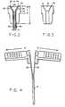
- FIG. 1Ashows introducer device 10 that includes splittable sheath component 12 having a bore adapted to receive hollow needle 16 that is inserted into a selected vein or artery of a patient.
- a hollow dilatoralso could take the place of needle 16, as shown in the corresponding device 10 of FIG. 1B.
- a hub unit 17, as shown in FIGS. 1A, 1B and 3,is formed as a convex shape for matingly underlying the flared end of the sheath.
- Two opposed wing or tab portions 18 and 20are attached to the hub 17. The wing portions 18 and 20 are diametrically opposed to each other as depicted in FIGS. 1A and 1B.
- the wings 18, 20are substantially L-shaped, and when mounted in diametrically opposed fashion on the sheath 12, result in a T-shaped configuration for the introducer 10.
- wing portions 18 and 20include topography to aid handling and manipulation of the introducer device.
- the exposed sides of wing portions 18 and 20have ridged gripping surfaces 24 or have other topography to facilitate handling and manipulation of device 10.
- a needle body portion 22is attached to the proximal end 16' of hollow needle 16.
- the needle body portionincludes an open-ended flash chamber 28 that receives blood flowing upward through bored needle 16 when sharpened distal end 16" pierces a patient's vein, thereby informing the medical personnel the needle has been successfully inserted.
- the distal end of needle body portion 22includes a narrow bore that is adapted to firmly engage needle 16.
- a bore within needle body portion 22expands to form flash chamber 28.
- the flash chambermay be molded of transparent material, e.g., plastic.
- This configurationenables the device to be more securely and conveniently placed on a patient (e.g. on the patient's forearm), and also facilitates access to and manipulation of proximal ends of needle 16 and needle body portion 22 by medical personnel.
- the needle body portion tapercommences at a position proximate to needle proximal end 16' as shown in FIG. 1A.
- a top lip 30 with luer threadsis formed on the outer surface of the proximal end of needle body portion 22 and is adapted to receive a syringe for administration to a patient via needle 16.
- Flash chamber 28may also include a luer taper within needle body portion 22.
- Sheath 12includes a flared proximal end forming a lead-in portion 34, preferably tapered or substantially cone shaped as shown in FIG. 3, and which aids insertion of a catheter, guide wire or the like into the bore of the splittable sheath.
- Hub unit 17comprises a convex sloping portion having a shape matingly underlying the lead-in portion 34, as can be seen clearly in FIG. 2.
- the wing portions 18 and 20are non-integral components, i.e. wings 18 and 20 are unattached with respect to each other, separated on each of opposing sides by the underlying splittable sheath portions 36 and 38 as can be seen in FIG. 4. As discussed above, by this configuration, the wing portions are not split during shearing of the sheath, thereby facilitating the shearing process.
- the splittable sheath 12 and its lead-in portion 34include axially extending, diametrically opposed score lines 40 and 42 to facilitate axial shearing upon imparting opposing divergent forces on wing portions 18 and 20. Score lines 40 and 42 should each traverse interposed lead-in portions 36 and 38, including the flared portions forming lead-in portion 34.
- FIG. 1Bshows a preferred introducer device of the invention, which is generally similar to the introducer device shown in FIG. 1A, except that a dilator 15 with distal tip 15" and proximal end hub 15' is employed and inserted through the sheath 12 during use of the device instead of a needle 16 as in the device of FIG. 1A.
- a dilator 15 with distal tip 15" and proximal end hub 15'is employed and inserted through the sheath 12 during use of the device instead of a needle 16 as in the device of FIG. 1A.
- elements of the device of FIG. 1B also depicted in FIG. 1Aare identified with corresponding reference numerals in FIG. 1B. Additionally, those elements, and preferred aspects thereof, are the same for the device of FIG. 1B as described above for the device of FIG. 1A.
- splittable sheath 12 and needle 16 or dilator 15should have a diameter capable of being inserted within selected vasculature of a patient, and sheath 12 should have a diameter sufficient to accommodate a catheter, guide wire or the like.
- the diameter of splittable sheath 12is between about 1 mm and 2.5 mm; and the diameter of needle 16 is between about 0.7 mm and 2 mm.
- the graduating lead-in portionmay suitably comprise from about 1 to 10 percent of the total length of the sheath, more typically about 2 to 6 percent of the sheath total length, although lead-in portions of a variety of lengths will be suitably.
- the lead-in portionmay suitably expand to a maximum diameter (at the lead-in portion proximal end) that is from about 1.5 to about 2, 3 or 4 times the diameter of the sheath (e.g. the diameter of the sheath as measured at the midpoint of the sheath length), although again lead-in portions of a variety of maximum diameters will be suitable to provide facilitated entry of needles, dilators, guide wires, catheters, etc.
- the diameter of the sheath(diameter p shown in FIG. 2) is about 2 mm; the maximum diameter of the sheath lead-in portion (diameter q in FIG. 2) is 5 mm; the length of the sheath including the lead-in portion (length r in FIG. 1A) is 4 cm; the length of the lead-in portion (length s in FIG. 2) is 3 mm; the width of a wing portion (width u in FIG 1A) is 1.6 cm; and the length of a wing portion (width v in FIG 2) is 1 cm.
- devices of substantially greater dimensionswill be usable, e.g. a device that is from 38 to 51cm (15 to 20 inches) or more in length depending on the intended application, as will be appreciated by those skilled in the art upon consideration of this disclosure.
- the diameters of a dilator as well as a sheath for circumscribing the dilatorwill be greater than the corresponding diameters of a device that employs a percutaneous needle instead of a dilator.
- an introducer device of the inventionmay be from a number of materials as will be appreciated by those skilled in the art.
- the sheath and hub uniteach are suitably formed from a polyethylene.
- the sheath(which includes the lead-in portion) is preferably from a fluorinated ethylene-propylene resin (FEP), and also could be formed from other fluorinated resins, e.g. a tetrafluoroethylene polymer such as TEFLON.
- FEPfluorinated ethylene-propylene resin
- a hollow needle 16is suitably fabricated from stainless steel as is known in the art.
- the needle body portion 22may be suitably rigid plastic such as a polyethylene, preferably with extended chamber 28 being substantially transparent so blood received therein can be readily observed.
- a dilator 15may be suitably formed from a polyethylene.
- a dilator 15is preferably formed from a fluorinated ethylene-propylene resin (FEP), and also could be formed from other fluorinated resins, e.g. a tetrafluoroethylene polymer such as TEFLON.
- FEPfluorinated ethylene-propylene resin
- the sheathcan be suitably formed in an insert molding process as is known in the art wherein the sheath is extruded with an expansion at one end to provide the integral lead-in portion, and then the hub unit with wing portions can be molded directly thereon.
- the hub unitalso can be separately formed and then attached, such as by a suitable adhesive. It is also possible to interpose a mounting unit such as a plastic strip between the hub unit and the sheath, although such an arrangement is generally less preferred.
- An introducer device of the inventionmay be suitably used as follows for placement of a catheter, guide wire or the like in a patient.
- a needle 16 or dilator 15is inserted into lead-in portion 34 such that tip sheath 16" or dilator tip 15" extends from the bore of the sheath 12 and a distal end thereof.
- the introducer device 10is inserted into a selected patient. If a needle 16 is employed, insertion of sharpened distal needle end 16" into a patient may be verified by blood flashback observed in chamber 28.
- Dilator 15may be suitably inserted into selected vasculature that has already been penetrated by another medical device.
- Needle 16 or dilator 15 with attached needle body portion 22suitably then may be withdrawn from the sheath 12, which remains in the vein or artery of the patient.
- a catheter or other medical devicethen can be introduced into lead-in portion 34 and threaded through the sheath component and into the vasculature.
- the lead-in portion 34 and the sheath 12is sheared by substantially opposite outward forces applied by the fingers in the directions Z and Z' depicted in FIG. 4. That outward force operates to shear the lead-in portion 34 and sheath 12 along the score lines thereof as discussed above.
Landscapes
- Health & Medical Sciences (AREA)
- Life Sciences & Earth Sciences (AREA)
- Biophysics (AREA)
- Pulmonology (AREA)
- Engineering & Computer Science (AREA)
- Anesthesiology (AREA)
- Biomedical Technology (AREA)
- Heart & Thoracic Surgery (AREA)
- Hematology (AREA)
- Animal Behavior & Ethology (AREA)
- General Health & Medical Sciences (AREA)
- Public Health (AREA)
- Veterinary Medicine (AREA)
- Media Introduction/Drainage Providing Device (AREA)
- Infusion, Injection, And Reservoir Apparatuses (AREA)
- Processing Of Meat And Fish (AREA)
- Paper (AREA)
Abstract
Description
Claims (2)
- A medical introducer device (10) comprising:(a) a splittable sheath (12) having a proximal end and a distal end and a bore adapted toreceive a dilator (15) or needle (16), the sheath proximal end having a flared lead-in portion(34) forming an outwardly convex shape converging from an open proximal end to the borefor aiding the introduction of an ancillary medical implement into the bore,(b) a hub unit (17) comprising at least two non-integral substantially L-shaped wingportions (18, 20) which are unattached with respect to each other and attached to opposingsides of the underlying sheath (12), resulting in a T-shaped configuration of the introducerdevice, each wing portion (18, 20) forming half of a convex hub lead-in section that underliesthe sheath lead-in portion (34),(c) the sheath lead-in portion (34) being unattached to the underlying hub unit andextending above the edge (17a) of the hub unit (17), and(d) the sheath (12) and the lead-in portion (34) including axially extending diametricallyopposed score lines (40, 42) to facilitate axial shearing upon imparting opposing divergentforces on the non-integral wing portions (18, 20).
- The introducer device of claim 1 wherein the wings (18, 20) are provided with rigidgripping surfaces.
Applications Claiming Priority (3)
| Application Number | Priority Date | Filing Date | Title |
|---|---|---|---|
| US961971 | 1997-10-31 | ||
| US08/961,971US5951518A (en) | 1997-10-31 | 1997-10-31 | Introducing device with flared sheath end |
| PCT/US1998/022473WO1999022804A1 (en) | 1997-10-31 | 1998-10-23 | Introducing device with flared sheath end |
Publications (3)
| Publication Number | Publication Date |
|---|---|
| EP1028775A1 EP1028775A1 (en) | 2000-08-23 |
| EP1028775A4 EP1028775A4 (en) | 2001-04-25 |
| EP1028775B1true EP1028775B1 (en) | 2005-05-25 |
Family
ID=25505250
Family Applications (1)
| Application Number | Title | Priority Date | Filing Date |
|---|---|---|---|
| EP98956166AExpired - LifetimeEP1028775B1 (en) | 1997-10-31 | 1998-10-23 | Medical Introducing device with flared sheath end |
Country Status (7)
| Country | Link |
|---|---|
| US (1) | US5951518A (en) |
| EP (1) | EP1028775B1 (en) |
| AT (1) | ATE296142T1 (en) |
| CA (1) | CA2307867C (en) |
| DE (1) | DE69830329T2 (en) |
| ES (1) | ES2242304T3 (en) |
| WO (1) | WO1999022804A1 (en) |
Families Citing this family (184)
| Publication number | Priority date | Publication date | Assignee | Title |
|---|---|---|---|---|
| US6159198A (en)* | 1998-07-16 | 2000-12-12 | Medtronic, Inc. | Introducer system |
| US6251119B1 (en)* | 1998-08-07 | 2001-06-26 | Embol-X, Inc. | Direct stick tear-away introducer and methods of use |
| AUPP550098A0 (en)* | 1998-08-26 | 1998-09-17 | Microcatheters Pty Ltd | Catheter guide |
| US6585703B1 (en)* | 1999-07-28 | 2003-07-01 | Span-America Medical Systems, Inc. | Dividable introducer catheter and positive-lock needle guard combination |
| US6363273B1 (en) | 1999-12-22 | 2002-03-26 | Codman & Shurtleff, Inc. | Introducer element and method of using same |
| US9579091B2 (en) | 2000-01-05 | 2017-02-28 | Integrated Vascular Systems, Inc. | Closure system and methods of use |
| US6942674B2 (en) | 2000-01-05 | 2005-09-13 | Integrated Vascular Systems, Inc. | Apparatus and methods for delivering a closure device |
| US8758400B2 (en) | 2000-01-05 | 2014-06-24 | Integrated Vascular Systems, Inc. | Closure system and methods of use |
| US6391048B1 (en) | 2000-01-05 | 2002-05-21 | Integrated Vascular Systems, Inc. | Integrated vascular device with puncture site closure component and sealant and methods of use |
| US7842068B2 (en) | 2000-12-07 | 2010-11-30 | Integrated Vascular Systems, Inc. | Apparatus and methods for providing tactile feedback while delivering a closure device |
| US6461364B1 (en) | 2000-01-05 | 2002-10-08 | Integrated Vascular Systems, Inc. | Vascular sheath with bioabsorbable puncture site closure apparatus and methods of use |
| USD450839S1 (en) | 2000-02-07 | 2001-11-20 | Larry G. Junker | Handle for introducer sheath |
| US6497681B1 (en) | 2000-06-02 | 2002-12-24 | Thomas Medical Products, Inc. | Device and method for holding and maintaining the position of a medical device such as a cardiac pacing lead or other intravascular instrument and for facilitating removal of a peelable or splittable introducer sheath |
| DE60144328D1 (en) | 2000-09-08 | 2011-05-12 | Abbott Vascular Inc | Surgical clamp |
| US6626918B1 (en) | 2000-10-06 | 2003-09-30 | Medical Technology Group | Apparatus and methods for positioning a vascular sheath |
| JP5190169B2 (en) | 2000-10-19 | 2013-04-24 | アプライド メディカル リソーシーズ コーポレイション | Surgical access instruments and methods |
| US6695867B2 (en) | 2002-02-21 | 2004-02-24 | Integrated Vascular Systems, Inc. | Plunger apparatus and methods for delivering a closure device |
| US7806904B2 (en) | 2000-12-07 | 2010-10-05 | Integrated Vascular Systems, Inc. | Closure device |
| US6623510B2 (en) | 2000-12-07 | 2003-09-23 | Integrated Vascular Systems, Inc. | Closure device and methods for making and using them |
| US7905900B2 (en) | 2003-01-30 | 2011-03-15 | Integrated Vascular Systems, Inc. | Clip applier and methods of use |
| US8690910B2 (en) | 2000-12-07 | 2014-04-08 | Integrated Vascular Systems, Inc. | Closure device and methods for making and using them |
| US7211101B2 (en) | 2000-12-07 | 2007-05-01 | Abbott Vascular Devices | Methods for manufacturing a clip and clip |
| US6494860B2 (en) | 2001-02-08 | 2002-12-17 | Oscor Inc. | Introducer with multiple sheaths and method of use therefor |
| IES20010547A2 (en) | 2001-06-07 | 2002-12-11 | Christy Cummins | Surgical Staple |
| EP2422829B1 (en) | 2001-08-14 | 2013-03-06 | Applied Medical Resources Corporation | Surgical access sealing apparatus |
| US20040073193A1 (en)* | 2002-10-15 | 2004-04-15 | Russ Houser | Guide wire insertion tool |
| US7192433B2 (en)* | 2002-03-15 | 2007-03-20 | Oscor Inc. | Locking vascular introducer assembly with adjustable hemostatic seal |
| US8137317B2 (en)* | 2002-03-15 | 2012-03-20 | Oscor Inc. | Locking vascular introducer assembly with adjustable hemostatic seal |
| WO2003101347A1 (en)* | 2002-05-31 | 2003-12-11 | Wilson-Cook Medical Inc. | Stent introducer apparatus |
| IES20030424A2 (en) | 2002-06-04 | 2003-12-10 | Robert Stevenson | Blood vessel closure clip and delivery device |
| EP2343032B1 (en) | 2002-06-05 | 2012-05-09 | Applied Medical Resources Corporation | Wound retractor |
| US7108710B2 (en) | 2002-11-26 | 2006-09-19 | Abbott Laboratories | Multi-element biased suture clip |
| US8202293B2 (en) | 2003-01-30 | 2012-06-19 | Integrated Vascular Systems, Inc. | Clip applier and methods of use |
| US8905937B2 (en) | 2009-02-26 | 2014-12-09 | Integrated Vascular Systems, Inc. | Methods and apparatus for locating a surface of a body lumen |
| US8398656B2 (en) | 2003-01-30 | 2013-03-19 | Integrated Vascular Systems, Inc. | Clip applier and methods of use |
| US8758398B2 (en) | 2006-09-08 | 2014-06-24 | Integrated Vascular Systems, Inc. | Apparatus and method for delivering a closure element |
| US8821534B2 (en) | 2010-12-06 | 2014-09-02 | Integrated Vascular Systems, Inc. | Clip applier having improved hemostasis and methods of use |
| US7857828B2 (en) | 2003-01-30 | 2010-12-28 | Integrated Vascular Systems, Inc. | Clip applier and methods of use |
| US20050020884A1 (en) | 2003-02-25 | 2005-01-27 | Hart Charles C. | Surgical access system |
| CA2533204A1 (en) | 2003-08-06 | 2005-02-17 | Applied Medical Resources Corporation | Surgical device with tack-free gel and method of manufacture |
| JP5069907B2 (en) | 2003-09-17 | 2012-11-07 | ジヤンセン・フアーマシユーチカ・ナームローゼ・フエンノートシヤツプ | Fused heterocyclic compounds |
| US7578803B2 (en) | 2004-03-18 | 2009-08-25 | C. R. Bard, Inc. | Multifunction adaptor for an open-ended catheter |
| US7854731B2 (en) | 2004-03-18 | 2010-12-21 | C. R. Bard, Inc. | Valved catheter |
| US7094218B2 (en) | 2004-03-18 | 2006-08-22 | C. R. Bard, Inc. | Valved catheter |
| US7594910B2 (en) | 2004-03-18 | 2009-09-29 | C. R. Bard, Inc. | Catheter connector |
| US8083728B2 (en) | 2004-03-18 | 2011-12-27 | C. R. Bard, Inc. | Multifunction adaptor for an open-ended catheter |
| US7594911B2 (en) | 2004-03-18 | 2009-09-29 | C. R. Bard, Inc. | Connector system for a proximally trimmable catheter |
| USD532513S1 (en) | 2004-03-19 | 2006-11-21 | Galt Medical Corporation | Handle for an introducer sheath |
| US7377915B2 (en) | 2004-04-01 | 2008-05-27 | C. R. Bard, Inc. | Catheter connector system |
| EP1740253B1 (en) | 2004-04-30 | 2008-08-13 | C.R.Bard, Inc. | Valved sheath introducer for venous cannulation |
| IES20040368A2 (en) | 2004-05-25 | 2005-11-30 | James E Coleman | Surgical stapler |
| US20060041230A1 (en)* | 2004-08-17 | 2006-02-23 | Davis Jeremy M | Over-the needle peel-away sheath catheter introducer |
| US8926564B2 (en) | 2004-11-29 | 2015-01-06 | C. R. Bard, Inc. | Catheter introducer including a valve and valve actuator |
| US8932260B2 (en) | 2004-11-29 | 2015-01-13 | C. R. Bard, Inc. | Reduced-friction catheter introducer and method of manufacturing and using the same |
| US9597483B2 (en) | 2004-11-29 | 2017-03-21 | C. R. Bard, Inc. | Reduced-friction catheter introducer and method of manufacturing and using the same |
| US8403890B2 (en) | 2004-11-29 | 2013-03-26 | C. R. Bard, Inc. | Reduced friction catheter introducer and method of manufacturing and using the same |
| US7462167B2 (en)* | 2005-01-26 | 2008-12-09 | Thomas Medical Products, Inc. | Catheter sheath slitter and method of use |
| US7875019B2 (en) | 2005-06-20 | 2011-01-25 | C. R. Bard, Inc. | Connection system for multi-lumen catheter |
| US8926633B2 (en) | 2005-06-24 | 2015-01-06 | Abbott Laboratories | Apparatus and method for delivering a closure element |
| US8313497B2 (en) | 2005-07-01 | 2012-11-20 | Abbott Laboratories | Clip applier and methods of use |
| US7598255B2 (en) | 2005-08-04 | 2009-10-06 | Janssen Pharmaceutica Nv | Pyrimidine compounds as serotonin receptor modulators |
| US9456811B2 (en) | 2005-08-24 | 2016-10-04 | Abbott Vascular Inc. | Vascular closure methods and apparatuses |
| US8920442B2 (en) | 2005-08-24 | 2014-12-30 | Abbott Vascular Inc. | Vascular opening edge eversion methods and apparatuses |
| US20070060895A1 (en) | 2005-08-24 | 2007-03-15 | Sibbitt Wilmer L Jr | Vascular closure methods and apparatuses |
| AU2006304141B2 (en) | 2005-10-14 | 2012-07-05 | Applied Medical Resources Corporation | Gel cap for wound retractor |
| US8808310B2 (en) | 2006-04-20 | 2014-08-19 | Integrated Vascular Systems, Inc. | Resettable clip applier and reset tools |
| USD611144S1 (en) | 2006-06-28 | 2010-03-02 | Abbott Laboratories | Apparatus for delivering a closure element |
| US8556930B2 (en) | 2006-06-28 | 2013-10-15 | Abbott Laboratories | Vessel closure device |
| CN101528298B (en)* | 2006-11-08 | 2012-11-21 | 心脏起搏器公司 | Separate hemostatic hub |
| WO2008141291A1 (en) | 2007-05-11 | 2008-11-20 | Applied Medical Resources Corporation | Surgical retractor with gel pad |
| US8226681B2 (en) | 2007-06-25 | 2012-07-24 | Abbott Laboratories | Methods, devices, and apparatus for managing access through tissue |
| US20090093752A1 (en) | 2007-10-05 | 2009-04-09 | Tyco Healthcare Group Lp | Seal anchor for use in surgical procedures |
| US8608702B2 (en) | 2007-10-19 | 2013-12-17 | C. R. Bard, Inc. | Introducer including shaped distal region |
| US8893947B2 (en) | 2007-12-17 | 2014-11-25 | Abbott Laboratories | Clip applier and methods of use |
| US20090157101A1 (en) | 2007-12-17 | 2009-06-18 | Abbott Laboratories | Tissue closure system and methods of use |
| US7841502B2 (en) | 2007-12-18 | 2010-11-30 | Abbott Laboratories | Modular clip applier |
| US20090187147A1 (en)* | 2008-01-22 | 2009-07-23 | Pressure Products Medical Supplies, Inc. | Apparatus and method for achieving micropuncture |
| US9282965B2 (en) | 2008-05-16 | 2016-03-15 | Abbott Laboratories | Apparatus and methods for engaging tissue |
| USD614296S1 (en)* | 2008-09-11 | 2010-04-20 | Ispg, Inc. | Needle hub |
| USD738500S1 (en) | 2008-10-02 | 2015-09-08 | Covidien Lp | Seal anchor for use in surgical procedures |
| CA2739910C (en) | 2008-10-13 | 2017-06-06 | Applied Medical Resources Corporation | Single port access system |
| US8398676B2 (en) | 2008-10-30 | 2013-03-19 | Abbott Vascular Inc. | Closure device |
| US8858594B2 (en) | 2008-12-22 | 2014-10-14 | Abbott Laboratories | Curved closure device |
| US8323312B2 (en) | 2008-12-22 | 2012-12-04 | Abbott Laboratories | Closure device |
| US9089311B2 (en) | 2009-01-09 | 2015-07-28 | Abbott Vascular Inc. | Vessel closure devices and methods |
| US9486191B2 (en) | 2009-01-09 | 2016-11-08 | Abbott Vascular, Inc. | Closure devices |
| US9173644B2 (en) | 2009-01-09 | 2015-11-03 | Abbott Vascular Inc. | Closure devices, systems, and methods |
| US9414820B2 (en) | 2009-01-09 | 2016-08-16 | Abbott Vascular Inc. | Closure devices, systems, and methods |
| US20100179589A1 (en) | 2009-01-09 | 2010-07-15 | Abbott Vascular Inc. | Rapidly eroding anchor |
| US20100185234A1 (en) | 2009-01-16 | 2010-07-22 | Abbott Vascular Inc. | Closure devices, systems, and methods |
| CN102802720B (en) | 2009-05-12 | 2015-11-25 | 埃克赛斯科技有限公司 | With the access to plant of valve |
| WO2010151825A1 (en) | 2009-06-26 | 2010-12-29 | C. R. Bard, Inc. | Proximally trimmable catheter including pre-attached bifurcation and related methods |
| US20110021877A1 (en)* | 2009-07-24 | 2011-01-27 | Tyco Healthcare Group Lp | Surgical port and frangible introducer assembly |
| US20110054492A1 (en) | 2009-08-26 | 2011-03-03 | Abbott Laboratories | Medical device for repairing a fistula |
| AU2011213558A1 (en) | 2010-02-08 | 2012-09-27 | Access Scientific, Inc. | Access device |
| US8303624B2 (en) | 2010-03-15 | 2012-11-06 | Abbott Cardiovascular Systems, Inc. | Bioabsorbable plug |
| US8758399B2 (en) | 2010-08-02 | 2014-06-24 | Abbott Cardiovascular Systems, Inc. | Expandable bioabsorbable plug apparatus and method |
| US8603116B2 (en) | 2010-08-04 | 2013-12-10 | Abbott Cardiovascular Systems, Inc. | Closure device with long tines |
| US8262619B2 (en) | 2010-09-30 | 2012-09-11 | Tyco Healthcare Group Lp | Introducer sheath for catheters |
| JP6396657B2 (en) | 2010-10-01 | 2018-09-26 | アプライド メディカル リソーシーズ コーポレイション | Natural orifice surgery system |
| US9289115B2 (en) | 2010-10-01 | 2016-03-22 | Applied Medical Resources Corporation | Natural orifice surgery system |
| US8753267B2 (en) | 2011-01-24 | 2014-06-17 | Covidien Lp | Access assembly insertion device |
| US8617184B2 (en) | 2011-02-15 | 2013-12-31 | Abbott Cardiovascular Systems, Inc. | Vessel closure system |
| US9149276B2 (en) | 2011-03-21 | 2015-10-06 | Abbott Cardiovascular Systems, Inc. | Clip and deployment apparatus for tissue closure |
| US8758236B2 (en) | 2011-05-10 | 2014-06-24 | Applied Medical Resources Corporation | Wound retractor |
| US8556932B2 (en) | 2011-05-19 | 2013-10-15 | Abbott Cardiovascular Systems, Inc. | Collapsible plug for tissue closure |
| US8753313B2 (en) | 2011-07-22 | 2014-06-17 | Greatbatch Ltd. | Introducer handle notch design/concept |
| EP2744557B1 (en) | 2011-08-17 | 2021-11-10 | Smiths Medical ASD, Inc. | Access device with valve |
| US9332976B2 (en) | 2011-11-30 | 2016-05-10 | Abbott Cardiovascular Systems, Inc. | Tissue closure device |
| US9271639B2 (en) | 2012-02-29 | 2016-03-01 | Covidien Lp | Surgical introducer and access port assembly |
| WO2014031914A1 (en)* | 2012-08-23 | 2014-02-27 | Alexander Mellon Eaton | Systems and methods for performing an injection |
| US9364209B2 (en) | 2012-12-21 | 2016-06-14 | Abbott Cardiovascular Systems, Inc. | Articulating suturing device |
| US9700703B2 (en)* | 2013-02-26 | 2017-07-11 | Coeur, Inc. | Guidewire insertion tool |
| JP2016512725A (en) | 2013-03-15 | 2016-05-09 | アプライド メディカル リソーシーズ コーポレイション | Mechanical gel surgical access instrument |
| US9566087B2 (en) | 2013-03-15 | 2017-02-14 | Access Scientific, Llc | Vascular access device |
| US20140330287A1 (en) | 2013-05-06 | 2014-11-06 | Medtronic, Inc. | Devices and techniques for anchoring an implantable medical device |
| US9220913B2 (en) | 2013-05-06 | 2015-12-29 | Medtronics, Inc. | Multi-mode implantable medical device |
| US9717923B2 (en) | 2013-05-06 | 2017-08-01 | Medtronic, Inc. | Implantable medical device system having implantable cardioverter-defibrillator (ICD) system and substernal leadless pacing device |
| US10532203B2 (en) | 2013-05-06 | 2020-01-14 | Medtronic, Inc. | Substernal electrical stimulation system |
| US10933230B2 (en) | 2013-05-06 | 2021-03-02 | Medtronic, Inc. | Systems and methods for implanting a medical electrical lead |
| US10556117B2 (en) | 2013-05-06 | 2020-02-11 | Medtronic, Inc. | Implantable cardioverter-defibrillator (ICD) system including substernal pacing lead |
| US10471267B2 (en) | 2013-05-06 | 2019-11-12 | Medtronic, Inc. | Implantable cardioverter-defibrillator (ICD) system including substernal lead |
| AU2014306232B2 (en) | 2013-08-05 | 2018-12-06 | C2Dx, Inc. | Medical devices having a releasable tubular member and methods of using the same |
| US10434307B2 (en) | 2013-10-15 | 2019-10-08 | Medtronic, Inc. | Methods and devices for subcutaneous lead implantation |
| US9610436B2 (en) | 2013-11-12 | 2017-04-04 | Medtronic, Inc. | Implant tools with attachment feature and multi-positional sheath and implant techniques utilizing such tools |
| US10792490B2 (en) | 2013-11-12 | 2020-10-06 | Medtronic, Inc. | Open channel implant tools and implant techniques utilizing such tools |
| US9974563B2 (en) | 2014-05-28 | 2018-05-22 | Cook Medical Technologies Llc | Medical devices having a releasable member and methods of using the same |
| US10064649B2 (en) | 2014-07-07 | 2018-09-04 | Covidien Lp | Pleated seal for surgical hand or instrument access |
| EP3169510B1 (en) | 2014-07-18 | 2018-10-03 | Applied Medical Resources Corporation | Method for manufacturing gels having permanent tack free coatings |
| WO2016022454A1 (en) | 2014-08-04 | 2016-02-11 | Darin Schaeffer | Medical devices having a releasable tubular member and methods of using the same |
| KR20240172766A (en) | 2014-08-15 | 2024-12-10 | 어플라이드 메디컬 리소시스 코포레이션 | Natural orifice surgery system |
| US10743960B2 (en) | 2014-09-04 | 2020-08-18 | AtaCor Medical, Inc. | Cardiac arrhythmia treatment devices and delivery |
| US9636505B2 (en) | 2014-11-24 | 2017-05-02 | AtaCor Medical, Inc. | Cardiac pacing sensing and control |
| US10328268B2 (en) | 2014-09-04 | 2019-06-25 | AtaCor Medical, Inc. | Cardiac pacing |
| DK3188793T3 (en) | 2014-09-04 | 2020-04-06 | Atacor Medical Inc | PACEMAKER CABLE CONTACT |
| US9636512B2 (en) | 2014-11-05 | 2017-05-02 | Medtronic, Inc. | Implantable cardioverter-defibrillator (ICD) system having multiple common polarity extravascular defibrillation electrodes |
| EP3215211A4 (en) | 2014-11-07 | 2018-07-04 | C. R. Bard, Inc. | Connection system for tunneled catheters |
| US9707011B2 (en) | 2014-11-12 | 2017-07-18 | Covidien Lp | Attachments for use with a surgical access device |
| US11097109B2 (en) | 2014-11-24 | 2021-08-24 | AtaCor Medical, Inc. | Cardiac pacing sensing and control |
| WO2016085930A2 (en) | 2014-11-25 | 2016-06-02 | Applied Medical Resources Corporation | Circumferential wound retraction with support and guidance structures |
| US11083491B2 (en) | 2014-12-09 | 2021-08-10 | Medtronic, Inc. | Extravascular implant tools utilizing a bore-in mechanism and implant techniques using such tools |
| US10729456B2 (en) | 2014-12-18 | 2020-08-04 | Medtronic, Inc. | Systems and methods for deploying an implantable medical electrical lead |
| US10349978B2 (en) | 2014-12-18 | 2019-07-16 | Medtronic, Inc. | Open channel implant tool with additional lumen and implant techniques utilizing such tools |
| US11027099B2 (en) | 2015-04-30 | 2021-06-08 | Smiths Medical Asd, Inc. | Vascular access device |
| US11026788B2 (en)* | 2015-08-20 | 2021-06-08 | Edwards Lifesciences Corporation | Loader and retriever for transcatheter heart valve, and methods of crimping transcatheter heart valve |
| US10368908B2 (en) | 2015-09-15 | 2019-08-06 | Applied Medical Resources Corporation | Surgical robotic access system |
| WO2017062850A2 (en) | 2015-10-07 | 2017-04-13 | Applied Medical Resources Corporation | Wound retractor with multi-segment outer ring |
| US10898690B2 (en) | 2016-03-22 | 2021-01-26 | The United States Of America As Represented By The Secretary Of The Air Force | Vascular access disassembling needle device and method |
| AU2017324450B2 (en) | 2016-09-12 | 2022-09-29 | Applied Medical Resources Corporation | Surgical robotic access system for irregularly shaped robotic actuators and associated robotic surgical instruments |
| CA3036822A1 (en)* | 2016-09-16 | 2018-03-22 | Surmodics, Inc. | Lubricious insertion tools for medical devices and methods for using |
| WO2018191547A1 (en) | 2017-04-14 | 2018-10-18 | Access Scientific, Llc | Vascular access device |
| US11160682B2 (en) | 2017-06-19 | 2021-11-02 | Covidien Lp | Method and apparatus for accessing matter disposed within an internal body vessel |
| US11896782B2 (en) | 2017-08-23 | 2024-02-13 | C. R. Bard, Inc. | Priming and tunneling system for a retrograde catheter assembly |
| US10828065B2 (en) | 2017-08-28 | 2020-11-10 | Covidien Lp | Surgical access system |
| US10675056B2 (en) | 2017-09-07 | 2020-06-09 | Covidien Lp | Access apparatus with integrated fluid connector and control valve |
| US10569059B2 (en) | 2018-03-01 | 2020-02-25 | Asspv, Llc | Guidewire retention device |
| US11737656B2 (en)* | 2018-06-01 | 2023-08-29 | PatCom Medical Inc. | Catheter and tube introducer |
| US11389193B2 (en) | 2018-10-02 | 2022-07-19 | Covidien Lp | Surgical access device with fascial closure system |
| US11457949B2 (en) | 2018-10-12 | 2022-10-04 | Covidien Lp | Surgical access device and seal guard for use therewith |
| US12285278B2 (en)* | 2018-12-13 | 2025-04-29 | Conmed Corporation | Protective vial for medical device |
| US11166748B2 (en) | 2019-02-11 | 2021-11-09 | Covidien Lp | Seal assemblies for surgical access assemblies |
| US10792071B2 (en) | 2019-02-11 | 2020-10-06 | Covidien Lp | Seals for surgical access assemblies |
| US11000313B2 (en) | 2019-04-25 | 2021-05-11 | Covidien Lp | Seals for surgical access devices |
| US11413068B2 (en) | 2019-05-09 | 2022-08-16 | Covidien Lp | Seal assemblies for surgical access assemblies |
| EP4527449A3 (en) | 2019-05-29 | 2025-04-30 | Atacor Medical, Inc. | Implantable electrical leads and associated delivery systems |
| US11357542B2 (en) | 2019-06-21 | 2022-06-14 | Covidien Lp | Valve assembly and retainer for surgical access assembly |
| US11259841B2 (en) | 2019-06-21 | 2022-03-01 | Covidien Lp | Seal assemblies for surgical access assemblies |
| US11259840B2 (en) | 2019-06-21 | 2022-03-01 | Covidien Lp | Valve assemblies for surgical access assemblies |
| US11413065B2 (en) | 2019-06-28 | 2022-08-16 | Covidien Lp | Seal assemblies for surgical access assemblies |
| US11399865B2 (en) | 2019-08-02 | 2022-08-02 | Covidien Lp | Seal assemblies for surgical access assemblies |
| US11523842B2 (en) | 2019-09-09 | 2022-12-13 | Covidien Lp | Reusable surgical port with disposable seal assembly |
| US11432843B2 (en) | 2019-09-09 | 2022-09-06 | Covidien Lp | Centering mechanisms for a surgical access assembly |
| US11812991B2 (en) | 2019-10-18 | 2023-11-14 | Covidien Lp | Seal assemblies for surgical access assemblies |
| US11464540B2 (en) | 2020-01-17 | 2022-10-11 | Covidien Lp | Surgical access device with fixation mechanism |
| US12324606B2 (en) | 2020-01-28 | 2025-06-10 | Covidien Lp | Seal assemblies for surgical access assemblies |
| US11576701B2 (en) | 2020-03-05 | 2023-02-14 | Covidien Lp | Surgical access assembly having a pump |
| US11446058B2 (en) | 2020-03-27 | 2022-09-20 | Covidien Lp | Fixture device for folding a seal member |
| US11717321B2 (en) | 2020-04-24 | 2023-08-08 | Covidien Lp | Access assembly with retention mechanism |
| US11529170B2 (en) | 2020-04-29 | 2022-12-20 | Covidien Lp | Expandable surgical access port |
| US11622790B2 (en) | 2020-05-21 | 2023-04-11 | Covidien Lp | Obturators for surgical access assemblies and methods of assembly thereof |
| US11666771B2 (en) | 2020-05-29 | 2023-06-06 | AtaCor Medical, Inc. | Implantable electrical leads and associated delivery systems |
| US11751908B2 (en) | 2020-06-19 | 2023-09-12 | Covidien Lp | Seal assembly for surgical access assemblies |
| AU2021320733A1 (en)* | 2020-08-03 | 2023-02-16 | Bard Access Systems, Inc. | Splittable needle and dilator catheter placement device and associated methods |
| EP4259254A1 (en) | 2020-12-21 | 2023-10-18 | Bard Access Systems, Inc. | Optimized structural support in catheter insertion systems |
Family Cites Families (43)
| Publication number | Priority date | Publication date | Assignee | Title |
|---|---|---|---|---|
| US862712A (en)* | 1907-02-13 | 1907-08-06 | James S Collins | Medical instrument. |
| US3537451A (en)* | 1966-10-26 | 1970-11-03 | Deseret Pharma | Intravenous catheter unit with releasable inserter means |
| US3788326A (en)* | 1970-07-29 | 1974-01-29 | H Jacobs | Distally perforated catheter for use in ventilating system |
| US3921631A (en)* | 1972-06-21 | 1975-11-25 | Vicra Sterile Inc | Catheter insertion device and method of catheter introduction |
| US3860006A (en)* | 1973-06-25 | 1975-01-14 | Kendall & Co | Suprapubic catheter system using an internal stylet |
| US4168709A (en)* | 1975-03-10 | 1979-09-25 | Bentov Itzhak E | Dilator |
| DE2715198C2 (en)* | 1976-04-15 | 1987-01-22 | Stofan O. Dipl.-Chem. Wien Tauschinski | Cannula for introducing a flexible vascular catheter into a blood vessel |
| US4243050A (en)* | 1977-12-13 | 1981-01-06 | Littleford Philip O | Method for inserting pacemaker electrodes and the like |
| US4233974A (en)* | 1978-09-05 | 1980-11-18 | Baxter Travenol Laboratories, Inc. | Spinal needle assembly |
| US4364391A (en)* | 1980-11-14 | 1982-12-21 | Toye Frederic J | Tracheostomy apparatus and method |
| US4585013A (en)* | 1981-04-20 | 1986-04-29 | Cordis Corporation | Lumenless pervenous electrical lead and method of implantation |
| JPS6171065A (en)* | 1984-09-13 | 1986-04-11 | テルモ株式会社 | Catheter introducer |
| US4596559A (en)* | 1984-11-02 | 1986-06-24 | Fleischhacker John J | Break-away handle for a catheter introducer set |
| US4802947A (en)* | 1986-07-16 | 1989-02-07 | Becton Dickinson And Company | Apparatus for attaching a catheter to a hub |
| GB8618253D0 (en)* | 1986-07-25 | 1986-09-03 | Wallace Ltd H G | Intermittent administration of therapeutic substance |
| US4793363A (en)* | 1986-09-11 | 1988-12-27 | Sherwood Medical Company | Biopsy needle |
| US4834708A (en)* | 1987-03-31 | 1989-05-30 | George Pillari | Puncture needle assembly |
| US4883468A (en)* | 1987-04-08 | 1989-11-28 | Terumo Kabushiki Kaisha | Medical tool introduction cannula and method of manufacturing the same |
| US4772266A (en)* | 1987-05-04 | 1988-09-20 | Catheter Technology Corp. | Catheter dilator/sheath assembly and method |
| US4983168A (en)* | 1989-01-05 | 1991-01-08 | Catheter Technology Corporation | Medical layered peel away sheath and methods |
| US5163903A (en)* | 1989-01-27 | 1992-11-17 | C. R. Bard, Inc. | Catheter exchange system with detachable luer fitting |
| US4997424A (en)* | 1989-04-05 | 1991-03-05 | Medamicus, Inc. | Catheter introducer and introducer slitter |
| US4973312A (en)* | 1989-05-26 | 1990-11-27 | Andrew Daniel E | Method and system for inserting spinal catheters |
| US5141497A (en)* | 1989-06-06 | 1992-08-25 | Becton, Dickinson And Company | Apparatus and method for an introducer |
| US5064414A (en)* | 1989-07-28 | 1991-11-12 | Angeion Corporation | Locking clip with sheath and dilator |
| US5290294A (en)* | 1990-04-17 | 1994-03-01 | Brian Cox | Method and apparatus for removal of a foreign body cavity |
| US5147336A (en)* | 1990-06-05 | 1992-09-15 | The Kendall Company | Adapter kit for a catheter introducer |
| US5290246A (en)* | 1991-01-18 | 1994-03-01 | Terumo Kabushiki Kaisha | Piercing needle |
| US5098392A (en)* | 1991-06-28 | 1992-03-24 | Fleischhacker John J | Locking dilator for peel away introducer sheath |
| US5167634A (en)* | 1991-08-22 | 1992-12-01 | Datascope Investment Corp. | Peelable sheath with hub connector |
| ATE191651T1 (en)* | 1992-01-07 | 2000-04-15 | Sherwood Serv Ag | CATHETER INTRODUCTION DEVICE |
| US5672158A (en)* | 1992-01-07 | 1997-09-30 | Sherwood Medical Company | Catheter introducer |
| US5279597A (en)* | 1992-01-13 | 1994-01-18 | Arrow International Investment Corp. | Catheter compression clamp |
| US5221263A (en)* | 1992-07-30 | 1993-06-22 | Gesco International, Inc. | Catheter emplacement apparatus |
| US5275583A (en)* | 1992-10-05 | 1994-01-04 | Lawrence Crainich | Trocar assembly with independently acting shield means |
| US5250033A (en)* | 1992-10-28 | 1993-10-05 | Interventional Thermodynamics, Inc. | Peel-away introducer sheath having proximal fitting |
| GB2274783B (en)* | 1993-02-03 | 1996-12-11 | Graham Cameron Grant | Intravenous infusion set with needle protection |
| US5391152A (en)* | 1993-03-12 | 1995-02-21 | C. R. Bard, Inc. | Catheter interlock assembly |
| US5334157A (en)* | 1993-09-09 | 1994-08-02 | Gesco International, Inc. | Catheter introducer |
| US5437645A (en)* | 1993-10-08 | 1995-08-01 | United States Surgical Corporation | Surgical instrument positioning device |
| US5489273A (en)* | 1994-10-07 | 1996-02-06 | Tfx Medical, Incorporated | Introducer device and methods of use thereof |
| US5741233A (en) | 1995-10-20 | 1998-04-21 | Tfx Medical, Incorporated | Introducer device and methods of use thereof |
| US5782807A (en)* | 1995-10-20 | 1998-07-21 | Tfx Medical Incorporated | Releasably locking introducer devices |
- 1997
- 1997-10-31USUS08/961,971patent/US5951518A/ennot_activeExpired - Lifetime
- 1998
- 1998-10-23ESES98956166Tpatent/ES2242304T3/ennot_activeExpired - Lifetime
- 1998-10-23DEDE69830329Tpatent/DE69830329T2/ennot_activeExpired - Lifetime
- 1998-10-23ATAT98956166Tpatent/ATE296142T1/ennot_activeIP Right Cessation
- 1998-10-23CACA002307867Apatent/CA2307867C/ennot_activeExpired - Fee Related
- 1998-10-23EPEP98956166Apatent/EP1028775B1/ennot_activeExpired - Lifetime
- 1998-10-23WOPCT/US1998/022473patent/WO1999022804A1/enactiveIP Right Grant
Also Published As
| Publication number | Publication date |
|---|---|
| DE69830329T2 (en) | 2006-02-02 |
| ATE296142T1 (en) | 2005-06-15 |
| WO1999022804A1 (en) | 1999-05-14 |
| US5951518A (en) | 1999-09-14 |
| ES2242304T3 (en) | 2005-11-01 |
| CA2307867C (en) | 2009-08-18 |
| EP1028775A1 (en) | 2000-08-23 |
| EP1028775A4 (en) | 2001-04-25 |
| DE69830329D1 (en) | 2005-06-30 |
| CA2307867A1 (en) | 1999-05-14 |
Similar Documents
| Publication | Publication Date | Title |
|---|---|---|
| EP1028775B1 (en) | Medical Introducing device with flared sheath end | |
| US5221263A (en) | Catheter emplacement apparatus | |
| US5167634A (en) | Peelable sheath with hub connector | |
| US4596559A (en) | Break-away handle for a catheter introducer set | |
| EP0162982B1 (en) | Catheter sheath | |
| US5328480A (en) | Vascular wire guiode introducer and method of use | |
| US4772266A (en) | Catheter dilator/sheath assembly and method | |
| US5188605A (en) | Separable insertion tool | |
| US5098392A (en) | Locking dilator for peel away introducer sheath | |
| US4650472A (en) | Apparatus and method for effecting percutaneous catheterization of a blood vessel using a small gauge introducer needle | |
| US8480628B2 (en) | Introducer apparatus | |
| US5873854A (en) | Method for percutaneous insertion of catheters | |
| US5489273A (en) | Introducer device and methods of use thereof | |
| US6592553B2 (en) | Introducer assembly and method therefor | |
| US6645178B1 (en) | Apparatus for inserting medical device | |
| US4412832A (en) | Peelable catheter introduction device | |
| JP2540025B2 (en) | Peel-away endoscopic retrograde cholangiography catheter | |
| US4411654A (en) | Peelable catheter with securing ring and suture sleeve | |
| AU652891B2 (en) | Lead introducer with mechanical opening valve | |
| EP1651299B1 (en) | Catheter tunneler adapter | |
| US7682337B2 (en) | Method and apparatus for gaining percutaneous access to a body | |
| US6500157B2 (en) | Intravenous infusion needle with soft body | |
| CA2577705A1 (en) | Catheter tunneler adapter |
Legal Events
| Date | Code | Title | Description |
|---|---|---|---|
| PUAI | Public reference made under article 153(3) epc to a published international application that has entered the european phase | Free format text:ORIGINAL CODE: 0009012 | |
| 17P | Request for examination filed | Effective date:20000525 | |
| AK | Designated contracting states | Kind code of ref document:A1 Designated state(s):AT BE CH CY DE DK ES FI FR GB GR IE IT LI LU MC NL PT SE | |
| A4 | Supplementary search report drawn up and despatched | Effective date:20010307 | |
| AK | Designated contracting states | Kind code of ref document:A4 Designated state(s):AT BE CH CY DE DK ES FI FR GB GR IE IT LI LU MC NL PT SE | |
| RIC1 | Information provided on ipc code assigned before grant | Free format text:7A 61M 39/00 A, 7A 61M 25/06 B, 7A 61M 25/00 B | |
| 17Q | First examination report despatched | Effective date:20021121 | |
| GRAP | Despatch of communication of intention to grant a patent | Free format text:ORIGINAL CODE: EPIDOSNIGR1 | |
| RTI1 | Title (correction) | Free format text:MEDICAL INTRODUCING DEVICE WITH FLARED SHEATH END | |
| GRAS | Grant fee paid | Free format text:ORIGINAL CODE: EPIDOSNIGR3 | |
| GRAA | (expected) grant | Free format text:ORIGINAL CODE: 0009210 | |
| AK | Designated contracting states | Kind code of ref document:B1 Designated state(s):AT BE CH CY DE DK ES FI FR GB GR IE IT LI LU MC NL PT SE | |
| PG25 | Lapsed in a contracting state [announced via postgrant information from national office to epo] | Ref country code:LI Free format text:LAPSE BECAUSE OF FAILURE TO SUBMIT A TRANSLATION OF THE DESCRIPTION OR TO PAY THE FEE WITHIN THE PRESCRIBED TIME-LIMIT Effective date:20050525 Ref country code:FI Free format text:LAPSE BECAUSE OF FAILURE TO SUBMIT A TRANSLATION OF THE DESCRIPTION OR TO PAY THE FEE WITHIN THE PRESCRIBED TIME-LIMIT Effective date:20050525 Ref country code:CH Free format text:LAPSE BECAUSE OF FAILURE TO SUBMIT A TRANSLATION OF THE DESCRIPTION OR TO PAY THE FEE WITHIN THE PRESCRIBED TIME-LIMIT Effective date:20050525 Ref country code:AT Free format text:LAPSE BECAUSE OF FAILURE TO SUBMIT A TRANSLATION OF THE DESCRIPTION OR TO PAY THE FEE WITHIN THE PRESCRIBED TIME-LIMIT Effective date:20050525 | |
| REG | Reference to a national code | Ref country code:GB Ref legal event code:FG4D | |
| REG | Reference to a national code | Ref country code:CH Ref legal event code:EP | |
| REG | Reference to a national code | Ref country code:IE Ref legal event code:FG4D | |
| REF | Corresponds to: | Ref document number:69830329 Country of ref document:DE Date of ref document:20050630 Kind code of ref document:P | |
| REG | Reference to a national code | Ref country code:SE Ref legal event code:TRGR | |
| PG25 | Lapsed in a contracting state [announced via postgrant information from national office to epo] | Ref country code:GR Free format text:LAPSE BECAUSE OF FAILURE TO SUBMIT A TRANSLATION OF THE DESCRIPTION OR TO PAY THE FEE WITHIN THE PRESCRIBED TIME-LIMIT Effective date:20050825 Ref country code:DK Free format text:LAPSE BECAUSE OF FAILURE TO SUBMIT A TRANSLATION OF THE DESCRIPTION OR TO PAY THE FEE WITHIN THE PRESCRIBED TIME-LIMIT Effective date:20050825 | |
| PG25 | Lapsed in a contracting state [announced via postgrant information from national office to epo] | Ref country code:CY Free format text:LAPSE BECAUSE OF FAILURE TO SUBMIT A TRANSLATION OF THE DESCRIPTION OR TO PAY THE FEE WITHIN THE PRESCRIBED TIME-LIMIT Effective date:20051023 | |
| PG25 | Lapsed in a contracting state [announced via postgrant information from national office to epo] | Ref country code:IE Free format text:LAPSE BECAUSE OF NON-PAYMENT OF DUE FEES Effective date:20051024 | |
| PG25 | Lapsed in a contracting state [announced via postgrant information from national office to epo] | Ref country code:PT Free format text:LAPSE BECAUSE OF FAILURE TO SUBMIT A TRANSLATION OF THE DESCRIPTION OR TO PAY THE FEE WITHIN THE PRESCRIBED TIME-LIMIT Effective date:20051027 | |
| PG25 | Lapsed in a contracting state [announced via postgrant information from national office to epo] | Ref country code:MC Free format text:LAPSE BECAUSE OF NON-PAYMENT OF DUE FEES Effective date:20051031 Ref country code:LU Free format text:LAPSE BECAUSE OF NON-PAYMENT OF DUE FEES Effective date:20051031 | |
| REG | Reference to a national code | Ref country code:ES Ref legal event code:FG2A Ref document number:2242304 Country of ref document:ES Kind code of ref document:T3 | |
| REG | Reference to a national code | Ref country code:CH Ref legal event code:PL | |
| PLBE | No opposition filed within time limit | Free format text:ORIGINAL CODE: 0009261 | |
| STAA | Information on the status of an ep patent application or granted ep patent | Free format text:STATUS: NO OPPOSITION FILED WITHIN TIME LIMIT | |
| ET | Fr: translation filed | ||
| 26N | No opposition filed | Effective date:20060228 | |
| REG | Reference to a national code | Ref country code:IE Ref legal event code:MM4A | |
| REG | Reference to a national code | Ref country code:FR Ref legal event code:PLFP Year of fee payment:18 | |
| REG | Reference to a national code | Ref country code:FR Ref legal event code:PLFP Year of fee payment:19 | |
| PGFP | Annual fee paid to national office [announced via postgrant information from national office to epo] | Ref country code:FR Payment date:20161025 Year of fee payment:19 Ref country code:GB Payment date:20161027 Year of fee payment:19 Ref country code:NL Payment date:20161026 Year of fee payment:19 Ref country code:DE Payment date:20161027 Year of fee payment:19 | |
| PGFP | Annual fee paid to national office [announced via postgrant information from national office to epo] | Ref country code:BE Payment date:20161027 Year of fee payment:19 Ref country code:SE Payment date:20161027 Year of fee payment:19 Ref country code:IT Payment date:20161024 Year of fee payment:19 Ref country code:ES Payment date:20161026 Year of fee payment:19 | |
| REG | Reference to a national code | Ref country code:DE Ref legal event code:R119 Ref document number:69830329 Country of ref document:DE | |
| REG | Reference to a national code | Ref country code:SE Ref legal event code:EUG | |
| REG | Reference to a national code | Ref country code:NL Ref legal event code:MM Effective date:20171101 | |
| GBPC | Gb: european patent ceased through non-payment of renewal fee | Effective date:20171023 | |
| REG | Reference to a national code | Ref country code:FR Ref legal event code:ST Effective date:20180629 | |
| PG25 | Lapsed in a contracting state [announced via postgrant information from national office to epo] | Ref country code:NL Free format text:LAPSE BECAUSE OF NON-PAYMENT OF DUE FEES Effective date:20171101 Ref country code:DE Free format text:LAPSE BECAUSE OF NON-PAYMENT OF DUE FEES Effective date:20180501 Ref country code:GB Free format text:LAPSE BECAUSE OF NON-PAYMENT OF DUE FEES Effective date:20171023 | |
| REG | Reference to a national code | Ref country code:BE Ref legal event code:MM Effective date:20171031 | |
| PG25 | Lapsed in a contracting state [announced via postgrant information from national office to epo] | Ref country code:SE Free format text:LAPSE BECAUSE OF NON-PAYMENT OF DUE FEES Effective date:20171024 Ref country code:BE Free format text:LAPSE BECAUSE OF NON-PAYMENT OF DUE FEES Effective date:20171031 Ref country code:FR Free format text:LAPSE BECAUSE OF NON-PAYMENT OF DUE FEES Effective date:20171031 | |
| PG25 | Lapsed in a contracting state [announced via postgrant information from national office to epo] | Ref country code:IT Free format text:LAPSE BECAUSE OF NON-PAYMENT OF DUE FEES Effective date:20171023 | |
| REG | Reference to a national code | Ref country code:ES Ref legal event code:FD2A Effective date:20181221 | |
| PG25 | Lapsed in a contracting state [announced via postgrant information from national office to epo] | Ref country code:ES Free format text:LAPSE BECAUSE OF NON-PAYMENT OF DUE FEES Effective date:20171024 |