EP1028650B1 - Apparatus for serial collection, storage and processing of biopsy specimens - Google Patents
Apparatus for serial collection, storage and processing of biopsy specimensDownload PDFInfo
- Publication number
- EP1028650B1 EP1028650B1EP98942284AEP98942284AEP1028650B1EP 1028650 B1EP1028650 B1EP 1028650B1EP 98942284 AEP98942284 AEP 98942284AEP 98942284 AEP98942284 AEP 98942284AEP 1028650 B1EP1028650 B1EP 1028650B1
- Authority
- EP
- European Patent Office
- Prior art keywords
- head
- catheter
- specimens
- biopsy
- cap
- Prior art date
- Legal status (The legal status is an assumption and is not a legal conclusion. Google has not performed a legal analysis and makes no representation as to the accuracy of the status listed.)
- Expired - Lifetime
Links
- 238000001574biopsyMethods0.000titleclaimsdescription72
- 238000003860storageMethods0.000titleclaimsdescription36
- 238000012545processingMethods0.000titleclaimsdescription25
- 238000005520cutting processMethods0.000claimsdescription32
- 238000012856packingMethods0.000claimsdescription12
- 238000000034methodMethods0.000claimsdescription9
- 239000012530fluidSubstances0.000claimsdescription7
- 229920003023plasticPolymers0.000claimsdescription7
- 238000001125extrusionMethods0.000claimsdescription3
- 239000002775capsuleSubstances0.000claims1
- 239000000834fixativeSubstances0.000description4
- 239000002184metalSubstances0.000description4
- 230000008901benefitEffects0.000description2
- 238000012986modificationMethods0.000description2
- 230000004048modificationEffects0.000description2
- 230000008569processEffects0.000description2
- 239000002904solventSubstances0.000description2
- 206010028980NeoplasmDiseases0.000description1
- 230000002009allergenic effectEffects0.000description1
- 230000004075alterationEffects0.000description1
- 238000004458analytical methodMethods0.000description1
- 238000013459approachMethods0.000description1
- 201000011510cancerDiseases0.000description1
- 230000000711cancerogenic effectEffects0.000description1
- 231100000315carcinogenicToxicity0.000description1
- 230000006835compressionEffects0.000description1
- 238000007906compressionMethods0.000description1
- 238000009826distributionMethods0.000description1
- 229920002457flexible plasticPolymers0.000description1
- 238000011065in-situ storageMethods0.000description1
- 208000015181infectious diseaseDiseases0.000description1
- 238000004519manufacturing processMethods0.000description1
- 239000000463materialSubstances0.000description1
- 238000000386microscopyMethods0.000description1
- 238000002559palpationMethods0.000description1
- 230000037361pathwayEffects0.000description1
- 238000002360preparation methodMethods0.000description1
- 230000002265preventionEffects0.000description1
- 230000001737promoting effectEffects0.000description1
- 238000005070samplingMethods0.000description1
- 239000007787solidSubstances0.000description1
- 238000010186stainingMethods0.000description1
- 239000000126substanceSubstances0.000description1
- 238000001356surgical procedureMethods0.000description1
- 238000012546transferMethods0.000description1
Images


Classifications
- A—HUMAN NECESSITIES
- A61—MEDICAL OR VETERINARY SCIENCE; HYGIENE
- A61B—DIAGNOSIS; SURGERY; IDENTIFICATION
- A61B10/00—Instruments for taking body samples for diagnostic purposes; Other methods or instruments for diagnosis, e.g. for vaccination diagnosis, sex determination or ovulation-period determination; Throat striking implements
- A61B10/02—Instruments for taking cell samples or for biopsy
- A—HUMAN NECESSITIES
- A61—MEDICAL OR VETERINARY SCIENCE; HYGIENE
- A61B—DIAGNOSIS; SURGERY; IDENTIFICATION
- A61B10/00—Instruments for taking body samples for diagnostic purposes; Other methods or instruments for diagnosis, e.g. for vaccination diagnosis, sex determination or ovulation-period determination; Throat striking implements
- A61B10/0096—Casings for storing test samples
- A—HUMAN NECESSITIES
- A61—MEDICAL OR VETERINARY SCIENCE; HYGIENE
- A61B—DIAGNOSIS; SURGERY; IDENTIFICATION
- A61B10/00—Instruments for taking body samples for diagnostic purposes; Other methods or instruments for diagnosis, e.g. for vaccination diagnosis, sex determination or ovulation-period determination; Throat striking implements
- A61B10/02—Instruments for taking cell samples or for biopsy
- A61B10/06—Biopsy forceps, e.g. with cup-shaped jaws
- A—HUMAN NECESSITIES
- A61—MEDICAL OR VETERINARY SCIENCE; HYGIENE
- A61B—DIAGNOSIS; SURGERY; IDENTIFICATION
- A61B10/00—Instruments for taking body samples for diagnostic purposes; Other methods or instruments for diagnosis, e.g. for vaccination diagnosis, sex determination or ovulation-period determination; Throat striking implements
- A61B10/02—Instruments for taking cell samples or for biopsy
- A61B10/0233—Pointed or sharp biopsy instruments
- A61B10/0266—Pointed or sharp biopsy instruments means for severing sample
- A—HUMAN NECESSITIES
- A61—MEDICAL OR VETERINARY SCIENCE; HYGIENE
- A61B—DIAGNOSIS; SURGERY; IDENTIFICATION
- A61B10/00—Instruments for taking body samples for diagnostic purposes; Other methods or instruments for diagnosis, e.g. for vaccination diagnosis, sex determination or ovulation-period determination; Throat striking implements
- A61B10/02—Instruments for taking cell samples or for biopsy
- A61B10/0233—Pointed or sharp biopsy instruments
- A61B10/0283—Pointed or sharp biopsy instruments with vacuum aspiration, e.g. caused by retractable plunger or by connected syringe
- A—HUMAN NECESSITIES
- A61—MEDICAL OR VETERINARY SCIENCE; HYGIENE
- A61B—DIAGNOSIS; SURGERY; IDENTIFICATION
- A61B10/00—Instruments for taking body samples for diagnostic purposes; Other methods or instruments for diagnosis, e.g. for vaccination diagnosis, sex determination or ovulation-period determination; Throat striking implements
- A61B10/02—Instruments for taking cell samples or for biopsy
- A61B2010/0225—Instruments for taking cell samples or for biopsy for taking multiple samples
Definitions
- This inventionrelates generally to a method and devices for the serial collection, storage, and processing of biopsy specimens for microscopic, chemical, or other types of examination.
- the inventionrelates to biopsy sampling or removing tissue from any remote luminal structure within a patient, and storing the tissue within the removal apparatus in the order sampled through analysis or processing.
- tissue samples for examination from deep within luminal structurescan only be retrieved by catheterization methods using endoscopic or fluoroscopic control, or by blind palpation.
- the biopsy devices used for these techniquesremove 1 to 4 specimens that are retrieved by removing the biopsy instrument from the patient, and placing the specimen in a container of fixative solution labeled with the biopsy site and patient identification.
- the biopsies obtained in each passare processed in a batch, since the minute pieces cannot be easily separated. Consequently, biopsies from different sites must be handled separately, thus requiring considerable effort and expense.
- the need to perform multiple biopsy passes because of the limited storage capacity of the biopsy instrument and the need to identify the sites of biopsy originprolongs the procedure and may even cause it to fail, if the position of the biopsy instrument cannot be reacquired.
- the batch of containers for each patientis then transported to the laboratory where the containers are serially opened and the specimens transferred to numbered cassettes that are recorded for later identification.
- the cassettesare then processed for examination.
- the processed specimensare then sliced, stained and mounted on labeled slides for microscopic examination.
- the specimens in each containermust be processed separately to maintain identification. This is particularly important when the distribution and extent of a cancer is being mapped to determine the possibility of surgical removal and to prevent errors in reporting.
- One embodiment of the present inventionmodifies biopsy instruments for capture of each biopsy serially and provides for storage within the biopsy instrument.
- the storage chamberis designed to be removed from the instrument shaft and closed to serve as a processing cassette without specimen handling, until the specimens are sliced for mounting and staining prior to microscopy, or analyzed chemically.
- a device for obtaining tissue samples from remote locations within a patientcomprises an elongated flexible member having a lumen, a distal end, and a proximal end.
- a cutting meansis located near the distal end of the elongated member. The cutting means is actuated to cut tissue when the elongated member is moved toward the head or when the cutting distal head is moved toward the flexible member.
- An example of this type of deviceis shown in PCT Application WO 93/04630.
- the present inventionmodifies this device by providing storage means within the device and closing means for creating a cassette for storing and processing the specimens in the order they were collected.
- the cutting headserves as a packing means to force each biopsy into the shaft for storage.
- the elongated membermay serve as the cutting means and the head an anvil.
- the biopsiescan be stored within the head.
- the headis perforated to allow for fluid flow through the head.
- Each specimenis forced into the perforated head storage chamber by injecting fluid through the shaft before the cutting means and anvil are opened for the subsequent biopsy.
- the storage head containing the specimensis cut from the actuating shaft and closed with a perforated cap.
- the biopsy device headhas now become a processing cassette with serial biopsies enclosed in order of acquisition, and ready for fixation and processing without further handling.
- the headcan have a perforated flap that can be peeled open to allow for easy removal of the biopsy specimens.
- the cutting meanscan thus be located either on the head or the elongated member, and storage of the specimens can take place in either the head or the elongated member.
- a biopsy device for obtaining tissue samples from remote locations within a patientcomprises a flexible plastic catheter or shaft with one or two side lumens and a relatively large central lumen.
- the distal endcontains a remotely controllable folded spring jaw biopsy device within the central lumen that is stabilized by metal or plastic guides.
- the guidesenlarge the lumen and ensure that there is sufficient room to store the collected biopsy specimens as compared to a solid plastic extrusion with only a slot as a guide. It also enables the use of a simple extruded catheter for the device.
- the folded spring jawis extended proximally to form a chamber within the catheter to receive the specimens.
- the junction of the chamber and the folded spring jawis angulated to increase the distance between the jaws when they are extended and also to form a constriction at the distal most extent of the chamber.
- the actuator cableis biased to limit extension of the folded spring to the angled jaws distal to the constriction.
- the constriction and holding chamberremain within the catheter and prevent loss of the stored biopsies. As the spring jaws are drawn into the catheter with each new biopsy, the constriction is reduced, allowing the latest specimen to be aspirated into the holding chamber.
- the side lumen(s)have open slits to carry suction from the proximal end of the catheter to draw the specimens into the chamber after each biopsy.
- the distal end of the apparatusis capped after withdrawal.
- the catheteris cut at a marked site proximal to the specimen holding chamber and capped with a second cap.
- Perforated capsallow fixation and processing of the specimens within the chamber.
- the catheterhas thus become a processing cassette with the serial specimens enclosed in order of acquisition and ready for fixation and processing without further handling.
- Plastic or metal guidesare preferably inserted into the central lumen of the catheter to support and prevent twisting of the folded spring and to create a chamber for the storage of biopsies.
- the closed shaftis cut open and the biopsies are ready for slicing, still remaining in order of acquisition.
- a single log prepared at the time of biopsyserves to identify each specimen to the submitter and laboratory, and for reporting without handling, risk of biopsy loss or documentation error.
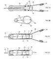
- FIGS. 1 through 4there is illustrated several embodiments of the device according to the invention, which permits serial specimen collection, storage and processing.
- a biopsy obtained with this methodis cut as blade 12 approaches anvil 13. Therefore, the distance between blade 12 and anvil 13, which is determined by the distance moved by actuator cable 15, is the major determinant of specimen length.
- Biopsy widthis constrained by actuator cable 15 to approximately 50% of the diameter of cutting blade 12.
- specimen 11is forced into the cutting chamber and cannot escape except into either the receptacle head, shown in FIGS. 3A-3B and 4A-4C, or shaft shown in FIGS. 1A, 1B and 2.
- These external constraintscombined with a conical packing shaft 18 within the head 20, provide the force to align, pack, and maintain specimen position as well as prevent loss of the specimen 11 when shaft 10 and head 20 are drawn apart for additional biopsies.
- the force to align, pack, and store the biopsiesmust be provided by the instrument itself.
- biopsy sizeis important and a minimum specimen length of twice the blade diameter is assumed to align specimens within the storage space and prevent mixing. This is provided by calibrating shaft movement to that minimum distance. Packing of specimen 11 into shaft 10 and prevention of loss is accomplished by conical packing shaft 18 attached to cutting head 20 that extends into shaft 10 so that packed specimens are constrained.
- the procedure described aboveallows the operator to collect and store the specimens in the sequence of acquisition, and allows hands-off processing of the specimens without loss of sequence.
- the lateral biopsy deviceprovides for either a cutting head, shown in FIG. 1A, or cutting shaft, shown in FIG. 2. Either of these parts may be used as the receptacle for serial specimens that may then be processed in situ.
- a stopper 40is placed within shaft 10 and connected to wire 15. Stopper 40 is preferably perforated and serves as an end point to the storage chamber formed by shaft 10.
- head 20is removed from shaft 10.
- Wire 15is cut and led through a perforated cap 30, which is placed over the open end of shaft 10, as shown in FIG. 1B. Wire 15 is then pulled from cap 30 to raise stopper 40 and compress specimens 11 within shaft 10.
- FIGS. 1A and 1Bshow a perforated stopper 40 that limits the movement of specimens 11 up shaft 10, determines the length of the storage space, number of biopsies that can be stored, and provides a proximal cap after shaft 10 is cut.
- the distal perforated cap 30is also shown in FIG. 1B. The application of both stopper 40 and cap 30 provides a sealed storage cassette for specimens 11.
- the length of the shaft containing the biopsies to be processedcan be determined by measuring the length of wire outside the cap after the wire is pulled through the cap. Shaft 10 can then be cut to this length to create a compact processing cassette for specimens 11.
- the perforated cap 30 and stopper 40allow for exposure of specimens 11 during storage and processing.
- the cutting blade 22is on shaft 10 instead of in head 20.
- Cutting blade 22cuts specimens 11 when head 20 containing anvil 23 is brought down onto blade 22.
- Packing head 18compresses specimens 11 into shaft 10 for storage. Placement of cap 30 and further compression of specimens 11 proceeds as with the device shown in FIGS. 1A and 1B, above.
- specimens 11can be stored in head 50, as shown in FIGS. 3 and 4.
- FIGS. 3A and 3Bshow the device according to the invention, wherein head 50 is hollow and serves as the storage chamber for specimens 11. Similar to the device shown in FIG. 1A, cutting blade 12 is located on head 50, and serves to cut specimens 11 when it is brought down onto anvil 13.
- cutting head 50is a cylindrical space made of metal or plastic with a proximal facing blade. If the head is hollow, cut specimens may be stored within this space.
- the headspacehas a direct relationship to its diameter, length and the size of the sample.
- the head diametermust conform to the shaft diameter. Head length is limited by the rigidity produced by head length that impedes maneuverability of the device. Head length must be limited, generally, to between 2 and 4 times shaft diameter to allow easy passage of the device around curves in the endoscope or passage that is to be traversed. The possibility of special cases remains.
- the catheteris 7 French or 2.3 mm in diameter, with a head length twice the diameter of the shaft of 4.6 mm, will only store 5-6 specimens.
- Increasing head length to 3 times diameter or 7mmincreases storage capacity to 10.
- Further increases in head length to 4, 5, or 6 times the shaft diameterincreases biopsy storage capacity to 13, 16, and 20 specimens, respectively, but at the cost of a longer rigid tip that progressively prevents accurate positioning and limits maneuverability.
- Head 50is preferably perforated to allow for packing of the specimens 11 within head 50 by injecting fluid through shaft 10 into head 50.
- the fluid pressurecauses specimens 11 to be compressed into head 50 and the fluid can then escape through perforated head 50.
- cap 30is placed over the opening in head 50 to enclose specimens 11.
- Cap 30is preferably perforated to allow the addition of fixative to specimens 11.
- a tube of plastic screencan be placed within the hollow head 50, which is then closed on either end with a packing disc and removal plate. The screen can then be removed from head 50 for further processing and storage of specimens 11.
- the blade 35can be located on shaft 10 and the specimens 11 stored in head 50, as shown in FIG. 4a. After collection of specimens 11, wire 15 is cut and cap 30 is placed over the open end of head 50, as shown in FIG. 4B.
- head 50preferably has a perforated flap 45 formed therein, which can be peeled open to release specimens 11 from head 50 for further processing, as shown in FIG. 4C.
- the deviceretrieves specimens 11 through a spring-based biopsy cutting tool 60.
- Cutting tool 60is arranged inside a catheter 62, which has two small side lumens 63 and a large central lumen 64.
- Central lumen 64has a plurality of jaw guides 70 which act as a specimen holding chamber, as shown in FIGS. 5C and 5D.
- Jaw guides 70could be made of any suitable material such as metal or plastic.
- Cutting tool 60has two spring-based jaws equipped with two open-faced cutting blades 65 on each jaw of cutting tool 60.
- Cutting tool 60is deployed to cut and retrieve biopsy specimens, and to bring the specimens inside catheter 62 for storage.
- the movement of tool 60is controlled by actuator wire 66, which, when pulled, causes the tool 60 to retract and blades 65 to come together to cut specimen 11. Further pulling on wire 66 causes tool 60 to retract inside lumen 64 and pull specimen 11 inside as well. After specimen 11 is deposited inside lumen 64, tool 60 can then be deployed to cut and retrieve additional specimens.
- Side lumens 63are connected to lumen 64 through a plurality of slits 68. Suction can be applied to side lumens 63 at the proximal end of catheter 62, which is then carried into central lumen 64 through slits 68 to draw specimens 11 into central lumen 64 after each biopsy.
- tool 60is removed from catheter 62 and the distal end is capped with a perforated cap 69, as shown in FIG. 5D.
- Perforated cap 69allows for addition of fixative to the specimens during storage in lumen 64.
- Catheter 62is then cut at a specified site at its proximal end and capped with a cap 71, thus creating a processing cassette whereby the specimens can be processed in order of acquisition without the preparation of additional logs or excessive handling of specimens 11.
Landscapes
- Health & Medical Sciences (AREA)
- Life Sciences & Earth Sciences (AREA)
- Surgery (AREA)
- Biomedical Technology (AREA)
- General Health & Medical Sciences (AREA)
- Heart & Thoracic Surgery (AREA)
- Medical Informatics (AREA)
- Molecular Biology (AREA)
- Pathology (AREA)
- Animal Behavior & Ethology (AREA)
- Engineering & Computer Science (AREA)
- Public Health (AREA)
- Veterinary Medicine (AREA)
- Biodiversity & Conservation Biology (AREA)
- Nuclear Medicine, Radiotherapy & Molecular Imaging (AREA)
- Sampling And Sample Adjustment (AREA)
- Surgical Instruments (AREA)
Description
Claims (16)
- An apparatus for performing a medical procedure,comprising:an elongated flexible member comprising a catheter (10)having an aperture extending longitudinally therethrough, saidmember having a proximal and an opposite distal end and aportion that is separable from said flexible member;an actuator positioned within the aperture, saidactuator having a proximal end and an opposite distal end;biopsy means connected to the distal end of theactuator for cutting and collecting biopsy specimens, saidbiopsy means comprising:(a) a rounded head (50) attached to the distal endof said actuation means, said head having a perforated flap (45)that is peelably opened for removal of the biopsy specimens;(b) a cutting edge (12) attached to one of saidcatheter and said head; and(c) a cutting surface (13) attached to the other ofsaid catheter and said head, said cutting means being actuatedto cut tissue when said head is moved with respect to saidcatheter by said actuator; anda cap (30) positionable over said separable portion whensaid portion is removed from the flexible member, said capclosing said portion for storage and processing of biopsyspecimens collected by the biopsy means in the order of collection.
- An apparatus according to claim 1, wherein the head ishollow and the cap closes the head.
- An apparatus according to claim 2, wherein the headhas a length of between 2 and 4 times the diameter of theelongated member.
- An apparatus according to claim 1, wherein the capseals the catheter for storage and processing of biopsyspecimens within the catheter.
- An apparatus according to claim 4, further comprisinga conical packing shaft on the head and extending into thecatheter for packing, aligning and maintaining the position ofcollected biopsy specimens within the catheter.
- An apparatus according to claim 1, wherein theactuator comprises a wire, and further comprising a stopperattached to the wire at a predetermined position, to define astorage compartment between the cap and the stopper for thebiopsy specimens.
- An apparatus according to claim 6, wherein the wire ispulled out from the cap and fixed to compress the specimenswithin the apparatus.
- An apparatus according to claim 7, wherein thecatheter is cut proximal to the stopper to form a capsule forthe collected specimens.
- An apparatus according to claim 2, wherein the head isperforated to allow packing of biopsy specimens by fluidinjected through the catheter and permeation by fluid forfixation and processing.
- An apparatus according to claim 1, wherein the cap isperforated.
- An apparatus according to claim 1, wherein the biopsymeans comprises a spring jaw having a cutting tool, saidspring jaw being remotely deployable from said flexiblemember, and an internal jaw guide in the distal end of saidmember, said jaw guide contacting along said jaw forcontrolling the precise movement of said jaw and defining acavity within said member for receiving a substantial portionof said jaw.
- An apparatus according to claim 11, wherein themember is a catheter and the spring jaw and jaw guide areelongated to form a chamber within the catheter for serialacquisition, storage and processing of specimens within thechamber.
- An apparatus according to claim 12, wherein thecatheter is a plastic extrusion having a large central lumenand two smaller side lumens.
- An apparatus according to claim 13, wherein the sidelumens are connected via slits to the central lumen and act asa suction means to draw the biopsy specimens into the chamberin order of acquisition after each biopsy.
- An apparatus according to claim 14, wherein the capis perforated, and the catheter is cut proximal to the chamberand closed with the cap.
- An apparatus according to claim 11, furthercomprising a second cap for closing the distal end of theflexible member after collection of biopsies.
Applications Claiming Priority (3)
| Application Number | Priority Date | Filing Date | Title |
|---|---|---|---|
| US08/936,145US5980468A (en) | 1997-09-22 | 1997-09-22 | Apparatus and method for serial collection storage and processing of biopsy specimens |
| US936145 | 1997-09-22 | ||
| PCT/US1998/017887WO1999015073A1 (en) | 1997-09-22 | 1998-08-28 | Apparatus and method for serial collection, storage and processing of biopsy specimens |
Publications (3)
| Publication Number | Publication Date |
|---|---|
| EP1028650A1 EP1028650A1 (en) | 2000-08-23 |
| EP1028650A4 EP1028650A4 (en) | 2001-08-16 |
| EP1028650B1true EP1028650B1 (en) | 2005-11-02 |
Family
ID=25468233
Family Applications (1)
| Application Number | Title | Priority Date | Filing Date |
|---|---|---|---|
| EP98942284AExpired - LifetimeEP1028650B1 (en) | 1997-09-22 | 1998-08-28 | Apparatus for serial collection, storage and processing of biopsy specimens |
Country Status (7)
| Country | Link |
|---|---|
| US (2) | US5980468A (en) |
| EP (1) | EP1028650B1 (en) |
| JP (1) | JP4380066B2 (en) |
| AU (1) | AU744792B2 (en) |
| DE (1) | DE69832193T2 (en) |
| DK (1) | DK1028650T3 (en) |
| WO (1) | WO1999015073A1 (en) |
Families Citing this family (48)
| Publication number | Priority date | Publication date | Assignee | Title |
|---|---|---|---|---|
| US6455004B1 (en)* | 1997-09-10 | 2002-09-24 | Kurt Tiefenthaler | Optical sensor and optical method for characterizing a chemical or biological substance |
| JPH11225951A (en)* | 1998-02-17 | 1999-08-24 | Olympus Optical Co Ltd | Treatment tool for endoscope |
| ITCE990004A1 (en) | 1999-10-25 | 2000-01-25 | Mario Immacolato Paternuosto | VALVE FOR BIOPSY FORCEPS IN DIGESTIVE ENDOSCOPY |
| US6468227B2 (en) | 2000-03-17 | 2002-10-22 | Zimmon Science Corporation | Device for performing a medical procedure |
| US6572578B1 (en) | 2000-08-25 | 2003-06-03 | Patrick A. Blanchard | Fluid-jet catheter and its application to flexible endoscopy |
| US6530891B2 (en) | 2001-04-02 | 2003-03-11 | Temple University Of The Commonwealth System Of Higher Education | Multiple biopsy device |
| AU2003226016A1 (en)* | 2002-03-26 | 2003-10-13 | Ethicon, Inc. | Surgical element delivery system and method |
| ATE385741T1 (en)* | 2002-07-26 | 2008-03-15 | Stuart B Brown | TISSUE AND FLUID COLLECTION DEVICE |
| US8118732B2 (en) | 2003-04-01 | 2012-02-21 | Boston Scientific Scimed, Inc. | Force feedback control system for video endoscope |
| US7591783B2 (en) | 2003-04-01 | 2009-09-22 | Boston Scientific Scimed, Inc. | Articulation joint for video endoscope |
| US7578786B2 (en) | 2003-04-01 | 2009-08-25 | Boston Scientific Scimed, Inc. | Video endoscope |
| US20040199052A1 (en) | 2003-04-01 | 2004-10-07 | Scimed Life Systems, Inc. | Endoscopic imaging system |
| US20050245789A1 (en) | 2003-04-01 | 2005-11-03 | Boston Scientific Scimed, Inc. | Fluid manifold for endoscope system |
| US7588545B2 (en) | 2003-09-10 | 2009-09-15 | Boston Scientific Scimed, Inc. | Forceps and collection assembly with accompanying mechanisms and related methods of use |
| US7942896B2 (en) | 2003-11-25 | 2011-05-17 | Scimed Life Systems, Inc. | Forceps and collection assembly and related methods of use and manufacture |
| US7445603B2 (en)* | 2004-05-12 | 2008-11-04 | Zkz Science Corp. | Apparatus for removable distal internal cassette for in situ fixation and specimen processing with serial collection and storage of biopsy specimens |
| US20050288606A1 (en)* | 2004-06-25 | 2005-12-29 | Continental Plastic Corp | Culture swab with protective cap and safety pin |
| US7740596B2 (en) | 2004-09-29 | 2010-06-22 | Ethicon Endo-Surgery, Inc. | Biopsy device with sample storage |
| US7597662B2 (en) | 2004-09-30 | 2009-10-06 | Boston Scientific Scimed, Inc. | Multi-fluid delivery system |
| EP1799096A2 (en) | 2004-09-30 | 2007-06-27 | Boston Scientific Scimed, Inc. | System and method of obstruction removal |
| WO2006039522A2 (en) | 2004-09-30 | 2006-04-13 | Boston Scientific Scimed, Inc. | Adapter for use with digital imaging medical device |
| US8083671B2 (en) | 2004-09-30 | 2011-12-27 | Boston Scientific Scimed, Inc. | Fluid delivery system for use with an endoscope |
| US7241263B2 (en) | 2004-09-30 | 2007-07-10 | Scimed Life Systems, Inc. | Selectively rotatable shaft coupler |
| JP2008514363A (en) | 2004-09-30 | 2008-05-08 | ボストン サイエンティフィック リミテッド | Multifunctional endoscope system for use in electrosurgical applications |
| US7479106B2 (en) | 2004-09-30 | 2009-01-20 | Boston Scientific Scimed, Inc. | Automated control of irrigation and aspiration in a single-use endoscope |
| JP2006141441A (en)* | 2004-11-16 | 2006-06-08 | Olympus Corp | Biopsy device and biopsy device container |
| US20090124928A1 (en)* | 2005-01-21 | 2009-05-14 | Zimmon David S | Apparatus for Circumferential Suction Step Multibiopsy of the Esophagus or Other Luminal Structure with Serial Collection, Storage and Processing of Biopsy Specimens within a Removable Distal Cassette for In Situ Analysis |
| US8097003B2 (en) | 2005-05-13 | 2012-01-17 | Boston Scientific Scimed, Inc. | Endoscopic apparatus with integrated variceal ligation device |
| US7846107B2 (en) | 2005-05-13 | 2010-12-07 | Boston Scientific Scimed, Inc. | Endoscopic apparatus with integrated multiple biopsy device |
| US7762960B2 (en) | 2005-05-13 | 2010-07-27 | Boston Scientific Scimed, Inc. | Biopsy forceps assemblies |
| US8052597B2 (en) | 2005-08-30 | 2011-11-08 | Boston Scientific Scimed, Inc. | Method for forming an endoscope articulation joint |
| EP2193748A1 (en)* | 2006-01-12 | 2010-06-09 | Multi Biopsy Sampling Co. Aps | A sampling apparatus for taking one or more samples |
| US7967759B2 (en) | 2006-01-19 | 2011-06-28 | Boston Scientific Scimed, Inc. | Endoscopic system with integrated patient respiratory status indicator |
| US8888684B2 (en) | 2006-03-27 | 2014-11-18 | Boston Scientific Scimed, Inc. | Medical devices with local drug delivery capabilities |
| US7955255B2 (en) | 2006-04-20 | 2011-06-07 | Boston Scientific Scimed, Inc. | Imaging assembly with transparent distal cap |
| US8202265B2 (en) | 2006-04-20 | 2012-06-19 | Boston Scientific Scimed, Inc. | Multiple lumen assembly for use in endoscopes or other medical devices |
| US20110124961A1 (en)* | 2006-05-16 | 2011-05-26 | David Zimmon | Automated actuator for spring based multiple purpose medical instruments |
| US20070270894A1 (en)* | 2006-05-16 | 2007-11-22 | Zimmon David S | Combined endoscope and biopsy instrument with a removable biopsy cassette for in situ fixation and specimen processing |
| US8678999B2 (en)* | 2006-09-11 | 2014-03-25 | Karl Storz Endovision, Inc. | System and method for a hysteroscope with integrated instruments |
| EP2027922A1 (en)* | 2007-08-02 | 2009-02-25 | Qiagen GmbH | Method and device for securing/stabilising a sample |
| KR101003732B1 (en) | 2008-10-14 | 2010-12-23 | 주식회사 엠아이텍 | Biological tissue recovery device collected by micro spikes |
| JP2013521994A (en)* | 2010-03-24 | 2013-06-13 | ユナイテッド ステイツ エンドスコピー グループ,インコーポレイテッド | Multiple biopsy device |
| US9173657B2 (en)* | 2011-12-15 | 2015-11-03 | Ethicon Endo-Surgery, Inc. | Devices and methods for endoluminal plication |
| US9999407B2 (en) | 2012-01-21 | 2018-06-19 | Choon Kee Lee | Tissue sampling device |
| US8986221B2 (en) | 2012-08-15 | 2015-03-24 | David S. Zimmon | Apparatus and methods for removing spring based multiple biopsy specimens from multiple biopsy storage cylinders before and after biopsy fixation and histopathological processing |
| WO2014054525A1 (en)* | 2012-10-05 | 2014-04-10 | オリンパスメディカルシステムズ株式会社 | Biopsy instrument |
| CN104306049A (en)* | 2014-11-10 | 2015-01-28 | 纪勇 | Operating forceps with negative pressure suction function |
| IT201900006889A1 (en)* | 2019-05-16 | 2020-11-16 | Meditalia S A S Import/Export Di Pezzino Sebastiana | IMPROVED ENDOSCOPIC CLAMP |
Citations (2)
| Publication number | Priority date | Publication date | Assignee | Title |
|---|---|---|---|---|
| US1167014A (en)* | 1915-06-25 | 1916-01-04 | William R O'brien | Veterinary surgical instrument. |
| US3394699A (en)* | 1965-07-22 | 1968-07-30 | Panto Entpr Inc | Instrument for obtaining a biopsy specimen |
Family Cites Families (19)
| Publication number | Priority date | Publication date | Assignee | Title |
|---|---|---|---|---|
| US3515128A (en)* | 1967-12-11 | 1970-06-02 | Bernard F Mcevoy | Skin biopsy punch |
| US3732858A (en)* | 1968-09-16 | 1973-05-15 | Surgical Design Corp | Apparatus for removing blood clots, cataracts and other objects from the eye |
| US4243048A (en)* | 1976-09-21 | 1981-01-06 | Jim Zegeer | Biopsy device |
| US4586604A (en)* | 1984-06-28 | 1986-05-06 | Continental Plastic Corporation | Culture collection instrument and sealed swab holder therefor |
| US4803998A (en)* | 1986-01-27 | 1989-02-14 | Ncs Diagnostics, Inc. | Swab retaining vial cap and method of use |
| DE68925586T2 (en)* | 1988-12-21 | 1996-10-24 | Massachusetts Inst Technology | METHOD FOR LASER-INDUCED FLUORESCENCE OF TISSUE |
| US5267572A (en)* | 1990-11-20 | 1993-12-07 | Bucalo Brian D | Biopsy instrument with tissue specimen retaining and retrieval device |
| US5292310A (en)* | 1990-12-27 | 1994-03-08 | Inbae Yoon | Safety needle |
| DK0609239T3 (en)* | 1991-09-04 | 2000-07-24 | David S Zimmon | Lateral biopsy device |
| US5542432A (en)* | 1992-02-18 | 1996-08-06 | Symbiosis Corporation | Endoscopic multiple sample bioptome |
| AU5822094A (en)* | 1993-01-18 | 1994-08-15 | John Crowe | Endoscope forceps |
| US5477863A (en)* | 1993-04-14 | 1995-12-26 | Grant; Michael A. | Collection kit with a sample collector |
| US5630822A (en)* | 1993-07-02 | 1997-05-20 | General Surgical Innovations, Inc | Laparoscopic tissue removal device |
| WO1995008944A2 (en)* | 1993-09-20 | 1995-04-06 | Boston Scientific Corporation | Multiple biopsy sampling forceps |
| US5573008A (en)* | 1993-10-29 | 1996-11-12 | Boston Scientific Corporation | Multiple biopsy sampling coring device |
| US5535754A (en)* | 1994-03-04 | 1996-07-16 | Doherty; Thomas E. | Endoscopic biopsy forceps - disposable |
| US5649547A (en)* | 1994-03-24 | 1997-07-22 | Biopsys Medical, Inc. | Methods and devices for automated biopsy and collection of soft tissue |
| US5782747A (en)* | 1996-04-22 | 1998-07-21 | Zimmon Science Corporation | Spring based multi-purpose medical instrument |
| US5871454A (en)* | 1997-04-22 | 1999-02-16 | Majlessi; Heshmat | Percutaneous excisional biopsy device |
- 1997
- 1997-09-22USUS08/936,145patent/US5980468A/ennot_activeExpired - Lifetime
- 1998
- 1998-08-28JPJP2000512452Apatent/JP4380066B2/ennot_activeExpired - Fee Related
- 1998-08-28DKDK98942284Tpatent/DK1028650T3/enactive
- 1998-08-28EPEP98942284Apatent/EP1028650B1/ennot_activeExpired - Lifetime
- 1998-08-28AUAU90377/98Apatent/AU744792B2/ennot_activeCeased
- 1998-08-28WOPCT/US1998/017887patent/WO1999015073A1/enactiveIP Right Grant
- 1998-08-28DEDE69832193Tpatent/DE69832193T2/ennot_activeExpired - Lifetime
- 1998-11-20USUS09/197,373patent/US6071248A/ennot_activeExpired - Lifetime
Patent Citations (2)
| Publication number | Priority date | Publication date | Assignee | Title |
|---|---|---|---|---|
| US1167014A (en)* | 1915-06-25 | 1916-01-04 | William R O'brien | Veterinary surgical instrument. |
| US3394699A (en)* | 1965-07-22 | 1968-07-30 | Panto Entpr Inc | Instrument for obtaining a biopsy specimen |
Also Published As
| Publication number | Publication date |
|---|---|
| DE69832193T2 (en) | 2006-09-21 |
| AU744792B2 (en) | 2002-03-07 |
| AU9037798A (en) | 1999-04-12 |
| JP4380066B2 (en) | 2009-12-09 |
| EP1028650A1 (en) | 2000-08-23 |
| DE69832193D1 (en) | 2005-12-08 |
| DK1028650T3 (en) | 2006-02-13 |
| US6071248A (en) | 2000-06-06 |
| WO1999015073A1 (en) | 1999-04-01 |
| EP1028650A4 (en) | 2001-08-16 |
| US5980468A (en) | 1999-11-09 |
| JP2001517468A (en) | 2001-10-09 |
Similar Documents
| Publication | Publication Date | Title |
|---|---|---|
| EP1028650B1 (en) | Apparatus for serial collection, storage and processing of biopsy specimens | |
| EP1595502B1 (en) | Apparatus for serial collection, storage, and processing of biopsy specimens | |
| US6322522B1 (en) | Apparatus for separable external serial collection, storage and processing of biopsy specimens | |
| US5492130A (en) | Biopsy device and method | |
| US5267572A (en) | Biopsy instrument with tissue specimen retaining and retrieval device | |
| US7708721B2 (en) | Vascular access needle | |
| US5810744A (en) | Instrument for collecting multiple biopsy specimens | |
| US5148813A (en) | Biopsy instrument with tissue specimen retaining and retrieval device | |
| EP0722286B1 (en) | Multiple biopsy sampling device | |
| USRE38776E1 (en) | Surgical biopsy instrument | |
| EP2417914B1 (en) | An apparatus for taking tissue samples | |
| US6110129A (en) | Biopsy needle and surgical instrument | |
| JP4648554B2 (en) | Bone marrow biopsy assembly and bone marrow biopsy collector | |
| WO2005096778A2 (en) | Vascular access needle | |
| US20070270894A1 (en) | Combined endoscope and biopsy instrument with a removable biopsy cassette for in situ fixation and specimen processing | |
| EP3057513B1 (en) | Biopsy device | |
| US20100069788A1 (en) | Device for the sampling of tissues in biopsy procedures | |
| US8986221B2 (en) | Apparatus and methods for removing spring based multiple biopsy specimens from multiple biopsy storage cylinders before and after biopsy fixation and histopathological processing | |
| US20090124928A1 (en) | Apparatus for Circumferential Suction Step Multibiopsy of the Esophagus or Other Luminal Structure with Serial Collection, Storage and Processing of Biopsy Specimens within a Removable Distal Cassette for In Situ Analysis | |
| US20100022914A1 (en) | Skin Biopsy Devices, Kits Containing Skin Biopsy Device, and Methods of Obtaining a Skin Biopsy |
Legal Events
| Date | Code | Title | Description |
|---|---|---|---|
| PUAI | Public reference made under article 153(3) epc to a published international application that has entered the european phase | Free format text:ORIGINAL CODE: 0009012 | |
| 17P | Request for examination filed | Effective date:20000420 | |
| AK | Designated contracting states | Kind code of ref document:A1 Designated state(s):DE DK FR GB IE IT SE | |
| RBV | Designated contracting states (corrected) | Designated state(s):DE DK FR GB IE IT SE | |
| A4 | Supplementary search report drawn up and despatched | Effective date:20010704 | |
| AK | Designated contracting states | Kind code of ref document:A4 Designated state(s):DE DK FR GB IE IT SE | |
| RIC1 | Information provided on ipc code assigned before grant | Free format text:7A 61B 5/00 A, 7A 61B 10/00 B | |
| 17Q | First examination report despatched | Effective date:20040128 | |
| RAP1 | Party data changed (applicant data changed or rights of an application transferred) | Owner name:ZKZ SCIENCE CORP. | |
| RIN1 | Information on inventor provided before grant (corrected) | Inventor name:ZIMMON, DAVID S. | |
| GRAP | Despatch of communication of intention to grant a patent | Free format text:ORIGINAL CODE: EPIDOSNIGR1 | |
| DAX | Request for extension of the european patent (deleted) | ||
| RIN1 | Information on inventor provided before grant (corrected) | Inventor name:ZIMMON, DAVID S. | |
| RTI1 | Title (correction) | Free format text:APPARATUS FOR SERIAL COLLECTION, STORAGE AND PROCESSING OF BIOPSY SPECIMENS | |
| GRAS | Grant fee paid | Free format text:ORIGINAL CODE: EPIDOSNIGR3 | |
| GRAA | (expected) grant | Free format text:ORIGINAL CODE: 0009210 | |
| AK | Designated contracting states | Kind code of ref document:B1 Designated state(s):DE DK FR GB IE IT SE | |
| REG | Reference to a national code | Ref country code:GB Ref legal event code:FG4D | |
| REF | Corresponds to: | Ref document number:69832193 Country of ref document:DE Date of ref document:20051208 Kind code of ref document:P | |
| REG | Reference to a national code | Ref country code:SE Ref legal event code:TRGR | |
| REG | Reference to a national code | Ref country code:DK Ref legal event code:T3 | |
| ET | Fr: translation filed | ||
| PLBE | No opposition filed within time limit | Free format text:ORIGINAL CODE: 0009261 | |
| STAA | Information on the status of an ep patent application or granted ep patent | Free format text:STATUS: NO OPPOSITION FILED WITHIN TIME LIMIT | |
| 26N | No opposition filed | Effective date:20060803 | |
| PGFP | Annual fee paid to national office [announced via postgrant information from national office to epo] | Ref country code:IE Payment date:20070821 Year of fee payment:10 Ref country code:DK Payment date:20070821 Year of fee payment:10 | |
| PGFP | Annual fee paid to national office [announced via postgrant information from national office to epo] | Ref country code:SE Payment date:20070821 Year of fee payment:10 | |
| REG | Reference to a national code | Ref country code:DK Ref legal event code:EBP | |
| EUG | Se: european patent has lapsed | ||
| REG | Reference to a national code | Ref country code:IE Ref legal event code:MM4A | |
| PG25 | Lapsed in a contracting state [announced via postgrant information from national office to epo] | Ref country code:IE Free format text:LAPSE BECAUSE OF NON-PAYMENT OF DUE FEES Effective date:20080828 Ref country code:DK Free format text:LAPSE BECAUSE OF NON-PAYMENT OF DUE FEES Effective date:20080831 | |
| PG25 | Lapsed in a contracting state [announced via postgrant information from national office to epo] | Ref country code:SE Free format text:LAPSE BECAUSE OF NON-PAYMENT OF DUE FEES Effective date:20080829 | |
| REG | Reference to a national code | Ref country code:FR Ref legal event code:PLFP Year of fee payment:18 | |
| PGFP | Annual fee paid to national office [announced via postgrant information from national office to epo] | Ref country code:GB Payment date:20150819 Year of fee payment:18 | |
| PGFP | Annual fee paid to national office [announced via postgrant information from national office to epo] | Ref country code:FR Payment date:20150820 Year of fee payment:18 | |
| PGFP | Annual fee paid to national office [announced via postgrant information from national office to epo] | Ref country code:IT Payment date:20150824 Year of fee payment:18 | |
| PGFP | Annual fee paid to national office [announced via postgrant information from national office to epo] | Ref country code:DE Payment date:20151029 Year of fee payment:18 | |
| REG | Reference to a national code | Ref country code:DE Ref legal event code:R119 Ref document number:69832193 Country of ref document:DE | |
| GBPC | Gb: european patent ceased through non-payment of renewal fee | Effective date:20160828 | |
| REG | Reference to a national code | Ref country code:FR Ref legal event code:ST Effective date:20170428 | |
| PG25 | Lapsed in a contracting state [announced via postgrant information from national office to epo] | Ref country code:DE Free format text:LAPSE BECAUSE OF NON-PAYMENT OF DUE FEES Effective date:20170301 Ref country code:GB Free format text:LAPSE BECAUSE OF NON-PAYMENT OF DUE FEES Effective date:20160828 Ref country code:FR Free format text:LAPSE BECAUSE OF NON-PAYMENT OF DUE FEES Effective date:20160831 | |
| PG25 | Lapsed in a contracting state [announced via postgrant information from national office to epo] | Ref country code:IT Free format text:LAPSE BECAUSE OF NON-PAYMENT OF DUE FEES Effective date:20160828 |