EP1028370A2 - System and method for translating a stream of non-native instructions for processing on a host processor - Google Patents
System and method for translating a stream of non-native instructions for processing on a host processorDownload PDFInfo
- Publication number
- EP1028370A2 EP1028370A2EP00108579AEP00108579AEP1028370A2EP 1028370 A2EP1028370 A2EP 1028370A2EP 00108579 AEP00108579 AEP 00108579AEP 00108579 AEP00108579 AEP 00108579AEP 1028370 A2EP1028370 A2EP 1028370A2
- Authority
- EP
- European Patent Office
- Prior art keywords
- instruction
- instructions
- register
- risc
- bytes
- Prior art date
- Legal status (The legal status is an assumption and is not a legal conclusion. Google has not performed a legal analysis and makes no representation as to the accuracy of the status listed.)
- Granted
Links
Images


Classifications
- G—PHYSICS
- G06—COMPUTING OR CALCULATING; COUNTING
- G06F—ELECTRIC DIGITAL DATA PROCESSING
- G06F9/00—Arrangements for program control, e.g. control units
- G06F9/06—Arrangements for program control, e.g. control units using stored programs, i.e. using an internal store of processing equipment to receive or retain programs
- G06F9/30—Arrangements for executing machine instructions, e.g. instruction decode
- G06F9/30098—Register arrangements
- G06F9/30101—Special purpose registers
- G—PHYSICS
- G06—COMPUTING OR CALCULATING; COUNTING
- G06F—ELECTRIC DIGITAL DATA PROCESSING
- G06F9/00—Arrangements for program control, e.g. control units
- G06F9/06—Arrangements for program control, e.g. control units using stored programs, i.e. using an internal store of processing equipment to receive or retain programs
- G06F9/30—Arrangements for executing machine instructions, e.g. instruction decode
- G06F9/38—Concurrent instruction execution, e.g. pipeline or look ahead
- G—PHYSICS
- G06—COMPUTING OR CALCULATING; COUNTING
- G06F—ELECTRIC DIGITAL DATA PROCESSING
- G06F9/00—Arrangements for program control, e.g. control units
- G06F9/06—Arrangements for program control, e.g. control units using stored programs, i.e. using an internal store of processing equipment to receive or retain programs
- G06F9/30—Arrangements for executing machine instructions, e.g. instruction decode
- G06F9/30145—Instruction analysis, e.g. decoding, instruction word fields
- G06F9/30149—Instruction analysis, e.g. decoding, instruction word fields of variable length instructions
- G06F9/30152—Determining start or end of instruction; determining instruction length
- G—PHYSICS
- G06—COMPUTING OR CALCULATING; COUNTING
- G06F—ELECTRIC DIGITAL DATA PROCESSING
- G06F9/00—Arrangements for program control, e.g. control units
- G06F9/06—Arrangements for program control, e.g. control units using stored programs, i.e. using an internal store of processing equipment to receive or retain programs
- G06F9/30—Arrangements for executing machine instructions, e.g. instruction decode
- G06F9/30145—Instruction analysis, e.g. decoding, instruction word fields
- G06F9/3016—Decoding the operand specifier, e.g. specifier format
- G06F9/30163—Decoding the operand specifier, e.g. specifier format with implied specifier, e.g. top of stack
- G—PHYSICS
- G06—COMPUTING OR CALCULATING; COUNTING
- G06F—ELECTRIC DIGITAL DATA PROCESSING
- G06F9/00—Arrangements for program control, e.g. control units
- G06F9/06—Arrangements for program control, e.g. control units using stored programs, i.e. using an internal store of processing equipment to receive or retain programs
- G06F9/30—Arrangements for executing machine instructions, e.g. instruction decode
- G06F9/30145—Instruction analysis, e.g. decoding, instruction word fields
- G06F9/3016—Decoding the operand specifier, e.g. specifier format
- G06F9/30167—Decoding the operand specifier, e.g. specifier format of immediate specifier, e.g. constants
- G—PHYSICS
- G06—COMPUTING OR CALCULATING; COUNTING
- G06F—ELECTRIC DIGITAL DATA PROCESSING
- G06F9/00—Arrangements for program control, e.g. control units
- G06F9/06—Arrangements for program control, e.g. control units using stored programs, i.e. using an internal store of processing equipment to receive or retain programs
- G06F9/30—Arrangements for executing machine instructions, e.g. instruction decode
- G06F9/3017—Runtime instruction translation, e.g. macros
- G06F9/30174—Runtime instruction translation, e.g. macros for non-native instruction set, e.g. Javabyte, legacy code
- G—PHYSICS
- G06—COMPUTING OR CALCULATING; COUNTING
- G06F—ELECTRIC DIGITAL DATA PROCESSING
- G06F9/00—Arrangements for program control, e.g. control units
- G06F9/06—Arrangements for program control, e.g. control units using stored programs, i.e. using an internal store of processing equipment to receive or retain programs
- G06F9/30—Arrangements for executing machine instructions, e.g. instruction decode
- G06F9/30181—Instruction operation extension or modification
- G06F9/30185—Instruction operation extension or modification according to one or more bits in the instruction, e.g. prefix, sub-opcode
- G—PHYSICS
- G06—COMPUTING OR CALCULATING; COUNTING
- G06F—ELECTRIC DIGITAL DATA PROCESSING
- G06F9/00—Arrangements for program control, e.g. control units
- G06F9/06—Arrangements for program control, e.g. control units using stored programs, i.e. using an internal store of processing equipment to receive or retain programs
- G06F9/30—Arrangements for executing machine instructions, e.g. instruction decode
- G06F9/38—Concurrent instruction execution, e.g. pipeline or look ahead
- G06F9/3802—Instruction prefetching
- G06F9/3816—Instruction alignment, e.g. cache line crossing
- G—PHYSICS
- G06—COMPUTING OR CALCULATING; COUNTING
- G06F—ELECTRIC DIGITAL DATA PROCESSING
- G06F9/00—Arrangements for program control, e.g. control units
- G06F9/06—Arrangements for program control, e.g. control units using stored programs, i.e. using an internal store of processing equipment to receive or retain programs
- G06F9/30—Arrangements for executing machine instructions, e.g. instruction decode
- G06F9/38—Concurrent instruction execution, e.g. pipeline or look ahead
- G06F9/3818—Decoding for concurrent execution
- G06F9/382—Pipelined decoding, e.g. using predecoding
- G—PHYSICS
- G06—COMPUTING OR CALCULATING; COUNTING
- G06F—ELECTRIC DIGITAL DATA PROCESSING
- G06F9/00—Arrangements for program control, e.g. control units
- G06F9/06—Arrangements for program control, e.g. control units using stored programs, i.e. using an internal store of processing equipment to receive or retain programs
- G06F9/30—Arrangements for executing machine instructions, e.g. instruction decode
- G06F9/38—Concurrent instruction execution, e.g. pipeline or look ahead
- G06F9/3836—Instruction issuing, e.g. dynamic instruction scheduling or out of order instruction execution
- G06F9/3853—Instruction issuing, e.g. dynamic instruction scheduling or out of order instruction execution of compound instructions
- B—PERFORMING OPERATIONS; TRANSPORTING
- B82—NANOTECHNOLOGY
- B82Y—SPECIFIC USES OR APPLICATIONS OF NANOSTRUCTURES; MEASUREMENT OR ANALYSIS OF NANOSTRUCTURES; MANUFACTURE OR TREATMENT OF NANOSTRUCTURES
- B82Y10/00—Nanotechnology for information processing, storage or transmission, e.g. quantum computing or single electron logic
Definitions
- the field of the inventiongenerally relates to superscalar RISC microprocessors, more specifically, the invention relates to a CISC to RISC microprocessor instruction alignment unit and decode unit for permitting complex instructions to run on RISC-based hardware.
- IAUInstruction Align Unit
- the first byte of an instructioncan have numerous implications on the overall instruction length, and may require that additional bytes be checked before the final length is known. Furthermore, the additional bytes may specify other additional bytes. It is therefore extremely difficult to quickly determine the length of the X86 instruction because the process is inherently sequential.
- the i486 's IAUis designed to look only at the first few bytes of the instruction. In cases where these bytes do not fully specify the length, these initial bytes are extracted and the process is repeated on the remaining bytes. Each iteration of this process requires a full cycle, so it may take several cycles, at worst case, for an instruction to be fully aligned.
- FIG. 1An example format for a CISC processor instruction is shown in Fig. 1.
- the exampledepicts the potential bytes of a variable length i486 CISC instruction.
- the instructionsare stored in memory on byte boundaries.
- the minimum length of an instructionis 1 byte, and the maximum length of an instruction, including prefixes, is 15 bytes.
- the total length of the instructionis determined by the Prefixes Opcode, ModR/M and SIB bytes.
- the present inventionis a subsystem and method of a microprocessor having a superscalar reduced instruction set computer (RISC) processor designed to emulate a complex instruction set computer (CISC), such as an Intel 80x86 microprocessor, or other CISC processors.
- RISCsuperscalar reduced instruction set computer
- CISCcomplex instruction set computer
- the CISC to RISC translation operation of the present inventioninvolves two basic steps. CISC instructions must first be extracted from the instruction stream, and then decoded to generate nano-instructions that can be processed by the RISC processor. These steps are performed by an Instruction Alignment Unit (IAU) and an Instruction Decode Unit (IDU), respectively.
- IAUInstruction Alignment Unit
- IDUInstruction Decode Unit
- the IAUfunctions to extract individual CISC instructions from the instruction stream by looking at the oldest 23 bytes on instruction data.
- the IAUextracts 8 continuous bytes starting with any byte in a bottom line of an Instruction FIFO.
- the IAUdetermines the length of the current instruction and uses this information to control two shifters to shift out the current instruction, leaving the next sequential instruction in the stream.
- the IAUtherefore outputs an aligned instruction during each clock phase, for a peak rate of two instructions per cycle. Exceptions to this best case performance are discussed below in sections 2.0 and 2.1.
- the IDUAfter CISC instructions have been extracted from memory, the IDU functions to convert these aligned instructions to equivalent sequences of RISC instructions, called nano-instructions.
- the IDUlooks at each aligned instruction as it is output by the IAU, and decodes it to determine various factors such as the number and type of nano- instruction(s) required, the size of the data operands, and whether or not a memory access is required to complete the aligned instruction.
- Simple instructionsare directly translated by decoder hardware into nano-instructions, while more complex CISC instructions are emulated by subroutines in a special instruction set, called microcode routines, which are then decoded into nano-instructions.
- This informationis collected for two instructions during a complete cycle, and then combined together to form an instruction bucket, containing the nano-instructions corresponding to both source instructions.
- This bucketis then transferred to an Instructions Execution Unit (IEU) for execution by a RISC processor.
- IEUInstructions Execution Unit
- the execution of the nano-instruction bucketsis outside the scope of the present invention.
- An instruction Fetch Unit (IFU) of the present inventionis used to fetch instruction bytes from an instruction stream stored in an instruction memory, instruction cache, or the like, and provide the instruction bytes to a decoder section for execution. Instructions to be aligned by the Instruction Alignment Unit are therefore supplied by the IFU.
- Fig. 2shows a block diagram of three Instruction Prefetch Buffers 200 within the IFU, which comprises: a Main instruction BUFfer (MBUF) 204, an Emulation instruction BUFfer (EBUF) 202, and a Target instruction BUFfer (TBUF) 206.
- the Prefetch Instruction Bufferscan load 128 bits (16 bytes) of an instruction stream from an instruction cache in a single cycle. This data is held in one of the three buffers for use by the IAU.
- the MBUF 202is used to supply instruction bytes to the IAU.
- conditional control flowi.e., a conditional branch instruction
- instructions corresponding to the branch target addressare stored in the TBUF 206 while execution continues from the MBUF 202.
- the branch decisionis resolved, either the TBUF 206 is discarded if the branch is not taken, or the TBUF 206 is transferred to the MBUF if the branch is taken. In either case, execution continues from the MBUF.
- the EBUF 204operates in a slightly different way.
- emulation modeis entered, whether due to an emulation instruction or an exception, both instruction fetching and execution are transferred to the EBUF 204.
- executioncontinues out of the EBUF 204 as long as the processor is in emulation mode.
- executionis continued from the instruction data remaining in the MBUF 202. This eliminates the need to refetch the main instruction data after executing an emulation routine.
- An Instruction Alignment Unit subsystem in combination with the present inventionuses the RISC strategy of making the common case fast to deal with by using the superior per-cycle instruction throughput of a superscalar processor.
- the term "align”means to position an instruction's bytes so that they can be distinguished from adjacent bytes in the instruction stream for later decoding.
- the IAUdistinguishes the end of the current instruction from the beginning of the next instruction by determining the number of bytes in the current instruction.
- the IAUthen aligns the current instruction so that the least significant byte presented to the IDU is the first byte of the current instruction. Different ordering of the bytes as they are presented to the IDU is also possible.
- the IAU subsystem of the present inventionis capable of aligning most common instructions at a rate of two per cycle at all clock rates, and provides the capability of aligning most other instructions at this same rate at reduced clock speeds. Instructions including prefixes require an additional half cycle to align. Immediate data and displacement fields are extracted in parallel, and thus, require no extra time.
- the IAU worst-case alignment timeis only 2.0 cycles for an instruction, which is less than the time required to align many common instructions in conventional CISC processors.
- the worst-caseoccurs when the instruction has one or more prefixes (half cycle total to align), the instruction is from the set that requires a full cycle to determine the length, and the instruction (not including the prefixes) is greater than eight bytes in length (which requires an extra half cycle, thus totaling 2 full cycles).
- the IAUis designed to perform a complete alignment operation during each phase of the clock by using alternate phase latches and multiplexers in the alignment circuitry.
- the decode logicdivides CISC instructions into two categories based on the number of bits that must be considered to determine each instruction's length: instructions with length specified by a small number of bits are aligned in a single phase (halfcycle), whereas other instructions typically require an additional clock phase.
- the IAUextracts up to eight bytes from the instruction stream in a single shift, allowing long instructions (up to 15 bytes for i486 ) to be aligned in a small number of shift operations, and most instructions to be aligned with a single shift.
- the opcode byte or bytesspecify the operation performed by the instruction.
- the Mod R/M bytespecifies the address form to be used if the instruction refers to an operand in memory.
- the Mod R/M bytecan also refer to a second addressing byte, the SIB (scale, index, base) byte, which may be required to fully specify the addressing form.
- FIG. 3A block diagram of the IAU is shown in Fig. 3. The diagram is divided into two sections: a MAIN DATAPATH 302 (indicated by the dashed line box) and a PREDECODER 304 (indicated by the dashed line box). Instruction shifting and extraction occurs in the MAIN DATAPATH 302, while length determination and datapath control are handled by the PREDECODER 304.
- the MAIN DATAPATH 302comprises several shifters, latches and multiplexers.
- An EXTRACT SHIFTER 306receives instruction data arranged in bytes from the IFU. Two buses (shown generally at 303) IFI0b_Bus[127:0] and IFI1b_Bus[55:0] represent instruction data outputs of the IFU. The IFU updates this instruction information in response to requests from the IAU on an ADVance BUFfer REQuest (ADVBUFREQ) line 308. Generation of the ADVBUFREQ signal will be discussed below. Eight bytes of data, corresponding to the current instruction, are output from the EXTRACT SHIFTER and are sent to an ALIGN SHIFTER 310 on a bus 307.
- the ALIGN SHIFTERholds a total of 16 bytes of instruction data and can shift up to 8 bytes per phase.
- the ALIGN SHIFTERis used to separate prefixes from their instruction if they are detected by shifting them out.
- the ALIGN SHIFTERis also used to align the instruction to its lower order bytes and shift-out the entire instruction after it has been aligned.
- the 8-bytesare also sent via a bus 309 to an IMMediate Data SHIFTER (IMM SHIFTER 312), which extracts immediate data from the current instruction, and to a DISPlacement SHIFTER (DISP SHIFTER 314), which extracts displacement data from the current instruction. Data to these two shifters is delayed by a ⁇ cycle delay element 316 to keep it synchronized with the aligned instruction.
- IMM SHIFTER 312IMMediate Data SHIFTER
- DISP SHIFTER 314DISPlacement SHIFTER
- the ALIGN SHIFTER 310outputs the next aligned instruction on a bus 311 to two ALIGN_IR latches 318 or 320. These latches operate on opposite phases of the system clock, allowing two instructions to be latched per cycle.
- the ALIGN_IR latches 318 and 320output aligned instruction bytes on two output buses 321. During the phase in which one of the latches is receiving a new value, the output of the other latch (which is the current aligned instruction) is selected by a multiplexer (MUX 322).
- the MUX 322outputs the current aligned instruction on an aligned instruction bus 323.
- the output 323is the primary output of the IAU.
- This outputis used by the PREDECODER 304 to determine the length of the current instruction, and it is fed back into the ALIGN SHIFTER 310 as data from which the next instruction is extracted.
- the current aligned instructionis fed back to the ALIGN SHIFTER 310 via bus 325, a stack 334 and a further bus 336.
- the bus 336also sends the current aligned instruction information to the ⁇ cycle data delay 316.
- the IMM and DISP SHIFTERS 312 and 314, respectively,can therefore shift the immediate and displacement data, because they also require 16 total bytes to shift.
- the ⁇ cycle data delay 316outputs instruction bytes to the shifters on a bus.
- the IMM SHIFTER 312outputs immediate data corresponding to the current instruction on an IMMEDIATE DATA bus 340.
- the DISP SHIFTER 314outputs displacement data corresponding to the current instruction on a DISPLACEMENT DATA bus 342.
- the PREDECODER 304comprises three decoder blocks: a Next Instruction Detector (NID) 324, an Immediate Data and Displacement Detector (IDDD) 326, and a Prefix Detector (PD) 328.
- NIDNext Instruction Detector
- IDDDImmediate Data and Displacement Detector
- PDPrefix Detector
- the PD 328is designed to detect the presence of prefix bytes in an instruction. It determines the number of prefixes present, and provides shift control signals to the ALIGN SHIFTER 310 and the COUNTER SHIFTER 308 via a line 331, a MUX 330 and a line 333, for extraction of the prefixes from the instruction stream in the next half cycle. In addition, the PD 328 decodes the prefixes themselves and provides this prefix information on an output line 329 to the IDU.
- the basic architecture of the PD 328consists of four identical prefix detection units (to detect up to four prefixes), and a second block of logic to decode the prefixes themselves.
- the CISC formatdefines the order in which prefixes can occur, but the present invention checks for the presence of all prefixes in each of the first four byte positions. Furthermore, the functions of detecting the presence of prefixes and decoding the prefixes are separated to take advantage of the reduced speed requirements for the decoder.
- the IDDD 326is designed to extract immediate data and displacement data from each instruction.
- the IDDDalways attempts to extract both fields, whether they are present or not.
- the IDDD 326controls the IMM SHIFTER 312 and the DISP SHIFTER 314 on a pair of lines 344 and 346, respectively.
- the IDUrequires a half cycle to process the aligned instruction, but has no use for the immediate and displacement data.
- the immediate and displacement datais therefore delayed by the ⁇ cycle data delay 316 to allow more time for the IDDD 326 to compute shift amounts, because the shift occurs during the following phase, unlike the NID 324 which decodes and shifts in the same phase.
- the NID 324is the heart of the PREDECODER.
- the NID 324determines the length of each instruction once the prefixes have been removed.
- the NID 324controls the ALIGN SHIFTER 310 and a COUNTER SHIFTER 308 via a control line 325, MUX 330 and line 333.
- the NIDcomprises two sub-blocks, a Subset Next Instruction Detector (SNID 702) and a Remaining Next Instruction Detector (RNID 704), which will be discussed in conjunction with Fig's. 7A and 7B.
- the SNID 702determines the lengths of a subset of the CISC instruction set. Instructions in the subset can be aligned at a rate of two per cycle by the SNID.
- the RNID 704determines the lengths of all remaining instructions, and requires an additional half cycle, which brings its total decode time to a full cycle. The determination of whether or not an instruction is in the subset is made by the SNID, and this signal is used within the NID to select the outputs of either the SNID or the RNID.
- SNIDdetermines (during this same half-cycle) that the instruction must be handled by the RNID, a signal is asserted and the IAU loops the current instruction to hold it for another half-cycle. During this second half-cycle, the RNID output is selected, and the instruction is properly aligned.
- This architecture of the NIDhas several benefits.
- a second advantageis that the selection signal can be used as an alignment cancel signal, because it causes the IAU to ignore the SNID shift outputs and hold the current instruction for an additional half cycle.
- the SNIDcould be designed to predict certain instruction combinations or lengths, and then generate the cancel signal if these predictions were incorrect. This could be used to align multiple instructions in a single half cycle, for example, which would further boost performance.
- the IAUalso comprises a COUNTER SHIFTER 332.
- the COUNTER SHIFTER 332is used to determine the shift amount for the EXTRACT SHIFTER 306 via a line 335 , and request additional CISC instruction bytes from the IFU using the ADVBUFREQ line 308.
- the functionality of the COUNTER SHIFTER 332will best be understood by reviewing the following flow chart of the IAU operation and a timing diagram example.
- Fig. 4shows a general flow chart of instruction byte extraction and alignment performed by the IAU of the present invention.
- the EXTRACT SHIFTER 306extracts 8 bytes starting with the first instruction, as shown at a step 402.
- the 8 instruction bytesare passed along to the ALIGN_IR latches 318 and 320, while bypassing the ALIGN SHIFTER 310, as shown at a step 404.
- the IAUthen waits for the next clock phase while it holds the aligned instruction in the ALIGN_IR latch, as shown at a step 406.
- the IAUoutputs the aligned instruction to the IDU, the STACK 334, the IDDD 326, the NID 324, the PD 328 and the ⁇ cycle data delay 316.
- the immediate data and displacement informationis then output to the IDU on buses 340 and 342, respectively. This data corresponds to the instruction aligned during the previous phase, if there was one.
- a conditional statement 409is then entered by the IAU to determine if a prefix or prefixes are present. This determination is made by the PD (prefix decoder) 328. If one or more prefixes are detected by the PD, as indicated by a "YES" arrow exiting the conditional statement 409, the process proceeds to a step 410 in which the IAU selects the output of the PD with the MUX 330. The decoded prefix information is then latched to be sent to the IDU during the next phase with the corresponding aligned instruction, as shown at a step 412. If no prefix instruction bytes were detected, as indicated by a "NO" arrow exiting the conditional statement 409, the output of the NID 324 is selected with the MUX 330, as shown at a step 414.
- the current output of the COUNTER SHIFTER 332is used to control the EXTRACT SHIFTER 306 to provide the next 8 bytes of instruction data to the ALIGN SHIFTER 310 and the ⁇ cycle delay 316, as shown at a block 416.
- the IAUuses the output of the MUX 330 as a variable called SHIFT_A, which is used to control the ALIGN SHIFTER 310 to align the next instruction.
- the SHIFT_Ais also added to the current EXTRACT SHIFTER shift amount (called BUF_COUNT) to compute the shift amount for use during the next phase. This addition is performed in the COUNTER SHIFTER 308, as shown at a step 418.
- the next operational step performed by the IAUis to latch the output of the ALIGN SHIFTER in the ALIGN_IR latch, as shown at a step 420.
- the position of the immediate data and displacement data in the IDDD 326is then computed, and this shift amount is delayed by a ⁇ cycle, as shown at a step 422.
- the IAUuses the shift amount computed during the previous half cycle to shift the data currently entering the IMM SHIFTER 322 and DISP SHIFTER 314, as shown at a step 424.
- the processrepeats beginning at step 406 to wait for the next clock phase.
- the steps 408 through 424are repeated for the remaining instruction bytes in the instruction stream.
- Fig. 5shows a timing diagram associated with the IAU of Fig. 3.
- Two instruction bucketsare shown at the top of Fig. 5.
- These instruction bucketslabeled BUCKET_#0 and BUCKET_#1, each comprise 16 instruction bytes which are provided by the IFU (from an instruction memory not shown) to the IAU in Fig. 3.
- Instruction alignmentis always done from the right out of BUCKET_#0, (i.e., the bottom bucket).
- BUCKET_#0 and BUCKET_#1are the bottom two buckets of the IFU's MBUF 204.
- Other arrangementsare also possible.22
- the first three instructions sent to the IAUare OP0, OP1, and OP2, which have lengths of 5 bytes, 3 bytes and 11 bytes, respectively. Note that only the first 8 bytes of instruction OP2 fit in BUCKET_#0. The remaining 3 bytes wrap to the beginning of BUCKET_#1. To simplify this example, it is assumed that these three instructions have no prefix bytes. An additional phase would be required for the alignment of an instruction if prefixes are detected.
- Instructionscan start at any position of a bucket. Instructions are extracted up to 8 bytes at a time from the bottom bucket beginning with any instruction in that bucket. The IAU looks at two buckets to accommodate instructions which extend into the second bucket, such as OP2 in the present example.
- Trace “1" in the timing diagramis one of two system clocks CLK0.
- the system clockhas a 6 nano second (ns) half cycle.
- CLK0which has opposite phase compared to the other system clock CLK1, rises at T6 and falls at T0, where T0 is the rising edge of CLK1 and T6 is the rising edge of CLK0.
- the three main dock phases of Fig. 5have been labeled _1,_2 and _3 to aid this discussion.
- Traces “2" and “3" in the timing diagramrepresent instruction data on the input buses IFI1B and IFI0B.
- a new BUCKET_#0becomes available on bus IFI0B at the beginning of _1, as shown at 502.
- the first 8 bytes starting with OP0(B#0; 7-0) are extracted by the EXTRACT SHIFTER 306 at 504.
- BUCKET_#0 bytes 7-0are shown valid.
- the EXTRACT SHIFTER timingis shown at a trace "4".
- the COUNTER SHIFTER 332controls the EXTRACT SHIFTER 306 to extract the first 8 bytes from Bucket_#0.
- the COUNTER SHIFTERsignals the EXTRACT SHIFTER to shift and extract further bytes of the buckets as the alignment of instructions progresses.
- Bucket_#0is depleted of instruction bytes
- the contents of Bucket_#1are shifted into Bucket_#0, and Bucket_#1 is refilled from the instruction stream.
- the EXTRACT SHIFTERextracts and shifts bytes under control of the COUNTER SHIFTER on line 335, based on instruction length, prefix length and previous shift information.
- the COUNTER SHIFTERsignals the EXTRACT SHIFTER to shift zero to align the first instruction.
- the EXTRACT SHIFTERshifts-out the first 8 bytes of the first instruction to the ALIGN SHIFTER 310.
- the timing of signals at the ALIGN SHIFTERare shown at trace "5", of the timing diagram. These 8 bytes become valid at the ALIGN SHIFTER during _1 at the time period shown by a reference numeral 506.
- the first 8 bytes of Bucket_#0bypass the ALIGN SHIFTER and are stored in the two ALIGN_IR latches 318 or 320 (as shown at traces "6" and "7” in Fig. 3).
- the ALIGN_IR latchesreceive the instruction bytes in an alternating fashion, based on the timing of clock signals CLK0 and CLK1.
- ALIGN_IR0 318is a clock signal CLK0 latch, meaning that it is latched while clock signal CLK0 is high.
- ALIGN_IR1 320is a clock signal CLK1 latch, which latches when clock signal CLK0 is high.
- the first 8 bytesbecome valid at the ALIGN_IR0 prior to the end of the first clock signal CLK0 phase, as shown by a reference numeral 508 toward the end of_1.
- the MUX 322selects the latch that was latching during the previous phase. Thus, in this example, MUX 322 outputs the first eight bytes of OP0 during the second full phase, _2.
- the first 8 bytes of OP0then flow to the NID 324 and the STACK 334.
- the NID 324detects that the first instruction is 5 bytes long and sends this information back to the ALIGN SHIFTER and to the COUNTER SHIFTER via line 325, MUX 330 and line 333.
- the first 8 bytesflow through the stack and are fed back to the ALIGN SHIFTER, as discussed above.
- the ALIGN SHIFTERreceives instruction bytes from the EXTRACT SHIFTER, and itself, indirectly. This is because the ALIGN SHIFTER needs 16 bytes of input in order to shift a maximum of 8 bytes per cycle.
- the ALIGN SHIFTERWhen the ALIGN SHIFTER shifts right X number of bytes, it discards the least significant X number of bytes, and passes the next 8 bytes of data to the latches 318 and 320. In this case, the STACK 334 provides bytes 0-7 to the ALIGN SHIFTER 310.
- a bypass 336 around the ALIGN SHIFTERis used in the initial case when the EXTRACT SHIFTER extracts the first instruction from the instruction stream. It is not necessary for the ALIGN SHIFTER to shift in the initial case, because, excluding prefix bytes, the first instruction is aligned.
- the EXTRACT SHIFTERshifts out 8 bytes, bytes 15-8 of BUCKET_#0. See 510 at Fig. 5. These bytes are sent to the ALIGN SHIFTER, which now has a total of 16 consecutive bytes to work with.
- the ALIGN SHIFTERlooks at the output of the EXTRACT SHIFTER and the valid output of the latches 318 and 320 during _2.
- the ALIGN SHIFTERshifts bytes 12-5 of BUCKET_#0 to its outputs, based on the signal from the NID, which indicated to the ALIGN SHIFTER to shift 5 bytes to the right, thereby discarding the 5 least significant bytes corresponding to instruction OP0. See the Shift_5_byte signal 512 at trace "8" in the timing diagram. The 8 bytes of remaining instruction data, bytes 12-5, then flow through the ALIGN SHIFTER. Note that byte 5 is the first byte of the next instruction, OP1.
- the COUNTER SHIFTER 332then shifts the EXTRACT SHIFTER 306 8 bytes, because the first 8 bytes are now available from the ALIGN_IR latches, thus the next bytes are needed. Beginning at phase 3, the COUNTER SHIFTER will signal the EXTRACT SHIFTER to increase its shift amount by the number of bytes shifted out by the ALIGN SHIFTER 310 during the previous phase.
- the COUNTER SHIFTERmust therefore comprise logic to store the previous EXTRACT SHIFTER shift amount, and add the ALIGN SHIFTER shift amount to this value.
- the COUNTER SHIFTERadds that amount to its old shift amount. In this example, it shifted 8 bytes during _2. Therefore, in _3, it must tell the EXTRACT SHIFTER to shift 8+5, or 13 bytes.
- the bytes output by the EXTRACT SHIFTERare bytes 20-13. Note that the ALIGN_IR latches will output bytes 12-5 during _3; and therefore, bytes 20-5 will be available at the ALIGN SHIFTER.
- the EXTRACT SHIFTERwill output bytes 20-13.
- BUCKET_#0only contains bytes 15-0, therefore, bytes 20-16 must be taken from BUCKET_#1.
- BUCKET_#1becomes valid at the beginning of _3.
- the EXTRACT SHIFTERthen shifts bytes 4-0 of BUCKET_#1 and bytes 15- 13 of BUCKET_#0, as shown at 516. If BUCKET_#1 was not valid at this time, the IAU would have to wait until it becomes valid.
- Shift_5_byte signalwas generated by the NID during _2. Based on this signal, bytes 12-5 of BUCKET_#0 are shifted out by the ALIGN SHIFTER, as shown at 518, and shortly thereafter are latched into ALIGN_IR1, as shown at 520.
- Bytes 12-5are sent to the STACK 334 and the NID 324 by the MUX 322 at the beginning of _3.
- the STACKfeeds bytes 12-5 back to the ALIGN SHIFTER as shown at 336, and the NID determines the length of OP1 to be 3 bytes and outputs the Shift_3_bytes signal during the latter half of _3, as shown in trace "9" at 522.
- the ALIGN SHIFTERshifts 3 bytes (15-8), and this amount is added to the COUNTER SHIFTER.
- BUCKET_#0i.e., BUCKET_#0 is completely used
- BUCKET_#1will become BUCKET_#0 and a new BUCKET_#1 will later become valid.
- Buf_Count#0blocks represent the stored extract shift amount. During each phase the aligned shift amount is added to Buf_Count#0, and the result becomes the extract shift amount during the next phase (see the blocks labeled COUNTER_SHIFT).
- Trace “11" in the timing diagramshows instruction alignment timing.
- the blocks labeled IR_Latch_#0 and IR_Latch_#1represent the time during which the instructions in the corresponding ALIGN_IR latch become valid.
- the small blocks labeled MUX1represent the time when the MUX 322 begins to select the valid align latch.
- the small blocks labeled MUX2represent the time when the MUX 330 begins to select the shift amount determined by the NID 324.
- the blocks labeled ALIGN_SHIFTrepresent the time when the ALIGN SHIFTER begins to output the instruction.
- Prefixesare extracted using the same technique by which instructions are aligned, but the output of PD 328 is selected by MUX 330 rather than the output of NID 324.
- FIG. 6A block diagram of a section of the STACK 334 is shown in Fig. 6.
- the STACKcomprises 64 1-bit stacks that are arranged in parallel.
- Each 1 bit stack 600comprises two latches 602 and 604, and a three input MUX 606.
- the aligned instructionsare input to the latches and the MUX on a bus 607 labeled IN.
- the loading of the two latchesmay be done independently on either clock phase.
- the MUX 606has three MUX control lines 608 to select the output of either latch, or bypass the IN data directly to an output 610 labeled OUT.
- the IAUmay periodically transfer to a different instruction stream.
- the STACKallows the IAU to store two sets of 8 bytes of instruction data from the MUX 322. This feature is generally used during CISC instruction emulation.
- the state of the IAUcan be stored and re-initiated once the emulation of the CISC instruction is completed.
- the ⁇ cycle data delay 316is used to delay the immediate data and displacement information. Placing the delay in the IAU before the shifters pipelines the immediate data and displacement logic in order to do the shift during the following phase, rather than determining the instruction length and the shift in the same half cycle. The operations can be spread across the cycle, thus making the timing requirement easier to meet for that logic.
- the IDDD block 326controls the IMM Shifter 312 and the DISP Shifter 314 to extract the immediate data and displacement data from the instructions. For example, if the first 3 bytes of the instruction are opcode, followed by 4 bytes of displacement and 4 bytes of immediate data, the shifters would be enabled to shift out the appropriate bytes.
- the shifters 312 and 314always output 32 bits whether the actual data size is 8, 16 or 32 bits, with the immediate and displacement data appropriately aligned to the low order bits of the 32 bit output.
- the IDUdetermines whether the immediate and displacement data is valid, and if so, how much of the data is valid.
- the determination of the length of any prefixes, immediate data, displacement data, and the actual length of the instructionsis a function of the actual CISC instruction set being aligned and decoded. This information may be obtained by one skilled in the art by studying the CISC instruction set itself the manufacture's user manuals, or other common reference material. Those skilled in the art will readily recognize how to accomplish this, as well as how to convert the information into random logic to implement the above described IAU subsystem, the IDU subsystem described below, and how to generate the control logic and signals used to control data flow.
- the i486 instruction setsupports 11 prefixes that have a defined order when used together in an instruction.
- the formatdefines that up to four prefixes can be included in a single instruction.
- the PREFIX DETECTOR 328 of the present inventioncomprises four identical prefix detect circuits. Each circuit looks for any of the 11 prefix codes. The first four bytes passed to the prefix detector are evaluated, and the outputs of the four prefix detect circuits are combined to determine the total number of prefixes present. The result is used as the shift amount that is passed through the MUX 330.
- FIG. 7AA block diagram of the NID is shown in Fig. 7A.
- the following discussion of the NIDis specific to alignment of i486 instructions. Alignment of other CISC instructions would likely employ a different NID architecture. The techniques discussed below should therefore serve as a guide to those skilled in the art, but should not be considered to limit the scope of the present invention.
- the 4 bytescomprise two Opcode bytes, an optional ModR/M byte and a SIB byte.
- Fig. 7Ashows a 4 byte (32 bit) bus 701 representing the first 4 bytes of an instruction received from the MUX 322.
- the first 2 bytesare sent to the SNID 702 on a bus 703.
- the SNIDdetermines the length of a first subset of instructions that are, by definition, identifiable based on the first 2 bytes.
- the SNIDcan determine the length of this subset of instructions in a half cycle.
- the length of the subset instructionsis output by the SNID on a bus 705.
- the width of the busmay correspond to the maximum number of instruction bytes detected by the SNID.
- the SNIDalso has a 1 bit MOD DETect (MOD_DET) output line 707 to indicate whether a ModR/M byte is present in the instruction.
- MOD DETectMOD DETect
- the SNIDhas a 1 bit NID_WAIT line 709 to signal the control logic that the instruction is not in the subset (i.e., use the RNID's output instead).
- the IAUmust therefore wait a half cycle for the RNID to decode the instruction if NID_WAIT is true.
- the subset of instructions decoded by the SNIDare those CISC instructions that can be decoded in a half cycle using a minimum of 1, 2 and 3 input gates (NANDs, NORs and inventors), with a maximum of 5 gate delays based on an 16x16 Karnaugh map of the 256 instructions. Blocks of the map including most 1 byte opcode instructions can be implemented in this fashion. The remainder of the instructions are decoded by the RNID using a logic array with a longer gate delay.
- the RNID 704receives the first 4 bytes on the bus 701.
- the RNIDperforms length determination decoding for the remaining instructions that requires more that one phase to decode.
- the RNIDhas outputs that are similar to the outputs of the SNID.
- the RNIDdetects instruction lengths and outputs the result on a bus 711.
- a 1 bit OVER8 output 712indicates that the instruction is over 8 bytes in length.
- the RNIDalso has a 1 bit MOD_DET output 714 that indicates whether the instruction includes a ModR/M byte.
- the length decoded by either the SNID or the RNIDis selected by a MUX 706.
- a control line 708 for the MUX 706, called SELect_DECoder for current InstRuction (SELDECIR)switches the MUX 706 between the two decoders to get the actual length which is 1 to 11 bytes.
- An 11 byte-long instruction, for example,would cause the RNID to output the OVER8 signal and a 3 on bus 711.
- the instruction length (ln)is sent to the MUX 330 on a bus 716, and is used by the ALIGN SHIFTER 310 and the COUNTER SHIFTER 332.
- the 8 bits output by the top MUX 706are used as shift controls (enables) for the ALIGN and COUNTER SHIFTERs.
- the ModR/M bytesare also selected in a similar fashion.
- the SELDECIR signal 708controls a second MUX 710 to choose the appropriate MOD line to indicate whether a ModR/M byte is present.
- the MOD line output 718is used by the IDDD.
- the SELDECIR signal 708is generated based on the NID_WAIT signal 709.
- the output of the SNIDis selected during the first clock phase because those results will be complete. If the NID_WAIT signal 709 indicates that the instruction was not decoded, the MUXs 706 and 710 are switched to select the output 711 of the RNID, which will become available at the beginning of the next clock phase.
- the RNID 704essentially comprises two parallel decoders, one decodes the instructions as if there is a 1 byte opcode and the other decodes as if there is a 2 byte opcode.
- An ESCape DETect (ESC_DET) input signalindicates whether the opcode is 1 byte or 2 bytes in length. For example, in the i486 instruction set, the first byte in all 2 byte opcodes (called the ESCAPE byte) has the value 0F hex that indicates the instruction has a 2 byte opcode.
- the RNIDoutputs a valid instruction length based on an ESC_DET signal.
- This signalindicates that the first opcode byte is an ESCAPE (0F hex), which indicates a 2 byte opcode, thereby enabling the second byte decoder.
- Decoding logic for generating the ESC-DET signalshould be evident to those skilled in the art.
- the RNIDcomprises an RNID_1OP decoder 752, which decodes the first opcode byte, an RNID_2OP decoder 754, which decodes the second opcode byte, two identical RNID_MOD decoders 756 and 758, which decode the ModR/M bytes in either of the two positions determined by the number of opcode bytes present, and an RNID_SUM summer 760.
- the RNID_SUM summer 760Based on the outputs of the four RNID decoders 752-758, the RNID_SUM summer 760 outputs the total length of the instruction on a bus 762.
- the RNID_SUM summer 760has an additional output line 764 labeled OVER8, to indicate whether the instruction is over 8 bytes in length.
- the first opcode byte of the instruction and 3 bits (bits [5:3] called extension bits) of the ModR/M byteare input to the RNID_1OP 752 on a bus 766.
- a further input line 768 called DATA_SZ to the RNID_1OPindicates whether the operand size of the instruction is 16 or 32 bits. The data size is determined based on the memory protection scheme used, and whether prefixes are present to override the default data size.
- RNID_1OPassumes that the instruction has a 1 byte opcode, and based on that information and the 3 extension bits, RNID_1OP attempts to determine the length of the instruction.
- the RNID_MOD decoder 754decodes the ModR/M byte of the instruction input on a bus 770.
- the RNID_MOD decoderhas an additional input bus 772 labeled ADD_SZ which indicates whether the address size is 16 or 32 bits.
- the address sizeis independent of the data size.
- the ESC_DET signal 774is also input to block 760.
- the ESC_DET signalis logic HIGH, for example, the RNID_SUM block knows that the opcode is actually in the second byte.
- the RNID_2OP decoder 754assumes that the opcode is 2 bytes, and therefore decodes the second byte (see bus 776) of the opcode. RNID_2OP decoder also has the input 768 identifying the data size.
- the second RNID_MOD decoder 758is used to decode the byte (see bus 778) following the 2 byte opcode, again assuming that it is there.
- the two RNID_MOD decodersare identical, but decode different bytes in the instruction stream.
- the RNID_SUM 760selects the outputs of the appropriate opcode and ModR/M byte decoders, and outputs the length of the instruction on bus 762.
- the output 764 labeled OVER8indicates whether the instruction is over 8 bytes. If the instruction is over 8-bytes in length, the IR_NO[7:0] bus 762 indicates the number of instruction bytes over 8.
- the RNID_1OP decoder 752has an output bus 780 that is 9 bits wide. One line indicates whether the instruction is 1 byte long. The second line indicates that the instruction is 1 byte long and that a ModR/M byte is present, and thus, information from the ModR/M decoder should be included in the determination of the length of the instruction. Similarly, the remaining output lines of bus 780 indicate the following number of bytes: 2, 2/MOD, 3, 3/MOD, 4, 5, and 5/MOD. If the instruction is 4-bytes long there cannot be a ModR/M byte; this is inherent in the i486 instruction set. However, the present invention is in no way limited to any specific CISC instruction set. Those skilled in the art will be able to apply the features of the present invention to align and decode any CISC instruction set.
- the RNID_2OP decoder 754has an output bus 782 that is 6 bits wide. One line indicates whether the instruction is 1 byte long. The second line indicates that the instruction is 1 byte long and includes a ModR/M byte, which should be included in the determination of the length of the instruction. Similarly, the remaining output lines of bus 782 indicate that there are 2, 2/MOD, 3, and 5/MOD. There are no other possible instruction lengths supported by the i486 instruction set if the opcode is 2 bytes long.
- Outputs 784 and 786 of the two RNID_MOD decoders 756 and 758indicate to the RNID_SUM 760 the five possible additional lengths that can be specified by the ModR/M byte.
- Each RNID_MOD decoderhas a 5 bit wide output bus.
- the five possible additional lengthsare: 1, 2, 3, 5 and 6-bytes.
- the ModR/M byteitself is included in the total length determination. Any remaining bytes comprise immediate or displacement data.
- Fig. 8shows a block diagram of the IDDD 326.
- the IDDDdetermines the shift amounts for the IMM SHIFTER 312 and the DISP SHIFTER 314.
- the shift amountis determined by the ModR/M byte of the instruction.
- the i486 instruction setincludes two special instructions, the enter _ detect and jump _ call _ detect instructions.
- the IDDDtherefore has a block called the Immediate Special Detector (ISD) 802 to handle decoding of these instructions.
- An input 803 to the ISDis the first byte of the instruction.
- Two output lines EN_DET and JMP_CL_DET (820 and 822, respectively)indicate whether one of the corresponding instructions is detected.
- MOD_DEC decoders 804 and 806are identical and decode the immediate and displacement data. Based on ADD_SZ 772, decoder 804 looks at the ModR/M byte assuming a 1 byte opcode and decoder 806 looks at the ModR/M byte assuming a 2 byte. The instruction byte inputs to MOD_DEC 804 and 806 are 805 and 807, respectively. These decoders determine the displacement position and the immediate data position in the instruction stream. Two seven line outputs 824 and 826 indicate at what position the displacement and immediate data starts: the displacement can start at position two or position three; and immediate data can start at position two, three, four, six or seven.
- the MOD_DET lines 707 and 714are also input to the SELECT block 812.
- the SELECT block 812combines the EN_DET and JMP_CL_DET signals, the MOD_DET and MOD_DEC results, and the ADD_SZ and outputs its results on four buses 832-838.
- a DISPlacement 1 (DISP_1) bus 832outputs the displacement shift results assuming a 1 byte opcode.
- a DISPlacement 2 (DISP_2) bus 834outputs the displacement shift results assuming a 2 byte opcode.
- IMMediate 1 and 2(IMM_1 and IMM_2) buses 836 and 838 output the immediate data shift information assuming a 1 byte and a 2 byte opcode, respectively.
- a last block 814 labeled MOD_SEL/DLYactually selects the appropriate shift amounts and delays these results a half cycle.
- the half cycle delay performed by MOD_SEL/DLY 816represents the delay 316 shown in Fig. 3.
- the ESC_DET signal 774 described aboveis used by the MOD_SEL/DLY block to perform the shift selection.
- the resultsare clocked out of the MOD_SEL/DLY 814 by the clock signals CLK0 and CLK1 after a half cycle delay.
- the immediate data shift control signal and the displacement shift control signalare sent to the DISP SHIFTER and the IMM SHIFTER via a SHIFT_D[3:0] bus 840 and a SHIFT_I[7:0] bus 842, respectively.
- the number of possible positions within the CISC instruction of the immediate and displacement datadefine the number of bits required to specify the amount of shift.
- the PREFIX DETECTOR 328comprises a Prefix_Number decoder (PRFX_NO) 902, four Prefix_Detector decoders (PRFX_DECs 904-910), and a Prefix_Decoder (PRFX_SEL) 912.
- PRFX_NOPrefix_Number decoder
- PRFX_DECs 904-910Prefix_Detector decoders
- PRFX_SELPrefix_Decoder
- the i486 instruction setfor example, includes 11 possible prefixes. Four total prefixes can be included per instruction, because there are several invalid prefix combinations. The ordering of the four prefixes is also defined by the instruction set. However, rather than detect only the legitimate prefix permutations, the PREFIX DETECTOR uses the four prefix detectors 904-910 to decode each of the first 4 bytes of the instruction. The first 4 bytes of the instruction are input to the PREFIX DETECTOR on a bus 901. Each detector 904-910 has an output bus (905, 907, 909 and 911, respectively) that is 12 bits wide. The 12 outputs indicate which prefix(es) are present, if any are actually decoded at all. The twelfth prefix is called UNLOCK, which is the functional complement of the i486 LOCK prefix, and is only available to microcode routines during emulation mode.
- UNLOCKis the functional complement of the i486 LOCK prefix
- An ALIGN_RUN control signal 920may be included to enable/disable the prefix decoder, and can be used to mask-out all of the prefixes.
- a HOLD_PRFX control signal 922is used to latch and hold the prefix information.
- the control logicmust latch the prefix information.
- the prefix informationis then used by the ALIGN SHIFTER 310 to shift-out the prefixes. In the following cycle, the IAU determines the length of the instruction, aligns it, and passes it to the IDU.
- the PRFX_NO decoder 902indicates where and how many prefixes are present by decoding the first 4 bytes of the opcode.
- a logic diagram of the PRFX_NO decoder 902is shown in Fig. 10.
- the PRFX_NO decodercomprises four identical decoders 1002-1008 and a set of logic gates 1010. The four decoders 1002-1008 each look at one of the first four bytes (1010-1013) and determine if a prefix is present.
- the logic gates 1010are used to output a result representing the total number of prefixes before the first opcode byte, because prefixes following an opcode apply only to the next instruction's opcode.
- the total number of prefixesis one if the first byte (position) is a prefix and there is no prefix in the second position.
- a prefix in the fourth positiondoes not matter, unless there are prefixes in the first three positions.
- a logic HIGH (1) output from the bottom NAND 1014 gateindicates that there are four prefixes; a HIGH output from the second last NAND gate 1015 indicates that there are three prefixes, and so on.
- the four NAND gate outputsare combined to form a PREFIX_NO bus 1018 to indicate the total number of valid prefixes that precede the first opcode byte, i.e, the shift amount output of the PREFIX DETECTOR 328.
- the PRFX_NO decoder 902also includes a Prefix_Present (PRFX_P) output bus 1020 (which is also 4 bits wide).
- PRFX_P output lines 1020-1023indicate whether or not there is a prefix in the given position, regardless of what the other positions output.
- the PRFX_P outputsare tapped directly off the four decoder (1002-1008) outputs.
- the PRFX_NO decoder results(to be discussed in connection with Fig. 10) and the information from the PRFX_DEC detectors 904-910 are combined by the PRFX_SEL decoder 912.
- the prefix informationis combined to form one 13 bit output bus 924 that indicates whether or not there are prefix signals and which prefixes are present.
- IDUInstruction Decode Unit
- All instructions to be executed by the IEUare first processed by the IDU.
- the IDUdetermines whether each instruction is an emulated or a basic instruction. If it is emulated, the microcode emulation routine consisting entirely of basic instructions is processed. If the instruction is basic, it is directly translated by hardware into one to four nano-instructions and sent to the IEU. It is these nano-instructions, rather than the original CISC or microcode instructions, that the IEU actually executes.
- the partitioning of instructionshas two key benefits: the hardware is kept small because it only needs to support simple operations, and bugs are less troublesome because they are more likely to occur in the complex microcode routines, which can easily be changed.
- the IDU's microcode routine support hardware in conjunction with the present inventionhas several features which make it unique.
- microcode instructionsconsist of control bits for the various datapaths present in a processor, with little or no encoding.
- the microcode of the present inventionis a comparatively high- level machine language designed to emulate a specific complex instruction set.
- typical microcodeis routed directly to a processors function units, the microcode of the present invention is processed by the same decoder logic that is used for the target CISC (e.g., 80x86) instructions. This gives the microcode of the present invention much better code- density than is achieved by typical microcode, and makes the microcode easier to develop due to its similarity with the target CISC instruction set.
- the present inventionprovides hardware support for microcode revisions: part or all of the on-chip ROM-based microcode can be replaced with external RAM-based microcode under software control.
- part or all of the on-chip ROM-based microcodecan be replaced with external RAM-based microcode under software control.
- the microcode routine languageis designed to be a set of instructions that can be executed by the RISC core to perform the functions required by all of the complex emulated instructions, plus the various control and maintenance functions associated with exception handling.
- emulated instructionsare typically less performance sensitive than non-emulated (basic) instructions, and exceptions, (which are handled by microcode routines) occur infrequently, it is still critical to the overall system throughput that both be handled efficiently.
- This goalis achieved through the use of various forms of hardware support for the microcode routines.
- the present inventioncomprises four areas of hardware support for microcode: dispatch logic, mailboxes, a nano- instruction format, and special instructions.
- the microcode dispatch logiccontrols the efficient transfer of program control from the target CISC instruction stream to a microcode routine and back to the target instruction stream. It is handled with a small amount of hardware, and in a manner that is transparent to the RISC core's Instruction Execution Unit (IEU).
- IEUInstruction Execution Unit
- the IEUexecutes the RISC instructions.
- the "RISC core” mentioned aboveis synonymous with the IEU.
- the details of the IEUare not necessary for one skilled in the art to practice the present invention. The features of the present invention are applicable to RISC processors in general.
- the mailboxescomprise a system of registers used to transfer information from the instruction decode hardware to microcode routines in a systematic way. This allows the hardware to pass instruction operands and similar data to the microcode routines, saving them the task of extracting this data from the instruction.
- the nano-instruction formatdescribes the information that passes from the IDU to the IEU. This format was chosen to allow it to be efficiently extracted from the source CISC instructions, but still provide adequate information to the IEU for dependency checking and function unit control.
- the special instructionsare a set of additional instructions provided to allow complete control of the RISC hardware and support certain unique emulation tasks in hardware, and are CISC instruction set specific.
- the first step in dispatching to microcodeis to determine the address of the microcode routine. This step has two important requirements: each microcode routine must have a unique starting address, and these addresses must be generated quickly. This is fairly easy to achieve for exception handling routines, since the small number of cases that must be handled allows the hardware to store the addresses as constants and merely select between them. Determining the addresses for emulated instructions is more difficult, however, because there are too many to make storing all the addresses feasible.
- the microcode dispatch logicmeets the requirements by basing each instruction's dispatch address directly on its opcode. For example, one-byte opcodes are mapped into the address space from 0H to 1FFFH, requiring that the upper three bits of the 16 bit dispatch address be zeroes. These microcode entry points are spaced 64 bytes apart, which requires the six least-significant bits of each entry point address to be zero. This leaves 7 bits undetermined, and they can be taken directly from seven of the opcode bits. Generating the address in this way requires very little logic, as will become evident to those skilled in the art. For example, a multiplexer alone can be used to select the proper bits from the opcode.
- microcoderesides in on-chip ROM, but this is not necessarily the case.
- each entry pointis associated with a ROM-invalid bit which indicates whether or not the ROM routine is correct. This bit is fetched in parallel with the ROM access, and functions similarly to a conventional cache-hit indicator. If this bit indicates that the ROM entry is valid, the microcode routine will continue to be fetched from ROM and executed normally. If the bit indicates that the ROM is invalid, however, the microcode is fetched from external memory, such as RAM or the like.
- On chip microcode routine addressingis handled by the IDU itself.
- the IDUgenerates 16 bit addresses for accesses to the microcode ROM. If the ROM-invalid bit corresponding to the ROM entry being addressed indicates that the microcode is invalid, the address of external microcode residing off-chip in main memory is calculated.
- a U_Base registerholds the upper 16 address bits (called the starting address) of the external microcode residing in main memory.
- the 16 bit address decoded by the IDUis concatenated with the upper 16 bits in the U_Base register to access the external microcode residing in main memory. If the location of the external microcode residing in main memory is changed, the contents of the U_Base register can be modified to reflect the new main memory location.
- This featureallows microcode updates to be performed by replacing certain routines with alternates in external memory, without forcing all microcode to suffer the reduced performance of external memory accesses. It also makes it possible to remove all ROM from the RISC chip and place the entire microcode in external RAM, to reduce the RISC chip's area requirements or to aid in microcode development.
- the dispatch logicis also responsible for providing a means for the microcode routine to return to the main instruction stream when its task is finished. To handle this, separate Program Counters (PC's) and instruction buffers are maintained. During normal operation, the main PC determines the address of each CISC instruction in external memory. A section of memory containing these instructions is fetched by the IFU and stored in the MBUF.
- PC'sProgram Counters
- the PC value and length of the current instructionare stored in temporary buffers, while the microcode dispatch address is calculated as described above and instructions are fetched from this address into the EBUF.
- Microcodeis executed from the EBUF until a microcode "return" instruction is detected, at which time the preserved PC value is reloaded, and execution continues from the MBUF. Since the MBUF and all other related registers are preserved during the transfer of control to the microcode routine, the transfer back to the CISC program happens very quickly.
- microcode routinesThere are two return instructions used by microcode routines to support the differences between instruction emulation routines and exception handling routines.
- the microcode routineWhen the microcode routine is entered for the purpose of handling an exception, it is important that after the routine is finished, the processor should return to the exact state in which it was interrupted.
- the microcode routineWhen the microcode routine is entered for the purpose of emulating an instruction, however, the routine wants to return to the instruction following the emulated instruction. Otherwise, the emulation routine will be executed a second time.
- These two functionsare handled by the use of two return instructions: aret and eret .
- the aret instructionreturns the processor to its state when microcode was entered, while the eret instruction causes the main PC to be updated and control to return to the next instruction in the target stream.
- the microcode routineAfter this mov instruction is sent to the IEU, the microcode routine will be fetched and sent. Thus, the microcode can be written as if the emulated instruction were lmsw u0 , and it will correctly handle all of the possible operands that may be specified in the original CISC instruction.
- CISC instructionsare decoded by the IDU into nano-instructions, which are processed by the RISC processor core, referred to as the IEU.
- Nano-instructionsare passed from the IDU to the IEU in groups of four, called "buckets".
- a single bucketis shown Fig. 11. Each bucket consists of two packets, plus general information pertaining to the entire bucket.
- Packet #0always contains three nano- instructions which are executed in-order: a LOAD instruction 1102, an ALU-type instruction 1104, and a STORE instruction 1106.
- Packet #1consists of a single ALU-type instruction 1108.
- the IEUcan accept buckets from the IDU at a peak rate of one per cycle.
- the IDUprocesses basic instructions at a peak rate of two per cycle. Since most basic instructions are translated into a single packet, two basic instructions can usually be placed in one bucket and passed to the IEU together. The primary restriction on this rate is that the basic instructions must match the requirement of a bucket:
- An example of the first category of special instructionsis the extract _ desc _ base instruction. This instruction extracts various bit-fields from two of the microcode general-purpose registers, concatenates them together and places the result in a third general register for use by microcode. To perform the same operation without the benefit of this instruction, microcode would have to perform several masking and shift operations, plus require the use of additional registers to hold temporary values.
- the special instructionallows the same functionality to be performed by one instruction during a single cycle, and without the use of any scratch registers.
- the opcodes of emulated instructionsare re-used in microcode mode for the special instructions.
- the IDUkeeps track of the current processor state and decodes the instructions appropriately. This re-use of the opcodes is transparent to the IEU.
- the IDUdecodes each CISC instruction (of the i486 instruction set, for example) and translates each instruction into several RISC processor nano-instructions. As described above, each CISC instruction is translated into 0 to 4 nano-instruction(s), depending on its complexity and functionality.
- the IDUdecodes and translates two CISC instructions per cycle at best case.
- the basic functions of the IDUcan be summarized as follows, it functions to:
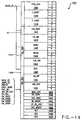
- FIG. 12A block diagram of the IDU is shown in Fig. 12. Aligned instructions from the IAU arrive at the IDU on a bus 1201 which is 32 bits wide ([31:0] or 4 bytes). The aligned instructions are received by an Instruction Decoder 1202. The IDU 1202 only looks at the first four bytes of an aligned instruction in order to perform the CISC to RISC transformation.
- the Instruction Decoder 1202operates in one clock phase (a half cycle).
- the aligned instructiongoes through the decoder and the decoded information that exits is MUXed and fed into a half cycle delay latch 1204 via a bus 1203.
- the decoded informationtherefore experiences the equivalent to a one phase pipeline delay.
- the decoded informationis sent via a bus 1205 to a MUX 1206 to determine the actual register codes used.
- the decoded informationis arranged in the nano- instruction format.
- the nano-instructionis then latched.
- Two complete nano-instruction bucketsare latched per cycle.
- the latching of two nano- instruction bucketsis shown diagrammatically by 1st IR and 2nd IR buckets 1208 and 1210, respectively.
- the IDUattempts to assemble buckets 1208 and 1210 into a single bucket 1212. This assembly is performed by a set of control gates 1214.
- the IDUfirst looks at the TYPE of each nano-instruction, and determines if the TYPEs are such that they can be combined. Note that either LoaD (LD) operation of the two latched instructions can be placed in a LD location 1216 of the single bucket 1212; either STore (ST) operation of the latched instructions can be placed in a ST location 1218 of the single bucket; either A0 operation can be placed in an A0 location 1220; and any A0 or A1 operation can be placed in an A1 location 1222.
- LDLoaD
- STSTore
- the IDUtreats the instructions as a whole. If the IDU cannot pack the two instructions into one bucket, it will leave one complete instruction behind. For example, if the 1st IR latch has only an A0 operation, and the 2nd IR latch includes all four operations, the IFU will not take the A1 from the 2nd IR latch and merge it with the A0 operation. The A0 operation will be sent by itself and the 2nd IR latch's set of operations will be transferred to the 1st IR latch and sent on the next phase, during which time the 2nd IR latch is reloaded. In other words, the operations stored in the 1st IR latch will always be sent, and the operations stored in the 2nd IR latch will be combined with the 1st IR latch operations if possible. The previous pipeline stages of the IDU and IAU must wait in the event that the 1st and 2nd IRs cannot be combined. The following situations permit the IDU to combine the 1st and 2nd IR latch operations:
- Combination logiccan readily be designed by those skilled in the art to generate the necessary control signals for the control gates to merge the content of the 1st and 2nd IR latches, based on the functionality discussed above and basic logic design practice.
- Emulation modeis entered when the IDU identifies an instruction belonging to the subset of instructions requiring emulation.
- An EMULation MODE control signal(EMUL_MODE) is sent to the decoders of the IDU once emulation mode is entered.
- Direct decoding of the CISC instructionstops, and the microcode routine corresponding to the identified instruction is sent to the IDU for decoding.
- the IDU decodersreturn to basic mode for decoding further CISC instructions when the microcode routine is finished emulation of the subset instruction. Fundamentally, basic CISC instructions and microcode instructions are handled in the same way by the IDU. Only the interpretation of the opcode changes.
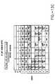
- Karnaugh maps of the default (basic) mode for both 1 and 2 byte opcode instructionsare shown at Fig's. 13A-13C.
- the numbers along the left hand side and the top of the Karnaugh mapsrepresent the opcode bits.
- a one-byte opcode coded as hex 0Fcorresponds to the first row and 11th column, which is the "2 byte escape" instruction.
- the Instruction Decoder 1202includes a plurality of decoders that are used to decode the CISC instructions and microcode routines.
- a TYPE GENerator (TYPE_GEN) decoder 1402receives the first full aligned instructions on the ALIGN_IR bus, and decodes instructions one at a time to identify the TYPE field of the instruction.
- the identified TYPE fieldcorresponds to the nano-instruction operations discussed above in connection with the IDU.
- the TYPEis signified by a 4 bit field representing each operation in a bucket (Load, ALU0, Store and ALU1).
- the TYPE_GEN decoder 1402specifies which of those four operations are needed to execute the instruction. Depending on the instruction received, any number from 1-4 of the operations may be required to satisfy the CISC instruction.
- an add operationwhich sums the contents in one register with the contents in another register, requires only one ALU nano-instruction operation.
- an instruction which requires the addition of the contents of a register with a memory locationwould require a Load, an ALU operation and then a Store operation, thus totalling three nano-instruction operations. (The data must be read from memory, added to the register, and then stored back in memory). More complicated CISC instructions may require all four nano-instructions.
- the TYPE_GEN decoder 1402comprises three TYPE decoders.
- a first decoder TYPE1assumes that the instruction has a one-byte opcode followed by the ModR/M byte, and computes the TYPE based on that assumption.
- a second decoder TYPE2assumes that the instruction has a two-byte opcode. The first byte being the ESCAPE byte, followed by the second byte which is the opcode and the third byte which is the ModR/M byte.
- a third decoder TYPEFassumes that the instruction is a floating point instruction, and decodes the instruction based on that assumption.
- the TYPE_GEN decoderhas three 4 bit wide TYPE instruction output buses (TYPE1, TYPE2, and TYPEF). Each bit corresponds to one of the 4 nano-instruction operations in a bucket.
- the specific TYPE fieldspecifies which nano-instruction operations are necessary to carry out the CISC instruction. For example, if all 4 bits are logic HIGH, the CISC instruction requires a Load, a Store and two ALU operations.
- Fig. 14that include sections labeled 1, 2 and F decode assuming a 1 byte opcode, a 2 byte opcode and a floating point instruction, respectively.
- the invalid resultsare merely not selected.
- a multiplexerselects the output of the correct decoder.
- the two ALU operationseach have an opcode field which is 11 bits long.
- the 11 bitscomprise the 8 bits of the opcode and three opcode extension bits from the adjacent ModR/M byte.
- the opcode bitsare directly copied to the nano-instruction operations.
- Some CISC instructionsmay require opcode substitution; here the IDU unit does not merely filter the CISC opcode to the instruction execution unit (IEU). This will become evident to those skilled in the art, because the type and number of functional units in the IEU will dictate whether or not opcode replacement is required within the IDU for specific CISC instructions.
- the IDUtherefore includes a Functional zero UNIT (F_0UNIT) decoder 1410, which comprises decoders F_0UNIT1 F_0UNIT2 and F_0UNITF.
- the outputs of the decodersare multi-byte fields that indicate which functional unit is necessary for processing the A0 ALU operation.
- the functional unit decoding for the A1 ALU operationis identical, but is handled by a separate decoder F_1UNIT 1412.
- CST_GENConSTant GENerator
- TempCountAn additional two bit control signal, TempCount (TC), is input to the CST_GEN decoder.
- the TC control signalis a two bit counter representing 4 temporary registers which may be cycled through for use as dummy registers by the IEU.
- the temporary (or dummy) registersrepresent another value of register that can be passed on by the CST_GEN decoder, in addition to the implied registers.
- the constant generator decoderpasses on 4 constant fields because there are 2 ALU operations having 2 registers per operation.
- Each constant register busis 20 bits wide, with each constant being a total of 5 bits, thereby permitting selection of one of the 32 registers in the IEU.
- the SEL_GEN decoderincludes a FlaG Need Modify (FG_NM) decoder 1418.
- the FG_NM decoderdecodes for a one-byte opcode, a 2 byte opcode and a floating point instruction. In the i486 instruction set, for example, there are a total of 6 flags. These flags have to be valid before execution of some instructions begin, while the flags may be modified by some instructions.
- the FG_NM decoderoutputs two signals per flag, one bit indicates whether the flag is needed for execution of this instruction and the other indicates whether or not this instruction actually modifies the flag.
- Register INValiDation information concerning the ALU0 and ALU1 operationsare decoded by an INVD1 and an INVD2 decoder, shown at 1420 and 1422 respectively.
- the INVD1 and INVD2 decodersare also part of the SEL_GEN decoder 1416.
- INVD1 and INVD2generate control signals for the IEU. These signals indicate whether the ALU registers should be used or not.
- Three possible register indicescan be specified by each ALU operation. One can be used as a source and/or destination register, and the remaining two are limited to specifying source registers.
- a 4 bit fieldis uses to specify which register(s) are required by the operation.
- the SEL_GEN decoder 1416further includes a FLD_CNT decoder 1424 that indicates which of the register fields is required for the CISC instruction.
- the FLD_CNT decoderspecifies which of the 2 fields is the source register and which is the destination register.
- a Nano-InstRuction GENerator (NIR_GEN) decoderis shown generally as block 1426.
- the data size (DATA_SZ) and address size (ADDR_SZ) input control signalscorrespond to the default that the system is operating in. In order to decode the final address and operand size, the default mode must be known and the presence of any prefixes (discussed above in conjunction with the IAU) must be known.
- the EMUL_MODE control signalis also input to the NIR_GEN decoder, but it is also used by the other decoders.
- the ESCape DETect (ESC_DET) input control signalis fed to the NIR_GEN decoder to indicate whether the instruction has a 2 byte opcode.
- a SELect OPcode EXTension (SEL_OP_EXT) input control signalis used to generate loading of the mailbox registers when an emulation instruction is detected.
- a Floating Point REGister (FP_REG) input control signalpasses the translated floating point register index to the IDU.
- the floating point format of the i486for example, has eight registers for floating point numbers, but the registers are accessed like a stack. Accessing these registers is accomplished by using a stack accessing scheme: register0 being the top of the stack, register1 being the next top register, etc .
- This register stackis emulated by using eight linear registers with fixed indices.
- a translation block(not shown), translates the stack relative register index into the register index for the linear registers in a known manner. This permits the IDU to keep track of which register is on the top of the stack.
- the IDUWhen the system branches to emulation mode, the IDU saves information about the instruction being emulated.
- the IDUsaves the Data SIZE (EM_DSIZE) and Address SIZE (EM_ASIZE) of the instruction, as well as the Register index of the DESTination (EM_RDEST), the source (EM_RDEST2) and the Base InDeX information (EM_BSIDX).
- EM_DSIZEData SIZE
- EM_ASIZEAddress SIZE
- EM_RDESTRegister index of the DESTination
- EM_RDEST2the source
- EM_BSIDXBase InDeX
- This saved informationis used by the microcode routine to properly emulate the instruction. Take for example the emulation of an add instruction.
- the microcode routinemay check EM_ASIZE to determine the address size of the add instruction so that it knows what address size to emulate.
- the NIR_GEN decoder 1426includes a SIZE decoder 1428.
- the fields generated by the SIZE decoderi.e., SIZE1, SIZE2 and SIZEF
- SIZE1, SIZE2 and SIZEFindicate the address size, operand size and immediate data size of the instruction.
- An address size of 16 or 32 bits, an operand size of 8, 16 or 32 bits and an immediate data field size of 8, 16 or 32 bitsare extracted for each instruction.
- L_INFLoaD INFormation
- the LD_INF decoderdecodes information corresponding to the Load and Store operations.
- the Load informationis used for effective address calculations.
- the Load information fields(LD_INF1, LD_INF2 and LD_INFF) can be used to specify which addressing mode is being used by the CISC instruction, since CISC instruction sets usually support many different addressing modes.
- the i486 basic addressing modeincludes a segment field and an offset which are added together to determine the address.
- An index registercan be specified, as well as a scale for the index register (e.g., if the index registers are elements in an array), the elements can be specified as 1, 2, 4 or 8-bytes in length, thus the index register can be scaled by 1, 2, 4 or 8 before it is added to determine the address.
- the base and indexare also specified by the LD_INF fields.
- a Nano-InstRuction OPCode (NIR_OPC) decoder 1432transfers opcode for the A1 operation (packet1).
- the decoded fields (NIR_OPC1, NIR_OPC2 and NIR_OPCF)comprise the first instruction byte (8 bits), plus three extension bits from the second byte.
- MISC_OPCMIScellaneous OPCode
- the opcode for the A0 operation of packet0is specified by an OP_CODE decoder 1436.
- the A0 opcodeis usually copied directly from the i486 input opcode, but for some instructions the opcode is replaced by an alternate opcode.
- the functionality of the signals generated by the NIR_GEN decoderare specific to the CISC instruction set being decoded, and thus should become evident to those skilled in the art upon review of the CISC instruction set and the nano-instruction format of the present invention.
- An EXT_CODE decoder 1440extracts the 3 bit opcode extension from the ModR/M byte.
- a IN_ORDER decoder 1442decodes the instruction to determine whether the instruction must be executed "in order". This instructs the IEU not to do anything with this instruction until all the previous instructions have been executed. Once the execution of the instruction is completed, execution of subsequent instructions is started.
- a Control flow Jump Size decoder 1444indicates the displacement size for jumps that specify an address. This field, labeled CF_JV_SIZE, specifies the size of the address for the jump. This is specific to the type of addressing scheme employed by the CISC instruction set.
- a 1 bit decoder labeled DEC_MDEST 1446indicates whether or not the destination of the instruction is a memory address.
- the Instruction Decoderincludes three Register Code decoders 1438 to select the register codes (indices).
- the i486 instruction formatencodes the index of the register fields in various places within the instruction. The indices of these fields are extracted by the RC decoder.
- the ModR/M bytealso has two register indices, which are used as the destination/source as specified by the opcode itself.
- the Register Code decoder 1438generates three RC fields RC1, RC2 and RC3.
- RC1, RC2 and RC3are assigned as follows:
- Fig. 15shows a representative block and logic gate diagram for the CST_GEN, NIR_GEN and SEL_GEN decoders (1414, 1438 and 1424 respectively). It should be understood that this Fig. 15 is an example of how the 1 byte opcode, 2 byte opcode and floating point decoded results are selected, delayed, and combined to generate source and destination register indices for nano-instruction operations A0 and A1, and the destination register index for the Load instruction.
- the methodology of the selection, delay and multiplexingapplies to all of the signals generated by the INSTRUCTION DECODER 1202, with the exception of those signals which do not generate separate 1 byte opcode, 2 byte opcode and floating point results.
- results generated by this exampleare application specific, in other words, they apply to decoding of i486 instructions into the nano-instruction format of the present invention.
- the principles discussed throughout these examples, however,are generally applicable to any CISC to RISC instruction alignment and decoding.
- the CST_GEN decoder 1414generates three outputs, CST1, CST2 and CSTF, each of which comprise four constant 5 bit register fields (20 bits total).
- the SEL_GENgenerates register field control signals (FLD1, FLD2, and FLD3 for the selection of the multiplexers in a further section MUX 1512.
- the selection of the CST1, CST2 or CSTF results and the FLD1, FLD2, and FLDF resultsis shown generally at the multiplexer block 1502.
- a 3 bit MUX select line 1504is used to select the results depending on whether the instruction has a 1 byte opcode, 2 byte opcode, or is a floating point instruction.
- a ⁇ cycle pipeline delay latch 1504is used to delay the results selected by the multiplexer 1502, and the three register control fields RC1, RC2, and RC3. Each input to the ⁇ pipeline delay 1504 is sent to a pair of oppositely clocked latches 1508. The contents of' the latches are selected by a multiplexers 1510. This arrangement is similar to the ⁇ cycle delay 316 discussed above in connection to the IAU.
- a further multiplexing stageis shown in block 1512.
- the constant register fields selected by the multiplexer 1502are input to the multiplexer 1512 as four separate fields labeled regc1 through regc4, respectively, as shown generally at 1514.
- Also shown as inputs to the block 1512are the EXTRACT REGISTER fields RC1, RC2, and RC3 from the opcode and ModR/M bytes.
- the regc fields and RC fieldsare combined by logic in the block 1512 under control of an FLD control signal 1520 to generate the source and destination register indexes a0_rd and a0_rs for operation A0, which are shown generally at 1516, as well as the source and destination register indexes a1_rd and a1_rs for operation A1, which are shown generally at 1518.
- An index 1d_rdwhich is the destination register index for the Load instruction, is also selected in the block 1512.
- FIG. 16AA block diagram of a Decode FIFO (DFIFO) in conjunction with the present invention is shown in Fig. 16A.
- the DFIFOholds four complete buckets, each of which contains four nano-instructions, two immediate data fields, and one displacement field. Each bucket corresponds to one level of pipeline register in the DFIFO. These buckets are generated in the IDU and pushed to the DFIFO during each cycle that the IEU requests a new bucket.
- the nano-instructions in a bucketare divided into two groups, called packet0 and packet1.
- Packet0can consist of a Load, ALU, and/or Store operation, which corresponds to one, two, or three nano-instruction.
- Packet 1can only be an ALU operation, corresponding to one nano-instruction.
- a bucketcan only contain two ALU operations, and only one of them can reference memory. If subsequent instructions both require memory operands, they must be placed in separate buckets.
- Fig. 16Bthere is only a fair amount of general information associated with each packet and with the bucket as a whole.
- This informationis stored in a general information FIFO.
- the four nano-instructions in a bucketare executed in order, from NIR0 to NIR3.
- One of the bucket general information bitscan be set to indicate that NIR3 should be executed before NIR0-NIR2. This feature makes it much easier to combine subsequent instructions into a single bucket, because their order no longer affects their ability to fit the bucket requirements.
- Fig. 16Cshows an immediate data and displacement FIFO for buckets0-4.
- IMM0represents the immediate data corresponding to packet0
- IMM1represents the immediate data corresponding to packet1.
- DISPrepresents the displacement corresponding to packet0.
- Packet1does not use DISP information because the DISP fields are only used as a part of address calculation.
Landscapes
- Engineering & Computer Science (AREA)
- Software Systems (AREA)
- Theoretical Computer Science (AREA)
- Physics & Mathematics (AREA)
- General Engineering & Computer Science (AREA)
- General Physics & Mathematics (AREA)
- Advance Control (AREA)
- Executing Machine-Instructions (AREA)
Abstract
Description
- Opcode, eight bits plus 3 optional extension bits. For 2 byteopcodes, the first byte is always 0F hex, so the second byte issent as the opcode.
- ModR/M byte, SIB byte, and Displacement and Immediatedata; and
- Information concerning the number and type of prefixes.
- Decode one CISC instruction per half cycle;
- Decode the 1st CISC instruction in a first phase;
- Hold as valid the decoded results of the 1st CISC instruction throughthe second phase;
- Decode the 2nd CISC instruction in the second phase;
- Combine the outputs of two instructions, if possible in the third phase;and
- Output one bucket comprising four nano-instructions per cycle.
- RC1: bits [4:0] of
byte 3; - RC2: bits [1:0] of
byte 2 and bits [7:5] ofbyte 3; and - RC3: bits [6:1] of
byte 2.
Claims (5)
- A superscalar microprocessor for executing instructions obtained from an instruction store,said microprocessor comprising:a fetch circuit to fetch a plurality of CISC instructions from said instruction store, the pluralityof CISC instructions being in program order;a decoder to decode said CISC instructions into RISC instructions having a predeterminedsequence; anda dispatch circuit to concurrently dispatch more than one of said plurality of RISC instructionsdecoded by said decoder; andan execution unit comprisingwherein said register file communicates with said plurality of functional units via a pluralityof data routing paths for concurrently providing data to more than one of said functional units andthereby enabling concurrent execution of more than one of said plurality instructions by said pluralityof functional units,a plurality of functional units, each of said plurality of functional unitsexecuting one of said plurality of RISC instructions dispatched by said dispatch circuit out ofthe predetermined sequence, anda register file for storing data from said plurality of functional units in aplurality of registers, and
wherein first and second CISC instructions are decoded by said decoder into one or more firstRISC instructions and one or more second RISC instructions, respectively, per clock cycle,
wherein said execution unit further comprises first and second registers each comprising RISCinstruction storage locations, wherein said first RISC instructions and said second RISC instructionsare stored in said first register. - A superscalar microprocessor according to Claim 1, wherein each one of said first andsecond registers comprises four RISC instruction storage locations.
- A superscalar microprocessor, comprising:means for storing data in a plurality of registers identifiable by register references, saidplurality of registers including a predetermined register and a temporary register;means for fetching CISC instructions to be executed, wherein at least one said CISCinstructions includes a register reference;means for decoding said CISC instructions into RISC instructions having a predeterminedsequence; and
executing means for executing at least two of said RISC instructions concurrently and out of saidpredetermined sequence, said executing means including means for selecting said temporary registerwhere the execution of said instruction provides said register reference to select said predeterminedregister for the storage of data,
wherein first and second CISC instructions are decoded by said decoding means into one ormore first RISC instructions and one or more second RISC instructions, respectively, per clock cycle,
wherein said executing means comprises first and second registers each comprising RISCinstruction storage locations, wherein said first RISC instructions and said second RISC instructionsare stored in said first register. - A superscalar microprocessor according to Claim 2, wherein each one of said first andsecond registers comprises four RISC instruction storage locations.
- A superscalar microprocessor, comprising:memory to store data in a plurality of registers identifiable by register references, saidplurality of registers including a predetermined register and a temporary register;fetch unit to fetch CISC instructions to be executed, wherein at least oneof said CISC instructions includes a register reference;decoder to decode said CISC instructions into RISC instructions having a predeterminedsequence; andexecution unit to execute at least two of said RISC instructions concurrently andout of said predetermined sequence, said execution unit includes a selector to select saidtemporary register where the execution of said instruction provides said registerreference to select said predetermined register for the storage of data,
wherein first and second CISC instructions are decoded by saiddecoder into one or more first RISC instructions and one or more second RISCinstructions, respectively, per clock cycle, wherein said execution unit comprises first and secondregisters each comprising RISC instruction storage locations, wherein said first RISCinstructions and said second RISC instructions are stored in said first register.
Applications Claiming Priority (3)
| Application Number | Priority Date | Filing Date | Title |
|---|---|---|---|
| US857599 | 1992-03-31 | ||
| US07/857,599US5438668A (en) | 1992-03-31 | 1992-03-31 | System and method for extraction, alignment and decoding of CISC instructions into a nano-instruction bucket for execution by a RISC computer |
| EP93906870AEP0636257B1 (en) | 1992-03-31 | 1993-03-30 | Cisc to risc instruction translation alignment and decoding |
Related Parent Applications (1)
| Application Number | Title | Priority Date | Filing Date |
|---|---|---|---|
| EP93906870ADivisionEP0636257B1 (en) | 1992-03-31 | 1993-03-30 | Cisc to risc instruction translation alignment and decoding |
Publications (3)
| Publication Number | Publication Date |
|---|---|
| EP1028370A2true EP1028370A2 (en) | 2000-08-16 |
| EP1028370A3 EP1028370A3 (en) | 2002-02-20 |
| EP1028370B1 EP1028370B1 (en) | 2004-09-15 |
Family
ID=25326342
Family Applications (2)
| Application Number | Title | Priority Date | Filing Date |
|---|---|---|---|
| EP93906870AExpired - LifetimeEP0636257B1 (en) | 1992-03-31 | 1993-03-30 | Cisc to risc instruction translation alignment and decoding |
| EP00108579AExpired - LifetimeEP1028370B1 (en) | 1992-03-31 | 1993-03-30 | System and method for translating a stream of non-native instructions for processing on a host processor |
Family Applications Before (1)
| Application Number | Title | Priority Date | Filing Date |
|---|---|---|---|
| EP93906870AExpired - LifetimeEP0636257B1 (en) | 1992-03-31 | 1993-03-30 | Cisc to risc instruction translation alignment and decoding |
Country Status (6)
| Country | Link |
|---|---|
| US (8) | US5438668A (en) |
| EP (2) | EP0636257B1 (en) |
| JP (3) | JP3547052B2 (en) |
| KR (2) | KR100343530B1 (en) |
| DE (2) | DE69329644T2 (en) |
| WO (1) | WO1993020507A2 (en) |
Cited By (2)
| Publication number | Priority date | Publication date | Assignee | Title |
|---|---|---|---|---|
| EP1447742A1 (en)* | 2003-02-11 | 2004-08-18 | STMicroelectronics S.r.l. | Method and apparatus for translating instructions of an ARM-type processor into instructions for a LX-type processor |
| EP1387252A3 (en)* | 2002-07-31 | 2007-12-26 | Texas Instruments Incorporated | Instruction prefix to indicate system commands |
Families Citing this family (244)
| Publication number | Priority date | Publication date | Assignee | Title |
|---|---|---|---|---|
| US5768575A (en)* | 1989-02-24 | 1998-06-16 | Advanced Micro Devices, Inc. | Semi-Autonomous RISC pipelines for overlapped execution of RISC-like instructions within the multiple superscalar execution units of a processor having distributed pipeline control for sepculative and out-of-order execution of complex instructions |
| US5226126A (en)* | 1989-02-24 | 1993-07-06 | Nexgen Microsystems | Processor having plurality of functional units for orderly retiring outstanding operations based upon its associated tags |
| US5781753A (en) | 1989-02-24 | 1998-07-14 | Advanced Micro Devices, Inc. | Semi-autonomous RISC pipelines for overlapped execution of RISC-like instructions within the multiple superscalar execution units of a processor having distributed pipeline control for speculative and out-of-order execution of complex instructions |
| US5438668A (en)* | 1992-03-31 | 1995-08-01 | Seiko Epson Corporation | System and method for extraction, alignment and decoding of CISC instructions into a nano-instruction bucket for execution by a RISC computer |
| US5628021A (en)* | 1992-12-31 | 1997-05-06 | Seiko Epson Corporation | System and method for assigning tags to control instruction processing in a superscalar processor |
| US5463748A (en)* | 1993-06-30 | 1995-10-31 | Intel Corporation | Instruction buffer for aligning instruction sets using boundary detection |
| JP3248992B2 (en)* | 1993-07-13 | 2002-01-21 | 富士通株式会社 | Multiprocessor |
| DE69427265T2 (en)* | 1993-10-29 | 2002-05-02 | Advanced Micro Devices, Inc. | Superskalarbefehlsdekoder |
| EP0651321B1 (en)* | 1993-10-29 | 2001-11-14 | Advanced Micro Devices, Inc. | Superscalar microprocessors |
| EP0651324B1 (en)* | 1993-10-29 | 2006-03-22 | Advanced Micro Devices, Inc. | Speculative instruction queue for variable byte length instructions |
| US5689672A (en)* | 1993-10-29 | 1997-11-18 | Advanced Micro Devices, Inc. | Pre-decoded instruction cache and method therefor particularly suitable for variable byte-length instructions |
| US5630082A (en)* | 1993-10-29 | 1997-05-13 | Advanced Micro Devices, Inc. | Apparatus and method for instruction queue scanning |
| US5903772A (en)* | 1993-10-29 | 1999-05-11 | Advanced Micro Devices, Inc. | Plural operand buses of intermediate widths coupling to narrower width integer and wider width floating point superscalar processing core |
| JPH07239780A (en)* | 1994-01-06 | 1995-09-12 | Motohiro Kurisu | One-clock variable length instruction execution process type instruction read computer |
| US5884057A (en)* | 1994-01-11 | 1999-03-16 | Exponential Technology, Inc. | Temporal re-alignment of a floating point pipeline to an integer pipeline for emulation of a load-operate architecture on a load/store processor |
| US5600806A (en)* | 1994-03-01 | 1997-02-04 | Intel Corporation | Method and apparatus for aligning an instruction boundary in variable length macroinstructions with an instruction buffer |
| JP3212213B2 (en)* | 1994-03-16 | 2001-09-25 | 株式会社日立製作所 | Data processing device |
| US5574927A (en)* | 1994-03-25 | 1996-11-12 | International Meta Systems, Inc. | RISC architecture computer configured for emulation of the instruction set of a target computer |
| EP0679990B1 (en)* | 1994-04-28 | 2000-03-01 | Hewlett-Packard Company | A computer apparatus having a means to force sequential instruction execution |
| US5559975A (en)* | 1994-06-01 | 1996-09-24 | Advanced Micro Devices, Inc. | Program counter update mechanism |
| JP2982618B2 (en)* | 1994-06-28 | 1999-11-29 | 日本電気株式会社 | Memory selection circuit |
| US5598546A (en)* | 1994-08-31 | 1997-01-28 | Exponential Technology, Inc. | Dual-architecture super-scalar pipeline |
| US5619663A (en)* | 1994-09-16 | 1997-04-08 | Philips Electronics North America Corp. | Computer instruction prefetch system |
| US6496922B1 (en)* | 1994-10-31 | 2002-12-17 | Sun Microsystems, Inc. | Method and apparatus for multiplatform stateless instruction set architecture (ISA) using ISA tags on-the-fly instruction translation |
| US5640526A (en)* | 1994-12-21 | 1997-06-17 | International Business Machines Corporation | Superscaler instruction pipeline having boundary indentification logic for variable length instructions |
| US6006324A (en) | 1995-01-25 | 1999-12-21 | Advanced Micro Devices, Inc. | High performance superscalar alignment unit |
| US5832249A (en)* | 1995-01-25 | 1998-11-03 | Advanced Micro Devices, Inc. | High performance superscalar alignment unit |
| US5737550A (en)* | 1995-03-28 | 1998-04-07 | Advanced Micro Devices, Inc. | Cache memory to processor bus interface and method thereof |
| US5751982A (en)* | 1995-03-31 | 1998-05-12 | Apple Computer, Inc. | Software emulation system with dynamic translation of emulated instructions for increased processing speed |
| US5991869A (en)* | 1995-04-12 | 1999-11-23 | Advanced Micro Devices, Inc. | Superscalar microprocessor including a high speed instruction alignment unit |
| US5822558A (en)* | 1995-04-12 | 1998-10-13 | Advanced Micro Devices, Inc. | Method and apparatus for predecoding variable byte-length instructions within a superscalar microprocessor |
| US5758114A (en)* | 1995-04-12 | 1998-05-26 | Advanced Micro Devices, Inc. | High speed instruction alignment unit for aligning variable byte-length instructions according to predecode information in a superscalar microprocessor |
| US5815736A (en)* | 1995-05-26 | 1998-09-29 | National Semiconductor Corporation | Area and time efficient extraction circuit |
| US6237074B1 (en)* | 1995-05-26 | 2001-05-22 | National Semiconductor Corp. | Tagged prefetch and instruction decoder for variable length instruction set and method of operation |
| US5680578A (en)* | 1995-06-07 | 1997-10-21 | Advanced Micro Devices, Inc. | Microprocessor using an instruction field to specify expanded functionality and a computer system employing same |
| US5822778A (en)* | 1995-06-07 | 1998-10-13 | Advanced Micro Devices, Inc. | Microprocessor and method of using a segment override prefix instruction field to expand the register file |
| US5875315A (en)* | 1995-06-07 | 1999-02-23 | Advanced Micro Devices, Inc. | Parallel and scalable instruction scanning unit |
| US5768574A (en)* | 1995-06-07 | 1998-06-16 | Advanced Micro Devices, Inc. | Microprocessor using an instruction field to expand the condition flags and a computer system employing the microprocessor |
| JP3451595B2 (en)* | 1995-06-07 | 2003-09-29 | インターナショナル・ビジネス・マシーンズ・コーポレーション | Microprocessor with architectural mode control capable of supporting extension to two distinct instruction set architectures |
| US5867701A (en)* | 1995-06-12 | 1999-02-02 | Intel Corporation | System for inserting a supplemental micro-operation flow into a macroinstruction-generated micro-operation flow |
| US5678032A (en)* | 1995-09-06 | 1997-10-14 | Bull Hn Information Systems Inc. | Method of optimizing the execution of program instuctions by an emulator using a plurality of execution units |
| DE69638241D1 (en)* | 1995-08-01 | 2010-09-30 | Bull Hn Information Syst | PROCEDURE FOR THE EMULATION OF PROGRAM COMMANDS |
| US5781789A (en)* | 1995-08-31 | 1998-07-14 | Advanced Micro Devices, Inc. | Superscaler microprocessor employing a parallel mask decoder |
| US5809273A (en)* | 1996-01-26 | 1998-09-15 | Advanced Micro Devices, Inc. | Instruction predecode and multiple instruction decode |
| US5794063A (en)* | 1996-01-26 | 1998-08-11 | Advanced Micro Devices, Inc. | Instruction decoder including emulation using indirect specifiers |
| US5926642A (en) | 1995-10-06 | 1999-07-20 | Advanced Micro Devices, Inc. | RISC86 instruction set |
| US6093213A (en)* | 1995-10-06 | 2000-07-25 | Advanced Micro Devices, Inc. | Flexible implementation of a system management mode (SMM) in a processor |
| US5819056A (en)* | 1995-10-06 | 1998-10-06 | Advanced Micro Devices, Inc. | Instruction buffer organization method and system |
| US5920713A (en)* | 1995-10-06 | 1999-07-06 | Advanced Micro Devices, Inc. | Instruction decoder including two-way emulation code branching |
| DE69629484D1 (en)* | 1995-10-06 | 2003-09-18 | Advanced Micro Devices Inc | COMMAND PRECODING AND DECODING MULTIPLE COMMANDS |
| US5872947A (en)* | 1995-10-24 | 1999-02-16 | Advanced Micro Devices, Inc. | Instruction classification circuit configured to classify instructions into a plurality of instruction types prior to decoding said instructions |
| US5768553A (en)* | 1995-10-30 | 1998-06-16 | Advanced Micro Devices, Inc. | Microprocessor using an instruction field to define DSP instructions |
| US5796974A (en)* | 1995-11-07 | 1998-08-18 | Advanced Micro Devices, Inc. | Microcode patching apparatus and method |
| US5790825A (en)* | 1995-11-08 | 1998-08-04 | Apple Computer, Inc. | Method for emulating guest instructions on a host computer through dynamic recompilation of host instructions |
| US5809272A (en)* | 1995-11-29 | 1998-09-15 | Exponential Technology Inc. | Early instruction-length pre-decode of variable-length instructions in a superscalar processor |
| US5778246A (en)* | 1995-12-27 | 1998-07-07 | Intel Corporation | Method and apparatus for efficient propagation of attribute bits in an instruction decode pipeline |
| US5740392A (en)* | 1995-12-27 | 1998-04-14 | Intel Corporation | Method and apparatus for fast decoding of 00H and OFH mapped instructions |
| US5710914A (en)* | 1995-12-29 | 1998-01-20 | Atmel Corporation | Digital signal processing method and system implementing pipelined read and write operations |
| US5819080A (en)* | 1996-01-02 | 1998-10-06 | Advanced Micro Devices, Inc. | Microprocessor using an instruction field to specify condition flags for use with branch instructions and a computer system employing the microprocessor |
| US5826089A (en)* | 1996-01-04 | 1998-10-20 | Advanced Micro Devices, Inc. | Instruction translation unit configured to translate from a first instruction set to a second instruction set |
| JP3634379B2 (en)* | 1996-01-24 | 2005-03-30 | サン・マイクロシステムズ・インコーポレイテッド | Method and apparatus for stack caching |
| KR100618756B1 (en)* | 1996-01-24 | 2007-05-04 | 선 마이크로시스템즈 인코퍼레이티드 | Processors and computer systems that execute instruction sets received from network or local memory |
| US6105124A (en)* | 1996-01-26 | 2000-08-15 | Intel Corporation | Method and apparatus for merging binary translated basic blocks of instructions |
| US5790821A (en) | 1996-03-08 | 1998-08-04 | Advanced Micro Devices, Inc. | Control bit vector storage for storing control vectors corresponding to instruction operations in a microprocessor |
| US5822560A (en)* | 1996-05-23 | 1998-10-13 | Advanced Micro Devices, Inc. | Apparatus for efficient instruction execution via variable issue and variable control vectors per issue |
| US5867681A (en)* | 1996-05-23 | 1999-02-02 | Lsi Logic Corporation | Microprocessor having register dependent immediate decompression |
| US5905893A (en)* | 1996-06-10 | 1999-05-18 | Lsi Logic Corporation | Microprocessor adapted for executing both a non-compressed fixed length instruction set and a compressed variable length instruction set |
| US5896519A (en)* | 1996-06-10 | 1999-04-20 | Lsi Logic Corporation | Apparatus for detecting instructions from a variable-length compressed instruction set having extended and non-extended instructions |
| JP2000515275A (en)* | 1996-07-16 | 2000-11-14 | アドバンスト・マイクロ・ディバイシズ・インコーポレイテッド | Superscalar microprocessor including high-speed instruction alignment unit |
| US6049863A (en)* | 1996-07-24 | 2000-04-11 | Advanced Micro Devices, Inc. | Predecoding technique for indicating locations of opcode bytes in variable byte-length instructions within a superscalar microprocessor |
| US5867680A (en)* | 1996-07-24 | 1999-02-02 | Advanced Micro Devices, Inc. | Microprocessor configured to simultaneously dispatch microcode and directly-decoded instructions |
| US5958061A (en)* | 1996-07-24 | 1999-09-28 | Transmeta Corporation | Host microprocessor with apparatus for temporarily holding target processor state |
| US6199152B1 (en) | 1996-08-22 | 2001-03-06 | Transmeta Corporation | Translated memory protection apparatus for an advanced microprocessor |
| US5926832A (en)* | 1996-09-26 | 1999-07-20 | Transmeta Corporation | Method and apparatus for aliasing memory data in an advanced microprocessor |
| US5890009A (en)* | 1996-12-12 | 1999-03-30 | International Business Machines Corporation | VLIW architecture and method for expanding a parcel |
| US5870576A (en)* | 1996-12-16 | 1999-02-09 | Hewlett-Packard Company | Method and apparatus for storing and expanding variable-length program instructions upon detection of a miss condition within an instruction cache containing pointers to compressed instructions for wide instruction word processor architectures |
| US5918031A (en)* | 1996-12-18 | 1999-06-29 | Intel Corporation | Computer utilizing special micro-operations for encoding of multiple variant code flows |
| US5923862A (en)* | 1997-01-28 | 1999-07-13 | Samsung Electronics Co., Ltd. | Processor that decodes a multi-cycle instruction into single-cycle micro-instructions and schedules execution of the micro-instructions |
| US5909567A (en)* | 1997-02-28 | 1999-06-01 | Advanced Micro Devices, Inc. | Apparatus and method for native mode processing in a RISC-based CISC processor |
| US5852727A (en)* | 1997-03-10 | 1998-12-22 | Advanced Micro Devices, Inc. | Instruction scanning unit for locating instructions via parallel scanning of start and end byte information |
| US5875336A (en)* | 1997-03-31 | 1999-02-23 | International Business Machines Corporation | Method and system for translating a non-native bytecode to a set of codes native to a processor within a computer system |
| US6047368A (en)* | 1997-03-31 | 2000-04-04 | Sun Microsystems, Inc. | Processor architecture including grouping circuit |
| US5940602A (en)* | 1997-06-11 | 1999-08-17 | Advanced Micro Devices, Inc. | Method and apparatus for predecoding variable byte length instructions for scanning of a number of RISC operations |
| US6009511A (en)* | 1997-06-11 | 1999-12-28 | Advanced Micro Devices, Inc. | Apparatus and method for tagging floating point operands and results for rapid detection of special floating point numbers |
| US5933626A (en)* | 1997-06-12 | 1999-08-03 | Advanced Micro Devices, Inc. | Apparatus and method for tracing microprocessor instructions |
| US5930491A (en)* | 1997-06-18 | 1999-07-27 | International Business Machines Corporation | Identification of related instructions resulting from external to internal translation by use of common ID field for each group |
| US5978901A (en)* | 1997-08-21 | 1999-11-02 | Advanced Micro Devices, Inc. | Floating point and multimedia unit with data type reclassification capability |
| US6230259B1 (en) | 1997-10-31 | 2001-05-08 | Advanced Micro Devices, Inc. | Transparent extended state save |
| US6438679B1 (en) | 1997-11-03 | 2002-08-20 | Brecis Communications | Multiple ISA support by a processor using primitive operations |
| US5923894A (en) | 1997-11-03 | 1999-07-13 | Teragen Corporation | Adaptable input/output pin control |
| US6216218B1 (en) | 1997-11-03 | 2001-04-10 | Donald L. Sollars | Processor having a datapath and control logic constituted with basis execution blocks |
| US6178482B1 (en) | 1997-11-03 | 2001-01-23 | Brecis Communications | Virtual register sets |
| US5940626A (en)* | 1997-11-03 | 1999-08-17 | Teragen Corporation | Processor having an instruction set architecture implemented with hierarchically organized primitive operations |
| US6067601A (en)* | 1997-11-03 | 2000-05-23 | Brecis Communications | Cache memory based instruction execution |
| US6016539A (en)* | 1997-11-03 | 2000-01-18 | Teragen Corporation | Datapath control logic for processors having instruction set architectures implemented with hierarchically organized primitive operations |
| US6157996A (en)* | 1997-11-13 | 2000-12-05 | Advanced Micro Devices, Inc. | Processor programably configurable to execute enhanced variable byte length instructions including predicated execution, three operand addressing, and increased register space |
| US6021484A (en)* | 1997-11-14 | 2000-02-01 | Samsung Electronics Co., Ltd. | Dual instruction set architecture |
| US6167506A (en)* | 1997-11-17 | 2000-12-26 | Advanced Micro Devices, Inc. | Replacing displacement in control transfer instruction with encoding indicative of target address, including offset and target cache line location |
| US6134649A (en)* | 1997-11-17 | 2000-10-17 | Advanced Micro Devices, Inc. | Control transfer indication in predecode which identifies control transfer instruction and an alternate feature of an instruction |
| US6134650A (en)* | 1997-12-12 | 2000-10-17 | Advanced Micro Devices, Inc. | Apparatus and method for predicting a first scanned instruction as microcode instruction prior to scanning predecode data |
| US6061775A (en)* | 1997-12-12 | 2000-05-09 | Advanced Micro Devices, Inc. | Apparatus and method for predicting a first microcode instruction of a cache line and using predecode instruction data to identify instruction boundaries and types |
| US6039765A (en)* | 1997-12-15 | 2000-03-21 | Motorola, Inc. | Computer instruction which generates multiple results of different data types to improve software emulation |
| US6012138A (en)* | 1997-12-19 | 2000-01-04 | Lsi Logic Corporation | Dynamically variable length CPU pipeline for efficiently executing two instruction sets |
| US6044460A (en)* | 1998-01-16 | 2000-03-28 | Lsi Logic Corporation | System and method for PC-relative address generation in a microprocessor with a pipeline architecture |
| US5881260A (en)* | 1998-02-09 | 1999-03-09 | Hewlett-Packard Company | Method and apparatus for sequencing and decoding variable length instructions with an instruction boundary marker within each instruction |
| CA2324219C (en)* | 1998-03-18 | 2011-05-10 | Qualcomm Incorporated | A digital signal processor reducing access contention |
| US6425070B1 (en)* | 1998-03-18 | 2002-07-23 | Qualcomm, Inc. | Variable length instruction decoder |
| US6014735A (en)* | 1998-03-31 | 2000-01-11 | Intel Corporation | Instruction set extension using prefixes |
| US6061786A (en)* | 1998-04-23 | 2000-05-09 | Advanced Micro Devices, Inc. | Processor configured to select a next fetch address by partially decoding a byte of a control transfer instruction |
| US6141745A (en)* | 1998-04-30 | 2000-10-31 | Advanced Micro Devices, Inc. | Functional bit identifying a prefix byte via a particular state regardless of type of instruction |
| US6175908B1 (en) | 1998-04-30 | 2001-01-16 | Advanced Micro Devices, Inc. | Variable byte-length instructions using state of function bit of second byte of plurality of instructions bytes as indicative of whether first byte is a prefix byte |
| US6253309B1 (en) | 1998-09-21 | 2001-06-26 | Advanced Micro Devices, Inc. | Forcing regularity into a CISC instruction set by padding instructions |
| US6275927B2 (en)* | 1998-09-21 | 2001-08-14 | Advanced Micro Devices. | Compressing variable-length instruction prefix bytes |
| US6460116B1 (en) | 1998-09-21 | 2002-10-01 | Advanced Micro Devices, Inc. | Using separate caches for variable and generated fixed-length instructions |
| US6240506B1 (en) | 1998-10-02 | 2001-05-29 | Advanced Micro Devices, Inc. | Expanding instructions with variable-length operands to a fixed length |
| US6339822B1 (en) | 1998-10-02 | 2002-01-15 | Advanced Micro Devices, Inc. | Using padded instructions in a block-oriented cache |
| US6260134B1 (en) | 1998-11-02 | 2001-07-10 | Advanced Micro Devices, Inc. | Fixed shift amount variable length instruction stream pre-decoding for start byte determination based on prefix indicating length vector presuming potential start byte |
| US6332215B1 (en) | 1998-12-08 | 2001-12-18 | Nazomi Communications, Inc. | Java virtual machine hardware for RISC and CISC processors |
| US6826749B2 (en) | 1998-12-08 | 2004-11-30 | Nazomi Communications, Inc. | Java hardware accelerator using thread manager |
| US20050149694A1 (en)* | 1998-12-08 | 2005-07-07 | Mukesh Patel | Java hardware accelerator using microcode engine |
| US7225436B1 (en) | 1998-12-08 | 2007-05-29 | Nazomi Communications Inc. | Java hardware accelerator using microcode engine |
| US7111290B1 (en) | 1999-01-28 | 2006-09-19 | Ati International Srl | Profiling program execution to identify frequently-executed portions and to assist binary translation |
| US7013456B1 (en) | 1999-01-28 | 2006-03-14 | Ati International Srl | Profiling execution of computer programs |
| US8074055B1 (en) | 1999-01-28 | 2011-12-06 | Ati Technologies Ulc | Altering data storage conventions of a processor when execution flows from first architecture code to second architecture code |
| US7941647B2 (en) | 1999-01-28 | 2011-05-10 | Ati Technologies Ulc | Computer for executing two instruction sets and adds a macroinstruction end marker for performing iterations after loop termination |
| US7275246B1 (en) | 1999-01-28 | 2007-09-25 | Ati International Srl | Executing programs for a first computer architecture on a computer of a second architecture |
| US8121828B2 (en)* | 1999-01-28 | 2012-02-21 | Ati Technologies Ulc | Detecting conditions for transfer of execution from one computer instruction stream to another and executing transfer on satisfaction of the conditions |
| US6978462B1 (en) | 1999-01-28 | 2005-12-20 | Ati International Srl | Profiling execution of a sequence of events occuring during a profiled execution interval that matches time-independent selection criteria of events to be profiled |
| US6763452B1 (en) | 1999-01-28 | 2004-07-13 | Ati International Srl | Modifying program execution based on profiling |
| US6954923B1 (en) | 1999-01-28 | 2005-10-11 | Ati International Srl | Recording classification of instructions executed by a computer |
| US7065633B1 (en) | 1999-01-28 | 2006-06-20 | Ati International Srl | System for delivering exception raised in first architecture to operating system coded in second architecture in dual architecture CPU |
| US8127121B2 (en)* | 1999-01-28 | 2012-02-28 | Ati Technologies Ulc | Apparatus for executing programs for a first computer architechture on a computer of a second architechture |
| US6453407B1 (en)* | 1999-02-10 | 2002-09-17 | Infineon Technologies Ag | Configurable long instruction word architecture and instruction set |
| US6581154B1 (en)* | 1999-02-17 | 2003-06-17 | Intel Corporation | Expanding microcode associated with full and partial width macroinstructions |
| EP1050799A1 (en)* | 1999-05-03 | 2000-11-08 | STMicroelectronics S.A. | Execution of a computer program |
| US6779107B1 (en) | 1999-05-28 | 2004-08-17 | Ati International Srl | Computer execution by opportunistic adaptation |
| CA2382047A1 (en) | 1999-08-19 | 2001-02-22 | Manufacturing And Technology Conversion International, Inc. | System integration of a steam reformer and fuel cell |
| US6549959B1 (en) | 1999-08-30 | 2003-04-15 | Ati International Srl | Detecting modification to computer memory by a DMA device |
| US7213129B1 (en)* | 1999-08-30 | 2007-05-01 | Intel Corporation | Method and system for a two stage pipelined instruction decode and alignment using previous instruction length |
| US6405303B1 (en) | 1999-08-31 | 2002-06-11 | Advanced Micro Devices, Inc. | Massively parallel decoding and execution of variable-length instructions |
| US6460132B1 (en) | 1999-08-31 | 2002-10-01 | Advanced Micro Devices, Inc. | Massively parallel instruction predecoding |
| US6438664B1 (en) | 1999-10-27 | 2002-08-20 | Advanced Micro Devices, Inc. | Microcode patch device and method for patching microcode using match registers and patch routines |
| CN100354820C (en)* | 1999-12-31 | 2007-12-12 | 英特尔公司 | External microcode |
| US6934832B1 (en) | 2000-01-18 | 2005-08-23 | Ati International Srl | Exception mechanism for a computer |
| US6654872B1 (en)* | 2000-01-27 | 2003-11-25 | Ati International Srl | Variable length instruction alignment device and method |
| US6542862B1 (en)* | 2000-02-18 | 2003-04-01 | Hewlett-Packard Development Company, L.P. | Determining register dependency in multiple architecture systems |
| US7584234B2 (en)* | 2002-05-23 | 2009-09-01 | Qsigma, Inc. | Method and apparatus for narrow to very wide instruction generation for arithmetic circuitry |
| US6968469B1 (en) | 2000-06-16 | 2005-11-22 | Transmeta Corporation | System and method for preserving internal processor context when the processor is powered down and restoring the internal processor context when processor is restored |
| US6981132B2 (en) | 2000-08-09 | 2005-12-27 | Advanced Micro Devices, Inc. | Uniform register addressing using prefix byte |
| US6877084B1 (en) | 2000-08-09 | 2005-04-05 | Advanced Micro Devices, Inc. | Central processing unit (CPU) accessing an extended register set in an extended register mode |
| US6633969B1 (en) | 2000-08-11 | 2003-10-14 | Lsi Logic Corporation | Instruction translation system and method achieving single-cycle translation of variable-length MIPS16 instructions |
| SE0003398D0 (en)* | 2000-09-22 | 2000-09-22 | Ericsson Telefon Ab L M | Optimization of a pipelined processor system |
| EP1197847A3 (en)* | 2000-10-10 | 2003-05-21 | Nazomi Communications Inc. | Java hardware accelerator using microcode engine |
| US7149878B1 (en) | 2000-10-30 | 2006-12-12 | Mips Technologies, Inc. | Changing instruction set architecture mode by comparison of current instruction execution address with boundary address register values |
| US6738792B1 (en) | 2001-03-09 | 2004-05-18 | Advanced Micro Devices, Inc. | Parallel mask generator |
| JP4542722B2 (en)* | 2001-04-25 | 2010-09-15 | 富士通株式会社 | Instruction processing method |
| US7107439B2 (en)* | 2001-08-10 | 2006-09-12 | Mips Technologies, Inc. | System and method of controlling software decompression through exceptions |
| US8769508B2 (en) | 2001-08-24 | 2014-07-01 | Nazomi Communications Inc. | Virtual machine hardware for RISC and CISC processors |
| US7107584B2 (en)* | 2001-10-23 | 2006-09-12 | Microsoft Corporation | Data alignment between native and non-native shared data structures |
| US20030093775A1 (en)* | 2001-11-14 | 2003-05-15 | Ronald Hilton | Processing of self-modifying code under emulation |
| US7092869B2 (en)* | 2001-11-14 | 2006-08-15 | Ronald Hilton | Memory address prediction under emulation |
| US7493470B1 (en) | 2001-12-07 | 2009-02-17 | Arc International, Plc | Processor apparatus and methods optimized for control applications |
| US7278137B1 (en) | 2001-12-26 | 2007-10-02 | Arc International | Methods and apparatus for compiling instructions for a data processor |
| KR100718754B1 (en)* | 2002-01-31 | 2007-05-15 | 에이알씨 인터내셔널 | Configurable data processor with multi-length instruction set architecture |
| US7785340B2 (en)* | 2002-02-04 | 2010-08-31 | Boston Scientific Scimed, Inc. | Bonding sleeve for medical device |
| US6977162B2 (en)* | 2002-03-01 | 2005-12-20 | Ravgen, Inc. | Rapid analysis of variations in a genome |
| US6957321B2 (en) | 2002-06-19 | 2005-10-18 | Intel Corporation | Instruction set extension using operand bearing NOP instructions |
| EP1387256B1 (en) | 2002-07-31 | 2018-11-21 | Texas Instruments Incorporated | Program counter adjustment based on the detection of an instruction prefix |
| US7349934B2 (en)* | 2002-12-20 | 2008-03-25 | Texas Instruments Incorporated | Processor system and method with combined data left and right shift operation |
| US7444471B1 (en) | 2002-12-30 | 2008-10-28 | Transmeta Corporation | Method and system for using external storage to amortize CPU cycle utilization |
| US20040193845A1 (en)* | 2003-03-24 | 2004-09-30 | Sun Microsystems, Inc. | Stall technique to facilitate atomicity in processor execution of helper set |
| US7219218B2 (en)* | 2003-03-31 | 2007-05-15 | Sun Microsystems, Inc. | Vector technique for addressing helper instruction groups associated with complex instructions |
| US7917734B2 (en)* | 2003-06-30 | 2011-03-29 | Intel Corporation | Determining length of instruction with multiple byte escape code based on information from other than opcode byte |
| US7707389B2 (en)* | 2003-10-31 | 2010-04-27 | Mips Technologies, Inc. | Multi-ISA instruction fetch unit for a processor, and applications thereof |
| US7404178B2 (en)* | 2004-02-18 | 2008-07-22 | Hewlett-Packard Development Company, L.P. | ROM-embedded debugging of computer |
| US7873815B2 (en)* | 2004-03-04 | 2011-01-18 | Qualcomm Incorporated | Digital signal processors with configurable dual-MAC and dual-ALU |
| US20060101504A1 (en)* | 2004-11-09 | 2006-05-11 | Veveo.Tv, Inc. | Method and system for performing searches for television content and channels using a non-intrusive television interface and with reduced text input |
| US7895218B2 (en) | 2004-11-09 | 2011-02-22 | Veveo, Inc. | Method and system for performing searches for television content using reduced text input |
| US20070266406A1 (en)* | 2004-11-09 | 2007-11-15 | Murali Aravamudan | Method and system for performing actions using a non-intrusive television with reduced text input |
| US20060155961A1 (en)* | 2005-01-06 | 2006-07-13 | International Business Machines Corporation | Apparatus and method for reformatting instructions before reaching a dispatch point in a superscalar processor |
| US7646886B2 (en)* | 2005-05-11 | 2010-01-12 | Lockheed Martin Corporation | Closely-spaced multiple targets detection using a regional window as a discriminant function |
| US7543287B2 (en)* | 2005-06-30 | 2009-06-02 | Intel Corporation | Using a block device interface to invoke device controller functionality |
| US7454492B2 (en)* | 2005-08-26 | 2008-11-18 | International Business Machines Corporation | Method and apparatus for configuring and modeling server information in an enterprise tooling environment |
| US7779011B2 (en)* | 2005-08-26 | 2010-08-17 | Veveo, Inc. | Method and system for dynamically processing ambiguous, reduced text search queries and highlighting results thereof |
| US7788266B2 (en)* | 2005-08-26 | 2010-08-31 | Veveo, Inc. | Method and system for processing ambiguous, multi-term search queries |
| US20070074199A1 (en)* | 2005-09-27 | 2007-03-29 | Sebastian Schoenberg | Method and apparatus for delivering microcode updates through virtual machine operations |
| US20070083736A1 (en)* | 2005-10-06 | 2007-04-12 | Aravindh Baktha | Instruction packer for digital signal processor |
| US7644054B2 (en)* | 2005-11-23 | 2010-01-05 | Veveo, Inc. | System and method for finding desired results by incremental search using an ambiguous keypad with the input containing orthographic and typographic errors |
| US7792666B2 (en)* | 2006-05-03 | 2010-09-07 | Sony Computer Entertainment Inc. | Translation block invalidation prehints in emulation of a target system on a host system |
| US7774341B2 (en) | 2006-03-06 | 2010-08-10 | Veveo, Inc. | Methods and systems for selecting and presenting content based on dynamically identifying microgenres associated with the content |
| US8073860B2 (en)* | 2006-03-30 | 2011-12-06 | Veveo, Inc. | Method and system for incrementally selecting and providing relevant search engines in response to a user query |
| EP2911071A1 (en) | 2006-04-20 | 2015-08-26 | Veveo, Inc. | User interface methods and systems for selecting and presenting content based on user navigation and selection actions associated with the content |
| US7536384B2 (en)* | 2006-09-14 | 2009-05-19 | Veveo, Inc. | Methods and systems for dynamically rearranging search results into hierarchically organized concept clusters |
| US7925986B2 (en) | 2006-10-06 | 2011-04-12 | Veveo, Inc. | Methods and systems for a linear character selection display interface for ambiguous text input |
| US8078884B2 (en) | 2006-11-13 | 2011-12-13 | Veveo, Inc. | Method of and system for selecting and presenting content based on user identification |
| US9177111B1 (en) | 2006-11-14 | 2015-11-03 | Hitachi Global Storage Technologies Netherlands B.V. | Systems and methods for protecting software |
| WO2008148012A1 (en) | 2007-05-25 | 2008-12-04 | Veveo, Inc. | System and method for text disambiguation and context designation in incremental search |
| US8943539B2 (en) | 2007-11-21 | 2015-01-27 | Rovi Guides, Inc. | Enabling a friend to remotely modify user data |
| US8060356B2 (en) | 2007-12-19 | 2011-11-15 | Sony Computer Entertainment Inc. | Processor emulation using fragment level translation |
| US8281109B2 (en) | 2007-12-27 | 2012-10-02 | Intel Corporation | Compressed instruction format |
| US8028153B2 (en)* | 2008-08-14 | 2011-09-27 | International Business Machines Corporation | Data dependent instruction decode |
| CN101819517B (en)* | 2009-05-19 | 2013-05-22 | 威盛电子股份有限公司 | Apparatus and method for microprocessors |
| CN101853148B (en)* | 2009-05-19 | 2014-04-23 | 威盛电子股份有限公司 | Apparatus and method for microprocessors |
| US9166714B2 (en) | 2009-09-11 | 2015-10-20 | Veveo, Inc. | Method of and system for presenting enriched video viewing analytics |
| TWI424445B (en)* | 2009-12-29 | 2014-01-21 | Macronix Int Co Ltd | Command decoding method and circuit of the same |
| US9703779B2 (en) | 2010-02-04 | 2017-07-11 | Veveo, Inc. | Method of and system for enhanced local-device content discovery |
| WO2012103359A2 (en) | 2011-01-27 | 2012-08-02 | Soft Machines, Inc. | Hardware acceleration components for translating guest instructions to native instructions |
| WO2012103367A2 (en) | 2011-01-27 | 2012-08-02 | Soft Machines, Inc. | Guest to native block address mappings and management of native code storage |
| CN108874693B (en) | 2011-01-27 | 2022-09-23 | 英特尔公司 | Guest instruction to native instruction range based mapping using a translation lookaside buffer of a processor |
| WO2012103253A2 (en) | 2011-01-27 | 2012-08-02 | Soft Machines, Inc. | Multilevel conversion table cache for translating guest instructions to native instructions |
| WO2012103245A2 (en) | 2011-01-27 | 2012-08-02 | Soft Machines Inc. | Guest instruction block with near branching and far branching sequence construction to native instruction block |
| WO2012103373A2 (en) | 2011-01-27 | 2012-08-02 | Soft Machines, Inc. | Variable caching structure for managing physical storage |
| US9141389B2 (en) | 2011-04-07 | 2015-09-22 | Via Technologies, Inc. | Heterogeneous ISA microprocessor with shared hardware ISA registers |
| US9645822B2 (en) | 2011-04-07 | 2017-05-09 | Via Technologies, Inc | Conditional store instructions in an out-of-order execution microprocessor |
| US9043580B2 (en) | 2011-04-07 | 2015-05-26 | Via Technologies, Inc. | Accessing model specific registers (MSR) with different sets of distinct microinstructions for instructions of different instruction set architecture (ISA) |
| US8880857B2 (en)* | 2011-04-07 | 2014-11-04 | Via Technologies, Inc. | Conditional ALU instruction pre-shift-generated carry flag propagation between microinstructions in read-port limited register file microprocessor |
| US9146742B2 (en) | 2011-04-07 | 2015-09-29 | Via Technologies, Inc. | Heterogeneous ISA microprocessor that preserves non-ISA-specific configuration state when reset to different ISA |
| US9292470B2 (en) | 2011-04-07 | 2016-03-22 | Via Technologies, Inc. | Microprocessor that enables ARM ISA program to access 64-bit general purpose registers written by x86 ISA program |
| US9317288B2 (en) | 2011-04-07 | 2016-04-19 | Via Technologies, Inc. | Multi-core microprocessor that performs x86 ISA and ARM ISA machine language program instructions by hardware translation into microinstructions executed by common execution pipeline |
| US9378019B2 (en) | 2011-04-07 | 2016-06-28 | Via Technologies, Inc. | Conditional load instructions in an out-of-order execution microprocessor |
| US9274795B2 (en) | 2011-04-07 | 2016-03-01 | Via Technologies, Inc. | Conditional non-branch instruction prediction |
| US9898291B2 (en) | 2011-04-07 | 2018-02-20 | Via Technologies, Inc. | Microprocessor with arm and X86 instruction length decoders |
| US9032189B2 (en) | 2011-04-07 | 2015-05-12 | Via Technologies, Inc. | Efficient conditional ALU instruction in read-port limited register file microprocessor |
| US9336180B2 (en) | 2011-04-07 | 2016-05-10 | Via Technologies, Inc. | Microprocessor that makes 64-bit general purpose registers available in MSR address space while operating in non-64-bit mode |
| US9128701B2 (en)* | 2011-04-07 | 2015-09-08 | Via Technologies, Inc. | Generating constant for microinstructions from modified immediate field during instruction translation |
| US8880851B2 (en) | 2011-04-07 | 2014-11-04 | Via Technologies, Inc. | Microprocessor that performs X86 ISA and arm ISA machine language program instructions by hardware translation into microinstructions executed by common execution pipeline |
| US8924695B2 (en) | 2011-04-07 | 2014-12-30 | Via Technologies, Inc. | Conditional ALU instruction condition satisfaction propagation between microinstructions in read-port limited register file microprocessor |
| US9176733B2 (en) | 2011-04-07 | 2015-11-03 | Via Technologies, Inc. | Load multiple and store multiple instructions in a microprocessor that emulates banked registers |
| US9244686B2 (en) | 2011-04-07 | 2016-01-26 | Via Technologies, Inc. | Microprocessor that translates conditional load/store instructions into variable number of microinstructions |
| US8806112B2 (en) | 2011-07-14 | 2014-08-12 | Lsi Corporation | Meta data handling within a flash media controller |
| US8645618B2 (en) | 2011-07-14 | 2014-02-04 | Lsi Corporation | Flexible flash commands |
| JP5932347B2 (en)* | 2012-01-18 | 2016-06-08 | ピーエスフォー ルクスコ エスエイアールエルPS4 Luxco S.a.r.l. | Semiconductor device |
| CN103279325B (en)* | 2013-03-11 | 2015-12-09 | 浙江大学 | The method of SoC processor instruction operation efficiency can be improved during cipher text data |
| WO2014151652A1 (en) | 2013-03-15 | 2014-09-25 | Soft Machines Inc | Method and apparatus to allow early dependency resolution and data forwarding in a microprocessor |
| KR101761498B1 (en) | 2013-03-15 | 2017-07-25 | 인텔 코포레이션 | Method and apparatus for guest return address stack emulation supporting speculation |
| US20140281398A1 (en)* | 2013-03-16 | 2014-09-18 | William C. Rash | Instruction emulation processors, methods, and systems |
| US9507404B2 (en) | 2013-08-28 | 2016-11-29 | Via Technologies, Inc. | Single core wakeup multi-core synchronization mechanism |
| US9792112B2 (en) | 2013-08-28 | 2017-10-17 | Via Technologies, Inc. | Propagation of microcode patches to multiple cores in multicore microprocessor |
| US9465432B2 (en) | 2013-08-28 | 2016-10-11 | Via Technologies, Inc. | Multi-core synchronization mechanism |
| US10157164B2 (en)* | 2016-09-20 | 2018-12-18 | Qualcomm Incorporated | Hierarchical synthesis of computer machine instructions |
| US11204768B2 (en) | 2019-11-06 | 2021-12-21 | Onnivation Llc | Instruction length based parallel instruction demarcator |
| FR3106422B1 (en) | 2020-01-20 | 2021-12-10 | Continental Automotive | Motor vehicle data frame communication gateway |
| JP2024056266A (en)* | 2022-10-11 | 2024-04-23 | 富士通株式会社 | Processor |
| KR102762717B1 (en)* | 2023-04-07 | 2025-02-07 | 한국과학기술원 | Mixed precision vector processor system for general purpose machine learning acceleration |
Family Cites Families (117)
| Publication number | Priority date | Publication date | Assignee | Title |
|---|---|---|---|---|
| US510341A (en)* | 1893-12-05 | Composition and process of producing same for commutator-brushes | ||
| US3346851A (en)* | 1964-07-08 | 1967-10-10 | Control Data Corp | Simultaneous multiprocessing computer system |
| US3789365A (en)* | 1971-06-03 | 1974-01-29 | Bunker Ramo | Processor interrupt system |
| US3771138A (en)* | 1971-08-31 | 1973-11-06 | Ibm | Apparatus and method for serializing instructions from two independent instruction streams |
| US3916388A (en)* | 1974-05-30 | 1975-10-28 | Ibm | Shifting apparatus for automatic data alignment |
| US4084235A (en)* | 1975-04-14 | 1978-04-11 | Honeywell Information Systems Inc. | Emulation apparatus |
| US4034349A (en)* | 1976-01-29 | 1977-07-05 | Sperry Rand Corporation | Apparatus for processing interrupts in microprocessing systems |
| AU529675B2 (en)* | 1977-12-07 | 1983-06-16 | Honeywell Information Systems Incorp. | Cache memory unit |
| US4315314A (en)* | 1977-12-30 | 1982-02-09 | Rca Corporation | Priority vectored interrupt having means to supply branch address directly |
| US4200927A (en)* | 1978-01-03 | 1980-04-29 | International Business Machines Corporation | Multi-instruction stream branch processing mechanism |
| US4189772A (en)* | 1978-03-16 | 1980-02-19 | International Business Machines Corporation | Operand alignment controls for VFL instructions |
| US4189768A (en)* | 1978-03-16 | 1980-02-19 | International Business Machines Corporation | Operand fetch control improvement |
| US4236206A (en)* | 1978-10-25 | 1980-11-25 | Digital Equipment Corporation | Central processor unit for executing instructions of variable length |
| US4228495A (en)* | 1978-12-19 | 1980-10-14 | Allen-Bradley Company | Multiprocessor numerical control system |
| JPS6041768B2 (en)* | 1979-01-19 | 1985-09-18 | 株式会社日立製作所 | data processing equipment |
| US4296470A (en)* | 1979-06-21 | 1981-10-20 | International Business Machines Corp. | Link register storage and restore system for use in an instruction pre-fetch micro-processor interrupt system |
| JPS5616248A (en)* | 1979-07-17 | 1981-02-17 | Matsushita Electric Ind Co Ltd | Processing system for interruption |
| CA1174370A (en)* | 1980-05-19 | 1984-09-11 | Hidekazu Matsumoto | Data processing unit with pipelined operands |
| JPS5743239A (en)* | 1980-08-27 | 1982-03-11 | Hitachi Ltd | Data processor |
| JPS6028015B2 (en)* | 1980-08-28 | 1985-07-02 | 日本電気株式会社 | information processing equipment |
| US4434461A (en)* | 1980-09-15 | 1984-02-28 | Motorola, Inc. | Microprocessor with duplicate registers for processing interrupts |
| JPS5757345A (en)* | 1980-09-24 | 1982-04-06 | Toshiba Corp | Data controller |
| US4654781A (en)* | 1981-10-02 | 1987-03-31 | Raytheon Company | Byte addressable memory for variable length instructions and data |
| JPS58151655A (en)* | 1982-03-03 | 1983-09-08 | Fujitsu Ltd | Information processing device |
| US4514803A (en)* | 1982-04-26 | 1985-04-30 | International Business Machines Corporation | Methods for partitioning mainframe instruction sets to implement microprocessor based emulation thereof |
| JPS5932045A (en) | 1982-08-16 | 1984-02-21 | Hitachi Ltd | information processing equipment |
| US4587612A (en)* | 1982-10-22 | 1986-05-06 | International Business Machines Corporation | Accelerated instruction mapping external to source and target instruction streams for near realtime injection into the latter |
| JPS59154546A (en)* | 1983-02-24 | 1984-09-03 | Toshiba Corp | information processing equipment |
| US4569016A (en)* | 1983-06-30 | 1986-02-04 | International Business Machines Corporation | Mechanism for implementing one machine cycle executable mask and rotate instructions in a primitive instruction set computing system |
| US4800486A (en)* | 1983-09-29 | 1989-01-24 | Tandem Computers Incorporated | Multiple data patch CPU architecture |
| US4807115A (en)* | 1983-10-07 | 1989-02-21 | Cornell Research Foundation, Inc. | Instruction issuing mechanism for processors with multiple functional units |
| GB8329509D0 (en)* | 1983-11-04 | 1983-12-07 | Inmos Ltd | Computer |
| US4629989A (en)* | 1983-11-10 | 1986-12-16 | General Electric Company | Patient alignment system for NMR studies |
| US4720779A (en)* | 1984-06-28 | 1988-01-19 | Burroughs Corporation | Stored logic program scanner for a data processor having internal plural data and instruction streams |
| US4766564A (en)* | 1984-08-13 | 1988-08-23 | International Business Machines Corporation | Dual putaway/bypass busses for multiple arithmetic units |
| US5025368A (en)* | 1984-12-27 | 1991-06-18 | Sony Corporation | Microprocessor with option area adjacent CPU core facilitating interfacing with peripheral devices |
| US4714994A (en)* | 1985-04-30 | 1987-12-22 | International Business Machines Corp. | Instruction prefetch buffer control |
| JPH0762823B2 (en)* | 1985-05-22 | 1995-07-05 | 株式会社日立製作所 | Data processing device |
| US4739471A (en)* | 1985-06-28 | 1988-04-19 | Hewlett-Packard Company | Method and means for moving bytes in a reduced instruction set computer |
| US4722049A (en)* | 1985-10-11 | 1988-01-26 | Unisys Corporation | Apparatus for out-of-order program execution |
| JPS62152043A (en)* | 1985-12-26 | 1987-07-07 | Nec Corp | Control system for instruction code access |
| JPS62165242A (en)* | 1986-01-17 | 1987-07-21 | Toshiba Corp | processor |
| JPS62219128A (en) | 1986-03-20 | 1987-09-26 | Fujitsu Ltd | Data processor |
| EP0239081B1 (en)* | 1986-03-26 | 1995-09-06 | Hitachi, Ltd. | Pipelined data processor capable of decoding and executing plural instructions in parallel |
| US4903196A (en)* | 1986-05-02 | 1990-02-20 | International Business Machines Corporation | Method and apparatus for guaranteeing the logical integrity of data in the general purpose registers of a complex multi-execution unit uniprocessor |
| JPS6324428A (en)* | 1986-07-17 | 1988-02-01 | Mitsubishi Electric Corp | cache memory |
| US4766566A (en)* | 1986-08-18 | 1988-08-23 | International Business Machines Corp. | Performance enhancement scheme for a RISC type VLSI processor using dual execution units for parallel instruction processing |
| US4841476A (en)* | 1986-10-06 | 1989-06-20 | International Business Machines Corporation | Extended floating point operations supporting emulation of source instruction execution |
| US5133072A (en)* | 1986-11-13 | 1992-07-21 | Hewlett-Packard Company | Method for improved code generation in reduced instruction set computers |
| JPS63131230A (en)* | 1986-11-21 | 1988-06-03 | Hitachi Ltd | Information processor |
| US4992934A (en)* | 1986-12-15 | 1991-02-12 | United Technologies Corporation | Reduced instruction set computing apparatus and methods |
| EP0272198A3 (en) | 1986-12-15 | 1991-10-16 | United Technologies Corporation | Reduced instruction set computing apparatus and methods |
| US4814976C1 (en)* | 1986-12-23 | 2002-06-04 | Mips Tech Inc | Risc computer with unaligned reference handling and method for the same |
| JPS63163634A (en) | 1986-12-26 | 1988-07-07 | Hitachi Ltd | Command fetch method |
| JPS63163930A (en)* | 1986-12-26 | 1988-07-07 | Toshiba Corp | Alignment correction method |
| US5226170A (en)* | 1987-02-24 | 1993-07-06 | Digital Equipment Corporation | Interface between processor and special instruction processor in digital data processing system |
| US4992938A (en)* | 1987-07-01 | 1991-02-12 | International Business Machines Corporation | Instruction control mechanism for a computing system with register renaming, map table and queues indicating available registers |
| US4926323A (en)* | 1988-03-03 | 1990-05-15 | Advanced Micro Devices, Inc. | Streamlined instruction processor |
| US4992930A (en)* | 1988-05-09 | 1991-02-12 | Bull Hn Information Systems Inc. | Synchronous cache memory system incorporating tie-breaker apparatus for maintaining cache coherency using a duplicate directory |
| US5003462A (en)* | 1988-05-31 | 1991-03-26 | International Business Machines Corporation | Apparatus and method for implementing precise interrupts on a pipelined processor with multiple functional units with separate address translation interrupt means |
| US4897810A (en)* | 1988-06-13 | 1990-01-30 | Advanced Micro Devices, Inc. | Asynchronous interrupt status bit circuit |
| JP3034257B2 (en)* | 1988-06-22 | 2000-04-17 | 大日本印刷株式会社 | Shadow mask plate making pattern and manufacturing method |
| US5019967A (en)* | 1988-07-20 | 1991-05-28 | Digital Equipment Corporation | Pipeline bubble compression in a computer system |
| US5006980A (en)* | 1988-07-20 | 1991-04-09 | Digital Equipment Corporation | Pipelined digital CPU with deadlock resolution |
| JPH0673105B2 (en)* | 1988-08-11 | 1994-09-14 | 株式会社東芝 | Instruction pipeline type microprocessor |
| US5101341A (en)* | 1988-08-25 | 1992-03-31 | Edgcore Technology, Inc. | Pipelined system for reducing instruction access time by accumulating predecoded instruction bits a FIFO |
| JPH0638676B2 (en)* | 1988-09-19 | 1994-05-18 | 松下電工株式会社 | Wireless transmission control system |
| JP2810068B2 (en)* | 1988-11-11 | 1998-10-15 | 株式会社日立製作所 | Processor system, computer system, and instruction processing method |
| GB8828817D0 (en)* | 1988-12-09 | 1989-01-18 | Int Computers Ltd | Data processing apparatus |
| US5075840A (en)* | 1989-01-13 | 1991-12-24 | International Business Machines Corporation | Tightly coupled multiprocessor instruction synchronization |
| US5127091A (en)* | 1989-01-13 | 1992-06-30 | International Business Machines Corporation | System for reducing delay in instruction execution by executing branch instructions in separate processor while dispatching subsequent instructions to primary processor |
| KR930005768B1 (en)* | 1989-01-17 | 1993-06-24 | 후지쓰 가부시끼가이샤 | Microprocessor |
| US4985825A (en)* | 1989-02-03 | 1991-01-15 | Digital Equipment Corporation | System for delaying processing of memory access exceptions until the execution stage of an instruction pipeline of a virtual memory system based digital computer |
| US5113515A (en)* | 1989-02-03 | 1992-05-12 | Digital Equipment Corporation | Virtual instruction cache system using length responsive decoded instruction shifting and merging with prefetch buffer outputs to fill instruction buffer |
| US5148528A (en)* | 1989-02-03 | 1992-09-15 | Digital Equipment Corporation | Method and apparatus for simultaneously decoding three operands in a variable length instruction when one of the operands is also of variable length |
| US5768575A (en)* | 1989-02-24 | 1998-06-16 | Advanced Micro Devices, Inc. | Semi-Autonomous RISC pipelines for overlapped execution of RISC-like instructions within the multiple superscalar execution units of a processor having distributed pipeline control for sepculative and out-of-order execution of complex instructions |
| US5226126A (en)* | 1989-02-24 | 1993-07-06 | Nexgen Microsystems | Processor having plurality of functional units for orderly retiring outstanding operations based upon its associated tags |
| GB2230116B (en)* | 1989-04-07 | 1993-02-17 | Intel Corp | An improvement for pipelined decoding of instructions in a pipelined processor |
| CA2016068C (en)* | 1989-05-24 | 2000-04-04 | Robert W. Horst | Multiple instruction issue computer architecture |
| JPH0314025A (en)* | 1989-06-13 | 1991-01-22 | Nec Corp | Instruction execution control system |
| DE69031257T2 (en)* | 1989-09-21 | 1998-02-12 | Texas Instruments Inc | Integrated circuit with an embedded digital signal processor |
| US5019937A (en)* | 1989-10-30 | 1991-05-28 | A. B. Chance Company | Circuit improvement apparatus having combination current limiting fuse and resettable vacuum switch to prevent single-phasing of three-phase loads |
| JP2835103B2 (en)* | 1989-11-01 | 1998-12-14 | 富士通株式会社 | Instruction designation method and instruction execution method |
| US5487156A (en)* | 1989-12-15 | 1996-01-23 | Popescu; Valeri | Processor architecture having independently fetching issuing and updating operations of instructions which are sequentially assigned and stored in order fetched |
| US5193206A (en)* | 1989-12-27 | 1993-03-09 | Motorola, Inc. | Reduce instruction set microprocessor |
| US5168571A (en)* | 1990-01-24 | 1992-12-01 | International Business Machines Corporation | System for aligning bytes of variable multi-bytes length operand based on alu byte length and a number of unprocessed byte data |
| US5230068A (en)* | 1990-02-26 | 1993-07-20 | Nexgen Microsystems | Cache memory system for dynamically altering single cache memory line as either branch target entry or pre-fetch instruction queue based upon instruction sequence |
| DE69130588T2 (en)* | 1990-05-29 | 1999-05-27 | National Semiconductor Corp., Santa Clara, Calif. | Partially decoded instruction cache and method therefor |
| CA2038264C (en) | 1990-06-26 | 1995-06-27 | Richard James Eickemeyer | In-memory preprocessor for a scalable compound instruction set machine processor |
| US5778423A (en)* | 1990-06-29 | 1998-07-07 | Digital Equipment Corporation | Prefetch instruction for improving performance in reduced instruction set processor |
| US5155843A (en)* | 1990-06-29 | 1992-10-13 | Digital Equipment Corporation | Error transition mode for multi-processor system |
| US5430862A (en)* | 1990-06-29 | 1995-07-04 | Bull Hn Information Systems Inc. | Emulation of CISC instructions by RISC instructions using two pipelined stages for overlapped CISC decoding and RISC execution |
| US5163139A (en)* | 1990-08-29 | 1992-11-10 | Hitachi America, Ltd. | Instruction preprocessor for conditionally combining short memory instructions into virtual long instructions |
| DE69130723T2 (en)* | 1990-10-05 | 1999-07-22 | Koninklijke Philips Electronics N.V., Eindhoven | Processing device with memory circuit and a group of functional units |
| US5450575A (en)* | 1991-03-07 | 1995-09-12 | Digital Equipment Corporation | Use of stack depth to identify machine code mistakes |
| US5307504A (en)* | 1991-03-07 | 1994-04-26 | Digital Equipment Corporation | System and method for preserving instruction granularity when translating program code from a computer having a first architecture to a computer having a second reduced architecture during the occurrence of interrupts due to asynchronous events |
| US5507030A (en)* | 1991-03-07 | 1996-04-09 | Digitial Equipment Corporation | Successive translation, execution and interpretation of computer program having code at unknown locations due to execution transfer instructions having computed destination addresses |
| US5307492A (en)* | 1991-03-07 | 1994-04-26 | Digital Equipment Corporation | Mapping assembly language argument list references in translating code for different machine architectures |
| US5539911A (en)* | 1991-07-08 | 1996-07-23 | Seiko Epson Corporation | High-performance, superscalar-based computer system with out-of-order instruction execution |
| EP0547247B1 (en) | 1991-07-08 | 2001-04-04 | Seiko Epson Corporation | Extensible risc microprocessor architecture |
| JPH05197544A (en) | 1992-01-20 | 1993-08-06 | Pfu Ltd | Data processing device |
| US5438668A (en)* | 1992-03-31 | 1995-08-01 | Seiko Epson Corporation | System and method for extraction, alignment and decoding of CISC instructions into a nano-instruction bucket for execution by a RISC computer |
| US5335460A (en)* | 1992-04-27 | 1994-08-09 | Smith Jr Joseph H | Tilt to clean gutter system |
| EP0651321B1 (en)* | 1993-10-29 | 2001-11-14 | Advanced Micro Devices, Inc. | Superscalar microprocessors |
| US5574927A (en)* | 1994-03-25 | 1996-11-12 | International Meta Systems, Inc. | RISC architecture computer configured for emulation of the instruction set of a target computer |
| US5819056A (en)* | 1995-10-06 | 1998-10-06 | Advanced Micro Devices, Inc. | Instruction buffer organization method and system |
| US5778210A (en)* | 1996-01-11 | 1998-07-07 | Intel Corporation | Method and apparatus for recovering the state of a speculatively scheduled operation in a processor which cannot be executed at the speculated time |
| US6138271A (en)* | 1996-06-26 | 2000-10-24 | Rockwell Technologies, Llc | Operating system for embedded computers |
| JP3274608B2 (en)* | 1996-07-12 | 2002-04-15 | 日本電気株式会社 | Mobile terminal device |
| US5832205A (en)* | 1996-08-20 | 1998-11-03 | Transmeta Corporation | Memory controller for a microprocessor for detecting a failure of speculation on the physical nature of a component being addressed |
| US6442570B1 (en)* | 1997-10-27 | 2002-08-27 | Microsoft Corporation | Object identification and data communication during an object synchronization process |
| JP4562910B2 (en)* | 1998-03-23 | 2010-10-13 | マイクロソフト コーポレーション | Operating system application program interface |
| US6253309B1 (en)* | 1998-09-21 | 2001-06-26 | Advanced Micro Devices, Inc. | Forcing regularity into a CISC instruction set by padding instructions |
| US6862617B1 (en)* | 1998-10-12 | 2005-03-01 | Microsoft Corp. | System and method for synchronizing objects between two devices |
| US7032213B1 (en)* | 1999-09-01 | 2006-04-18 | Microsoft Corporation | Fixing incompatible applications using a light debugger |
| US6959330B1 (en)* | 2000-05-16 | 2005-10-25 | Palmsource, Inc. | Sync-time read only memory image binding for limited resource devices |
| JP2007535398A (en)* | 2004-04-22 | 2007-12-06 | シーメンス ウォーター テクノロジース コーポレイション | Filtration device including membrane bioreactor and treatment tank for digesting organic substances, and waste liquid treatment method |
- 1992
- 1992-03-31USUS07/857,599patent/US5438668A/ennot_activeExpired - Lifetime
- 1993
- 1993-03-30EPEP93906870Apatent/EP0636257B1/ennot_activeExpired - Lifetime
- 1993-03-30KRKR1019940703361Apatent/KR100343530B1/ennot_activeExpired - Lifetime
- 1993-03-30KRKR10-2001-7005744Apatent/KR100371929B1/ennot_activeExpired - Lifetime
- 1993-03-30EPEP00108579Apatent/EP1028370B1/ennot_activeExpired - Lifetime
- 1993-03-30DEDE69329644Tpatent/DE69329644T2/ennot_activeExpired - Lifetime
- 1993-03-30JPJP51730693Apatent/JP3547052B2/ennot_activeExpired - Lifetime
- 1993-03-30WOPCT/JP1993/000417patent/WO1993020507A2/enactiveApplication Filing
- 1993-03-30DEDE69333630Tpatent/DE69333630T2/ennot_activeExpired - Lifetime
- 1995
- 1995-05-12USUS08/440,225patent/US5546552A/ennot_activeExpired - Lifetime
- 1995-06-02USUS08/460,272patent/US5619666A/ennot_activeExpired - Lifetime
- 1997
- 1997-01-16USUS08/784,339patent/US5983334A/ennot_activeExpired - Lifetime
- 1999
- 1999-09-22USUS09/401,860patent/US6263423B1/ennot_activeExpired - Fee Related
- 2000
- 2000-01-17JPJP2000007261Apatent/JP2000215050A/ennot_activeWithdrawn
- 2000-01-17JPJP2000007262Apatent/JP2000215051A/ennot_activeWithdrawn
- 2002
- 2002-02-04USUS10/061,295patent/US6954847B2/ennot_activeExpired - Fee Related
- 2005
- 2005-06-28USUS11/167,289patent/US7343473B2/ennot_activeExpired - Fee Related
- 2008
- 2008-03-11USUS12/046,318patent/US7664935B2/ennot_activeExpired - Fee Related
Cited By (3)
| Publication number | Priority date | Publication date | Assignee | Title |
|---|---|---|---|---|
| EP1387252A3 (en)* | 2002-07-31 | 2007-12-26 | Texas Instruments Incorporated | Instruction prefix to indicate system commands |
| EP1447742A1 (en)* | 2003-02-11 | 2004-08-18 | STMicroelectronics S.r.l. | Method and apparatus for translating instructions of an ARM-type processor into instructions for a LX-type processor |
| US7243213B2 (en) | 2003-02-11 | 2007-07-10 | Stmicroelectronics S.R.L. | Process for translating instructions for an arm-type processor into instructions for a LX-type processor; relative translator device and computer program product |
Also Published As
| Publication number | Publication date |
|---|---|
| WO1993020507A3 (en) | 1994-01-06 |
| US6954847B2 (en) | 2005-10-11 |
| US6263423B1 (en) | 2001-07-17 |
| US5438668A (en) | 1995-08-01 |
| JPH07505968A (en) | 1995-06-29 |
| US5546552A (en) | 1996-08-13 |
| JP3547052B2 (en) | 2004-07-28 |
| EP0636257A1 (en) | 1995-02-01 |
| US5619666A (en) | 1997-04-08 |
| KR100371929B1 (en) | 2003-02-12 |
| EP0636257B1 (en) | 2000-11-08 |
| US5983334A (en) | 1999-11-09 |
| DE69333630T2 (en) | 2005-09-22 |
| KR950701100A (en) | 1995-02-20 |
| DE69329644T2 (en) | 2001-03-01 |
| US20080162880A1 (en) | 2008-07-03 |
| DE69329644D1 (en) | 2000-12-14 |
| EP1028370A3 (en) | 2002-02-20 |
| DE69333630D1 (en) | 2004-10-21 |
| EP1028370B1 (en) | 2004-09-15 |
| US20050251653A1 (en) | 2005-11-10 |
| US7343473B2 (en) | 2008-03-11 |
| WO1993020507A2 (en) | 1993-10-14 |
| US7664935B2 (en) | 2010-02-16 |
| US20030084270A1 (en) | 2003-05-01 |
| KR100343530B1 (en) | 2002-11-27 |
| JP2000215051A (en) | 2000-08-04 |
| JP2000215050A (en) | 2000-08-04 |
Similar Documents
| Publication | Publication Date | Title |
|---|---|---|
| EP1028370B1 (en) | System and method for translating a stream of non-native instructions for processing on a host processor | |
| US5537629A (en) | Decoder for single cycle decoding of single prefixes in variable length instructions | |
| US5586277A (en) | Method for parallel steering of fixed length fields containing a variable length instruction from an instruction buffer to parallel decoders | |
| US8200987B2 (en) | Dynamic object-level code translation for improved performance of a computer processor | |
| US5790821A (en) | Control bit vector storage for storing control vectors corresponding to instruction operations in a microprocessor | |
| EP1023660A1 (en) | Processor utilizing template field instruction encoding | |
| CN116893848A (en) | Variable-length instruction bootstrapping for instruction decoding clusters | |
| US5822560A (en) | Apparatus for efficient instruction execution via variable issue and variable control vectors per issue | |
| US5559974A (en) | Decoder having independently loaded micro-alias and macro-alias registers accessible simultaneously by one micro-operation | |
| JP3544335B2 (en) | Compound instruction stream alignment system | |
| US5940602A (en) | Method and apparatus for predecoding variable byte length instructions for scanning of a number of RISC operations | |
| US5898851A (en) | Method and apparatus for five bit predecoding variable length instructions for scanning of a number of RISC operations | |
| US20250004772A1 (en) | Method and apparatus for decompression hardware copy engine with efficient sequence overlapping copy | |
| US20240111539A1 (en) | Device, method and system to determine a mode of processor operation based on page table metadata | |
| EP0912923A1 (en) | Method and apparatus for predecoding variable byte-length instructions within a superscalar microprocessor |
Legal Events
| Date | Code | Title | Description |
|---|---|---|---|
| PUAI | Public reference made under article 153(3) epc to a published international application that has entered the european phase | Free format text:ORIGINAL CODE: 0009012 | |
| AC | Divisional application: reference to earlier application | Ref document number:636257 Country of ref document:EP | |
| AK | Designated contracting states | Kind code of ref document:A2 Designated state(s):AT BE CH DE DK ES FR GB GR IE IT LI LU MC NL PT SE Kind code of ref document:A2 Designated state(s):DE FR GB | |
| RIN1 | Information on inventor provided before grant (corrected) | Inventor name:WANG, JOHANNES Inventor name:NGUYEN, LE TRONG Inventor name:COON, BRETT Inventor name:MIYAYAMA, YOSHIYUKI | |
| PUAL | Search report despatched | Free format text:ORIGINAL CODE: 0009013 | |
| RIC1 | Information provided on ipc code assigned before grant | Free format text:7G 06F 9/318 A, 7G 06F 9/38 B, 7G 06F 9/30 B | |
| AK | Designated contracting states | Kind code of ref document:A3 Designated state(s):AT BE CH DE DK ES FR GB GR IE IT LI LU MC NL PT SE | |
| 17P | Request for examination filed | Effective date:20020809 | |
| AKX | Designation fees paid | Free format text:DE FR GB | |
| 17Q | First examination report despatched | Effective date:20030227 | |
| GRAP | Despatch of communication of intention to grant a patent | Free format text:ORIGINAL CODE: EPIDOSNIGR1 | |
| GRAS | Grant fee paid | Free format text:ORIGINAL CODE: EPIDOSNIGR3 | |
| GRAA | (expected) grant | Free format text:ORIGINAL CODE: 0009210 | |
| RIN1 | Information on inventor provided before grant (corrected) | Inventor name:MIYAYAMA, YOSHIYUKI Inventor name:WANG, JOHANNES Inventor name:NGUYEN, LE TRONG Inventor name:COON, BRETT | |
| AC | Divisional application: reference to earlier application | Ref document number:0636257 Country of ref document:EP Kind code of ref document:P | |
| AK | Designated contracting states | Kind code of ref document:B1 Designated state(s):DE FR GB | |
| REG | Reference to a national code | Ref country code:GB Ref legal event code:FG4D | |
| REG | Reference to a national code | Ref country code:IE Ref legal event code:FG4D | |
| REF | Corresponds to: | Ref document number:69333630 Country of ref document:DE Date of ref document:20041021 Kind code of ref document:P | |
| PLBE | No opposition filed within time limit | Free format text:ORIGINAL CODE: 0009261 | |
| STAA | Information on the status of an ep patent application or granted ep patent | Free format text:STATUS: NO OPPOSITION FILED WITHIN TIME LIMIT | |
| ET | Fr: translation filed | ||
| 26N | No opposition filed | Effective date:20050616 | |
| PGFP | Annual fee paid to national office [announced via postgrant information from national office to epo] | Ref country code:FR Payment date:20120328 Year of fee payment:20 | |
| PGFP | Annual fee paid to national office [announced via postgrant information from national office to epo] | Ref country code:GB Payment date:20120227 Year of fee payment:20 | |
| PGFP | Annual fee paid to national office [announced via postgrant information from national office to epo] | Ref country code:DE Payment date:20120330 Year of fee payment:20 | |
| REG | Reference to a national code | Ref country code:DE Ref legal event code:R071 Ref document number:69333630 Country of ref document:DE | |
| REG | Reference to a national code | Ref country code:GB Ref legal event code:PE20 Expiry date:20130329 | |
| PG25 | Lapsed in a contracting state [announced via postgrant information from national office to epo] | Ref country code:GB Free format text:LAPSE BECAUSE OF EXPIRATION OF PROTECTION Effective date:20130329 | |
| PG25 | Lapsed in a contracting state [announced via postgrant information from national office to epo] | Ref country code:DE Free format text:LAPSE BECAUSE OF EXPIRATION OF PROTECTION Effective date:20130403 |