EP1028318A1 - Device for the optical measurement of the total hemoglobin concentration - Google Patents
Device for the optical measurement of the total hemoglobin concentrationDownload PDFInfo
- Publication number
- EP1028318A1 EP1028318A1EP00107256AEP00107256AEP1028318A1EP 1028318 A1EP1028318 A1EP 1028318A1EP 00107256 AEP00107256 AEP 00107256AEP 00107256 AEP00107256 AEP 00107256AEP 1028318 A1EP1028318 A1EP 1028318A1
- Authority
- EP
- European Patent Office
- Prior art keywords
- lambda
- capillary
- measuring
- capillary channel
- excitation
- Prior art date
- Legal status (The legal status is an assumption and is not a legal conclusion. Google has not performed a legal analysis and makes no representation as to the accuracy of the status listed.)
- Granted
Links
- 230000003287optical effectEffects0.000titleclaimsabstractdescription21
- 238000005259measurementMethods0.000titleclaimsabstractdescription19
- 108010054147HemoglobinsProteins0.000titleclaimsabstractdescription17
- 102000001554HemoglobinsHuman genes0.000titleclaimsabstractdescription17
- 238000001514detection methodMethods0.000claimsabstractdescription36
- 230000005284excitationEffects0.000claimsabstractdescription36
- 238000010521absorption reactionMethods0.000claimsabstractdescription24
- 210000004369bloodAnatomy0.000claimsabstractdescription23
- 239000008280bloodSubstances0.000claimsabstractdescription23
- 239000007864aqueous solutionSubstances0.000claimsabstractdescription6
- 230000035515penetrationEffects0.000claimsabstractdescription5
- 238000011156evaluationMethods0.000claimsdescription7
- 230000005855radiationEffects0.000claimsdescription6
- 238000002310reflectometryMethods0.000abstract1
- QVGXLLKOCUKJST-UHFFFAOYSA-Natomic oxygenChemical compound[O]QVGXLLKOCUKJST-UHFFFAOYSA-N0.000description10
- 229910052760oxygenInorganic materials0.000description10
- 239000001301oxygenSubstances0.000description10
- 230000008878couplingEffects0.000description6
- 238000010168coupling processMethods0.000description6
- 238000005859coupling reactionMethods0.000description6
- 238000000034methodMethods0.000description4
- 238000010586diagramMethods0.000description3
- 239000000835fiberSubstances0.000description3
- 125000003178carboxy groupChemical group[H]OC(*)=O0.000description2
- 230000002349favourable effectEffects0.000description2
- 230000003595spectral effectEffects0.000description2
- 238000002798spectrophotometry methodMethods0.000description2
- 108010016811SulfhemoglobinProteins0.000description1
- 230000005540biological transmissionEffects0.000description1
- 210000000601blood cellAnatomy0.000description1
- 239000012503blood componentSubstances0.000description1
- 239000012482calibration solutionSubstances0.000description1
- 238000005253claddingMethods0.000description1
- 239000000306componentSubstances0.000description1
- 238000012937correctionMethods0.000description1
- 230000000694effectsEffects0.000description1
- 230000001678irradiating effectEffects0.000description1
- 239000000463materialSubstances0.000description1
- 230000010287polarizationEffects0.000description1
- 230000035945sensitivityEffects0.000description1
- 238000012360testing methodMethods0.000description1
Images


Classifications
- G—PHYSICS
- G01—MEASURING; TESTING
- G01N—INVESTIGATING OR ANALYSING MATERIALS BY DETERMINING THEIR CHEMICAL OR PHYSICAL PROPERTIES
- G01N21/00—Investigating or analysing materials by the use of optical means, i.e. using sub-millimetre waves, infrared, visible or ultraviolet light
- G01N21/17—Systems in which incident light is modified in accordance with the properties of the material investigated
- G01N21/25—Colour; Spectral properties, i.e. comparison of effect of material on the light at two or more different wavelengths or wavelength bands
- G01N21/31—Investigating relative effect of material at wavelengths characteristic of specific elements or molecules, e.g. atomic absorption spectrometry
- G01N21/314—Investigating relative effect of material at wavelengths characteristic of specific elements or molecules, e.g. atomic absorption spectrometry with comparison of measurements at specific and non-specific wavelengths
- G—PHYSICS
- G01—MEASURING; TESTING
- G01N—INVESTIGATING OR ANALYSING MATERIALS BY DETERMINING THEIR CHEMICAL OR PHYSICAL PROPERTIES
- G01N33/00—Investigating or analysing materials by specific methods not covered by groups G01N1/00 - G01N31/00
- G01N33/48—Biological material, e.g. blood, urine; Haemocytometers
- G01N33/483—Physical analysis of biological material
- G01N33/487—Physical analysis of biological material of liquid biological material
- G01N33/49—Blood
- G—PHYSICS
- G01—MEASURING; TESTING
- G01N—INVESTIGATING OR ANALYSING MATERIALS BY DETERMINING THEIR CHEMICAL OR PHYSICAL PROPERTIES
- G01N33/00—Investigating or analysing materials by specific methods not covered by groups G01N1/00 - G01N31/00
- G01N33/48—Biological material, e.g. blood, urine; Haemocytometers
- G01N33/50—Chemical analysis of biological material, e.g. blood, urine; Testing involving biospecific ligand binding methods; Immunological testing
- G01N33/72—Chemical analysis of biological material, e.g. blood, urine; Testing involving biospecific ligand binding methods; Immunological testing involving blood pigments, e.g. haemoglobin, bilirubin or other porphyrins; involving occult blood
- G01N33/721—Haemoglobin
Definitions
- the inventionrelates to a measuring arrangement for optical determination the total hemoglobin concentration in non-hemolyzed Whole blood, with a capillary channel for taking a blood sample, an excitation device for irradiating at least two Measuring wavelengths and one on the same side of the capillary arranged detection device, the optical axes the excitation device and the detection device on the Capillary channel are directed, and the excitation device one defined by a beam opening angle ⁇ , of which Excitation device outgoing excitation light cone and the Detection device defined by an acceptance angle ⁇ , detection cone emanating from the detection device having.
- the oximeter described here for determining tHb and O 2sathas a capillary for receiving a non-hemolyzed whole blood sample , which can be inserted into the central bore of a cylindrical evaluation unit.
- the evaluation unithas two radial bores, which are arranged at right angles to the central bore and through which the measurement radiation is supplied from two LEDs.
- a further radial borewhich is perpendicular to the central bore and which feeds the light emitted by the sample to a detector arranged on the jacket of the cylindrical evaluation unit.
- the first diodeemits infrared radiation with a wavelength of approx. 800 nm and is used to determine the tHb. So that the measurement is largely independent of the distribution of O 2 Hb to RHb, the measurement is carried out as close as possible to the isosbestic point of the absorption coefficients of O 2 Hb and RHb. Such a point is approximately 805 nm (see, for example, IEEE Transactions on Biomedical Engineering Vol. 35. No. 3, March 1988).
- the second diodeemits red light with a wavelength of 660 nm and is used to determine the oxygen saturation O 2sat , since there is a significant difference in the absorption coefficients for O 2 Hb and RHb at this wavelength.
- the contributions of the other hemoglobin derivatives(COHb, MetHb and SulfHb) are not taken into account in the measurement arrangement mentioned.
- the error for the O 2sat determinationis therefore approx. 1 to 15%.
- WO 94/08237describes a method and a device for direct spectrophotometric measurements in undiluted whole blood, at which measuring wavelengths ⁇ 1 to ⁇ n are irradiated into the sample and detected at a large detection angle. An absorption measurement is thus carried out taking into account the scattered portion of the incident light at a defined number of measuring wavelengths. A nonlinear system of equations must be solved for the evaluation, the proportion of nonlinearity depending on the sample strength.
- DD 203 632 Ais a quick process and a device for the photometric determination of the concentration of COHb known. It is operated with two measuring wavelengths, where as light sources luminescent diodes with a maximum spectral emission at 565 nm and 940 nm can be used. As Light receivers serve solid-state photo detectors, which are immediate are directed at the sample as with the test material impregnated special filter paper. For Determination of the spectral absorption will be the remission and / or the transmission is evaluated, the COHb concentration is output via a computer.
- AT-E 56 271 Bdescribes a method for spectrophotometric Determination of the concentration of a number of hemoglobin derivatives known in whole blood, with several different Wavelengths radiated into the blood sample and absorption values be measured. The concentrations of the individual hemoglobin derivatives are determined by solving a system of equations.
- the object of the inventionis to provide a measuring arrangement for optical Determination of the total hemoglobin concentration in non-hemolyzed To propose whole blood, the problem being changing Coupling and decoupling losses should be solved.
- the Measuring arrangementis also intended to determine oxygen saturation and can be used for interchangeable disposable cartridges.
- angles of inclination of the optical axes and their distance at the interface with the capillaryare matched to the capillary diameter in such a way that the excitation light cone and the detection cone, when the capillary channel is filled with aqueous solution, on the opposite side of the excitation device and the detection device Overlap the inner wall of the capillary channel and, when the capillary channel is filled with whole blood, do not overlap due to the reduced mean penetration depth of the measuring radiation, and that the inner wall of the capillary channel has different reflection values for the measuring wavelengths ⁇ 1 , ⁇ 2 used .
- filled capillary channelcan therefore be an empty measurement be carried out in which the measuring light, afflicted with coupling and decoupling losses, after reflection on the Inner wall of the capillary channel reaches the detection device.
- the inner wall of the capillarymust be different Reflection values at the two measuring wavelengths to be able to derive usable calibration values.
- the measuring arrangementprovides a first measuring wavelength with ⁇ 1 ⁇ 805 nm and a second measuring wavelength with ⁇ 2 > 805 nm, such that for the absorption coefficients ⁇ O ( ⁇ ) and ⁇ R ( ⁇ ) of the hemoglobin derivatives O 2 Hb and RHb for the two measuring wavelengths ⁇ 1 and ⁇ 2 : ⁇ O ( ⁇ 1 ) approximately equal to ⁇ R ( ⁇ 2 ) and ⁇ R ( ⁇ 1 ) approximately equal to ⁇ O ( ⁇ 2 ).
- the absorption values A 1 and A 2are determined, the sum of the two absorption values A 1 + A 2 being a variable which is proportional to the total hemoglobin concentration tHb and is independent of the oxygen saturation O 2sat .
- the measuring arrangementthus uses two isosbestically symmetrical wavelengths, the wavelengths chosen using conventional laser diodes achieving the same advantages which would make measurement directly at the isosbestic point possible.
- the absorption coefficients of O 2 Hb and RHbshould differ from each other by only ⁇ 5% at the two wavelengths ⁇ 1 and ⁇ 2 . Furthermore, the measurement is largely independent of the oxygen saturation of the sample.
- a correction factor fcan be introduced such that the total hemoglobin concentration tHb is proportional to the sum A 1 + fA 2 , the factor f being between 0.5 and 2.0 and is a calibration variable depending on the selected measuring arrangement.
- Advantageous measuring wavelengths for ⁇ 1are between 780 and 790 nm, preferably at 785 ⁇ 3 nm and for ⁇ 2 between 830 and 850 nm, preferably at 836 ⁇ 3 nm.
- Standard laser diodesare available for the wavelengths mentioned (780 to 785 nm or 840 up to 850 nm) which emit a sharply limited emission wavelength.
- ⁇ O O 2sat [%]100.C O / (C O + C R ) ⁇ 100.C O / tHb
- a 1⁇ R 1 .C R + ⁇ O 1 C. O + ⁇ C 1 .C C. with ⁇ C 1 .C C. ⁇ 0
- a 2nd⁇ R 2nd .C R + ⁇ O 2nd C. O + ⁇ C 2nd .C C. with ⁇ C 2nd .C C.
- a third measuring wavelengthcan also be used to determine the oxygen saturation, any wavelength being permissible at which the absorption coefficients ⁇ R and ⁇ O for RHb and O 2 Hb differ as much as possible.
- a favorable wavelengthis, for example, 680 nm (little influence of MetHb).
- the inner wall of the capillary channel at least in Area of the detection cone overlapping with the excitation light conehas a red calibration surface. It is of advantage if the red calibration surface is a cladding area the inner surface of the capillary channel, which overlaps extends about 20 to 40% of the scope and the excitation and Detection device is opposite.
- the capillary channelwidens in the area of the overlapping excitation light or detection cones to form a measuring chamber, one wall of the measuring chamber having an optical sensor, the cover layer of which is permeable for the parameter to be measured, is designed as a red calibration surface is.
- the optical sensorcan have an indicator layer with an indicator for measuring the pO 2 in the whole blood sample.
- FIG. 1shows a diagram with the different absorption of the individual hemoglobin derivatives depending on the wavelength
- FIG. 2shows a first embodiment variant of a measuring arrangement according to the invention
- FIG. 3shows the measuring arrangement according to FIG. 2
- cut along the line III-III in FIG. 2 4 to 7show a further embodiment variant of the measuring arrangement according to the invention
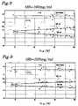
- FIGS. 8 and 9are diagrams which show a sum signal for tHb which is independent of O 2sat .
- FIG. 1shows the different contributions of the individual hemoglobin derivatives RHb, O 2 Hb, COHb and MetHb in the wavelength range between 740 and 880 nm.
- the sum of the two absorption values A 1 and A 2 at wavelengths ⁇ 1 and ⁇ 2is proportional to the tHb of the blood sample and is independent of the oxygen saturation. From Fig. 1 it can also be seen that the absorption coefficient of COHb is approximately the same at both wavelengths, ie ⁇ C ( ⁇ 1 ) corresponds to ⁇ C ( ⁇ 2 ). Due to the small value of the absorption coefficient for COHb and the low concentration of COHb, their product can be neglected in the first approximation for the calculation of the tHb.
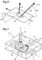
- the measuring arrangementhas a capillary channel 1 for receiving a blood sample, an excitation device 2 for irradiation of at least two measuring wavelengths ⁇ 1 and ⁇ 2, and a detection device 3, the optical axes 2 'and 3' of the excitation device 2 and the detection device 3 on the capillary channel 1 are directed.
- the excitation device 2has a unit 4 which provides the two measurement wavelengths ⁇ 1 and ⁇ 2 and light guide means, for. B. a fiber optic 5 for the supply of light.
- the detection device 3consists of a fiber optic 6 and a detector 7.
- the excitation device 2is assigned a beam opening angle ⁇ for the excitation light cone 8 due to the numerical aperture of the fiber optic 5.
- the detection device 3has a detection cone 9 defined by an acceptance angle ⁇ . Both cones 8 and 9 overlap on the inner wall 10 of the capillary channel 1 when the latter is filled with aqueous solution.
- at least one of the axes 2 'and / or 3'can be inclined to the normal to the axis 1 'of the capillary channel 1 by the angle ⁇ 1 and / or ⁇ 2 .
- the inner wall 10 of the Capillary channel 1at least in the overlap area 11 of the two Provide cones 8 and 9 with a red calibration surface 12.
- This calibration surface 12extends over approximately 20 to 40% the circumference of the inner surface.
- the inside diameter of the Capillary 1is typically 1 mm.
- the capillaryis filled with whole blood filled, which changes the mean penetration depth of the measuring radiation limited to the upper half or upper third of the capillary.
- the two cones 8 and 9overlap no longer, so the measurement by scattering on the blood cells takes place along arrow 13.
- an embodiment variant of the inventioncan be seen, in which the capillary channel 1 in the area 11 of the overlapping excitation light or detection cones 8 and 9 widens to a measuring chamber 14, the circular base area of the measuring chamber 14, for example, being an optical one Has sensor 15.
- the optical sensor 15can, for example, have an indicator for measuring the pO 2 , the pCO 2 or the pH of the whole blood sample in an indicator layer 16 and can be provided with an analyte-permeable cover layer which also serves as a red calibration surface 12.
- the capillary channel 1 with the measuring chamber 14is arranged in a disposable cassette 17 which is constructed in two parts (parts 18 and 19) and can be inserted into an evaluation device (not shown here) which can be inserted via the optical devices 2 and 3.
- the overlap region 11 of the excitation light cone 8 with the detection cone 9can be seen from FIG. 4.
- FIGS. 4 and 5show the measuring arrangement according to FIGS. 4 and 5 in three-dimensional representation, with Fig. 6 on the purely geometric Conditions is turned off.
- 7is a flat one Capillary channel visible, which is aerodynamically favorable expanded into the measuring chamber 14.
- the height of the capillary channel and the measuring chamberis approximately 0.7 mm, the penetration depth of the measuring radiation used with a capillary filled with whole blood 0.3 mm.
- the excitation lightis transmitted through the light guide 5 coupled into the cassette 17 and on the calibration surface 12 reflected in a wavelength-specific manner. That reflected Light can be detected by the receiving optics, whereby has shown that when using at least two Wavelengths at which the calibration surface 12 is different Absorption values and thus also different reflection values shows a calibration size can be specified which is proportional to the coupling and decoupling losses.
- the calibration sizecan e.g. B. from the ratio of the reflection values of the two measuring wavelengths are formed. The ratio number must be in a certain, predetermined range Complete calibration positively. This makes it possible to make cassette-specific Calibrate coupling losses before the measurement. When using more than two measuring wavelengths the accuracy of the calibration can be improved accordingly.
- tHb160mg / ml
- the factor f1.13.
Landscapes
- Health & Medical Sciences (AREA)
- Life Sciences & Earth Sciences (AREA)
- Engineering & Computer Science (AREA)
- Physics & Mathematics (AREA)
- Chemical & Material Sciences (AREA)
- Hematology (AREA)
- Biomedical Technology (AREA)
- Immunology (AREA)
- Pathology (AREA)
- Spectroscopy & Molecular Physics (AREA)
- Molecular Biology (AREA)
- Analytical Chemistry (AREA)
- Biochemistry (AREA)
- General Health & Medical Sciences (AREA)
- General Physics & Mathematics (AREA)
- Urology & Nephrology (AREA)
- Food Science & Technology (AREA)
- Medicinal Chemistry (AREA)
- Biophysics (AREA)
- Biotechnology (AREA)
- Cell Biology (AREA)
- Microbiology (AREA)
- Ecology (AREA)
- Investigating Or Analysing Biological Materials (AREA)
- Measurement Of The Respiration, Hearing Ability, Form, And Blood Characteristics Of Living Organisms (AREA)
- Investigating Or Analysing Materials By Optical Means (AREA)
- Optical Measuring Cells (AREA)
Abstract
Description
Translated fromGermanDie Erfindung betrifft eine Messanordnung zur optischen Bestimmungder totalen Hämoglobinkonzentration in nicht hämolysiertemVollblut, mit einem Kapillarkanal zur Aufnahme einer Blutprobe,einer Anregungseinrichtung zur Einstrahlung von zumindest zweiMesswellenlängen und einer auf der selben Seite der Kapillareangeordneten Detektionseinrichtung, wobei die optischen Achsender Anregungseinrichtung und der Detektionseinrichtung auf denKapillarkanal gerichtet sind, und die Anregungseinrichtungeinen durch einen Strahlöffnungswinkel α definierten, von derAnregungseinrichtung ausgehenden Anregungslichtkegel und dieDetektionseinrichtung einen durch einen Akzeptanzwinkel β definierten,von der Detektionseinrichtung ausgehenden Detektionskegelaufweist.The invention relates to a measuring arrangement for optical determinationthe total hemoglobin concentration in non-hemolyzedWhole blood, with a capillary channel for taking a blood sample,an excitation device for irradiating at least twoMeasuring wavelengths and one on the same side of the capillaryarranged detection device, the optical axesthe excitation device and the detection device on theCapillary channel are directed, and the excitation deviceone defined by a beam opening angle α, of whichExcitation device outgoing excitation light cone and theDetection device defined by an acceptance angle β,detection cone emanating from the detection devicehaving.
Es werden folgende Abkürzungen verwendet:
- Hb
- Hämoglobin
- tHb
- totale Hämoglobinkonzentration (Summe aller aktivenund inaktiven Hämoglobinderivate im Blut)
- O2sat
- Sauerstoffsättigung in Prozent
- O2Hb
- Oxygeniertes Hb
- RHb
- Deoxygeniertes Hb
- COHb
- Carboxy Hb
- MetHb
- Methämoglobin
- SulfHb
- Sulfhämoglobin
- σO
- Absorptionskoeffizient von O2Hb
- σR
- Absorptionskoeffizient von RHb
- σC
- Absorptionskoeffizient von COHb
- σM
- Absorptionskoeffizient von MetHb
- CO
- Konzentration von O2Hb
- CR
- Konzentration von RHb
- CC
- Konzentration von COHb
- Hb
- hemoglobin
- tHb
- total hemoglobin concentration (sum of all active and inactive hemoglobin derivatives in the blood)
- O2sat
- Percent oxygen saturation
- O2 Hb
- Oxygenated Hb
- RHb
- Deoxygenated Hb
- COHb
- Carboxy Hb
- MetHb
- Methaemoglobin
- SulfHb
- Sulfhemoglobin
- σO
- Absorption coefficient of O2 Hb
- σR
- Absorption coefficient of RHb
- σC
- Absorption coefficient of COHb
- σM
- Absorption coefficient of MetHb
- CO
- Concentration of O2 Hb
- CR
- Concentration of RHb
- CC
- Concentration of COHb
Eine Messanordnung der eingangs genannten Art ist beispielsweiseaus der US-A 5 061 632 bekannt geworden. Das hier beschriebene Oximeter zur Bestimmung von tHb und O2sat weist eineKapillare zur Aufnahme einer nicht hämolysierten Vollblutprobeauf, welche in die zentrale Bohrung einer zylindrischen Auswerteeinheiteingeführt werden kann. Die Auswerteeinheit weist inaxialem Abstand zwei auf die Zentralbohrung im rechten Winkelangeordnete Radialbohrungen auf, über welche die Messstrahlungaus zwei LEDs zugeführt wird. In axialer Erstreckung zwischenden beiden Radialbohrungen für die Lichtzufuhr ist eine weiteresenkrecht auf die Zentralbohrung stehende Radialbohrung angeordnet,welche das von der Probe emittierte Licht einem am Mantelder zylindrischen Auswerteeinheit angeordneten Detektor zuführt.Die erste Diode gibt Infrarotstrahlung mit einer Wellenlängevon ca. 800 nm ab und dient zur Bestimmung des tHb. Damitdie Messung weitgehend unabhängig von der Verteilung von O2Hbzu RHb ist, wird die Messung möglichst nahe beim isosbestischenPunkt der Absorptionskoeffizienten von O2Hb und RHb durchgeführt.Ein derartiger Punkt liegt bei ca. 805 nm (siehe z. B.IEEE Transactions on Biomedical Engineering Vol.35. No. 3, März1988). Die zweite Diode emittiert rotes Licht einer Wellenlängevon 660 nm und dient zur Bestimmung der SauerstoffsättigungO2sat, da bei dieser Wellenlänge ein signifikanter Unterschiedder Absorptionskoeffizienten für O2Hb und RHb besteht. Die Beiträgeder übrigen Hämoglobinderivate (COHb, MetHb und SulfHb)werden bei der genannten Messanordnung nicht berücksichtigt.Der Fehler für die O2sat Bestimmung liegt dadurch bei ca. 1 bis15%.A measuring arrangement of the type mentioned at the outset has become known, for example, from US Pat. No. 5,061,632. The oximeter described here for determining tHb and O2sat has a capillary for receiving a non-hemolyzed whole bloodsample , which can be inserted into the central bore of a cylindrical evaluation unit. At an axial distance, the evaluation unit has two radial bores, which are arranged at right angles to the central bore and through which the measurement radiation is supplied from two LEDs. In the axial extent between the two radial bores for the supply of light there is a further radial bore which is perpendicular to the central bore and which feeds the light emitted by the sample to a detector arranged on the jacket of the cylindrical evaluation unit. The first diode emits infrared radiation with a wavelength of approx. 800 nm and is used to determine the tHb. So that the measurement is largely independent of the distribution of O2 Hb to RHb, the measurement is carried out as close as possible to the isosbestic point of the absorption coefficients of O2 Hb and RHb. Such a point is approximately 805 nm (see, for example, IEEE Transactions on Biomedical Engineering Vol. 35. No. 3, March 1988). The second diode emits red light with a wavelength of 660 nm and is used to determine the oxygen saturation O2sat , since there is a significant difference in the absorption coefficients for O2 Hb and RHb at this wavelength. The contributions of the other hemoglobin derivatives (COHb, MetHb and SulfHb) are not taken into account in the measurement arrangement mentioned. The error for the O2sat determination is therefore approx. 1 to 15%.
Aus der WO 94/08237 ist ein Verfahren und eine Vorrichtung fürdirekte spektrofotometrische Messungen in unverdünntem Vollblutbeschrieben, bei welchen Messwellenlängen λ1 bis λn in dieProbe eingestrahlt und unter einem großen Detektionswinkel erfasstwerden. Es wird somit eine Absorptionsmessung unter Berücksichtigungdes gestreuten Anteils des eingestrahlten Lichtesbei einer definierten Anzahl von Messwellenlängen durchgeführt.Zur Auswertung muss ein nichtlineares Gleichungssystemgelöst werden, wobei der Anteil der Nichtlinearität von derProbenstärke abhängig ist.WO 94/08237 describes a method and a device for direct spectrophotometric measurements in undiluted whole blood, at which measuring wavelengths λ1 to λn are irradiated into the sample and detected at a large detection angle. An absorption measurement is thus carried out taking into account the scattered portion of the incident light at a defined number of measuring wavelengths. A nonlinear system of equations must be solved for the evaluation, the proportion of nonlinearity depending on the sample strength.
Allgemein sind reproduzierbare Ergebnisse in derartigen Messanordnungennur dann gewährleistet, wenn keine Veränderungen im optischen Pfad auftreten. Veränderungen werden vor allem durchunterschiedliche Ein- und Auskoppelverluste verursacht, da beiStreulichtmessungen die Weglänge durch die Probe undefiniertist. Wird nun eine austauschbare Küvette oder Kassette (Einmalsensor)verwendet, ergeben sich nur bedingt reproduzierbareEin- und Auskoppelfaktoren für das Licht, bedingt durch nichtplane, unterschiedliche Oberflächen der einzelnen Küvetten bzw.Kassetten (Polarisationseffekte, Streuung etc.).In general, reproducible results are in such measuring arrangementsonly guaranteed if there are no changes in theoptical path occur. Changes are mainly due todifferent coupling and decoupling losses caused because atScattered light measurements undefined the path length through the sampleis. If an exchangeable cuvette or cassette (disposable sensor)used, only reproducible to a limited extentCoupling and decoupling factors for the light, caused by notflat, different surfaces of the individual cuvettes orCassettes (polarization effects, scattering, etc.).
Aus der DD 203 632 A ist ein Schnellverfahren und eine Einrichtungzur fotometrischen Bestimmung der Konzentration von COHbbekannt geworden. Es wird mit zwei Messwellenlängen operiert,wobei als Lichtquellen Luminszenzdioden mit einer maximalenspektralen Emission bei 565 nm und 940 nm verwendet werden. AlsLichtempfänger dienen Festkörperfotodetektoren, welche unmittelbarauf die Probe gerichtet sind, die als mit dem Untersuchungsmaterialgetränktes spezielles Filterpapier vorliegt. ZurBestimmung der spektralen Absorption werden die Remissionund/oder die Transmission ausgewertet, wobei die COHb Konzentrationüber einen Rechner ausgegeben wird.DD 203 632 A is a quick process and a devicefor the photometric determination of the concentration of COHbknown. It is operated with two measuring wavelengths,where as light sources luminescent diodes with a maximumspectral emission at 565 nm and 940 nm can be used. AsLight receivers serve solid-state photo detectors, which are immediateare directed at the sample as with the test materialimpregnated special filter paper. ForDetermination of the spectral absorption will be the remissionand / or the transmission is evaluated, the COHb concentrationis output via a computer.
Aus der AT-E 56 271 B ist ein Verfahren zur spektrofotometrischenBestimmung der Konzentration einer Anzahl von Hämoglobinderivatenin Vollblut bekannt, wobei mehrere unterschiedlicheWellenlängen in die Blutprobe eingestrahlt und Absorptionswertegemessen werden. Die Konzentrationen der einzelnen Hämoglobinderivatewerden durch Lösen eines Gleichungssystems bestimmt.AT-E 56 271 B describes a method for spectrophotometricDetermination of the concentration of a number of hemoglobin derivativesknown in whole blood, with several differentWavelengths radiated into the blood sample and absorption valuesbe measured. The concentrations of the individual hemoglobin derivativesare determined by solving a system of equations.
Weitere fotometrische Methoden zur Messung von Blutbestandteilensind aus der US-A 5 127 406 und der US-A 5 064 282 bekannt.Other photometric methods for measuring blood componentsare known from US-A 5 127 406 and US-A 5 064 282.
Aufgabe der Erfindung ist es, eine Messanordnung zur optischenBestimmung der totalen Hämoglobinkonzentration in nichthämolysiertemVollblut vorzuschlagen, wobei das Problem der sich änderndenEin- und Auskoppelverluste gelöst werden soll. DieMessanordnung soll auch zur Bestimmung der Sauerstoffsättigungund für austauschbare Einwegkassetten verwendbar sein.The object of the invention is to provide a measuring arrangement for opticalDetermination of the total hemoglobin concentration in non-hemolyzedTo propose whole blood, the problem being changingCoupling and decoupling losses should be solved. TheMeasuring arrangement is also intended to determine oxygen saturationand can be used for interchangeable disposable cartridges.
Diese Aufgabe wird erfindungsgemäß dadurch gelöst, dass dieNeigungswinkel der optischen Achsen und deren Abstand an derSchnittstelle mit der Kapillare derart auf den Kapillardurchmesser abgestimmt sind, dass sich der Anregungslichtkegel undder Detektionskegel bei mit wässriger Lösung gefülltem Kapillarkanalan der der Anregungseinrichtung und der Detektionseinrichtunggegenüberliegenden Innenwand des Kapillarkanals überlappenund bei mit Vollblut gefülltem Kapillarkanal, bedingtdurch die verringerte mittlere Eindringtiefe der Messstrahlung,nicht überlappen, sowie dass die Innenwand des Kapillarkanalsfür die verwendeten Messwellenlängen λ1, λ2 unterschiedlicheReflexionswerte aufweist.This object is achieved according to the invention in that the angles of inclination of the optical axes and their distance at the interface with the capillary are matched to the capillary diameter in such a way that the excitation light cone and the detection cone, when the capillary channel is filled with aqueous solution, on the opposite side of the excitation device and the detection device Overlap the inner wall of the capillary channel and, when the capillary channel is filled with whole blood, do not overlap due to the reduced mean penetration depth of the measuring radiation, and that the inner wall of the capillary channel has different reflection values for the measuring wavelengths λ1 , λ2 used .
Durch die Überlappung des Anregungslichtkegels und des Detektionskegelsbei mit wässriger Lösung, beispielsweise einer Kalibrierlösung,gefülltem Kapillarkanal kann somit eine Leermessungdurchgeführt werden, bei welcher das Messlicht, behaftetmit Ein- und Auskoppelverlusten, nach einer Reflexion an derInnenwand des Kapillarkanals in die Detektionseinrichtung gelangt.Durch die Verwendung zumindest zweier Messwellenlängenkönnen die unterschiedlichen optischen Verluste vor jeder Messungerfasst werden. Dabei muss die Innenwand der Kapillare unterschiedlicheReflexionswerte bei den beiden Messwellenlängenaufweisen um brauchbare Kalibriergrößen ableiten zu können.Insbesondere auch dann, wenn der Kapillarkanal gemäß einer bevorzugtenAusführung der Erfindung in einer Einwegkassette angeordnetist, welche in ein die Anregungs- und Detektionseinrichtungaufweisendes Auswertegerät einbringbar ist.Due to the overlap of the excitation light cone and the detection conewith an aqueous solution, for example a calibration solution,filled capillary channel can therefore be an empty measurementbe carried out in which the measuring light, afflictedwith coupling and decoupling losses, after reflection on theInner wall of the capillary channel reaches the detection device.By using at least two measuring wavelengthscan the different optical losses before each measurementbe recorded. The inner wall of the capillary must be differentReflection values at the two measuring wavelengthsto be able to derive usable calibration values.In particular, even if the capillary channel according to a preferredExecution of the invention arranged in a disposable cassettewhich is in the excitation and detection devicehaving evaluation device can be introduced.
Es ist weiters von Vorteil, wenn die Messanordnung eine ersteMesswellenlänge mit λ1 < 805 nm und eine zweite Messwellenlängemit λ2 > 805 nm bereit stellt, derart, dass für die AbsorptionskoeffizientenσO(λ) und σR(λ) der Hämoglobinderivate O2Hbund RHb bei den beiden Messwellenlängen λ1 und λ2 gilt: σO(λ1)ungefähr gleich σR(λ2) und σR(λ1) ungefähr gleich σO(λ2).Eskönnen dann bei den Wellenlängen λ1 und λ2 die AbsorptionswerteA1 und A2 bestimmt werden, wobei die Summe der beiden AbsorptionswerteA1 + A2 eine zur totalen Hämoglobinkonzentration tHbproportionale, von der Sauerstoffsättigung O2sat unabhängigeGröße ist.It is furthermore advantageous if the measuring arrangement provides a first measuring wavelength with λ1 <805 nm and a second measuring wavelength with λ2 > 805 nm, such that for the absorption coefficients σO (λ) and σR (λ) of the hemoglobin derivatives O2 Hb and RHb for the two measuring wavelengths λ1 and λ2 : σO (λ1 ) approximately equal to σR (λ2 ) and σR (λ1 ) approximately equal to σO (λ2 ). It is then possible to use the wavelengths λ1 and λ2 the absorption values A1 and A2 are determined, the sum of the two absorption values A1 + A2 being a variable which is proportional to the total hemoglobin concentrationtHb and is independent of the oxygen saturation O2sat .
Die Messanordnung verwendet somit zwei isosbestisch symmetrischeWellenlängen, wobei durch die gewählten Wellenlängen mitherkömmlichen Laserdioden die selben Vorteile erzielt werden, welche eine Messung direkt am isosbestischen Punkt ermöglichenwürde. Die Absorptionskoeffizienten von O2Hb und RHb solltendabei bei den beiden Wellenlängen λ1 und λ2 jeweils nur um± 5 % von einander abweichen. Weiters ist die Messung weitgehendunabhängig von der Sauerstoffsättigung der Probe.The measuring arrangement thus uses two isosbestically symmetrical wavelengths, the wavelengths chosen using conventional laser diodes achieving the same advantages which would make measurement directly at the isosbestic point possible. The absorption coefficients of O2 Hb and RHb should differ from each other by only ± 5% at the two wavelengths λ1 and λ2 . Furthermore, the measurement is largely independent of the oxygen saturation of the sample.
Zur Kompensation unterschiedlicher Anregungsintensitäten I1 undI2 bei den Wellenlängen λ1 und λ2 kann ein Korrekturfaktor feingeführt werden, derart, dass die totale HämoglobinkonzentrationtHb der Summe A1 + f.A2 proportional ist, wobei der Faktorf zwischen 0,5 und 2,0 liegt und eine von der gewählten Messanordnungabhängige Kalibriergröße ist.In order to compensate for different excitation intensities I1 and I2 at the wavelengths λ1 and λ2 , a correction factor f can be introduced such that the total hemoglobin concentration tHb is proportional to the sum A1 + fA2 , the factor f being between 0.5 and 2.0 and is a calibration variable depending on the selected measuring arrangement.
Vorteilhafte Messwellenlängen für λ1 liegen zwischen 780 und790 nm, vorzugsweise bei 785 ± 3 nm sowie für λ2 zwischen 830und 850 nm, vorzugsweise bei 836 ± 3 nm. Für die genannten Wellenlängensind Standardlaserdioden verfügbar (780 bis 785 nmbzw. 840 bis 850 nm) die eine scharf begrenzte Emissionswellenlängeabstrahlen.Advantageous measuring wavelengths for λ1 are between 780 and 790 nm, preferably at 785 ± 3 nm and for λ2 between 830 and 850 nm, preferably at 836 ± 3 nm. Standard laser diodes are available for the wavelengths mentioned (780 to 785 nm or 840 up to 850 nm) which emit a sharply limited emission wavelength.
Die Sauerstoffsättigung O2sat kann aus den ermittelten AbsorptionswertenA1 und A2 näherungsweise durch die Formel
Für die Bestimmung der Sauerstoffsättigung kann jedoch aucheine dritte Messwellenlänge verwendet werden, wobei jedeWellenlänge zulässig ist, bei welcher die AbsorptionskoeffizientenσR und σO für RHb und O2Hb möglichst große Unterschiedeaufweisen. Eine günstige Wellenlänge liegt beispielsweise bei680 nm (geringer Einfluss von MetHb).However, a third measuring wavelength can also be used to determine the oxygen saturation, any wavelength being permissible at which the absorption coefficients σR and σO for RHb and O2 Hb differ as much as possible. A favorable wavelength is, for example, 680 nm (little influence of MetHb).
Im Hinblick auf die verwendeten Messwellenlängen ist es vonVorteil, dass die Innenwand des Kapillarkanals zumindest imBereich des sich mit dem Anregungslichtkegel überlappenden Detektionskegeleine rote Kalibrierfläche aufweist. Dabei ist esvon Vorteil, wenn die rote Kalibrierfläche einen Mantelbereichder Innenfläche des Kapillarkanals bedeckt, welcher sich überca. 20 bis 40 % des Umfangs erstreckt und der Anregungs- undDetektionseinrichtung gegenüberliegt.With regard to the measuring wavelengths used, it is fromAdvantage that the inner wall of the capillary channel at least inArea of the detection cone overlapping with the excitation light conehas a red calibration surface. It isof advantage if the red calibration surface is a cladding areathe inner surface of the capillary channel, which overlapsextends about 20 to 40% of the scope and the excitation andDetection device is opposite.
In einer weiteren Ausgestaltung der Erfindung ist vorgesehen,dass sich der Kapillarkanal im Bereich der sich überlappendenAnregungslicht- bzw. Detektionskegel zu einer Messkammer erweitert,wobei eine Wand der Messkammer einen optischen Sensoraufweist, dessen für den zu messenden Parameter permeable Deckschichtals rote Kalibrierfläche ausgeführt ist. Zum Beispielkann der optische Sensor eine Indikatorschicht mit einem Indikatorzur Messung des pO2 in der Vollblutprobe aufweisen.In a further embodiment of the invention, it is provided that the capillary channel widens in the area of the overlapping excitation light or detection cones to form a measuring chamber, one wall of the measuring chamber having an optical sensor, the cover layer of which is permeable for the parameter to be measured, is designed as a red calibration surface is. For example, the optical sensor can have an indicator layer with an indicator for measuring the pO2 in the whole blood sample.
Die Erfindung wird im folgenden anhand von zum Teil schematischenZeichnungen näher erläutert. Es zeigen Fig. 1 ein Diagrammmit der von der Wellenlänge abhängigen unterschiedlichenAbsorption der einzelnen Hämoglobinderivate, Fig. 2 eine ersteAusführungsvariante einer erfindungsgemäßen Messanordnung,Fig. 3 die Messanordnung gemäß Fig. 2, geschnitten entlang der Linie III-III in Fig. 2, die Fig. 4 bis 7 eine weitere Ausführungsvarianteder erfindungsgemäßen Messanordnung, sowie Fig. 8und 9 Diagramme, welche ein von O2sat unabhängiges Summensignalfür tHb zeigen.The invention is explained in more detail below with the aid of partly schematic drawings. 1 shows a diagram with the different absorption of the individual hemoglobin derivatives depending on the wavelength, FIG. 2 shows a first embodiment variant of a measuring arrangement according to the invention, FIG. 3 shows the measuring arrangement according to FIG. 2, cut along the line III-III in FIG. 2 4 to 7 show a further embodiment variant of the measuring arrangementaccording to the invention, and FIGS. 8 and 9 are diagrams which show a sum signal for tHb which is independent of O2sat .
Aus Fig. 1 sind die unterschiedlichen Beiträge der einzelnenHämoglobinderivate RHb, O2Hb, COHb und MetHb im Wellenlängenbereichzwischen 740 und 880 nm dargestellt. Ein isosbestischerPunkt für die Hauptbestandteile RHb und O2Hb liegt beiλi = 805 nm. Aus der Abbildung ist weiters ersichtlich, dassfür die eingezeichneten Wellenlängen λ1 = 785 nm undλ2 = 836 nm
Die Fig. 2 und 3 zeigen eine erste Ausführungsvariante einererfindungsgemäßen Messanordnung zur optischen Bestimmung destHb in nicht hämolysiertem Vollblut. Die Messanordnung weisteinen Kapillarkanal 1 zur Aufnahme einer Blutprobe, eine Anregungseinrichtung2 zur Einstrahlung von zumindest zwei Messwellenlängenλ1 und λ2 sowie eine Detektionseinrichtung 3 auf,wobei die optischen Achsen 2' und 3' der Anregungseinrichtung 2und der Detektionseinrichtung 3 auf den Kapillarkanal 1 gerichtetsind. Die Anregungseinrichtung 2 weist eine Einheit 4, welchedie zwei Messwellenlängen λ1 und λ2 zur Verfügung stelltund Lichtleitmittel, z. B. eine Faseroptik 5, zur Lichtzufuhrauf. Desgleichen besteht die Detektionseinrichtung 3 aus einerFaseroptik 6 und einem Detektor 7. Der Anregungseinrichtung 2ist bedingt durch die numerische Apertur der Faseroptik 5 einStrahlöffnungswinkel α für den Anregungslichtkegel 8 zugeordnet.Desgleichen weist die Detektionseinrichtung 3 einen durcheinen Akzeptanzwinkel β definierten Detektionskegel 9 auf.Beide Kegel 8 und 9 überlappen sich an der Innenwand 10 des Kapillarkanals 1, wenn dieser mit wässriger Lösung gefüllt ist.Um einen genügend großen Überlappungsbereich 11 der beiden Kegel8 und 9 zu erreichen, kann zumindest eine der Achsen 2'und/oder 3' zur Normale auf die Achse 1' des Kapillarkanals 1um den Winkel β1 und/oder β2 geneigt sein. Durch Variation derEntfernung e zwischen der Anregungseinrichtung 2 und der Detektionseinrichtung3 sowie durch Veränderung der beiden Winkel β1und β2 kann die Sensitivität bei der Messung und der Kalibrierungoptimiert werden.2 and 3 show a first embodiment variant of a measuring arrangement according to the invention for the optical determination of the tHb in non-hemolyzed whole blood. The measuring arrangement has a capillary channel 1 for receiving a blood sample, an excitation device 2 for irradiation of at least two measuring wavelengths λ1 and λ2, and a detection device 3, the optical axes 2 'and 3' of the excitation device 2 and the detection device 3 on the capillary channel 1 are directed. The excitation device 2 has a unit 4 which provides the two measurement wavelengths λ1 and λ2 and light guide means, for. B. a fiber optic 5 for the supply of light. Likewise, the detection device 3 consists of a fiber optic 6 and a detector 7. The excitation device 2 is assigned a beam opening angle α for the excitation light cone 8 due to the numerical aperture of the fiber optic 5. Likewise, the detection device 3 has a detection cone 9 defined by an acceptance angle β. Both cones 8 and 9 overlap on the inner wall 10 of the capillary channel 1 when the latter is filled with aqueous solution. In order to achieve a sufficiently large overlap area 11 of the two cones 8 and 9, at least one of the axes 2 'and / or 3' can be inclined to the normal to the axis 1 'of the capillary channel 1 by the angle β1 and / or β2 . By varying the distance e between the excitation device 2 and the detection device 3 and by changing the two angles β1 and β2 , the sensitivity during the measurement and calibration can be optimized.
Für die Kalibrierung der Messanordnung ist die Innenwand 10 desKapillarkanals 1 zumindest im Überlappungsbereich 11 der beidenKegel 8 und 9 mit einer roten Kalibrierfläche 12 versehen.Diese Kalibrierfläche 12 erstreckt sich über ca. 20 bis 40 %des Umfanges der inneren Mantelfläche. Der Innendurchmesser derKapillare 1 beträgt typischerweise 1 mm.For the calibration of the measuring arrangement, the inner wall 10 of theCapillary channel 1 at least in the overlap area 11 of the twoProvide cones 8 and 9 with a red calibration surface 12.This calibration surface 12 extends over approximately 20 to 40%the circumference of the inner surface. The inside diameter of theCapillary 1 is typically 1 mm.
Nach Abschluss der Kalibrierung wird die Kapillare mit Vollblutgefüllt, wodurch sich die mittlere Eindringtiefe der Messstrahlungauf die obere Hälfte bzw. obere Drittel der Kapillare beschränkt.Die beiden Kegel 8 und 9 überlappen sich dadurchnicht mehr, sodass die Messung durch Streuung an den Blutzellenentlang des Pfeiles 13 erfolgt.After the calibration is complete, the capillary is filled with whole bloodfilled, which changes the mean penetration depth of the measuring radiationlimited to the upper half or upper third of the capillary.As a result, the two cones 8 and 9 overlapno longer, so the measurement by scattering on the blood cellstakes place along arrow 13.
Aus den Fig. 4 und 5 ist eine Ausführungsvariante der Erfindungersichtlich, bei welcher sich der Kapillarkanal 1 im Bereich 11der sich überlappenden Anregungslicht- bzw. Detektionskegel 8und 9 zu einer Messkammer 14 erweitert, wobei die beispielsweisekreisförmige Grundfläche der Messkammer 14 einen optischenSensor 15 aufweist. Der optische Sensor 15 kann beispielsweisein einer Indikatorschicht 16 einen Indikator zurMessung des pO2, des pCO2 oder des pH-Wertes der Vollblutprobeaufweisen und mit einer analytpermeablen Deckschicht versehensein, welche gleichzeitig als rote Kalibrierfläche 12 dient.Der Kapillarkanal 1 mit der Messkammer 14 ist in der Ausführungsvariantegemäß Fig. 4 und 5 in einer Einwegkassette 17 angeordnet,welche zweiteilig (Teile 18 und 19) aufgebaut ist undin ein hier nicht weiter dargestelltes Auswertegerät einbringbarist, welches über die optischen Einrichtungen 2 und 3 verfügt.Aus Fig. 4 ist der Überlappungsbereich 11 des Anregungslichtkegels8 mit dem Detektionskegel 9 erkennbar.4 and 5, an embodiment variant of the invention can be seen, in which the capillary channel 1 in the area 11 of the overlapping excitation light or detection cones 8 and 9 widens to a measuring chamber 14, the circular base area of the measuring chamber 14, for example, being an optical one Has sensor 15. The optical sensor 15 can, for example, have an indicator for measuring the pO2 , the pCO2 or the pH of the whole blood sample in an indicator layer 16 and can be provided with an analyte-permeable cover layer which also serves as a red calibration surface 12. 4 and 5, the capillary channel 1 with the measuring chamber 14 is arranged in a disposable cassette 17 which is constructed in two parts (parts 18 and 19) and can be inserted into an evaluation device (not shown here) which can be inserted via the optical devices 2 and 3. The overlap region 11 of the excitation light cone 8 with the detection cone 9 can be seen from FIG. 4.
Die Fig. 6 und 7 zeigen die Messanordnung gemäß Fig. 4 und 5 indreidimensionaler Darstellung, wobei Fig. 6 auf die rein geometrischenGegebenheiten abgestellt ist. Aus Fig. 7 ist ein flacherKapillarkanal ersichtlich, welcher sich strömungsgünstigin die Messkammer 14 erweitert. Die Höhe des Kapillarkanals undder Messkammer beträgt ungefähr 0,7 mm, die Eindringtiefe derverwendeten Messstrahlung bei mit Vollblut gefüllter Kapillareca. 0,3 mm.6 and 7 show the measuring arrangement according to FIGS. 4 and 5 inthree-dimensional representation, with Fig. 6 on the purely geometricConditions is turned off. 7 is a flat oneCapillary channel visible, which is aerodynamically favorableexpanded into the measuring chamber 14. The height of the capillary channel andthe measuring chamber is approximately 0.7 mm, the penetration depth of themeasuring radiation used with a capillary filled with whole blood0.3 mm.
Bei der Kalibrierung wird das Anregungslicht über den Lichtleiter5 in die Kassette 17 eingekoppelt und an der Kalibrierfläche12 wellenlängenspezifisch reflektiert. Das reflektierteLicht kann von der Empfangsoptik detektiert werden, wobei sichherausgestellt hat, dass bei Verwendung von mindestens zweiWellenlängen, bei welchen die Kalibrierfläche 12 unterschiedlichAbsorptionswerte und damit auch unterschiedliche Reflexionswertezeigt, eine Kalibriergröße angegeben werden kann,die den Ein- und Auskoppelverlusten proportional ist. Die Kalibriergrößekann z. B. aus dem Verhältnis der Reflexionswerteder beiden Messwellenlängen gebildet werden. Die Verhältniszahlmuss in einem bestimmten, vorgegebenen Bereich liegen um dieKalibrierung positiv abzuschließen. Damit ist es möglich, kassettenspezifischeAnkoppelverluste vor der Messung zu kalibrieren.Bei der Verwendung von mehr als zwei Messwellenlängen kanndie Genauigkeit der Kalibrierung entsprechend verbessert werden.During calibration, the excitation light is transmitted through the light guide5 coupled into the cassette 17 and on the calibration surface12 reflected in a wavelength-specific manner. That reflectedLight can be detected by the receiving optics, wherebyhas shown that when using at least twoWavelengths at which the calibration surface 12 is differentAbsorption values and thus also different reflection valuesshows a calibration size can be specifiedwhich is proportional to the coupling and decoupling losses. The calibration sizecan e.g. B. from the ratio of the reflection valuesof the two measuring wavelengths are formed. The ratio numbermust be in a certain, predetermined rangeComplete calibration positively. This makes it possible to make cassette-specificCalibrate coupling losses before the measurement.When using more than two measuring wavelengthsthe accuracy of the calibration can be improved accordingly.
Die Diagramme in den Fig. 8 und 9, bei welchen auf der Ordinatedie Absorption A und auf der Abszisse die SauerstoffsättigungO2sat in Prozent aufgetragen ist, zeigen, dass das SummensignalA1+f.A2 der Absorptionswerte A1 und A2 bei den Wellenlängenλ1= 780 nm und λ2= 850 nm für unterschiedliche Werte vonO2sat konstant ist. In Fig. 8 beträgt tHb = 160mg/ml in Fig. 9tHb = 220mg/ml. Der Faktor f = 1.13.The diagrams in FIGS. 8 and 9, in which the absorption A is plotted on the ordinate and the oxygen saturation O2sat in percent on the abscissa, show that the sum signal A1 + fA2 of the absorption values A1 and A2 in the Wavelengths λ1 = 780 nm and λ2 = 850 nm is constant for different values of O2sat . In Fig. 8, tHb = 160mg / ml in Fig. 9 is tHb = 220mg / ml. The factor f = 1.13.
Claims (8)
Translated fromGermanApplications Claiming Priority (3)
| Application Number | Priority Date | Filing Date | Title |
|---|---|---|---|
| AT126296 | 1996-07-12 | ||
| AT0126296AAT404513B (en) | 1996-07-12 | 1996-07-12 | METHOD AND MEASURING ARRANGEMENT FOR THE OPTICAL DETERMINATION OF TOTAL HEMOGLOBIN CONCENTRATION |
| EP97890130AEP0818682B1 (en) | 1996-07-12 | 1997-07-09 | Method and device for the optical measurement of the total hemoglobin concentration |
Related Parent Applications (1)
| Application Number | Title | Priority Date | Filing Date |
|---|---|---|---|
| EP97890130ADivisionEP0818682B1 (en) | 1996-07-12 | 1997-07-09 | Method and device for the optical measurement of the total hemoglobin concentration |
Publications (2)
| Publication Number | Publication Date |
|---|---|
| EP1028318A1true EP1028318A1 (en) | 2000-08-16 |
| EP1028318B1 EP1028318B1 (en) | 2003-10-29 |
Family
ID=3510088
Family Applications (2)
| Application Number | Title | Priority Date | Filing Date |
|---|---|---|---|
| EP00107256AExpired - LifetimeEP1028318B1 (en) | 1996-07-12 | 1997-07-09 | Device for the optical measurement of the total hemoglobin concentration |
| EP97890130AExpired - LifetimeEP0818682B1 (en) | 1996-07-12 | 1997-07-09 | Method and device for the optical measurement of the total hemoglobin concentration |
Family Applications After (1)
| Application Number | Title | Priority Date | Filing Date |
|---|---|---|---|
| EP97890130AExpired - LifetimeEP0818682B1 (en) | 1996-07-12 | 1997-07-09 | Method and device for the optical measurement of the total hemoglobin concentration |
Country Status (5)
| Country | Link |
|---|---|
| US (2) | US5773301A (en) |
| EP (2) | EP1028318B1 (en) |
| JP (1) | JP3000350B2 (en) |
| AT (1) | AT404513B (en) |
| DE (2) | DE59710933D1 (en) |
Cited By (1)
| Publication number | Priority date | Publication date | Assignee | Title |
|---|---|---|---|---|
| GB2397375A (en)* | 2003-01-14 | 2004-07-21 | Hypoguard Ltd | Measuring analyte concentration in a fluid sample by illuminating the sample at two wavelengths |
Families Citing this family (63)
| Publication number | Priority date | Publication date | Assignee | Title |
|---|---|---|---|---|
| US6306347B1 (en)* | 1998-01-21 | 2001-10-23 | Bayer Corporation | Optical sensor and method of operation |
| JP3110017B2 (en)* | 1998-05-26 | 2000-11-20 | 株式会社テイエフビー | Method for measuring antioxidant ability of sample and method for diagnosing diabetes and hyperlipidemia using the same |
| DK1086366T3 (en)* | 1998-06-12 | 2010-08-09 | Radiometer Medical Aps | Method for quality control of a spectrophotometer |
| WO2000001294A1 (en) | 1998-07-04 | 2000-01-13 | Whitland Research Limited | Non-invasive measurement of blood analytes |
| DE19844500A1 (en)* | 1998-09-29 | 2000-03-30 | Roche Diagnostics Gmbh | Process for the photometric evaluation of test elements |
| US6144444A (en)* | 1998-11-06 | 2000-11-07 | Medtronic Avecor Cardiovascular, Inc. | Apparatus and method to determine blood parameters |
| SE9804142D0 (en) | 1998-11-30 | 1998-11-30 | Gambro Ab | Method and device for providing a signal |
| US6187592B1 (en)* | 1998-12-23 | 2001-02-13 | Sandia Corporation | Method for determining properties of red blood cells |
| JP4834265B2 (en)* | 1999-06-16 | 2011-12-14 | ハッチンソン テクノロジー インコーポレーティッド | Total hemoglobin concentration measurement |
| US6611320B1 (en)* | 1999-09-08 | 2003-08-26 | Optoq Ab | Method and apparatus |
| US6540675B2 (en) | 2000-06-27 | 2003-04-01 | Rosedale Medical, Inc. | Analyte monitor |
| US7029628B2 (en) | 2000-12-28 | 2006-04-18 | Stat-Chem Inc. | Portable co-oximeter |
| US6678542B2 (en) | 2001-08-16 | 2004-01-13 | Optiscan Biomedical Corp. | Calibrator configured for use with noninvasive analyte-concentration monitor and employing traditional measurements |
| US6989891B2 (en)* | 2001-11-08 | 2006-01-24 | Optiscan Biomedical Corporation | Device and method for in vitro determination of analyte concentrations within body fluids |
| US7050157B2 (en)* | 2001-11-08 | 2006-05-23 | Optiscan Biomedical Corp. | Reagent-less whole-blood glucose meter |
| US7009180B2 (en)* | 2001-12-14 | 2006-03-07 | Optiscan Biomedical Corp. | Pathlength-independent methods for optically determining material composition |
| US6862534B2 (en)* | 2001-12-14 | 2005-03-01 | Optiscan Biomedical Corporation | Method of determining an analyte concentration in a sample from an absorption spectrum |
| SE0104443D0 (en)* | 2001-12-28 | 2001-12-28 | Hemocue Ab | Analysis method and cuvette for that |
| US7004928B2 (en) | 2002-02-08 | 2006-02-28 | Rosedale Medical, Inc. | Autonomous, ambulatory analyte monitor or drug delivery device |
| US20040132168A1 (en)* | 2003-01-06 | 2004-07-08 | Peter Rule | Sample element for reagentless whole blood glucose meter |
| US7052652B2 (en) | 2003-03-24 | 2006-05-30 | Rosedale Medical, Inc. | Analyte concentration detection devices and methods |
| US7271912B2 (en)* | 2003-04-15 | 2007-09-18 | Optiscan Biomedical Corporation | Method of determining analyte concentration in a sample using infrared transmission data |
| JP2004343275A (en)* | 2003-05-14 | 2004-12-02 | Murata Mach Ltd | Image processing system and scanner |
| AT412515B (en) | 2003-08-07 | 2005-03-25 | Hoffmann La Roche | METHOD FOR DETECTING A GAS BUBBLE IN A LIQUID |
| JP2005274568A (en)* | 2004-03-22 | 2005-10-06 | Spectromedical Inc | Spectroscopic method and apparatus for total hemoglobin measurement |
| US20060189925A1 (en)* | 2005-02-14 | 2006-08-24 | Gable Jennifer H | Methods and apparatus for extracting and analyzing a component of a bodily fluid |
| US20070103678A1 (en)* | 2005-02-14 | 2007-05-10 | Sterling Bernhard B | Analyte detection system with interferent identification and correction |
| US20060281187A1 (en) | 2005-06-13 | 2006-12-14 | Rosedale Medical, Inc. | Analyte detection devices and methods with hematocrit/volume correction and feedback control |
| RU2423073C2 (en)* | 2005-07-14 | 2011-07-10 | Нано-Дайтек Корпорейшн | Nicrofluidic devices and methods of their preparation and application |
| US7426407B2 (en)* | 2005-09-13 | 2008-09-16 | Edwards Lifesciences Corp | Continuous spectroscopic measurement of total hemoglobin |
| US8801631B2 (en) | 2005-09-30 | 2014-08-12 | Intuity Medical, Inc. | Devices and methods for facilitating fluid transport |
| EP1928302B1 (en) | 2005-09-30 | 2012-08-01 | Intuity Medical, Inc. | Fully integrated wearable or handheld monitor |
| US7790464B2 (en)* | 2006-05-04 | 2010-09-07 | Blaze Medical Devices, LLC | Blood hemolysis analyzer |
| DE102006029899B4 (en) | 2006-06-29 | 2009-06-04 | Fresenius Medical Care Deutschland Gmbh | Spectroscopic detector and method for the determination of blood and biological markers in liquids |
| US8597190B2 (en) | 2007-05-18 | 2013-12-03 | Optiscan Biomedical Corporation | Monitoring systems and methods with fast initialization |
| US8175668B1 (en) | 2007-10-23 | 2012-05-08 | Pacesetter, Inc. | Implantable multi-wavelength venous oxygen saturation and hematocrit sensor and method |
| KR101423770B1 (en)* | 2008-01-08 | 2014-07-25 | 엘지전자 주식회사 | Method and Apparatus For The Quantitative Determination Of Hemoglobin Using Whole Blood And Hemolysis |
| US20090247853A1 (en)* | 2008-03-31 | 2009-10-01 | Nellcor Puritan Bennett Llc | Non-Invasive Total Hemoglobin Measurement by Spectral Optical Coherence Tomography |
| US9833183B2 (en) | 2008-05-30 | 2017-12-05 | Intuity Medical, Inc. | Body fluid sampling device—sampling site interface |
| WO2009148624A1 (en) | 2008-06-06 | 2009-12-10 | Intuity Medical, Inc. | Detection meter and mode of operation |
| EP3984454A1 (en) | 2008-06-06 | 2022-04-20 | Intuity Medical, Inc. | Medical diagnostic devices and methods |
| US7850171B2 (en) | 2008-10-23 | 2010-12-14 | Igt | Gaming system, device and method involving a plurality of rotors interchangeably operable in a decoupled mode and a coupled mode |
| US10475529B2 (en) | 2011-07-19 | 2019-11-12 | Optiscan Biomedical Corporation | Method and apparatus for analyte measurements using calibration sets |
| EP2506768B1 (en) | 2009-11-30 | 2016-07-06 | Intuity Medical, Inc. | Calibration material delivery devices and methods |
| JP5311418B2 (en)* | 2010-03-02 | 2013-10-09 | 独立行政法人産業技術総合研究所 | Absorbance spectrum measurement method independent of concentration |
| WO2011156522A1 (en) | 2010-06-09 | 2011-12-15 | Optiscan Biomedical Corporation | Measuring analytes in a fluid sample drawn from a patient |
| CA2803797A1 (en) | 2010-06-25 | 2011-12-29 | Intuity Medical, Inc. | Analyte monitoring methods and systems |
| US9782114B2 (en) | 2011-08-03 | 2017-10-10 | Intuity Medical, Inc. | Devices and methods for body fluid sampling and analysis |
| US8603309B2 (en) | 2011-09-12 | 2013-12-10 | Nova Biomedical Corporation | Disposable sensor for electrochemical detection of hemoglobin |
| US9523682B2 (en) | 2011-11-16 | 2016-12-20 | Becton, Dickinson And Company | Methods and systems for detecting an analyte in a sample |
| CN104755925B (en) | 2013-01-11 | 2017-06-23 | 贝克顿·迪金森公司 | The point-of-care of low cost determines device |
| WO2014183003A1 (en) | 2013-05-10 | 2014-11-13 | University Of Utah Research Foundation | Devices, systems, and methods for measuring blood loss |
| US10690684B2 (en) | 2013-05-10 | 2020-06-23 | Majelco Medical, Inc. | Apparatus and system for measuring volume of blood loss |
| WO2014205412A1 (en) | 2013-06-21 | 2014-12-24 | Intuity Medical, Inc. | Analyte monitoring system with audible feedback |
| EP3066190B1 (en) | 2013-11-06 | 2020-12-30 | Becton, Dickinson and Company | Microfluidic devices, and methods of using the same |
| EP3074754B1 (en) | 2013-11-13 | 2025-03-05 | Becton, Dickinson and Company | Microimager analysis system comprising optics and methods of use thereof |
| CN103913454B (en)* | 2014-04-04 | 2017-01-25 | 重庆医科大学 | Preparation method of color chart for rapidly detecting content of methemoglobin |
| EP4338668A1 (en) | 2014-10-14 | 2024-03-20 | Becton, Dickinson and Company | Blood sample management using open cell foam |
| ES2702285T3 (en) | 2014-10-14 | 2019-02-28 | Becton Dickinson Co | Management of blood samples using open cell foam |
| CA2954658C (en) | 2015-03-10 | 2019-06-11 | Becton, Dickinson And Company | Biological fluid micro-sample management device |
| CA2996863C (en) | 2015-09-01 | 2021-04-13 | Becton, Dickinson And Company | Depth filtration device for separating specimen phases |
| JP6518016B2 (en) | 2015-12-24 | 2019-05-22 | コーニンクレッカ フィリップス エヌ ヴェKoninklijke Philips N.V. | Method and system for determination of cell suspension |
| WO2017180656A1 (en) | 2016-04-11 | 2017-10-19 | Alfred Akerman | Apparatus and system for measuring volume of blood loss |
Citations (5)
| Publication number | Priority date | Publication date | Assignee | Title |
|---|---|---|---|---|
| US4997769A (en)* | 1985-06-21 | 1991-03-05 | Radiometer A/S | Method and an apparatus for determining blood components |
| US5061632A (en)* | 1989-01-31 | 1991-10-29 | Board Of Regents, The University Of Texas System | Capillary tube hemoglobinometer and oximeter |
| US5421329A (en)* | 1994-04-01 | 1995-06-06 | Nellcor, Inc. | Pulse oximeter sensor optimized for low saturation |
| EP0679890A1 (en)* | 1994-04-28 | 1995-11-02 | Nihon Kohden Corporation | Apparatus for determining the concentration of light-absorbing materials in blood |
| US5692503A (en)* | 1995-03-10 | 1997-12-02 | Kuenstner; J. Todd | Method for noninvasive (in-vivo) total hemoglobin, oxyhemogolobin, deoxyhemoglobin, carboxyhemoglobin and methemoglobin concentration determination |
Family Cites Families (12)
| Publication number | Priority date | Publication date | Assignee | Title |
|---|---|---|---|---|
| AT56271B (en) | 1910-11-19 | 1912-11-11 | Baron Karl Von Stralendorff | Device for measuring and plotting angles. |
| GB1095114A (en)* | 1963-12-09 | 1967-12-13 | Atlas Werke Ag | Apparatus for the measurement of dye dilution in blood |
| DE2408646A1 (en)* | 1974-02-22 | 1975-08-28 | Max Planck Gesellschaft | REACTION KINETIC MEASURING DEVICE |
| DD203632A1 (en)* | 1981-09-09 | 1983-10-26 | Univ Berlin Humboldt | FAST METHOD AND DEVICE FOR PHOTOMETRIC BLOOD TESTING |
| US4676640A (en)* | 1984-09-12 | 1987-06-30 | Syntex (U.S.A.) Inc. | Fluctuation analysis for enhanced particle detection |
| DK163194C (en)* | 1988-12-22 | 1992-06-22 | Radiometer As | METHOD OF PHOTOMETRIC IN VITRO DETERMINING A BLOOD GAS PARAMETER IN A BLOOD TEST |
| JPH02164341A (en)* | 1988-12-19 | 1990-06-25 | Nippon Koden Corp | Hemoglobin concentration measuring device |
| US6262798B1 (en)* | 1992-09-29 | 2001-07-17 | Board Of Regents, The University Of Texas System | Method and apparatus for direct spectrophotometric measurements in unaltered whole blood |
| US5064282A (en)* | 1989-09-26 | 1991-11-12 | Artel, Inc. | Photometric apparatus and method for measuring hemoglobin |
| WO1994027146A1 (en)* | 1993-05-14 | 1994-11-24 | Coulter Corporation | Reticulocyte analyzing method and apparatus utilizing light scatter techniques |
| DE4417639A1 (en)* | 1994-05-19 | 1995-11-23 | Boehringer Mannheim Gmbh | Analysis of concns. of substances in a biological sample |
| US5835649A (en)* | 1997-06-02 | 1998-11-10 | The University Of British Columbia | Light directing and collecting fiber optic probe |
- 1996
- 1996-07-12ATAT0126296Apatent/AT404513B/ennot_activeIP Right Cessation
- 1997
- 1997-07-09DEDE59710933Tpatent/DE59710933D1/ennot_activeExpired - Lifetime
- 1997-07-09DEDE59704930Tpatent/DE59704930D1/ennot_activeExpired - Lifetime
- 1997-07-09EPEP00107256Apatent/EP1028318B1/ennot_activeExpired - Lifetime
- 1997-07-09EPEP97890130Apatent/EP0818682B1/ennot_activeExpired - Lifetime
- 1997-07-11JPJP9185616Apatent/JP3000350B2/ennot_activeExpired - Lifetime
- 1997-07-14USUS08/892,126patent/US5773301A/ennot_activeExpired - Lifetime
- 1998
- 1998-02-27USUS09/031,918patent/US6103197A/ennot_activeExpired - Lifetime
Patent Citations (5)
| Publication number | Priority date | Publication date | Assignee | Title |
|---|---|---|---|---|
| US4997769A (en)* | 1985-06-21 | 1991-03-05 | Radiometer A/S | Method and an apparatus for determining blood components |
| US5061632A (en)* | 1989-01-31 | 1991-10-29 | Board Of Regents, The University Of Texas System | Capillary tube hemoglobinometer and oximeter |
| US5421329A (en)* | 1994-04-01 | 1995-06-06 | Nellcor, Inc. | Pulse oximeter sensor optimized for low saturation |
| EP0679890A1 (en)* | 1994-04-28 | 1995-11-02 | Nihon Kohden Corporation | Apparatus for determining the concentration of light-absorbing materials in blood |
| US5692503A (en)* | 1995-03-10 | 1997-12-02 | Kuenstner; J. Todd | Method for noninvasive (in-vivo) total hemoglobin, oxyhemogolobin, deoxyhemoglobin, carboxyhemoglobin and methemoglobin concentration determination |
Non-Patent Citations (1)
| Title |
|---|
| S. TAKATANI ET AL.: "A miniature hybrid reflection type optical sensor for measurement of hemoglobin content and oxygen saturation of whole blood.", IEEE TRANSACTIONS ON BIOMEDICAL ENGINEERING., vol. 35, no. 3, March 1988 (1988-03-01), NEW YORK US, pages 187 - 198, XP002082099* |
Cited By (1)
| Publication number | Priority date | Publication date | Assignee | Title |
|---|---|---|---|---|
| GB2397375A (en)* | 2003-01-14 | 2004-07-21 | Hypoguard Ltd | Measuring analyte concentration in a fluid sample by illuminating the sample at two wavelengths |
Also Published As
| Publication number | Publication date |
|---|---|
| EP1028318B1 (en) | 2003-10-29 |
| DE59704930D1 (en) | 2001-11-22 |
| DE59710933D1 (en) | 2003-12-04 |
| EP0818682B1 (en) | 2001-10-17 |
| EP0818682A2 (en) | 1998-01-14 |
| ATA126296A (en) | 1998-04-15 |
| JP3000350B2 (en) | 2000-01-17 |
| US5773301A (en) | 1998-06-30 |
| JPH1090173A (en) | 1998-04-10 |
| US6103197A (en) | 2000-08-15 |
| AT404513B (en) | 1998-12-28 |
| EP0818682A3 (en) | 1998-12-30 |
Similar Documents
| Publication | Publication Date | Title |
|---|---|---|
| EP1028318B1 (en) | Device for the optical measurement of the total hemoglobin concentration | |
| DE69431497T2 (en) | Method and device for measuring a scattering medium | |
| EP0876596B1 (en) | Process and device for determining an analyte contained in a scattering matrix | |
| DE69222535T2 (en) | DETECTION OF MOLECULAR CHANGES IN THE EYE LENS | |
| EP3051272B1 (en) | Method and automatic analyzer for assaying lipids and other interferents in body fluid samples | |
| EP0800074B1 (en) | Apparatus and use of an apparatus for determining the concentration of hemoglobin derivatives in a non-diluted and non-hemolyzed whole blood sample | |
| EP0726729B1 (en) | Process and device for determining the glucose concentration in a biological matrix | |
| DE60212444T2 (en) | METHOD FOR THE QUANTITATIVE HEMOGLOBIN DETERMINATION IN UNPARALLELY UNHEMOLYZED WHOLE BLOOD | |
| DE69918401T2 (en) | Apparatus and method for measuring living body information and body fat and program recording media | |
| EP2710348B1 (en) | Method and system for determining the concentration of substances in bodily fluids | |
| WO1994010901A1 (en) | Process and device for glucose determination in a biological matrix | |
| EP0819943A2 (en) | Analysing system with means for detecting insufficient dose | |
| DE69635790T2 (en) | Apparatus and method for measuring a scattering medium | |
| EP0774658A2 (en) | Method and apparatus for obtaining analytical data on the interior of a scattering medium | |
| DE2800225A1 (en) | PROCEDURE FOR ANALYZING LIQUID SAMPLES AND SYSTEM FOR CONTINUOUS, AUTOMATIC ANALYZING OF THE SAME | |
| DE102006005574A1 (en) | Measuring device for determining the size, size distribution and amount of particles in the nanoscopic range | |
| EP0807813B1 (en) | Device for measuring physiologic parameters of blood in an extracorporal circulation | |
| WO2015000987A1 (en) | Method for determining the concentration of a substance in a deformable container | |
| DE4325529C2 (en) | Device for determining the concentration of substances in the blood | |
| DE4314835A1 (en) | Method and device for analysing glucose in a biological matrix | |
| EP2270516A2 (en) | Analysing system with means for detecting insufficient dose | |
| EP3591378B1 (en) | Method for assaying lipids, haemoglobin and bilirubin in body fluid samples | |
| DE69636211T2 (en) | Process for the optical measurement of a liquid in a porous material | |
| DE19630160A1 (en) | Optical system evaluating quality of fluid distribution onto test piece, e.g. medical test strip | |
| DE10353703A1 (en) | Method and device for collecting spectrometric measuring signals |
Legal Events
| Date | Code | Title | Description |
|---|---|---|---|
| PUAI | Public reference made under article 153(3) epc to a published international application that has entered the european phase | Free format text:ORIGINAL CODE: 0009012 | |
| AC | Divisional application: reference to earlier application | Ref document number:818682 Country of ref document:EP | |
| AK | Designated contracting states | Kind code of ref document:A1 Designated state(s):DE FR GB | |
| AX | Request for extension of the european patent | Free format text:AL;LT;LV;RO;SI | |
| 17P | Request for examination filed | Effective date:20000703 | |
| AKX | Designation fees paid | Free format text:DE FR GB | |
| 17Q | First examination report despatched | Effective date:20011102 | |
| RAP1 | Party data changed (applicant data changed or rights of an application transferred) | Owner name:F.HOFFMANN-LA ROCHE AG | |
| GRAH | Despatch of communication of intention to grant a patent | Free format text:ORIGINAL CODE: EPIDOS IGRA | |
| GRAS | Grant fee paid | Free format text:ORIGINAL CODE: EPIDOSNIGR3 | |
| GRAA | (expected) grant | Free format text:ORIGINAL CODE: 0009210 | |
| AC | Divisional application: reference to earlier application | Ref document number:0818682 Country of ref document:EP Kind code of ref document:P | |
| AK | Designated contracting states | Kind code of ref document:B1 Designated state(s):DE FR GB | |
| REG | Reference to a national code | Ref country code:GB Ref legal event code:FG4D Free format text:NOT ENGLISH | |
| REF | Corresponds to: | Ref document number:59710933 Country of ref document:DE Date of ref document:20031204 Kind code of ref document:P | |
| GBT | Gb: translation of ep patent filed (gb section 77(6)(a)/1977) | Effective date:20040105 | |
| ET | Fr: translation filed | ||
| PLBE | No opposition filed within time limit | Free format text:ORIGINAL CODE: 0009261 | |
| STAA | Information on the status of an ep patent application or granted ep patent | Free format text:STATUS: NO OPPOSITION FILED WITHIN TIME LIMIT | |
| 26N | No opposition filed | Effective date:20040730 | |
| REG | Reference to a national code | Ref country code:FR Ref legal event code:PLFP Year of fee payment:20 | |
| PGFP | Annual fee paid to national office [announced via postgrant information from national office to epo] | Ref country code:GB Payment date:20160624 Year of fee payment:20 | |
| PGFP | Annual fee paid to national office [announced via postgrant information from national office to epo] | Ref country code:FR Payment date:20160621 Year of fee payment:20 | |
| PGFP | Annual fee paid to national office [announced via postgrant information from national office to epo] | Ref country code:DE Payment date:20160801 Year of fee payment:20 | |
| REG | Reference to a national code | Ref country code:DE Ref legal event code:R071 Ref document number:59710933 Country of ref document:DE | |
| REG | Reference to a national code | Ref country code:GB Ref legal event code:PE20 Expiry date:20170708 | |
| PG25 | Lapsed in a contracting state [announced via postgrant information from national office to epo] | Ref country code:GB Free format text:LAPSE BECAUSE OF EXPIRATION OF PROTECTION Effective date:20170708 |