EP1028073A1 - Storage rack for liquid carboys, especially water carboys - Google Patents
Storage rack for liquid carboys, especially water carboysDownload PDFInfo
- Publication number
- EP1028073A1 EP1028073A1EP00400401AEP00400401AEP1028073A1EP 1028073 A1EP1028073 A1EP 1028073A1EP 00400401 AEP00400401 AEP 00400401AEP 00400401 AEP00400401 AEP 00400401AEP 1028073 A1EP1028073 A1EP 1028073A1
- Authority
- EP
- European Patent Office
- Prior art keywords
- bars
- chassis according
- cylinders
- chassis
- rack
- Prior art date
- Legal status (The legal status is an assumption and is not a legal conclusion. Google has not performed a legal analysis and makes no representation as to the accuracy of the status listed.)
- Withdrawn
Links
- XLYOFNOQVPJJNP-UHFFFAOYSA-NwaterSubstancesOXLYOFNOQVPJJNP-UHFFFAOYSA-N0.000titleclaimsabstractdescription11
- 239000007788liquidSubstances0.000titleclaimsabstractdescription6
- 238000003860storageMethods0.000titleclaimsdescription8
- 238000003825pressingMethods0.000description2
- 229910001335Galvanized steelInorganic materials0.000description1
- 101100293261Mus musculus Naa15 geneProteins0.000description1
- 206010044565TremorDiseases0.000description1
- 230000000903blocking effectEffects0.000description1
- 238000010276constructionMethods0.000description1
- 239000008397galvanized steelSubstances0.000description1
- 238000004519manufacturing processMethods0.000description1
- 239000000463materialSubstances0.000description1
- 239000002184metalSubstances0.000description1
- 238000000034methodMethods0.000description1
- 230000000284resting effectEffects0.000description1
- 238000003466weldingMethods0.000description1
Images

Classifications
- B—PERFORMING OPERATIONS; TRANSPORTING
- B65—CONVEYING; PACKING; STORING; HANDLING THIN OR FILAMENTARY MATERIAL
- B65G—TRANSPORT OR STORAGE DEVICES, e.g. CONVEYORS FOR LOADING OR TIPPING, SHOP CONVEYOR SYSTEMS OR PNEUMATIC TUBE CONVEYORS
- B65G1/00—Storing articles, individually or in orderly arrangement, in warehouses or magazines
- B65G1/02—Storage devices
- B—PERFORMING OPERATIONS; TRANSPORTING
- B65—CONVEYING; PACKING; STORING; HANDLING THIN OR FILAMENTARY MATERIAL
- B65G—TRANSPORT OR STORAGE DEVICES, e.g. CONVEYORS FOR LOADING OR TIPPING, SHOP CONVEYOR SYSTEMS OR PNEUMATIC TUBE CONVEYORS
- B65G2201/00—Indexing codes relating to handling devices, e.g. conveyors, characterised by the type of product or load being conveyed or handled
- B65G2201/02—Articles
- B65G2201/0235—Containers
- B65G2201/0241—Barrels, drums
- B—PERFORMING OPERATIONS; TRANSPORTING
- B65—CONVEYING; PACKING; STORING; HANDLING THIN OR FILAMENTARY MATERIAL
- B65G—TRANSPORT OR STORAGE DEVICES, e.g. CONVEYORS FOR LOADING OR TIPPING, SHOP CONVEYOR SYSTEMS OR PNEUMATIC TUBE CONVEYORS
- B65G65/00—Loading or unloading
- B65G65/23—Devices for tilting and emptying of containers
- B65G65/24—Devices for tilting and emptying of containers for manual tilting of barrels or casks
Definitions
- the present inventionrelates to storage frames for liquid bottles having a weight and dimensions similar to those water bottles for collective fountains.
- chassisalso called racks by a person skilled in the art, are used for storing and storing water bottles intended for fountains arranged for example in public places, offices, etc. These chassis are especially intended to be loaded in trucks to allow delivery of cylinders.
- these racksmust be able to be easily loaded or unloaded in cylinders while providing stable holding, in particular with regard to possible tremors, and in having sufficient rigidity to be able for example to be stacked on each other. When placed in a truck, they must allow a delivery person to easily extract or engage a cylinder.
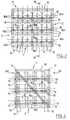
- FIGS. 1 and 2show a rack of the prior art. he has a general shape of a parallelepiped and has several rows of compartments 1 juxtaposed, which are intended to receive the cylinders 2.
- Each bin 1is notably defined by two bars 3 horizontal parallels, the spacing of which is slightly less than diameter of a cylinder 2 and whose length is substantially equal to that of one or more bottles 2.
- We store a bottle 2by the sliding longitudinally between two bars 3 of the same locker 1, the cylinder 2 supported by its sides on these bars 3.
- support bars 3are welded to uprights 4 vertical which extend between the compartments 1, in the height of the rack.
- the support crosspiecesare arranged so that the articles presented come into contact with each other and of each of them.
- the sleepershave essentially a role guiding products to the customer.
- the productsare guided in sliding towards blocking elements at the front of the display, which partially bear the weight of the products.
- the proposed sleepersare moreover made up of metal sheets shaped according to a profile fairly complex in shape in order to improve guidance.
- the sleepersare also hardly used mechanically by the products presented, which are of negligible weight (at most cans, or standard bottles).
- Such a display structuredoes not meet the expectations of professionals in the storage and transport of heavy products such as cylinders for collective fountains.
- An object of the inventionis to propose a rack or chassis for storage for liquid bottles, and more particularly for water tanks, which is more compact and better stability, which is light in weight and inexpensive to manufacture.
- a chassis for the storage of liquid bottles of dimensions and weight similar to those of a water fountain cylinderincluding at least one row of parallel and substantially horizontal bars spaced from each other so as to define two by two of the lockers in which the cylinders are intended to support by their sides on said bars, characterized in that at least two compartments successive have a common grab bar.
- Such a chassis structureis advantageously supplemented by the fact that the distance between said common grab bar and the two bars support on either side of it is equal to or slightly greater than diameter of a cylinder.
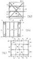
- the storage rack in Figures 3 to 6is carried by four feet 10 and presents an external armature of generally parallelepiped shape, which defines for the rack a bottom F, an upper part S, a front part AV, a rear part AR and two sides C.
- front and rearmust be understood in relation to the direction of introduction of the cylinders into the rack, the "front” part being the part through which a cylinder is introduced.
- terms “lower”, “upper”, “horizontal”, “vertical”should be understood relative to the normal position of the rack, i.e. relative to the position he takes when his feet are on a horizontal plane.
- the rackhas two vertical beams 11, as well as four parallel horizontal beams 12 which each extend between one and the other of the two vertical beams 11.
- One of these beams 12 horizontalextends at the bottom of the rack, another extending at the level of its upper part, the other two being arranged respectively one third and two thirds of the structure supported by feet.
- the rackhas two vertical beams 13, as well as two parallel horizontal beams 14. These horizontal beams 14 extend between the two vertical beams 13, being arranged one at level at the bottom of the rack, the other at its top.
- the rackalso has three horizontal rear crosspieces 15 parallel to the side rails and distributed in the height of said rack. The spacing between two 15 successive sleepers is the same as the spacing between two front side members 12 successive.
- the lower cross member 15is disposed at the near the bottom of the rack and is slightly offset upwards by compared to this one.
- the rackhas three rows of grab bars 16a, 16b which are intended to support the cylinders and which extend between its front part and its rear part.
- each rowhas five grab bars 16a, 16b, including two side bars 16a which extend along the sides of the rack and three center bars 16b.
- the depth of grab bars 16a, 16bis twice the height of a cylinder B.
- the central bars 16bextend between the rear crosspieces 15 and the front side members 12.
- the central bars 16b of the rowlower extend between the rear rear cross member 15 and the side member front 12 which is located at the bottom of the rack.
- the central bars of two other rowsextend in the same way between the crosspieces rear center rails and front center rails.
- Each central bar 16bis a hollow bar consisting of a cylindrical tubular profile which extends straight over a major part of its length and which ends, at its end in the vicinity of the front spar 12 on which it is supported, by a portion 17 which is inclined relative to the rest of said bar.
- the inclined portions 17 of central bars 16bdefine ramps at the front of the rack intended for facilitate the introduction of cylinders.
- the lateral support bars 16aare also hollow bars cylindrical tubulars. They extend straight across their length and are parallel to the main parts of the central bars 16b. These side bars 16a project slightly towards the inside of the rack relative to the vertical beams 11 and 13 which carry them.
- the side bars 16a and the main parts of the central bars 16bare slightly sloping with respect to the horizontal. From the front to the rear of the rack, they have a slight tilting down which helps stabilize the cylinders when they are in place in the rack.
- the distance between two bars 16a, 16b successive of the same rowis equal to the external diameter of a cylinder (or more exactly slightly higher than this of so as to allow a slight play between the cylinders when they are on the rack).
- the bars 16a, 16bare chosen with a cross section sufficient important to allow this support and not to deform under the weight canisters B.
- each central bar 16bis common to two lockers of the same row: it is intended to serve support for the B cylinders slid on one side and the other of said bar 16b.
- the number of grab barsis therefore lower than in the device illustrated in FIGS. 1 and 2.
- the B cylinders juxtaposed in the same row of the rackare just flush with each other to the others, so that the space between two successive B cylinders is minimized.
- the bars 16a and 16bare provided with sheaths, by PVC example, which facilitate the sliding of the cylinders along of said bars.
- these sheathsare advantageously riveted on the rear crosspieces 15, instead to be welded to them.
- the fixing by riveting of the bars 16a and 16b on the rear sleepers 15is made possible by the fact that said bars 16a and 16b extend straight at their rear ends, unlike the prior art devices described with reference in Figures 1 and 2, the grab bars of which are bent at their ends rear towards a vertical mounting post on which they are welded.
- the rivetscan advantageously be used to fix said sheaths on the support bars.
- sheaths on grab barseven if the grab bars are welded on the rear and front parts of the rack frame.
- sheathswhich are open in their length.
- the rackis closed by four longitudinal members 18 (FIGS. 6, 7) which extend between the front and the rear of said rack, by being arranged between two lateral beams 19, which are parallel to the support bars 16a, 16b.
- These four beams 18are offset by half distance between the support bars 16a, 16b and are each located in the middle of a locker defined by two grab bars 16a, 16b successive.
- these longitudinal members 18make it possible to provide some protection for the B cylinders arranged in the upper row of the rack, which otherwise could be exposed to damage.
- the bottom of the rackconsists of rails 18, 19 which are arranged in the same way as those in the upper part.
- the cylindersare thus protected from forklift gripping forks.
- the rack frameOn its sides, the rack frame is defined by the side members vertical side 11, 13 and horizontal 19.
- a post inclined 20, 21extends from one corner to another of the square defined by said horizontal and vertical beams 11, 13 and 19. More specifically, the upright 20 extends between a top front corner and a rear bottom corner of the rack, while the upright 21 extends between a front bottom corner and a top corner back of the rack.
- the rear part of the rackis advantageously reinforced by a cross of Saint Andrew (not shown) which stiffens the frame for allow stacking of the frames on top of each other.
- the beams, crosspieces, bars and uprights of the structure that comes to be describedare made of galvanized steel and are fixed to each other by welding (with the exception, already mentioned, of the rear ends of the bars 16a, 16b which can be riveted on the crosspieces 15).
- front side members 12which extend along the sides of the rack can be used by an operator handling the cylinders like ladder bars on which it can take support to reach for example the upper racks of the rack. So is even for bars 16a.
- a toolconsisting of a hollow tube that can be fitted onto the neck of the carboys.
- This hollow tubeis integral with a structure which carries rollers guide which are distributed on either side of said tube and which are intended to bear slidingly on the bars 16a, 16b.
- This toolis further provided in its front part with a lower support intended to be engaged under the cylinders for support.
- Such a toolis used in the following manner. We slide it in a locker, by resting on the bars 16a and / or 16b thereof. The front of its tube is pressed onto the neck of the cylinder. The tube is then used as a lever for, with the lower holding element, lifting the cylinder by pressing the tube down. We disengage the cylinder in relation to the bars and we bring the cylinder forward by making it slide on the rollers. When the rollers arrive at the portion level inclined 17, the cylinder is placed on these portions 17. It is then in a position that allows him to lift it easily.
- tools of this typecan for example be mounted in parallel on the fork of an elevator to allow to fetch simultaneously several cylinders arranged in different compartments of a same floor.
- the rackis provided with an electronic label, in the form of a memory transponder which contains a code identification of the rack and which makes it possible to trace the cylinders before their delivery.
- the rack described hereis intended for water bottles for fountains collective. However, a rack of the same kind can be used for other bottles such as wine bottles.
- a rack of the same kindcan be used for other bottles such as wine bottles.
- Such a rackis particularly suitable for transporting such products heavy despite the particularly high dynamic constraints which then appear.
Landscapes
- Engineering & Computer Science (AREA)
- Mechanical Engineering (AREA)
- Pallets (AREA)
- Warehouses Or Storage Devices (AREA)
Abstract
Translated fromFrenchDescription
Translated fromFrenchLa présente invention concorne les châssis de stockage pourbonbonnes de liquide ayant un poids et des dimensions similaires à ceuxdes bonbonnes à eau pour fontaines collectives.The present invention relates to storage frames forliquid bottles having a weight and dimensions similar to thosewater bottles for collective fountains.
De tels châssis, également appelés racks par l'homme du métier,sont utilisés pour le rangement et le stockage de bonbonnes d'eaudestinées à des fontaines disposées par exemple dans des lieux publics,des bureaux, etc.. Ces châssis sont notamment destinés à être chargésdans des camions pour permettre la livraison des bonbonnes.Such chassis, also called racks by a person skilled in the art,are used for storing and storing water bottlesintended for fountains arranged for example in public places,offices, etc. These chassis are especially intended to be loadedin trucks to allow delivery of cylinders.
Comme on l'aura compris, ces racks doivent pouvoir êtrechargés ou déchargés aisément en bonbonnes tout en fournissant unmaintien stable, notamment vis-à-vis d'éventuelles secousses, et enprésentant une rigidité suffisante pour pouvoir par exemple être empilés lesuns sur les autres. Lorsqu'ils sont placés dans un camion, ils doiventpermettre à un livreur d'extraire ou d'engager facilement une bonbonne.As will be understood, these racks must be able to beeasily loaded or unloaded in cylinders while providingstable holding, in particular with regard to possible tremors, and inhaving sufficient rigidity to be able for example to be stackedon each other. When placed in a truck, they mustallow a delivery person to easily extract or engage a cylinder.
On a représenté aux figures 1 et 2 un rack de l'art antérieur. Ilprésente une forme générale de parallélépipède et comporte plusieursrangées de casiers 1 juxtaposés, qui sont destinés à recevoir lesbonbonnes 2. Chaque casier 1 est notamment défini par deux barreaux 3parallèles horizontaux, dont l'écartement est légèrement inférieur audiamètre d'une bonbonne 2 et dont la longueur est sensiblement égale àcelle d'une ou plusieurs bonbonnes 2. On range une bonbonne 2 en lafaisant glisser longitudinalement entre deux barreaux 3 d'un même casier 1,la bonbonne 2 prenant appui par ses flancs sur ces barreaux 3.FIGS. 1 and 2 show a rack of the prior art. hehas a general shape of a parallelepiped and has severalrows of
Ces barreaux d'appui 3 sont soudés sur des montants 4verticaux qui s'étendent entre les casiers 1, dans la hauteur du rack.These
Toutefois, un tel châssis - qui est principalement utilisé enAmérique du Nord - s'avère être d'un encombrement important, ainsi qued'un poids peu satisfaisant. Il s'avère également d'une réalisation coûteuse.However, such a chassis - which is mainly used inNorth America - turns out to be very crowded, as well asof an unsatisfactory weight. It also turns out to be an expensive achievement.
On a également proposé, dans le document US 2 649 207, unprésentoir composé lui aussi d'une série de traverses d'appui.It has also been proposed, in document US 2,649,207, adisplay also composed of a series of support crosspieces.
Dans le cas de ce présentoir, les traverses d'appui sontdisposées pour que les articles présentés viennent au contact de part etd'autre de chacune d'entre-elles.In the case of this display, the support crosspieces arearranged so that the articles presented come into contact with each other andof each of them.
Dans un tel présentoir, les traverses ont essentiellement un rôlede guidage des produits vers le client. Les produits sont guidés englissement vers des éléments de blocage à l'avant du présentoir, quiportent en partie le poids des produits. Les traverses proposées sontd'ailleurs constituées de feuilles métalliques mises en forme selon un profiléde forme assez complexe dans le but d'améliorer le guidage.In such a display, the sleepers have essentially a roleguiding products to the customer. The products are guided insliding towards blocking elements at the front of the display, whichpartially bear the weight of the products. The proposed sleepers aremoreover made up of metal sheets shaped according to a profilefairly complex in shape in order to improve guidance.
Les traverses ne sont en outre quasiment pas sollicitéesmécaniquement par les produits présentés, qui sont de poids négligeable(tout au plus des boítes de conserve, ou des bouteilles standard).The sleepers are also hardly usedmechanically by the products presented, which are of negligible weight(at most cans, or standard bottles).
Une telle structure de présentoir ne répond pas aux attentes desprofessionnels du stockage et du transport de produits lourds comme desbonbonnes pour fontaines collectives.Such a display structure does not meet the expectations ofprofessionals in the storage and transport of heavy products such ascylinders for collective fountains.
Un but de l'invention est de proposer un rack ou châssis destockage pour bonbonnes de liquide, et plus particulièrement pourbonbonnes à eau, qui est d'une plus grande compacité et d'une meilleurestabilité, qui est d'un faible poids et dont la fabrication est peu onéreuse.An object of the invention is to propose a rack or chassis forstorage for liquid bottles, and more particularly forwater tanks, which is more compact and betterstability, which is light in weight and inexpensive to manufacture.
Ce but est atteint selon l'invention grâce à un châssis pour lestockage de bonbonnes de liquide ayant des dimensions et un poidssimilaires à ceux d'une bonbonne pour fontaine à eau, comprenant aumoins une rangée de barres parallèles et sensiblement horizontalesespacées les unes des autres de façon à définir deux par deux des casiersdans lesquels les bonbonnes sont destinées à venir en appui par leursflancs sur lesdites barres, caractérisé en ce qu'au moins deux casierssuccessifs comportent une barre d'appui commune.This object is achieved according to the invention thanks to a chassis for thestorage of liquid bottles of dimensions and weightsimilar to those of a water fountain cylinder, includingat least one row of parallel and substantially horizontal barsspaced from each other so as to define two by two of the lockersin which the cylinders are intended to support by theirsides on said bars, characterized in that at least two compartmentssuccessive have a common grab bar.
Une telle structure de châssis est avantageusement complétée parle fait que l'entraxe entre ladite barre d'appui commune et les deux barresd'appui de part et d'autre de celle-ci est égal ou légèrement supérieur audiamètre d'une bonbonne.Such a chassis structure is advantageously supplemented bythe fact that the distance between said common grab bar and the two barssupport on either side of it is equal to or slightly greater thandiameter of a cylinder.
Comme on l'aura compris, le fait d'utiliser une barre d'appuicommune pour deux casiers successifs permet un gain de matièreimportant et simplifie la réalisation du châssis.As will be understood, the fact of using a grab barcommon for two successive lockers saves materialimportant and simplifies the construction of the chassis.
En outre, l'utilisation d'un entraxe entre la barre d'appui égal oulégèrement supérieur au diamètre des bonbonnes permet d'optimiserl'encombrement en largeur du châssis.In addition, the use of a center distance between the equal grab bar orslightly larger than the diameter of the bottles optimizesthe overall width of the chassis.
Par rapport au châssis représenté sur les figures 1 et 2, on gagneen encombrement le volume entre les barres d'appui de deux casierssuccessifs, qui était notamment nécessaire pour loger les montantsverticaux.Compared to the chassis shown in Figures 1 and 2, we gainin bulk the volume between the grab bars of two compartmentssuccessive, which was notably necessary to accommodate the amountsvertical.
D'autres caractéristiques, buts et avantages de la présenteinvention apparaítront à la lecture de la description détaillée qui va suivre,faite en référence aux figures annexées sur lesquelles:
- la figure 1 est une vue de face d'un rack pour bonbonnes à eauconforme à un état de la technique connu;
- la figure 2 est une vue de côté du même rack;
- la figure 3 est une vue de face d'un rack conforme à un modede réalisation possible de l'invention, représenté avec ses bonbonnesd'eau;
- la figure 4 est une vue en coupe selon la ligne IV-IV de la figure3;
- la figure 5 est une vue de côté du même rack, à l'état vide;
- la figure 6 est une vue de dessus du même rack, à l'état vide;
- la figure 7 est une vue en coupe selon la ligne VII-VII de lafigure 3.
- Figure 1 is a front view of a rack for water bottles according to a known state of the art;
- Figure 2 is a side view of the same rack;
- Figure 3 is a front view of a rack according to a possible embodiment of the invention, shown with its water bottles;
- Figure 4 is a sectional view along line IV-IV of Figure 3;
- Figure 5 is a side view of the same rack, in an empty state;
- Figure 6 is a top view of the same rack, in an empty state;
- Figure 7 is a sectional view along line VII-VII of Figure 3.
Le rack de stockage des figures 3 à 6 est porté par quatre pieds 10et présente une armature externe de forme générale parallélépipèdique, quidéfinit pour le rack un fond F, une partie supérieure S, une partie avant AV,une partie arrière AR et deux côtés C.The storage rack in Figures 3 to 6 is carried by four
Dans tout le présent texte, les termes "avant" et "arrière" doivent êtrecompris par rapport au sens d'introduction des bonbonnes dans le rack, lapartie "avant' étant la partie par laquelle on introduit une bonbonne. Lestermes "inférieur', "supérieur', "horizontal", "vertical" doivent être compris par rapport à la position normale du rack, c'est à dire par rapport à laposition qu'il prend lorsque ses pieds portent sur un plan horizontal.Throughout this text, the terms "front" and "rear" must beunderstood in relation to the direction of introduction of the cylinders into the rack, the"front" part being the part through which a cylinder is introduced.terms "lower", "upper", "horizontal", "vertical" should be understoodrelative to the normal position of the rack, i.e. relative to theposition he takes when his feet are on a horizontal plane.
A l'avant, le rack comporte deux longerons verticaux 11, ainsi quequatre longerons 12 horizontaux parallèles qui s'étendent chacun entre l'unet l'autre des deux longerons verticaux 11. L'un de ces longerons 12horizontaux s'étend au niveau du fond du rack, un autre s'étendant auniveau de sa partie supérieure, les deux autres étant disposésrespectivement au tiers et aux deux tiers de la structure portée par lespieds.At the front, the rack has two
A l'arrière, le rack comporte deux longerons verticaux 13, ainsi quedeux longerons horizontaux parallèles 14. Ces longerons horizontaux 14s'étendent entre les deux longerons verticaux 13 en étant disposés l'un auniveau du fond du rack, l'autre au niveau de sa partie supérieure. Le rackprésente également trois traverses arrière horizontales 15 parallèles auxlongerons et réparties dans la hauteur dudit rack. L'espacement entre deuxtraverses 15 successives est identique à l'espacement entre deuxlongerons avant 12 successifs. La traverse 15 inférieure est disposée auvoisinage du fond du rack et est légèrement décalée vers le haut parrapport à celui-ci.At the rear, the rack has two
En son intérieur, le rack présente trois rangées de barres d'appui16a, 16b qui sont destinées à supporter les bonbonnes et qui s'étendententre sa partie avant et sa partie arrière.Inside, the rack has three rows of
Dans l'exemple représenté sur les figures, chaque rangée comportecinq barres d'appui 16a, 16b, dont deux barres latérales 16a qui s'étendentle long des côtés du rack et trois barres centrales 16b. La profondeur desbarres d'appui 16a, 16b est égale à deux fois la hauteur d'une bonbonne B.In the example shown in the figures, each row hasfive
Les barres centrales 16b s'étendent entre les traverses arrière 15 etles longerons avant 12. Notamment, les barres centrales 16b de la rangéeinférieure s'étendent entre la traverse arrière 15 inférieure et le longeronavant 12 qui est situé au niveau du fond du rack. Les barres centrales desdeux autres rangées s'étendent de la même façon entre les traversesmédianes arrière et les longerons médians avant.The
Chaque barre centrale 16b est une barre creuse consistant en unprofilé tubulaire cylindrique qui s'étend de façon droite sur une majeurepartie de sa longueur et qui se termine, à son extrémité au voisinage dulongeron avant 12 sur lequel elle prend appui, par une portion 17 qui estinclinée par rapport au reste de ladite barre. Les portions inclinées 17 desbarres centrales 16b définissent à l'avant du rack des rampes destinées àfaciliter l'introduction des bonbonnes.Each
Les barres d'appui latérales 16a sont également des barres creusestubulaires cylindriques. Elles s'étendent de façon droite sur toute leurlongueur et sont parallèles aux parties principales des barres centrales 16b.Ces barres latérales 16a sont légèrement en saillie vers l'intérieur du rackpar rapport aux longerons verticaux 11 et 13 qui les portent.The
On notera que les barres latérales 16a et les parties principales desbarres centrales 16b sont légèrement en pente par rapport à l'horizontale.Elles présentent en effet, de l'avant vers l'arrière du rack, une légèreinclinaison vers le bas qui contribue à stabiliser les bonbonnes lorsqu'ellessont en place dans le rack.Note that the
Comme on peut le voir sur la figure 3, l'entraxe entre deux barres16a, 16b successives d'une même rangée est égal au diamètre externed'une bonbonne (ou plus exactement légèrement supérieur à celui-ci defaçon à permettre un léger jeu entre les bonbonnes lorsqu'elles sont sur lerack).As can be seen in Figure 3, the distance between two
Ainsi, une bonbonne B glissée entre deux barres 16a, 16b d'unemême rangée est maintenue dans le rack par appui de ses flancs sur cesdeux barres 16a, 16b.Thus, a cylinder B slid between two
Les barres 16a, 16b sont choisies d'une section suffisammentimportante pour permettre cet appui et ne pas se déformer sous le poidsdes bonbonnes B.The
On notera qu'avec cette disposition, chaque barre centrale 16b estcommune à deux casiers d'une même rangée : elle est destinée à servird'appui pour les bonbonnes B glissées d'un côté et de l'autre de ladite barre16b.It will be noted that with this arrangement, each
Le nombre de barres d'appui est donc plus réduit que dans ledispositif illustré sur les figures 1 et 2.The number of grab bars is therefore lower than in thedevice illustrated in FIGS. 1 and 2.
En outre, avec une telle disposition, les bonbonnes B juxtaposéesdans une même rangée du rack sont juste affleurantes les unes par rapportaux autres, de sorte que l'espace entre deux bonbonnes B successives estminimisé.In addition, with such an arrangement, the B cylinders juxtaposedin the same row of the rack are just flush with each otherto the others, so that the space between two successive B cylinders isminimized.
Par conséquent, l'encombrement du rack en largeur est optimal.Consequently, the overall dimensions of the rack are optimal.
Avantageusement, on munit les barres 16a et 16b de gaines, parexemple en PVC, qui facilitent le glissement des bonbonnes le longdesdites barres.Advantageously, the
Pour permettre d'enfiler ces gaines sur lesdites barres 16a et 16b,celles-ci sont avantageusement rivetées sur les traverses arrière 15, au lieud'être soudées sur celles-ci.To allow threading of these sheaths on said
On notera que la fixation par rivetage des barres 16a et 16b sur lestraverses arrière 15 est rendue possible grâce au fait que lesdites barres16a et 16b s'étendent de façon droite à leur extrémité arrières,contrairement aux dispositifs de l'état de la technique décrits en référenceaux figures 1 et 2 dont les barres d'appui sont coudées à leur extrémitéarrière en direction d'un montant vertical de fixation sur lequel elles sontsoudées. Les rivets peuvent avantageusement être utilisés pour fixerlesdites gaines sur les barres d'appui.It will be noted that the fixing by riveting of the
Bien entendu, on peut également prévoir de disposer des gaines surles barres d'appui même dans le cas où les barres d'appui sont soudéessur les parties arrière et avant de l'armature du rack. On utilise par exempleà cet effet des gaines qui sont ouvertes dans leur longueur.Of course, one can also plan to have sheaths ongrab bars even if the grab bars are weldedon the rear and front parts of the rack frame. We use for examplefor this purpose sheaths which are open in their length.
Le nombre de barres d'appui du rack selon l'invention étant réduitpar rapport au nombre de barres d'appui des racks de l'état de la technique,le nombre de gaines s'en trouve également réduit. Ainsi, on utilise iciseulement quinze gaines contre vingt-quatre pour le rack représenté à lafigure 1.The number of rack grab bars according to the invention being reducedcompared to the number of support bars of the racks of the prior art,the number of sheaths is also reduced. So, we use hereonly fifteen sheaths against twenty-four for the rack shown infigure 1.
Par ailleurs, en sa partie supérieure, le rack est fermé par quatrelongerons 18 (figures 6, 7) qui s'étendent entre l'avant et l'arrière dudit rack,en étant disposés entre deux longerons latéraux 19, et qui sont parallèles aux barres d'appui 16a, 16b. Ces quatre longerons 18 sont décalés d'undemi entraxe par rapport aux barres d'appui 16a, 16b et se trouvent chacunau droit du milieu d'un casier défini par deux barres d'appui 16a, 16bsuccessives.In addition, in its upper part, the rack is closed by fourlongitudinal members 18 (FIGS. 6, 7) which extend between the front and the rear of said rack,by being arranged between two
Ainsi, outre qu'ils contribuent à rigidifier l'armature du rack, ceslongerons 18 permettent de réaliser une certaine protection pour lesbonbonnes B disposées dans la rangée supérieure du rack, qui sinonpourraient être exposées à des détériorations.Thus, in addition to helping to stiffen the rack frame, these
Le fond du rack est constitué de longerons 18, 19 qui sont disposésde la même façon que ceux de la partie supérieure. Les bonbonnes sontainsi protégées des fourches de préhension de chariots élévateurs.The bottom of the rack consists of
Sur ses côtés, l'armature du rack est définie par les longeronslatéraux verticaux 11, 13 et horizontaux 19. De chaque côté, un montantincliné 20, 21 s'étend d'un coin à un autre du carré défini par lesditslongerons horizontaux et verticaux 11, 13 et 19. Plus précisément, lemontant 20 s'étend entre un coin haut avant et un coin bas arrière du rack,tandis que le montant 21 s'étend entre un coin bas avant et un coin hautarrière du rack.On its sides, the rack frame is defined by the side members
En outre, la partie arrière du rack est avantageusement renforcéepar une croix de Saint André (non représentée) qui rigidifie le châssis pourpermettre un empilage des châssis les uns sur les autres.In addition, the rear part of the rack is advantageously reinforcedby a cross of Saint Andrew (not shown) which stiffens the frame forallow stacking of the frames on top of each other.
Les longerons, traverses, barres et montants de la structure qui vientd'être décrite sont en acier galvanisé et sont fixés les uns sur les autres parsoudure (à l'exception, déjà évoquée, des extrémités arrière des barres16a, 16b qui peuvent être rivetées sur les traverses 15).The beams, crosspieces, bars and uprights of the structure that comesto be described are made of galvanized steel and are fixed to each other bywelding (with the exception, already mentioned, of the rear ends of the
On notera que les longerons avant 12 qui s'étendent le long descôtés du rack peuvent être utilisés par un opérateur manipulant lesbonbonnes comme des barreaux d'échelle sur lesquels il peut prendreappui pour atteindre par exemple les casiers supérieurs du rack. Il en est demême pour les barres 16a.It will be noted that the
Par ailleurs, pour retirer du rack une bonbonne rangée au fond decelui-ci, c'est à dire vers sa partie arrière, on utilise avantageusement unoutil constitué d'un tube creux qu'il est possible d'emboíter sur le goulot des bonbonnes. Ce tube creux est solidaire d'une structure qui porte des galetsde guidage qui sont répartis de part et d'autre dudit tube et qui sontdestinés à prendre appui en coulissement sur les barres 16a, 16b.In addition, to remove from the rack a cylinder stored at the bottom ofthis one, that is to say towards its rear part, advantageously atool consisting of a hollow tube that can be fitted onto the neck of thecarboys. This hollow tube is integral with a structure which carries rollersguide which are distributed on either side of said tube and which areintended to bear slidingly on the
Cet outil est en outre muni en sa partie avant d'un élément demaintien inférieur destiné à être engagé sous les bonbonnes pour lessoutenir.This tool is further provided in its front part with alower support intended to be engaged under the cylinders forsupport.
Un tel outil s'utilise de la façon suivante. On le fait coulisser dans uncasier, en prenant appui sur les barres 16a et/ou 16b de celui-ci. L'avant deson tube est enfoncé sur le goulot de la bonbonne. Le tube est alors utilisécomme levier pour, avec l'élément de maintien inférieur, soulever labonbonne en appuyant sur le tube vers le bas. On désengage la bonbonnepar rapport aux barres et on ramène la bonbonne vers l'avant en la faisantcoulisser sur les galets. Lorsque les galets arrivent au niveau des portionsinclinées 17, on pose la bonbonne sur ces portions 17. Elle se trouve alorsdans une position qui lui permet de la soulever aisément.Such a tool is used in the following manner. We slide it in alocker, by resting on the
Plusieurs outils de ce type peuvent par exemple être montés enparallèle sur la fourche d'un élévateur pour permettre d'aller cherchersimultanément plusieurs bonbonnes disposées dans différents casiers d'unmême étage.Several tools of this type can for example be mounted inparallel on the fork of an elevator to allow to fetchsimultaneously several cylinders arranged in different compartments of asame floor.
Avantageusement, le rack est muni d'une étiquette électronique,sous forme d'un transpondeur à mémoire qui contient un coded'identification du rack et qui permet de tracer les bonbonnes avant leurlivraison.Advantageously, the rack is provided with an electronic label,in the form of a memory transponder which contains a codeidentification of the rack and which makes it possible to trace the cylinders before theirdelivery.
Le rack décrit ici est destiné à des bonbonnes à eau pour fontainescollectives. Toutefois un rack de même nature peut être utilisé pour d'autresbonbonnes telles que des bonbonnes de vin. On utilise plus généralementles avantages principaux d'un tel rack pour le stockage et le transport debonbonnes ayant des tailles et des poids similaires à ceux des bonbonnesà eau ( typiquement une trentaine de centimètres de diamètre, unecinquantaine de centimètres de haut, et un poids d'environ vingt kilos).The rack described here is intended for water bottles for fountainscollective. However, a rack of the same kind can be used for otherbottles such as wine bottles. We generally usethe main advantages of such a rack for the storage and transport ofcylinders with sizes and weights similar to those of cylinderswater (typically about thirty centimeters in diameter, afifty centimeters high, and a weight of about twenty kilos).
Un tel rack convient notamment pour le transport de tels produitslourds malgré les contraintes dynamiques particulièrement élevées quiapparaissent alors.Such a rack is particularly suitable for transporting such productsheavy despite the particularly high dynamic constraints whichthen appear.
Claims (14)
Translated fromFrenchPriority Applications (1)
| Application Number | Priority Date | Filing Date | Title |
|---|---|---|---|
| US10/203,500US20030091754A1 (en) | 2000-02-11 | 2001-01-19 | Method for treating cellulosic fibres |
Applications Claiming Priority (2)
| Application Number | Priority Date | Filing Date | Title |
|---|---|---|---|
| FR9901749 | 1999-02-12 | ||
| FR9901749AFR2789661B1 (en) | 1999-02-12 | 1999-02-12 | STORAGE CHASSIS FOR LIQUID TANKS AND ESPECIALLY FOR WATER TANKS |
Publications (1)
| Publication Number | Publication Date |
|---|---|
| EP1028073A1true EP1028073A1 (en) | 2000-08-16 |
Family
ID=9541982
Family Applications (1)
| Application Number | Title | Priority Date | Filing Date |
|---|---|---|---|
| EP00400401AWithdrawnEP1028073A1 (en) | 1999-02-12 | 2000-02-11 | Storage rack for liquid carboys, especially water carboys |
Country Status (2)
| Country | Link |
|---|---|
| EP (1) | EP1028073A1 (en) |
| FR (1) | FR2789661B1 (en) |
Cited By (3)
| Publication number | Priority date | Publication date | Assignee | Title |
|---|---|---|---|---|
| EP1190963A1 (en)* | 2000-09-22 | 2002-03-27 | Tonnellerie Baron | Frame for supporting containers with cylindrical symmetry |
| CN109665483A (en)* | 2017-10-16 | 2019-04-23 | 马凯娟 | A kind of the quilt filler and its manufacture craft of natural affine human body |
| CN112320067A (en)* | 2020-09-23 | 2021-02-05 | 郎溪县欧阳泉水厂 | Barreled water placing frame |
Families Citing this family (2)
| Publication number | Priority date | Publication date | Assignee | Title |
|---|---|---|---|---|
| CN110916378A (en)* | 2019-12-06 | 2020-03-27 | 厦门大学 | Device convenient for storing computer equipment |
| CN111960096A (en)* | 2020-07-30 | 2020-11-20 | 安徽凌坤智能科技有限公司 | A snatch system fast for cotton sliver can |
Citations (3)
| Publication number | Priority date | Publication date | Assignee | Title |
|---|---|---|---|---|
| US2649207A (en)* | 1949-05-07 | 1953-08-18 | Grand Union Company | Display and delivery device |
| US3900112A (en)* | 1973-04-09 | 1975-08-19 | Kingston Warren Corp | Gravity storage system |
| FR2581693A1 (en)* | 1985-05-10 | 1986-11-14 | Gaz Ste Lyonnaise | Anti-theft safety device for racks of liquefied-gas bottles |
- 1999
- 1999-02-12FRFR9901749Apatent/FR2789661B1/ennot_activeExpired - Lifetime
- 2000
- 2000-02-11EPEP00400401Apatent/EP1028073A1/ennot_activeWithdrawn
Patent Citations (3)
| Publication number | Priority date | Publication date | Assignee | Title |
|---|---|---|---|---|
| US2649207A (en)* | 1949-05-07 | 1953-08-18 | Grand Union Company | Display and delivery device |
| US3900112A (en)* | 1973-04-09 | 1975-08-19 | Kingston Warren Corp | Gravity storage system |
| FR2581693A1 (en)* | 1985-05-10 | 1986-11-14 | Gaz Ste Lyonnaise | Anti-theft safety device for racks of liquefied-gas bottles |
Cited By (4)
| Publication number | Priority date | Publication date | Assignee | Title |
|---|---|---|---|---|
| EP1190963A1 (en)* | 2000-09-22 | 2002-03-27 | Tonnellerie Baron | Frame for supporting containers with cylindrical symmetry |
| FR2814526A1 (en)* | 2000-09-22 | 2002-03-29 | Tonnellerie Baron | CONSTRUCTION FOR SUPPORTING CONTAINERS OF CYLINDRICAL SYMMETRY |
| CN109665483A (en)* | 2017-10-16 | 2019-04-23 | 马凯娟 | A kind of the quilt filler and its manufacture craft of natural affine human body |
| CN112320067A (en)* | 2020-09-23 | 2021-02-05 | 郎溪县欧阳泉水厂 | Barreled water placing frame |
Also Published As
| Publication number | Publication date |
|---|---|
| FR2789661A1 (en) | 2000-08-18 |
| FR2789661B1 (en) | 2001-05-04 |
Similar Documents
| Publication | Publication Date | Title |
|---|---|---|
| EP0267817A1 (en) | Hand cart | |
| EP1817220B1 (en) | Trolley comprising support means on which two baskets can be stacked | |
| EP0113260B1 (en) | Trolley, in particular for self-service shoppers | |
| EP1028073A1 (en) | Storage rack for liquid carboys, especially water carboys | |
| WO2020169922A1 (en) | Pallet for a barrel in a horizontal position | |
| EP2860134B1 (en) | Container for storing and transporting goods | |
| FR2530570A3 (en) | Nestable self-service trolley with crate holder. | |
| WO2016009009A1 (en) | Pallet collar | |
| BE1013176A3 (en) | Container for transportation of materials rigid sheets. | |
| EP0739805A1 (en) | Shopping cart | |
| FR3021614A1 (en) | TRANSPORT TROLLEY OF STORAGE UNITS AND LOADING-UNLOADING STATION THEREOF | |
| FR2577202A1 (en) | Rack for packaging a batch of objects, particularly heavy and voluminous objects such as bottles of liquefied gas | |
| EP0896935A1 (en) | Device for storing drums | |
| FR3139560A1 (en) | Centering and support interface, and storage rack comprising such an interface. | |
| EP0279999A1 (en) | Crate support for trolleys and trolley with such a support | |
| EP1186384A1 (en) | Mobile toolbox suitable for aerial working | |
| EP4299403A1 (en) | Wagon device for rail transport of goods on pallets | |
| FR2872007A1 (en) | DEVICE AND ASSEMBLY FOR STORING LIQUID CONTAINERS | |
| FR3129118A1 (en) | TRUCK | |
| FR2723559A1 (en) | Trolley for transporting pre-packaged food products, esp. meat | |
| FR2752211A1 (en) | MULTI-PURPOSE TROLLEY OF THE DEVIL TYPE | |
| EP1671890B1 (en) | Container for storing article, having interconnecting corners provided with vertical pillars | |
| FR2860214A1 (en) | Holder for articles such as motor vehicle components comprises base and floor with corner posts and open side, joined together by couplings | |
| FR2856392A1 (en) | OPENING DEVICE AND ASSOCIATED TRANSPORT METHOD | |
| EP1384969A2 (en) | Device for gripping propulsive charge modules |
Legal Events
| Date | Code | Title | Description |
|---|---|---|---|
| PUAI | Public reference made under article 153(3) epc to a published international application that has entered the european phase | Free format text:ORIGINAL CODE: 0009012 | |
| AK | Designated contracting states | Kind code of ref document:A1 Designated state(s):AT BE CH CY DE DK ES FI FR GB GR IE IT LI LU MC NL PT SE | |
| AX | Request for extension of the european patent | Free format text:AL;LT;LV;MK;RO;SI | |
| 17P | Request for examination filed | Effective date:20010207 | |
| AKX | Designation fees paid | Free format text:AT BE CH CY DE DK ES FI FR GB GR IE IT LI LU MC NL PT SE | |
| 17Q | First examination report despatched | Effective date:20030821 | |
| GRAP | Despatch of communication of intention to grant a patent | Free format text:ORIGINAL CODE: EPIDOSNIGR1 | |
| STAA | Information on the status of an ep patent application or granted ep patent | Free format text:STATUS: THE APPLICATION IS DEEMED TO BE WITHDRAWN | |
| 18D | Application deemed to be withdrawn | Effective date:20050628 |