EP1025806B1 - Ultrasonic generator with supervisory control circuitry - Google Patents
Ultrasonic generator with supervisory control circuitryDownload PDFInfo
- Publication number
- EP1025806B1 EP1025806B1EP99300882AEP99300882AEP1025806B1EP 1025806 B1EP1025806 B1EP 1025806B1EP 99300882 AEP99300882 AEP 99300882AEP 99300882 AEP99300882 AEP 99300882AEP 1025806 B1EP1025806 B1EP 1025806B1
- Authority
- EP
- European Patent Office
- Prior art keywords
- output
- circuitry
- frequency
- coupled
- end effector
- Prior art date
- Legal status (The legal status is an assumption and is not a legal conclusion. Google has not performed a legal analysis and makes no representation as to the accuracy of the status listed.)
- Expired - Lifetime
Links
- 239000012636effectorSubstances0.000claimsdescription43
- 230000005540biological transmissionEffects0.000claimsdescription37
- 230000004044responseEffects0.000claimsdescription7
- 238000002955isolationMethods0.000claimsdescription4
- 239000007787solidSubstances0.000claimsdescription4
- 238000010586diagramMethods0.000description12
- 239000000463materialSubstances0.000description12
- 210000001519tissueAnatomy0.000description11
- 238000001514detection methodMethods0.000description7
- 230000007246mechanismEffects0.000description5
- 230000026683transductionEffects0.000description5
- 238000010361transductionMethods0.000description5
- 230000015271coagulationEffects0.000description4
- 238000005345coagulationMethods0.000description4
- 238000000034methodMethods0.000description4
- 229920001296polysiloxanePolymers0.000description4
- 230000000694effectsEffects0.000description3
- 102000004169proteins and genesHuman genes0.000description3
- 108090000623proteins and genesProteins0.000description3
- 230000009467reductionEffects0.000description3
- 229910000838Al alloyInorganic materials0.000description2
- 229910001069Ti alloyInorganic materials0.000description2
- 229910000883Ti6Al4VInorganic materials0.000description2
- 229920004738ULTEM®Polymers0.000description2
- 210000004204blood vesselAnatomy0.000description2
- 230000006835compressionEffects0.000description2
- 238000007906compressionMethods0.000description2
- 238000006073displacement reactionMethods0.000description2
- 238000012986modificationMethods0.000description2
- 230000004048modificationEffects0.000description2
- 230000003534oscillatory effectEffects0.000description2
- 229920003023plasticPolymers0.000description2
- 239000004033plasticSubstances0.000description2
- 239000010935stainless steelSubstances0.000description2
- 229910001220stainless steelInorganic materials0.000description2
- 238000012546transferMethods0.000description2
- 102000008186CollagenHuman genes0.000description1
- 108010035532CollagenProteins0.000description1
- 102000008934Muscle ProteinsHuman genes0.000description1
- 108010074084Muscle ProteinsProteins0.000description1
- 239000004743PolypropyleneSubstances0.000description1
- 229910000831SteelInorganic materials0.000description1
- RTAQQCXQSZGOHL-UHFFFAOYSA-NTitaniumChemical compound[Ti]RTAQQCXQSZGOHL-UHFFFAOYSA-N0.000description1
- 230000002159abnormal effectEffects0.000description1
- 230000003213activating effectEffects0.000description1
- 229910052782aluminiumInorganic materials0.000description1
- XAGFODPZIPBFFR-UHFFFAOYSA-NaluminiumChemical compound[Al]XAGFODPZIPBFFR-UHFFFAOYSA-N0.000description1
- 210000004369bloodAnatomy0.000description1
- 239000008280bloodSubstances0.000description1
- 230000001413cellular effectEffects0.000description1
- 239000000919ceramicSubstances0.000description1
- 230000001112coagulating effectEffects0.000description1
- 229920001436collagenPolymers0.000description1
- 239000013078crystalSubstances0.000description1
- 230000001419dependent effectEffects0.000description1
- NKZSPGSOXYXWQA-UHFFFAOYSA-Ndioxido(oxo)titanium;lead(2+)Chemical compound[Pb+2].[O-][Ti]([O-])=ONKZSPGSOXYXWQA-UHFFFAOYSA-N0.000description1
- 238000004945emulsificationMethods0.000description1
- 230000007613environmental effectEffects0.000description1
- 230000005669field effectEffects0.000description1
- 238000010438heat treatmentMethods0.000description1
- 230000023597hemostasisEffects0.000description1
- 229920005669high impact polystyrenePolymers0.000description1
- 239000004797high-impact polystyreneSubstances0.000description1
- 229910052739hydrogenInorganic materials0.000description1
- 239000001257hydrogenSubstances0.000description1
- 238000003780insertionMethods0.000description1
- 230000037431insertionEffects0.000description1
- HFGPZNIAWCZYJU-UHFFFAOYSA-Nlead zirconate titanateChemical compound[O-2].[O-2].[O-2].[O-2].[O-2].[Ti+4].[Zr+4].[Pb+2]HFGPZNIAWCZYJU-UHFFFAOYSA-N0.000description1
- 229910052451lead zirconate titanateInorganic materials0.000description1
- 239000004973liquid crystal related substanceSubstances0.000description1
- 238000012544monitoring processMethods0.000description1
- 230000001151other effectEffects0.000description1
- -1polypropylenePolymers0.000description1
- 229920001155polypropylenePolymers0.000description1
- 230000008569processEffects0.000description1
- 230000002035prolonged effectEffects0.000description1
- 238000011084recoveryMethods0.000description1
- 230000000087stabilizing effectEffects0.000description1
- 239000010959steelSubstances0.000description1
- 238000004381surface treatmentMethods0.000description1
- 238000001356surgical procedureMethods0.000description1
- 229910052719titaniumInorganic materials0.000description1
- 239000010936titaniumSubstances0.000description1
Images


Classifications
- B—PERFORMING OPERATIONS; TRANSPORTING
- B06—GENERATING OR TRANSMITTING MECHANICAL VIBRATIONS IN GENERAL
- B06B—METHODS OR APPARATUS FOR GENERATING OR TRANSMITTING MECHANICAL VIBRATIONS OF INFRASONIC, SONIC, OR ULTRASONIC FREQUENCY, e.g. FOR PERFORMING MECHANICAL WORK IN GENERAL
- B06B1/00—Methods or apparatus for generating mechanical vibrations of infrasonic, sonic, or ultrasonic frequency
- B06B1/02—Methods or apparatus for generating mechanical vibrations of infrasonic, sonic, or ultrasonic frequency making use of electrical energy
- B06B1/0207—Driving circuits
- B06B1/0223—Driving circuits for generating signals continuous in time
- B06B1/0238—Driving circuits for generating signals continuous in time of a single frequency, e.g. a sine-wave
- B06B1/0246—Driving circuits for generating signals continuous in time of a single frequency, e.g. a sine-wave with a feedback signal
- B06B1/0253—Driving circuits for generating signals continuous in time of a single frequency, e.g. a sine-wave with a feedback signal taken directly from the generator circuit
- A—HUMAN NECESSITIES
- A61—MEDICAL OR VETERINARY SCIENCE; HYGIENE
- A61B—DIAGNOSIS; SURGERY; IDENTIFICATION
- A61B17/00—Surgical instruments, devices or methods
- A61B2017/00017—Electrical control of surgical instruments
- A61B2017/00022—Sensing or detecting at the treatment site
- A61B2017/00106—Sensing or detecting at the treatment site ultrasonic
- A—HUMAN NECESSITIES
- A61—MEDICAL OR VETERINARY SCIENCE; HYGIENE
- A61B—DIAGNOSIS; SURGERY; IDENTIFICATION
- A61B17/00—Surgical instruments, devices or methods
- A61B17/32—Surgical cutting instruments
- A61B17/320068—Surgical cutting instruments using mechanical vibrations, e.g. ultrasonic
- A61B2017/320069—Surgical cutting instruments using mechanical vibrations, e.g. ultrasonic for ablating tissue
- A—HUMAN NECESSITIES
- A61—MEDICAL OR VETERINARY SCIENCE; HYGIENE
- A61B—DIAGNOSIS; SURGERY; IDENTIFICATION
- A61B17/00—Surgical instruments, devices or methods
- A61B17/32—Surgical cutting instruments
- A61B17/320068—Surgical cutting instruments using mechanical vibrations, e.g. ultrasonic
- A61B2017/320089—Surgical cutting instruments using mechanical vibrations, e.g. ultrasonic node location
Definitions
- the inventionpertains to a device for generating ultrasonic signals for use in energizing a transducer assembly at a resonant frequency. More particularly, the invention pertains to an ultrasonic generator which incorporates a phase lock frequency control loop and which further incorporates supervisory circuitry to automatically detect a non-resonant condition and to re-establish resonance.
- Ultrasonic surgical systemswhich can be used for the purpose of carrying out surgical functions, such as cutting or coagulating, are known. Such systems usually incorporate a generator that produces electrical signals which excite a transducer assembly mounted in a handpiece assembly.
- the transducer assemblyis usually coupled to a transmission component, such as an end effector, for carrying out a desired function.
- a transmission componentsuch as an end effector
- the transmission component coupled to the transducer assemblycan be of varying lengths.
- the devices in accordance with the present inventionincrease the performance of ultrasonic surgical systems.
- the devicesare capable of driving longer ultrasonic transmission components and can drive transmission components that have different fundamental frequencies.
- One device in accordance with the present inventionincludes a generator that incorporates a voltage controlled oscillator in combination with a feedback loop which controls the output frequency of the oscillator in a normal operational mode along with a supervisory control circuit.
- the supervisory control circuitis adapted to detect, in one embodiment, an undesired operational mode and, in response thereto, to apply a supervisory and overriding control signal to the oscillator for the purpose of restoring a predetermined phase condition.
- the supervisory control circuitdisconnects or isolates itself from the remaining circuitry thereby enabling the feedback loop to regain control the output of the oscillator.
- a normal operational modewould correspond to operating in a resonant condition.
- An undesired conditionin this instance would be indicated by a loss of resonance.
- the supervisory control circuitryincludes a sensor circuit for detecting an electrical parameter of the feedback signal, such as, for example, phase.
- the sensor circuitis in turn coupled to control circuitry.
- the control circuitryincorporates an enable output and a magnitude output.
- an enable signalis provided by the control unit. This signal in turn couples the magnitude output to a voltage controlled oscillator.
- the magnitude output provided by the supervisory control circuitryin turn supersedes feedback signals from the feedback loop with a supervisory control value or values.
- the superimposed control valuecan be used to re-establish resonance.
- the supervisory control circuitrycan set the magnitude of the output control value to one which corresponds to a feedback signal for the most recent resonant frequency condition. The magnitude of the control value can then be varied to re-establish resonance.
- control circuitryautomatically isolates itself from the feedback control loop which then maintains the output frequency of the oscillator at the resonant value.
- the present inventionmakes it possible to provide electrical signals to and to drive transducers and associated mechanical systems without locking onto undesirable, non-fundamental modes of vibration. Further, acquisition time to establish resonance can be reduced by starting from output control magnitudes corresponding to a known resonant frequency thereby reducing the range of frequencies which must be transversed before a resonant condition is again established.
- control circuitrycan incorporate a digital-to-analog converter which provides analog control signals.
- the digital-to-analog convertercan be used as a form of a programmable frequency generator for the purpose of identifying acoustic systems with unique resonance profiles. Additionally, this circuitry can be used as a sweep generator for valuating acoustic system performance.
- control circuitry, including the digital-to-analog converter circuitrycan be used to provide a form of electronic brake to the associated acoustic system by interrupting resonance when it is necessary to immediately reduce or stop transducer motion.
- FIG. 1illustrates a surgical system 10.
- the surgical system 10generally includes a generator 30, a handpiece assembly 50, and an acoustic or transmission assembly 80.
- the generator 30sends an electrical signal through a cable 32 at a selected amplitude, frequency, and phase determined by a control system of the generator 30.
- the signalcauses one or more piezoelectric elements of the acoustic assembly 80 to expand and contract, thereby converting the electrical energy into mechanical motion.
- the mechanical motionresults in longitudinal waves of ultrasonic energy that propagate through the acoustic assembly 80 in an acoustic standing wave to vibrate the acoustic assembly 80 at a selected frequency and amplitude.
- An end effector 88 at the distal end of the acoustic assembly 80is placed in contact with tissue of the patient to transfer the ultrasonic energy to the tissue.
- the cells of the tissue in contact with the end effector 88 of the acoustic assembly 80will move with the end effector 88 and vibrate.
- the end effector 88couples with the tissue, thermal energy or heat is generated as a result of internal cellular friction within the tissue.
- the heatis sufficient to break protein hydrogen bonds, causing the highly structured protein (i.e., collagen and muscle protein) to denature (i.e., become less organized).
- the proteinsare denatured, a sticky coagulum forms to seal or coagulate small blood vessels when the coagulum is below 100°C. Deep coagulation of larger blood vessels results when the effect is prolonged.
- the transfer of the ultrasonic energy to the tissuecauses other effects including mechanical tearing, cutting, cavitation cell disruption, and emulsification.
- the amount of cutting as well as the degree of coagulation obtainedvaries with the vibrational amplitude of the end effector 88, the amount of pressure applied by the user, and the sharpness of the end effector 88.
- the end effector 88 of the acoustic assembly 80 in the surgical system 10tends to focus the vibrational energy of the system 10 onto tissue in contact with the end effector 88, intensifying and localizing thermal and mechanical energy delivery.
- the generator 30includes a control system integral to the generator 30, a power switch 34, and a triggering mechanism 36.
- the power switch 34controls the electrical power to the generator 30, and when activated by the triggering mechanism 36, the generator 30 provides energy to drive the acoustic assembly 80 of the surgical system 10 at a predetermined frequency and to drive the end effector 88 at a predetermined vibrational amplitude level.
- the generator 30may drive or excite the acoustic assembly 80 at any suitable resonant frequency of the acoustic assembly 80.
- a phase lock loop in the control system of the generator 30monitors feedback from the acoustic assembly 80.
- the phase lock loopadjusts the frequency of the electrical energy sent by the generator 30 to match a preselected harmonic frequency of the acoustic assembly 80.
- a second feedback loop in the control systemmaintains the electrical current supplied to the acoustic assembly 80 at a preselected constant level in order to achieve substantially constant vibrational amplitude at the end effector 88 of the acoustic assembly 80.
- the electrical signal supplied to the acoustic assembly 80will cause the distal end to vibrate longitudinally in the range of, for example, approximately 20 kHz to 100 kHz, and preferably in the range of about 54 kHz to 56 kHz, and most preferably at about 55.5 kHz.
- the amplitude of the acoustic vibrations at the end effector 88may be controlled by, for example, controlling the amplitude of the electrical signal applied to the transducer assembly 82 of the acoustic assembly 80 by the generator 30.
- the triggering mechanism 36 of the generator 30allows a user to activate the generator 30 so that electrical energy may be continuously supplied to the acoustic assembly 80.
- the triggering mechanism 36preferably comprises a foot activating switch that is detachably coupled or attached to the generator 30 by a cable or cord.
- a hand switchmay be incorporated in the handpiece assembly 50 to allow the generator 30 to be activated by a user.
- the generator 30also has a power line 38 for insertion in an electrosurgical unit or conventional electrical outlet. It is contemplated that the generator 30 may also be powered by a direct current (DC) source, such as a battery.
- DCdirect current
- the handpiece assembly 50includes a multi-piece housing or outer casing 52 adapted to isolate the operator from the vibrations of the acoustic assembly 80.
- the housing 52is preferably cylindrically shaped and is adapted to be held by a user in a conventional manner, but may be any suitable shape and size which allows it to be grasped by the user. While a multi-piece housing 52 is illustrated, the housing 52 may comprise a single or unitary component.
- the housing 52 of the handpiece assembly 50is preferably constructed from a durable plastic, such as Ultem®. It is also contemplated that the housing 52 may be made from a variety of materials including other plastics (i.e. high impact polystyrene or polypropylene).
- a suitable handpiece assembly 50is Model No. HP050, available from Ethicon Endo-Surgery, Inc.
- the handpiece assembly 50generally includes a proximal end 54, a distal end 56, and centrally disposed axial opening or cavity 58 extending longitudinally therein.
- the distal end 56 of the handpiece assembly 50includes an opening 60 configured to allow the acoustic assembly 80 of the surgical system 10 to extend therethrough, and the proximal end 54 of the handpiece assembly 50 is coupled to the generator 30 by a cable 32.
- the cable 32may include ducts or vents 62 to allow air to be introduced into the handpiece assembly 50 to cool the transducer assembly 82 of the acoustic assembly 80.
- the acoustic assembly 80generally includes a transducer stack or assembly 82 and a transmission component or working member.
- the transmission componentmay include a mounting device 84, a transmission rod or waveguide 86, and an end effector or applicator 88.
- the transducer assembly 82, mounting device 84, transmission rod 86, and the end effector 88are preferably acoustically tuned such that the length of each component is an integral number of one-half system wavelengths (n ⁇ /2) where the system wavelength ⁇ is the wavelength of a preselected or operating longitudinal vibration frequency f of the acoustic assembly 80.
- the acoustic assembly 80may incorporate any suitable arrangement of acoustic elements.
- the acoustic assembly 80may comprise a transducer assembly and an end effector (i.e., the acoustic assembly 80 may be configured without a mounting device and a transmission rod).
- the transducer assembly 82 of the acoustic assembly 80converts the electrical signal from the generator 30 into mechanical energy that results in longitudinal vibratory motion of the end effector 88 at ultrasonic frequencies.
- a vibratory motion standing waveis generated through the acoustic assembly 80.
- the amplitude of the vibratory motion at any point along the acoustic assembly 80depends on the location along the acoustic assembly 80 at which the vibratory motion is measured.
- a minimum or zero crossing in the vibratory motion standing waveis generally referred to as a node (i.e., where axial motion is usually minimal and radial motion is usually small), and an absolute value maximum or peak in the standing wave is generally referred to as an antinode.
- the distance between an antinode and its nearest nodeis one-quarter wavelength ( ⁇ /4).
- the transducer assembly 82 of the acoustic assembly 80which is known as a "Langevin stack" generally includes a transduction portion 90, a first resonator 92, and a second resonator 94.
- the transducer assembly 82is preferably an integral number of one-half system wavelengths (n ⁇ /2) in length. It is to be understood that the present invention may be alternatively configured to include a transducer assembly comprising a magnetostrictive, electromagnetic or electrostatic transducer.
- the distal end of the first resonator 92is connected to the proximal end of transduction section 90, and the proximal end of the second resonator 94 is connected to the distal end of transduction portion 90.
- the first and second resonators 92 and 94are preferably fabricated from titanium, aluminum, steel, or any other suitable material.
- the first and second resonators 92 and 94have a length determined by a number of variables, including the thickness of the transduction section 90, the density and modulas of elasticity of material used in the resonators 92 and 94, and the fundamental frequency of the transducer assembly 82.
- the second resonator 94may be tapered inwardly from its proximal end to its distal end to amplify the ultrasonic vibration amplitude.
- the transduction portion 90 of the transducer assembly 82preferably comprises a piezoelectric section of alternating positive electrodes 96 and negative electrodes 98, with piezoelectric elements 100 alternating between the electrodes 96 and 98.
- the piezoelectric elements 100may be fabricated from any suitable material, such as, for example, lead zirconate-titanate, lead meta-niobate, lead titanate, or other ceramic crystal material.
- Each of the positive electrodes 96, negative electrodes 98, and piezoelectric elements 100may have a bore extending through the center.
- the positive and negative electrodes 96 and 98are electrically coupled to a wires 102 and 104, respectfully. Wires 102 and 104 transmit electrical signal from the generator 30 to electrodes 96 and 98.
- the piezoelectric elements 100are held in compression between the first and second resonators 92 and 94 by a bolt 106.
- the bolt 106preferably has a head, a shank, and a threaded distal end.
- the bolt 106is inserted from the proximal end of the first resonator 92 through the bores of the first resonator 92, the electrodes 96 and 98, and piezoelectric elements 100.
- the threaded distal end of the bolt 106is screwed into a threaded bore in the proximal end of second resonator 94.
- the piezoelectric elements 100are energized in response to the electrical signal supplied from the generator 30 to produce an acoustic standing wave in the acoustic assembly 80.
- the electrical signalcauses disturbances in the piezoelectric elements 100 in the form of repeated small displacements resulting in large compression forces within the material.
- the repeated small displacementscause the piezoelectric elements 100 to expand and contract in a continuous manner along the axis of the voltage gradient, producing high frequency longitudinal waves of ultrasonic energy.
- the ultrasonic energyis transmitted through the acoustic assembly 80 to the end effector 88.
- the mounting device 84 of the acoustic assembly 80has a proximal end, a distal end, and may have a length substantially equal to an integral number of one-half system wavelengths.
- the proximal end of the mounting device 84is preferably axially aligned and coupled to the distal end of the second resonator 94 by an internal threaded connection near an antinode.
- the term “near”is defined as "exactly at” or "in close proximity to”.
- the mounting device 84may be attached to the second resonator 94 by any suitable means, and that the second resonator 94 and mounting device 84 may be formed as a single or unitary component.
- the mounting device 84is coupled to the housing 52 of the handpiece assembly 50 near a node.
- the mounting device 84may also include an integral ring 108 disposed around its periphery.
- the integral ring 108is preferably disposed in an annular groove 110 formed in the housing 52 of the handpiece assembly 50 to couple the mounting device 84 to the housing 52.
- a compliant member or material 112such as a pair of silicone O-rings attached by stand-offs, may be placed between the annular groove 110 of the housing 52, and the integral ring 108 of the mounting device 84 to reduce or prevent ultrasonic vibration from being transmitted from the mounting device 84 to the housing 52.
- the mounting device 84may be secured in a predetermined axial position by a plurality of pins 114, preferably four.
- the pins 114are disposed in a longitudinal direction 90 degrees apart from each other around the outer periphery of the mounting device 84.
- the pins 114are coupled to the housing 52 of the handpiece assembly 50 and are disposed through notches in the integral ring 108 of the mounting device 84.
- the pins 114are preferably fabricated from stainless steel.
- the mounting device 84is preferably configured to amplify the ultrasonic vibration amplitude that is transmitted through the acoustic assembly 80 to the distal end of the end effector 88.
- the mounting device 84comprises a solid, tapered horn.
- the mounting device 84may be any suitable shape, such as, for example, a stepped horn, a conical horn, an exponential horn, a unitary gain horn or the like.
- the distal end of the mounting device 84may be coupled to the proximal end of the transmission rod 86 by an internal threaded connection. It is contemplated that the transmission rod 86 be attached to the mounting device 84 by any suitable means.
- the mounting device 84is preferably coupled to the transmission rod 86 near an antinode.
- the transmission rod 86may, for example, have a length substantially equal to an integral number of one-half system wavelengths (n ⁇ /2).
- the transmission rod 86is preferably fabricated from a solid core shaft constructed out of material which propagates ultrasonic energy efficiently, such as titanium alloy (i.e., Ti-6Al-4V) or an aluminum alloy. It is contemplated that the transmission rod 86 may be fabricated from any other suitable material.
- the transmission rod 86may also amplify the mechanical vibrations transmitted through the transmission rod 86 to the end effector 88 as is well known in the art.
- the transmission rod 86includes stabilizing silicone rings or compliant supports 116 positioned at a plurality of nodes.
- the silicone rings 116dampen undesirable vibration and isolate the ultrasonic energy from a tubular member of a removable sheath 120 assuring the flow of ultrasonic energy in a longitudinal direction to the distal end of the end effector 88 with maximum efficiency.
- the sheath 120is coupled to the distal end 56 of the handpiece assembly 50.
- the sheath 120generally includes an adapter or nose cone 122 and an elongated tubular member 124.
- the tubular member 124is attached to the adapter 122 and has an opening extending longitudinally therethrough.
- the sheath 120may be threaded or snapped onto the distal end of the housing 52.
- the transmission rod 86 of the acoustic assembly 80extends through the opening of the tubular member 124 and the silicone rings 116 isolate the transmission rod 86 from the tubular member 124.
- the adapter 122 of the sheath 120is preferably constructed from Ultem®, and the tubular member 124 is fabricated from stainless steel. Alternatively, the transmission rod 86 may have polymeric material that surrounds the transmission rod 86 to isolate it from outside contact.
- the distal end of the transmission rod 86may be coupled to the proximal end of the end effector 88 by an internal threaded connection, preferably near an antinode. It is contemplated that the end effector 88 may be attached to the transmission rod 86 by any suitable means, such as a welded joint or the like. Although the end effector 88 may be detachable from the transmission rod 86, it is also contemplated that the end effector 88 and transmission rod 86 may be formed as a single unit.
- the end effector 88may have a distal region 88b having a smaller cross-section area than a proximal region 88a thereof, thereby forming a vibrational amplitude step-up junction.
- the step-up junctionacts as velocity transformer as known in the art, increasing the magnitude of the ultrasonic vibration transmitted from the proximal region 88a to the distal region 88b of the end effector 88.
- the end effector 88preferably has a length substantially equal to an integral multiple of one-half system wavelengths (n ⁇ /2).
- the end effector 88is disposed at an antinode in order to produce the maximum longitudinal deflection of the distal end.
- the distal end of the end effector 88is configured to move longitudinally in the range of, for example, approximately 10 to 500 microns peak-to-peak, and preferably in the range of about 30 to 100 microns at a predetermined vibrational frequency, and most preferably at about 90 microns.
- the end effector 88is preferably made from a solid core shaft constructed of material which propagates ultrasonic energy, such as a titanium alloy (i.e., Ti-6Al-4V) or an aluminum alloy. It is contemplated that the end effector 88 may be fabricated from any other suitable material. It is also contemplated that the end effector 88 may have a surface treatment to improve the delivery of energy and desired tissue effect. For example, the end effector 88 may be micro-finished, coated, plated, etched, grit-blasted, roughened or scored to enhance coagulation in tissue or to reduce adherence of tissue and blood to the end effector. Additionally, the end effector 88 may be sharpened or shaped to enhance its energy transmission characteristics. For example, the end effector 88 may be blade shaped, hook shaped, or ball shaped.
- the block diagram of FIG. 2illustrates an exemplary generator 30 of the surgical system 10.
- the generator 30includes a processor 30-1, such as, for example, a programmed microprocessor which may, for example, be a Motorola model number 68HC11.
- the processor 30-1is programmed to monitor appropriate power parameters and vibratory frequency as well as providing an appropriate power level in various operating modes.
- Manually operable controls 30-2are provided for the purpose of enabling an operator to adjust the power level to be applied to the transducer assembly when operating. Hence, simultaneous cutting and small vessel coagulation of a predetermined level can be obtained whenever the end effector 88 is in contact with tissue.
- the generator 30includes a power output switch 30-3 which is in turn coupled to a matching network 30-4.
- the power switch 30-3supplies electrical energy to the handpiece assembly 50 by way of a matching network 30-4 and an isolation transformer 30-4a.
- Feedback from the handpiece assembly 50, and the transducer assembly therein,is coupled via amplifier 30-5 to a phase detector 30-6.
- Output from the phase detector 30-6is fed to an input port of a voltage controlled oscillator 30-7.
- the voltage controlled oscillator 30-7generates a variable frequency output signal on the line 30-8.
- the signal on the line 30-8can be divided in a divide by a four counter or network 30-9.
- the divided variable frequency signalis then provided on a line 30-10 as an input to the power switch 30-3, previously discussed.
- a delay element 30-11provides a delay signal to the phase detector 30-6.
- a power control unit 30-12is coupled between the processor 30-1 and the power switch 30-3.
- An output liquid crystal display 30-13may also be coupled to the processor 30-1.
- the display 30-13is intended to provide a status information for the user or operator.
- Line 30-15which is coupled to input E2 of the processor 30-1, enables the processor 30-1 to monitor ultrasonic drive current detected at the output of the network 30-4.
- This lineincludes a root means square (RMS) to DC converter 30-15a.
- RMSroot means square
- An oscillator output voltageis sensed at input E3 of the processor 30-1 while an output frequency is sensed at A7 of the processor 30-1.
- Output voltageis sensed at E1 of the processor 30-1.
- Output B0 of the processor 30-1provides an enable signal to the power switch 30-3.
- Frequency control for generating output signals from the generator 30, corresponding to a resonant frequency of the acoustic assembly 80 (carried by the handpiece assembly 50),is produced through the use of a phase lock loop which includes a phase detector 30-6 and oscillator 30-7.
- the phase detector 30-6compares the phase of the output driving current and voltage signals with an error signal obtained from the phase detector used to control the voltage controlled oscillator 30-7 to thereby produce the desired output frequency.
- An output on a line 30-14 (input E3) from the voltage controlled oscillator 30-7is a voltage which is proportional to the generator frequency. It is used for the purpose of monitoring to determine whether or not the frequency is within a proper operating range.
- the actual variable frequency output signal from the oscillator 30-7is coupled on a line 30-8 to the processor 30-1 (input A7).
- FIG. 3illustrates a block diagram of a generator 130 in accordance with the present invention for use with the ultrasonic system 10.
- the generator 130includes phase detection circuitry 132 which is coupled to a voltage controlled oscillator 134.
- Elements 132 and 134can be implemented in a single integrated circuit, such as, for example, a CD4046 circuit which incorporates a phase-lock frequency control loop.
- the divider 138may include a plurality of flip-flop circuits configured as a counter to produce the frequency divider function.
- the divided output signal on a line 140is provided to a power switch 142 and to a delay feedback element 144. Further inputs to the power switch 142 are provided by a processor or supervisory control unit 146 and power control unit 149.
- the control unit 146provides overall control for the generator 130. Output signals from the power switch 142 are coupled by a matching network 148 to an isolation transformer 152.
- the matching network 148converts an output square wave of the power switch 142 into a sine wave for driving the handpiece assembly 50.
- the output of the matching network 148provides feedback signals via the RMS to DC converter 151 to the control unit 146, and via comparator 150 to the phase detection circuitry 132.
- phase detection circuitry 132 and voltage controlled oscillator 134function with established minimum and maximum operating frequencies.
- Output signals from the oscillator 134 in combination with feedback signals from the output of the matching network 148establish a resonant condition at the output acoustic assembly of the handpiece assembly 50.
- control provided by the phase detection circuitry 132 and voltage control oscillator 134may not be sufficient to respond to a changing environment. For example, voltage and frequency changes occur with both heating and variations in the characteristics of ultrasonic components. As a result, minimum and maximum frequencies may vary.
- the generator 130includes a control feedback loop 160.
- the control circuitry 160includes detector circuitry 162 which is coupled to the phase detection circuitry 132.
- the detector circuitry 162senses the presence or absence of a phase locked condition in the phase detection circuitry 132 and voltage controlled oscillator 134.
- An exemplary circuit diagram of the detector circuitry 162is illustrated in FIG. 3A.
- the detector circuitry 162, on a line 164provides an indication of the presence or absence of phase lock to a feedback processor unit 166, such as, for example, a programmable digital processor. It will be understood that a variety of programmable processors could be used to process the signals on the line 164 without departing from the spirit and scope of the present invention.
- the processor unit 166could also be incorporated into the processor 146 (indicated by a line 166a). Alternately, the processor unit 166 could be implemented as a hard wired logic system.
- the processor unit 166has two output ports 168a and 168b.
- the output port 168amay include a plurality of parallel digital data lines (for example 8 or 16 bits) that provide digital input drive signals to a digital to analog converter 170.
- the converter 170sends a voltage signal on a line 172 to an input of an analog switch 174.
- the analog switch 174could be implemented as 333A (MAXIM), for example.
- An exemplary circuit diagram of the converter 170 and analog switch 174is illustrated in FIG. 3A.
- the second output port 168b of the processor unit 166provides a control signal to a control input of the switch 174 for the purpose of causing the switch 174 to exhibit a conducting or a non-conducting state.
- An output of the switch 174, on a line 176,provides an override voltage control signal to the input port of the voltage controlled oscillator 134.
- the override voltage control signal on the line 176overrides the signal from the phase detector 132 and provides an input to the voltage controlled oscillator 134 corresponding to a known desired condition.
- the override control signal on the line 176can be used to establish the last known resonant frequency exhibited by the system 10. Further, the processor unit 166 can sweep the value of the override signal on the line 176, starting from the last known resonant frequency, between minimum and maximum permissible frequency values for the system so as to quickly re-establish a resonant condition.
- analog switch 174assumes an open or non-conducting state, in response to the control signal from the output port 168b. This isolation in turn enables the phase lock loop system, (i.e., elements 132, 134) to resume normal operational control of the acoustic system.
- processor unit 166By incorporating processor unit 166 into the generator 130, tighter control can be maintained over the minimum and maximum permissible frequency values.
- the processor unit 166effectively establishes frequencies in the frequency domain which in turn minimizes voltage variation effects.
- a communications link 166acan be provided between the processor unit 166 and the supervisory control unit 146.
- Such a linkin turn makes it possible for an operator, via the display 150b and inputs 150c to establish minimum and maximum frequencies, hence bandwidth, for the purpose of driving acoustic systems with significantly different fundamental frequencies. This in turn makes it possible to adjust the minimum frequency so as to drive acoustic systems having greater thermal frequency variations.
- the processor unit 166makes it possible to drive the acoustic assembly of the surgical system 10 at a predetermined fixed frequency so as to measure a non-resonant transducer assembly property. These properties would include, for example, impedance characteristics of end effectors 88.
- the generator 130is also capable of providing immediate reductions in longitudinal motion of the acoustical assembly of the surgical system 10 where desired, by altering the voltage input on the line 176 to the voltage controlled oscillator 134.
- the voltage on the line 176can be altered so as to purposely drive the acoustic assembly into a non-resonant condition thereby producing an immediate reduction in motion of the end effector 88.
- Additional advantages provided by the generator 130include reduction of the time necessary to establish a resonant condition due to being able to impose greater control over a minimum and maximum frequency variations. Recovery time to a resonant condition is reduced by being able to retrieve the frequency associated with a recent successful resonant condition from storage. The stored value, representative of resonant frequency, can in turn be used as a starting point for purposes of varying drive frequency to the system while searching for an acceptable resonant condition.
- Output voltage from the digital to analog converter 170can also be used for the purpose of identifying acoustic systems with unique resonance profiles. This can be carried out by driving the converter 170 as a programmable frequency generator. Finally, the same operational characteristics can be used for evaluating the performance of acoustical systems.
- FIGS. 4A and Bare a schematic diagram of various components of the generator 130. As illustrated in FIG. 4A, the phase lock loop system, elements 132, 134 can be implemented by means of a 4046 integrated circuit. Frequency divider circuitry 138 can be implemented as two series coupled D-type flip-flop circuits.
- Power switch control 142incorporates an IR2110 field effect switches Q5, Q6 which in turn are coupled to the matching network 148.
- the network 148incorporates an LC filter for converting pulses from the power switch to a sine wave-like output signal.
- the delay 144as illustrated in FIG. 4A, can be implemented by means of a monostable multivibrator. Feedback is also provided via comparator 150, illustrated in FIG. 4B as an LM339 integrated circuit.
- Input to the lock detection circuitry 162can be obtained from a phase pulse output line, such as pin 1 of the 4046 integrated circuit on line 163.
- Output voltages from the control loop 160, on the line 176can be coupled to the voltage input port, pin 9 of the 4046 integrated circuit.
- Microprocessor 146could be implemented using a Motorola type 68HC11 programmable microprocessor. Other types of microprocessors can be incorporated without departing from the spirit and scope of the present invention.
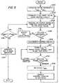
- FIG. 5illustrates a flow diagram of a method of controlling the acoustic assembly of the surgical system so as to detect abnormal operational conditions and return to a resonant condition.
- a transducer frequency range specified by F min and F maxis established and stored.
- supervisory circuitry 160can be used to establish an initial input voltage value for the voltage controlled oscillator 134.
- the oscillator 134produces the desired frequency which is in turn coupled to the acoustic assembly of the surgical system.
- the control circuitry 160determines whether or not the acoustic assembly 50 is being operated in a resonant condition. If so, in a step 208 the control circuitry 160 is decoupled. In a step 210, a representation of the current resonant frequency FRES is stored and the phase lock loop system 132, 134 commences control of the output to the acoustic assembly.
- a step 212the circuitry 160 continues to monitor the presence or absence of a resonant condition. If the phase lock loop system 132, 134 has failed to maintain a resonant condition in a step 214, the most recently stored representation of a resonant frequency FRES can be retrieved from a storage element by the processor unit 166 and then used in step 202 to establish a new input to the voltage controlled oscillator 134 for the purpose of re-establishing resonance. That input can then be swept between the minimum and maximum permissible frequency values if need be to find a new resonant condition.
- the input voltage value to the voltage controlled oscillator 134can be adjusted in a step 216.
- the adjusted valuecan be checked to determine that it is still within the acceptable range between minimum and maximum preset frequency values. If so, it can then can be used to generate a new output frequency in the step 204.
- an error conditioncan be indicated at a step 220.
Landscapes
- Engineering & Computer Science (AREA)
- Mechanical Engineering (AREA)
- Surgical Instruments (AREA)
- Apparatuses For Generation Of Mechanical Vibrations (AREA)
- Oscillators With Electromechanical Resonators (AREA)
- Stabilization Of Oscillater, Synchronisation, Frequency Synthesizers (AREA)
- Transducers For Ultrasonic Waves (AREA)
Description
- The invention pertains to a device for generating ultrasonic signals for use in energizing a transducer assembly at a resonant frequency. More particularly, the invention pertains to an ultrasonic generator which incorporates a phase lock frequency control loop and which further incorporates supervisory circuitry to automatically detect a non-resonant condition and to re-establish resonance.
- Ultrasonic surgical systems which can be used for the purpose of carrying out surgical functions, such as cutting or coagulating, are known. Such systems usually incorporate a generator that produces electrical signals which excite a transducer assembly mounted in a handpiece assembly.
- The transducer assembly is usually coupled to a transmission component, such as an end effector, for carrying out a desired function. The transmission component coupled to the transducer assembly can be of varying lengths.
- As the transmission component is subjected to varying environmental conditions, temperature characteristics may vary with the result that a given generator may function at suboptimal operating conditions. Further, as the length of the transmission component coupled to the transducer is increased, additional undesirable oscillatory nodes may occur along the transmission component.
- There continues to be a need for generators which will function when transmission components are exposed to substantially temperature invariant characteristics over time and will also control undesirable oscillatory motion.
- In US-A-4,275,363, there is disclosed an ultrasonic surgical device of the type set forth in the preamble of the accompanying
claim 1. - In US-A-4,979,952, there is disclosed an ultrasonic surgical device having a detector for detecting the impedance of an oscillating circuit in an ultrasonic vibrator at the time of resonance of the circuit.
- The devices in accordance with the present invention increase the performance of ultrasonic surgical systems. The devices are capable of driving longer ultrasonic transmission components and can drive transmission components that have different fundamental frequencies.
- According to the invention, there is provided an ultrasonic surgical device as set forth in the accompanying
claim 1. - Further preferred aspects are set out in the accompanying dependent claims 2-8.
- One device in accordance with the present invention includes a generator that incorporates a voltage controlled oscillator in combination with a feedback loop which controls the output frequency of the oscillator in a normal operational mode along with a supervisory control circuit. The supervisory control circuit is adapted to detect, in one embodiment, an undesired operational mode and, in response thereto, to apply a supervisory and
overriding control signal to the oscillator for the purpose of restoring a predetermined phase condition. When the normal operational mode has been restored, the supervisory control circuit disconnects or isolates itself from the remaining circuitry thereby enabling the feedback loop to regain control the output of the oscillator. - For example, when the generator is intended to drive an ultrasonic transducer at a resonant frequency, a normal operational mode would correspond to operating in a resonant condition. An undesired condition, in this instance would be indicated by a loss of resonance.
- In one aspect of the present invention, the supervisory control circuitry includes a sensor circuit for detecting an electrical parameter of the feedback signal, such as, for example, phase. The sensor circuit is in turn coupled to control circuitry. The control circuitry incorporates an enable output and a magnitude output.
- In response to sensing a loss of a predetermined phase condition in the oscillator, an enable signal is provided by the control unit. This signal in turn couples the magnitude output to a voltage controlled oscillator. The magnitude output provided by the supervisory control circuitry in turn supersedes feedback signals from the feedback loop with a supervisory control value or values.
- The superimposed control value can be used to re-establish resonance. In one embodiment, the supervisory control circuitry can set the magnitude of the output control value to one which corresponds to a feedback signal for the most recent resonant frequency condition. The magnitude of the control value can then be varied to re-establish resonance.
- Once resonance has been re-established, the control circuitry automatically isolates itself from the feedback control loop which then maintains the output frequency of the oscillator at the resonant value.
- The present invention makes it possible to provide electrical signals to and to drive transducers and associated mechanical systems without locking onto undesirable, non-fundamental modes of vibration. Further, acquisition time to establish resonance can be reduced by starting from output control magnitudes corresponding to a known resonant frequency thereby reducing the range of frequencies which must be transversed before a resonant condition is again established.
- In another aspect, the control circuitry can incorporate a digital-to-analog converter which provides analog control signals. The digital-to-analog converter can be used as a form of a programmable frequency generator for the purpose of identifying acoustic systems with unique resonance profiles. Additionally, this circuitry can be used as a sweep generator for valuating acoustic system performance. Finally, the control circuitry, including the digital-to-analog converter circuitry can be used to provide a form of electronic brake to the associated acoustic system by interrupting resonance when it is necessary to immediately reduce or stop transducer motion.
- Numerous other advantages and features of the present invention will become readily apparent from the following detailed description of the invention and the embodiments thereof, from the claims and from the accompanying drawings.
- FIG. 1 is a fragmentary view and in partial cross-section of an embodiment of an ultrasonic system;
- FIG. 2 is ia block diagram of a generator usable with the system of FIG. 1;
- FIG. 3 is a block diagram of a generator which incorporates supervisory control circuitry;
- FIG. 3A is a schematic diagram of various components of the generator of FIG. 3;
- FIGS. 4A and 4B are a schematic diagram of various components of the generator of FIG. 3; and
- FIG. 5 is a flow diagram of a control method implementable by the generator of FIG. 3.
- While the present invention is susceptible of embodiment in many different forms, there are shown in the drawings and will be described herein in detail specific embodiments thereof with the understanding that the present disclosure is to be considered as an exemplification of the principles of the invention and is not intended to limit the invention to the specific embodiments illustrated.
- FIG. 1 illustrates a
surgical system 10. Thesurgical system 10 generally includes agenerator 30, ahandpiece assembly 50, and an acoustic ortransmission assembly 80. Thegenerator 30 sends an electrical signal through acable 32 at a selected amplitude, frequency, and phase determined by a control system of thegenerator 30. As will be further described, the signal causes one or more piezoelectric elements of theacoustic assembly 80 to expand and contract, thereby converting the electrical energy into mechanical motion. The mechanical motion results in longitudinal waves of ultrasonic energy that propagate through theacoustic assembly 80 in an acoustic standing wave to vibrate theacoustic assembly 80 at a selected frequency and amplitude. - An
end effector 88 at the distal end of theacoustic assembly 80 is placed in contact with tissue of the patient to transfer the ultrasonic energy to the tissue. The cells of the tissue in contact with theend effector 88 of theacoustic assembly 80 will move with theend effector 88 and vibrate. - As the
end effector 88 couples with the tissue, thermal energy or heat is generated as a result of internal cellular friction within the tissue. The heat is sufficient to break protein hydrogen bonds, causing the highly structured protein (i.e., collagen and muscle protein) to denature (i.e., become less organized). As the proteins are denatured, a sticky coagulum forms to seal or coagulate small blood vessels when the coagulum is below 100°C. Deep coagulation of larger blood vessels results when the effect is prolonged. - The transfer of the ultrasonic energy to the tissue causes other effects including mechanical tearing, cutting, cavitation cell disruption, and emulsification. The amount of cutting as well as the degree of coagulation obtained varies with the vibrational amplitude of the
end effector 88, the amount of pressure applied by the user, and the sharpness of theend effector 88. Theend effector 88 of theacoustic assembly 80 in thesurgical system 10 tends to focus the vibrational energy of thesystem 10 onto tissue in contact with theend effector 88, intensifying and localizing thermal and mechanical energy delivery. - As illustrated in FIG. 1, the
generator 30 includes a control system integral to thegenerator 30, apower switch 34, and a triggeringmechanism 36. Thepower switch 34 controls the electrical power to thegenerator 30, and when activated by the triggeringmechanism 36, thegenerator 30 provides energy to drive theacoustic assembly 80 of thesurgical system 10 at a predetermined frequency and to drive theend effector 88 at a predetermined vibrational amplitude level. Thegenerator 30 may drive or excite theacoustic assembly 80 at any suitable resonant frequency of theacoustic assembly 80. - When the
generator 30 is activated via the triggeringmechanism 36, electrical energy is continuously applied by thegenerator 30 to atransducer assembly 82 of theacoustic assembly 80. A phase lock loop in the control system of thegenerator 30 monitors feedback from theacoustic assembly 80. The phase lock loop adjusts the frequency of the electrical energy sent by thegenerator 30 to match a preselected harmonic frequency of theacoustic assembly 80. In addition, a second feedback loop in the control system maintains the electrical current supplied to theacoustic assembly 80 at a preselected constant level in order to achieve substantially constant vibrational amplitude at theend effector 88 of theacoustic assembly 80. - The electrical signal supplied to the
acoustic assembly 80 will cause the distal end to vibrate longitudinally in the range of, for example, approximately 20 kHz to 100 kHz, and preferably in the range of about 54 kHz to 56 kHz, and most preferably at about 55.5 kHz. The amplitude of the acoustic vibrations at theend effector 88 may be controlled by, for example, controlling the amplitude of the electrical signal applied to thetransducer assembly 82 of theacoustic assembly 80 by thegenerator 30. - As noted above, the triggering
mechanism 36 of thegenerator 30 allows a user to activate thegenerator 30 so that electrical energy may be continuously supplied to theacoustic assembly 80. In one embodiment, the triggeringmechanism 36 preferably comprises a foot activating switch that is detachably coupled or attached to thegenerator 30 by a cable or cord. In another embodiment, a hand switch may be incorporated in thehandpiece assembly 50 to allow thegenerator 30 to be activated by a user. - The
generator 30 also has apower line 38 for insertion in an electrosurgical unit or conventional electrical outlet. It is contemplated that thegenerator 30 may also be powered by a direct current (DC) source, such as a battery. - Referring still to FIG. 1, the
handpiece assembly 50 includes a multi-piece housing orouter casing 52 adapted to isolate the operator from the vibrations of theacoustic assembly 80. Thehousing 52 is preferably cylindrically shaped and is adapted to be held by a user in a conventional manner, but may be any suitable shape and size which allows it to be grasped by the user. While amulti-piece housing 52 is illustrated, thehousing 52 may comprise a single or unitary component. - The
housing 52 of thehandpiece assembly 50 is preferably constructed from a durable plastic, such as Ultem®. It is also contemplated that thehousing 52 may be made from a variety of materials including other plastics (i.e. high impact polystyrene or polypropylene). Asuitable handpiece assembly 50 is Model No. HP050, available from Ethicon Endo-Surgery, Inc. - The
handpiece assembly 50 generally includes aproximal end 54, adistal end 56, and centrally disposed axial opening orcavity 58 extending longitudinally therein. Thedistal end 56 of thehandpiece assembly 50 includes anopening 60 configured to allow theacoustic assembly 80 of thesurgical system 10 to extend therethrough, and theproximal end 54 of thehandpiece assembly 50 is coupled to thegenerator 30 by acable 32. Thecable 32 may include ducts or vents 62 to allow air to be introduced into thehandpiece assembly 50 to cool thetransducer assembly 82 of theacoustic assembly 80. - Referring still to FIG. 1, the
acoustic assembly 80 generally includes a transducer stack orassembly 82 and a transmission component or working member. The transmission component may include a mounting device 84, a transmission rod orwaveguide 86, and an end effector orapplicator 88. Thetransducer assembly 82, mounting device 84,transmission rod 86, and theend effector 88 are preferably acoustically tuned such that the length of each component is an integral number of one-half system wavelengths (nλ/2) where the system wavelength λ is the wavelength of a preselected or operating longitudinal vibration frequency f of theacoustic assembly 80. It is also contemplated that theacoustic assembly 80 may incorporate any suitable arrangement of acoustic elements. For example, theacoustic assembly 80 may comprise a transducer assembly and an end effector (i.e., theacoustic assembly 80 may be configured without a mounting device and a transmission rod). - The
transducer assembly 82 of theacoustic assembly 80 converts the electrical signal from thegenerator 30 into mechanical energy that results in longitudinal vibratory motion of theend effector 88 at ultrasonic frequencies. When theacoustic assembly 80 is energized, a vibratory motion standing wave is generated through theacoustic assembly 80. The amplitude of the vibratory motion at any point along theacoustic assembly 80 depends on the location along theacoustic assembly 80 at which the vibratory motion is measured. A minimum or zero crossing in the vibratory motion standing wave is generally referred to as a node (i.e., where axial motion is usually minimal and radial motion is usually small), and an absolute value maximum or peak in the standing wave is generally referred to as an antinode. The distance between an antinode and its nearest node is one-quarter wavelength (λ/4). - As shown in FIG. 1, the
transducer assembly 82 of theacoustic assembly 80, which is known as a "Langevin stack", generally includes atransduction portion 90, afirst resonator 92, and asecond resonator 94. Thetransducer assembly 82 is preferably an integral number of one-half system wavelengths (nλ/2) in length. It is to be understood that the present invention may be alternatively configured to include a transducer assembly comprising a magnetostrictive, electromagnetic or electrostatic transducer. - The distal end of the
first resonator 92 is connected to the proximal end oftransduction section 90, and the proximal end of thesecond resonator 94 is connected to the distal end oftransduction portion 90. The first andsecond resonators second resonators transduction section 90, the density and modulas of elasticity of material used in theresonators transducer assembly 82. Thesecond resonator 94 may be tapered inwardly from its proximal end to its distal end to amplify the ultrasonic vibration amplitude. - The
transduction portion 90 of thetransducer assembly 82 preferably comprises a piezoelectric section of alternatingpositive electrodes 96 andnegative electrodes 98, withpiezoelectric elements 100 alternating between theelectrodes piezoelectric elements 100 may be fabricated from any suitable material, such as, for example, lead zirconate-titanate, lead meta-niobate, lead titanate, or other ceramic crystal material. Each of thepositive electrodes 96,negative electrodes 98, andpiezoelectric elements 100 may have a bore extending through the center. The positive andnegative electrodes wires Wires generator 30 toelectrodes - As illustrated in FIG. 1, the
piezoelectric elements 100 are held in compression between the first andsecond resonators bolt 106. Thebolt 106 preferably has a head, a shank, and a threaded distal end. Thebolt 106 is inserted from the proximal end of thefirst resonator 92 through the bores of thefirst resonator 92, theelectrodes piezoelectric elements 100. The threaded distal end of thebolt 106 is screwed into a threaded bore in the proximal end ofsecond resonator 94. - The
piezoelectric elements 100 are energized in response to the electrical signal supplied from thegenerator 30 to produce an acoustic standing wave in theacoustic assembly 80. The electrical signal causes disturbances in thepiezoelectric elements 100 in the form of repeated small displacements resulting in large compression forces within the material. The repeated small displacements cause thepiezoelectric elements 100 to expand and contract in a continuous manner along the axis of the voltage gradient, producing high frequency longitudinal waves of ultrasonic energy. The ultrasonic energy is transmitted through theacoustic assembly 80 to theend effector 88. - The mounting device 84 of the
acoustic assembly 80 has a proximal end, a distal end, and may have a length substantially equal to an integral number of one-half system wavelengths. The proximal end of the mounting device 84 is preferably axially aligned and coupled to the distal end of thesecond resonator 94 by an internal threaded connection near an antinode. (For purposes of this disclosure, the term "near" is defined as "exactly at" or "in close proximity to".) It is also contemplated that the mounting device 84 may be attached to thesecond resonator 94 by any suitable means, and that thesecond resonator 94 and mounting device 84 may be formed as a single or unitary component. - The mounting device 84 is coupled to the
housing 52 of thehandpiece assembly 50 near a node. The mounting device 84 may also include an integral ring 108 disposed around its periphery. The integral ring 108 is preferably disposed in anannular groove 110 formed in thehousing 52 of thehandpiece assembly 50 to couple the mounting device 84 to thehousing 52. A compliant member or material 112, such as a pair of silicone O-rings attached by stand-offs, may be placed between theannular groove 110 of thehousing 52, and the integral ring 108 of the mounting device 84 to reduce or prevent ultrasonic vibration from being transmitted from the mounting device 84 to thehousing 52. - The mounting device 84 may be secured in a predetermined axial position by a plurality of
pins 114, preferably four. Thepins 114 are disposed in alongitudinal direction 90 degrees apart from each other around the outer periphery of the mounting device 84. Thepins 114 are coupled to thehousing 52 of thehandpiece assembly 50 and are disposed through notches in the integral ring 108 of the mounting device 84. Thepins 114 are preferably fabricated from stainless steel. - The mounting device 84 is preferably configured to amplify the ultrasonic vibration amplitude that is transmitted through the
acoustic assembly 80 to the distal end of theend effector 88. In one preferred embodiment, the mounting device 84 comprises a solid, tapered horn. As ultrasonic energy is transmitted through the mounting device 84, the velocity of the acoustic wave transmitted through the mounting device 84 is amplified. It is contemplated that the mounting device 84 may be any suitable shape, such as, for example, a stepped horn, a conical horn, an exponential horn, a unitary gain horn or the like. - The distal end of the mounting device 84 may be coupled to the proximal end of the
transmission rod 86 by an internal threaded connection. It is contemplated that thetransmission rod 86 be attached to the mounting device 84 by any suitable means. The mounting device 84 is preferably coupled to thetransmission rod 86 near an antinode. - The
transmission rod 86 may, for example, have a length substantially equal to an integral number of one-half system wavelengths (nλ/2). Thetransmission rod 86 is preferably fabricated from a solid core shaft constructed out of material which propagates ultrasonic energy efficiently, such as titanium alloy (i.e., Ti-6Al-4V) or an aluminum alloy. It is contemplated that thetransmission rod 86 may be fabricated from any other suitable material. Thetransmission rod 86 may also amplify the mechanical vibrations transmitted through thetransmission rod 86 to theend effector 88 as is well known in the art. - As illustrated in FIG. 1, the
transmission rod 86 includes stabilizing silicone rings orcompliant supports 116 positioned at a plurality of nodes. The silicone rings 116 dampen undesirable vibration and isolate the ultrasonic energy from a tubular member of aremovable sheath 120 assuring the flow of ultrasonic energy in a longitudinal direction to the distal end of theend effector 88 with maximum efficiency. - As shown in FIG. 1, the
removable sheath 120 is coupled to thedistal end 56 of thehandpiece assembly 50. Thesheath 120 generally includes an adapter ornose cone 122 and anelongated tubular member 124. Thetubular member 124 is attached to theadapter 122 and has an opening extending longitudinally therethrough. Thesheath 120 may be threaded or snapped onto the distal end of thehousing 52. Thetransmission rod 86 of theacoustic assembly 80 extends through the opening of thetubular member 124 and the silicone rings 116 isolate thetransmission rod 86 from thetubular member 124. Theadapter 122 of thesheath 120 is preferably constructed from Ultem®, and thetubular member 124 is fabricated from stainless steel. Alternatively, thetransmission rod 86 may have polymeric material that surrounds thetransmission rod 86 to isolate it from outside contact. - The distal end of the
transmission rod 86 may be coupled to the proximal end of theend effector 88 by an internal threaded connection, preferably near an antinode. It is contemplated that theend effector 88 may be attached to thetransmission rod 86 by any suitable means, such as a welded joint or the like. Although theend effector 88 may be detachable from thetransmission rod 86, it is also contemplated that theend effector 88 andtransmission rod 86 may be formed as a single unit. - The
end effector 88 may have adistal region 88b having a smaller cross-section area than aproximal region 88a thereof, thereby forming a vibrational amplitude step-up junction. The step-up junction acts as velocity transformer as known in the art, increasing the magnitude of the ultrasonic vibration transmitted from theproximal region 88a to thedistal region 88b of theend effector 88. - The
end effector 88 preferably has a length substantially equal to an integral multiple of one-half system wavelengths (nλ/2). Theend effector 88 is disposed at an antinode in order to produce the maximum longitudinal deflection of the distal end. When thetransducer assembly 82 is energized, the distal end of theend effector 88 is configured to move longitudinally in the range of, for example, approximately 10 to 500 microns peak-to-peak, and preferably in the range of about 30 to 100 microns at a predetermined vibrational frequency, and most preferably at about 90 microns. - The
end effector 88 is preferably made from a solid core shaft constructed of material which propagates ultrasonic energy, such as a titanium alloy (i.e., Ti-6Al-4V) or an aluminum alloy. It is contemplated that theend effector 88 may be fabricated from any other suitable material. It is also contemplated that theend effector 88 may have a surface treatment to improve the delivery of energy and desired tissue effect. For example, theend effector 88 may be micro-finished, coated, plated, etched, grit-blasted, roughened or scored to enhance coagulation in tissue or to reduce adherence of tissue and blood to the end effector. Additionally, theend effector 88 may be sharpened or shaped to enhance its energy transmission characteristics. For example, theend effector 88 may be blade shaped, hook shaped, or ball shaped. - The block diagram of FIG. 2 illustrates an
exemplary generator 30 of thesurgical system 10. Thegenerator 30 includes a processor 30-1, such as, for example, a programmed microprocessor which may, for example, be a Motorola model number 68HC11. The processor 30-1 is programmed to monitor appropriate power parameters and vibratory frequency as well as providing an appropriate power level in various operating modes. - The generator of the type illustrated in the block diagram of FIG. 2 is disclosed and described in U.S. Patent 5,026,387 ("the '387 patent") entitled "Method and Apparatus for Ultrasonic Surgical Cutting and Hemostasis". The '387 patent is assigned to the Assignee of the present application and is incorporated herein by reference.
- Manually operable controls 30-2 are provided for the purpose of enabling an operator to adjust the power level to be applied to the transducer assembly when operating. Hence, simultaneous cutting and small vessel coagulation of a predetermined level can be obtained whenever the
end effector 88 is in contact with tissue. - The
generator 30 includes a power output switch 30-3 which is in turn coupled to a matching network 30-4. In operation, the power switch 30-3 supplies electrical energy to thehandpiece assembly 50 by way of a matching network 30-4 and an isolation transformer 30-4a. Feedback from thehandpiece assembly 50, and the transducer assembly therein, is coupled via amplifier 30-5 to a phase detector 30-6. - Output from the phase detector 30-6 is fed to an input port of a voltage controlled oscillator 30-7. The voltage controlled oscillator 30-7 generates a variable frequency output signal on the line 30-8.
- The signal on the line 30-8 can be divided in a divide by a four counter or network 30-9. The divided variable frequency signal is then provided on a line 30-10 as an input to the power switch 30-3, previously discussed. A delay element 30-11 provides a delay signal to the phase detector 30-6. A power control unit 30-12 is coupled between the processor 30-1 and the power switch 30-3.
- An output liquid crystal display 30-13 may also be coupled to the processor 30-1. The display 30-13 is intended to provide a status information for the user or operator.
- Line 30-15, which is coupled to input E2 of the processor 30-1, enables the processor 30-1 to monitor ultrasonic drive current detected at the output of the network 30-4. This line includes a root means square (RMS) to DC converter 30-15a.
- An oscillator output voltage is sensed at input E3 of the processor 30-1 while an output frequency is sensed at A7 of the processor 30-1. Output voltage is sensed at E1 of the processor 30-1. Output B0 of the processor 30-1 provides an enable signal to the power switch 30-3.
- Frequency control for generating output signals from the
generator 30, corresponding to a resonant frequency of the acoustic assembly 80 (carried by the handpiece assembly 50), is produced through the use of a phase lock loop which includes a phase detector 30-6 and oscillator 30-7. The phase detector 30-6 compares the phase of the output driving current and voltage signals with an error signal obtained from the phase detector used to control the voltage controlled oscillator 30-7 to thereby produce the desired output frequency. An output on a line 30-14 (input E3) from the voltage controlled oscillator 30-7 is a voltage which is proportional to the generator frequency. It is used for the purpose of monitoring to determine whether or not the frequency is within a proper operating range. The actual variable frequency output signal from the oscillator 30-7 is coupled on a line 30-8 to the processor 30-1 (input A7). - FIG. 3 illustrates a block diagram of a
generator 130 in accordance with the present invention for use with theultrasonic system 10. Thegenerator 130 includesphase detection circuitry 132 which is coupled to a voltage controlledoscillator 134.Elements - An output of the
oscillator 134 on aline 136 can in turn be coupled to afrequency divider 138. Thedivider 138 may include a plurality of flip-flop circuits configured as a counter to produce the frequency divider function. - The divided output signal on a
line 140 is provided to apower switch 142 and to adelay feedback element 144. Further inputs to thepower switch 142 are provided by a processor orsupervisory control unit 146 andpower control unit 149. Thecontrol unit 146 provides overall control for thegenerator 130. Output signals from thepower switch 142 are coupled by amatching network 148 to anisolation transformer 152. - The
matching network 148 converts an output square wave of thepower switch 142 into a sine wave for driving thehandpiece assembly 50. The output of thematching network 148, provides feedback signals via the RMS toDC converter 151 to thecontrol unit 146, and viacomparator 150 to thephase detection circuitry 132. - In a normal operational mode, the
phase detection circuitry 132 and voltage controlledoscillator 134 function with established minimum and maximum operating frequencies. Output signals from theoscillator 134 in combination with feedback signals from the output of thematching network 148 establish a resonant condition at the output acoustic assembly of thehandpiece assembly 50. - Under certain circumstances, control provided by the
phase detection circuitry 132 andvoltage control oscillator 134 may not be sufficient to respond to a changing environment. For example, voltage and frequency changes occur with both heating and variations in the characteristics of ultrasonic components. As a result, minimum and maximum frequencies may vary. - Physically longer ultrasonic systems, which may include larger numbers of half wave length sections, are susceptible to the presence of transverse modes of vibration and also exhibit non-fundamental modes of vibration. Hence, it is desirable to impose additional controls on minimum and maximum permissible frequency values.
- In order to control transverse nodes of vibration and non-fundamental nodes of vibration of the acoustic assembly, the
generator 130 includes acontrol feedback loop 160. Thecontrol circuitry 160 includesdetector circuitry 162 which is coupled to thephase detection circuitry 132. Thedetector circuitry 162 senses the presence or absence of a phase locked condition in thephase detection circuitry 132 and voltage controlledoscillator 134. An exemplary circuit diagram of thedetector circuitry 162 is illustrated in FIG. 3A. - The
detector circuitry 162, on aline 164 provides an indication of the presence or absence of phase lock to afeedback processor unit 166, such as, for example, a programmable digital processor. It will be understood that a variety of programmable processors could be used to process the signals on theline 164 without departing from the spirit and scope of the present invention. Theprocessor unit 166 could also be incorporated into the processor 146 (indicated by aline 166a). Alternately, theprocessor unit 166 could be implemented as a hard wired logic system. - The
processor unit 166 has twooutput ports output port 168a may include a plurality of parallel digital data lines (for example 8 or 16 bits) that provide digital input drive signals to a digital toanalog converter 170. Theconverter 170 sends a voltage signal on aline 172 to an input of ananalog switch 174. Theanalog switch 174 could be implemented as 333A (MAXIM), for example. An exemplary circuit diagram of theconverter 170 andanalog switch 174 is illustrated in FIG. 3A. - The
second output port 168b of theprocessor unit 166 provides a control signal to a control input of theswitch 174 for the purpose of causing theswitch 174 to exhibit a conducting or a non-conducting state. An output of theswitch 174, on aline 176, provides an override voltage control signal to the input port of the voltage controlledoscillator 134. The override voltage control signal on theline 176 overrides the signal from thephase detector 132 and provides an input to the voltage controlledoscillator 134 corresponding to a known desired condition. - In one instance, where the
detector circuitry 162 indicates a loss of phase lock by thegenerator 130, the override control signal on theline 176 can be used to establish the last known resonant frequency exhibited by thesystem 10. Further, theprocessor unit 166 can sweep the value of the override signal on theline 176, starting from the last known resonant frequency, between minimum and maximum permissible frequency values for the system so as to quickly re-establish a resonant condition. - Once resonance has been re-established,
analog switch 174 assumes an open or non-conducting state, in response to the control signal from theoutput port 168b. This isolation in turn enables the phase lock loop system, (i.e.,elements 132, 134) to resume normal operational control of the acoustic system. - By incorporating
processor unit 166 into thegenerator 130, tighter control can be maintained over the minimum and maximum permissible frequency values. Theprocessor unit 166 effectively establishes frequencies in the frequency domain which in turn minimizes voltage variation effects. - A communications link 166a can be provided between the
processor unit 166 and thesupervisory control unit 146. Such a link in turn makes it possible for an operator, via thedisplay 150b andinputs 150c to establish minimum and maximum frequencies, hence bandwidth, for the purpose of driving acoustic systems with significantly different fundamental frequencies. This in turn makes it possible to adjust the minimum frequency so as to drive acoustic systems having greater thermal frequency variations. - The
processor unit 166 makes it possible to drive the acoustic assembly of thesurgical system 10 at a predetermined fixed frequency so as to measure a non-resonant transducer assembly property. These properties would include, for example, impedance characteristics ofend effectors 88. - The
generator 130 is also capable of providing immediate reductions in longitudinal motion of the acoustical assembly of thesurgical system 10 where desired, by altering the voltage input on theline 176 to the voltage controlledoscillator 134. The voltage on theline 176 can be altered so as to purposely drive the acoustic assembly into a non-resonant condition thereby producing an immediate reduction in motion of theend effector 88. - Additional advantages provided by the
generator 130 include reduction of the time necessary to establish a resonant condition due to being able to impose greater control over a minimum and maximum frequency variations. Recovery time to a resonant condition is reduced by being able to retrieve the frequency associated with a recent successful resonant condition from storage. The stored value, representative of resonant frequency, can in turn be used as a starting point for purposes of varying drive frequency to the system while searching for an acceptable resonant condition. - Output voltage from the digital to
analog converter 170 can also be used for the purpose of identifying acoustic systems with unique resonance profiles. This can be carried out by driving theconverter 170 as a programmable frequency generator. Finally, the same operational characteristics can be used for evaluating the performance of acoustical systems. - FIGS. 4A and B are a schematic diagram of various components of the
generator 130. As illustrated in FIG. 4A, the phase lock loop system,elements Frequency divider circuitry 138 can be implemented as two series coupled D-type flip-flop circuits. - Power switch control 142 (see FIG. 4B) incorporates an IR2110 field effect switches Q5, Q6 which in turn are coupled to the
matching network 148. Thenetwork 148 incorporates an LC filter for converting pulses from the power switch to a sine wave-like output signal. Thedelay 144, as illustrated in FIG. 4A, can be implemented by means of a monostable multivibrator. Feedback is also provided viacomparator 150, illustrated in FIG. 4B as an LM339 integrated circuit. - Input to the
lock detection circuitry 162 can be obtained from a phase pulse output line, such aspin 1 of the 4046 integrated circuit online 163. Output voltages from thecontrol loop 160, on theline 176 can be coupled to the voltage input port,pin 9 of the 4046 integrated circuit. Microprocessor 146 could be implemented using a Motorola type 68HC11 programmable microprocessor. Other types of microprocessors can be incorporated without departing from the spirit and scope of the present invention.- FIG. 5 illustrates a flow diagram of a method of controlling the acoustic assembly of the surgical system so as to detect abnormal operational conditions and return to a resonant condition. In an
initial step 200, a transducer frequency range specified by Fmin and Fmax is established and stored. In astep 202supervisory circuitry 160 can be used to establish an initial input voltage value for the voltage controlledoscillator 134. In astep 204, theoscillator 134 produces the desired frequency which is in turn coupled to the acoustic assembly of the surgical system. - In a
step 206, thecontrol circuitry 160 determines whether or not theacoustic assembly 50 is being operated in a resonant condition. If so, in astep 208 thecontrol circuitry 160 is decoupled. In astep 210, a representation of the current resonant frequency FRES is stored and the phaselock loop system - In a
step 212, thecircuitry 160 continues to monitor the presence or absence of a resonant condition. If the phaselock loop system step 214, the most recently stored representation of a resonant frequency FRES can be retrieved from a storage element by theprocessor unit 166 and then used instep 202 to establish a new input to the voltage controlledoscillator 134 for the purpose of re-establishing resonance. That input can then be swept between the minimum and maximum permissible frequency values if need be to find a new resonant condition. - In the event that resonance is not initially achieved in
step 206, the input voltage value to the voltage controlledoscillator 134 can be adjusted in astep 216. In astep 218 the adjusted value can be checked to determine that it is still within the acceptable range between minimum and maximum preset frequency values. If so, it can then can be used to generate a new output frequency in thestep 204. In the event that resonance cannot be achieved within the preset bandwidth, an error condition can be indicated at astep 220. - From the foregoing, it will be observed that numerous variations and modifications may be effected without departing from the scope of the invention. It is to be understood that no limitation with respect to the specific apparatus illustrated herein is intended or should be inferred. It is, of course, intended to cover by the appended claims all such modifications as fall within the scope of the claims.
Claims (8)
- An ultrasonic surgical device comprising:a transducer assembly (82) adapted to vibrate at an ultrasonic frequency in response to electrical energy,circuitry (130) generating an output signal having a desired frequency to drive the transducer assembly at a resonant condition, the circuitry providing a resonant condition restoring signal to the transducer assembly in response to detecting a non-resonant condition of the transducer assembly;a transmission rod(86) having a first end and a second end, the transmission rod being adapted to receive the ultrasonic vibration from the transducer assembly and to transmit the ultrasonic vibrations from the first end to the second end of the transmission rod; andan end effector (88) having a first end and a second end, the end effector being adapted to receive the ultrasonic vibrations from the transmission rod and to transmit the vibrations from the first end to the second end of the end effector, the first end of the end effector being coupled to the second end of the transmission rod, the circuitry (130) further comprising:wherein the override control signal is a resonant condition restoring signal including a most recently stored resonant frequency, the voltage controlled oscillator (134) providing to the transducer assembly (82) the desired driving signal.a variable frequency, closed loop, voltage controlled oscillator (134) with an input port and an output port wherein an output signal is generated at the output port in response to an applied electrical signal at the input port;sensing circuitry (132, 162), for detecting loss of resonance; andcharacterised bya control circuit (160) including a controller unit (166) with an input port coupled to the sensing circuitry(132, 162), the controller unit (166) for providing an override control signal to the voltage controlled oscillator (134);
- The device as in claim 1 wherein the controller unit (166) includes a programmable digital processor (146).
- The device as in claim 1 or claim 2 wherein the controller unit (166) includes first and second output ports (168a, 168b) wherein one of the controller output ports (168a) is coupled to a digital-to-analog converter (170) with an analog output (176) coupled to the input port of the oscillator (134).
- The device as in claim 3 wherein the control circuit (160) includes a solid state isolation switch (174) coupled between the analog output (168a) and the input port with a switch control line coupled to the other output port (168b) of the controller unit.
- The device as in claim 1 wherein the control circuit (160) includes a digital-to-analog converter (170) coupled between the input port of the oscillator (134) and a phase output to the oscillator.
- The device as in any preceding claim wherein the circuitry (130) includes a storage element wherein a value representative of a resonant frequency is stored.
- The device as in any preceding claim wherein the circuitry (130) includes a storage element for storing maximum and minimum operational frequency values.
- The device as in any preceding claim wherein the circuitry (130) includes a storage element for storing a preselected bandwidth parameter.
Priority Applications (6)
| Application Number | Priority Date | Filing Date | Title |
|---|---|---|---|
| US08/842,743US5897569A (en) | 1997-04-16 | 1997-04-16 | Ultrasonic generator with supervisory control circuitry |
| ES99300882TES2263254T3 (en) | 1997-04-16 | 1999-02-08 | ULTRASONIC GENERATOR WITH SURVEILLANCE CONTROL CIRCUIT. |
| EP99300882AEP1025806B1 (en) | 1997-04-16 | 1999-02-08 | Ultrasonic generator with supervisory control circuitry |
| DE69931022TDE69931022T2 (en) | 1999-02-08 | 1999-02-08 | Ultrasonic generator with monitoring control circuit |
| CA002261505ACA2261505C (en) | 1997-04-16 | 1999-02-11 | Ultrasonic generator with supervisory control circuitry |
| JP11034698AJP2000237204A (en) | 1997-04-16 | 1999-02-12 | Ultrasonic oscillator having monitor-control circuit |
Applications Claiming Priority (4)
| Application Number | Priority Date | Filing Date | Title |
|---|---|---|---|
| US08/842,743US5897569A (en) | 1997-04-16 | 1997-04-16 | Ultrasonic generator with supervisory control circuitry |
| EP99300882AEP1025806B1 (en) | 1997-04-16 | 1999-02-08 | Ultrasonic generator with supervisory control circuitry |
| CA002261505ACA2261505C (en) | 1997-04-16 | 1999-02-11 | Ultrasonic generator with supervisory control circuitry |
| JP11034698AJP2000237204A (en) | 1997-04-16 | 1999-02-12 | Ultrasonic oscillator having monitor-control circuit |
Publications (2)
| Publication Number | Publication Date |
|---|---|
| EP1025806A1 EP1025806A1 (en) | 2000-08-09 |
| EP1025806B1true EP1025806B1 (en) | 2006-04-26 |
Family
ID=32074412
Family Applications (1)
| Application Number | Title | Priority Date | Filing Date |
|---|---|---|---|
| EP99300882AExpired - LifetimeEP1025806B1 (en) | 1997-04-16 | 1999-02-08 | Ultrasonic generator with supervisory control circuitry |
Country Status (5)
| Country | Link |
|---|---|
| US (1) | US5897569A (en) |
| EP (1) | EP1025806B1 (en) |
| JP (1) | JP2000237204A (en) |
| CA (1) | CA2261505C (en) |
| ES (1) | ES2263254T3 (en) |
Cited By (5)
| Publication number | Priority date | Publication date | Assignee | Title |
|---|---|---|---|---|
| US7244262B2 (en) | 2000-10-20 | 2007-07-17 | Ethicon Endo-Surgery, Inc. | Method for detecting transverse vibrations in an ultrasonic hand piece |
| WO2014074273A1 (en)* | 2012-11-06 | 2014-05-15 | Med-Sonics Corporation | Systems and methods for controlling delivery of ultrasonic energy to a bodily tissue |
| US9173667B2 (en) | 2012-10-16 | 2015-11-03 | Med-Sonics Corporation | Apparatus and methods for transferring ultrasonic energy to a bodily tissue |
| US9763684B2 (en) | 2015-04-02 | 2017-09-19 | Med-Sonics Corporation | Devices and methods for removing occlusions from a bodily cavity |
| US12290264B2 (en) | 2021-01-22 | 2025-05-06 | Ultratellege Usa Co., Limited | Dual ultrasonic catheter and methods of use |
Families Citing this family (353)
| Publication number | Priority date | Publication date | Assignee | Title |
|---|---|---|---|---|
| US5897569A (en)* | 1997-04-16 | 1999-04-27 | Ethicon Endo-Surgery, Inc. | Ultrasonic generator with supervisory control circuitry |
| AU6357298A (en)* | 1997-04-28 | 1998-10-29 | Ethicon Endo-Surgery, Inc. | Methods and devices for controlling the vibration of ultrasonic transmission components |
| US6079607A (en)* | 1997-04-29 | 2000-06-27 | Texas Instruments Incorporated | Method for high frequency bonding |
| US6071260A (en)* | 1997-09-18 | 2000-06-06 | The California Institute Of Tissue Engineering And Instrumentation, Llc | Ultrasonic liposuction device and a method of using the same |
| JP4384271B2 (en)* | 1997-11-14 | 2009-12-16 | オリンパス株式会社 | Ultrasonic surgical device |
| US6161545A (en)* | 1998-03-10 | 2000-12-19 | Chow; James C. Y. | Use of pulsed ultrasonics in surgical applications |
| US6391005B1 (en) | 1998-03-30 | 2002-05-21 | Agilent Technologies, Inc. | Apparatus and method for penetration with shaft having a sensor for sensing penetration depth |
| US6425883B1 (en) | 1998-05-08 | 2002-07-30 | Circuit Tree Medical, Inc. | Method and apparatus for controlling vacuum as a function of ultrasonic power in an ophthalmic phaco aspirator |
| US6503081B1 (en) | 1999-07-01 | 2003-01-07 | James Feine | Ultrasonic control apparatus and method |
| AU7381900A (en)* | 1999-09-24 | 2001-04-30 | Omnisonics Medical Technologies, Inc. | Variable stiffness medical device |
| US6551337B1 (en) | 1999-10-05 | 2003-04-22 | Omnisonics Medical Technologies, Inc. | Ultrasonic medical device operating in a transverse mode |
| US20040097996A1 (en) | 1999-10-05 | 2004-05-20 | Omnisonics Medical Technologies, Inc. | Apparatus and method of removing occlusions using an ultrasonic medical device operating in a transverse mode |
| US6524251B2 (en) | 1999-10-05 | 2003-02-25 | Omnisonics Medical Technologies, Inc. | Ultrasonic device for tissue ablation and sheath for use therewith |
| US6478781B1 (en) | 2000-04-11 | 2002-11-12 | Circuit Tree Medical, Inc. | Anterior chamber stabilizing device for use in eye surgery |
| US6884252B1 (en)* | 2000-04-04 | 2005-04-26 | Circuit Tree Medical, Inc. | Low frequency cataract fragmenting device |
| BR0006450A (en)* | 1999-12-30 | 2002-07-23 | Circuit Tree Medical Inc | Control circuit, tissue cutting device and method for driving a transducer |
| US6569109B2 (en)* | 2000-02-04 | 2003-05-27 | Olympus Optical Co., Ltd. | Ultrasonic operation apparatus for performing follow-up control of resonance frequency drive of ultrasonic oscillator by digital PLL system using DDS (direct digital synthesizer) |
| US6339368B1 (en) | 2000-03-31 | 2002-01-15 | Zilog, Inc. | Circuit for automatically driving mechanical device at its resonance frequency |
| US6626926B2 (en)* | 2000-10-20 | 2003-09-30 | Ethicon Endo-Surgery, Inc. | Method for driving an ultrasonic system to improve acquisition of blade resonance frequency at startup |
| US6678621B2 (en)* | 2000-10-20 | 2004-01-13 | Ethicon Endo-Surgery, Inc. | Output displacement control using phase margin in an ultrasonic surgical hand piece |
| US7273483B2 (en)* | 2000-10-20 | 2007-09-25 | Ethicon Endo-Surgery, Inc. | Apparatus and method for alerting generator functions in an ultrasonic surgical system |
| US6908472B2 (en)* | 2000-10-20 | 2005-06-21 | Ethicon Endo-Surgery, Inc. | Apparatus and method for altering generator functions in an ultrasonic surgical system |
| CA2702198C (en)* | 2000-10-20 | 2013-12-17 | Ethicon Endo-Surgery, Inc. | Detection circuitry for surgical handpiece system |
| EP1938764B1 (en)* | 2000-10-20 | 2012-06-27 | Ethicon Endo-Surgery, Inc. | Apparatus for alerting generator functions in an ultrasonic surgical system |
| US7476233B1 (en)* | 2000-10-20 | 2009-01-13 | Ethicon Endo-Surgery, Inc. | Ultrasonic surgical system within digital control |
| US6809508B2 (en)* | 2000-10-20 | 2004-10-26 | Ethicon Endo-Surgery, Inc. | Detection circuitry for surgical handpiece system |
| US8641644B2 (en) | 2000-11-21 | 2014-02-04 | Sanofi-Aventis Deutschland Gmbh | Blood testing apparatus having a rotatable cartridge with multiple lancing elements and testing means |
| US6585338B2 (en)* | 2000-12-22 | 2003-07-01 | Honeywell International Inc. | Quick start resonant circuit control |
| US6514267B2 (en)* | 2001-03-26 | 2003-02-04 | Iep Pharmaceutical Devices Inc. | Ultrasonic scalpel |
| US6588277B2 (en)* | 2001-05-21 | 2003-07-08 | Ethicon Endo-Surgery | Method for detecting transverse mode vibrations in an ultrasonic hand piece/blade |
| US7981056B2 (en) | 2002-04-19 | 2011-07-19 | Pelikan Technologies, Inc. | Methods and apparatus for lancet actuation |
| US9226699B2 (en) | 2002-04-19 | 2016-01-05 | Sanofi-Aventis Deutschland Gmbh | Body fluid sampling module with a continuous compression tissue interface surface |
| US9427532B2 (en) | 2001-06-12 | 2016-08-30 | Sanofi-Aventis Deutschland Gmbh | Tissue penetration device |
| US7041068B2 (en) | 2001-06-12 | 2006-05-09 | Pelikan Technologies, Inc. | Sampling module device and method |
| US7749174B2 (en) | 2001-06-12 | 2010-07-06 | Pelikan Technologies, Inc. | Method and apparatus for lancet launching device intergrated onto a blood-sampling cartridge |
| US8337419B2 (en)* | 2002-04-19 | 2012-12-25 | Sanofi-Aventis Deutschland Gmbh | Tissue penetration device |
| US11229472B2 (en) | 2001-06-12 | 2022-01-25 | Cilag Gmbh International | Modular battery powered handheld surgical instrument with multiple magnetic position sensors |
| US9795747B2 (en) | 2010-06-02 | 2017-10-24 | Sanofi-Aventis Deutschland Gmbh | Methods and apparatus for lancet actuation |
| JP4209767B2 (en) | 2001-06-12 | 2009-01-14 | ペリカン テクノロジーズ インコーポレイテッド | Self-optimized cutting instrument with adaptive means for temporary changes in skin properties |
| EP1395185B1 (en) | 2001-06-12 | 2010-10-27 | Pelikan Technologies Inc. | Electric lancet actuator |
| US7344507B2 (en) | 2002-04-19 | 2008-03-18 | Pelikan Technologies, Inc. | Method and apparatus for lancet actuation |
| GB0129139D0 (en) | 2001-12-05 | 2002-01-23 | Sra Dev Ltd | Ultrasonic generator system |
| US20030144680A1 (en)* | 2002-01-22 | 2003-07-31 | Sontra Medical, Inc. | Portable ultrasonic scalpel/cautery device |
| US6819027B2 (en)* | 2002-03-04 | 2004-11-16 | Cepheid | Method and apparatus for controlling ultrasonic transducer |
| US8267870B2 (en) | 2002-04-19 | 2012-09-18 | Sanofi-Aventis Deutschland Gmbh | Method and apparatus for body fluid sampling with hybrid actuation |
| US7674232B2 (en) | 2002-04-19 | 2010-03-09 | Pelikan Technologies, Inc. | Method and apparatus for penetrating tissue |
| US7229458B2 (en) | 2002-04-19 | 2007-06-12 | Pelikan Technologies, Inc. | Method and apparatus for penetrating tissue |
| US7547287B2 (en) | 2002-04-19 | 2009-06-16 | Pelikan Technologies, Inc. | Method and apparatus for penetrating tissue |
| US7232451B2 (en)* | 2002-04-19 | 2007-06-19 | Pelikan Technologies, Inc. | Method and apparatus for penetrating tissue |
| US9248267B2 (en) | 2002-04-19 | 2016-02-02 | Sanofi-Aventis Deustchland Gmbh | Tissue penetration device |
| US7297122B2 (en) | 2002-04-19 | 2007-11-20 | Pelikan Technologies, Inc. | Method and apparatus for penetrating tissue |
| US7901362B2 (en) | 2002-04-19 | 2011-03-08 | Pelikan Technologies, Inc. | Method and apparatus for penetrating tissue |
| US7976476B2 (en) | 2002-04-19 | 2011-07-12 | Pelikan Technologies, Inc. | Device and method for variable speed lancet |
| US8372016B2 (en) | 2002-04-19 | 2013-02-12 | Sanofi-Aventis Deutschland Gmbh | Method and apparatus for body fluid sampling and analyte sensing |
| US7648468B2 (en)* | 2002-04-19 | 2010-01-19 | Pelikon Technologies, Inc. | Method and apparatus for penetrating tissue |
| US8784335B2 (en) | 2002-04-19 | 2014-07-22 | Sanofi-Aventis Deutschland Gmbh | Body fluid sampling device with a capacitive sensor |
| US8360992B2 (en) | 2002-04-19 | 2013-01-29 | Sanofi-Aventis Deutschland Gmbh | Method and apparatus for penetrating tissue |
| US7708701B2 (en) | 2002-04-19 | 2010-05-04 | Pelikan Technologies, Inc. | Method and apparatus for a multi-use body fluid sampling device |
| US7291117B2 (en)* | 2002-04-19 | 2007-11-06 | Pelikan Technologies, Inc. | Method and apparatus for penetrating tissue |
| US8702624B2 (en) | 2006-09-29 | 2014-04-22 | Sanofi-Aventis Deutschland Gmbh | Analyte measurement device with a single shot actuator |
| US7892183B2 (en) | 2002-04-19 | 2011-02-22 | Pelikan Technologies, Inc. | Method and apparatus for body fluid sampling and analyte sensing |
| US7491178B2 (en) | 2002-04-19 | 2009-02-17 | Pelikan Technologies, Inc. | Method and apparatus for penetrating tissue |
| US7331931B2 (en) | 2002-04-19 | 2008-02-19 | Pelikan Technologies, Inc. | Method and apparatus for penetrating tissue |
| US9795334B2 (en) | 2002-04-19 | 2017-10-24 | Sanofi-Aventis Deutschland Gmbh | Method and apparatus for penetrating tissue |
| US9314194B2 (en) | 2002-04-19 | 2016-04-19 | Sanofi-Aventis Deutschland Gmbh | Tissue penetration device |
| US8579831B2 (en) | 2002-04-19 | 2013-11-12 | Sanofi-Aventis Deutschland Gmbh | Method and apparatus for penetrating tissue |
| US7909778B2 (en) | 2002-04-19 | 2011-03-22 | Pelikan Technologies, Inc. | Method and apparatus for penetrating tissue |
| US8221334B2 (en) | 2002-04-19 | 2012-07-17 | Sanofi-Aventis Deutschland Gmbh | Method and apparatus for penetrating tissue |
| US8574895B2 (en) | 2002-12-30 | 2013-11-05 | Sanofi-Aventis Deutschland Gmbh | Method and apparatus using optical techniques to measure analyte levels |
| DE602004028463D1 (en) | 2003-05-30 | 2010-09-16 | Pelikan Technologies Inc | METHOD AND DEVICE FOR INJECTING LIQUID |
| US7850621B2 (en) | 2003-06-06 | 2010-12-14 | Pelikan Technologies, Inc. | Method and apparatus for body fluid sampling and analyte sensing |
| WO2006001797A1 (en) | 2004-06-14 | 2006-01-05 | Pelikan Technologies, Inc. | Low pain penetrating |
| JP4472395B2 (en)* | 2003-08-07 | 2010-06-02 | オリンパス株式会社 | Ultrasonic surgery system |
| US8282576B2 (en) | 2003-09-29 | 2012-10-09 | Sanofi-Aventis Deutschland Gmbh | Method and apparatus for an improved sample capture device |
| EP1680014A4 (en) | 2003-10-14 | 2009-01-21 | Pelikan Technologies Inc | METHOD AND DEVICE FOR A VARIABLE USER INTERFACE |
| US8668656B2 (en) | 2003-12-31 | 2014-03-11 | Sanofi-Aventis Deutschland Gmbh | Method and apparatus for improving fluidic flow and sample capture |
| US7822454B1 (en) | 2005-01-03 | 2010-10-26 | Pelikan Technologies, Inc. | Fluid sampling device with improved analyte detecting member configuration |
| US7794414B2 (en) | 2004-02-09 | 2010-09-14 | Emigrant Bank, N.A. | Apparatus and method for an ultrasonic medical device operating in torsional and transverse modes |
| US20050188743A1 (en)* | 2004-02-26 | 2005-09-01 | H. P. Intellectual Corp. | Automatic ultrasonic frequency calibration scheme |
| US8182501B2 (en) | 2004-02-27 | 2012-05-22 | Ethicon Endo-Surgery, Inc. | Ultrasonic surgical shears and method for sealing a blood vessel using same |
| JP4262635B2 (en) | 2004-04-28 | 2009-05-13 | オリンパス株式会社 | Ultrasonic treatment device |
| WO2006011062A2 (en) | 2004-05-20 | 2006-02-02 | Albatros Technologies Gmbh & Co. Kg | Printable hydrogel for biosensors |
| US9775553B2 (en) | 2004-06-03 | 2017-10-03 | Sanofi-Aventis Deutschland Gmbh | Method and apparatus for a fluid sampling device |
| WO2005120365A1 (en) | 2004-06-03 | 2005-12-22 | Pelikan Technologies, Inc. | Method and apparatus for a fluid sampling device |
| JP4347769B2 (en)* | 2004-08-09 | 2009-10-21 | オリンパス株式会社 | Ultrasonic surgical apparatus and abnormality determination method thereof |
| US20060079879A1 (en) | 2004-10-08 | 2006-04-13 | Faller Craig N | Actuation mechanism for use with an ultrasonic surgical instrument |
| US8652831B2 (en) | 2004-12-30 | 2014-02-18 | Sanofi-Aventis Deutschland Gmbh | Method and apparatus for analyte measurement test time |
| US7335997B2 (en)* | 2005-03-31 | 2008-02-26 | Ethicon Endo-Surgery, Inc. | System for controlling ultrasonic clamping and cutting instruments |
| WO2006125066A2 (en)* | 2005-05-18 | 2006-11-23 | Richard Paschke | System and method for dynamic control of ultrasonic magnetostrictive dental scaler |
| US20070085614A1 (en)* | 2005-09-06 | 2007-04-19 | Joseph Lockhart | Methods of enabling or disabling ultrasound vibration devices of ultrasound medical devices |
| US20070191713A1 (en) | 2005-10-14 | 2007-08-16 | Eichmann Stephen E | Ultrasonic device for cutting and coagulating |
| JP4482518B2 (en)* | 2005-11-30 | 2010-06-16 | アロカ株式会社 | Ultrasonic surgical device and vibration absorber |
| US8246642B2 (en)* | 2005-12-01 | 2012-08-21 | Ethicon Endo-Surgery, Inc. | Ultrasonic medical instrument and medical instrument connection assembly |
| US20070167965A1 (en)* | 2006-01-05 | 2007-07-19 | Ethicon Endo-Surgery, Inc. | Ultrasonic medical instrument |
| US7621930B2 (en) | 2006-01-20 | 2009-11-24 | Ethicon Endo-Surgery, Inc. | Ultrasound medical instrument having a medical ultrasonic blade |
| US20070173872A1 (en)* | 2006-01-23 | 2007-07-26 | Ethicon Endo-Surgery, Inc. | Surgical instrument for cutting and coagulating patient tissue |
| US20070191712A1 (en)* | 2006-02-15 | 2007-08-16 | Ethicon Endo-Surgery, Inc. | Method for sealing a blood vessel, a medical system and a medical instrument |
| US7854735B2 (en)* | 2006-02-16 | 2010-12-21 | Ethicon Endo-Surgery, Inc. | Energy-based medical treatment system and method |
| JP5028607B2 (en)* | 2006-03-01 | 2012-09-19 | 国立大学法人 東京医科歯科大学 | Biological tissue bonding device |
| US8226675B2 (en) | 2007-03-22 | 2012-07-24 | Ethicon Endo-Surgery, Inc. | Surgical instruments |
| US8057498B2 (en) | 2007-11-30 | 2011-11-15 | Ethicon Endo-Surgery, Inc. | Ultrasonic surgical instrument blades |
| US8142461B2 (en) | 2007-03-22 | 2012-03-27 | Ethicon Endo-Surgery, Inc. | Surgical instruments |
| US20080234709A1 (en) | 2007-03-22 | 2008-09-25 | Houser Kevin L | Ultrasonic surgical instrument and cartilage and bone shaping blades therefor |
| US8911460B2 (en)* | 2007-03-22 | 2014-12-16 | Ethicon Endo-Surgery, Inc. | Ultrasonic surgical instruments |
| US8523889B2 (en)* | 2007-07-27 | 2013-09-03 | Ethicon Endo-Surgery, Inc. | Ultrasonic end effectors with increased active length |
| US8257377B2 (en)* | 2007-07-27 | 2012-09-04 | Ethicon Endo-Surgery, Inc. | Multiple end effectors ultrasonic surgical instruments |
| JP5474783B2 (en)* | 2007-07-27 | 2014-04-16 | エシコン・エンド−サージェリィ・インコーポレイテッド | Ultrasonic surgical instrument |
| US8882791B2 (en) | 2007-07-27 | 2014-11-11 | Ethicon Endo-Surgery, Inc. | Ultrasonic surgical instruments |
| US8808319B2 (en) | 2007-07-27 | 2014-08-19 | Ethicon Endo-Surgery, Inc. | Surgical instruments |
| US8348967B2 (en) | 2007-07-27 | 2013-01-08 | Ethicon Endo-Surgery, Inc. | Ultrasonic surgical instruments |
| US8252012B2 (en) | 2007-07-31 | 2012-08-28 | Ethicon Endo-Surgery, Inc. | Ultrasonic surgical instrument with modulator |
| US8512365B2 (en) | 2007-07-31 | 2013-08-20 | Ethicon Endo-Surgery, Inc. | Surgical instruments |
| US8430898B2 (en)* | 2007-07-31 | 2013-04-30 | Ethicon Endo-Surgery, Inc. | Ultrasonic surgical instruments |
| US9044261B2 (en)* | 2007-07-31 | 2015-06-02 | Ethicon Endo-Surgery, Inc. | Temperature controlled ultrasonic surgical instruments |
| EP2217157A2 (en) | 2007-10-05 | 2010-08-18 | Ethicon Endo-Surgery, Inc. | Ergonomic surgical instruments |
| USD594983S1 (en) | 2007-10-05 | 2009-06-23 | Ethicon Endo-Surgery, Inc. | Handle assembly for surgical instrument |
| US10010339B2 (en) | 2007-11-30 | 2018-07-03 | Ethicon Llc | Ultrasonic surgical blades |
| US7901423B2 (en) | 2007-11-30 | 2011-03-08 | Ethicon Endo-Surgery, Inc. | Folded ultrasonic end effectors with increased active length |
| AU2014202152A1 (en)* | 2007-12-03 | 2014-05-15 | Covidien Ag | Cordless hand-held ultrasonic cautery cutting device |
| US8061014B2 (en)* | 2007-12-03 | 2011-11-22 | Covidien Ag | Method of assembling a cordless hand-held ultrasonic cautery cutting device |
| US9017355B2 (en) | 2007-12-03 | 2015-04-28 | Covidien Ag | Battery-powered hand-held ultrasonic surgical cautery cutting device |
| US8334468B2 (en) | 2008-11-06 | 2012-12-18 | Covidien Ag | Method of switching a cordless hand-held ultrasonic cautery cutting device |
| US8425545B2 (en)* | 2007-12-03 | 2013-04-23 | Covidien Ag | Cordless hand-held ultrasonic cautery cutting device and method |
| US9314261B2 (en) | 2007-12-03 | 2016-04-19 | Covidien Ag | Battery-powered hand-held ultrasonic surgical cautery cutting device |
| US9107690B2 (en) | 2007-12-03 | 2015-08-18 | Covidien Ag | Battery-powered hand-held ultrasonic surgical cautery cutting device |
| US20090143800A1 (en) | 2007-12-03 | 2009-06-04 | Derek Dee Deville | Cordless Hand-Held Ultrasonic Cautery Cutting Device |
| US8663262B2 (en) | 2007-12-03 | 2014-03-04 | Covidien Ag | Battery assembly for battery-powered surgical instruments |
| US20090216157A1 (en)* | 2008-02-22 | 2009-08-27 | Norihiro Yamada | Ultrasonic operating apparatus |
| ES2442241T3 (en) | 2008-03-31 | 2014-02-10 | Applied Medical Resources Corporation | Electrosurgical system with a switching mechanism |
| US8226665B2 (en)* | 2008-04-04 | 2012-07-24 | Tyco Healthcare Group Lp | Ultrasonic needle driver |
| EP2265324B1 (en) | 2008-04-11 | 2015-01-28 | Sanofi-Aventis Deutschland GmbH | Integrated analyte measurement system |
| TW200946947A (en)* | 2008-05-02 | 2009-11-16 | Holtek Semiconductor Inc | Device and method for automatically calibrating transducers |
| GB0809243D0 (en)* | 2008-05-21 | 2008-06-25 | Sra Dev Ltd | Improved torsional mode tissue dissector |
| US20100010393A1 (en)* | 2008-07-08 | 2010-01-14 | Medtronic Vascular, Inc. | Treatment of Occlusions by External High Intensity Focused Ultrasound |
| US8058771B2 (en) | 2008-08-06 | 2011-11-15 | Ethicon Endo-Surgery, Inc. | Ultrasonic device for cutting and coagulating with stepped output |
| US9089360B2 (en) | 2008-08-06 | 2015-07-28 | Ethicon Endo-Surgery, Inc. | Devices and techniques for cutting and coagulating tissue |
| US20100057118A1 (en)* | 2008-09-03 | 2010-03-04 | Dietz Timothy G | Ultrasonic surgical blade |
| US8545528B2 (en)* | 2008-11-07 | 2013-10-01 | Abbott Medical Optics Inc. | Multiple frequency phacoemulsification needle driver |
| US20100125292A1 (en)* | 2008-11-20 | 2010-05-20 | Wiener Eitan T | Ultrasonic surgical system |
| US9375169B2 (en) | 2009-01-30 | 2016-06-28 | Sanofi-Aventis Deutschland Gmbh | Cam drive for managing disposable penetrating member actions with a single motor and motor and control system |
| US10007340B2 (en) | 2009-03-12 | 2018-06-26 | Immersion Corporation | Systems and methods for interfaces featuring surface-based haptic effects |
| US9746923B2 (en) | 2009-03-12 | 2017-08-29 | Immersion Corporation | Systems and methods for providing features in a friction display wherein a haptic effect is configured to vary the coefficient of friction |
| US9700339B2 (en) | 2009-05-20 | 2017-07-11 | Ethicon Endo-Surgery, Inc. | Coupling arrangements and methods for attaching tools to ultrasonic surgical instruments |
| US20100298743A1 (en)* | 2009-05-20 | 2010-11-25 | Ethicon Endo-Surgery, Inc. | Thermally-activated coupling arrangements and methods for attaching tools to ultrasonic surgical instruments |
| US8650728B2 (en) | 2009-06-24 | 2014-02-18 | Ethicon Endo-Surgery, Inc. | Method of assembling a transducer for a surgical instrument |
| US9017326B2 (en) | 2009-07-15 | 2015-04-28 | Ethicon Endo-Surgery, Inc. | Impedance monitoring apparatus, system, and method for ultrasonic surgical instruments |
| US8663220B2 (en) | 2009-07-15 | 2014-03-04 | Ethicon Endo-Surgery, Inc. | Ultrasonic surgical instruments |
| US8461744B2 (en) | 2009-07-15 | 2013-06-11 | Ethicon Endo-Surgery, Inc. | Rotating transducer mount for ultrasonic surgical instruments |
| USRE47996E1 (en) | 2009-10-09 | 2020-05-19 | Ethicon Llc | Surgical generator for ultrasonic and electrosurgical devices |
| US11090104B2 (en) | 2009-10-09 | 2021-08-17 | Cilag Gmbh International | Surgical generator for ultrasonic and electrosurgical devices |
| US9168054B2 (en) | 2009-10-09 | 2015-10-27 | Ethicon Endo-Surgery, Inc. | Surgical generator for ultrasonic and electrosurgical devices |
| US10441345B2 (en) | 2009-10-09 | 2019-10-15 | Ethicon Llc | Surgical generator for ultrasonic and electrosurgical devices |
| US9050093B2 (en) | 2009-10-09 | 2015-06-09 | Ethicon Endo-Surgery, Inc. | Surgical generator for ultrasonic and electrosurgical devices |
| US10172669B2 (en) | 2009-10-09 | 2019-01-08 | Ethicon Llc | Surgical instrument comprising an energy trigger lockout |
| US20110115754A1 (en)* | 2009-11-17 | 2011-05-19 | Immersion Corporation | Systems and Methods For A Friction Rotary Device For Haptic Feedback |
| US8323302B2 (en) | 2010-02-11 | 2012-12-04 | Ethicon Endo-Surgery, Inc. | Methods of using ultrasonically powered surgical instruments with rotatable cutting implements |
| US8486096B2 (en) | 2010-02-11 | 2013-07-16 | Ethicon Endo-Surgery, Inc. | Dual purpose surgical instrument for cutting and coagulating tissue |
| US8951272B2 (en) | 2010-02-11 | 2015-02-10 | Ethicon Endo-Surgery, Inc. | Seal arrangements for ultrasonically powered surgical instruments |
| US8419759B2 (en) | 2010-02-11 | 2013-04-16 | Ethicon Endo-Surgery, Inc. | Ultrasonic surgical instrument with comb-like tissue trimming device |
| US8469981B2 (en) | 2010-02-11 | 2013-06-25 | Ethicon Endo-Surgery, Inc. | Rotatable cutting implement arrangements for ultrasonic surgical instruments |
| US8961547B2 (en) | 2010-02-11 | 2015-02-24 | Ethicon Endo-Surgery, Inc. | Ultrasonic surgical instruments with moving cutting implement |
| US8382782B2 (en) | 2010-02-11 | 2013-02-26 | Ethicon Endo-Surgery, Inc. | Ultrasonic surgical instruments with partially rotating blade and fixed pad arrangement |
| US9259234B2 (en) | 2010-02-11 | 2016-02-16 | Ethicon Endo-Surgery, Llc | Ultrasonic surgical instruments with rotatable blade and hollow sheath arrangements |
| US8531064B2 (en) | 2010-02-11 | 2013-09-10 | Ethicon Endo-Surgery, Inc. | Ultrasonically powered surgical instruments with rotating cutting implement |
| US8579928B2 (en) | 2010-02-11 | 2013-11-12 | Ethicon Endo-Surgery, Inc. | Outer sheath and blade arrangements for ultrasonic surgical instruments |
| US8512325B2 (en)* | 2010-02-26 | 2013-08-20 | Covidien Lp | Frequency shifting multi mode ultrasonic dissector |
| US8258886B2 (en) | 2010-03-30 | 2012-09-04 | Tyco Healthcare Group Lp | System and method for improved start-up of self-oscillating electro-mechanical surgical devices |
| US9018887B2 (en) | 2010-04-01 | 2015-04-28 | Westdale Holdings, Inc. | Ultrasonic system controls, tool recognition means and feedback methods |
| US8965476B2 (en) | 2010-04-16 | 2015-02-24 | Sanofi-Aventis Deutschland Gmbh | Tissue penetration device |
| GB2480498A (en) | 2010-05-21 | 2011-11-23 | Ethicon Endo Surgery Inc | Medical device comprising RF circuitry |
| US8795327B2 (en) | 2010-07-22 | 2014-08-05 | Ethicon Endo-Surgery, Inc. | Electrosurgical instrument with separate closure and cutting members |
| US9192431B2 (en) | 2010-07-23 | 2015-11-24 | Ethicon Endo-Surgery, Inc. | Electrosurgical cutting and sealing instrument |
| US8979890B2 (en) | 2010-10-01 | 2015-03-17 | Ethicon Endo-Surgery, Inc. | Surgical instrument with jaw member |
| US8888809B2 (en) | 2010-10-01 | 2014-11-18 | Ethicon Endo-Surgery, Inc. | Surgical instrument with jaw member |
| AU2011308509B8 (en) | 2010-10-01 | 2015-04-02 | Applied Medical Resources Corporation | Electrosurgical instrument |
| US8974479B2 (en) | 2011-03-30 | 2015-03-10 | Covidien Lp | Ultrasonic surgical instruments |
| US9114181B2 (en) | 2011-03-30 | 2015-08-25 | Covidien Lp | Process of cooling surgical device battery before or during high temperature sterilization |
| US9113943B2 (en) | 2011-03-30 | 2015-08-25 | Covidien Lp | Ultrasonic surgical instruments |
| US9028515B2 (en) | 2011-03-30 | 2015-05-12 | Covidien Lp | Ultrasonic surgical instruments |
| US8968293B2 (en) | 2011-04-12 | 2015-03-03 | Covidien Lp | Systems and methods for calibrating power measurements in an electrosurgical generator |
| US8444664B2 (en) | 2011-05-16 | 2013-05-21 | Covidien Lp | Medical ultrasound instrument with articulated jaws |
| US9463042B2 (en) | 2011-06-13 | 2016-10-11 | P Tech, Llc | Methods and systems for controlling an ultrasonic handpiece based on sensed pressure |
| US9182306B2 (en) | 2011-06-22 | 2015-11-10 | Etegent Technologies, Ltd. | Environmental sensor with tensioned wire exhibiting varying transmission characteristics in response to environmental conditions |
| US9259265B2 (en) | 2011-07-22 | 2016-02-16 | Ethicon Endo-Surgery, Llc | Surgical instruments for tensioning tissue |
| US10004526B2 (en) | 2011-07-25 | 2018-06-26 | Covidien Lp | Ultrasonic dissection system |
| USD689195S1 (en)* | 2011-08-22 | 2013-09-03 | P Tech, Llc | Surgical device |
| USD700967S1 (en) | 2011-08-23 | 2014-03-11 | Covidien Ag | Handle for portable surgical device |
| US8974478B2 (en) | 2011-09-20 | 2015-03-10 | Covidien Lp | Ultrasonic surgical system having a fluid cooled blade and related cooling methods therefor |
| US20130085419A1 (en) | 2011-09-29 | 2013-04-04 | Tyco Healthcare Group Lp | Transducer/Waveguide Engagement Mechanisms for Ultrasonic Surgical Instruments |
| US9333025B2 (en) | 2011-10-24 | 2016-05-10 | Ethicon Endo-Surgery, Llc | Battery initialization clip |
| USD687549S1 (en) | 2011-10-24 | 2013-08-06 | Ethicon Endo-Surgery, Inc. | Surgical instrument |
| DE102011118208A1 (en)* | 2011-11-11 | 2013-05-16 | Artech Ultrasonic Systems Ag | Ultrasonic cutter |
| US8662745B2 (en) | 2011-11-11 | 2014-03-04 | Covidien Lp | Methods of measuring conditions of an ultrasonic instrument |
| US9351753B2 (en) | 2012-01-30 | 2016-05-31 | Covidien Lp | Ultrasonic medical instrument with a curved waveguide |
| WO2013119545A1 (en) | 2012-02-10 | 2013-08-15 | Ethicon-Endo Surgery, Inc. | Robotically controlled surgical instrument |
| US11197778B2 (en) | 2012-03-26 | 2021-12-14 | Johnson & Johnson Surgical Vision, Inc. | Tapered structure in a phacoemulsification device for node placement |
| US12133816B2 (en) | 2012-03-26 | 2024-11-05 | Johnson & Johnson Surgical Vision, Inc. | Phacoemulsification circuit |
| US11191669B2 (en) | 2012-03-26 | 2021-12-07 | Johnson & Johnson Surgical Vision, Inc. | Tapered structure in a phacoemulsification device for node placement |
| US9237921B2 (en) | 2012-04-09 | 2016-01-19 | Ethicon Endo-Surgery, Inc. | Devices and techniques for cutting and coagulating tissue |
| US9226766B2 (en) | 2012-04-09 | 2016-01-05 | Ethicon Endo-Surgery, Inc. | Serial communication protocol for medical device |
| US9724118B2 (en) | 2012-04-09 | 2017-08-08 | Ethicon Endo-Surgery, Llc | Techniques for cutting and coagulating tissue for ultrasonic surgical instruments |
| US9439668B2 (en) | 2012-04-09 | 2016-09-13 | Ethicon Endo-Surgery, Llc | Switch arrangements for ultrasonic surgical instruments |
| US9241731B2 (en) | 2012-04-09 | 2016-01-26 | Ethicon Endo-Surgery, Inc. | Rotatable electrical connection for ultrasonic surgical instruments |
| US9554820B2 (en) | 2012-06-01 | 2017-01-31 | Covidien Lp | Ultrasonic surgical instrument |
| US20140005705A1 (en) | 2012-06-29 | 2014-01-02 | Ethicon Endo-Surgery, Inc. | Surgical instruments with articulating shafts |
| US20140005702A1 (en) | 2012-06-29 | 2014-01-02 | Ethicon Endo-Surgery, Inc. | Ultrasonic surgical instruments with distally positioned transducers |
| US9351754B2 (en) | 2012-06-29 | 2016-05-31 | Ethicon Endo-Surgery, Llc | Ultrasonic surgical instruments with distally positioned jaw assemblies |
| US9393037B2 (en) | 2012-06-29 | 2016-07-19 | Ethicon Endo-Surgery, Llc | Surgical instruments with articulating shafts |
| US9226767B2 (en) | 2012-06-29 | 2016-01-05 | Ethicon Endo-Surgery, Inc. | Closed feedback control for electrosurgical device |
| US9408622B2 (en) | 2012-06-29 | 2016-08-09 | Ethicon Endo-Surgery, Llc | Surgical instruments with articulating shafts |
| US9820768B2 (en) | 2012-06-29 | 2017-11-21 | Ethicon Llc | Ultrasonic surgical instruments with control mechanisms |
| US9326788B2 (en) | 2012-06-29 | 2016-05-03 | Ethicon Endo-Surgery, Llc | Lockout mechanism for use with robotic electrosurgical device |
| US9283045B2 (en) | 2012-06-29 | 2016-03-15 | Ethicon Endo-Surgery, Llc | Surgical instruments with fluid management system |
| US9198714B2 (en) | 2012-06-29 | 2015-12-01 | Ethicon Endo-Surgery, Inc. | Haptic feedback devices for surgical robot |
| US9161769B2 (en) | 2012-07-30 | 2015-10-20 | Covidien Lp | Endoscopic instrument |
| EP2900158B1 (en) | 2012-09-28 | 2020-04-15 | Ethicon LLC | Multi-function bi-polar forceps |
| US9241732B2 (en) | 2012-10-16 | 2016-01-26 | Covdien LP | Surgical instrument |
| US10201365B2 (en) | 2012-10-22 | 2019-02-12 | Ethicon Llc | Surgeon feedback sensing and display methods |
| US9095367B2 (en) | 2012-10-22 | 2015-08-04 | Ethicon Endo-Surgery, Inc. | Flexible harmonic waveguides/blades for surgical instruments |
| US20140135804A1 (en) | 2012-11-15 | 2014-05-15 | Ethicon Endo-Surgery, Inc. | Ultrasonic and electrosurgical devices |
| US10226273B2 (en) | 2013-03-14 | 2019-03-12 | Ethicon Llc | Mechanical fasteners for use with surgical energy devices |
| US9241728B2 (en) | 2013-03-15 | 2016-01-26 | Ethicon Endo-Surgery, Inc. | Surgical instrument with multiple clamping mechanisms |
| CN104142426A (en) | 2013-05-09 | 2014-11-12 | 瑞奇外科器械(中国)有限公司 | Method and system for finding resonant frequency point of transducer |
| CN104207824B (en)* | 2013-05-30 | 2017-04-19 | 厚凯(北京)医疗科技有限公司 | Ultrasonic cutter device used for bone operations |
| US9814514B2 (en) | 2013-09-13 | 2017-11-14 | Ethicon Llc | Electrosurgical (RF) medical instruments for cutting and coagulating tissue |
| US9504471B2 (en) | 2013-09-25 | 2016-11-29 | Cybersonics, Inc. | Ultrasonic generator systems and methods |
| US9918736B2 (en) | 2013-09-25 | 2018-03-20 | Covidien Lp | Ultrasonic dissector and sealer |
| EP2853364A1 (en)* | 2013-09-27 | 2015-04-01 | A O Schallinox GmbH | Handheld tool for machining a process material |
| WO2015099884A2 (en) | 2013-11-01 | 2015-07-02 | Etegent Technologies Ltd. | Composite active waveguide temperature sensor for harsh environments |
| WO2015066494A2 (en) | 2013-11-01 | 2015-05-07 | Etegent Technologies Ltd. | Broadband waveguide |
| US9265926B2 (en) | 2013-11-08 | 2016-02-23 | Ethicon Endo-Surgery, Llc | Electrosurgical devices |
| US10004521B2 (en) | 2013-11-14 | 2018-06-26 | Gyrus Acmi, Inc. | Feedback dependent lithotripsy energy delivery |
| GB2521228A (en) | 2013-12-16 | 2015-06-17 | Ethicon Endo Surgery Inc | Medical device |
| GB2521229A (en)* | 2013-12-16 | 2015-06-17 | Ethicon Endo Surgery Inc | Medical device |
| US9795436B2 (en) | 2014-01-07 | 2017-10-24 | Ethicon Llc | Harvesting energy from a surgical generator |
| US20170143370A1 (en)* | 2014-02-28 | 2017-05-25 | Ligasonix, Inc. | Surgical instrument utilizing ultrasonic waves |
| US9554854B2 (en) | 2014-03-18 | 2017-01-31 | Ethicon Endo-Surgery, Llc | Detecting short circuits in electrosurgical medical devices |
| US10463421B2 (en) | 2014-03-27 | 2019-11-05 | Ethicon Llc | Two stage trigger, clamp and cut bipolar vessel sealer |
| US10092310B2 (en) | 2014-03-27 | 2018-10-09 | Ethicon Llc | Electrosurgical devices |
| US9737355B2 (en) | 2014-03-31 | 2017-08-22 | Ethicon Llc | Controlling impedance rise in electrosurgical medical devices |
| WO2015157488A1 (en) | 2014-04-09 | 2015-10-15 | Etegent Technologies Ltd. | Active waveguide excitation and compensation |
| US9913680B2 (en) | 2014-04-15 | 2018-03-13 | Ethicon Llc | Software algorithms for electrosurgical instruments |
| WO2015176074A2 (en) | 2014-05-16 | 2015-11-19 | Applied Medical Resources Corporation | Electrosurgical system |
| JP6735272B2 (en) | 2014-05-30 | 2020-08-05 | アプライド メディカル リソーシーズ コーポレイション | Electrosurgical sealing and incision system |
| US9700333B2 (en) | 2014-06-30 | 2017-07-11 | Ethicon Llc | Surgical instrument with variable tissue compression |
| US10285724B2 (en) | 2014-07-31 | 2019-05-14 | Ethicon Llc | Actuation mechanisms and load adjustment assemblies for surgical instruments |
| US10639092B2 (en) | 2014-12-08 | 2020-05-05 | Ethicon Llc | Electrode configurations for surgical instruments |
| US10159524B2 (en) | 2014-12-22 | 2018-12-25 | Ethicon Llc | High power battery powered RF amplifier topology |
| KR102545505B1 (en) | 2014-12-23 | 2023-06-20 | 어플라이드 메디컬 리소시스 코포레이션 | Bipolar Electrosurgical Sealers and Dividers |
| USD748259S1 (en) | 2014-12-29 | 2016-01-26 | Applied Medical Resources Corporation | Electrosurgical instrument |
| US9943326B2 (en) | 2015-01-21 | 2018-04-17 | Covidien Lp | Ultrasonic surgical instruments and methods of compensating for transducer aging |
| US10245095B2 (en) | 2015-02-06 | 2019-04-02 | Ethicon Llc | Electrosurgical instrument with rotation and articulation mechanisms |
| US10321950B2 (en) | 2015-03-17 | 2019-06-18 | Ethicon Llc | Managing tissue treatment |
| US10342602B2 (en) | 2015-03-17 | 2019-07-09 | Ethicon Llc | Managing tissue treatment |
| US10595929B2 (en) | 2015-03-24 | 2020-03-24 | Ethicon Llc | Surgical instruments with firing system overload protection mechanisms |
| US10314638B2 (en) | 2015-04-07 | 2019-06-11 | Ethicon Llc | Articulating radio frequency (RF) tissue seal with articulating state sensing |
| US9816967B2 (en)* | 2015-05-20 | 2017-11-14 | Spirit Aerosystems, Inc. | System and method for machine axis coordination for ultrasonic inspection |
| US10034684B2 (en) | 2015-06-15 | 2018-07-31 | Ethicon Llc | Apparatus and method for dissecting and coagulating tissue |
| US11020140B2 (en) | 2015-06-17 | 2021-06-01 | Cilag Gmbh International | Ultrasonic surgical blade for use with ultrasonic surgical instruments |
| US11129669B2 (en) | 2015-06-30 | 2021-09-28 | Cilag Gmbh International | Surgical system with user adaptable techniques based on tissue type |
| US11051873B2 (en) | 2015-06-30 | 2021-07-06 | Cilag Gmbh International | Surgical system with user adaptable techniques employing multiple energy modalities based on tissue parameters |
| US10034704B2 (en) | 2015-06-30 | 2018-07-31 | Ethicon Llc | Surgical instrument with user adaptable algorithms |
| US10357303B2 (en) | 2015-06-30 | 2019-07-23 | Ethicon Llc | Translatable outer tube for sealing using shielded lap chole dissector |
| US10898256B2 (en) | 2015-06-30 | 2021-01-26 | Ethicon Llc | Surgical system with user adaptable techniques based on tissue impedance |
| US11141213B2 (en) | 2015-06-30 | 2021-10-12 | Cilag Gmbh International | Surgical instrument with user adaptable techniques |
| US10154852B2 (en) | 2015-07-01 | 2018-12-18 | Ethicon Llc | Ultrasonic surgical blade with improved cutting and coagulation features |
| US10194973B2 (en) | 2015-09-30 | 2019-02-05 | Ethicon Llc | Generator for digitally generating electrical signal waveforms for electrosurgical and ultrasonic surgical instruments |
| US10595930B2 (en) | 2015-10-16 | 2020-03-24 | Ethicon Llc | Electrode wiping surgical device |
| US10959771B2 (en) | 2015-10-16 | 2021-03-30 | Ethicon Llc | Suction and irrigation sealing grasper |
| US10959806B2 (en) | 2015-12-30 | 2021-03-30 | Ethicon Llc | Energized medical device with reusable handle |
| US10179022B2 (en) | 2015-12-30 | 2019-01-15 | Ethicon Llc | Jaw position impedance limiter for electrosurgical instrument |
| US10575892B2 (en) | 2015-12-31 | 2020-03-03 | Ethicon Llc | Adapter for electrical surgical instruments |
| US12193698B2 (en) | 2016-01-15 | 2025-01-14 | Cilag Gmbh International | Method for self-diagnosing operation of a control switch in a surgical instrument system |
| US11229471B2 (en) | 2016-01-15 | 2022-01-25 | Cilag Gmbh International | Modular battery powered handheld surgical instrument with selective application of energy based on tissue characterization |
| US10716615B2 (en) | 2016-01-15 | 2020-07-21 | Ethicon Llc | Modular battery powered handheld surgical instrument with curved end effectors having asymmetric engagement between jaw and blade |
| US11129670B2 (en) | 2016-01-15 | 2021-09-28 | Cilag Gmbh International | Modular battery powered handheld surgical instrument with selective application of energy based on button displacement, intensity, or local tissue characterization |
| US11051840B2 (en) | 2016-01-15 | 2021-07-06 | Ethicon Llc | Modular battery powered handheld surgical instrument with reusable asymmetric handle housing |
| US10603065B2 (en) | 2016-02-18 | 2020-03-31 | Covidien Lp | Surgical instruments and jaw members thereof |
| US10555769B2 (en) | 2016-02-22 | 2020-02-11 | Ethicon Llc | Flexible circuits for electrosurgical instrument |
| US10856934B2 (en) | 2016-04-29 | 2020-12-08 | Ethicon Llc | Electrosurgical instrument with electrically conductive gap setting and tissue engaging members |
| US10987156B2 (en) | 2016-04-29 | 2021-04-27 | Ethicon Llc | Electrosurgical instrument with electrically conductive gap setting member and electrically insulative tissue engaging members |
| US10702329B2 (en) | 2016-04-29 | 2020-07-07 | Ethicon Llc | Jaw structure with distal post for electrosurgical instruments |
| US10646269B2 (en) | 2016-04-29 | 2020-05-12 | Ethicon Llc | Non-linear jaw gap for electrosurgical instruments |
| US10485607B2 (en) | 2016-04-29 | 2019-11-26 | Ethicon Llc | Jaw structure with distal closure for electrosurgical instruments |
| US10456193B2 (en) | 2016-05-03 | 2019-10-29 | Ethicon Llc | Medical device with a bilateral jaw configuration for nerve stimulation |
| US10368898B2 (en) | 2016-05-05 | 2019-08-06 | Covidien Lp | Ultrasonic surgical instrument |
| US10245064B2 (en) | 2016-07-12 | 2019-04-02 | Ethicon Llc | Ultrasonic surgical instrument with piezoelectric central lumen transducer |
| US10893883B2 (en) | 2016-07-13 | 2021-01-19 | Ethicon Llc | Ultrasonic assembly for use with ultrasonic surgical instruments |
| US10842522B2 (en) | 2016-07-15 | 2020-11-24 | Ethicon Llc | Ultrasonic surgical instruments having offset blades |
| US10376305B2 (en) | 2016-08-05 | 2019-08-13 | Ethicon Llc | Methods and systems for advanced harmonic energy |
| US10285723B2 (en) | 2016-08-09 | 2019-05-14 | Ethicon Llc | Ultrasonic surgical blade with improved heel portion |
| USD847990S1 (en) | 2016-08-16 | 2019-05-07 | Ethicon Llc | Surgical instrument |
| US10952759B2 (en) | 2016-08-25 | 2021-03-23 | Ethicon Llc | Tissue loading of a surgical instrument |
| US10736649B2 (en) | 2016-08-25 | 2020-08-11 | Ethicon Llc | Electrical and thermal connections for ultrasonic transducer |
| US10751117B2 (en) | 2016-09-23 | 2020-08-25 | Ethicon Llc | Electrosurgical instrument with fluid diverter |
| US10603064B2 (en)* | 2016-11-28 | 2020-03-31 | Ethicon Llc | Ultrasonic transducer |
| US11266430B2 (en) | 2016-11-29 | 2022-03-08 | Cilag Gmbh International | End effector control and calibration |
| US11033325B2 (en) | 2017-02-16 | 2021-06-15 | Cilag Gmbh International | Electrosurgical instrument with telescoping suction port and debris cleaner |
| US10799284B2 (en) | 2017-03-15 | 2020-10-13 | Ethicon Llc | Electrosurgical instrument with textured jaws |
| US11497546B2 (en) | 2017-03-31 | 2022-11-15 | Cilag Gmbh International | Area ratios of patterned coatings on RF electrodes to reduce sticking |
| DE102017107151A1 (en)* | 2017-04-03 | 2018-10-04 | Herrmann Ultraschalltechnik Gmbh & Co. Kg | Ultrasonic processing machine with two sonotrodes and method for operating such |
| WO2018191290A1 (en) | 2017-04-10 | 2018-10-18 | Etegent Technologies Ltd. | Distributed active mechanical waveguide sensor with damping |
| US10960370B2 (en)* | 2017-06-07 | 2021-03-30 | Omni International, Inc. | Ultrasonic homogenization device with closed-loop amplitude control |
| US10571435B2 (en) | 2017-06-08 | 2020-02-25 | Covidien Lp | Systems and methods for digital control of ultrasonic devices |
| US10603117B2 (en) | 2017-06-28 | 2020-03-31 | Ethicon Llc | Articulation state detection mechanisms |
| US10820920B2 (en) | 2017-07-05 | 2020-11-03 | Ethicon Llc | Reusable ultrasonic medical devices and methods of their use |
| JP2019534772A (en)* | 2017-07-19 | 2019-12-05 | ブランソン・ウルトラソニックス・コーポレーション | Method for controlling the amplitude of mechanical excitation of an ultrasonic stack powered by a piezoelectric body, including under load |
| US11484358B2 (en) | 2017-09-29 | 2022-11-01 | Cilag Gmbh International | Flexible electrosurgical instrument |
| US11033323B2 (en) | 2017-09-29 | 2021-06-15 | Cilag Gmbh International | Systems and methods for managing fluid and suction in electrosurgical systems |
| US11490951B2 (en) | 2017-09-29 | 2022-11-08 | Cilag Gmbh International | Saline contact with electrodes |
| US11246621B2 (en) | 2018-01-29 | 2022-02-15 | Covidien Lp | Ultrasonic transducers and ultrasonic surgical instruments including the same |
| US11246617B2 (en) | 2018-01-29 | 2022-02-15 | Covidien Lp | Compact ultrasonic transducer and ultrasonic surgical instrument including the same |
| US11259832B2 (en) | 2018-01-29 | 2022-03-01 | Covidien Lp | Ultrasonic horn for an ultrasonic surgical instrument, ultrasonic surgical instrument including the same, and method of manufacturing an ultrasonic horn |
| US11229449B2 (en) | 2018-02-05 | 2022-01-25 | Covidien Lp | Ultrasonic horn, ultrasonic transducer assembly, and ultrasonic surgical instrument including the same |
| US10582944B2 (en) | 2018-02-23 | 2020-03-10 | Covidien Lp | Ultrasonic surgical instrument with torque assist feature |
| JP7610777B2 (en) | 2018-09-05 | 2025-01-09 | アプライド メディカル リソーシーズ コーポレイション | Electrosurgical Generator Control System |
| US11696796B2 (en) | 2018-11-16 | 2023-07-11 | Applied Medical Resources Corporation | Electrosurgical system |
| US11478268B2 (en) | 2019-08-16 | 2022-10-25 | Covidien Lp | Jaw members for surgical instruments and surgical instruments incorporating the same |
| CN110507389A (en)* | 2019-08-26 | 2019-11-29 | 珠海维尔康生物科技有限公司 | A kind of ultrasound knife centre frequency dynamic adjusting method and ultrasound knife |
| US12023065B2 (en) | 2019-09-03 | 2024-07-02 | Covidien Lp | Bi-stable spring-latch connector for ultrasonic surgical instruments |
| US11666357B2 (en) | 2019-09-16 | 2023-06-06 | Covidien Lp | Enclosure for electronics of a surgical instrument |
| US11877953B2 (en) | 2019-12-26 | 2024-01-23 | Johnson & Johnson Surgical Vision, Inc. | Phacoemulsification apparatus |
| US11786294B2 (en) | 2019-12-30 | 2023-10-17 | Cilag Gmbh International | Control program for modular combination energy device |
| US11684412B2 (en) | 2019-12-30 | 2023-06-27 | Cilag Gmbh International | Surgical instrument with rotatable and articulatable surgical end effector |
| US11696776B2 (en) | 2019-12-30 | 2023-07-11 | Cilag Gmbh International | Articulatable surgical instrument |
| US11779329B2 (en) | 2019-12-30 | 2023-10-10 | Cilag Gmbh International | Surgical instrument comprising a flex circuit including a sensor system |
| US12076006B2 (en) | 2019-12-30 | 2024-09-03 | Cilag Gmbh International | Surgical instrument comprising an orientation detection system |
| US12114912B2 (en) | 2019-12-30 | 2024-10-15 | Cilag Gmbh International | Non-biased deflectable electrode to minimize contact between ultrasonic blade and electrode |
| US11937866B2 (en) | 2019-12-30 | 2024-03-26 | Cilag Gmbh International | Method for an electrosurgical procedure |
| US12023086B2 (en) | 2019-12-30 | 2024-07-02 | Cilag Gmbh International | Electrosurgical instrument for delivering blended energy modalities to tissue |
| US12343063B2 (en) | 2019-12-30 | 2025-07-01 | Cilag Gmbh International | Multi-layer clamp arm pad for enhanced versatility and performance of a surgical device |
| US11986201B2 (en) | 2019-12-30 | 2024-05-21 | Cilag Gmbh International | Method for operating a surgical instrument |
| US12064109B2 (en) | 2019-12-30 | 2024-08-20 | Cilag Gmbh International | Surgical instrument comprising a feedback control circuit |
| US11452525B2 (en) | 2019-12-30 | 2022-09-27 | Cilag Gmbh International | Surgical instrument comprising an adjustment system |
| US11911063B2 (en) | 2019-12-30 | 2024-02-27 | Cilag Gmbh International | Techniques for detecting ultrasonic blade to electrode contact and reducing power to ultrasonic blade |
| US11779387B2 (en) | 2019-12-30 | 2023-10-10 | Cilag Gmbh International | Clamp arm jaw to minimize tissue sticking and improve tissue control |
| US12262937B2 (en) | 2019-12-30 | 2025-04-01 | Cilag Gmbh International | User interface for surgical instrument with combination energy modality end-effector |
| US11937863B2 (en) | 2019-12-30 | 2024-03-26 | Cilag Gmbh International | Deflectable electrode with variable compression bias along the length of the deflectable electrode |
| US12053224B2 (en) | 2019-12-30 | 2024-08-06 | Cilag Gmbh International | Variation in electrode parameters and deflectable electrode to modify energy density and tissue interaction |
| US12336747B2 (en) | 2019-12-30 | 2025-06-24 | Cilag Gmbh International | Method of operating a combination ultrasonic / bipolar RF surgical device with a combination energy modality end-effector |
| US20210196357A1 (en) | 2019-12-30 | 2021-07-01 | Ethicon Llc | Electrosurgical instrument with asynchronous energizing electrodes |
| US20210196362A1 (en) | 2019-12-30 | 2021-07-01 | Ethicon Llc | Electrosurgical end effectors with thermally insulative and thermally conductive portions |
| US11950797B2 (en) | 2019-12-30 | 2024-04-09 | Cilag Gmbh International | Deflectable electrode with higher distal bias relative to proximal bias |
| US11660089B2 (en) | 2019-12-30 | 2023-05-30 | Cilag Gmbh International | Surgical instrument comprising a sensing system |
| US11944366B2 (en) | 2019-12-30 | 2024-04-02 | Cilag Gmbh International | Asymmetric segmented ultrasonic support pad for cooperative engagement with a movable RF electrode |
| US11786291B2 (en) | 2019-12-30 | 2023-10-17 | Cilag Gmbh International | Deflectable support of RF energy electrode with respect to opposing ultrasonic blade |
| US12082808B2 (en) | 2019-12-30 | 2024-09-10 | Cilag Gmbh International | Surgical instrument comprising a control system responsive to software configurations |
| US11812957B2 (en) | 2019-12-30 | 2023-11-14 | Cilag Gmbh International | Surgical instrument comprising a signal interference resolution system |
| US12004769B2 (en) | 2020-05-20 | 2024-06-11 | Covidien Lp | Ultrasonic transducer assembly for an ultrasonic surgical instrument |
| US20220117623A1 (en) | 2020-10-15 | 2022-04-21 | Covidien Lp | Ultrasonic surgical instrument |
| US12426912B2 (en) | 2021-06-17 | 2025-09-30 | Covidien Lp | Surgical instruments, systems, and methods for frequency dithering control functionality |
| US11717312B2 (en) | 2021-10-01 | 2023-08-08 | Covidien Lp | Surgical system including blade visualization markings |
| US11957342B2 (en) | 2021-11-01 | 2024-04-16 | Cilag Gmbh International | Devices, systems, and methods for detecting tissue and foreign objects during a surgical operation |
Family Cites Families (10)
| Publication number | Priority date | Publication date | Assignee | Title |
|---|---|---|---|---|
| DE2721225C2 (en)* | 1977-05-11 | 1981-10-29 | Siemens AG, 1000 Berlin und 8000 München | Circuit arrangement for frequency self-control of an ultrasonic transmitter transducer |
| JPS5610792A (en)* | 1979-07-06 | 1981-02-03 | Taga Denki Kk | Method and circuit for driving ultrasonic-wave converter |
| FR2586883B1 (en)* | 1985-08-27 | 1994-04-01 | Nord Institut Superieur Electron | METHOD AND DEVICE FOR POWER SUPPLY OF A TRANSDUCER GENERATING VIBRATIONS AS SOUND AND ULTRASONIC. |
| DE3807004A1 (en)* | 1987-03-02 | 1988-09-15 | Olympus Optical Co | ULTRASONIC TREATMENT DEVICE |
| US5001649A (en)* | 1987-04-06 | 1991-03-19 | Alcon Laboratories, Inc. | Linear power control for ultrasonic probe with tuned reactance |
| US4879528A (en)* | 1988-08-30 | 1989-11-07 | Olympus Optical Co., Ltd. | Ultrasonic oscillation circuit |
| US5151085A (en)* | 1989-04-28 | 1992-09-29 | Olympus Optical Co., Ltd. | Apparatus for generating ultrasonic oscillation |
| US5113116A (en)* | 1989-10-05 | 1992-05-12 | Firma J. Eberspacher | Circuit arrangement for accurately and effectively driving an ultrasonic transducer |
| US5026387A (en)* | 1990-03-12 | 1991-06-25 | Ultracision Inc. | Method and apparatus for ultrasonic surgical cutting and hemostatis |
| US5897569A (en)* | 1997-04-16 | 1999-04-27 | Ethicon Endo-Surgery, Inc. | Ultrasonic generator with supervisory control circuitry |
- 1997
- 1997-04-16USUS08/842,743patent/US5897569A/ennot_activeExpired - Lifetime
- 1999
- 1999-02-08ESES99300882Tpatent/ES2263254T3/ennot_activeExpired - Lifetime
- 1999-02-08EPEP99300882Apatent/EP1025806B1/ennot_activeExpired - Lifetime
- 1999-02-11CACA002261505Apatent/CA2261505C/ennot_activeExpired - Fee Related
- 1999-02-12JPJP11034698Apatent/JP2000237204A/enactivePending
Cited By (9)
| Publication number | Priority date | Publication date | Assignee | Title |
|---|---|---|---|---|
| US7244262B2 (en) | 2000-10-20 | 2007-07-17 | Ethicon Endo-Surgery, Inc. | Method for detecting transverse vibrations in an ultrasonic hand piece |
| US9173667B2 (en) | 2012-10-16 | 2015-11-03 | Med-Sonics Corporation | Apparatus and methods for transferring ultrasonic energy to a bodily tissue |
| US9713481B2 (en) | 2012-10-16 | 2017-07-25 | Med-Sonics Corporation | Apparatus and methods for transferring ultrasonic energy to a bodily tissue |
| WO2014074273A1 (en)* | 2012-11-06 | 2014-05-15 | Med-Sonics Corporation | Systems and methods for controlling delivery of ultrasonic energy to a bodily tissue |
| US9339284B2 (en) | 2012-11-06 | 2016-05-17 | Med-Sonics Corporation | Systems and methods for controlling delivery of ultrasonic energy to a bodily tissue |
| US9615844B2 (en) | 2012-11-06 | 2017-04-11 | Med-Sonics Corporation | Systems and methods for controlling delivery of ultrasonic energy to a bodily tissue |
| US10052120B2 (en) | 2012-11-06 | 2018-08-21 | Med-Sonics Corp. | Systems and methods for controlling delivery of ultrasonic energy to a bodily tissue |
| US9763684B2 (en) | 2015-04-02 | 2017-09-19 | Med-Sonics Corporation | Devices and methods for removing occlusions from a bodily cavity |
| US12290264B2 (en) | 2021-01-22 | 2025-05-06 | Ultratellege Usa Co., Limited | Dual ultrasonic catheter and methods of use |
Also Published As
| Publication number | Publication date |
|---|---|
| CA2261505A1 (en) | 2000-08-11 |
| JP2000237204A (en) | 2000-09-05 |
| CA2261505C (en) | 2009-08-18 |
| US5897569A (en) | 1999-04-27 |
| ES2263254T3 (en) | 2006-12-01 |
| EP1025806A1 (en) | 2000-08-09 |
Similar Documents
| Publication | Publication Date | Title |
|---|---|---|
| EP1025806B1 (en) | Ultrasonic generator with supervisory control circuitry | |
| US6274963B1 (en) | Methods and devices for controlling the vibration of ultrasonic transmission components | |
| US5938633A (en) | Ultrasonic surgical devices | |
| CA2252823C (en) | Ultrasonic interlock | |
| EP0917446B1 (en) | Apparatus for applying torque to an ultrasonic transmission component | |
| AU721703B2 (en) | Methods and devices for attaching and detaching transmission components | |
| CA2252822C (en) | Damping ultrasonic transmission components | |
| EP0908152B1 (en) | Ultrasonic clamp coagulator apparatus having force-limiting clamping mechanism | |
| CA2249809C (en) | Ultrasonic clamp coagulator apparatus having improved waveguide support member | |
| US6051010A (en) | Methods and devices for joining transmission components | |
| JP4180264B2 (en) | A method for improving the starting performance of an ultrasound system under zero load conditions | |
| EP0908148A1 (en) | Ultrasonic clamp coagulator apparatus having indexed rotational positioning | |
| EP0880939A1 (en) | Ultrasonic trocar assembly | |
| JPH02286149A (en) | Surgery operating device | |
| JPH08103452A (en) | Electronic control loop supervisory controller | |
| AU6336998A (en) | Preventing reuse of surgical devices | |
| AU749258B2 (en) | Ultrasonic clamp coagulator apparatus having housing for rotatably supporting ultrasonic components | |
| AU778622B2 (en) | Ultrasonic generator with supervisory control circuitry | |
| DE69931022T2 (en) | Ultrasonic generator with monitoring control circuit | |
| CA2247149C (en) | Methods and devices for joining transmission components |
Legal Events
| Date | Code | Title | Description |
|---|---|---|---|
| PUAI | Public reference made under article 153(3) epc to a published international application that has entered the european phase | Free format text:ORIGINAL CODE: 0009012 | |
| AK | Designated contracting states | Kind code of ref document:A1 Designated state(s):DE ES FR GB IT NL | |
| AX | Request for extension of the european patent | Free format text:AL;LT;LV;MK;RO;SI | |
| 17P | Request for examination filed | Effective date:20010112 | |
| AKX | Designation fees paid | Free format text:DE ES FR GB IT NL | |
| 17Q | First examination report despatched | Effective date:20030312 | |
| GRAP | Despatch of communication of intention to grant a patent | Free format text:ORIGINAL CODE: EPIDOSNIGR1 | |
| GRAS | Grant fee paid | Free format text:ORIGINAL CODE: EPIDOSNIGR3 | |
| GRAA | (expected) grant | Free format text:ORIGINAL CODE: 0009210 | |
| AK | Designated contracting states | Kind code of ref document:B1 Designated state(s):DE ES FR GB IT NL | |
| PG25 | Lapsed in a contracting state [announced via postgrant information from national office to epo] | Ref country code:IT Free format text:LAPSE BECAUSE OF FAILURE TO SUBMIT A TRANSLATION OF THE DESCRIPTION OR TO PAY THE FEE WITHIN THE PRESCRIBED TIME-LIMIT;WARNING: LAPSES OF ITALIAN PATENTS WITH EFFECTIVE DATE BEFORE 2007 MAY HAVE OCCURRED AT ANY TIME BEFORE 2007. THE CORRECT EFFECTIVE DATE MAY BE DIFFERENT FROM THE ONE RECORDED. Effective date:20060426 | |
| REG | Reference to a national code | Ref country code:GB Ref legal event code:FG4D | |
| REF | Corresponds to: | Ref document number:69931022 Country of ref document:DE Date of ref document:20060601 Kind code of ref document:P | |
| ET | Fr: translation filed | ||
| REG | Reference to a national code | Ref country code:ES Ref legal event code:FG2A Ref document number:2263254 Country of ref document:ES Kind code of ref document:T3 | |
| PLBE | No opposition filed within time limit | Free format text:ORIGINAL CODE: 0009261 | |
| STAA | Information on the status of an ep patent application or granted ep patent | Free format text:STATUS: NO OPPOSITION FILED WITHIN TIME LIMIT | |
| 26N | No opposition filed | Effective date:20070129 | |
| REG | Reference to a national code | Ref country code:ES Ref legal event code:FD2A Effective date:20070209 | |
| PG25 | Lapsed in a contracting state [announced via postgrant information from national office to epo] | Ref country code:ES Free format text:LAPSE BECAUSE OF NON-PAYMENT OF DUE FEES Effective date:20070209 | |
| REG | Reference to a national code | Ref country code:FR Ref legal event code:PLFP Year of fee payment:18 | |
| REG | Reference to a national code | Ref country code:FR Ref legal event code:PLFP Year of fee payment:19 | |
| REG | Reference to a national code | Ref country code:FR Ref legal event code:PLFP Year of fee payment:20 | |
| PGFP | Annual fee paid to national office [announced via postgrant information from national office to epo] | Ref country code:NL Payment date:20180214 Year of fee payment:20 | |
| PGFP | Annual fee paid to national office [announced via postgrant information from national office to epo] | Ref country code:GB Payment date:20180207 Year of fee payment:20 Ref country code:DE Payment date:20180123 Year of fee payment:20 | |
| PGFP | Annual fee paid to national office [announced via postgrant information from national office to epo] | Ref country code:FR Payment date:20180111 Year of fee payment:20 Ref country code:IT Payment date:20180221 Year of fee payment:20 | |
| REG | Reference to a national code | Ref country code:DE Ref legal event code:R071 Ref document number:69931022 Country of ref document:DE | |
| REG | Reference to a national code | Ref country code:NL Ref legal event code:MK Effective date:20190207 | |
| REG | Reference to a national code | Ref country code:GB Ref legal event code:PE20 Expiry date:20190207 | |
| PG25 | Lapsed in a contracting state [announced via postgrant information from national office to epo] | Ref country code:GB Free format text:LAPSE BECAUSE OF EXPIRATION OF PROTECTION Effective date:20190207 |