EP1025605B1 - Fuel cell system for low pressure operation - Google Patents
Fuel cell system for low pressure operationDownload PDFInfo
- Publication number
- EP1025605B1 EP1025605B1EP98948243AEP98948243AEP1025605B1EP 1025605 B1EP1025605 B1EP 1025605B1EP 98948243 AEP98948243 AEP 98948243AEP 98948243 AEP98948243 AEP 98948243AEP 1025605 B1EP1025605 B1EP 1025605B1
- Authority
- EP
- European Patent Office
- Prior art keywords
- cell
- metal
- grid
- anode
- cathode
- Prior art date
- Legal status (The legal status is an assumption and is not a legal conclusion. Google has not performed a legal analysis and makes no representation as to the accuracy of the status listed.)
- Expired - Lifetime
Links
Images


Classifications
- H—ELECTRICITY
- H01—ELECTRIC ELEMENTS
- H01M—PROCESSES OR MEANS, e.g. BATTERIES, FOR THE DIRECT CONVERSION OF CHEMICAL ENERGY INTO ELECTRICAL ENERGY
- H01M4/00—Electrodes
- H01M4/86—Inert electrodes with catalytic activity, e.g. for fuel cells
- H01M4/88—Processes of manufacture
- H01M4/8803—Supports for the deposition of the catalytic active composition
- H01M4/8807—Gas diffusion layers
- C—CHEMISTRY; METALLURGY
- C25—ELECTROLYTIC OR ELECTROPHORETIC PROCESSES; APPARATUS THEREFOR
- C25B—ELECTROLYTIC OR ELECTROPHORETIC PROCESSES FOR THE PRODUCTION OF COMPOUNDS OR NON-METALS; APPARATUS THEREFOR
- C25B11/00—Electrodes; Manufacture thereof not otherwise provided for
- C25B11/02—Electrodes; Manufacture thereof not otherwise provided for characterised by shape or form
- C25B11/03—Electrodes; Manufacture thereof not otherwise provided for characterised by shape or form perforated or foraminous
- C25B11/031—Porous electrodes
- C—CHEMISTRY; METALLURGY
- C25—ELECTROLYTIC OR ELECTROPHORETIC PROCESSES; APPARATUS THEREFOR
- C25B—ELECTROLYTIC OR ELECTROPHORETIC PROCESSES FOR THE PRODUCTION OF COMPOUNDS OR NON-METALS; APPARATUS THEREFOR
- C25B9/00—Cells or assemblies of cells; Constructional parts of cells; Assemblies of constructional parts, e.g. electrode-diaphragm assemblies; Process-related cell features
- C25B9/17—Cells comprising dimensionally-stable non-movable electrodes; Assemblies of constructional parts thereof
- C25B9/19—Cells comprising dimensionally-stable non-movable electrodes; Assemblies of constructional parts thereof with diaphragms
- C—CHEMISTRY; METALLURGY
- C25—ELECTROLYTIC OR ELECTROPHORETIC PROCESSES; APPARATUS THEREFOR
- C25B—ELECTROLYTIC OR ELECTROPHORETIC PROCESSES FOR THE PRODUCTION OF COMPOUNDS OR NON-METALS; APPARATUS THEREFOR
- C25B9/00—Cells or assemblies of cells; Constructional parts of cells; Assemblies of constructional parts, e.g. electrode-diaphragm assemblies; Process-related cell features
- C25B9/70—Assemblies comprising two or more cells
- H—ELECTRICITY
- H01—ELECTRIC ELEMENTS
- H01M—PROCESSES OR MEANS, e.g. BATTERIES, FOR THE DIRECT CONVERSION OF CHEMICAL ENERGY INTO ELECTRICAL ENERGY
- H01M4/00—Electrodes
- H01M4/86—Inert electrodes with catalytic activity, e.g. for fuel cells
- H01M4/8605—Porous electrodes
- H01M4/8626—Porous electrodes characterised by the form
- H01M4/8631—Bipolar electrodes
- H—ELECTRICITY
- H01—ELECTRIC ELEMENTS
- H01M—PROCESSES OR MEANS, e.g. BATTERIES, FOR THE DIRECT CONVERSION OF CHEMICAL ENERGY INTO ELECTRICAL ENERGY
- H01M4/00—Electrodes
- H01M4/86—Inert electrodes with catalytic activity, e.g. for fuel cells
- H01M4/88—Processes of manufacture
- H01M4/8825—Methods for deposition of the catalytic active composition
- H01M4/8828—Coating with slurry or ink
- H—ELECTRICITY
- H01—ELECTRIC ELEMENTS
- H01M—PROCESSES OR MEANS, e.g. BATTERIES, FOR THE DIRECT CONVERSION OF CHEMICAL ENERGY INTO ELECTRICAL ENERGY
- H01M4/00—Electrodes
- H01M4/86—Inert electrodes with catalytic activity, e.g. for fuel cells
- H01M4/90—Selection of catalytic material
- H01M4/92—Metals of platinum group
- H—ELECTRICITY
- H01—ELECTRIC ELEMENTS
- H01M—PROCESSES OR MEANS, e.g. BATTERIES, FOR THE DIRECT CONVERSION OF CHEMICAL ENERGY INTO ELECTRICAL ENERGY
- H01M4/00—Electrodes
- H01M4/86—Inert electrodes with catalytic activity, e.g. for fuel cells
- H01M4/96—Carbon-based electrodes
- H—ELECTRICITY
- H01—ELECTRIC ELEMENTS
- H01M—PROCESSES OR MEANS, e.g. BATTERIES, FOR THE DIRECT CONVERSION OF CHEMICAL ENERGY INTO ELECTRICAL ENERGY
- H01M8/00—Fuel cells; Manufacture thereof
- H01M8/04—Auxiliary arrangements, e.g. for control of pressure or for circulation of fluids
- H01M8/04082—Arrangements for control of reactant parameters, e.g. pressure or concentration
- H01M8/04089—Arrangements for control of reactant parameters, e.g. pressure or concentration of gaseous reactants
- H01M8/04119—Arrangements for control of reactant parameters, e.g. pressure or concentration of gaseous reactants with simultaneous supply or evacuation of electrolyte; Humidifying or dehumidifying
- H—ELECTRICITY
- H01—ELECTRIC ELEMENTS
- H01M—PROCESSES OR MEANS, e.g. BATTERIES, FOR THE DIRECT CONVERSION OF CHEMICAL ENERGY INTO ELECTRICAL ENERGY
- H01M8/00—Fuel cells; Manufacture thereof
- H01M8/04—Auxiliary arrangements, e.g. for control of pressure or for circulation of fluids
- H01M8/04291—Arrangements for managing water in solid electrolyte fuel cell systems
- H—ELECTRICITY
- H01—ELECTRIC ELEMENTS
- H01M—PROCESSES OR MEANS, e.g. BATTERIES, FOR THE DIRECT CONVERSION OF CHEMICAL ENERGY INTO ELECTRICAL ENERGY
- H01M8/00—Fuel cells; Manufacture thereof
- H01M8/10—Fuel cells with solid electrolytes
- H01M8/1004—Fuel cells with solid electrolytes characterised by membrane-electrode assemblies [MEA]
- H—ELECTRICITY
- H01—ELECTRIC ELEMENTS
- H01M—PROCESSES OR MEANS, e.g. BATTERIES, FOR THE DIRECT CONVERSION OF CHEMICAL ENERGY INTO ELECTRICAL ENERGY
- H01M2300/00—Electrolytes
- H01M2300/0017—Non-aqueous electrolytes
- H01M2300/0065—Solid electrolytes
- H01M2300/0082—Organic polymers
- H—ELECTRICITY
- H01—ELECTRIC ELEMENTS
- H01M—PROCESSES OR MEANS, e.g. BATTERIES, FOR THE DIRECT CONVERSION OF CHEMICAL ENERGY INTO ELECTRICAL ENERGY
- H01M8/00—Fuel cells; Manufacture thereof
- H01M8/04—Auxiliary arrangements, e.g. for control of pressure or for circulation of fluids
- H01M8/04007—Auxiliary arrangements, e.g. for control of pressure or for circulation of fluids related to heat exchange
- H—ELECTRICITY
- H01—ELECTRIC ELEMENTS
- H01M—PROCESSES OR MEANS, e.g. BATTERIES, FOR THE DIRECT CONVERSION OF CHEMICAL ENERGY INTO ELECTRICAL ENERGY
- H01M8/00—Fuel cells; Manufacture thereof
- H01M8/04—Auxiliary arrangements, e.g. for control of pressure or for circulation of fluids
- H01M8/04082—Arrangements for control of reactant parameters, e.g. pressure or concentration
- H01M8/04089—Arrangements for control of reactant parameters, e.g. pressure or concentration of gaseous reactants
- H01M8/04119—Arrangements for control of reactant parameters, e.g. pressure or concentration of gaseous reactants with simultaneous supply or evacuation of electrolyte; Humidifying or dehumidifying
- H01M8/04156—Arrangements for control of reactant parameters, e.g. pressure or concentration of gaseous reactants with simultaneous supply or evacuation of electrolyte; Humidifying or dehumidifying with product water removal
- H—ELECTRICITY
- H01—ELECTRIC ELEMENTS
- H01M—PROCESSES OR MEANS, e.g. BATTERIES, FOR THE DIRECT CONVERSION OF CHEMICAL ENERGY INTO ELECTRICAL ENERGY
- H01M8/00—Fuel cells; Manufacture thereof
- H01M8/04—Auxiliary arrangements, e.g. for control of pressure or for circulation of fluids
- H01M8/04082—Arrangements for control of reactant parameters, e.g. pressure or concentration
- H01M8/04186—Arrangements for control of reactant parameters, e.g. pressure or concentration of liquid-charged or electrolyte-charged reactants
- H01M8/04194—Concentration measuring cells
- H—ELECTRICITY
- H01—ELECTRIC ELEMENTS
- H01M—PROCESSES OR MEANS, e.g. BATTERIES, FOR THE DIRECT CONVERSION OF CHEMICAL ENERGY INTO ELECTRICAL ENERGY
- H01M8/00—Fuel cells; Manufacture thereof
- H01M8/10—Fuel cells with solid electrolytes
- H01M8/1007—Fuel cells with solid electrolytes with both reactants being gaseous or vaporised
- H—ELECTRICITY
- H01—ELECTRIC ELEMENTS
- H01M—PROCESSES OR MEANS, e.g. BATTERIES, FOR THE DIRECT CONVERSION OF CHEMICAL ENERGY INTO ELECTRICAL ENERGY
- H01M8/00—Fuel cells; Manufacture thereof
- H01M8/10—Fuel cells with solid electrolytes
- H01M8/1009—Fuel cells with solid electrolytes with one of the reactants being liquid, solid or liquid-charged
- H—ELECTRICITY
- H01—ELECTRIC ELEMENTS
- H01M—PROCESSES OR MEANS, e.g. BATTERIES, FOR THE DIRECT CONVERSION OF CHEMICAL ENERGY INTO ELECTRICAL ENERGY
- H01M8/00—Fuel cells; Manufacture thereof
- H01M8/24—Grouping of fuel cells, e.g. stacking of fuel cells
- H01M8/2465—Details of groupings of fuel cells
- H01M8/247—Arrangements for tightening a stack, for accommodation of a stack in a tank or for assembling different tanks
- H—ELECTRICITY
- H01—ELECTRIC ELEMENTS
- H01M—PROCESSES OR MEANS, e.g. BATTERIES, FOR THE DIRECT CONVERSION OF CHEMICAL ENERGY INTO ELECTRICAL ENERGY
- H01M8/00—Fuel cells; Manufacture thereof
- H01M8/24—Grouping of fuel cells, e.g. stacking of fuel cells
- H01M8/249—Grouping of fuel cells, e.g. stacking of fuel cells comprising two or more groupings of fuel cells, e.g. modular assemblies
- Y—GENERAL TAGGING OF NEW TECHNOLOGICAL DEVELOPMENTS; GENERAL TAGGING OF CROSS-SECTIONAL TECHNOLOGIES SPANNING OVER SEVERAL SECTIONS OF THE IPC; TECHNICAL SUBJECTS COVERED BY FORMER USPC CROSS-REFERENCE ART COLLECTIONS [XRACs] AND DIGESTS
- Y02—TECHNOLOGIES OR APPLICATIONS FOR MITIGATION OR ADAPTATION AGAINST CLIMATE CHANGE
- Y02E—REDUCTION OF GREENHOUSE GAS [GHG] EMISSIONS, RELATED TO ENERGY GENERATION, TRANSMISSION OR DISTRIBUTION
- Y02E60/00—Enabling technologies; Technologies with a potential or indirect contribution to GHG emissions mitigation
- Y02E60/30—Hydrogen technology
- Y02E60/50—Fuel cells
- Y—GENERAL TAGGING OF NEW TECHNOLOGICAL DEVELOPMENTS; GENERAL TAGGING OF CROSS-SECTIONAL TECHNOLOGIES SPANNING OVER SEVERAL SECTIONS OF THE IPC; TECHNICAL SUBJECTS COVERED BY FORMER USPC CROSS-REFERENCE ART COLLECTIONS [XRACs] AND DIGESTS
- Y10—TECHNICAL SUBJECTS COVERED BY FORMER USPC
- Y10T—TECHNICAL SUBJECTS COVERED BY FORMER US CLASSIFICATION
- Y10T29/00—Metal working
- Y10T29/49—Method of mechanical manufacture
- Y10T29/49002—Electrical device making
- Y10T29/49108—Electric battery cell making
- Y10T29/4911—Electric battery cell making including sealing
- Y—GENERAL TAGGING OF NEW TECHNOLOGICAL DEVELOPMENTS; GENERAL TAGGING OF CROSS-SECTIONAL TECHNOLOGIES SPANNING OVER SEVERAL SECTIONS OF THE IPC; TECHNICAL SUBJECTS COVERED BY FORMER USPC CROSS-REFERENCE ART COLLECTIONS [XRACs] AND DIGESTS
- Y10—TECHNICAL SUBJECTS COVERED BY FORMER USPC
- Y10T—TECHNICAL SUBJECTS COVERED BY FORMER US CLASSIFICATION
- Y10T29/00—Metal working
- Y10T29/49—Method of mechanical manufacture
- Y10T29/49002—Electrical device making
- Y10T29/49108—Electric battery cell making
- Y10T29/49112—Electric battery cell making including laminating of indefinite length material
- Y—GENERAL TAGGING OF NEW TECHNOLOGICAL DEVELOPMENTS; GENERAL TAGGING OF CROSS-SECTIONAL TECHNOLOGIES SPANNING OVER SEVERAL SECTIONS OF THE IPC; TECHNICAL SUBJECTS COVERED BY FORMER USPC CROSS-REFERENCE ART COLLECTIONS [XRACs] AND DIGESTS
- Y10—TECHNICAL SUBJECTS COVERED BY FORMER USPC
- Y10T—TECHNICAL SUBJECTS COVERED BY FORMER US CLASSIFICATION
- Y10T29/00—Metal working
- Y10T29/49—Method of mechanical manufacture
- Y10T29/49002—Electrical device making
- Y10T29/49108—Electric battery cell making
- Y10T29/49114—Electric battery cell making including adhesively bonding
- Y—GENERAL TAGGING OF NEW TECHNOLOGICAL DEVELOPMENTS; GENERAL TAGGING OF CROSS-SECTIONAL TECHNOLOGIES SPANNING OVER SEVERAL SECTIONS OF THE IPC; TECHNICAL SUBJECTS COVERED BY FORMER USPC CROSS-REFERENCE ART COLLECTIONS [XRACs] AND DIGESTS
- Y10—TECHNICAL SUBJECTS COVERED BY FORMER USPC
- Y10T—TECHNICAL SUBJECTS COVERED BY FORMER US CLASSIFICATION
- Y10T29/00—Metal working
- Y10T29/49—Method of mechanical manufacture
- Y10T29/49002—Electrical device making
- Y10T29/49108—Electric battery cell making
- Y10T29/49115—Electric battery cell making including coating or impregnating
- Y—GENERAL TAGGING OF NEW TECHNOLOGICAL DEVELOPMENTS; GENERAL TAGGING OF CROSS-SECTIONAL TECHNOLOGIES SPANNING OVER SEVERAL SECTIONS OF THE IPC; TECHNICAL SUBJECTS COVERED BY FORMER USPC CROSS-REFERENCE ART COLLECTIONS [XRACs] AND DIGESTS
- Y10—TECHNICAL SUBJECTS COVERED BY FORMER USPC
- Y10T—TECHNICAL SUBJECTS COVERED BY FORMER US CLASSIFICATION
- Y10T29/00—Metal working
- Y10T29/53—Means to assemble or disassemble
- Y10T29/5313—Means to assemble electrical device
- Y10T29/532—Conductor
- Y10T29/53204—Electrode
Definitions
- This inventionrelates generally to the field of fuel cells. More particularly, the invention relates to low pressure fuel cells and their components.
- a fuel cellis a device which converts the energy of a chemical reaction into electricity.
- Fuel cellsdiffer from batteries in that fuel and oxidant are stored external to the cell, which can generate power as long as the fuel and oxidant are supplied.
- a fuel cellproduces an electromotive force by bringing the fuel and oxidant in contact with two suitable electrodes separated by an electrolyte.
- a fuelsuch as hydrogen gas, is introduced at one electrode where it dissociates on the electrocatalytic surface of the positive electrode (anode) to form protons and electrons, as elucidated in equation 1. The electrons pass into the conductive structure of the electrode, and there from to the external electrical circuit energized by said fuel cell.
- an oxidantsuch as oxygen gas or air
- an oxidantis introduced to the second electrode where it is adsorbed on the electrocatalytic surface of the negative electrode (cathode) and is electrochemically reduced to form a surface oxide species by electrons having transversed the external electrical circuit energized by the fuel cell.
- This surface oxidereacts with protons from the electrolyte to form water, the product of the net reaction.
- the waterdesorbs from the electrode and leaves the cell in the cathode gas stream.
- the half cell reactions for a hydrogen consuming fuel cell at the two electrodesare, respectively, as follows: H 2 ⁇ 2H + + 2e - 1 ⁇ 2O 2 + 2H + + 2e - ⁇ H 2 O
- fuel cellsare not operated as single units, but are connected in a series to additively combine the individual cell potentials and achieve a greater, and more useful, potential.
- the cells in a given seriescan be connected directly, with opposing faces of a single component in contact with the anode of one cell and the cathode of an adjacent cell, or through an external electrical linkage.
- a series of fuel cellsreferred to as a fuel cell stack, are normally equipped with a manifold system for the distribution of two gases.
- the fuel and oxidantare directed with manifolds to the correct electrodes, and cooling is provided either by the reactants or by a cooling medium.
- Also within the stackare current collectors, cell-to-cell seals, and other components.
- the stack and associated hardwaremake up the fuel cell module.
- PEMproton exchange membrane
- FIG 1is a drawing illustrating a fuel cell stack based on a conventional bipolar filter press design 10 with graphite structure elements.
- a full description of filter press type fuel cellsmay be found in Neidrach, U.S. Patent No. 3,134,697. While improvements in the filter press style fuel cells have provided significant increases in power per unit volume, the overall systems that have evolved are large, heavy, and relatively complex, with compressors to supply air and pumps to provide forced water cooling systems to remove excess heat.
- FIG 2shows the structure of a standard fuel cell membrane and electrode (M&E) assembly 20 intended for use in the bipolar stack 10 of Figure 1, which has current collection over most of the back of the electrode.
- the M&E assemblyconsists of a membrane 22, a catalyst layer 24, a gas diffusion layer 26 and a conductive cloth backing 28. As illustrated, a complete M&E assembly includes similar layers formed on both sides of the membrane.
- liquid fuels mentioned aboveshare some common advantages compared to hydrogen.
- a 1:1 methanol:water mixture(each mole of methanol requires a mole of water for electrochemical oxidation, as shown in Equation 3) has as much potential energy as hydrogen stored at a pressure of 1103.1 bar (16,000 psi.) CH 3 OH + H 2 O + 3 / 2 O 2 ⁇ CO 2 + 3 H 2 O
- Equation 3represents the net reaction.
- Equation 4water is consumed in the anode reaction (Equation 4) and produced in the cathode reaction (Equation 5).
- an apparatuscomprising an array of electrochemical cells; each electrochemical cell having a proton exchange membrane, an anode comprising a conductive element and in contact with a first side of the proton exchange membrane, and a cathode comprising a conductive element and in contact with a second side of the proton exchange membrane characterised in that a common integral electrically conducting grid is used which comprises an anodic region used to form the anode of a first cell and a cathodic region used to form the cathode of a second cell, said regions being separated by a gas barrier region, the grid constituting a conductive element shared by the anode of one cell and the cathode of an adjacent cell to establish electrical connection between the cells of the array.
- the electrically conducting gridis disposed within the anode of said first cell and within the cathode of said second cell.
- the anodehas an electrocatalyst layer and a gas diffusion layer, and the electrically conducting grid is disposed in contact between the active electrocatalyst layer and the gas diffusion layer.
- the cathodehas an electrocatalyst layer and a gas diffusion layer, and the electrically conducting grid is disposed in contact between the active electrocatalyst layer and gas diffusion layer.
- the electrocatalyst layercomprises a mixture of platinum black and perfluorosulfonic acid.
- the electrocatalyst layercomprises a mixture of platinum black and polytetrafluoroethylene.
- the electrically conducting gridis selected from metal mesh, woven metal wire, expanded metal, perforated metal sheet, metal foam, intrinsically conducting polymers, graphite cloth, or intrinsically non-conducting polymers mixed with conductive particles, fibres or flakes.
- the electrically conducting gridis a metal grid.
- the electrically conducting gridis made from a metal selected from titanium, nickel, copper, stainless steel, aluminium, niobium or combinations thereof.
- the metal gridis plated with a layer of a more precious metal selected from gold, platinum, palladium, ruthenium or combinations thereof.
- the array of electrochemical cellsare fuel cells.
- the proton exchange membranecomprises a perfluorinated sulfonic acid polymer.
- the membrane and electrode assemblies used in the described embodiment of the present inventionare comprised of a proton exchange membrane (PEM), catalyst layers on either side of the PEM, and gas diffusion layers over the catalyst layers.
- PEMproton exchange membrane
- Gas diffusion electrodes, their construction and fabrication,are generally described in Murphy et al., U.S. Patent No. 5,460,705.
- the preferred PEMis generally a polymer material having sulfonate functional groups contained on a fluorinated carbon backbone, such as the perfluorinated sulfonic acid polymers available under the trade name NAFION from Du Pont de Nemours, E. I. & Co. of Wilmington, Delaware.
- the gas diffusion layerspreferably comprise a carbon conducting paper or cloth.
- a platinum catalystis supported on the carbon paper before hot pressing with the PEM.
- the reducing gasbe delivered to the anodes from a supply vessel through a pressure regulating feed valve and feed line connected to the reducing gas chamber.
- the anode surface of each individual cellis directly exposed to the reducing gas in the chamber and does not require enclosed anode flow fields for delivery of the reducing gas. Since the reducing gas chamber allows the reducing gas to flow freely over the anode surface, it is not necessary to compress the reducing gas for delivery through narrow passages or flow fields. Therefore, the reducing gas may be supplied at any pressure.
- the fuel celldoes not require the reducing gas, such as hydrogen, to be pressurised, it is generally preferred that the hydrogen is stored in a pressurised vessel that can be transported along with the fuel itself.
- the pressurised hydrogenbe delivered from the vessel to the reducing gas chamber through a step-down regulator to a pressure generally below about one atmosphere, but most preferably below about (13.78 kN/m 2 (2 psi) to avoid displacing the membrane and electrode assemblies out of their frames.
- the fuel cellconsumes the fuel at the anode, produces water at the cathode and generates a flow of electricity for use in various applications.
- the water that is generated at the cathodeis useful to keep the PEM moist so that it will conduct protons efficiently. Water will evaporate from the cathode surface into the air and provide some cooling to the cells. However, because there is no external source of water to the PEM, the air flow rate and temperature should not be allowed to dry out the PEM.
- the electrodes of the cellswith the same catalyst, preferably platinum (Pt) or a platinum-containing alloy, and the same catalyst loading on both the anode and the cathode. Therefore, the electrodes may be cut, handled and fabricated without regard for their orientation. This may be advantageous in some applications, since the anode and cathode cannot be distinguished by appearance alone. On the other hand, because Pt has greater catalytic activity for hydrogen gas than for oxygen gas, a cell with better precious metal utilisation is obtained when the platinum loading is lower on the anode than on the cathode.
- the sheets and other components of the present inventionmay be assembled and coupled in many different ways and with many different means as will be recognised in the art.
- the componentsmay be fastened with mechanical fasteners, such as bolts, screws, clamps, straps, rivets and the like, adhesives and welding of the components.
- mechanical fastenerssuch as bolts, screws, clamps, straps, rivets and the like
- adhesives and weldingof the components.
- the electrically conductive membermay be a sheet of metal mesh or wire, such as woven wire, preferably expanded metal mesh.
- the expanded metal mesh or other electrically conductive memberpreferably has a greater portion of open area than does carbon cloth or paper to increase the gas flow to and form the catalyst areas.
- the conductive membermay also be expanded metal, perforated metal sheet, metal foam, intrinsically conducting polymers, graphite cloth or intrinsically non-conducting polymers mixed with conductive particles, fibres or flakes.
- the preferred conductive memberis a metal grid of titanium, nickel, copper, stainless steel, aluminium, niobium or combinations thereof.
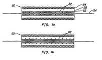
- FIGS. 3A and 3Bthe structures of two different membrane and electrode (M&E) assemblies specifically intended for use in a stack of electro-chemical cells in the form of monopolar fuel cells will be described wherein the internal electrically conductive element 82 of the anode in one cell extends and forms the conducting element in the cathode of an adjacent cell.
- M&Emembrane and electrode
- a metal grid 82is embedded in the front surface of the electrode 80 and is in direct contact with both the electrocatalytically active portion 56 of the electrode and the membrane 54.
- the electrode 80incorporates an uncatalysed gas diffusion layer 58.
- the electrocatalytically active portion 56is preferably a layer of a mixture of platinum black and perfluorosulphoric acid, or may comprise a mixture of platinum black and polytetrafluorothylene. The advantage of this arrangement is good electrical contact with the electrocatalyst for efficient current collection and the least interference with gas diffusion within the electrode.
- Figure 3Bshows an M&E configuration 85 with the metal grid 82 in the centre of the electrode, between the uncatalysed carbon gas diffusion layer 58 and the active electrocatalyst layer 56.
- the advantages of this configurationare good contact between the grid 82 and the electrocatalyst 56 for efficient current collection and no blockage of the interface between the membrane 54 and the active electrocatalyst 56.
- the disadvantages of this configurationare a more difficult fabrication procedure and possible interference with gas diffusion inside the electrode.
- the metal grids of Figures 3A and 3Bprovide the support normally provided by the carbon cloth or carbon paper in conventional gas diffusion electrodes while adding in-plane conductivity to the electrode. Since the metal grid is quite close to the membrane in this design, it is imperative that the metal not corrode. Corrosion will not only increase the contact resistance between the active portion of the electrode and the current collecting frame, but mobile metal ions coming in contact with the membrane may replace protons in the membrane. Replacing even a small fraction of the protons in the membrane with far less mobile metal ions will lead to a significant drop in membrane conductivity. This factor imposes a requirement that the grids have low contact resistance and be corrosion resistant. The best way to impart these properties to a piece of lightweight material is to plate the metal with a layer of a more precious metal, such as gold, platinum, palladium or ruthenium, or combinations thereof to protect it from corrosion and to improve electrical contacts.
- a more precious metalsuch as gold, platinum, palladium or ruthenium, or combinations thereof to protect it from corrosion
- FIG 4is an exploded view of a subassembly 120 including a pair of gas diffusion electrodes 122 fabricated with internal bipolar conductive metal grids, made in accordance with Figure 3b.
- the electrodes 122each comprise an active cathodic catalyst region 126, an active anodic catalyst region 128 and a gas barrier 130 disposed therebetween.
- a proton exchange membrane 132preferably having a PTFE frame 134 is disposed between the cathodic region of one electrode and the anodic region of another electrode. While each active catalytic region is shown as having the catalyst deposited on one surface of the gas diffusion matrix, it is also possible to deposit a thin layer electrode on the surface of the membrane.
- one surface of the gas diffusion electrodeis catalysed on one side of the gas barrier and the opposite surface is catalysed on the other side.
- the diffusion backingis bonded to the back of the electrode, and the gas diffusion matrix can be fabricated as a symmetrical unit, i.e. it is not necessary to deposit catalyst on either side thereof.
- the electrodesare assembled with a PEM membrane between them and a PTFE "window frame" gasket included to eliminate the possibility of electrodes shorting at the edge due to physical contact of the anode 128 and cathode 126.
- each gridhas both an anode and a cathode bonded to it and serves as the bipolar link between them. This eliminates the need for bipolar cell frames.
- the conductive elements within the electrodesserve as the bipolar elements connecting each pair of adjacent cells.
- PTFE framesare included to prevent shorting from electrode at the edge.
- the gas barrier strip 130 disposed down the centre of the conductive metal gridcan be fabricated in a variety of ways.
- a polymer stripcan be deposited using a self-curing polymer, such as silicones, epoxies and urethanes; a thermoplastic or easily melted metals, such as solder.
- the barriercan also be produced as part of the grid fabrication process with the gas barrier strip 130 comprising a region of un-expanded metal. It can be readily appreciated by those skilled in the art that other methods may be used in producing light weight fuel cells, such methods are considered to be within the scope of the present invention.
- the conductive metal elementwithin the gas diffusion electrode.
- Those described hereare only examples, the use of materials not described here is within the scope of the present invention.
- the preferred material for the conductive elementis expanded metal, a product fabricated by piercing and stretching a sheet of metal or metallic foil. For optimal performance, the metal should be flattened after expansion to restore it to its original thickness.
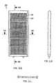
- Figure 5shows the basic form of the expanded metal sheet used in conjunction with this invention.
- Expanded metal foils with the pattern shown as well as othersare available from a wide variety of manufacturers, in a wide range of thickness, from 0.003" (0.076 mm) to 0.1" (2.5 mm) or more and manufactured from a variety of metals, including, but not limited to, titanium, nickel, copper, stainless steel, aluminum, and niobium. They are available with open areas (the percentage of the sheet area comprised of the holes) ranging from 10% to 70%.
- a typical expanded metal sheethas two primary directions.
- the expanded metal sheetshould be oriented such that the current flows in the direction parallel to the "long way" of the diamond, since the electrical resistance is lowest in this direction, as shown in Table I, which contains some properties of typical expanded metals and other materials useful for forming the conductive portion of the electrode structures, as taught here. Some of the materials in this table were gold plated prior electrical measurements so that contact resistance is reduced.
- Perforated metal sheetsare also suitable as the conductive component within the electrode. Compared to expanded metal, perforated metal sheets are generally stronger and more conductive, but generally display a smaller open fraction ( ⁇ 40%) and are thus less conducive to gas exchange.
- Woven metal wire productsare suitable as well. Compared to expanded metal, woven products have more open area (up to 80%) for superior gas exchange. However, the weaving process makes woven metal wire products more expensive to manufacture than expanded metal, and, because electrical conductivity requires that the current flow through a large number of wire-to-wire contacts, resistivity is high Furthermore, because of the woven nature of the material, any individual sheet can only be as thin as twice the wire diameter.
- Conventional carbon cloth supported gas diffusion electrodeshave a gas diffusion matrix consisting of conductive carbon powder bound together, and to the carbon cloth, by polytetrafluorethylene (PTFE). Since the expanded metal has substantially more open area than the carbon cloth, a modification of the gas diffusion matrix formulation would be advantageous. It has been found that replacing a portion of the carbon powder with finely cut and divided conductive carbon fibres produces a superior gas diffusion matrix. The inclusion of conductive carbon fibres in the gas diffusion matrix improves the matrix's ability to span the large gaps in the expanded metal, or other open metal, used as the conducive support.
- PTFEpolytetrafluorethylene
- Figures 6 (a-c)are three views of a fin depicting a compact fuel cell arrangement.
- two sets of cellsfabricated using a common conductive element in the electrodes as the polar element, are attached to opposing faces of a single polymeric frame configured for liquid fuel use.
- Figure 6 (a)is a top view of a hydrogen/air fuel cell system 310 showing the top view of a fin 311 defining a cathodic surface 313.
- Figure 6 (b)is a cross-sectional view of the fin 311 cut vertically near the centre of the arrangement shown in Figure 6 (a).
- Figure 6 (c)is a cross-sectional view cut horizontally near the centre of Figure 31 (a).
- a large fraction of the external surface of the fuel cell assemblyserves as active cathode area.
- the fins of Figure 6can be used as the basic structural element in larger arrangements. These fins can also be operated individually in small power supplies. While the fin of Figure 6 comprises two sets of 5 cells each for a total number of 10 cells connected in series, there are no limitations on the number of 10 cells that can be connected in the manner described here. Arrangements with a larger or a smaller number of cells are considered within the scope of the present invention. Also, it is not a necessary element of this invention to make symmetrical fins with the same number of cells on two sides, non-symmetrical arrangements are variations within the scope of the present invention. The arrangement described in this invention presents high flexibility. Adjustments in the number of cells and their arrangement are provided for by the present invention so that optimum use is obtained in any particular application.
Landscapes
- Chemical & Material Sciences (AREA)
- Chemical Kinetics & Catalysis (AREA)
- Electrochemistry (AREA)
- Engineering & Computer Science (AREA)
- General Chemical & Material Sciences (AREA)
- Manufacturing & Machinery (AREA)
- Materials Engineering (AREA)
- Life Sciences & Earth Sciences (AREA)
- Sustainable Development (AREA)
- Sustainable Energy (AREA)
- Metallurgy (AREA)
- Organic Chemistry (AREA)
- Fuel Cell (AREA)
- Inert Electrodes (AREA)
Abstract
Description
| Properties of Metal Conductive Components | |||||||
| Label | Thickness (cm) | LWD (cm) | SWD (cm) | Areal density (g/cm2) | Resistivity (LWD) (mΩ cm/cm) | Resistivity (SWD) (mΩ cm/cm) | Open Fraction (%) |
| Ni #1 | 0.028 | 0.167 | 0.125 | 0.01994 | 6.08 | 9.62 | 51 |
| Ni #2 | 0.028 | 0.172 | 0.125 | 0.01977 | 5.72 | 10.34 | 56.5 |
| Ni #3 | 0.0285 | 0.325 | 0.112 | 0.03046 | 2.79 | 10.0 | 43 |
| Ni #4 | 0.016 | 0.186 | 0.110 | 0.0493 | 1.78 | 4.68 | 35 |
| Ni D | 0.041 | 0.185 | 0.113 | 0.0383 | 2.62 | 9.25 | 41 |
| Ti 77 | 0.009 | 0.138 | 0.075 | 0.0093 | 35 | 119 | 52 |
| SS 080 | 0.014 | 0.123 | 0.071 | 0.0288 | 33 | 82 | 314 |
| SS 4/0 | 0.009 | 0.1 | 0.079 | 0.0185 | 50 | 133 | 34 |
| 0.011 | 0.134 | 0.1 | 0.0219 | 42 | 123 | 40 | |
| Cu 4/3 | 0.0172 | 0.14 | 0.0074 | 0.0545 | 0.38 | 1.17 | 31 |
| Cu 3/0 | 0.017 | 0.2 | 0.09 | 0.06958 | 0.26 | 0.93 | 37.8 |
| Ni Foam | 0.05 | n.a. | n.a. | 0.0853 | 3.2 | n.a | 68 |
| Perf. SS | 0.0135 | n.a. | n.a. | 0.06 | 6.7 | n.a | 38 |
Claims (12)
- An apparatus comprising an array of electrochemical cells; eachelectrochemical cell having a proton exchange membrane, an anode comprisinga conductive element and in contact with a first side of the proton exchangemembrane, and a cathode comprising a conductive element and in contact witha second side of the proton exchange membranecharacterised in that a commonintegral electrically conducting grid is used which comprises an anodic regionused to form the anode of a first cell and a cathodic region used to form thecathode of a second cell, said regions being separated by a gas barrier region,the grid constituting a conductive element shared by the anode of one cell andthe cathode of an adjacent cell to establish electrical connection between thecells of the array.
- The apparatus of Claim 1 wherein the electrically conducting grid isdisposed within the anode of said first cell and within the cathode of saidsecond cell.
- The apparatus of any one of Claims 1 or 2 wherein the anode has anelectrocatalyst layer and a gas diffusion layer, and wherein the electricallyconducting grid is disposed in contact between the active electrocatalyst layerand the gas diffusion layer.
- The apparatus of any one of Claims 1 or 2 wherein the cathode has anelectrocatalyst layer and a gas diffusion layer, and wherein the electricallyconducting grid is disposed in contact between the active electrocatalyst layerand gas diffusion layer.
- The apparatus of any one of Claims 3 or 4 wherein the electrocatalystlayer comprises a mixture of platinum black and perfluorosulfonic acid.
- The apparatus of any one of Claims 3 or 4 wherein the electrocatalystlayer comprises a mixture of platinum black and polytetrafluoroethylene.
- The apparatus of any one of the preceding Claims wherein theelectrically conducting grid is selected from metal mesh, woven metal wire,expanded metal, perforated metal sheet, metal foam, intrinsically conductingpolymers, graphite cloth, or intrinsically non-conducting polymers mixed withconductive particles, fibres or flakes.
- The apparatus of any one of the preceding Claims wherein theelectrically conducting grid is a metal grid.
- The apparatus of Claim 8 wherein the electrically conducting grid ismade from a metal selected from titanium, nickel, copper, stainless steel,aluminium, niobium or combinations thereof.
- The apparatus of Claim 8 or 9 wherein the metal grid is plated with alayer of a more precious metal selected from gold, platinum, palladium,ruthenium or combinations thereof.
- The apparatus of any one of the preceding Claims wherein the array ofelectrochemical cells are selected from electrolytic cells and fuel cells.
- The apparatus of any one of the preceding Claims wherein the protonexchange membrane comprises a perfluorinated sulfonic acid polymer.
Priority Applications (1)
| Application Number | Priority Date | Filing Date | Title |
|---|---|---|---|
| EP03011855AEP1339120A3 (en) | 1997-09-10 | 1998-09-10 | Fuel cell electrode for low pressure operation |
Applications Claiming Priority (3)
| Application Number | Priority Date | Filing Date | Title |
|---|---|---|---|
| US08/926,547US6054228A (en) | 1996-06-06 | 1997-09-10 | Fuel cell system for low pressure operation |
| US926547 | 1997-09-10 | ||
| PCT/US1998/019221WO1999034467A2 (en) | 1997-09-10 | 1998-09-10 | Fuel cell system for low pressure operation |
Related Child Applications (1)
| Application Number | Title | Priority Date | Filing Date |
|---|---|---|---|
| EP03011855ADivisionEP1339120A3 (en) | 1997-09-10 | 1998-09-10 | Fuel cell electrode for low pressure operation |
Publications (2)
| Publication Number | Publication Date |
|---|---|
| EP1025605A2 EP1025605A2 (en) | 2000-08-09 |
| EP1025605B1true EP1025605B1 (en) | 2003-07-16 |
Family
ID=25453360
Family Applications (2)
| Application Number | Title | Priority Date | Filing Date |
|---|---|---|---|
| EP03011855AWithdrawnEP1339120A3 (en) | 1997-09-10 | 1998-09-10 | Fuel cell electrode for low pressure operation |
| EP98948243AExpired - LifetimeEP1025605B1 (en) | 1997-09-10 | 1998-09-10 | Fuel cell system for low pressure operation |
Family Applications Before (1)
| Application Number | Title | Priority Date | Filing Date |
|---|---|---|---|
| EP03011855AWithdrawnEP1339120A3 (en) | 1997-09-10 | 1998-09-10 | Fuel cell electrode for low pressure operation |
Country Status (7)
| Country | Link |
|---|---|
| US (5) | US6054228A (en) |
| EP (2) | EP1339120A3 (en) |
| AT (1) | ATE245311T1 (en) |
| AU (1) | AU9485898A (en) |
| DE (1) | DE69816468T2 (en) |
| ES (1) | ES2198754T3 (en) |
| WO (1) | WO1999034467A2 (en) |
Families Citing this family (193)
| Publication number | Priority date | Publication date | Assignee | Title |
|---|---|---|---|---|
| US6054228A (en)* | 1996-06-06 | 2000-04-25 | Lynntech, Inc. | Fuel cell system for low pressure operation |
| US6221523B1 (en)* | 1998-02-10 | 2001-04-24 | California Institute Of Technology | Direct deposit of catalyst on the membrane of direct feed fuel cells |
| US6232010B1 (en)* | 1999-05-08 | 2001-05-15 | Lynn Tech Power Systems, Ltd. | Unitized barrier and flow control device for electrochemical reactors |
| DE19819291A1 (en)* | 1998-04-30 | 1999-11-11 | Emitec Emissionstechnologie | Fuel cell module |
| DE19829142A1 (en)* | 1998-06-30 | 2000-01-05 | Manhattan Scientifics Inc | Gas-tight combination of bipolar plate and membrane-electrode assembly of polymer electrolyte membrane fuel cells |
| JP2000182625A (en)* | 1998-12-11 | 2000-06-30 | Toyota Motor Corp | Fuel cell electrode and method of manufacturing the same |
| US6602631B1 (en)* | 1999-01-26 | 2003-08-05 | Lynntech Power Systems, Ltd. | Bonding electrochemical cell components |
| US6638659B1 (en)* | 1999-04-30 | 2003-10-28 | University Of Connecticut | Membrane electrode assemblies using ionic composite membranes |
| US6503654B2 (en)* | 1999-05-19 | 2003-01-07 | George A. Marchetti | Thin graphite bipolar plate with associated gaskets and carbon cloth flow-field for use in an ionomer membrane fuel cell |
| JP4423699B2 (en)* | 1999-05-27 | 2010-03-03 | ソニー株式会社 | Semiconductor laser device and manufacturing method thereof |
| DE19926026A1 (en)* | 1999-05-28 | 2000-11-30 | Heliocentris Energiesysteme | Membrane electrode unit for fuel cells and. the like |
| EP1077499A3 (en)* | 1999-08-17 | 2005-10-05 | Schmidlin Labor + Service AG | Electrolysis or fuel cell, electrode for electrolysis or for fuel cell and process for electrolysis or fuel cell |
| DE19939727A1 (en)* | 1999-08-21 | 2001-02-22 | Forschungszentrum Juelich Gmbh | Current collector for fuel cell has honeycomb, mesh or fibrous structure conductor grid embedded in porous diffusion layer and electronically coupled to collector-distributor plate |
| US6517962B1 (en)* | 1999-08-23 | 2003-02-11 | Ballard Power Systems Inc. | Fuel cell anode structures for voltage reversal tolerance |
| US6383677B1 (en) | 1999-10-07 | 2002-05-07 | Allen Engineering Company, Inc. | Fuel cell current collector |
| US6777126B1 (en) | 1999-11-16 | 2004-08-17 | Gencell Corporation | Fuel cell bipolar separator plate and current collector assembly and method of manufacture |
| US6641948B1 (en) | 1999-11-17 | 2003-11-04 | Neah Power Systems Inc | Fuel cells having silicon substrates and/or sol-gel derived support structures |
| US6403247B1 (en)* | 1999-12-03 | 2002-06-11 | International Fuel Cells, Llc | Fuel cell power plant having an integrated manifold system |
| US7281681B2 (en) | 2000-04-03 | 2007-10-16 | Aerovironment Inc. | Hydrogen powered aircraft |
| US6550717B2 (en)* | 2000-04-03 | 2003-04-22 | Aerovironment, Inc. | Liquid hydrogen stratospheric aircraft |
| US7802756B2 (en) | 2000-02-14 | 2010-09-28 | Aerovironment Inc. | Aircraft control system |
| US6602626B1 (en) | 2000-02-16 | 2003-08-05 | Gencell Corporation | Fuel cell with internal thermally integrated autothermal reformer |
| DE10013351A1 (en)* | 2000-03-17 | 2001-09-27 | Forschungszentrum Juelich Gmbh | Fuel cell stack has space only for delivery or removal of working medium between adjacent identical electrodes of two individual cells |
| HK1054620A1 (en) | 2000-03-17 | 2003-12-05 | Gencell Corporation | Fuel cell stack assembly |
| AU2001250054A1 (en) | 2000-03-30 | 2001-10-15 | Manhattan Scientifics, Inc. | Diffusion fuel ampoules for fuel cells |
| US6680139B2 (en) | 2000-06-13 | 2004-01-20 | California Institute Of Technology | Reduced size fuel cell for portable applications |
| WO2001097314A1 (en) | 2000-06-13 | 2001-12-20 | California Institute Of Technology | Reduced size fuel cell for portable applications |
| US6663994B1 (en)* | 2000-10-23 | 2003-12-16 | General Motors Corporation | Fuel cell with convoluted MEA |
| US7592089B2 (en)* | 2000-08-31 | 2009-09-22 | Gm Global Technology Operations, Inc. | Fuel cell with variable porosity gas distribution layers |
| EP1489675A3 (en)* | 2000-09-15 | 2006-04-19 | Lynntech, Inc. | Bonding electrochemical cell components |
| US6531238B1 (en) | 2000-09-26 | 2003-03-11 | Reliant Energy Power Systems, Inc. | Mass transport for ternary reaction optimization in a proton exchange membrane fuel cell assembly and stack assembly |
| US6824899B2 (en)* | 2000-11-22 | 2004-11-30 | Mti Microfuel Cells, Inc. | Apparatus and methods for sensor-less optimization of methanol concentration in a direct methanol fuel cell system |
| US6589679B1 (en) | 2000-11-22 | 2003-07-08 | Mti Microfuel Cells Inc. | Apparatus and methods for sensor-less optimization of methanol concentration in a direct methanol fuel cell system |
| US6797422B2 (en)* | 2001-01-25 | 2004-09-28 | Gas Technology Institute | Air-breathing direct methanol fuel cell with metal foam current collectors |
| US6503653B2 (en) | 2001-02-23 | 2003-01-07 | General Motors Corporation | Stamped bipolar plate for PEM fuel cell stack |
| ITMI20010459A1 (en)* | 2001-03-06 | 2002-09-06 | Nuvera Fuel Cells Europ Srl | METHODS FOR THE OPERATION OF FUEL CELLS SUPPLIED WITH GAS CONTAINING HYDROGEN CARBON MONOXIDE AND DEVICES |
| US6632553B2 (en)* | 2001-03-27 | 2003-10-14 | Mti Microfuel Cells, Inc. | Methods and apparatuses for managing effluent products in a fuel cell system |
| EP1383184B1 (en)* | 2001-04-27 | 2017-03-08 | Panasonic Intellectual Property Management Co., Ltd. | Electrode for fuel cell and method of manufacturing the electrode |
| US20020192537A1 (en)* | 2001-06-15 | 2002-12-19 | Xiaoming Ren | Metallic layer component for use in a direct oxidation fuel cell |
| US20030008193A1 (en)* | 2001-06-28 | 2003-01-09 | Foamex L.P. | Liquid fuel delivery system for fuel cells |
| US6994932B2 (en)* | 2001-06-28 | 2006-02-07 | Foamex L.P. | Liquid fuel reservoir for fuel cells |
| GB0117939D0 (en)* | 2001-07-24 | 2001-09-19 | Rolls Royce Plc | A solid oxide fuel cell stack |
| DE10136755A1 (en)* | 2001-07-27 | 2003-02-20 | Siemens Ag | Portable direct-methanol fuel cell for laptops and mobile telephones has a fuel cell unit made from a polymer membrane with an anode and cathode forming a membrane electrode unit, anode/cathode areas and a reservoir for methanol |
| JP4094265B2 (en)* | 2001-09-25 | 2008-06-04 | 株式会社日立製作所 | Fuel cell power generator and device using the same |
| US6838205B2 (en) | 2001-10-10 | 2005-01-04 | Lynntech, Inc. | Bifunctional catalytic electrode |
| US6828049B2 (en)* | 2001-10-29 | 2004-12-07 | Hewlett-Packard Development Company, L.P. | Replaceable fuel cell apparatus having information storage device |
| US6713201B2 (en) | 2001-10-29 | 2004-03-30 | Hewlett-Packard Development Company, L.P. | Systems including replaceable fuel cell apparatus and methods of using replaceable fuel cell apparatus |
| US20030091888A1 (en)* | 2001-11-15 | 2003-05-15 | Goggin Christopher M. | High-density, wireless fuel cell power unit |
| US6716549B2 (en)* | 2001-12-27 | 2004-04-06 | Avista Laboratories, Inc. | Fuel cell having metalized gas diffusion layer |
| DE10164480A1 (en)* | 2001-12-29 | 2003-07-17 | Schumacher Umwelt Trenntech | filter element |
| US6670071B2 (en)* | 2002-01-15 | 2003-12-30 | Quallion Llc | Electric storage battery construction and method of manufacture |
| US6677076B2 (en)* | 2002-01-15 | 2004-01-13 | Quallion Llc | Electric storage battery construction and method of manufacture |
| US20030138679A1 (en)* | 2002-01-22 | 2003-07-24 | Ravi Prased | Fuel cartridge and reaction chamber |
| US6887596B2 (en) | 2002-01-22 | 2005-05-03 | Hewlett-Packard Development Company, L.P. | Portable disposable fuel-battery unit for a fuel cell system |
| US6981877B2 (en)* | 2002-02-19 | 2006-01-03 | Mti Microfuel Cells Inc. | Simplified direct oxidation fuel cell system |
| KR100450820B1 (en)* | 2002-04-23 | 2004-10-01 | 삼성에스디아이 주식회사 | Air breathing direct methanol fuel cell pack |
| US6811905B1 (en) | 2002-05-21 | 2004-11-02 | Giner Electro Chemical Systems, Llc | Direct organic fuel cell having a vapor transport member |
| AU2003238801A1 (en)* | 2002-05-31 | 2003-12-19 | Lynntech, Inc. | Electrochemical cell and bipolar assembly for an electrochemical cell |
| US7045244B2 (en)* | 2002-06-10 | 2006-05-16 | Hewlett-Packard Development Company, L.P. | Fuel cells utilizing non-porous nanofilm microchannel architecture |
| US20040001991A1 (en)* | 2002-07-01 | 2004-01-01 | Kinkelaar Mark R. | Capillarity structures for water and/or fuel management in fuel cells |
| JP2005531901A (en)* | 2002-06-28 | 2005-10-20 | フォーメックス エル ピー | Fuel storage tank for liquid fuel cell |
| US7198866B2 (en)* | 2002-07-09 | 2007-04-03 | Nissan Motor Co., Ltd. | Cell assembly |
| US20040033397A1 (en)* | 2002-08-14 | 2004-02-19 | Ballard Power Systems Inc. | Direct dimethoxymethane and methanol fuel cells |
| CA2436313A1 (en)* | 2002-08-14 | 2004-02-14 | Hewlett-Packard Development Company, L.P. | Fuel-cell element stack with stress relief and methods |
| JP4249960B2 (en)* | 2002-08-28 | 2009-04-08 | 新光電気工業株式会社 | Fuel cell |
| US20040053100A1 (en)* | 2002-09-12 | 2004-03-18 | Stanley Kevin G. | Method of fabricating fuel cells and membrane electrode assemblies |
| US7291410B2 (en)* | 2002-09-18 | 2007-11-06 | Kinkelaar Mark R | Orientation independent liquid fuel reservoir |
| US20040058220A1 (en)* | 2002-09-20 | 2004-03-25 | Qin Liu | Fuel cell reactant and byproduct systems |
| US20040062980A1 (en)* | 2002-09-30 | 2004-04-01 | Xiaoming Ren | Fluid management component for use in a fuel cell |
| US7297430B2 (en) | 2002-10-01 | 2007-11-20 | Mti Microfuel Cells, Inc. | Anode diffusion layer for a direct oxidation fuel cell |
| US20040067406A1 (en)* | 2002-10-03 | 2004-04-08 | David Champion | Fuel cell manifold |
| US7001687B1 (en) | 2002-10-04 | 2006-02-21 | The Texas A&M University System | Unitized MEA assemblies and methods for making same |
| US7005209B1 (en) | 2002-10-04 | 2006-02-28 | The Texas A&M University System | Fuel cell stack assembly |
| US7731491B2 (en)* | 2002-10-16 | 2010-06-08 | Hewlett-Packard Development Company, L.P. | Fuel storage devices and apparatus including the same |
| US20040166397A1 (en)* | 2002-11-08 | 2004-08-26 | Valdez Thomas I. | Cathode structure for direct methanol fuel cell |
| US7282291B2 (en)* | 2002-11-25 | 2007-10-16 | California Institute Of Technology | Water free proton conducting membranes based on poly-4-vinylpyridinebisulfate for fuel cells |
| US7736783B2 (en)* | 2002-12-04 | 2010-06-15 | Lynntech, Inc. | Very thin, light bipolar plates |
| EP1568095A2 (en)* | 2002-12-04 | 2005-08-31 | Lynntech Power Systems Limited | Adhesively bonded electrochemical cell stacks |
| JP4292368B2 (en)* | 2002-12-12 | 2009-07-08 | ソニー株式会社 | Fuel cell and electronic device equipped with the same |
| WO2005091403A1 (en)* | 2003-01-15 | 2005-09-29 | Quallion Llc | Battery |
| US6772617B1 (en) | 2003-01-24 | 2004-08-10 | Gencell Corporation | Method and apparatus for in-situ leveling of progressively formed sheet metal |
| US7147955B2 (en)* | 2003-01-31 | 2006-12-12 | Societe Bic | Fuel cartridge for fuel cells |
| US7056608B2 (en) | 2003-02-14 | 2006-06-06 | Relion, Inc. | Current collector for use in a fuel cell |
| US7404878B2 (en)* | 2003-03-31 | 2008-07-29 | Chlorine Engineers Corp., Ltd. | Gas diffusion electrode assembly, bonding method for gas diffusion electrodes, and electrolyzer comprising gas diffusion electrodes |
| US7407721B2 (en)* | 2003-04-15 | 2008-08-05 | Mti Microfuel Cells, Inc. | Direct oxidation fuel cell operating with direct feed of concentrated fuel under passive water management |
| US20050170224A1 (en)* | 2003-04-15 | 2005-08-04 | Xiaoming Ren | Controlled direct liquid injection vapor feed for a DMFC |
| US7282293B2 (en)* | 2003-04-15 | 2007-10-16 | Mti Microfuel Cells Inc. | Passive water management techniques in direct methanol fuel cells |
| US7459227B2 (en)* | 2003-04-18 | 2008-12-02 | General Motors Corporation | Stamped fuel cell bipolar plate |
| US6939636B2 (en)* | 2003-04-28 | 2005-09-06 | Relion, Inc. | Air cooled fuel cell module |
| US7308510B2 (en)* | 2003-05-07 | 2007-12-11 | Intel Corporation | Method and apparatus for avoiding live-lock in a multinode system |
| US7093623B2 (en)* | 2003-06-27 | 2006-08-22 | The Gillette Company | Methods of providing refueling for fuel cell-powered devices |
| US7052587B2 (en)* | 2003-06-27 | 2006-05-30 | General Motors Corporation | Photoelectrochemical device and electrode |
| TWI251954B (en)* | 2003-07-29 | 2006-03-21 | Ind Tech Res Inst | Flat fuel cell assembly and fabrication thereof |
| US20050048346A1 (en)* | 2003-08-28 | 2005-03-03 | Fannon Megan A. | Modular connections in a DMFC array |
| US6974648B2 (en)* | 2003-09-12 | 2005-12-13 | General Motors Corporation | Nested bipolar plate for fuel cell and method |
| US7489859B2 (en)* | 2003-10-09 | 2009-02-10 | Hewlett-Packard Development Company, L.P. | Fuel storage devices and apparatus including the same |
| US20050112436A1 (en)* | 2003-11-25 | 2005-05-26 | Carol Jeffcoate | Methods and devices for heating or cooling fuel cell systems |
| US7595126B2 (en)* | 2003-11-26 | 2009-09-29 | Delphi Technologies, Inc. | PEM fuel cell assembly formed of modular sub-assemblies |
| DE10356012A1 (en)* | 2003-11-27 | 2005-06-30 | Airbus Deutschland Gmbh | Arrangement and method for producing water on board an aircraft |
| US20050136317A1 (en)* | 2003-12-19 | 2005-06-23 | 3M Innovative Properties Company | Molded multi-part flow field structure |
| WO2005064731A2 (en)* | 2003-12-23 | 2005-07-14 | Universität Stuttgart | Electrochemical cell arrangement having a pocket-shaped structure |
| US8486575B2 (en)* | 2004-02-05 | 2013-07-16 | GM Global Technology Operations LLC | Passive hydrogen vent for a fuel cell |
| US7510640B2 (en)* | 2004-02-18 | 2009-03-31 | General Motors Corporation | Method and apparatus for hydrogen generation |
| US7459065B2 (en)* | 2004-02-18 | 2008-12-02 | General Motors Corporation | Hydrogen generator photovoltaic electrolysis reactor system |
| US7662498B2 (en)* | 2004-04-23 | 2010-02-16 | Asahi Kasei Chemicals Corporation | Polymer electrolyte composition containing aromatic hydrocarbon-based resin |
| US8084150B2 (en)* | 2004-04-28 | 2011-12-27 | Eveready Battery Company, Inc. | Fuel cartridges and apparatus including the same |
| US7378176B2 (en)* | 2004-05-04 | 2008-05-27 | Angstrom Power Inc. | Membranes and electrochemical cells incorporating such membranes |
| US7632587B2 (en) | 2004-05-04 | 2009-12-15 | Angstrom Power Incorporated | Electrochemical cells having current-carrying structures underlying electrochemical reaction layers |
| US20080271377A1 (en)* | 2004-06-18 | 2008-11-06 | H2Volt, Inc. | Combination Metal-Based and Hydride-Based Hydrogen Sources and Processes for Producing Hydrogen |
| DE112005001405T5 (en)* | 2004-06-18 | 2007-08-09 | General Motors Corp. (N.D.Ges.D. Staates Delaware), Detroit | System and systems for the production and use of hydrogen |
| US7410714B1 (en) | 2004-07-15 | 2008-08-12 | The United States Of America As Represented By The Administration Of Nasa | Unitized regenerative fuel cell system |
| TWI241735B (en)* | 2004-07-22 | 2005-10-11 | Delta Electronics Inc | Panel-form fuel cell assembly |
| US7604888B2 (en)* | 2004-07-30 | 2009-10-20 | Gm Global Technologies Operations, Inc. | Stamped PEM fuel cell plate manufacturing |
| CN100334761C (en)* | 2004-08-03 | 2007-08-29 | 财团法人工业技术研究院 | Planar fuel cell stack, fuel cell unit and manufacturing method thereof |
| DE102004048526A1 (en)* | 2004-08-12 | 2006-02-23 | Bayerische Motoren Werke Ag | Fuel Cell System |
| TWM262846U (en)* | 2004-08-31 | 2005-04-21 | Antig Tech Co Ltd | Semi-active fuel cell device |
| JP4887639B2 (en)* | 2005-03-11 | 2012-02-29 | 株式会社エクォス・リサーチ | Separator unit and fuel cell stack |
| CA2601445C (en)* | 2005-03-16 | 2012-10-02 | Fuelcor Llc | Systems, methods, and compositions for production of synthetic hydrocarbon compounds |
| TW200640072A (en)* | 2005-04-14 | 2006-11-16 | H2 Volt Inc | Integrated fuel and fuel cell device |
| EP1715538A1 (en)* | 2005-04-19 | 2006-10-25 | Nicholas M. Abson | Novel materials for alkaline fuel cells |
| EP1724861A1 (en)* | 2005-05-17 | 2006-11-22 | Nicholas M. Abson | Novel materials for alkaline electrolysers and alkaline fuel cells |
| US8003275B2 (en)* | 2005-05-24 | 2011-08-23 | Samsung Sdi Co., Ltd. | Monopolar membrane-electrode assembly |
| DE102005038195A1 (en)* | 2005-08-12 | 2007-02-15 | Pemeas Gmbh | Improved membrane electrode assemblies and fuel cells with long life |
| CN100449833C (en)* | 2005-08-26 | 2009-01-07 | 比亚迪股份有限公司 | A flow field plate for a fuel cell |
| ATE469874T1 (en)* | 2005-09-20 | 2010-06-15 | Arkema France | METHOD FOR PRODUCING PARTIALLY OXIDIZED LOWER ALCOHOL PRODUCTS BY DIRECT OXIDATION OF A LOWER ALCOHOL, AND CATALYSTS FOR USE IN THIS METHOD |
| EP1780822B1 (en)* | 2005-11-01 | 2012-01-18 | Tomoegawa Co., Ltd. | Gas diffusion electrode, membrane-electrode assembly, polymer electrolyte fuel cell, and methods for producing |
| CA2629087A1 (en)* | 2005-11-18 | 2007-05-24 | Ballard Power Systems Inc. | Method of operating a fuel cell stack at low pressure and low power conditions |
| US20090130500A1 (en)* | 2005-11-18 | 2009-05-21 | Wozniczka Boguslaw M | Method of operating a fuel cell stack at low pressure and low power conditions |
| US7833645B2 (en) | 2005-11-21 | 2010-11-16 | Relion, Inc. | Proton exchange membrane fuel cell and method of forming a fuel cell |
| EP2469636A1 (en)* | 2005-11-23 | 2012-06-27 | The Regents of The University of California | Electrochemical cell holder and stack |
| CN101336493B (en)* | 2006-02-09 | 2010-12-08 | 卡尔弗罗伊登柏格两合公司 | Gas diffusion unit |
| US8007952B2 (en)* | 2006-03-27 | 2011-08-30 | Sanyo Electric Co., Ltd. | Fuel cell |
| KR100738061B1 (en)* | 2006-05-16 | 2007-07-10 | 삼성에스디아이 주식회사 | Monopolar Membrane Electrode Assembly |
| US20100012499A1 (en)* | 2006-06-01 | 2010-01-21 | Yu Zhou | Fuel cell charger |
| JP5184795B2 (en)* | 2006-06-06 | 2013-04-17 | シャープ株式会社 | FUEL CELL, FUEL CELL SYSTEM, AND ELECTRONIC DEVICE |
| US7838168B2 (en)* | 2006-08-24 | 2010-11-23 | Salter L Carlton | Functionally integrated hydrogen fuel cell |
| DE102006041503B4 (en)* | 2006-08-31 | 2009-08-20 | Fraunhofer-Gesellschaft zur Förderung der angewandten Forschung e.V. | Fuel cell assembly and method of manufacturing the fuel cell assembly |
| GB0617806D0 (en)* | 2006-09-11 | 2006-10-18 | Johnson Matthey Plc | Fuel cell assembly |
| DE102006049031B4 (en) | 2006-10-13 | 2009-10-22 | Futuree Fuel Cell Solutions Gmbh | Carrying container of a power supply unit with fuel cells, its use and method for risk reduction |
| KR101357146B1 (en) | 2006-11-15 | 2014-02-05 | 주식회사 동진쎄미켐 | Electrode for fuel cell, membrane electrode assembly with the electrode, fuel cell with the electrode and method for manufacturing the same |
| KR100786480B1 (en)* | 2006-11-30 | 2007-12-17 | 삼성에스디아이 주식회사 | Module type fuel cell system |
| US20080145736A1 (en)* | 2006-12-15 | 2008-06-19 | Pratt Steven D | Fluid Distribution Device for Fuel Cell Power Systems |
| KR100811982B1 (en)* | 2007-01-17 | 2008-03-10 | 삼성에스디아이 주식회사 | Fuel cell system and control method thereof |
| KR100805527B1 (en)* | 2007-02-15 | 2008-02-20 | 삼성에스디아이 주식회사 | Fuel cell for small mobile power source and membrane-electrode assembly used in this fuel cell |
| US20080199740A1 (en)* | 2007-02-20 | 2008-08-21 | Commonwealth Scientific And Industrial Research Organisation | Interconnect of a planar fuel cell array |
| US20080199751A1 (en)* | 2007-02-20 | 2008-08-21 | Commonwealth Scientific And Industrial Research Organisation | Bipolar plate for an air breathing fuel cell stack |
| JP2008243788A (en)* | 2007-02-28 | 2008-10-09 | Toyota Motor Corp | Fuel cell |
| WO2008104860A1 (en)* | 2007-02-28 | 2008-09-04 | Toyota Jidosha Kabushiki Kaisha | Fuel cell |
| KR100844785B1 (en)* | 2007-03-29 | 2008-07-07 | 삼성에스디아이 주식회사 | Pump drive module and fuel cell system having same |
| US20080248366A1 (en)* | 2007-04-03 | 2008-10-09 | National Tsing Hua University | Fuel cell with a combined fuel supply unit and power generating unit structure |
| CN101281978B (en)* | 2007-04-04 | 2011-02-02 | 扬光绿能股份有限公司 | Fuel cell system |
| KR100863725B1 (en)* | 2007-04-25 | 2008-10-16 | 삼성전기주식회사 | Hydrogen Generator and Fuel Cell Power Generation System |
| US8026020B2 (en) | 2007-05-08 | 2011-09-27 | Relion, Inc. | Proton exchange membrane fuel cell stack and fuel cell stack module |
| US20100099005A1 (en)* | 2007-05-15 | 2010-04-22 | Xiaoming Ren | Vapor fed direct hydrocarbon alkaline fuel cells |
| US9293778B2 (en) | 2007-06-11 | 2016-03-22 | Emergent Power Inc. | Proton exchange membrane fuel cell |
| EP2182572A4 (en)* | 2007-08-02 | 2016-10-19 | Sharp Kk | FUEL CELL STACK AND FUEL CELL SYSTEM |
| US8790842B2 (en)* | 2007-09-25 | 2014-07-29 | Societe Bic | Fuel cell systems including space-saving fluid plenum and related methods |
| WO2009039654A1 (en)* | 2007-09-25 | 2009-04-02 | Angstrom Power Incorporated | Fuel cell cover |
| KR100911964B1 (en)* | 2007-10-17 | 2009-08-13 | 삼성에스디아이 주식회사 | Air-breathing polymer electrolyte membrane fuel cell and its operation control method |
| US8003274B2 (en) | 2007-10-25 | 2011-08-23 | Relion, Inc. | Direct liquid fuel cell |
| EP2245686B1 (en) | 2008-01-17 | 2013-04-10 | Société BIC | Covers for electrochemical cells and related methods |
| WO2009105896A1 (en)* | 2008-02-29 | 2009-09-03 | Angstrom Power Incorporated | Electrochemical cell and membranes related thereto |
| US20090263700A1 (en)* | 2008-04-17 | 2009-10-22 | Us Government As Represented By Secretary Of The Army | Fuel cell assembly |
| KR100999092B1 (en)* | 2008-06-24 | 2010-12-08 | 삼성전기주식회사 | Current collector, manufacturing method and stack and fuel cell system |
| DE102008032263A1 (en)* | 2008-07-09 | 2010-01-21 | Li-Tec Battery Gmbh | According to galvanic principles working electrical device |
| KR101000697B1 (en)* | 2008-07-17 | 2010-12-10 | 현대자동차주식회사 | Metal separator for fuel cell and method for forming surface layer thereof |
| US20100028736A1 (en)* | 2008-08-01 | 2010-02-04 | Georgia Tech Research Corporation | Hybrid Ionomer Electrochemical Devices |
| US20100276279A1 (en)* | 2008-11-17 | 2010-11-04 | Etorus, Inc. | Electrolytic hydrogen generating system |
| US20110061376A1 (en)* | 2009-02-17 | 2011-03-17 | Mcalister Technologies, Llc | Energy conversion assemblies and associated methods of use and manufacture |
| JP2010238458A (en)* | 2009-03-30 | 2010-10-21 | Nec Corp | Fuel battery cell stack, fuel battery, and manufacturing method of fuel battery cell stack |
| JP5290402B2 (en) | 2009-04-01 | 2013-09-18 | シャープ株式会社 | Fuel cell stack and electronic device including the same |
| DE102009022946A1 (en) | 2009-05-08 | 2010-11-11 | Fraunhofer-Gesellschaft zur Förderung der angewandten Forschung e.V. | A fuel cell assembly |
| EP2481114A1 (en)* | 2009-09-24 | 2012-08-01 | Georgia Tech Research Corporation | Electrochemical devices based on multiple junction ionic conductive membranes |
| US20110111309A1 (en)* | 2009-11-10 | 2011-05-12 | Point Source Power, Inc. | Fuel cell system |
| TWI375347B (en) | 2009-11-20 | 2012-10-21 | Ind Tech Res Inst | Manufacture method of bi-polar plates of fuel cell and bi-polar plates thereof |
| US9546826B1 (en) | 2010-01-21 | 2017-01-17 | Hrl Laboratories, Llc | Microtruss based thermal heat spreading structures |
| US8921702B1 (en)* | 2010-01-21 | 2014-12-30 | Hrl Laboratories, Llc | Microtruss based thermal plane structures and microelectronics and printed wiring board embodiments |
| FR2955975B1 (en)* | 2010-01-29 | 2012-04-13 | St Microelectronics Tours Sas | DEVICE COMPRISING A HYDROGEN-AIR OR METHANOL-AIR TYPE FUEL CELL |
| US20110195368A1 (en)* | 2010-02-08 | 2011-08-11 | Alfred Little | Compressed gaseous oxidizer energy storage system |
| JP5693215B2 (en)* | 2010-12-28 | 2015-04-01 | 東ソー株式会社 | Ion exchange membrane electrolytic cell |
| TW201304252A (en)* | 2011-07-13 | 2013-01-16 | Life Resources Inc | Battery module |
| GB2488385B (en)* | 2011-09-23 | 2014-04-23 | Intelligent Energy Ltd | Fuel cell system |
| US20130115483A1 (en)* | 2011-10-25 | 2013-05-09 | Point Source Power, Inc. | Shield for high-temperature electrochemical device |
| FR3002953A1 (en)* | 2013-03-08 | 2014-09-12 | Ceram Hyd | MODULAR COUPLING ASSEMBLY OF ELECTROCHEMICAL UNITS |
| US9405067B2 (en) | 2013-03-13 | 2016-08-02 | Hrl Laboratories, Llc | Micro-truss materials having in-plane material property variations |
| CN104049212A (en)* | 2013-03-15 | 2014-09-17 | 北京航天动力研究所 | Low-pressure work performance test system for hydrogen-air fuel cell |
| US10090552B2 (en)* | 2013-07-03 | 2018-10-02 | Ph Matter, Llc | Liquid fuel battery |
| TWI473336B (en)* | 2014-01-15 | 2015-02-11 | Nat Univ Tsing Hua | Fuel cell incorporating wind power generating device |
| WO2018044236A1 (en)* | 2016-08-31 | 2018-03-08 | Temasek Polytechnic | Flow frame for electrochemical cells |
| WO2019068488A1 (en)* | 2017-10-03 | 2019-04-11 | Vito Nv | Carbon based electrode with large geometric dimensions |
| DE102019220097A1 (en)* | 2019-12-19 | 2021-06-24 | Robert Bosch Gmbh | Housing for receiving at least one fuel cell stack |
| EP4312553A1 (en) | 2021-03-30 | 2024-02-07 | Stepan Company | Agricultural formulations |
| KR102764703B1 (en)* | 2021-08-13 | 2025-02-11 | 서울대학교산학협력단 | Tubular polymer electrolyte membrane fuel cell stack |
Family Cites Families (66)
| Publication number | Priority date | Publication date | Assignee | Title |
|---|---|---|---|---|
| BE596662A (en) | 1959-11-03 | 1900-01-01 | ||
| US3134697A (en)* | 1959-11-03 | 1964-05-26 | Gen Electric | Fuel cell |
| GB937149A (en) | 1961-04-17 | 1963-09-18 | Exxon Research Engineering Co | Fuel cell electrode structures and fuel cell assemblies comprising such electrode structures |
| BE617375A (en)* | 1961-05-08 | 1900-01-01 | ||
| NL299669A (en)* | 1962-10-24 | |||
| US3297490A (en) | 1963-03-01 | 1967-01-10 | American Cyanamid Co | Process for preparing catalyst support and product thereof |
| US3297485A (en)* | 1963-04-26 | 1967-01-10 | Du Pont | Cascade battery |
| DE2208632C3 (en)* | 1972-02-24 | 1981-07-30 | Battelle-Institut E.V., 6000 Frankfurt | Process for the production of carbon-containing gas electrodes with a hydrophobic backing layer |
| US4175165A (en) | 1977-07-20 | 1979-11-20 | Engelhard Minerals & Chemicals Corporation | Fuel cell system utilizing ion exchange membranes and bipolar plates |
| US4176165A (en)* | 1977-12-22 | 1979-11-27 | Ppg Industries, Inc. | Treatment of alkyl lead-containing gas stream |
| US4214969A (en) | 1979-01-02 | 1980-07-29 | General Electric Company | Low cost bipolar current collector-separator for electrochemical cells |
| US4235693A (en)* | 1979-11-09 | 1980-11-25 | The United States Of America As Represented By The Secretary Of The Navy | Submersible energy storage apparatus |
| US4364805A (en)* | 1981-05-08 | 1982-12-21 | Diamond Shamrock Corporation | Gas electrode operation |
| US4476196A (en) | 1983-10-12 | 1984-10-09 | The United States Of America As Represented By The United States Department Of Energy | Solid oxide fuel cell having monolithic cross flow core and manifolding |
| US4476197A (en) | 1983-10-12 | 1984-10-09 | The United States Of America As Represented By The United States Department Of Energy | Integral manifolding structure for fuel cell core having parallel gas flow |
| US4510212A (en) | 1983-10-12 | 1985-04-09 | The United States Of America As Represented By The United States Department Of Energy | Solid oxide fuel cell having compound cross flow gas patterns |
| US4499663A (en) | 1983-10-12 | 1985-02-19 | The United States Of America As Represented By The United States Department Of Energy | Method of fabricating a monolithic core for a solid oxide fuel cell |
| US4476198A (en) | 1983-10-12 | 1984-10-09 | The United States Of America As Represented By The United States Department Of Energy | Solid oxide fuel cell having monolithic core |
| US4596648A (en)* | 1984-07-25 | 1986-06-24 | Sweeney Charles T | Continuous electrolytic gas generator |
| US4648955A (en) | 1985-04-19 | 1987-03-10 | Ivac Corporation | Planar multi-junction electrochemical cell |
| US4666798A (en) | 1985-05-20 | 1987-05-19 | The United States Of America As Represented By The United States Department Of Energy | Serially connected solid oxide fuel cells having monolithic cores |
| US4855193A (en) | 1986-06-20 | 1989-08-08 | United Technologies Corporation | Bipolar fuel cell |
| US4876115A (en)* | 1987-01-30 | 1989-10-24 | United States Department Of Energy | Electrode assembly for use in a solid polymer electrolyte fuel cell |
| WO1990015448A1 (en)* | 1989-06-01 | 1990-12-13 | Rayovac Corporation | Metal plated current collector |
| US5053375A (en)* | 1990-01-08 | 1991-10-01 | Alupower, Inc. | Electrochemical cathode and materials therefor |
| DE4011506A1 (en)* | 1990-04-10 | 1991-10-17 | Abb Patent Gmbh | FUEL CELL ARRANGEMENT AND METHOD FOR THE PRODUCTION THEREOF |
| US5038821A (en) | 1990-08-06 | 1991-08-13 | Maget Henri J R | Electrochemical control valve |
| GB9023091D0 (en) | 1990-10-24 | 1990-12-05 | Ici Plc | Composite membranes and electrochemical cells containing them |
| US5211984A (en) | 1991-02-19 | 1993-05-18 | The Regents Of The University Of California | Membrane catalyst layer for fuel cells |
| JPH06176771A (en)* | 1991-09-13 | 1994-06-24 | Tanaka Kikinzoku Kogyo Kk | Structure of ion exchange membrane for fuel cell |
| US5242764A (en)* | 1991-12-17 | 1993-09-07 | Bcs Technology, Inc. | Near ambient, unhumidified solid polymer fuel cell |
| US5364711A (en)* | 1992-04-01 | 1994-11-15 | Kabushiki Kaisha Toshiba | Fuel cell |
| JPH0652881A (en) | 1992-07-31 | 1994-02-25 | Mitsui Eng & Shipbuild Co Ltd | Internal manifold type solid oxide fuel cell |
| US5336570A (en) | 1992-08-21 | 1994-08-09 | Dodge Jr Cleveland E | Hydrogen powered electricity generating planar member |
| JPH06243879A (en)* | 1993-02-15 | 1994-09-02 | Fuji Electric Co Ltd | Solid oxide fuel cell |
| IT1270878B (en) | 1993-04-30 | 1997-05-13 | Permelec Spa Nora | IMPROVED ELECTROCHEMISTRY CELL USING ION EXCHANGE MEMBRANES AND METAL BIPOLAR PLATES |
| WO1994025991A2 (en)* | 1993-04-30 | 1994-11-10 | Aer Energy Resources, Inc. | Cathode air recirculation and moisture control |
| JP3451111B2 (en) | 1993-06-29 | 2003-09-29 | 本田技研工業株式会社 | Control method of polymer electrolyte fuel cell |
| JP3447331B2 (en) | 1993-07-09 | 2003-09-16 | 本田技研工業株式会社 | Fuel cell stack, unit cell structure thereof, and method of assembling cell stack |
| EP0711461B1 (en)* | 1993-07-28 | 1997-10-15 | Fraunhofer-Gesellschaft Zur Förderung Der Angewandten Forschung E.V. | Battery shaped as a membrane strip containing several cells |
| US5773162A (en)* | 1993-10-12 | 1998-06-30 | California Institute Of Technology | Direct methanol feed fuel cell and system |
| US5599638A (en)* | 1993-10-12 | 1997-02-04 | California Institute Of Technology | Aqueous liquid feed organic fuel cell using solid polymer electrolyte membrane |
| US5389459A (en) | 1994-01-14 | 1995-02-14 | Hall; John C. | Distributed energy system |
| JPH07278864A (en)* | 1994-04-06 | 1995-10-24 | Permelec Electrode Ltd | Gas diffusion electrode |
| JP3344828B2 (en)* | 1994-06-06 | 2002-11-18 | ペルメレック電極株式会社 | Saltwater electrolysis method |
| US5514353A (en) | 1994-06-28 | 1996-05-07 | Af Sammer Corporation | Demand responsive hydrogen generator based on hydride water reaction |
| JPH0817451A (en)* | 1994-06-29 | 1996-01-19 | Aisin Seiki Co Ltd | Fuel cell |
| US5706961A (en)* | 1994-10-03 | 1998-01-13 | Morano; Emanuel P. | Nurser liner with textured tabs |
| US5863671A (en)* | 1994-10-12 | 1999-01-26 | H Power Corporation | Plastic platelet fuel cells employing integrated fluid management |
| RU2174728C2 (en) | 1994-10-12 | 2001-10-10 | Х Пауэр Корпорейшн | Fuel cell using integrated plate technology for liquid-distribution |
| JPH08138699A (en) | 1994-11-01 | 1996-05-31 | Fuji Electric Co Ltd | Solid polymer electrolyte fuel cell |
| DE4443945C1 (en)* | 1994-12-09 | 1996-05-23 | Fraunhofer Ges Forschung | PEM fuel cell |
| DE4443939C1 (en) | 1994-12-09 | 1996-08-29 | Fraunhofer Ges Forschung | PEM fuel cell with structured plates |
| EP0800709B1 (en)* | 1994-12-17 | 2001-04-18 | Loughborough University Innovations Limited | Electrolytic and fuel cell arrangements |
| US5840438A (en)* | 1995-08-25 | 1998-11-24 | Ballard Power Systems Inc. | Electrochemical fuel cell with an electrode substrate having an in-plane nonuniform structure for control of reactant and product transport |
| US6054228A (en) | 1996-06-06 | 2000-04-25 | Lynntech, Inc. | Fuel cell system for low pressure operation |
| US5709961A (en) | 1996-06-06 | 1998-01-20 | Lynntech, Inc. | Low pressure fuel cell system |
| IT1284072B1 (en) | 1996-06-26 | 1998-05-08 | De Nora Spa | ELECTROCHEMICAL DIAPHRAGM CELL FITTED WITH GASEOUS DIFFUSION ELECTRODES CONTACTED BY SMOOTH AND POROUS METALLIC CURRENT HOLDERS |
| JP3381555B2 (en) | 1997-06-05 | 2003-03-04 | 株式会社村田製作所 | Solid oxide fuel cell |
| US5989741A (en)* | 1997-06-10 | 1999-11-23 | E.I. Du Pont De Nemours And Company | Electrochemical cell system with side-by-side arrangement of cells |
| CH692879A5 (en) | 1997-12-18 | 2002-11-29 | Dch Technology Inc | Apparatus for converting energy using fuel cells with integrated hydrogen gas generation. |
| US6194095B1 (en) | 1998-12-15 | 2001-02-27 | Robert G. Hockaday | Non-bipolar fuel cell stack configuration |
| US6534033B1 (en) | 2000-01-07 | 2003-03-18 | Millennium Cell, Inc. | System for hydrogen generation |
| US6613471B2 (en) | 2000-03-13 | 2003-09-02 | Energy Conversion Devices, Inc. | Active material for fuel cell anodes incorporating an additive for precharging/activation thereof |
| US6746496B1 (en) | 2002-01-15 | 2004-06-08 | Sandia Corporation | Compact solid source of hydrogen gas |
| GB0224204D0 (en) | 2002-10-17 | 2002-11-27 | Univ Loughborough | Hydrogen fuel cell systems |
- 1997
- 1997-09-10USUS08/926,547patent/US6054228A/ennot_activeExpired - Fee Related
- 1998
- 1998-09-10WOPCT/US1998/019221patent/WO1999034467A2/enactiveIP Right Grant
- 1998-09-10EPEP03011855Apatent/EP1339120A3/ennot_activeWithdrawn
- 1998-09-10EPEP98948243Apatent/EP1025605B1/ennot_activeExpired - Lifetime
- 1998-09-10ATAT98948243Tpatent/ATE245311T1/ennot_activeIP Right Cessation
- 1998-09-10DEDE69816468Tpatent/DE69816468T2/ennot_activeExpired - Lifetime
- 1998-09-10AUAU94858/98Apatent/AU9485898A/ennot_activeAbandoned
- 1998-09-10ESES98948243Tpatent/ES2198754T3/ennot_activeExpired - Lifetime
- 2000
- 2000-03-13USUS09/523,910patent/US6410180B1/ennot_activeExpired - Lifetime
- 2002
- 2002-04-09USUS10/119,380patent/US6733913B2/ennot_activeExpired - Fee Related
- 2002-05-18USUS10/151,692patent/US6852437B2/ennot_activeExpired - Fee Related
- 2004
- 2004-11-08USUS10/983,450patent/US7078361B2/ennot_activeExpired - Fee Related
Also Published As
| Publication number | Publication date |
|---|---|
| WO1999034467A3 (en) | 1999-11-11 |
| EP1025605A2 (en) | 2000-08-09 |
| DE69816468D1 (en) | 2003-08-21 |
| US7078361B2 (en) | 2006-07-18 |
| WO1999034467A2 (en) | 1999-07-08 |
| DE69816468T2 (en) | 2004-01-29 |
| ES2198754T3 (en) | 2004-02-01 |
| US20020195335A1 (en) | 2002-12-26 |
| ATE245311T1 (en) | 2003-08-15 |
| US20020192523A1 (en) | 2002-12-19 |
| US20050130007A1 (en) | 2005-06-16 |
| EP1339120A2 (en) | 2003-08-27 |
| AU9485898A (en) | 1999-07-19 |
| US6410180B1 (en) | 2002-06-25 |
| US6733913B2 (en) | 2004-05-11 |
| US6852437B2 (en) | 2005-02-08 |
| US6054228A (en) | 2000-04-25 |
| EP1339120A3 (en) | 2007-07-25 |
Similar Documents
| Publication | Publication Date | Title |
|---|---|---|
| EP1025605B1 (en) | Fuel cell system for low pressure operation | |
| KR102843263B1 (en) | Modular electrolyzer stack and process for converting carbon dioxide to gaseous products at high conversion rates at elevated pressures. | |
| US8282811B2 (en) | Method and system for producing high-pressure hydrogen | |
| US6685821B2 (en) | Method and system for producing high-pressure hydrogen | |
| US7005210B2 (en) | Flow fields for fuel cells | |
| US5709961A (en) | Low pressure fuel cell system | |
| US20020068213A1 (en) | Multiple layer electrode for improved performance | |
| KR101284946B1 (en) | Electrochemical device | |
| US20040018415A1 (en) | Flat fuel cell assembly and connection structure thereof | |
| US20230227987A1 (en) | Compression apparatus | |
| WO2001048852A1 (en) | Flow channel device for electrochemical cells | |
| US7960071B2 (en) | Separator for fuel cell using a metal plate coated with titanium nitride, method for manufacturing the same, and polymer electrolyte membrane fuel cell comprising the separator | |
| JP2009503254A (en) | Electrochemical cell with a flow field member comprising a plurality of compressible layers | |
| US7507493B2 (en) | Electrochemical cell having protection against creep | |
| KR20030091485A (en) | Fuel supplying method of direct liquid feed fuel cell and fuel cell apparatus adopting the same | |
| US20060024558A1 (en) | Low profile electrochemical cell | |
| US20060068261A1 (en) | Fuel cell systems | |
| US20070042251A1 (en) | Electrochemical cell with membrane-electrode-assembly support | |
| US20240328000A1 (en) | Carbon dioxide electrolysis cell and carbon dioxide electrolysis device | |
| US20230327138A1 (en) | Enzymatic and dealloyed platinum honeycomb system | |
| EP1724861A1 (en) | Novel materials for alkaline electrolysers and alkaline fuel cells | |
| US20240110300A1 (en) | Electrode, membrane electrode assembly, electrochemical cell, stack, and electrolyzer | |
| JP2024063300A (en) | Water electrolysis cell | |
| Nakagawa | Sintering of lanthanum chromite using strontium vanadate |
Legal Events
| Date | Code | Title | Description |
|---|---|---|---|
| PUAI | Public reference made under article 153(3) epc to a published international application that has entered the european phase | Free format text:ORIGINAL CODE: 0009012 | |
| 17P | Request for examination filed | Effective date:20000410 | |
| AK | Designated contracting states | Kind code of ref document:A2 Designated state(s):AT BE CH DE DK ES FR GB GR IT LI NL SE | |
| 17Q | First examination report despatched | Effective date:20010523 | |
| GRAG | Despatch of communication of intention to grant | Free format text:ORIGINAL CODE: EPIDOS AGRA | |
| GRAG | Despatch of communication of intention to grant | Free format text:ORIGINAL CODE: EPIDOS AGRA | |
| GRAH | Despatch of communication of intention to grant a patent | Free format text:ORIGINAL CODE: EPIDOS IGRA | |
| GRAH | Despatch of communication of intention to grant a patent | Free format text:ORIGINAL CODE: EPIDOS IGRA | |
| GRAA | (expected) grant | Free format text:ORIGINAL CODE: 0009210 | |
| AK | Designated contracting states | Designated state(s):AT BE CH DE DK ES FR GB GR IT LI NL SE | |
| PG25 | Lapsed in a contracting state [announced via postgrant information from national office to epo] | Ref country code:NL Free format text:LAPSE BECAUSE OF FAILURE TO SUBMIT A TRANSLATION OF THE DESCRIPTION OR TO PAY THE FEE WITHIN THE PRESCRIBED TIME-LIMIT Effective date:20030716 Ref country code:LI Free format text:LAPSE BECAUSE OF FAILURE TO SUBMIT A TRANSLATION OF THE DESCRIPTION OR TO PAY THE FEE WITHIN THE PRESCRIBED TIME-LIMIT Effective date:20030716 Ref country code:CH Free format text:LAPSE BECAUSE OF FAILURE TO SUBMIT A TRANSLATION OF THE DESCRIPTION OR TO PAY THE FEE WITHIN THE PRESCRIBED TIME-LIMIT Effective date:20030716 Ref country code:BE Free format text:LAPSE BECAUSE OF FAILURE TO SUBMIT A TRANSLATION OF THE DESCRIPTION OR TO PAY THE FEE WITHIN THE PRESCRIBED TIME-LIMIT Effective date:20030716 Ref country code:AT Free format text:LAPSE BECAUSE OF FAILURE TO SUBMIT A TRANSLATION OF THE DESCRIPTION OR TO PAY THE FEE WITHIN THE PRESCRIBED TIME-LIMIT Effective date:20030716 | |
| REG | Reference to a national code | Ref country code:GB Ref legal event code:FG4D | |
| REG | Reference to a national code | Ref country code:CH Ref legal event code:EP | |
| REF | Corresponds to: | Ref document number:69816468 Country of ref document:DE Date of ref document:20030821 Kind code of ref document:P | |
| PG25 | Lapsed in a contracting state [announced via postgrant information from national office to epo] | Ref country code:GR Free format text:LAPSE BECAUSE OF FAILURE TO SUBMIT A TRANSLATION OF THE DESCRIPTION OR TO PAY THE FEE WITHIN THE PRESCRIBED TIME-LIMIT Effective date:20031016 Ref country code:DK Free format text:LAPSE BECAUSE OF FAILURE TO SUBMIT A TRANSLATION OF THE DESCRIPTION OR TO PAY THE FEE WITHIN THE PRESCRIBED TIME-LIMIT Effective date:20031016 | |
| REG | Reference to a national code | Ref country code:SE Ref legal event code:TRGR | |
| NLV1 | Nl: lapsed or annulled due to failure to fulfill the requirements of art. 29p and 29m of the patents act | ||
| REG | Reference to a national code | Ref country code:CH Ref legal event code:PL | |
| REG | Reference to a national code | Ref country code:ES Ref legal event code:FG2A Ref document number:2198754 Country of ref document:ES Kind code of ref document:T3 | |
| ET | Fr: translation filed | ||
| PLBE | No opposition filed within time limit | Free format text:ORIGINAL CODE: 0009261 | |
| STAA | Information on the status of an ep patent application or granted ep patent | Free format text:STATUS: NO OPPOSITION FILED WITHIN TIME LIMIT | |
| 26N | No opposition filed | Effective date:20040419 | |
| REG | Reference to a national code | Ref country code:FR Ref legal event code:TP | |
| PGFP | Annual fee paid to national office [announced via postgrant information from national office to epo] | Ref country code:SE Payment date:20090910 Year of fee payment:12 Ref country code:GB Payment date:20090909 Year of fee payment:12 | |
| PGFP | Annual fee paid to national office [announced via postgrant information from national office to epo] | Ref country code:ES Payment date:20091006 Year of fee payment:12 Ref country code:DE Payment date:20090903 Year of fee payment:12 | |
| PGFP | Annual fee paid to national office [announced via postgrant information from national office to epo] | Ref country code:IT Payment date:20090912 Year of fee payment:12 Ref country code:FR Payment date:20091012 Year of fee payment:12 | |
| REG | Reference to a national code | Ref country code:SE Ref legal event code:EUG | |
| GBPC | Gb: european patent ceased through non-payment of renewal fee | Effective date:20100910 | |
| PG25 | Lapsed in a contracting state [announced via postgrant information from national office to epo] | Ref country code:IT Free format text:LAPSE BECAUSE OF NON-PAYMENT OF DUE FEES Effective date:20100910 | |
| REG | Reference to a national code | Ref country code:FR Ref legal event code:ST Effective date:20110531 | |
| REG | Reference to a national code | Ref country code:DE Ref legal event code:R119 Ref document number:69816468 Country of ref document:DE Effective date:20110401 | |
| PG25 | Lapsed in a contracting state [announced via postgrant information from national office to epo] | Ref country code:FR Free format text:LAPSE BECAUSE OF NON-PAYMENT OF DUE FEES Effective date:20100930 Ref country code:DE Free format text:LAPSE BECAUSE OF NON-PAYMENT OF DUE FEES Effective date:20110401 | |
| PG25 | Lapsed in a contracting state [announced via postgrant information from national office to epo] | Ref country code:GB Free format text:LAPSE BECAUSE OF NON-PAYMENT OF DUE FEES Effective date:20100910 | |
| REG | Reference to a national code | Ref country code:ES Ref legal event code:FD2A Effective date:20111019 | |
| PG25 | Lapsed in a contracting state [announced via postgrant information from national office to epo] | Ref country code:ES Free format text:LAPSE BECAUSE OF NON-PAYMENT OF DUE FEES Effective date:20100911 | |
| PG25 | Lapsed in a contracting state [announced via postgrant information from national office to epo] | Ref country code:SE Free format text:LAPSE BECAUSE OF NON-PAYMENT OF DUE FEES Effective date:20100911 |