EP1023880B1 - Apparatus for controlled insertion of intraocular lenses - Google Patents
Apparatus for controlled insertion of intraocular lensesDownload PDFInfo
- Publication number
- EP1023880B1 EP1023880B1EP00201469AEP00201469AEP1023880B1EP 1023880 B1EP1023880 B1EP 1023880B1EP 00201469 AEP00201469 AEP 00201469AEP 00201469 AEP00201469 AEP 00201469AEP 1023880 B1EP1023880 B1EP 1023880B1
- Authority
- EP
- European Patent Office
- Prior art keywords
- lumen
- distal end
- inserter
- injection tube
- iol
- Prior art date
- Legal status (The legal status is an assumption and is not a legal conclusion. Google has not performed a legal analysis and makes no representation as to the accuracy of the status listed.)
- Expired - Lifetime
Links
- 238000003780insertionMethods0.000titledescription19
- 230000037431insertionEffects0.000titledescription14
- 238000002347injectionMethods0.000claimsdescription70
- 239000007924injectionSubstances0.000claimsdescription70
- 239000000463materialSubstances0.000claimsdescription13
- 230000003014reinforcing effectEffects0.000claimsdescription9
- 239000002184metalSubstances0.000claimsdescription4
- 229910052751metalInorganic materials0.000claimsdescription4
- 238000004891communicationMethods0.000claimsdescription3
- 238000000034methodMethods0.000description4
- 210000003786scleraAnatomy0.000description3
- 229920005573silicon-containing polymerPolymers0.000description3
- 239000004743PolypropyleneSubstances0.000description2
- 230000009172burstingEffects0.000description2
- 210000004087corneaAnatomy0.000description2
- 210000000887faceAnatomy0.000description2
- 238000002513implantationMethods0.000description2
- 208000014674injuryDiseases0.000description2
- -1polypropylenePolymers0.000description2
- 229920001155polypropylenePolymers0.000description2
- 238000004659sterilization and disinfectionMethods0.000description2
- 230000008733traumaEffects0.000description2
- 239000004677NylonSubstances0.000description1
- NIXOWILDQLNWCW-UHFFFAOYSA-Nacrylic acid groupChemical groupC(C=C)(=O)ONIXOWILDQLNWCW-UHFFFAOYSA-N0.000description1
- 210000002159anterior chamberAnatomy0.000description1
- 238000005452bendingMethods0.000description1
- 230000006835compressionEffects0.000description1
- 238000007906compressionMethods0.000description1
- 238000010276constructionMethods0.000description1
- 238000007796conventional methodMethods0.000description1
- 230000007423decreaseEffects0.000description1
- 230000003247decreasing effectEffects0.000description1
- 230000007246mechanismEffects0.000description1
- 150000002739metalsChemical class0.000description1
- 229920001778nylonPolymers0.000description1
- 230000003287optical effectEffects0.000description1
- 229920003229poly(methyl methacrylate)Polymers0.000description1
- 229920000058polyacrylatePolymers0.000description1
- 229920000642polymerPolymers0.000description1
- 239000004926polymethyl methacrylateSubstances0.000description1
- 229920001296polysiloxanePolymers0.000description1
- 238000005096rolling processMethods0.000description1
- 229910001220stainless steelInorganic materials0.000description1
- 239000010935stainless steelSubstances0.000description1
- 230000001954sterilising effectEffects0.000description1
- 229940124543ultraviolet light absorberDrugs0.000description1
- 239000006097ultraviolet radiation absorberSubstances0.000description1
Images
Classifications
- A—HUMAN NECESSITIES
- A61—MEDICAL OR VETERINARY SCIENCE; HYGIENE
- A61F—FILTERS IMPLANTABLE INTO BLOOD VESSELS; PROSTHESES; DEVICES PROVIDING PATENCY TO, OR PREVENTING COLLAPSING OF, TUBULAR STRUCTURES OF THE BODY, e.g. STENTS; ORTHOPAEDIC, NURSING OR CONTRACEPTIVE DEVICES; FOMENTATION; TREATMENT OR PROTECTION OF EYES OR EARS; BANDAGES, DRESSINGS OR ABSORBENT PADS; FIRST-AID KITS
- A61F2/00—Filters implantable into blood vessels; Prostheses, i.e. artificial substitutes or replacements for parts of the body; Appliances for connecting them with the body; Devices providing patency to, or preventing collapsing of, tubular structures of the body, e.g. stents
- A61F2/02—Prostheses implantable into the body
- A61F2/14—Eye parts, e.g. lenses or corneal implants; Artificial eyes
- A61F2/16—Intraocular lenses
- A61F2/1662—Instruments for inserting intraocular lenses into the eye
- A61F2/1664—Instruments for inserting intraocular lenses into the eye for manual insertion during surgery, e.g. forceps-like instruments
Definitions
- This inventionrelates to apparatus for inserting a foldable intraocular lens (IOL) into the eye of a patient.
- IOLintraocular lens
- an IOLis used to replace the natural lens of the human eye when the natural lens becomes incapable of functioning as desired.
- a typical IOLincludes an optic or lens and one or more fixation members for fixing the IOL in the desired position within the eye.
- the optic of an IOLmay be constructed of hard, nondeformable materials such as polymethylmethacrylate or of soft, deformable materials such as silicone based or acrylic based materials.
- One advantage of the deformable IOL'sis that they can be deformed into a configuration which permits them to be inserted through a smaller incision into the eye.
- the opticIn deforming the IOL, the optic is typically folded in a way to cause the IOL to have smaller dimensions which enables it to be inserted through a smaller incision.
- An IOL which is deformed by forming it into a rollis also folded in the sense that the roll constitutes at least one fold.
- a folded optic, folded IOL and folded conditionhave reference to an optic which is deformed in any manner, including rolling, that produces a fold.
- the optic of a foldable IOLmay be in the neighborhood of about 5 to about 7 millimeters in diameter.
- Bartell U.S. Patent 4,681,102discloses a hingeably moveable cartridge which effectively facilitates the folding of a foldable IOL for insertion into the eye.
- the cartridgeincludes an elongated injection tube having an open distal end.
- the elongated injection tubereceives the folded IOL from the hingeably movably portion of the cartridge.
- the IOLis passed out of the open distal end into the eye.
- WO94/07436discloses an intraocular lens insertion system.
- This documentdiscloses a surgical device for implantation of a deformable intraocular lens into the eye through a relatively small incision made in the ocular tissue including a holder with receiver for a lens holder.
- the holderhas a split tubular member having a fixed tubular portion and a moveable tubular portion connected together at a hinge.
- WO94/20027discloses apparatus and a method for preparing an intraocular lens for insertion.
- the apparatushas an elongated compression chamber with a longitudinal passageway, having an inner surface.
- a portion of the passageway adjacent to the proximal end of the chamberforms a loading area in which the passageway gradually decreases in size for causing an intraocular lens to be deformed or compressed as the lens is moved along the passageway.
- a portion of the passagewayis sized to retain the lens in the deformed or compressed condition.
- the passagewayincludes an opening and a slot or groove for permitting easy withdrawal of forceps used for pushing the IOL through the loading area.
- US 5190552discloses a slotted tube injector for an intraocular lens.
- the injectoris formed of a slotted tube and is partially inserted via its front end into a minimum size eye incision to inject a temporarily folded intraocular lens having opposed haptics extending from its periphery, into the eye without stressing the incision.
- Holding and locking mechanismsserve to fold the lens into the tube rear end with the haptics protruding from the tube slot so as not to be jammed in the tube, and to unfold the lens out of the tube front end in the eye for release, all in a controlled manner, and so as to avoid patient trauma from stress on the incision or contact of the unfolding lens with the inner wall of the cornea or other eye parts.
- the present apparatushave sufficient strength and/or are sufficiently reinforced to insert a relatively tightly folded IOL through a small incision in the eye without breaking or bending, even though the injection portion or tube of the apparatus is made of polymeric material.
- the present apparatusallows the IOL to be released into the eye in a uniform and controlled manner, while reducing the risk that the IOL may become mispositioned, for example, flipped, during this insertion procedure.
- the need for post-insertion manipulation of the IOL in the eyeis advantageously reduced.
- the IOLmay be loaded into the present apparatus very speedily and reliably.
- the present apparatusare straightforward in construction and can be produced and used in a number of forms to suit the individual needs of the surgical application involved and/or the likes and dislikes of the surgeon.
- the inventionallows a surgeon to easily and controllably place an IOL into a patient's eye through a small incision.
- the present inventionis directed to inserters for inserting a foldable IOL into an eye of a patient.
- the inserterscomprise a load chamber defining a first lumen, an injection portion or tube defining a second lumen aligned with the first lumen, and a hand piece adapted to be held in the hand of a human using the inserter to insert an IOL into an eye.
- the load chamberis adapted to receive an IOL and to maintain the IOL. in a folded state when the IOL is located in the first lumen.
- the injection tubehas a proximal end portion, a distal end portion and an open distal end in communication with the second lumen, and is adapted to receive the folded IOL from the first lumen.
- the hand pieceincludes a bore having an opening adapted to receive the load chamber so that the proximal end portion of the- injection tube is in reinforcing contact with the hand piece, preferably in abutting relation to the wall of the bore of the handpiece.
- the distal end portion of the injection tubeextends distally of the hand piece.
- Using a hand piece which is in reinforcing contact with the proximal end portion of the injection tubeenhances the apparent strength of the injection tube.
- the injection tubeis made of a polymeric material, as is preferred, the injection tube has sufficient apparent or reinforced strength to pass a relatively tightly folded IOL through the second lumen thereof and into a small incision in the eye without the injection tube breaking, bursting, or otherwise being distorted in configuration. This adds greatly to the usefulness and reliability of the present apparatus.
- the load chamber and injection tubeare preferably made of polymeric material, while the hand piece is preferably made of a metal.
- the second lumen, defined by the injection tubepreferably has a smaller average cross-sectional area than does the first lumen.
- the proximal end portion of the injection tubehas a wall thickness which is greater than the wall thickness of the distal end portion. This increased wall thickness is effective to add further additional strength to the injection tube.
- the distal end portion of the injection tubecan have a relatively thin wall thickness so that it can be inserted into the eye through a small incision, for example, an incision of about 3.2 or about 3.0 or about 2.8 mm or less.
- the open distal end of the injection tubeis such that the folded IOL from the second lumen passes through it to be inserted into the eye.
- the present insertersinclude a push rod sized and adapted to be passed through the bore of the hand piece, the first lumen of the load chamber and at least a portion of the second lumen of the injection tube to facilitate or urge the passage of an IOL from the first lumen through the second lumen and into an eye.
- the hand piece and push rodinclude segments with mutually engageable threads so that the push rod can be threaded onto the hand piece to pass the push rod through the bore of the hand piece. This threaded embodiment is very effective in controlling the movement of the folded IOL through the first and second lumens and into the eye.
- the present IOL inserterscomprise a load chamber having a top, defining a first lumen and being adapted to receive an IOL and to maintain the IOL in a folded state when the IOL is located in the first lumen; and an injection tube which defines a second lumen aligned with the first lumen and is adapted to receive the folded IOL from the first lumen.
- the injection tubehas a proximal end portion, a distal end portion and an open distal end in communication with the second lumen and through which the folded IOL from the second lumen passes to be inserted into the eye.
- the open distal end of the injection tubeis beveled, preferably so that the open distal end faces generally toward the right when the top of the load chamber is positioned to be the uppermost portion of the load chamber and the inserter is viewed from above.
- the beveling of the distal end openingis effective to reduce the size of the incision in the eye through which the distal end portion of the injection tube can pass relative to a substantially identical (for example, in cross-sectioned area) injection tube including a distal end opening which is not beveled.
- the generally right facing beveled distal end openingfacilitates the passing of the IOL from the second lumen through the open distal end so that the IOL is released in the eye in a uniform and controlled manner, for example, with reduced risk of the IOL becoming mispositioned, e.g. flipped, during insertion into the eye.
- the IOLcan be controllably and uniformly released into the eye in the desired position so that a reduced amount of manipulation of the IOL is required to properly place the IOL in the eye. As noted above, this is advantageous to avoid additional trauma to the eye caused by such post-insertion manipulation.
- the beveled distal end openingcan be employed alone or in combination with the previously described hand piece in reinforcing contact with the injection tube.
- each of the features described hereincan be used in combination with any one or more of the other features described herein, and all such apparatus are within the scope of the present invention.
- the open distal end of the injection tubeis preferably beveled, more preferably at an angle of about 30° to about 60° and still more preferably at an angle of about 45°, relative to the longitudinal axis of the inserter.
- Such bevelinghas been found to advantageously reduce the minimum size of incision through which the distal end portion of the injection tube can be passed relative to a substantially identical injection tube including an open distal end which is not beveled.
- the injection tubefurther comprises a through slot which extends from the open distal end of the injection tube and terminates distally of the proximal end portion of the injection tube.
- This through slotis effective to allow for some flexibility in the distal end portion of the injection tube so that a smaller incision in the eye may be utilized for insertion of the IOL.
- the length of the through slotis preferably such as to provide such advantageous degree of flexibility while, at the same time, not compromising the integrity of the injection tube so that the configuration and structural integrity of the injection tube is substantially maintained.
- the width of the through slotis preferably such that the fixation member or members of the IOL do not stick in or grab onto the through slot.
- the through slotis preferably configured so that the fixation member or members are passed through the second lumen and into the eye without grabbing onto the through slot.
- the through slotis preferably elongated in a direction substantially parallel to the longitudinal axis of the inserter. In a useful embodiment, with the distal end opening of the injection tube being beveled, the through slot intersects the open distal end at or near the proximal most portion of the open distal end.
- a beveled open distal endpreferably a generally right facing beveled open distal end
- the through slot of the injection tubeenhances the controllability of releasing the IOL into the. eye.
- An inserter system including this combination of featureshas been found to reduce the risk that the IOL will become mispositioned in the inserter.
- the IOLis advantageously released in the eye in the desired position or orientation so that a reduced amount of post-insertion manipulation of the IOL is required.
- the inserterfurther comprises a holding element, preferably extending from the top of the load chamber, sized and adapted to be held in the hand of a human user of the inserter.
- This holding elementis effective, for example, in placing the load chamber into the hand piece.
- the load chambercomprises first and second members which are moveable, preferably hingeably moveable, relative to each other to place the load chamber in an opened position or in a closed position.
- the first and second membersare preferably sized and adapted to receive an IOL in an unfolded state between the first and second members when the load chamber is in the opened position.
- the first and second membersare sized and adapted to fold the IOL into a folded state as at least one of the first and second members are moved to place the load chamber in the closed position. In the closed position, the first and second members together define at least a portion of the first lumen of the load chamber.
- the inventionallows an IOL to be inserted into a small incision in the eye.
- methods of insertioncomprise placing an IOL in an inserter as described herein; placing the open distal end of the injection tube at least partially into an eye; and causing the IOL to pass out of the open distal end of the injection tube and into the eye.
- the load chamberincludes first and second members, as described. herein, the IOL is placed in the inserter so that the IOL in an unfolded state is located between the first and second members with the load chamber in the opened position. At least one of the first and second members is moved so as to place the load chamber in the closed position, thereby folding the IOL into a folded state.
- the open distal end of the injection tubeis placed at partially into an eye and the folded IOL is caused to pass out of the open distal end of the injection tube and into the eye.
- the foldable IOL's insertable in the eye using the present apparatusmay be of any configuration suitable to perform the desired function in the eye.
- Such lensesoften include a lens body or optic which has optical properties in the eye.
- Such lens bodyis foldable as set forth herein.
- the lens bodyis generally circular.
- the IOL'smay, and preferably do, include at least one flexible fixation member which is secured or attached to the optic. This flexible fixation member acts to fix the IOL in position in the eye.
- flexible fixation membersinclude flexible haptics which are preferably radially resilient and extend outwardly from the periphery of the lens body.
- Such flexible hapticsinclude plate haptics and those commonly known as J-loops and C-loops. Such haptics engage appropriate circumferential eye tissue adjacent the iris or within the capsular bag to fix the lens in position in the eye.
- a very useful IOLincludes a plurality of, especially two, such flexible haptics.
- the lens bodymay be made of any suitable material such as acrylic polymers, silicone polymers, hydrogel-forming polymers or other well known materials for foldable IOL instruction.
- the present inserter systemsare. particularly effective with IOLs having optics including silicone polymers.
- the opticalso includes an ultraviolet light absorber.
- the flexible fixation member or membersmay be made of any suitable material such as polymethamethacrylate, polypropylene, nylon, silicone polymers or other materials suitable for implantation into the eye.
- foldable and deformablemean that an IOL, and in particular the lens body or optic of an IOL, can be temporarily reshaped so as to pass through a smaller incision relative to the incision required if the IOL was not temporarily reshaped.
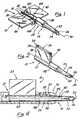
- Fig. 1is a front side view, in perspective, of an apparatus in accordance with the present invention with the load chamber in the opened position.
- Fig. 2is a front side view, in perspective, of the apparatus shown in Fig. 1 with the load chamber in the closed position.
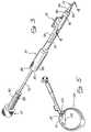
- Fig. 3is a front side view, in perspective, of the apparatus shown in Fig. 2 loaded into a hand piece.
- Fig. 4is a side view, partly in cross-section, taken generally along line 4-4 of Fig. 3.
- Fig. 5is a somewhat schematic illustration showing the apparatus shown in Fig. 3, with the hand piece partially in cross-section, being used to insert an IOL into an eye.
- Fig. 1shows an IOL inserter, shown generally at 10, including a load chamber 12 and an injection tube 14.
- Inserter 10is an integrally formed, for example, molded, unit made of polymeric material, such as polypropylene or the like materials.
- Load chamber 12includes a first member 16 and a second member 18 which are secured or joined together and are hingeably moveable relative to each other along line 20, which is parallel to the longitudinal axis 30 of inserter 10.
- Injection tube 14includes a proximal end portion 22, a distal end portion 24 and an open distal end 26.
- a reinforcing collar 28is coincidental with the proximal end portion 22 of injection tube 14.
- Open distal end 26is beveled at an angle of about 45° relative to the longitudinal axis 30 of the inserter 10.
- Injection tube 14includes a through slot 32 which extends from the open distal end 26 distally and terminates prior to the proximal end portion 22 of injection tube 14.
- Through slot 32is elongated in a direction parallel to the longitudinal axis 30 of inserter 10.
- inserter 10is in the opened position.
- inserter 10is shown in the closed position.
- the load chamber 12includes a top 33 which is a combination of top surfaces 34 and 36 of first wing 38 and second wing 40, respectively, of first member 16 and second member 18, respectively.
- First and second wings 38 and 40are effective for a human user of inserter 10 to hold and manipulate the inserter 10 while using it, as described hereinafter.
- Inserter 10is described in more detail with reference to Fig. 4, which shows the inserter in combination with hand piece 70.
- the load chamber 12 of inserter 10When used in combination with hand piece 70, the load chamber 12 of inserter 10 is in the closed position, as shown in Fig. 2. With the load chamber 12 in the closed position, and top 32 being the uppermost portion of the load chamber, open distal end 26 of injection tube 14 is beveled at an angle of 45° relative to the longitudinal axis 30 of the inserter 10 so that the open distal end is generally right facing (when the inserter is viewed from above). In addition, through slot 32 intersects the open distal end 26 at the proximal most portion of the open distal end, as shown in Figs. 1, 2 and 4.
- the load chamberdefines a first lumen 52 which is elongated in a direction parallel to the longitudinal axis 30 of inserter 10.
- Injection tube 14defines a distally tapering second lumen 54.
- the average cross-sectional area of second lumen 54 transverse to the longitudinal axis 30is smaller than or reduced relative to the average cross-sectional area of the first lumen 52.
- the reinforcing collar 28, which is coincidental with the proximal end portion 22 of injection tube 14,has sufficient wall thickness so that the proximal end portion of the injection tube has a larger or greater wall thickness than the distal end portion 24 of the injection tube.
- the first lumen 52is aligned with the second lumen 54 so that a folded IOL in the first lumen can be passed directly from the first lumen into the second lumen.
- the proximal portion 58 of the second lumen 54is defined by the proximal end portion 22 of the injection tube 14.
- This proximal portion 58 of second lumen 54has a tapering cross-sectional area transverse to the longitudinal axis 30 of the inserter 10, with the cross-sectional area decreasing in the distal direction.
- the taper of proximal portion 58is more severe than the slight taper which exists in the distal portion 60 of the second lumen 54.
- the more severe taper in the proximal portion 58is effective to further fold the IOL as the IOL is passed into the second lumen 54. This further folding is advantageous because the further folded IOL can be inserted into the eye through a smaller incision.
- the reinforcing collar 28 and the increased wall thickness of the proximal end portion 22 of injection tube 14adds
- Hand piece 70includes a relatively large, elongated first through opening 74 and a relatively small, elongated second through opening 76.
- Hand piece 70includes a through bore 78 which extends from the proximal end 80 to the distal end 82 of the hand piece.
- the proximal end portion 84 of hand piece 70includes threads 86 which are adapted to engage and mate with threads 88 of the proximal segment 90 of push rod member 72.
- Rod element 92 of push rod member 72is adapted to pass through bore 78, first lumen 52, second lumen 54 and out of open distal end 26.
- Hand piece 70 and push rod member 72are made of metal, such as surgical grade stainless steel or the like metals.
- Inserter 10is operated and functions as follows.
- the inserterWhen it is desired to load an IOL into inserter 10, the inserter is placed, for example, manually placed, in a configuration as shown in Fig. 1.
- an IOLsuch as is shown generally at 100, is placed, for example, using forceps, in between first and second members 16 and 18. This placement is such that the anterior face 102 of optic 104 faces upwardly, as shown in Fig. 1.
- the filament haptics 106 and 108 of IOL 100are located as shown in Fig. 1, so that the fixation members are located generally parallel to, rather than transverse to, the longitudinal axis 30.
- first and second members 16 and 18are hingeably moved relative to each other, for example, by manually bringing first and second wings 38 and 40 together, to place the load chamber 12 in the closed position, as shown in Fig. 2.
- load chamber 12With load chamber 12 in the closed position, IOL 100 is in a folded state, that is optic 104 is folded.
- the relative movement of first and second members 16 and 18 to move the load chamber from the open position to the closed positionis effective to fold the lens.
- the folded IOL 100is now located in the first lumen 52. For clarity sake, the folded IOL is not shown in any of Figs. 2, 3, 4 or 5.
- the inserter 10With the inserter 10 configured as shown in Fig. 2 and folded IOL 100 located in first lumen 52, the inserter 10 is placed in association with hand piece 70, as shown in Fig. 3. In this configuration, the distal end portion 24 of injection tube 14 extends distally beyond the distal end 82 of hand piece 70. As shown in Fig. 4, the distal portion 85 of hand piece 70 includes an inner wall 87 which is configured to receive reinforcing collar 28 in abutting relation.
- This abutting contact between hand piece 70 and reinforcing collar 28adds to the apparent strength of the injection tube 14 so that folded IOL 100 can be passed from the first lumen 52 into the second lumen 54 (so that the folded IOL 100 can be further folded so as to be inserted into the eye through a smaller incision), through the second lumen and out of the open distal end 26 without breaking, bursting or otherwise distorting the configuration of the injection tube.
- push rod member 72With inserter 10 so placed relative to hand piece 70, push rod member 72 is placed into the through bore 78 of the hand piece starting at the proximal end 80. As threads 88 come in contact with and engage threads 86, the push rod member 72 is rotated, as shown in Fig. 5, so as to thread the push rod member onto the proximal end portion 84 of hand piece 70. By gradually moving push rod element 92 through bore 78 of hand piece 70, the folded IOL 100 is urged to move from first lumen 52 into second lumen 56, through open distal end 26 and into the eye.
- the IOL 100is to be placed in eye 120 into an area formerly occupied by the natural lens of the eye.
- Fig. 5shows the sclera 122 having an incision through which the distal end portion 24 of injection tube 14 is passed. Alternately, the incision can be made through the cornea. Distal end portion 24 has a sufficiently small cross-section to pass into the eye 122 through a 3.0 mm incision in the sclera 122.
- the injection tube 14is manipulated within eye 122 until it is positioned so that IOL 100 can be properly positioned in eye 122, that is in the anterior chamber, the posterior chamber, the capsular bag 124 or in the sulcus, after being released.
- the surgeonis able to controllably position the distal end portion 24 of injection tube 14, with IOL 100 in the first lumen 52 of load chamber 12.
- the rod element 92is urged distally, by rotating (threading) push rod member 72 onto hand piece 70, to pass the IOL 100 into and through the second lumen 54, through the open distal end 26 of injection tube 14 and into the eye 120.
- the anterior face 102 of IOL 100faces generally forwardly in the eye 120 as the IOL is released from the inserter 10. In other words, the IOL 100 passes through first lumen 52, second lumen 54 and open distal end 26 and into eye 120 without flipping or otherwise becoming mispositioned. Only a relatively small amount of, if any, post-insertion re-positioning is needed to properly position IOL 100 in eye 120.
- the rod element 92is moved proximally into the injection tube 14 and the distal end portion 24 of the injection tube is removed from the eye. If needed, the IOL 100 can be re-positioned in the eye by a small, bent needle or similar tool inserted into the same incision.
- the use of the present insertion apparatusreduces or minimizes the need for post-insertion manipulation of IOL 100.
- the incision in the scleramay be mended, for example, using conventional techniques.
- inserter 10is preferably disposed of.
- Hand piece 70 and push rod member 72can be reused, after sterilization/disinfection.
- the present IOL insertion apparatus and methodsare straightforward and easy to use and practice.
- the present inventionprovides for an effective and controlled insertion of foldable IOLs into eyes.
- the present systemvery conveniently provides for precise positioning of the IOL in the eye and controlled IOL release so as to reduce, or even eliminate, the risk of damaging the eye as a result of IOL insertion or post surgical manipulation to properly position the IOL in the eye. It is to be understood that the invention is not limited thereto and that it can be variously practiced within the scope of the following claims.
Landscapes
- Health & Medical Sciences (AREA)
- Ophthalmology & Optometry (AREA)
- Cardiology (AREA)
- Oral & Maxillofacial Surgery (AREA)
- Transplantation (AREA)
- Engineering & Computer Science (AREA)
- Biomedical Technology (AREA)
- Heart & Thoracic Surgery (AREA)
- Vascular Medicine (AREA)
- Life Sciences & Earth Sciences (AREA)
- Animal Behavior & Ethology (AREA)
- General Health & Medical Sciences (AREA)
- Public Health (AREA)
- Veterinary Medicine (AREA)
- Prostheses (AREA)
Description
- This invention relates to apparatus for inserting afoldable intraocular lens (IOL) into the eye of a patient.
- As is well known, an IOL is used to replace thenatural lens of the human eye when the natural lensbecomes incapable of functioning as desired. A typicalIOL includes an optic or lens and one or more fixationmembers for fixing the IOL in the desired positionwithin the eye.
- The optic of an IOL may be constructed of hard,nondeformable materials such as polymethylmethacrylateor of soft, deformable materials such as silicone basedor acrylic based materials. One advantage of thedeformable IOL's is that they can be deformed into aconfiguration which permits them to be inserted througha smaller incision into the eye.
- In deforming the IOL, the optic is typicallyfolded in a way to cause the IOL to have smallerdimensions which enables it to be inserted through asmaller incision. An IOL which is deformed by formingit into a roll is also folded in the sense that theroll constitutes at least one fold. As used herein, afolded optic, folded IOL and folded condition havereference to an optic which is deformed in any manner,including rolling, that produces a fold.
- It is desirable to compactly fold a foldable IOLbecause this can minimize the length of the incisionnecessary to insert the folded IOL into the eye.However, because IOL's are very small, they aredifficult to grasp and even more difficult to fold intoan efficient, compact configuration of minimaldimensions. As an example of size, the optic of afoldable IOL may be in the neighborhood of about 5 toabout 7 millimeters in diameter.
- Various devices have been proposed for use ininserting a foldable IOL. For example, Bartell U.S.Patent 4,681,102 discloses a hingeably moveablecartridge which effectively facilitates the folding ofa foldable IOL for insertion into the eye. In oneuseful embodiment of such an apparatus, the cartridgeincludes an elongated injection tube having an opendistal end. The elongated injection tube receives thefolded IOL from the hingeably movably portion of thecartridge. The IOL is passed out of the open distalend into the eye. Although such an insertion system isgenerally very effective, further enhancements, forexample, in the apparent strength of the insertionsystem and in the ability of the system to control therelease of the IOL into the eye, would be advantageous.
- WO94/07436 discloses an intraocular lens insertion system.This document discloses a surgical device for implantationof a deformable intraocular lens into the eye through arelatively small incision made in the ocular tissueincluding a holder with receiver for a lens holder. Theholder has a split tubular member having a fixed tubularportion and a moveable tubular portion connected togetherat a hinge.
- WO94/20027 discloses apparatus and a method for preparingan intraocular lens for insertion. The apparatus has anelongated compression chamber with a longitudinalpassageway, having an inner surface. A portion of thepassageway adjacent to the proximal end of the chamber forms a loading area in which the passageway graduallydecreases in size for causing an intraocular lens to bedeformed or compressed as the lens is moved along thepassageway. A portion of the passageway is sized to retainthe lens in the deformed or compressed condition. Thepassageway includes an opening and a slot or groove forpermitting easy withdrawal of forceps used for pushing theIOL through the loading area.
- US 5190552 discloses a slotted tube injector for anintraocular lens. The injector is formed of a slotted tubeand is partially inserted via its front end into a minimumsize eye incision to inject a temporarily folded intraocularlens having opposed haptics extending from its periphery,into the eye without stressing the incision. Holding andlocking mechanisms serve to fold the lens into the tube rearend with the haptics protruding from the tube slot so as notto be jammed in the tube, and to unfold the lens out of thetube front end in the eye for release, all in a controlledmanner, and so as to avoid patient trauma from stress on theincision or contact of the unfolding lens with the innerwall of the cornea or other eye parts.
- New apparatus for surgically inserting a foldable IOLinto an eye have been discovered. The present apparatushave sufficient strength and/or are sufficiently reinforcedto insert a relatively tightly folded IOL through a smallincision in the eye without breaking or bending, even thoughthe injection portion or tube of the apparatus is made ofpolymeric material. In addition, the present apparatusallows the IOL to be released into the eye in a uniform andcontrolled manner, while reducing the risk that the IOL maybecome mispositioned, for example, flipped, during this insertion procedure. Thus, the need for post-insertionmanipulation of the IOL in the eye isadvantageously reduced. Moreover, the IOL may beloaded into the present apparatus very speedily andreliably. The present apparatus are straightforward inconstruction and can be produced and used in a numberof forms to suit the individual needs of the surgicalapplication involved and/or the likes and dislikes ofthe surgeon. The invention allows a surgeon to easilyand controllably place an IOL into a patient's eyethrough a small incision.
- In one broad aspect, the present invention isdirected to inserters for inserting a foldable IOL intoan eye of a patient. The inserters comprise a loadchamber defining a first lumen, an injection portion ortube defining a second lumen aligned with the firstlumen, and a hand piece adapted to be held in the handof a human using the inserter to insert an IOL into aneye. The load chamber is adapted to receive an IOL andto maintain the IOL. in a folded state when the IOL islocated in the first lumen. The injection tube has aproximal end portion, a distal end portion and an opendistal end in communication with the second lumen, andis adapted to receive the folded IOL from the firstlumen. The hand piece includes a bore having anopening adapted to receive the load chamber so that theproximal end portion of the- injection tube is inreinforcing contact with the hand piece, preferably inabutting relation to the wall of the bore of thehandpiece. The distal end portion of the injectiontube extends distally of the hand piece. Using a handpiece which is in reinforcing contact with the proximalend portion of the injection tube enhances the apparentstrength of the injection tube. Thus, even though theinjection tube is made of a polymeric material, as ispreferred, the injection tube has sufficient apparentor reinforced strength to pass a relatively tightly folded IOL through the second lumen thereof and into asmall incision in the eye without the injection tubebreaking, bursting, or otherwise being distorted inconfiguration. This adds greatly to the usefulness andreliability of the present apparatus.
- The load chamber and injection tube are preferablymade of polymeric material, while the hand piece ispreferably made of a metal.
- The second lumen, defined by the injection tube,preferably has a smaller average cross-sectional areathan does the first lumen. The proximal end portionof the injection tube has a wall thickness which isgreater than the wall thickness of the distal endportion. This increased wall thickness is effective toadd further additional strength to the injection tube.The distal end portion of the injection tube can havea relatively thin wall thickness so that it can beinserted into the eye through a small incision, forexample, an incision of about 3.2 or about 3.0 or about2.8 mm or less. The open distal end of the injectiontube is such that the folded IOL from the second lumenpasses through it to be inserted into the eye.
- In one embodiment, the present inserters includea push rod sized and adapted to be passed through thebore of the hand piece, the first lumen of the loadchamber and at least a portion of the second lumen ofthe injection tube to facilitate or urge the passage ofan IOL from the first lumen through the second lumenand into an eye. In a particularly useful embodiment,the hand piece and push rod include segments withmutually engageable threads so that the push rod can bethreaded onto the hand piece to pass the push rodthrough the bore of the hand piece. This threadedembodiment is very effective in controlling themovement of the folded IOL through the first and secondlumens and into the eye.
- In an embodiment of the invention, thepresent IOL inserters comprise a load chamber having atop, defining a first lumen and being adapted toreceive an IOL and to maintain the IOL in a foldedstate when the IOL is located in the first lumen; andan injection tube which defines a second lumen alignedwith the first lumen and is adapted to receive thefolded IOL from the first lumen. The injection tubehas a proximal end portion, a distal end portion and anopen distal end in communication with the second lumenand through which the folded IOL from the second lumenpasses to be inserted into the eye. In this aspect ofthe invention, the open distal end of the injectiontube is beveled, preferably so that the open distal endfaces generally toward the right when the topof theload chamber is positioned to be the uppermost portionof the load chamber and the inserter is viewed fromabove. The beveling of the distal end opening iseffective to reduce the size of the incision in the eyethrough which the distal end portion of the injectiontube can pass relative to a substantially identical(for example, in cross-sectioned area) injection tubeincluding a distal end opening which is not beveled.The generally right facing beveled distal end opening,described herein, facilitates the passing of the IOLfrom the second lumen through the open distal end sothat the IOL is released in the eye in a uniform andcontrolled manner, for example, with reduced risk ofthe IOL becoming mispositioned, e.g. flipped, duringinsertion into the eye. Using such an inserter, theIOL can be controllably and uniformly released into theeye in the desired position so that a reduced amount ofmanipulation of the IOL is required to properly placethe IOL in the eye. As noted above, this isadvantageous to avoid additional trauma to the eyecaused by such post-insertion manipulation.
- The beveled distal end opening can be employedalone or in combination with the previously describedhand piece in reinforcing contact with the injectiontube. In addition, unless expressly stated otherwiseor unless two or more features are mutuallyinconsistent, each of the features described herein canbe used in combination with any one or more of theother features described herein, and all such apparatusare within the scope of the presentinvention.
- As noted above, the open distal end of theinjection tube is preferably beveled, more preferablyat an angle of about 30° to about 60° and still morepreferably at an angle of about 45°, relative to thelongitudinal axis of the inserter. Such beveling hasbeen found to advantageously reduce the minimum size ofincision through which the distal end portion of theinjection tube can be passed relative to asubstantially identical injection tube including anopen distal end which is not beveled.
- In a particularly useful embodiment, the injectiontube further comprises a through slot which extendsfrom the open distal end of the injection tube andterminates distally of the proximal end portion of theinjection tube. This through slot is effective toallow for some flexibility in the distal end portion ofthe injection tube so that a smaller incision in theeye may be utilized for insertion of the IOL. Thelength of the through slot is preferably such as toprovide such advantageous degree of flexibility while,at the same time, not compromising the integrity of theinjection tube so that the configuration and structuralintegrity of the injection tube is substantiallymaintained. In addition, the width of the through slotis preferably such that the fixation member or membersof the IOL do not stick in or grab onto the throughslot. Thus, the through slot is preferably configured so that the fixation member or members are passedthrough the second lumen and into the eye withoutgrabbing onto the through slot. The through slot ispreferably elongated in a direction substantiallyparallel to the longitudinal axis of the inserter. Ina useful embodiment, with the distal end opening of theinjection tube being beveled, the through slotintersects the open distal end at or near the proximalmost portion of the open distal end.
- The combination of a beveled open distal end,preferably a generally right facing beveled open distalend, and the through slot of the injection tubeenhances the controllability of releasing the IOL intothe. eye. An inserter system including thiscombination of features has been found to reduce therisk that the IOL will become mispositioned in theinserter. Thus, the IOL is advantageously released inthe eye in the desired position or orientation so thata reduced amount of post-insertion manipulation of theIOL is required.
- In one embodiment of the invention, the inserterfurther comprises a holding element, preferablyextending from the top of the load chamber, sized andadapted to be held in the hand of a human user of theinserter. This holding element is effective, forexample, in placing the load chamber into the handpiece.
- In a very useful embodiment, the load chambercomprises first and second members which are moveable,preferably hingeably moveable, relative to each otherto place the load chamber in an opened position or ina closed position. The first and second members arepreferably sized and adapted to receive an IOL in anunfolded state between the first and second memberswhen the load chamber is in the opened position. Thefirst and second members are sized and adapted to foldthe IOL into a folded state as at least one of the first and second members are moved to place the loadchamber in the closed position. In the closedposition, the first and second members together defineat least a portion of the first lumen of the loadchamber.
- The invention allows an IOL to be insertedinto a small incision in the eye. In general,methods of insertion comprise placing an IOL in aninserter as described herein; placing the open distalend of the injection tube at least partially into aneye; and causing the IOL to pass out of the open distalend of the injection tube and into the eye. In theevent the load chamber includes first and secondmembers, as described. herein, the IOL is placed in theinserter so that the IOL in an unfolded state islocated between the first and second members with theload chamber in the opened position. At least one ofthe first and second members is moved so as to placethe load chamber in the closed position, therebyfolding the IOL into a folded state. The open distalend of the injection tube is placed at partially intoan eye and the folded IOL is caused to pass out of theopen distal end of the injection tube and into the eye.
- The foldable IOL's insertable in the eye using thepresent apparatus may be of anyconfiguration suitable to perform the desired functionin the eye. Such lenses often include a lens body oroptic which has optical properties in the eye. Suchlens body is foldable as set forth herein. In manyinstances, the lens body is generally circular.However, other configurations are also useful. Inaddition, the IOL's may, and preferably do, include atleast one flexible fixation member which is secured orattached to the optic. This flexible fixation memberacts to fix the IOL in position in the eye. Examplesof flexible fixation members include flexible haptics which are preferably radially resilient and extendoutwardly from the periphery of the lens body.Specific examples of such flexible haptics includeplate haptics and those commonly known as J-loops andC-loops. Such haptics engage appropriatecircumferential eye tissue adjacent the iris or withinthe capsular bag to fix the lens in position in theeye. A very useful IOL includes a plurality of,especially two, such flexible haptics.
- The lens body may be made of any suitable materialsuch as acrylic polymers, silicone polymers, hydrogel-formingpolymers or other well known materials forfoldable IOL instruction. The present inserter systemsare. particularly effective with IOLs having opticsincluding silicone polymers. Preferably, the opticalso includes an ultraviolet light absorber. Theflexible fixation member or members may be made of anysuitable material such as polymethamethacrylate,polypropylene, nylon, silicone polymers or othermaterials suitable for implantation into the eye.
- As used herein, the terms "foldable" and"deformable" mean that an IOL, and in particular thelens body or optic of an IOL, can be temporarilyreshaped so as to pass through a smaller incisionrelative to the incision required if the IOL was nottemporarily reshaped.
- These and other aspects and advantages of thepresent invention are set forth in the followingdetailed description and claims, particularly whenconsidered in conjunction with the accompanyingdrawings in which like parts bear like referencenumerals.
- Fig. 1 is a front side view, in perspective, of anapparatus in accordance with the present invention withthe load chamber in the opened position.
- Fig. 2 is a front side view, in perspective, ofthe apparatus shown in Fig. 1 with the load chamber inthe closed position.
- Fig. 3 is a front side view, in perspective, ofthe apparatus shown in Fig. 2 loaded into a hand piece.
- Fig. 4 is a side view, partly in cross-section,taken generally along line 4-4 of Fig. 3.
- Fig. 5 is a somewhat schematic illustrationshowing the apparatus shown in Fig. 3, with the handpiece partially in cross-section, being used to insertan IOL into an eye.
- Fig. 1 shows an IOL inserter, shown generally at10, including a
load chamber 12 and aninjection tube 14.Inserter 10 is an integrally formed, for example,molded, unit made of polymeric material, such aspolypropylene or the like materials.Load chamber 12includes afirst member 16 and asecond member 18 whichare secured or joined together and are hingeablymoveable relative to each other alongline 20, which isparallel to thelongitudinal axis 30 ofinserter 10. Injection tube 14 includes aproximal end portion 22, adistal end portion 24 and an opendistal end 26.A reinforcingcollar 28 is coincidental with theproximal end portion 22 ofinjection tube 14.- Open
distal end 26 is beveled at an angle of about45° relative to thelongitudinal axis 30 of theinserter 10. Injection tube 14 includes a throughslot 32 whichextends from the opendistal end 26 distally andterminates prior to theproximal end portion 22 ofinjection tube 14. Throughslot 32 is elongated in adirection parallel to thelongitudinal axis 30 ofinserter 10.- As shown in Fig. 1,
inserter 10 is in the openedposition. In contrast, in Fig. 2,inserter 10 is shown in the closed position. In the closed position, theload chamber 12 includes a top 33 which is acombination oftop surfaces first wing 38andsecond wing 40, respectively, offirst member 16andsecond member 18, respectively. First andsecondwings inserter 10 to hold and manipulate theinserter 10while using it, as described hereinafter. Inserter 10 is described in more detail withreference to Fig. 4, which shows the inserter incombination withhand piece 70. When used incombination withhand piece 70, theload chamber 12 ofinserter 10 is in the closed position, as shown in Fig.2. With theload chamber 12 in the closed position,and top 32 being the uppermost portion of the loadchamber, opendistal end 26 ofinjection tube 14 isbeveled at an angle of 45° relative to thelongitudinalaxis 30 of theinserter 10 so that the open distal endis generally right facing (when the inserter is viewedfrom above). In addition, throughslot 32 intersectsthe opendistal end 26 at the proximal most portion ofthe open distal end, as shown in Figs. 1, 2 and 4.- Referring to Fig. 4, with
load chamber 12 in theclosed position, the load chamber defines afirst lumen 52 which is elongated in a direction parallel to thelongitudinal axis 30 ofinserter 10.Injection tube 14defines a distally taperingsecond lumen 54. Theaverage cross-sectional area ofsecond lumen 54transverse to thelongitudinal axis 30 is smaller thanor reduced relative to the average cross-sectional areaof thefirst lumen 52. The reinforcingcollar 28,which is coincidental with theproximal end portion 22ofinjection tube 14, has sufficient wall thickness sothat the proximal end portion of the injection tube hasa larger or greater wall thickness than thedistal endportion 24 of the injection tube. - The
first lumen 52 is aligned with thesecondlumen 54 so that a folded IOL in the first lumen can bepassed directly from the first lumen into the secondlumen. Theproximal portion 58 of thesecond lumen 54is defined by theproximal end portion 22 of theinjection tube 14. Thisproximal portion 58 ofsecondlumen 54 has a tapering cross-sectional area transverseto thelongitudinal axis 30 of theinserter 10, withthe cross-sectional area decreasing in the distaldirection. The taper ofproximal portion 58 is moresevere than the slight taper which exists in thedistalportion 60 of thesecond lumen 54. The more severetaper in theproximal portion 58 is effective tofurther fold the IOL as the IOL is passed into thesecond lumen 54. This further folding is advantageousbecause the further folded IOL can be inserted into theeye through a smaller incision. The reinforcingcollar 28 and the increased wall thickness of theproximal endportion 22 ofinjection tube 14 adds to the apparentstrength of the injection tube. - With reference to Fig. 3,
inserter 10 is shown incombination withhand piece 70 and pushrod member 72.Hand piece 70 includes a relatively large, elongatedfirst throughopening 74 and a relatively small,elongated second throughopening 76.Hand piece 70includes a throughbore 78 which extends from theproximal end 80 to thedistal end 82 of the hand piece.Theproximal end portion 84 ofhand piece 70 includesthreads 86 which are adapted to engage and mate withthreads 88 of theproximal segment 90 ofpush rodmember 72.Rod element 92 ofpush rod member 72 isadapted to pass through bore 78,first lumen 52,secondlumen 54 and out of opendistal end 26.Hand piece 70and pushrod member 72 are made of metal, such assurgical grade stainless steel or the like metals. Inserter 10 is operated and functions as follows.When it is desired to load an IOL intoinserter 10, the inserter is placed, for example, manually placed, in aconfiguration as shown in Fig. 1. Withload chamber 12in the opened position, an IOL, such as is showngenerally at 100, is placed, for example, usingforceps, in between first andsecond members anterior face 102 ofoptic 104 faces upwardly, as shown in Fig. 1. Thefilament haptics IOL 100 are located asshown in Fig. 1, so that the fixation members arelocated generally parallel to, rather than transverseto, thelongitudinal axis 30.- With
IOL 100 placed as shown in Fig. 1, first andsecond members second wings loadchamber 12 in the closed position, as shown in Fig. 2.Withload chamber 12 in the closed position,IOL 100 isin a folded state, that is optic 104 is folded. Therelative movement of first andsecond members IOL 100 is now located in thefirst lumen 52.For clarity sake, the folded IOL is not shown in any ofFigs. 2, 3, 4 or 5. - With the
inserter 10 configured as shown in Fig.2 and foldedIOL 100 located infirst lumen 52, theinserter 10 is placed in association withhand piece 70, as shown in Fig. 3. In this configuration, thedistal end portion 24 ofinjection tube 14 extendsdistally beyond thedistal end 82 ofhand piece 70. Asshown in Fig. 4, thedistal portion 85 ofhand piece 70includes aninner wall 87 which is configured toreceive reinforcingcollar 28 in abutting relation.This abutting contact betweenhand piece 70 andreinforcingcollar 28 adds to the apparent strength oftheinjection tube 14 so that foldedIOL 100 can bepassed from thefirst lumen 52 into the second lumen 54 (so that the foldedIOL 100 can be further folded so asto be inserted into the eye through a smallerincision), through the second lumen and out of the opendistal end 26 without breaking, bursting or otherwisedistorting the configuration of the injection tube. - With
inserter 10 so placed relative tohand piece 70,push rod member 72 is placed into the throughbore 78 of the hand piece starting at theproximal end 80.Asthreads 88 come in contact with and engagethreads 86, thepush rod member 72 is rotated, as shown in Fig.5, so as to thread the push rod member onto theproximal end portion 84 ofhand piece 70. By graduallymovingpush rod element 92 throughbore 78 ofhandpiece 70, the foldedIOL 100 is urged to move fromfirst lumen 52 into second lumen 56, through opendistal end 26 and into the eye. - Referring now to Fig. 5, the
IOL 100 is to beplaced ineye 120 into an area formerly occupied by thenatural lens of the eye. Fig. 5 shows thesclera 122having an incision through which thedistal end portion 24 ofinjection tube 14 is passed. Alternately, theincision can be made through the cornea.Distal endportion 24 has a sufficiently small cross-section topass into theeye 122 through a 3.0 mm incision in thesclera 122. - The
injection tube 14 is manipulated withineye 122 until it is positioned so thatIOL 100 can beproperly positioned ineye 122, that is in the anteriorchamber, the posterior chamber, thecapsular bag 124 orin the sulcus, after being released. Thus, the surgeonis able to controllably position thedistal end portion 24 ofinjection tube 14, withIOL 100 in thefirstlumen 52 ofload chamber 12. Oncedistal end portion 24 is so positioned, therod element 92 is urgeddistally, by rotating (threading)push rod member 72ontohand piece 70, to pass theIOL 100 into andthrough thesecond lumen 54, through the opendistal end 26 ofinjection tube 14 and into theeye 120. Theanterior face 102 ofIOL 100 faces generally forwardlyin theeye 120 as the IOL is released from theinserter 10. In other words, theIOL 100 passes throughfirstlumen 52,second lumen 54 and opendistal end 26 andintoeye 120 without flipping or otherwise becomingmispositioned. Only a relatively small amount of, ifany, post-insertion re-positioning is needed toproperly positionIOL 100 ineye 120. - After the
IOL 100 has been inserted into the eye,therod element 92 is moved proximally into theinjection tube 14 and thedistal end portion 24 of theinjection tube is removed from the eye. If needed, theIOL 100 can be re-positioned in the eye by a small,bent needle or similar tool inserted into the sameincision. The use of the present insertion apparatusreduces or minimizes the need for post-insertionmanipulation ofIOL 100. - Once the
IOL 100 is properly positioned ineye 120andinserter 10 is withdrawn from the eye, the incisionin the sclera may be mended, for example, usingconventional techniques. After use,inserter 10 ispreferably disposed of.Hand piece 70 and pushrodmember 72 can be reused, aftersterilization/disinfection. - The present IOL insertion apparatus and methodsare straightforward and easy to use and practice. Thepresent invention provides for an effective andcontrolled insertion of foldable IOLs into eyes. Thepresent system very conveniently provides for precisepositioning of the IOL in the eye and controlled IOLrelease so as to reduce, or even eliminate, the risk ofdamaging the eye as a result of IOL insertion or postsurgical manipulation to properly position the IOL inthe eye. it is to be understood that the invention is notlimited thereto and that it can be variously practicedwithin the scope of the following claims.
Claims (9)
- An inserter (10) for inserting a foldable intraocular lens (100) into aneye (120) of a patient comprising:wherein said proximal end portion (22) of said injection tube (14)is in abutting relation to said hand piece (70), and wherein said abuttingrelation acts as a stop for forward movement of the proximal end portion (22)in the distal direction.a load chamber (12) defining a first lumen (52) and beingadapted to receive an intraocular lens, and to maintain the intraocular lens(100) in a folded state when the intraocular lens (100) is located in said firstlumen (52);an injection tube (14) defining a second lumen (54) aligned withsaid first lumen (52), and being adapted to receive the folded intraocular lens(100) from said first lumen (52), said injection tube (14) having a proximalend portion (22) having a wall thickness, a distal end portion (24) having awall thickness and an open distal end in communication with said lumen (54)and through which the folded intraocular lens (100) from said second lumen(54) passes to be inserted into an eye, the wall thickness of the proximal endportion (22) being greater than the wall thickness of the distal end portion(24);a hand piece, (70) adapted to be held in the hand of a humanusing said inserter (10) to insert an intraocular lens (100) into an eye, saidhand piece (70) including a bore (78) having an opening adapted to receivesaid load chamber (12),characterised in that said proximal end portion (22) ofsaid injection tube (14) is entirely within and in reinforcing contact with saidhand piece (70) and a portion of said distal end portion (24) of said injectiontube (14) is located within the hand piece (70) and another portion extendsdistally from said hand piece (70);
- The inserter (10) of Claim 1, wherein said second lumen (54) has asmaller average cross-sectional area than said first lumen (52).
- The inserter (10) of Claim 1, wherein said load chamber (12) and saidinjection tube (14) are made of polymeric material and said hand piece (70) is made of metal; and which further comprises a push rod (72) sized andadapted to be passed through said bore (78), said first lumen (52) and atleast a portion of said second lumen (54) to facilitate the passage of anintraocular lens (100) for said first lumen (52) through said second lumen (54)and into an eye (120).
- The inserter (10) of Claim 3, wherein said hand piece (70) and push rod(72) include segments with mutually engageable threads (86, 88) so that saidpush rod (72) can be threaded onto said hand piece (70) to pass said pushrod (72) through said bore (78).
- The inserter (10) of Claim 1, wherein said open distal end (26) isbevelled.
- The inserter (10) of Claim 5, wherein said load chamber (12) has a top(33) and said open distal end (26) is bevelled so that said open distal end (26)faces generally toward the right when viewed from above the top (33) withsaid distal end portion (24) extending distally away.
- The inserter (10) of Claim 5, wherein said injection tube (14) furthercomprises a through slot (32) which extends to said open distal end (26),terminates distally of said proximal end portion (22) of said injection tube(14), and intersects said open distal end (26) at or near the proximal mostportion of said open distal end (26).
- The inserter (10) of Claim 1, wherein said load chamber (12) comprisesfirst and second members (16, 18) which are moveable relative to each otherto place said load chamber (12) in an opened position or in a closed position,and said first and second members (16, 18) are sized and adapted to receivean intraocular lens (100) in an unfolded state between said first and secondmembers (16, 18) when said load chamber (12) is in the opened position andto fold the intraocular lens (100) into a folded state as at least one of said firstand second members (16, 18) is moved to place said load chamber (12) in theclosed position.
- The inserter (10) of Claim 8, wherein said first and second members(16, 18) are hingeably moveable relative to each other.
Applications Claiming Priority (3)
| Application Number | Priority Date | Filing Date | Title |
|---|---|---|---|
| US08/323,172US5582613A (en) | 1993-11-18 | 1994-10-14 | Apparatus and methods for controlled insertion of intraocular lenses |
| US323172 | 1994-10-14 | ||
| EP95935715AEP0785760B1 (en) | 1994-10-14 | 1995-10-14 | Apparatus for controlled insertion of intraocular lenses |
Related Parent Applications (1)
| Application Number | Title | Priority Date | Filing Date |
|---|---|---|---|
| EP95935715ADivisionEP0785760B1 (en) | 1994-10-14 | 1995-10-14 | Apparatus for controlled insertion of intraocular lenses |
Publications (2)
| Publication Number | Publication Date |
|---|---|
| EP1023880A1 EP1023880A1 (en) | 2000-08-02 |
| EP1023880B1true EP1023880B1 (en) | 2003-10-01 |
Family
ID=23258027
Family Applications (2)
| Application Number | Title | Priority Date | Filing Date |
|---|---|---|---|
| EP00201469AExpired - LifetimeEP1023880B1 (en) | 1994-10-14 | 1995-10-14 | Apparatus for controlled insertion of intraocular lenses |
| EP95935715AExpired - LifetimeEP0785760B1 (en) | 1994-10-14 | 1995-10-14 | Apparatus for controlled insertion of intraocular lenses |
Family Applications After (1)
| Application Number | Title | Priority Date | Filing Date |
|---|---|---|---|
| EP95935715AExpired - LifetimeEP0785760B1 (en) | 1994-10-14 | 1995-10-14 | Apparatus for controlled insertion of intraocular lenses |
Country Status (6)
| Country | Link |
|---|---|
| US (1) | US5582613A (en) |
| EP (2) | EP1023880B1 (en) |
| JP (1) | JPH10512460A (en) |
| AU (1) | AU3762995A (en) |
| DE (2) | DE69531878T2 (en) |
| WO (1) | WO1996011649A1 (en) |
Cited By (2)
| Publication number | Priority date | Publication date | Assignee | Title |
|---|---|---|---|---|
| US7901414B2 (en) | 2001-12-12 | 2011-03-08 | Ioltechnologie-Production | Cassette and injector for flexible intraocular lens and method for injecting such lenses |
| US10722346B2 (en) | 2017-09-19 | 2020-07-28 | Bausch & Lomb Incorporated | Intraocular lens injector assembly having shuttle assembly retaining intraocular lens in storage vial and operably presenting intraocular lens in injector assembly |
Families Citing this family (65)
| Publication number | Priority date | Publication date | Assignee | Title |
|---|---|---|---|---|
| DE69331807T2 (en)* | 1992-09-30 | 2002-09-26 | Vladimir Feingold | INTRAOCULAR LENS INSERTION SYSTEM |
| US5653715A (en) | 1993-03-09 | 1997-08-05 | Chiron Vision Corporation | Apparatus for preparing an intraocular lens for insertion |
| CN1143313A (en)* | 1994-11-18 | 1997-02-19 | 弗拉基米尔·法因戈尔德 | Disposable intraocular lens insertion system |
| US5766181A (en)* | 1996-08-02 | 1998-06-16 | Staar Surgical Company, Inc. | Spring biased deformable intraocular injecting apparatus |
| US5876406A (en)* | 1996-08-02 | 1999-03-02 | Staar Surgical Company, Inc. | Deformable intraocular lens injecting apparatus with transverse hinged lens cartridge |
| US5944725A (en)* | 1996-09-26 | 1999-08-31 | Bausch & Lomb Surgical, Inc. | Method and apparatus for inserting a flexible membrane into an eye |
| US6179843B1 (en) | 1997-06-28 | 2001-01-30 | Harold H. Weiler | Device for insertion of foldable intraocular lenses |
| US6605093B1 (en) | 1997-10-24 | 2003-08-12 | Tekia, Inc. | Device and method for use with an ophthalmologic insertor apparatus |
| AU7361898A (en) | 1997-10-24 | 1999-05-17 | Tekia, Inc. | Ophthalmologic insertor apparatus and methods of use |
| US5921989A (en)* | 1998-02-12 | 1999-07-13 | Allergan | Lens protector for intraocular lens inserter |
| US6371960B2 (en) | 1998-05-19 | 2002-04-16 | Bausch & Lomb Surgical, Inc. | Device for inserting a flexible intraocular lens |
| FR2820633B1 (en)* | 2001-02-13 | 2003-08-15 | Biotech | INTRAOCULAR LENS INJECTION DEVICE AND METHOD |
| WO2003044946A2 (en)* | 2001-10-12 | 2003-05-30 | Humanoptics Ag | Device for folding an intraocular lens and system for storing an intraocular lens |
| DE10164420A1 (en)* | 2001-10-12 | 2003-07-17 | Humanoptics Ag | Device for folding an intraocular lens and storage system for an intraocular lens |
| US20040059343A1 (en)* | 2002-09-25 | 2004-03-25 | Kevin Shearer | Novel enhanced system for intraocular lens insertion |
| US20040147938A1 (en)* | 2002-09-25 | 2004-07-29 | Microsurgical Technology | System for IOL insertion |
| DE202004017931U1 (en) | 2004-08-12 | 2005-01-13 | Medicel Ag | Device for loading a lens folding cartridge with an intraocular lens, as well as lens folding cartridge and set for implantation |
| US20060085013A1 (en)* | 2004-10-20 | 2006-04-20 | Vaclav Dusek | Intraocular lens inserter |
| EP1832247B1 (en) | 2004-12-27 | 2015-06-24 | Hoya Corporation | Intraocular lens implanting device |
| US20060167466A1 (en)* | 2005-01-21 | 2006-07-27 | Vaclav Dusek | Intraocular lens inserter system components |
| EP1849436B1 (en) | 2005-01-26 | 2017-11-01 | Hoya Corporation | Intraocular lens insertion device |
| JP4836046B2 (en) | 2005-02-24 | 2011-12-14 | Hoya株式会社 | Intraocular lens insertion device |
| US7892282B2 (en)* | 2005-04-08 | 2011-02-22 | Abbott Medical Optics Inc. | Methods and apparatus for inserting an intraocular lens into an eye |
| US7892283B2 (en)* | 2005-04-08 | 2011-02-22 | Abbott Medical Optics Inc. | Methods and apparatus for inserting an intraocular lens into an eye |
| US8053078B2 (en) | 2005-04-11 | 2011-11-08 | Abbott Medical Optics Inc. | Medical devices having soft, flexible lubricious coatings |
| US8574239B2 (en) | 2005-09-28 | 2013-11-05 | Hoya Corporation | Intraocular lens insertion device |
| US20070078466A1 (en)* | 2005-09-30 | 2007-04-05 | Restoration Robotics, Inc. | Methods for harvesting follicular units using an automated system |
| JP4877643B2 (en) | 2005-12-08 | 2012-02-15 | Hoya株式会社 | Intraocular lens insertion device |
| EP2111820A1 (en) | 2007-01-17 | 2009-10-28 | Ajl, S.a. | Container for an intraocular lens and method for applying an intraocular lens |
| US20080255577A1 (en)* | 2007-04-11 | 2008-10-16 | Downer David A | Lens Delivery System Cartridge and Method of Manufacture |
| JP5236638B2 (en) | 2007-05-30 | 2013-07-17 | Hoya株式会社 | Intraocular lens insertion device |
| US8475528B2 (en) | 2007-05-30 | 2013-07-02 | Hoya Corporation | Intraocular lens insertion device |
| JP5086713B2 (en) | 2007-07-11 | 2012-11-28 | Hoya株式会社 | Intraocular lens insertion device |
| US8956408B2 (en) | 2007-07-23 | 2015-02-17 | Powervision, Inc. | Lens delivery system |
| US8968396B2 (en) | 2007-07-23 | 2015-03-03 | Powervision, Inc. | Intraocular lens delivery systems and methods of use |
| US8668734B2 (en) | 2010-07-09 | 2014-03-11 | Powervision, Inc. | Intraocular lens delivery devices and methods of use |
| JP5330401B2 (en) | 2007-11-08 | 2013-10-30 | アリメラ・サイエンシーズ,インコーポレーテッド | Implant device for the eye and kit comprising the device |
| USD592746S1 (en) | 2007-11-08 | 2009-05-19 | Alimera Sciences | Ocular implantation device |
| KR101264267B1 (en) | 2008-02-07 | 2013-05-22 | 알콘, 인코퍼레이티드 | lens delivery system cartridge |
| JP5254669B2 (en) | 2008-06-05 | 2013-08-07 | Hoya株式会社 | Intraocular lens insertion device and cartridge |
| JP5470753B2 (en) | 2008-06-17 | 2014-04-16 | Hoya株式会社 | Intraocular lens insertion device |
| JP5323420B2 (en) | 2008-08-21 | 2013-10-23 | Hoya株式会社 | Intraocular lens insertion device |
| JP5416379B2 (en) | 2008-09-04 | 2014-02-12 | Hoya株式会社 | Intraocular lens insertion device |
| US8801780B2 (en) | 2008-10-13 | 2014-08-12 | Alcon Research, Ltd. | Plunger tip coupling device for intraocular lens injector |
| SG172876A1 (en) | 2009-01-07 | 2011-08-29 | Hoya Corp | Intraocular lens insertion device |
| US9421092B2 (en) | 2009-02-11 | 2016-08-23 | Alcon Research, Ltd. | Automated intraocular lens injector device |
| JP5735531B2 (en) | 2010-04-08 | 2015-06-17 | Hoya株式会社 | Ocular graft insertion device |
| JP5511530B2 (en) | 2010-06-10 | 2014-06-04 | Hoya株式会社 | Intraocular lens insertion device |
| EP2688515B1 (en) | 2011-03-24 | 2021-05-19 | Alcon Inc. | Intraocular lens loading systems and methods of use |
| ES2610198T3 (en) | 2012-06-04 | 2017-04-26 | Alcon Pharmaceuticals Ltd. | Intraocular lens insertion device and method for unloading an intraocular lens from a cartridge |
| CN108420598B (en) | 2012-06-12 | 2021-03-09 | 爱尔康公司 | Hand-held gas mixer and injector assembly, hand-held gas injector device and method of mixing gas |
| EP3785668A1 (en) | 2013-03-15 | 2021-03-03 | Alcon Inc. | Intraocular lens storage and loading devices and methods of use |
| US20140303636A1 (en)* | 2013-04-09 | 2014-10-09 | Bausch & Lomb Incorporated | Intraocular Lens Injector Cartridge Providing Lens Control |
| DE102013105185B4 (en)* | 2013-05-21 | 2017-01-05 | Carl Zeiss Meditec Ag | Cassette for receiving an intraocular lens, injector device with a cassette and method for folding an intraocular lens in a cassette |
| JP6599889B2 (en) | 2014-04-04 | 2019-10-30 | アルコン ファーマシューティカルズ リミティド | Intraocular lens inserter |
| US9451982B1 (en) | 2015-06-06 | 2016-09-27 | Coloplast A/S | System for implanting a penile prosthetic into a penis includes a delivery cap coupled to a tow suture |
| EP3351212B2 (en) | 2015-09-16 | 2023-08-23 | HOYA Corporation | Intraocular lens insertion tool |
| JP6646987B2 (en) | 2015-09-16 | 2020-02-14 | Hoya株式会社 | Intraocular lens insertion device |
| US10172706B2 (en) | 2015-10-31 | 2019-01-08 | Novartis Ag | Intraocular lens inserter |
| JP6929843B2 (en) | 2016-06-28 | 2021-09-01 | Hoya株式会社 | Intraocular lens inserter |
| EP3476374B1 (en) | 2016-06-28 | 2025-01-08 | Hoya Corporation | Intraocular lens insertion tool |
| US11000367B2 (en) | 2017-01-13 | 2021-05-11 | Alcon Inc. | Intraocular lens injector |
| JP7162443B2 (en) | 2018-05-16 | 2022-10-28 | Hoya株式会社 | intraocular ring inserter with container |
| JP7162445B2 (en) | 2018-05-25 | 2022-10-28 | Hoya株式会社 | intraocular lens inserter |
| US11224537B2 (en) | 2018-10-19 | 2022-01-18 | Alcon Inc. | Intraocular gas injector |
Family Cites Families (61)
| Publication number | Priority date | Publication date | Assignee | Title |
|---|---|---|---|---|
| US450266A (en)* | 1891-04-14 | Surgical instrument | ||
| US2450138A (en)* | 1945-10-05 | 1948-09-28 | Int Cellucotton Products | Tampon applicator |
| US3678927A (en)* | 1968-03-18 | 1972-07-25 | Samuel Soichet | Intra uterine device and injector thereof |
| US3703174A (en)* | 1970-07-14 | 1972-11-21 | Medidyne Corp | Method and apparatus for catheter injection |
| US4026281A (en)* | 1973-10-12 | 1977-05-31 | Ortho Pharmaceutical Corporation | Method and apparatus for inserting an intrauterine contraceptive device |
| US4198980A (en)* | 1976-10-29 | 1980-04-22 | Bausch & Lomb Incorporated | Intraocular lens inserting tool |
| US4122556A (en)* | 1977-03-23 | 1978-10-31 | Stanley Poler | Intra-ocular lens |
| US4190049A (en)* | 1977-08-08 | 1980-02-26 | Hager Clarence L | Posterior lens implant tool |
| US4214585A (en)* | 1978-05-15 | 1980-07-29 | Bailey Paul F Jr | Tool for surgical implantation of an intraocular lens |
| US4253199A (en)* | 1978-09-25 | 1981-03-03 | Surgical Design Corporation | Surgical method and apparatus for implants for the eye |
| US4244370A (en)* | 1978-11-20 | 1981-01-13 | American Medical Systems, Inc. | Tool for positioning implantable medical prosthetic device _and method of using same |
| US4251887A (en)* | 1979-04-02 | 1981-02-24 | Anis Aziz Y | Posterior chamber capsular lens implant and method for implantation of the lens |
| US4249271A (en)* | 1979-07-13 | 1981-02-10 | Stanley Poler | Intraocular lens |
| US4298994A (en)* | 1979-10-26 | 1981-11-10 | Clayman Henry M | Posterior chamber intra-ocular transplant device |
| US4257521A (en)* | 1979-11-16 | 1981-03-24 | Stanley Poler | Packaging means for an intraocular lens |
| US4325375A (en)* | 1980-05-12 | 1982-04-20 | Nevyas Herbert J | Instrument for inserting and removing intraocular lens |
| US4303268A (en)* | 1980-05-22 | 1981-12-01 | Davidson Harvey D | Method and apparatus for removing embedded ticks |
| WO1982001646A1 (en)* | 1980-11-13 | 1982-05-27 | Jeanette L Rubricius | Intraocular lens forceps |
| US4373218A (en)* | 1980-11-17 | 1983-02-15 | Schachar Ronald A | Variable power intraocular lens and method of implanting into the posterior chamber |
| DE3103352C2 (en)* | 1981-01-31 | 1982-10-21 | Aesculap-Werke Ag Vormals Jetter & Scheerer, 7200 Tuttlingen | Forceps or forceps shaped surgical instrument |
| US4446581A (en)* | 1981-09-02 | 1984-05-08 | Blake L W | Intraocular lens with free-ended sizing prong |
| US4490860A (en)* | 1982-01-18 | 1985-01-01 | Ioptex Inc. | Intraocular lens apparatus and method for implantation of same |
| US4573998A (en)* | 1982-02-05 | 1986-03-04 | Staar Surgical Co. | Methods for implantation of deformable intraocular lenses |
| US4423809A (en)* | 1982-02-05 | 1984-01-03 | Staar Surgical Company, Inc. | Packaging system for intraocular lens structures |
| US4449257A (en)* | 1982-05-03 | 1984-05-22 | Barnes-Hind/Hydrocurve, Inc. | Intraocular lens and method of retaining in place |
| US4468820A (en)* | 1982-05-10 | 1984-09-04 | Precision-Cosmet Co., Inc. | Haptic attachment for intraocular lenses |
| US4600004A (en)* | 1982-09-08 | 1986-07-15 | Osvaldo Lopez | Intraocular lens holder and inserter |
| US4463457A (en)* | 1982-09-24 | 1984-08-07 | Kelman Charles D | Intraocular lens and method of positioning the same in an eye |
| US4527294A (en)* | 1983-12-16 | 1985-07-09 | Heslin K B | Intraocular lens construction |
| US4732150A (en)* | 1984-06-14 | 1988-03-22 | Keener Jr Gerald T | Process for cataract extraction |
| CA1257051A (en)* | 1984-09-07 | 1989-07-11 | Richard H. Keates | Flexible intraocular lens holder |
| US4681102A (en)* | 1985-09-11 | 1987-07-21 | Bartell Michael T | Apparatus and method for insertion of an intra-ocular lens |
| US4715373A (en)* | 1985-09-27 | 1987-12-29 | Mazzocco Thomas R | Devices for implantation of deformable intraocular lens structures |
| DE3618193A1 (en)* | 1986-05-30 | 1987-12-03 | Detlef Dr Uthoff | DEVICE FOR RECORDING, HOLDING AND MANIPULATING OBJECTS IN THE MEDICAL AREA |
| US4785810A (en)* | 1986-10-14 | 1988-11-22 | Storz Instrument Company | Intraocular lens folding and insertion apparatus |
| US4919130A (en)* | 1986-11-07 | 1990-04-24 | Nestle S.A. | Tool for inserting compressible intraocular lenses into the eye and method |
| US4747404A (en)* | 1986-11-10 | 1988-05-31 | Kresge Eye Institute Of Wayne State University | Foldable intraocular lens inserter |
| US4763650A (en)* | 1987-01-20 | 1988-08-16 | Hauser Stephen G | Instrument for inserting a deformable lens into the eye |
| US4988352A (en)* | 1987-03-26 | 1991-01-29 | Poley Brooks J | Method and apparatus for folding, freezing and implanting intraocular lens |
| US4769034A (en)* | 1987-03-26 | 1988-09-06 | Poley Brooks J | Folded intraocular lens, method of implanting folded intraocular lens |
| US4819631A (en)* | 1987-03-26 | 1989-04-11 | Poley Brooks J | Folded intraocular lens, method of implanting it, retainer, and apparatus for folding lens |
| US4917680A (en)* | 1988-06-30 | 1990-04-17 | Poley Brooks J | Folded intraocular lens with endless band retainer |
| US4813957A (en)* | 1987-04-27 | 1989-03-21 | Mcdonald Henry H | Intraocular lens implantation |
| US4791924A (en)* | 1987-06-02 | 1988-12-20 | Kelman Charles D | Lens forceps and method of use thereof |
| US4781719A (en)* | 1987-07-28 | 1988-11-01 | Kelman Charles D | Method of inserting an intraocular lens into an eye |
| US4759359A (en)* | 1987-08-31 | 1988-07-26 | Allergan, Inc. | Lens implantation instrument |
| US4834094A (en)* | 1987-10-07 | 1989-05-30 | Patton Medical Technologies, Inc. | "Canoe" apparatus for inserting intra-ocular lens into the eye |
| US4765329A (en)* | 1987-10-19 | 1988-08-23 | Cumming, Redwitz & Wilson, Inc. | Intraocular lens insertion instrument |
| US4844065A (en)* | 1987-11-06 | 1989-07-04 | Faulkner Gerald D | Intraocular lens inserting tool and method |
| US4844093A (en)* | 1987-11-30 | 1989-07-04 | Kresge Eye Institute | Tool for folding and inserting intraocular lenses |
| US4934363A (en)* | 1987-12-15 | 1990-06-19 | Iolab Corporation | Lens insertion instrument |
| US4880000A (en)* | 1987-12-15 | 1989-11-14 | Iolab Corporation | Lens insertion instrument |
| US4836201A (en)* | 1988-03-24 | 1989-06-06 | Patton Medical Technologies, Inc. | "Envelope" apparatus for inserting intra-ocular lens into the eye |
| US4976716A (en)* | 1989-01-23 | 1990-12-11 | Cumming J Stuart | Intraocular lens insertion device |
| US5098439A (en)* | 1989-04-12 | 1992-03-24 | Allergan, Inc. | Small incision intraocular lens insertion apparatus |
| US5123905A (en)* | 1991-06-07 | 1992-06-23 | Kelman Charles D | Intraocular lens injector |
| US5190552A (en)* | 1992-02-04 | 1993-03-02 | Kelman Charles D | Slotted tube injector for an intraocular lens |
| US5260021A (en)* | 1992-06-29 | 1993-11-09 | Allergan, Inc. | Hydrogen peroxide-containing gels and contact lens disinfecting using same |
| DE69331807T2 (en)* | 1992-09-30 | 2002-09-26 | Vladimir Feingold | INTRAOCULAR LENS INSERTION SYSTEM |
| US5653715A (en)* | 1993-03-09 | 1997-08-05 | Chiron Vision Corporation | Apparatus for preparing an intraocular lens for insertion |
| US5425734A (en)* | 1993-07-02 | 1995-06-20 | Iovision, Inc. | Intraocular lens injector |
- 1994
- 1994-10-14USUS08/323,172patent/US5582613A/ennot_activeExpired - Fee Related
- 1995
- 1995-10-14DEDE69531878Tpatent/DE69531878T2/ennot_activeExpired - Fee Related
- 1995-10-14DEDE69519587Tpatent/DE69519587T2/ennot_activeExpired - Fee Related
- 1995-10-14JPJP8513285Apatent/JPH10512460A/ennot_activeCeased
- 1995-10-14AUAU37629/95Apatent/AU3762995A/ennot_activeAbandoned
- 1995-10-14WOPCT/US1995/012735patent/WO1996011649A1/enactiveIP Right Grant
- 1995-10-14EPEP00201469Apatent/EP1023880B1/ennot_activeExpired - Lifetime
- 1995-10-14EPEP95935715Apatent/EP0785760B1/ennot_activeExpired - Lifetime
Cited By (3)
| Publication number | Priority date | Publication date | Assignee | Title |
|---|---|---|---|---|
| US7901414B2 (en) | 2001-12-12 | 2011-03-08 | Ioltechnologie-Production | Cassette and injector for flexible intraocular lens and method for injecting such lenses |
| US10722346B2 (en) | 2017-09-19 | 2020-07-28 | Bausch & Lomb Incorporated | Intraocular lens injector assembly having shuttle assembly retaining intraocular lens in storage vial and operably presenting intraocular lens in injector assembly |
| US12127935B2 (en) | 2017-09-19 | 2024-10-29 | Bausch & Lomb Incorporated | Intraocular lens injector assembly having shuttle assembly retaining intraocular lens in storage vial and operably presenting intraocular lens in injector assembly |
Also Published As
| Publication number | Publication date |
|---|---|
| WO1996011649A1 (en) | 1996-04-25 |
| JPH10512460A (en) | 1998-12-02 |
| EP0785760A1 (en) | 1997-07-30 |
| DE69519587D1 (en) | 2001-01-11 |
| DE69531878T2 (en) | 2004-05-19 |
| DE69531878D1 (en) | 2003-11-06 |
| DE69519587T2 (en) | 2001-05-31 |
| AU3762995A (en) | 1996-05-06 |
| US5582613A (en) | 1996-12-10 |
| EP1023880A1 (en) | 2000-08-02 |
| EP0785760B1 (en) | 2000-12-06 |
Similar Documents
| Publication | Publication Date | Title |
|---|---|---|
| EP1023880B1 (en) | Apparatus for controlled insertion of intraocular lenses | |
| EP0957828B1 (en) | Iol insertion apparatus | |
| US5562676A (en) | Deformable lens insertion apparatus and method | |
| US5584304A (en) | Method of inserting an IOL using a forceps inside a folding tube | |
| US6267768B1 (en) | Lens protector for intraocular lens inserter | |
| US6251114B1 (en) | Rotatable IOL insertion apparatus and method for using same | |
| US6923815B2 (en) | Intraocular lens insertion apparatus | |
| US6334862B1 (en) | Apparatus and methods for IOL insertion | |
| US6093193A (en) | IOL insertion apparatus and method for using same | |
| CA2436156C (en) | Apparatus and method for multiply folding and inserting an intraocular lens in an eye | |
| AU692425B2 (en) | A lens cartridge for use in a surgical lens inserting device | |
| JP2009285495A (en) | Method and device for manipulation of an intraocular lens | |
| WO2000049975A1 (en) | Lens protector for intraocular lens inserter | |
| AU2002237939A1 (en) | Apparatus and method for multiply folding and inserting an intraocular lens in an eye |
Legal Events
| Date | Code | Title | Description |
|---|---|---|---|
| PUAI | Public reference made under article 153(3) epc to a published international application that has entered the european phase | Free format text:ORIGINAL CODE: 0009012 | |
| 17P | Request for examination filed | Effective date:20000518 | |
| AC | Divisional application: reference to earlier application | Ref document number:785760 Country of ref document:EP | |
| AK | Designated contracting states | Kind code of ref document:A1 Designated state(s):CH DE FR GB IT LI NL SE | |
| RIN1 | Information on inventor provided before grant (corrected) | Inventor name:MCNICHOLAS, THOMAS M. Inventor name:BRADY, DANIEL G. | |
| AKX | Designation fees paid | Free format text:CH DE FR GB IT LI NL SE | |
| 17Q | First examination report despatched | Effective date:20010831 | |
| RAP1 | Party data changed (applicant data changed or rights of an application transferred) | Owner name:ADVANCED MEDICAL OPTICS, INC. | |
| GRAH | Despatch of communication of intention to grant a patent | Free format text:ORIGINAL CODE: EPIDOS IGRA | |
| GRAS | Grant fee paid | Free format text:ORIGINAL CODE: EPIDOSNIGR3 | |
| GRAA | (expected) grant | Free format text:ORIGINAL CODE: 0009210 | |
| AC | Divisional application: reference to earlier application | Ref document number:0785760 Country of ref document:EP Kind code of ref document:P | |
| AK | Designated contracting states | Kind code of ref document:B1 Designated state(s):CH DE FR GB IT LI NL SE | |
| PG25 | Lapsed in a contracting state [announced via postgrant information from national office to epo] | Ref country code:IT Free format text:LAPSE BECAUSE OF FAILURE TO SUBMIT A TRANSLATION OF THE DESCRIPTION OR TO PAY THE FEE WITHIN THE PRESCRIBED TIME-LIMIT;WARNING: LAPSES OF ITALIAN PATENTS WITH EFFECTIVE DATE BEFORE 2007 MAY HAVE OCCURRED AT ANY TIME BEFORE 2007. THE CORRECT EFFECTIVE DATE MAY BE DIFFERENT FROM THE ONE RECORDED. Effective date:20031001 | |
| REG | Reference to a national code | Ref country code:GB Ref legal event code:FG4D | |
| REG | Reference to a national code | Ref country code:CH Ref legal event code:EP | |
| PG25 | Lapsed in a contracting state [announced via postgrant information from national office to epo] | Ref country code:LI Free format text:LAPSE BECAUSE OF NON-PAYMENT OF DUE FEES Effective date:20031031 Ref country code:CH Free format text:LAPSE BECAUSE OF NON-PAYMENT OF DUE FEES Effective date:20031031 | |
| REF | Corresponds to: | Ref document number:69531878 Country of ref document:DE Date of ref document:20031106 Kind code of ref document:P | |
| PG25 | Lapsed in a contracting state [announced via postgrant information from national office to epo] | Ref country code:GB Free format text:LAPSE BECAUSE OF NON-PAYMENT OF DUE FEES Effective date:20040101 Ref country code:SE Free format text:LAPSE BECAUSE OF FAILURE TO SUBMIT A TRANSLATION OF THE DESCRIPTION OR TO PAY THE FEE WITHIN THE PRESCRIBED TIME-LIMIT Effective date:20040101 | |
| PG25 | Lapsed in a contracting state [announced via postgrant information from national office to epo] | Ref country code:NL Free format text:LAPSE BECAUSE OF NON-PAYMENT OF DUE FEES Effective date:20040501 Ref country code:DE Free format text:LAPSE BECAUSE OF NON-PAYMENT OF DUE FEES Effective date:20040501 | |
| ET | Fr: translation filed | ||
| REG | Reference to a national code | Ref country code:CH Ref legal event code:PL | |
| NLV4 | Nl: lapsed or anulled due to non-payment of the annual fee | Effective date:20040501 | |
| PLBE | No opposition filed within time limit | Free format text:ORIGINAL CODE: 0009261 | |
| STAA | Information on the status of an ep patent application or granted ep patent | Free format text:STATUS: NO OPPOSITION FILED WITHIN TIME LIMIT | |
| GBPC | Gb: european patent ceased through non-payment of renewal fee | Effective date:20040101 | |
| PG25 | Lapsed in a contracting state [announced via postgrant information from national office to epo] | Ref country code:FR Free format text:LAPSE BECAUSE OF NON-PAYMENT OF DUE FEES Effective date:20040831 | |
| 26N | No opposition filed | Effective date:20040702 | |
| REG | Reference to a national code | Ref country code:FR Ref legal event code:ST | |
| PG25 | Lapsed in a contracting state [announced via postgrant information from national office to epo] | Ref country code:FR Free format text:LAPSE BECAUSE OF NON-PAYMENT OF DUE FEES Effective date:20031031 |