EP1023755B1 - Protective device, especially for protection against lightning - Google Patents
Protective device, especially for protection against lightningDownload PDFInfo
- Publication number
- EP1023755B1 EP1023755B1EP98949000AEP98949000AEP1023755B1EP 1023755 B1EP1023755 B1EP 1023755B1EP 98949000 AEP98949000 AEP 98949000AEP 98949000 AEP98949000 AEP 98949000AEP 1023755 B1EP1023755 B1EP 1023755B1
- Authority
- EP
- European Patent Office
- Prior art keywords
- signal
- spherics
- received
- supply network
- series
- Prior art date
- Legal status (The legal status is an assumption and is not a legal conclusion. Google has not performed a legal analysis and makes no representation as to the accuracy of the status listed.)
- Expired - Lifetime
Links
- 230000001681protective effectEffects0.000titledescription9
- 238000011156evaluationMethods0.000claimsdescription8
- 239000010453quartzSubstances0.000claimsdescription4
- VYPSYNLAJGMNEJ-UHFFFAOYSA-Nsilicon dioxideInorganic materialsO=[Si]=OVYPSYNLAJGMNEJ-UHFFFAOYSA-N0.000claimsdescription4
- 230000005405multipoleEffects0.000claims1
- 238000010183spectrum analysisMethods0.000claims1
- 230000009466transformationEffects0.000claims1
- 230000005855radiationEffects0.000description8
- 238000005259measurementMethods0.000description7
- 238000000926separation methodMethods0.000description7
- 238000001514detection methodMethods0.000description4
- 230000000694effectsEffects0.000description4
- 230000010355oscillationEffects0.000description3
- 238000012544monitoring processMethods0.000description2
- 239000000523sampleSubstances0.000description2
- 230000003595spectral effectEffects0.000description2
- 208000033999Device damageDiseases0.000description1
- 230000000454anti-cipatory effectEffects0.000description1
- 238000004364calculation methodMethods0.000description1
- 230000008878couplingEffects0.000description1
- 238000010168coupling processMethods0.000description1
- 238000005859coupling reactionMethods0.000description1
- 239000013078crystalSubstances0.000description1
- 238000011161developmentMethods0.000description1
- 238000010586diagramMethods0.000description1
- 230000005684electric fieldEffects0.000description1
- 238000002955isolationMethods0.000description1
- 238000000034methodMethods0.000description1
- 229910000859α-FeInorganic materials0.000description1
Images
Classifications
- H—ELECTRICITY
- H02—GENERATION; CONVERSION OR DISTRIBUTION OF ELECTRIC POWER
- H02H—EMERGENCY PROTECTIVE CIRCUIT ARRANGEMENTS
- H02H3/00—Emergency protective circuit arrangements for automatic disconnection directly responsive to an undesired change from normal electric working condition with or without subsequent reconnection ; integrated protection
- H02H3/20—Emergency protective circuit arrangements for automatic disconnection directly responsive to an undesired change from normal electric working condition with or without subsequent reconnection ; integrated protection responsive to excess voltage
- H02H3/22—Emergency protective circuit arrangements for automatic disconnection directly responsive to an undesired change from normal electric working condition with or without subsequent reconnection ; integrated protection responsive to excess voltage of short duration, e.g. lightning
- G—PHYSICS
- G01—MEASURING; TESTING
- G01W—METEOROLOGY
- G01W1/00—Meteorology
- G01W1/16—Measuring atmospheric potential differences, e.g. due to electrical charges in clouds
Definitions
- the inventionrelates to a device for protecting an electrical consumer against weather-related overvoltages in the supply network according to the preamble of claim 1.
- a devicefor example from the US 4, 276, 576 known. Under thunderstorm surges here are understood in particular overvoltages and overcurrents due to atmospheric discharges and charges.
- Such a protection against thunderstorm surgesserves as a measure to prevent damage to consumers or terminals that are connected to a supply network.
- Such consumersare usually electrical or electronic terminals which are connected to a 110V or 220V supply voltage.
- the inventionis therefore based on the object to provide a protective device which ensures a particularly reliable protection of an electrical consumer against thunderstorms overvoltages.
- an evaluation deviceconnected to a receiver evaluates the received Spherics signal with regard to the pulse frequency derived therefrom and generates a control signal for disconnecting the consumer from the supply network with an increased risk of thunderstorm surges.
- the inventionis therefore based on the finding that such Spherics signals are electromagnetic signals in the form of irregularly shaped radiation pulses which occur from dynamic processes in the atmosphere, for example in the run-up to thunderstorm or weather fronts or in convective clouding forms.
- some parameters of the Spherics signalse.g. the number, the amplitude, the frequency of the oscillations, the pulse repetition frequency, the frequency distribution on the frequency values and the waveforms, closely linked to the weather events triggering them, in particular with the nature and movement of atmospheric air masses.
- These Spherics signalshave a pulse duration of up to several 100 ⁇ s and consist of one or more oscillations whose oscillation frequency lies in the low-frequency range up to about 100 kHz and thus in the long-wave range.
- the maximum amplitude of the Spherics signalsdepends on the type and distance of the signal source and is up to several volts per meter for the electric field vector.
- the typical discharge siren levelsare less than 1kA, so the effective range is limited to about 50km.
- the receiver of the protective deviceincludes a magnetic antenna, such as a magnetic frame or ferrite core antenna, for receiving long waves whose source is in the vicinity.
- a magnetic antennasuch as a magnetic frame or ferrite core antenna
- the magnetic loop antennaserves as a measuring probe for recording the electrical activity due to a considerable Increase of the natural pulsed radiation of the atmosphere due to build up of thunderstorm cells or storm fronts. This size is used to forecast thunderstorms and thus to assess overvoltage risk.
- An intensified pulsed radiationmeans a high risk of lightning events and thus a high risk of overvoltages.
- the antennais expediently connected downstream of a low-noise amplifier, for example an operational amplifier.
- a low-noise amplifierfor example an operational amplifier.
- the measurement signal formedis expediently decomposed by means of an analog filter module connected downstream of the amplifier into the spectral components which are characteristic of lightning events.
- This type of prefilteringreduces the effects of noise and at least partially also technical interference.
- a detector-logic unitis expediently provided, which recognizes the Spherics signal on the basis of the amplitude and the time course and makes a distinction from technical disturbances.
- the analysis of the spherics signalis carried out in an advantageous development processor-controlled by means of a signal processor, preferably an 8-bit microcontroller. This is preceded by an analog / digital converter (A / D converter) on the input side, which determines the maximum amplitude of the signal, in particular with a view to subsequent analysis, and converts it into a digital data format, preferably an 8-bit data word.
- a / D converteranalog / digital converter
- the logic unit or detector logicgenerated upon detection of a pulse radiation, a control signal for the signal processor for reading the maximum or peak amplitude. From the pulse amplitude-weighted frequency of the incoming pulses, the signal processor calculates the risk of lightning strikes and thus of excessively high storm-induced overvoltages. Based on this data generated the signal processor a digital control signal or a risk value that can be displayed with an LCD display.
- the digital control signal generated by the evaluation deviceis expediently fed to a threshold value switch with which the threshold for disconnecting a connected device or consumer can be set and thus defined. If the value of the control signal exceeds the set threshold value, it is expedient to activate a switching relay via a driver module, which carries out the grid disconnection and thus the disconnection of the consumer from the supply network.
- the protection devicewhose signal processor is expediently clocked by means of a quartz is advantageously additionally provided with a watchdog circuit which carries out a permanent monitoring of the device. If, for example, a system failure due to overvoltage occurs, then the protection device is restarted within a few milliseconds.
- the advantages achieved by the inventionare, in particular, that a reliable protection of an electrical consumer against thunderstorm surges in the supply network is ensured by a protective device with a receiver downstream of an evaluation device for a received Spherics signal.
- the protectionacts predictive or anticipatory, so that a separation of the electrical load from the supply network has already taken place when with high probability expected thunderstorm surges occur as a result of lightning.
- An automatic electrical isolation of the electrical load from the supply or mains voltageadvantageously takes place as briefly as possible before the occurrence of a possible overvoltage, ie at an increased risk of overvoltages as a result of lightning strikes.
- device damage that previously occurred as a result of too slow shutdownsafely avoided.
- the intended use of the electrical loadis not unnecessarily limited.
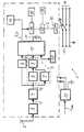
- FIG. 1shows schematically in the form of a block diagram a predictive protection device for an electrical consumer.
- the protective device 1 shown schematically in the figurecomprises a receiver with a magnetic loop antenna or Ferrritkemantenne 2 and an amplifier 3, which an analog filter 4 is connected downstream.
- the antenna 2serves as a measuring probe for recording the electrical activity due to an increase of the natural momentum radiation of the atmosphere in the long wave range.
- the antenna 2is fastened to a building wall or the like, for example, by means of an approximately 5 m long cable.
- the measurement signal M generated by the amplifier 3is decomposed in the filter 4 into the spectral components which are characteristic for lightning events. This type of prefiltering reduces the effects of noise and in some cases also technical interference.
- the filtered measurement signal M fis fed to a logic unit or a logic detector 5.
- the logic unit 5comprises an amplitude detector 6 for determining the maximum amplitude of the measurement signal M f and a counter 7 and a control logic module 8 connected to the latter and to the amplitude detector 6 on the input side.
- the logic unit 5serves to detect a received spherics signal on the basis of the amplitude and the time profile the measurement signal M f and makes a distinction or separation of this Spherics signal of technical interference.
- Parallel to the logic unit 5is an A / D converter 9, for example, an 8-bit ADC, which converts the maximum amplitude of the measurement signal M f, in particular for the purpose of subsequent analysis in a digital data format.
- the digital signal analysisis carried out with the help of a suitable, for example, stored in an EPROM software.
- the signal analysis or evaluationcan also take place by means of fuzzy logic, so that a corresponding algorithm is provided in an evaluation device in the form of a signal processor 10.
- Thisis generated by the logic unit 5 in the detection of a pulse radiation Control signal S L for reading the peak amplitude of the measuring signal M f supplied.
- the clocked by a quartz crystal 11 signal processor 10calculates from the amplitude-weighted frequency of the incoming pulses the risk of lightning strikes on the basis of the received and selected Spherics signal.
- the signal processor 10provides a digital risk value R, which simultaneously serves as a control signal S for a switching relay 12.
- the risk value Ris fed to an LCD display 13 and displayed there alphanumerically.
- the risk value Ris also supplied to a threshold value switch 14, which is connected to an adjustment regulator 15, for example in the form of a potentiometer. Thereby, the threshold for the separation of a connected to a 220V power supply 16 (not shown) electrical device or consumer can be set. If the risk value R exceeds the set threshold value, the switching relay 12 is activated via a driver module 17, which is connected to an LED display 18. The switching relay 12 takes over a coupled thereto switch 19 a two-pole separation of the load from the supply network 16 before.
- the signal processor 10is connected to a watchdog circuit 20 for permanent monitoring of the protection device 1. Further, a stabilized power supply 21 is provided to supply the protective device 1, the output side of a supplied mains voltage U net supplies a ⁇ 8V operating voltage.
- the protection device 1is advantageously integrated in a manner not shown in a housing in the form of a multiple socket or a timer, so that the protection device 1 can be switched between a power outlet and the electrical load.
- the protective device 1is suitably suitable for switching mains voltages up to 230V and switching currents of up to 10A.
- the housing dimensionsare expediently 100mm x 100mm x 30mm.
- the power consumptionis less than 50mW at rest and less than 180mW when measured. In the switching state, the power consumption is less than 2W.
- the weight of the entire protection device 1is less than 500g.
- the protection device 1By means of the protection device 1 is thus carried out an assessment of the risk of storm surges in the supply network 16 or on the corresponding supply lines by measuring and evaluating the locally present natural momentum radiation of the atmosphere. For this purpose, a detection and analysis of a detected or received Spherics signal.
- An increasingly occurring pulsed radiationmeans a high risk of lightning events and thus a high risk of overvoltages.
- the risk thresholdat which a disconnection from the supply network 16 takes place, can be switched on by means of the threshold switch 14, 15. Accordingly, the user can set the threshold such that on the one hand even with the slightest risk of possible overvoltage a shutdown already takes place, while also the possibility to choose a threshold in which switched off in always switched state of the electrical load even at a high risk situation becomes.
- a processor-controlled evaluation of the measurement signal M fwhich operates by means of fuzzy logic, and thus the risk of thunder-induced overvoltages can also take place. As a result, a reliable protection of the electrical load is achieved before a coupling of unacceptably high surges.
Landscapes
- Environmental & Geological Engineering (AREA)
- Engineering & Computer Science (AREA)
- Life Sciences & Earth Sciences (AREA)
- Atmospheric Sciences (AREA)
- Biodiversity & Conservation Biology (AREA)
- Ecology (AREA)
- Environmental Sciences (AREA)
- Emergency Protection Circuit Devices (AREA)
- Aiming, Guidance, Guns With A Light Source, Armor, Camouflage, And Targets (AREA)
Abstract
Description
Translated fromGermanDie Erfindung bezieht sich auf eine Vorrichtung zum Schutz eines elektrischen Verbrauchers gegen gewittterbedingte Überspannungen im Versorgungsnetz gemäß dem Oberbegriff des Anspruchs 1. Eine derartige Vorrichtung ist z.B. aus der
Ein derartiger Schutz gegen gewitterbedingte Überspannungen, ein sogenannter Blitzschutz, dient als Maßnahme zur Vermeidung von Schäden an Verbrauchern oder Endgeräten, die an ein Versorgungsnetz angeschlossen sind. Derartige Verbraucher sind üblicherweise elektrische oder elektronische Endgeräte, die an eine 110V- oder 220V-Versorgungsspannung angeschlossen werden.Such a protection against thunderstorm surges, a so-called lightning protection, serves as a measure to prevent damage to consumers or terminals that are connected to a supply network. Such consumers are usually electrical or electronic terminals which are connected to a 110V or 220V supply voltage.
Während bisherige Schutzmaßnahmen darauf ab zielen erst, infolge eines Blitzschlages auftretende Überspannungen vom Verbraucher oder Endgerät dadurch fernzuhalten, dass eine galvanische Trennung oder gezielte Ableitungen der durch atmosphärische Ent- und Aufladungen bedingten Überströme und Überspannung gegen Erde erfolgt, ist aus der
Der Erfindung liegt daher die Aufgabe zugrunde, eine Schutzvorrichtung anzugeben, die einen besonders zuverlässigen Schutz eines elektrischen Verbrauchers gegen gewitterbedingte Überspannungen gewährleistet.The invention is therefore based on the object to provide a protective device which ensures a particularly reliable protection of an electrical consumer against thunderstorms overvoltages.
Diese Aufgabe wird erfindungsgemäß gelöst durch die Merkmale des Anspruchs 1. Dazu wertet eine mit einem Empfänger verbundene Auswerteeinrichtung das empfangene Spherics-Signal hinsichtlich der daraus abgeleiteten Impulshäufigkeit aus und generiert bei erhöhtem Risiko von gewitterbedingten Überspannungen ein Steuersignal zur Abschaltung des Verbrauchers vom Versorgungsnetz.This object is achieved according to the invention by the features of claim 1. For this purpose, an evaluation device connected to a receiver evaluates the received Spherics signal with regard to the pulse frequency derived therefrom and generates a control signal for disconnecting the consumer from the supply network with an increased risk of thunderstorm surges.
Dabei erfolgt nicht erst im Falle von Überspannungen infoige von Blitzeinschlägen eine Trennung des Verbrauchers vom Versorgungsnetz, sondern es erfolgt nach Art eines prädikativen Blitzschutzes oder auseilenden Schutzes gegen Überspannungen eine Trennung vom Versorgungsnetz bereits beim Auftreten zu erwartender Überspannungen.It is not only in the case of overvoltages infoige of lightning strikes a separation of the consumer from the supply network, but it takes the manner of a predicative lightning protection or auseilenden protection against overvoltage separation from the supply already at the occurrence of expected overvoltages.
Der Erfindung liegt daher die Erkenntnis zugrunde, dass derartige Spherics-Signale elektromagnetische Signale in Form von unregelmäßig geformten Strahlungsimpulsen, sind die von dynamischen Prozessen in der Atmosphäre, beispielsweise im Vorfeld von Gewitter- oder Wetterfronten oder in konvektiven Bewölkungsformen, auftreten. Dabei sind einzeine Parameter der Spherics-Signale, wie z.B. die Anzahl, die Amplitude, die Frequenz der Schwingungen, die lmpulsfolgefrequenz, die Häufigkeitsverteilung auf die Frequenzwerte und die Signalformen, eng mit den sie auslösenden Wettervorgängen, insbesondere mit der Art und Bewegung von atmosphärischen Luftmassen, verknüpft. Durch Auswerten des empfangenen Spherics-Signals hinsichtlich der Impulshäufigkeit sind daher bereits frühzeitig gewitterbedingte Überspannungen besonders zuverlässig vorhersehbar.The invention is therefore based on the finding that such Spherics signals are electromagnetic signals in the form of irregularly shaped radiation pulses which occur from dynamic processes in the atmosphere, for example in the run-up to thunderstorm or weather fronts or in convective clouding forms. Here are some parameters of the Spherics signals, e.g. the number, the amplitude, the frequency of the oscillations, the pulse repetition frequency, the frequency distribution on the frequency values and the waveforms, closely linked to the weather events triggering them, in particular with the nature and movement of atmospheric air masses. By evaluating the received Spherics signal with regard to the pulse frequency, therefore, storm-induced overvoltages can be predicted with particular reliability at an early stage.
Diese Spherics-Signale haben eine lmpulsdauer bis zu einigen 100µs und bestehen aus einer oder mehreren Schwingungen, deren Schwingungsfrequenz im Niederfrequenzbereich bis etwa 100kHz und damit im Langwellenbereich liegen. Die maximale Amplitude der Spherics-Signale hängt von der Art und der Entfernung der Signalquelle ab und beträgt für den elektrischen Feldvektor bis zu einigen Volt pro Meter. Die typischen Entladungssiromstärken sind kleiner als 1kA, so dass die effektive Reichweite auf etwa 50km begrenzt ist.These Spherics signals have a pulse duration of up to several 100 μs and consist of one or more oscillations whose oscillation frequency lies in the low-frequency range up to about 100 kHz and thus in the long-wave range. The maximum amplitude of the Spherics signals depends on the type and distance of the signal source and is up to several volts per meter for the electric field vector. The typical discharge siren levels are less than 1kA, so the effective range is limited to about 50km.
In vorteilhafter Ausgestaltung enthält daher der Empfänger der Schutzvorrichtung eine magnetische Antenne, beispielsweise eine magnetische Rahmen- oder Ferritkernantenne, zum Empfangen von Langwellen, deren Quelle im Nahbereich liegt. Dadurch kann die im Bereich eines Gewittergebietes liegende Schutzvorrichtung das im Vorfeld eines Gewitters erzeugte Spherics-Signal empfangen. Die magnetische Rahmenantenne dient als Meßsonde zur Registrierung der elektrischen Aktivität infolge eines erheblichen Anstiegs der natürlichen lmpulsstrahlung der Atmosphäre aufgrund sich aufbauender Gewitterzellen oder Gewitterfronten. Diese Größe wird zur Prognose von Gewittern und somit zur Bewertung des Überspannungsrisikos verwendet. Dabei bedeutet eine verstärkt auftretende lmpulsstrahlung ein hohes Risiko von Blitzereignissen und somit ein hohes Risiko von Überspannungen.In an advantageous embodiment, therefore, the receiver of the protective device includes a magnetic antenna, such as a magnetic frame or ferrite core antenna, for receiving long waves whose source is in the vicinity. As a result, the protection device lying in the region of a thunderstorm area can receive the Spherics signal generated in the run-up to a thunderstorm. The magnetic loop antenna serves as a measuring probe for recording the electrical activity due to a considerable Increase of the natural pulsed radiation of the atmosphere due to build up of thunderstorm cells or storm fronts. This size is used to forecast thunderstorms and thus to assess overvoltage risk. An intensified pulsed radiation means a high risk of lightning events and thus a high risk of overvoltages.
Zur Generierung eines detektierbaren und analysierbaren Meßsignals ist zweckmäßigerweise der Antenne ein rauscharmer Verstärker, beispielsweise ein Operationsverstärker, nachgeschaltet. Dieser transformiert die von der Antenne gemessenen elektromagnetischen Impulse auf einen Spannungsbereich von vorzugsweise 1V bis 2V. Anschließend wird zweckmäßigerweise das gebildete Meßsignal mittels eines dem Verstärker nachgeschalteten analogen Filterbausteins in die für Blitzereignisse charakteristischen spektralen Anteile zerlegt. Durch diese Art der Vorfilterung werden Rauscheinflüsse und zumindest teilweise auch technische Störeinflüsse reduziert. Zur besonders zuverlässigen Selektierung des empfangenen Spherics-Signals von technischen Störungen ist zweckmäßigerweise eine Detektor-Logik-Einheit vorgesehen, die anhand der Amplitude und des Zeitverlaufes das Spherics-Signal erkennt und eine Unterscheidung von technischen Störungen vornimmt.To generate a detectable and analyzable measuring signal, the antenna is expediently connected downstream of a low-noise amplifier, for example an operational amplifier. This transforms the electromagnetic pulses measured by the antenna to a voltage range of preferably 1V to 2V. Subsequently, the measurement signal formed is expediently decomposed by means of an analog filter module connected downstream of the amplifier into the spectral components which are characteristic of lightning events. This type of prefiltering reduces the effects of noise and at least partially also technical interference. For particularly reliable selection of the received Spherics signal of technical interference, a detector-logic unit is expediently provided, which recognizes the Spherics signal on the basis of the amplitude and the time course and makes a distinction from technical disturbances.
Die Analyse des Spherics-Signals erfolgt in vorteilhafter Weiterbildung prozessorgesteuert mittels eines Signalprozessors, vorzugsweise eines 8 BIT-Microcontrollers. Diesem ist eingangsseitig ein Analog-/Digital-Wandler (A/D-Wandler) vorgeschaltet, der insbesondere im Hinblick auf eine spätere Analyse die Maximalamplitude des Signals bestimmt und in ein digitales Datenformat, vorzugsweise in ein 8 BIT-Datenwort, umwandelt.The analysis of the spherics signal is carried out in an advantageous development processor-controlled by means of a signal processor, preferably an 8-bit microcontroller. This is preceded by an analog / digital converter (A / D converter) on the input side, which determines the maximum amplitude of the signal, in particular with a view to subsequent analysis, and converts it into a digital data format, preferably an 8-bit data word.
Die Logikeinheit oder Detektorlogik generiert bei der Detektion einer Impulsstrahlung ein Steuersignal für den Signalprozessor zum Einlesen der Maximal- oder Spitzenamplitude. Aus der mit der Impulsamplitude gewichteten Häufigkeit der ankommenden Impulse berechnet der Signalprozessor das Risiko von Blitzeinschlägen und somit von unzulässig hohen gewitterbedingten Überspannungen. Anhand dieser Daten generiert der Signalprozessor ein digitales Steuersignal oder einen Risikowert, der mit einem LCD-Display angezeigt werden kann.The logic unit or detector logic generated upon detection of a pulse radiation, a control signal for the signal processor for reading the maximum or peak amplitude. From the pulse amplitude-weighted frequency of the incoming pulses, the signal processor calculates the risk of lightning strikes and thus of excessively high storm-induced overvoltages. Based on this data generated the signal processor a digital control signal or a risk value that can be displayed with an LCD display.
Das von der Auswerteeinrichtung generierte digitale Steuersignal wird zweckmäßigerweise einem Schwellwertschalter zugeführt, mit dem die Schwelle zur Trennung eines angeschlossenen Gerätes oder Verbrauchers eingestellt und damit festgelegt werden kann. Übersteigt der Wert des Steuersignals den eingestellten Schwellwert, so wird zweckmäßigerweise über einen Treiberbaustein ein Schaltrelais angesteuert, das die Netztrennung und damit die Abschaltung des Verbrauchers vom Versorgungsnetz vornimmt.The digital control signal generated by the evaluation device is expediently fed to a threshold value switch with which the threshold for disconnecting a connected device or consumer can be set and thus defined. If the value of the control signal exceeds the set threshold value, it is expedient to activate a switching relay via a driver module, which carries out the grid disconnection and thus the disconnection of the consumer from the supply network.
Die Schutzvorrichtung, deren Signalprozessor zweckmäßigerweise mittels eines Quarzes getaktet wird, ist vorteilhafterweise zusätzlich mit einer Watchdog-Schaltung versehen, die eine permanente Überwachung der Vorrichtung vornimmt. Findet beispielsweise ein überspannungsbedingter Systemausfall statt, so wird die Schutzvorrichtung innerhalb weniger Millisekunden erneut gestartet.The protection device whose signal processor is expediently clocked by means of a quartz is advantageously additionally provided with a watchdog circuit which carries out a permanent monitoring of the device. If, for example, a system failure due to overvoltage occurs, then the protection device is restarted within a few milliseconds.
Die mit der Erfindung erzielten Vorteile bestehen insbesondere darin, dass durch eine Schutzvorrichtung mit einer einem Empfänger nachgeschalteten Auswerteeinrichtung für ein empfangenes Spherics-Signal ein zuverlässiger Schutz eines elektrischen Verbrauchers gegen gewitterbedingte Überspannungen im Versorgungsnetz gewährleistet ist. Der Schutz wirkt dabei prädiktiv oder vorauseilend, so dass eine Trennung des elektrischen Verbrauchers vom Versorgungsnetz bereits erfolgt ist, wenn mit hoher Wahrscheinlichkeit erwartete gewitterbedingte Überspannungen infolge eines Blitzeinschlags auftreten. Eine automatische galvanische Trennung des elektrischen Verbrauchers von der Versorgungs- oder Netzspannung erfolgt dabei vorteilhafterweise möglichst kurzzeitig vor Auftreten einer möglichen Überspannung, d.h. bei einem erhöhten Risiko von Überspannungen infolge von Blitzeinschlägen. Dadurch wird einerseits ein Geräteschaden, der bisher infolge des zu trägen Abschaltvorganges auftrat, sicher vermieden. Andererseits wird die bestimmungsgemäße Nutzung des elektrischen Verbrauchers nicht unnötig eingeschränkt.The advantages achieved by the invention are, in particular, that a reliable protection of an electrical consumer against thunderstorm surges in the supply network is ensured by a protective device with a receiver downstream of an evaluation device for a received Spherics signal. The protection acts predictive or anticipatory, so that a separation of the electrical load from the supply network has already taken place when with high probability expected thunderstorm surges occur as a result of lightning. An automatic electrical isolation of the electrical load from the supply or mains voltage advantageously takes place as briefly as possible before the occurrence of a possible overvoltage, ie at an increased risk of overvoltages as a result of lightning strikes. As a result, on the one hand device damage that previously occurred as a result of too slow shutdown, safely avoided. On the other hand, the intended use of the electrical load is not unnecessarily limited.
Nachfolgend wird ein Ausführungsbeispiel der Erfindung anhand einer Zeichnung näher erläutert. Darin zeigt die Figur schematisch in Form eines Blockschaltbilds eine prädiktive Schutzvorrichtung für einen elektrischen Verbraucher.An embodiment of the invention will be explained in more detail with reference to a drawing. Therein, the figure shows schematically in the form of a block diagram a predictive protection device for an electrical consumer.
Die in der Figur schematisch dargestellte Schutzvorrichtung 1 umfasst einen Empfänger mit einer magnetischen Rahmenantenne oder Ferritkemantenne 2 und einen Verstärker 3, dem ein analoger Filter 4 nachgeschaltet ist. Die Antenne 2 dient als Meßsonde zur Registrierung der elektrischen Aktivität infolge eines Anstiegs der natürlichen Impulsstrahlung der Atmosphäre im Langwellen-Bereich. Die Antenne 2 wird beispielsweise mittels eines etwa 5m langen Kabels an einer Gebäudewand oder dergleichen befestigt. Der nachgeschaltete Verstärker 3, beispielsweise ein Operationsverstärker, transformiert das empfangene Signal auf einen Spannungsbereich von vorzugsweise 1 V bis 2V. Das vom Verstärker 3 generierte Meßsignal M wird im Filter 4 in die für Blitzereignisse charakteristischen spektralen Anteile zerlegt. Durch diese Art der Vorfilterung werden Rauscheinflüsse und teilweise auch technische Störeinflüsse reduziert.The protective device 1 shown schematically in the figure comprises a receiver with a magnetic loop antenna or Ferrritkemantenne 2 and an
Das gefilterte Meßsignal Mf wird einer Logikeinheit oder einem Logikdetektor 5 zugeführt. Die Logikeinheit 5 umfasst einen Amplitudendetektor 6 zur Bestimmung der Maximalamplitude des Meßsignals Mf und einen Zähler 7 sowie eine mit diesem und mit dem Amplitudendetektor 6 eingangsseitig verbundenen Steuerlogikbaustein 8. Die Logikeinheit 5 dient zur Erkennung eines empfangenen Spherics-Signals anhand der Amplitude und des Zeitverlaufes des Meßsignals Mf und nimmt eine Unterscheidung oder Trennung dieses Spherics-Signals von technischen Störungen vor. Parallel zur Logikeinheit 5 liegt ein A/D-Wandler 9, beispielsweise ein 8 Bit ADU, der die Maximalamplitude des Meßsignals Mf insbesondere zum Zwecke einer späteren Analyse in ein digitales Datenformat umwandelt.The filtered measurement signal Mf is fed to a logic unit or a logic detector 5. The logic unit 5 comprises an
Die digitale Signalanalyse wird mit Hilfe einer geeigneten, beispielsweise in einem EPROM abgelegten Software vorgenommen. Dabei kann die Signalanalyse oder Auswertung auch mittels Fuzzy-Logik erfolgen, so dass ein entsprechender Algorithmus in einer Auswerteeinrichtung in Form eines Signalprozessors 10 vorgesehen ist. Diesem wird ein von der Logikeinheit 5 bei der Detektion einer Impulsstrahlung generiertes Steuersignal SL zum Einlesen der Spitzenamplitude des Meßsignals Mf zugeführt. Der mittels eines Quarzes 11 getaktete Signalprozessor 10 berechnet aus der mit der Amplitude gewichteten Häufigkeit der ankommenden Impulse das Risiko von Blitzeinschlägen anhand des empfangenen und selektierten Spherics-Signals. Im Ergebnis liefert der Signalprozessor 10 einen digitalen Risikowert R, der gleichzeitig als Steuersignal S für ein Schaltrelais 12 dient. Der Risikowert R wird einem LCD-Display 13 zugeführt und dort alphanumerisch dargestellt.The digital signal analysis is carried out with the help of a suitable, for example, stored in an EPROM software. In this case, the signal analysis or evaluation can also take place by means of fuzzy logic, so that a corresponding algorithm is provided in an evaluation device in the form of a
Der Risikowert R wird außerdem einem Schwellwertschalter 14 zugeführt, der mit einem Einstellregler 15, beispielsweise in Form eines Potentiometers, verbunden ist. Dadurch kann die Schwelle zur Trennung eines an ein 220V-Versorgungsnetz 16 angeschlossenen (nicht dargestellten) elektrischen Gerätes oder Verbrauchers festgelegt werden. Übersteigt der Risikowert R den eingestellten Schwellwert, so wird über einen Treiberbaustein 17, der mit einer LED-Anzeige 18 verbunden ist, das Schaltrelais 12 angesteuert. Das Schaltrelais 12 nimmt über einen mit diesem gekoppelten Schalter 19 eine zweipolige Trennung des Verbrauchers vom Versorgungsnetz 16 vor.The risk value R is also supplied to a
Der Signalprozessor 10 ist mit einer Watchdog-Schaltung 20 zur permanenten Überwachung der Schutzvorrichtung 1 verbunden. Ferner ist zur Versorgung der Schutzvorrichtung 1 ein stabilisiertes Netzteil 21 vorgesehen, das aus einer zugeführten Netzspannung Unetz ausgangsseitig eine ±8V-Betriebsspannung liefert. Die Schutzvorrichtung 1 ist in nicht näher dargestellter Art und Weise vorteilhafterweise in ein Gehäuse in Form einer Mehrfachsteckdose oder einer Zeitschaltuhr integriert, so dass die Schutzvorrichtung 1 zwischen eine Netzsteckdose und den elektrischen Verbraucher geschaltet werden kann.The
Die Schutzvorrichtung 1 eignet sich zweckmäßigerweise zur Schaltung von Netzspannungen bis 230V und Schaltströmen von bis 10A. Die Gehäuseabmessungen betragen zweckmäßigerweise 100mm x 100mm x 30mm. Die Leistungsaufnahme beträgt im Ruhezustand weniger als 50mW und im Meßzustand weniger als 180mW. Im Schaltzustand beträgt die Leistungsaufnahme weniger als 2W. Das Gewicht der gesamten Schutzvorrichtung 1 beträgt weniger als 500g.The protective device 1 is suitably suitable for switching mains voltages up to 230V and switching currents of up to 10A. The housing dimensions are expediently 100mm x 100mm x 30mm. The power consumption is less than 50mW at rest and less than 180mW when measured. In the switching state, the power consumption is less than 2W. The weight of the entire protection device 1 is less than 500g.
Mittels der Schutzvorrichtung 1 erfolgt somit eine Bewertung des Risikos von gewitterbedingten Überspannungen im Versorgungsnetz 16 oder auf den entsprechenden Versorgungsleitungen durch Messung und Auswertung der lokal vorhandenen natürlichen Impulsstrahlung der Atmosphäre. Dazu erfolgt eine Detektion und Analyse eines erfassten oder empfangenen Spherics-Signals. Eine verstärkt auftretende lmpulsstrahlung bedeutet dabei ein hohes Risiko von Blitzereignissen und somit ein hohes Risiko von Überspannungen.By means of the protection device 1 is thus carried out an assessment of the risk of storm surges in the
Da das Risikomaß zwischen 0% und 100% liegt, ist die Risikoschwelle, bei der eine Trennung vom Versorgungsnetz 16 erfolgt, mittels des Schwellwertschalters 14,15 entsprechend einschaltbar. Demnach kann der Benutzer die Schwelle derart festlegen, dass einerseits auch bei geringstem Risiko einer möglichen Überspannung bereits eine Abschaltung erfolgt, während ebenso die Möglichkeit besteht, eine Schwelle zu wählen, bei der in stets durchgeschaltetem Zustand der elektrische Verbraucher auch bei einer hohen Gefährdungslage nicht abgeschaltet wird.Since the risk measure is between 0% and 100%, the risk threshold, at which a disconnection from the
Durch Verwendung eines entsprechend programmierten Signalprozessors 10, vorzugsweise eines 8 Bit-Microcontrollers, kann auch eine mittels Fuzzy-Logik arbeitende prozessorgesteuerte Auswertung des Meßsignals Mf und damit des Risikos von gewitterbedingten Überspannungen erfolgen. Dadurch wird ein zuverlässiger Schutz des elektrischen Verbrauchers vor einer Einkopplung von unzulässig hohen Überspannungen erzielt.By using a suitably programmed
- 11
- Versorgungsschutz/BlitzschutzSupply Protection / Lightning Protection
- 22
- Antenneantenna
- 33
- Verstärker/OperationsverstärkerAmplifier / operational amplifier
- 44
- Filterfilter
- 55
- Logikeinheit/DetektoriogikLogic unit / Detektoriogik
- 66
- Amplitudendetektoramplitude detector
- 77
- Zählercounter
- 88th
- Steuerlogikcontrol logic
- 99
- A/D-WandlerA / D converter
- 1010
- Signalprozessor/AuswerteeinrichtungSignal processor / evaluation
- 1111
- Quarzquartz
- 1212
- Schaltrelaisswitching Relays
- 1313
- LCD-DisplayLCD display
- 1414
- Schwellwertschalterthreshold
- 1515
- Einstellregleradjusting controller
- 1616
- Versorgungsnetzsupply network
- 1717
- Treiberdriver
- 1818
- LED-AnzeigeLED display
- 1919
- Schalterswitch
- 2020
- Watchdog-SchaltungWatchdog circuit
- 2121
- Netzteilpower adapter
- M,MfM, Mf
- Meßsignalmeasuring signal
- RR
- Risikowertrisk value
- S,SLS, SL
- Steuersignalcontrol signal
- UnetzUnetwork
- Netzspannungmains voltage
Claims (10)
- Device for protecting an electrical consumer against surges in a supply network (16) caused by thunderstorms, comprising a receiver (2), a series-connected evaluating device for carrying out an analysis of a received spherics signal and a switching equipment (12,19) for disconnecting the consumer from said supply network (16) according to a control signal (S), generated by said evaluating device,characterized in that the evaluation of said received spherics signal (Mf) depends from the pulse rate deduced from said spherics signals.
- Device according to claim 1, wherein said receiver (2) includes a magnetic antenna and a series-connected signal processing unit (3, 4) comprising an analogue filter (4) for the spectral analysis of an received signal (M).
- Device according to claim 2, wherein said signal processing unit (3, 4) further comprises an amplifier (3) for the transformation of said received signal (M) to a defined voltage range, preferably from 1V to 2V.
- Device according to one of claims 1 to 3, wherein said evaluating device includes a digital signal processing unit (10) for carrying out an analysis of pulse rate and pulse amplitude derived from said received spherics signal (Mf).
- Device according to claim 4, wherein an Analogue-Digital-Converter (9) for generating a multi-bit data word representing the maximal amplitude and an logical unit (5) for generating a control signal (SL), deduced from the pulse rate in order to read in the maximal amplitude are series-connected to said signal processing unit (10).
- Device according to claim 5, wherein said logical unit (5) includes an amplitude detector (6) and a series-connected control unit (8), which is connected with a counter (7) at the input side.
- Device according to one of the claims 1 to 6, wherein said evaluating device is connected at the output side with a switching relay (12), coupled with a one-pole or multi-pole switch located at said supply network (16).
- Device according to claim 7, wherein said evaluating device is connected by an adjustable threshold value switch (14, 15), to said switching relay (12).
- Device according to one of the claims 1 to 7, wherein said evaluating device discharges an output signal (R, S), to a LCD display (13) displaying in digital form the risk value of an possible overvoltage.
- Device according to one of the claims 4 to 9, wherein further said signal processor (10) a quartz clock (11) for providing the clock frequency is assigned.
Applications Claiming Priority (3)
| Application Number | Priority Date | Filing Date | Title |
|---|---|---|---|
| DE19744129 | 1997-10-01 | ||
| DE19744129 | 1997-10-01 | ||
| PCT/EP1998/006252WO1999017413A1 (en) | 1997-10-01 | 1998-10-01 | Protective device, especially for protection against lightning |
Publications (2)
| Publication Number | Publication Date |
|---|---|
| EP1023755A1 EP1023755A1 (en) | 2000-08-02 |
| EP1023755B1true EP1023755B1 (en) | 2007-06-13 |
Family
ID=7844755
Family Applications (1)
| Application Number | Title | Priority Date | Filing Date |
|---|---|---|---|
| EP98949000AExpired - LifetimeEP1023755B1 (en) | 1997-10-01 | 1998-10-01 | Protective device, especially for protection against lightning |
Country Status (5)
| Country | Link |
|---|---|
| EP (1) | EP1023755B1 (en) |
| AT (1) | ATE364924T1 (en) |
| AU (1) | AU9542098A (en) |
| DE (2) | DE59814033D1 (en) |
| WO (1) | WO1999017413A1 (en) |
Families Citing this family (3)
| Publication number | Priority date | Publication date | Assignee | Title |
|---|---|---|---|---|
| US5959815A (en)* | 1998-03-17 | 1999-09-28 | Gateway 2000, Inc. | Method and apparatus for detecting potentially damaging electrical fields |
| CN112821339B (en)* | 2021-01-06 | 2022-12-06 | 南方电网科学研究院有限责任公司 | A retrofit method for lightning protection measures in operating distribution network |
| CN112803344B (en)* | 2021-01-06 | 2022-10-28 | 南方电网科学研究院有限责任公司 | Lightning protection configuration method for newly-built power distribution network |
Family Cites Families (3)
| Publication number | Priority date | Publication date | Assignee | Title |
|---|---|---|---|---|
| US4276576A (en)* | 1978-12-27 | 1981-06-30 | Lightning Location And Protection, Inc. | Lightning activated relay |
| US5291208A (en)* | 1992-04-30 | 1994-03-01 | Rabun Labs, Inc. | Incipient lightning detection and device protection |
| US5537318A (en)* | 1994-07-13 | 1996-07-16 | B. F. Goodrich Flightsystems, Inc. | Lightning strike detection and mapping system |
- 1998
- 1998-10-01AUAU95420/98Apatent/AU9542098A/ennot_activeAbandoned
- 1998-10-01WOPCT/EP1998/006252patent/WO1999017413A1/enactiveIP Right Grant
- 1998-10-01EPEP98949000Apatent/EP1023755B1/ennot_activeExpired - Lifetime
- 1998-10-01DEDE59814033Tpatent/DE59814033D1/ennot_activeExpired - Lifetime
- 1998-10-01DEDE19881426Tpatent/DE19881426D2/ennot_activeExpired - Fee Related
- 1998-10-01ATAT98949000Tpatent/ATE364924T1/enactive
Also Published As
| Publication number | Publication date |
|---|---|
| ATE364924T1 (en) | 2007-07-15 |
| EP1023755A1 (en) | 2000-08-02 |
| AU9542098A (en) | 1999-04-23 |
| DE59814033D1 (en) | 2007-07-26 |
| DE19881426D2 (en) | 2001-02-22 |
| WO1999017413A1 (en) | 1999-04-08 |
Similar Documents
| Publication | Publication Date | Title |
|---|---|---|
| US6459997B1 (en) | Method for event analysis at an intelligent electronic device | |
| DE10029235B4 (en) | Method for detecting systematic error conditions in a smart electronic device | |
| US5512832A (en) | Energy analysis fault detection system | |
| US5602709A (en) | High impedance fault detector | |
| US5578931A (en) | ARC spectral analysis system | |
| US5977762A (en) | Lightning detection apparatus and methodology | |
| US20190079132A1 (en) | Method and Apparatus for Arc Fault Detection in Electrical Systems | |
| US5168212A (en) | Autonomous electro-optical lightning identification and ranging apparatus for, and method of, alerting humans and protecting equipment | |
| CN109035839B (en) | Comprehensive monitoring method for electrical safety of traffic signal device | |
| US11231999B2 (en) | Detection of electric power system anomalies in streaming measurements | |
| GB2375244A (en) | Arc fault detection system | |
| US10958060B2 (en) | Method and device for detecting an electric arc in a photovoltaic installation | |
| EP3024103B1 (en) | Testing method and apparatus for a lightning arrester | |
| WO1999056140A1 (en) | Method and device for monitoring an electrode line of a bipolar high voltage direct current (hvdc) transmission system | |
| EP0823057B1 (en) | Process for monitoring a three-phase mains for a change in the tuning of the arc supression coil | |
| Huecker et al. | UHF partial discharge monitoring and expert system diagnosis | |
| EP1023755B1 (en) | Protective device, especially for protection against lightning | |
| EP3655786B1 (en) | Method and arrangement for detecting partial discharges in an electric operating means | |
| CN112834808B (en) | Lightning invasion wave monitoring method and system | |
| CN210243745U (en) | Intelligent ground resistance monitoring terminal of highway lightning grounding device | |
| DE102018111308B3 (en) | Apparatus for detecting electrical currents at or near electrical conductors | |
| CN211480924U (en) | Lightning protection integrated management device | |
| DE19640821B4 (en) | Method and device for detecting earth faults | |
| US12055576B2 (en) | Calculating electric power noise distributions | |
| CN208819332U (en) | A kind of network edition fence detection system |
Legal Events
| Date | Code | Title | Description |
|---|---|---|---|
| PUAI | Public reference made under article 153(3) epc to a published international application that has entered the european phase | Free format text:ORIGINAL CODE: 0009012 | |
| 17P | Request for examination filed | Effective date:20000428 | |
| AK | Designated contracting states | Kind code of ref document:A1 Designated state(s):AT BE CH CY DE DK ES FI FR GB GR IE IT LI LU MC NL PT SE | |
| GRAP | Despatch of communication of intention to grant a patent | Free format text:ORIGINAL CODE: EPIDOSNIGR1 | |
| GRAJ | Information related to disapproval of communication of intention to grant by the applicant or resumption of examination proceedings by the epo deleted | Free format text:ORIGINAL CODE: EPIDOSDIGR1 | |
| GRAP | Despatch of communication of intention to grant a patent | Free format text:ORIGINAL CODE: EPIDOSNIGR1 | |
| GRAS | Grant fee paid | Free format text:ORIGINAL CODE: EPIDOSNIGR3 | |
| GRAA | (expected) grant | Free format text:ORIGINAL CODE: 0009210 | |
| AK | Designated contracting states | Kind code of ref document:B1 Designated state(s):AT BE CH CY DE DK ES FI FR GB GR IE IT LI LU MC NL PT SE | |
| REG | Reference to a national code | Ref country code:GB Ref legal event code:FG4D Free format text:NOT ENGLISH | |
| REG | Reference to a national code | Ref country code:CH Ref legal event code:EP | |
| REG | Reference to a national code | Ref country code:IE Ref legal event code:FG4D Free format text:LANGUAGE OF EP DOCUMENT: GERMAN | |
| REF | Corresponds to: | Ref document number:59814033 Country of ref document:DE Date of ref document:20070726 Kind code of ref document:P | |
| PG25 | Lapsed in a contracting state [announced via postgrant information from national office to epo] | Ref country code:SE Free format text:LAPSE BECAUSE OF FAILURE TO SUBMIT A TRANSLATION OF THE DESCRIPTION OR TO PAY THE FEE WITHIN THE PRESCRIBED TIME-LIMIT Effective date:20070913 | |
| NLV1 | Nl: lapsed or annulled due to failure to fulfill the requirements of art. 29p and 29m of the patents act | ||
| GBV | Gb: ep patent (uk) treated as always having been void in accordance with gb section 77(7)/1977 [no translation filed] | Effective date:20070613 | |
| REG | Reference to a national code | Ref country code:IE Ref legal event code:FD4D | |
| PG25 | Lapsed in a contracting state [announced via postgrant information from national office to epo] | Ref country code:PT Free format text:LAPSE BECAUSE OF FAILURE TO SUBMIT A TRANSLATION OF THE DESCRIPTION OR TO PAY THE FEE WITHIN THE PRESCRIBED TIME-LIMIT Effective date:20071113 Ref country code:NL Free format text:LAPSE BECAUSE OF FAILURE TO SUBMIT A TRANSLATION OF THE DESCRIPTION OR TO PAY THE FEE WITHIN THE PRESCRIBED TIME-LIMIT Effective date:20070613 Ref country code:IE Free format text:LAPSE BECAUSE OF FAILURE TO SUBMIT A TRANSLATION OF THE DESCRIPTION OR TO PAY THE FEE WITHIN THE PRESCRIBED TIME-LIMIT Effective date:20070613 Ref country code:ES Free format text:LAPSE BECAUSE OF FAILURE TO SUBMIT A TRANSLATION OF THE DESCRIPTION OR TO PAY THE FEE WITHIN THE PRESCRIBED TIME-LIMIT Effective date:20070924 | |
| EN | Fr: translation not filed | ||
| PLBE | No opposition filed within time limit | Free format text:ORIGINAL CODE: 0009261 | |
| STAA | Information on the status of an ep patent application or granted ep patent | Free format text:STATUS: NO OPPOSITION FILED WITHIN TIME LIMIT | |
| PG25 | Lapsed in a contracting state [announced via postgrant information from national office to epo] | Ref country code:IT Free format text:LAPSE BECAUSE OF FAILURE TO SUBMIT A TRANSLATION OF THE DESCRIPTION OR TO PAY THE FEE WITHIN THE PRESCRIBED TIME-LIMIT Effective date:20070613 Ref country code:GR Free format text:LAPSE BECAUSE OF FAILURE TO SUBMIT A TRANSLATION OF THE DESCRIPTION OR TO PAY THE FEE WITHIN THE PRESCRIBED TIME-LIMIT Effective date:20070914 Ref country code:GB Free format text:LAPSE BECAUSE OF FAILURE TO SUBMIT A TRANSLATION OF THE DESCRIPTION OR TO PAY THE FEE WITHIN THE PRESCRIBED TIME-LIMIT Effective date:20070613 Ref country code:DK Free format text:LAPSE BECAUSE OF FAILURE TO SUBMIT A TRANSLATION OF THE DESCRIPTION OR TO PAY THE FEE WITHIN THE PRESCRIBED TIME-LIMIT Effective date:20070613 | |
| 26N | No opposition filed | Effective date:20080314 | |
| PG25 | Lapsed in a contracting state [announced via postgrant information from national office to epo] | Ref country code:MC Free format text:LAPSE BECAUSE OF NON-PAYMENT OF DUE FEES Effective date:20071031 | |
| PG25 | Lapsed in a contracting state [announced via postgrant information from national office to epo] | Ref country code:FR Free format text:LAPSE BECAUSE OF FAILURE TO SUBMIT A TRANSLATION OF THE DESCRIPTION OR TO PAY THE FEE WITHIN THE PRESCRIBED TIME-LIMIT Effective date:20080208 | |
| ET | Fr: translation filed | ||
| REG | Reference to a national code | Ref country code:FR Ref legal event code:EERR Free format text:CORRECTION DE BOPI 08/06 - BREVETS EUROPEENS DONT LA TRADUCTION N A PAS ETE REMISE A L INPI. IL Y A LIEU DE SUPPRIMER : LA MENTION DE LA NON-REMISE. LA REMISE DE LA TRADUCTION EST PUBLIEE DANS LE PRESENT BOPI. | |
| PG25 | Lapsed in a contracting state [announced via postgrant information from national office to epo] | Ref country code:FI Free format text:LAPSE BECAUSE OF FAILURE TO SUBMIT A TRANSLATION OF THE DESCRIPTION OR TO PAY THE FEE WITHIN THE PRESCRIBED TIME-LIMIT Effective date:20070613 | |
| REG | Reference to a national code | Ref country code:CH Ref legal event code:PL | |
| PG25 | Lapsed in a contracting state [announced via postgrant information from national office to epo] | Ref country code:CY Free format text:LAPSE BECAUSE OF FAILURE TO SUBMIT A TRANSLATION OF THE DESCRIPTION OR TO PAY THE FEE WITHIN THE PRESCRIBED TIME-LIMIT Effective date:20070613 | |
| REG | Reference to a national code | Ref country code:CH Ref legal event code:AEN Free format text:DAS PATENT IST AUFGRUND DES WEITERBEHANDLUNGSANTRAGS VOM 15.07.2009 REAKTIVIERT WORDEN. | |
| PG25 | Lapsed in a contracting state [announced via postgrant information from national office to epo] | Ref country code:LU Free format text:LAPSE BECAUSE OF NON-PAYMENT OF DUE FEES Effective date:20071001 | |
| PG25 | Lapsed in a contracting state [announced via postgrant information from national office to epo] | Ref country code:LI Free format text:LAPSE BECAUSE OF NON-PAYMENT OF DUE FEES Effective date:20081031 Ref country code:CH Free format text:LAPSE BECAUSE OF NON-PAYMENT OF DUE FEES Effective date:20081031 | |
| REG | Reference to a national code | Ref country code:FR Ref legal event code:ST Effective date:20100630 | |
| PG25 | Lapsed in a contracting state [announced via postgrant information from national office to epo] | Ref country code:FR Free format text:LAPSE BECAUSE OF NON-PAYMENT OF DUE FEES Effective date:20091102 | |
| REG | Reference to a national code | Ref country code:FR Ref legal event code:RN | |
| REG | Reference to a national code | Ref country code:FR Ref legal event code:FC | |
| PGRI | Patent reinstated in contracting state [announced from national office to epo] | Ref country code:FR Effective date:20110126 | |
| REG | Reference to a national code | Ref country code:DE Ref legal event code:R081 Ref document number:59814033 Country of ref document:DE Owner name:ELWE TECHNIK GMBH, DE Free format text:FORMER OWNER: SPHERICS MESS- UND ANALYSETECHNIK GMBH, 96215 LICHTENFELS, DE Effective date:20110408 | |
| REG | Reference to a national code | Ref country code:CH Ref legal event code:PUE Owner name:ELWE TECHNIK GMBH Free format text:SPHERICS MESS- UND ANALYSETECHNIK GMBH#BAMBERGER STRASSE 10,#96215 LICHTENFELS (DE) -TRANSFER TO- ELWE TECHNIK GMBH#ELWESTRASSE 6#38162 CREMLINGEN (DE) | |
| REG | Reference to a national code | Ref country code:FR Ref legal event code:TP Owner name:ELWE TECHNIK GMBH, DE Effective date:20121030 | |
| REG | Reference to a national code | Ref country code:AT Ref legal event code:PC Ref document number:364924 Country of ref document:AT Kind code of ref document:T Owner name:HANNA PABST, DE Effective date:20130131 Ref country code:AT Ref legal event code:PC Ref document number:364924 Country of ref document:AT Kind code of ref document:T Owner name:HEINO MUELLER, DE Effective date:20130131 | |
| PGFP | Annual fee paid to national office [announced via postgrant information from national office to epo] | Ref country code:CH Payment date:20130913 Year of fee payment:16 | |
| PGFP | Annual fee paid to national office [announced via postgrant information from national office to epo] | Ref country code:AT Payment date:20141224 Year of fee payment:17 | |
| PGFP | Annual fee paid to national office [announced via postgrant information from national office to epo] | Ref country code:DE Payment date:20141224 Year of fee payment:17 | |
| PGFP | Annual fee paid to national office [announced via postgrant information from national office to epo] | Ref country code:FR Payment date:20141224 Year of fee payment:17 | |
| REG | Reference to a national code | Ref country code:CH Ref legal event code:PL | |
| PGFP | Annual fee paid to national office [announced via postgrant information from national office to epo] | Ref country code:BE Payment date:20141230 Year of fee payment:17 | |
| PG25 | Lapsed in a contracting state [announced via postgrant information from national office to epo] | Ref country code:CH Free format text:LAPSE BECAUSE OF NON-PAYMENT OF DUE FEES Effective date:20141031 Ref country code:LI Free format text:LAPSE BECAUSE OF NON-PAYMENT OF DUE FEES Effective date:20141031 | |
| REG | Reference to a national code | Ref country code:DE Ref legal event code:R119 Ref document number:59814033 Country of ref document:DE | |
| REG | Reference to a national code | Ref country code:AT Ref legal event code:MM01 Ref document number:364924 Country of ref document:AT Kind code of ref document:T Effective date:20151001 | |
| PG25 | Lapsed in a contracting state [announced via postgrant information from national office to epo] | Ref country code:DE Free format text:LAPSE BECAUSE OF NON-PAYMENT OF DUE FEES Effective date:20160503 | |
| REG | Reference to a national code | Ref country code:FR Ref legal event code:ST Effective date:20160630 | |
| PG25 | Lapsed in a contracting state [announced via postgrant information from national office to epo] | Ref country code:AT Free format text:LAPSE BECAUSE OF NON-PAYMENT OF DUE FEES Effective date:20151001 Ref country code:FR Free format text:LAPSE BECAUSE OF NON-PAYMENT OF DUE FEES Effective date:20151102 | |
| PG25 | Lapsed in a contracting state [announced via postgrant information from national office to epo] | Ref country code:BE Free format text:LAPSE BECAUSE OF NON-PAYMENT OF DUE FEES Effective date:20151031 |