EP1022565A2 - Method and device for withdrawing analytical consumables from a storage container - Google Patents
Method and device for withdrawing analytical consumables from a storage containerDownload PDFInfo
- Publication number
- EP1022565A2 EP1022565A2EP00100255AEP00100255AEP1022565A2EP 1022565 A2EP1022565 A2EP 1022565A2EP 00100255 AEP00100255 AEP 00100255AEP 00100255 AEP00100255 AEP 00100255AEP 1022565 A2EP1022565 A2EP 1022565A2
- Authority
- EP
- European Patent Office
- Prior art keywords
- plunger
- consumable
- feed
- transport
- control
- Prior art date
- Legal status (The legal status is an assumption and is not a legal conclusion. Google has not performed a legal analysis and makes no representation as to the accuracy of the status listed.)
- Granted
Links
- 238000000034methodMethods0.000titleclaimsabstractdescription10
- 238000012360testing methodMethods0.000claimsabstractdescription44
- 230000033001locomotionEffects0.000claimsabstractdescription27
- 238000004458analytical methodMethods0.000claimsabstractdescription12
- 238000003780insertionMethods0.000claimsdescription14
- 230000037431insertionEffects0.000claimsdescription14
- 238000000605extractionMethods0.000abstract2
- 230000000149penetrating effectEffects0.000abstract1
- 238000005265energy consumptionMethods0.000description9
- 230000001419dependent effectEffects0.000description7
- 239000000463materialSubstances0.000description6
- 230000008901benefitEffects0.000description5
- 239000011888foilSubstances0.000description5
- 238000005259measurementMethods0.000description5
- 238000013461designMethods0.000description4
- 238000010586diagramMethods0.000description4
- 230000035515penetrationEffects0.000description4
- 230000008569processEffects0.000description4
- 238000012549trainingMethods0.000description4
- 238000006073displacement reactionMethods0.000description3
- 238000007789sealingMethods0.000description3
- 229910000639Spring steelInorganic materials0.000description2
- 230000033228biological regulationEffects0.000description2
- 230000005540biological transmissionEffects0.000description2
- 230000008094contradictory effectEffects0.000description2
- 230000008878couplingEffects0.000description2
- 238000010168coupling processMethods0.000description2
- 238000005859coupling reactionMethods0.000description2
- 230000007423decreaseEffects0.000description2
- 230000000694effectsEffects0.000description2
- WQZGKKKJIJFFOK-GASJEMHNSA-NGlucoseNatural productsOC[C@H]1OC(O)[C@H](O)[C@@H](O)[C@@H]1OWQZGKKKJIJFFOK-GASJEMHNSA-N0.000description1
- 206010036790Productive coughDiseases0.000description1
- 244000052616bacterial pathogenSpecies0.000description1
- 238000005452bendingMethods0.000description1
- 238000012742biochemical analysisMethods0.000description1
- 230000015572biosynthetic processEffects0.000description1
- 239000008280bloodSubstances0.000description1
- 210000004369bloodAnatomy0.000description1
- 239000003153chemical reaction reagentSubstances0.000description1
- 230000000052comparative effectEffects0.000description1
- 230000006835compressionEffects0.000description1
- 238000007906compressionMethods0.000description1
- 238000010276constructionMethods0.000description1
- 230000003247decreasing effectEffects0.000description1
- 230000006735deficitEffects0.000description1
- 239000002274desiccantSubstances0.000description1
- 238000002405diagnostic procedureMethods0.000description1
- 239000000428dustSubstances0.000description1
- 238000005516engineering processMethods0.000description1
- 230000007613environmental effectEffects0.000description1
- 238000011156evaluationMethods0.000description1
- 239000008103glucoseSubstances0.000description1
- 230000003993interactionEffects0.000description1
- 239000007788liquidSubstances0.000description1
- 238000004519manufacturing processMethods0.000description1
- 230000009347mechanical transmissionEffects0.000description1
- 230000004048modificationEffects0.000description1
- 238000012986modificationMethods0.000description1
- 230000003287optical effectEffects0.000description1
- 230000009467reductionEffects0.000description1
- 230000004044responseEffects0.000description1
- 238000005070samplingMethods0.000description1
- 239000007787solidSubstances0.000description1
- 239000000126substanceSubstances0.000description1
- 238000005353urine analysisMethods0.000description1
- 238000004804windingMethods0.000description1
Images


Classifications
- B—PERFORMING OPERATIONS; TRANSPORTING
- B01—PHYSICAL OR CHEMICAL PROCESSES OR APPARATUS IN GENERAL
- B01L—CHEMICAL OR PHYSICAL LABORATORY APPARATUS FOR GENERAL USE
- B01L99/00—Subject matter not provided for in other groups of this subclass
- G—PHYSICS
- G01—MEASURING; TESTING
- G01N—INVESTIGATING OR ANALYSING MATERIALS BY DETERMINING THEIR CHEMICAL OR PHYSICAL PROPERTIES
- G01N33/00—Investigating or analysing materials by specific methods not covered by groups G01N1/00 - G01N31/00
- G01N33/48—Biological material, e.g. blood, urine; Haemocytometers
- G01N33/483—Physical analysis of biological material
- G01N33/487—Physical analysis of biological material of liquid biological material
- G01N33/4875—Details of handling test elements, e.g. dispensing or storage, not specific to a particular test method
- G01N33/48757—Test elements dispensed from a stack
- G—PHYSICS
- G01—MEASURING; TESTING
- G01N—INVESTIGATING OR ANALYSING MATERIALS BY DETERMINING THEIR CHEMICAL OR PHYSICAL PROPERTIES
- G01N35/00—Automatic analysis not limited to methods or materials provided for in any single one of groups G01N1/00 - G01N33/00; Handling materials therefor
- G01N35/00029—Automatic analysis not limited to methods or materials provided for in any single one of groups G01N1/00 - G01N33/00; Handling materials therefor provided with flat sample substrates, e.g. slides
- G01N2035/00039—Transport arrangements specific to flat sample substrates, e.g. pusher blade
- G—PHYSICS
- G01—MEASURING; TESTING
- G01N—INVESTIGATING OR ANALYSING MATERIALS BY DETERMINING THEIR CHEMICAL OR PHYSICAL PROPERTIES
- G01N35/00—Automatic analysis not limited to methods or materials provided for in any single one of groups G01N1/00 - G01N33/00; Handling materials therefor
- G01N35/00029—Automatic analysis not limited to methods or materials provided for in any single one of groups G01N1/00 - G01N33/00; Handling materials therefor provided with flat sample substrates, e.g. slides
- G01N2035/00089—Magazines
- Y—GENERAL TAGGING OF NEW TECHNOLOGICAL DEVELOPMENTS; GENERAL TAGGING OF CROSS-SECTIONAL TECHNOLOGIES SPANNING OVER SEVERAL SECTIONS OF THE IPC; TECHNICAL SUBJECTS COVERED BY FORMER USPC CROSS-REFERENCE ART COLLECTIONS [XRACs] AND DIGESTS
- Y10—TECHNICAL SUBJECTS COVERED BY FORMER USPC
- Y10T—TECHNICAL SUBJECTS COVERED BY FORMER US CLASSIFICATION
- Y10T436/00—Chemistry: analytical and immunological testing
- Y10T436/11—Automated chemical analysis
- Y10T436/112499—Automated chemical analysis with sample on test slide
- Y—GENERAL TAGGING OF NEW TECHNOLOGICAL DEVELOPMENTS; GENERAL TAGGING OF CROSS-SECTIONAL TECHNOLOGIES SPANNING OVER SEVERAL SECTIONS OF THE IPC; TECHNICAL SUBJECTS COVERED BY FORMER USPC CROSS-REFERENCE ART COLLECTIONS [XRACs] AND DIGESTS
- Y10—TECHNICAL SUBJECTS COVERED BY FORMER USPC
- Y10T—TECHNICAL SUBJECTS COVERED BY FORMER US CLASSIFICATION
- Y10T436/00—Chemistry: analytical and immunological testing
- Y10T436/11—Automated chemical analysis
- Y10T436/113332—Automated chemical analysis with conveyance of sample along a test line in a container or rack
- Y10T436/114165—Automated chemical analysis with conveyance of sample along a test line in a container or rack with step of insertion or removal from test line
- Y—GENERAL TAGGING OF NEW TECHNOLOGICAL DEVELOPMENTS; GENERAL TAGGING OF CROSS-SECTIONAL TECHNOLOGIES SPANNING OVER SEVERAL SECTIONS OF THE IPC; TECHNICAL SUBJECTS COVERED BY FORMER USPC CROSS-REFERENCE ART COLLECTIONS [XRACs] AND DIGESTS
- Y10—TECHNICAL SUBJECTS COVERED BY FORMER USPC
- Y10T—TECHNICAL SUBJECTS COVERED BY FORMER US CLASSIFICATION
- Y10T436/00—Chemistry: analytical and immunological testing
- Y10T436/25—Chemistry: analytical and immunological testing including sample preparation
- Y10T436/2575—Volumetric liquid transfer
Definitions
- the inventionrelates to a device and a corresponding Method for removing an analytical consumable, especially a test element a storage container that has one or more chambers.
- the chamberseach contain one or more Consumables and each have a removal opening for removing a consumable and one of the removal opening opposite insertion opening for insertion a pestle for the transport of the to be removed Consumable on.
- the removal opening and the insertion opening for storing the consumable with a film, also known as a sealing filmis closed.
- a plungeris moved by means of a drive unit and the consumable through the plunger from the chamber transported out in the storage container.
- carrier-bound rapid testsestablished. Such carrier-based rapid tests are based on a specially developed dry chemistry and are despite the often complex response with participation sensitive reagents even by laypeople and easy to carry out.
- test elementsfor the determination of the blood glucose content in diabetics. Diagnostic test elements that strips are also used as test strips designated. Known embodiments are e.g. Single or multi-field test strips for urine analysis and various indicator papers. In addition to test elements in Strip shape also other forms of carrier-bound tests exist, one speaks more generally of analytical Test elements.
- Analytical test elements in the context of the inventioncan be evaluated visually or by equipment.
- Apparative evaluable test elementsare, for example, optical, in particular test elements which can be evaluated photometrically or electrochemical sensors and the like.
- Such analytical test elementsare like other analytical ones Consumables, packed in a storage container, in order against harmful environmental influences such as Light, Protect moisture or mechanical influences or stored under sterile conditions. To the analytical consumables count alongside the test elements for example also lancets or sampling elements.
- Analytical consumablesare kept in a storage container made of a rigid material to keep them in front the effect of light rays, the entry of air humidity, Dirt, germs and dust as well as mechanical To protect impairment. If the storage container contains several consumables, these are mostly housed in individual chambers, the chambers each contain one or more consumables can. There can also be several in one storage container Types of analytical consumables, e.g. Test elements and lancets, each in their own chambers his.
- One of the chambersis used to remove a consumable opened, the removal opening and the insertion opening sealing foils are opened. On this way it is possible to use consumables can be removed from chambers without closing the other chambers open so that the contained in the unopened chambers Consumables can be stored safely.
- the storage containers and chamberscan be in different Be designed and contain in many cases a desiccant supply to protect against moisture to increase.
- the storage containerscan with a data carrier, for example a label in readable Writing, a barcode label or a magnetic stripe be provided on which batch-specific data and possibly further information on the analytical consumable are stored and available.
- the analytical consumablescan be manually or preferably by a mechanical device from the Storage container can be removed, being in the storage container Consumables remaining in unopened chambers through the individual sealing by means of the Foil are still protected.
- the removal of the consumablesis done by pushing it out of the chamber with the help of a pestle.
- the storage containersalso known as magazines are mostly for use in measuring instruments, in particular designed in compact measuring devices.
- a storage containerin with the help of a plunger a consumable from the Storage container can be removed, corresponding Means, in particular for the exact positioning of the storage container relative to functional components of an analysis device and in particular to the pestle be provided for the consumption of consumables.
- the removal of a consumableis in many embodiments automated, for example to avoid incorrect operation exclude or to ease of use to increase. In these cases, the removal a plunger causing a consumable a drive unit that has an electric drive motor and possibly includes a gear. Examples conventional manual, motorized and automated Devices for removing analytical consumables from storage containers are in the above Documents.
- Characteristic of the storage containers on which it relates the invention relatesis that it faces two opposite Each opening is closed with a film that penetrate when the consumable is removed Need to become.
- the plungergets through the film through the insertion opening into the chamber of the storage container and presses the consumable to be removed there further.
- the in the feed direction front end of the consumablethe Tear the film over the opening to the outside and pushed the consumable out of the chamber or brought into a position of use.
- This transportation processbrings with it that in parts of the Relatively high forces are required (e.g. when piercing the two foils or when placing a test element in a predetermined position Measuring bracket), whereas on the rest of the transport route only a relatively low feed force is required.
- the selection for material and thickness of the foils, which for Closing the openings of the chambers of the storage container serveis limited by two requirements. On the one hand, they have to be sufficiently firm to to provide adequate protection and not mechanical Weakness in the handling of the storage container to represent. On the other hand, the film must not be firm so that it can be pushed through the pestle or through the Consumables by the of the feed force of the tappet can be severed.
- the driveis thus according to the state of the art the maximum load occurring and between the both extremes of minimal energy consumption and maximum Transport time on the one hand or maximum energy consumption and minimal transport time on the other hand optimized.
- the drive over long distances of the feed path of the consumable in that it is designed for the maximum occurring loadis oversized and ever in this area the design requirements for speed and energy consumption do not optimally meet both can.
- the inventionis based on this prior art the task is based on a device mentioned to remove an analytical consumable, in particular a test element, from a storage container as well as a corresponding procedure to improve the speed requirements the removal of the consumable and the Minimize the associated energy consumption be improved at the same time, especially at very compact design of a corresponding device.
- Comparative testshave shown, for example, that a conventional drive that optimizes for energy saving is a transport time for the removal of a test strip 20 sec from a drum-shaped magazine and more than with a battery powered meter 500 test strips can be measured. If the drive on the other hand, to a rapid removal rate is optimized, whereby the transport time is approx. 4 sec, can only measure 50 test strips per battery pack become. With a device designed according to the invention however, the transport time is between 4 and 5 sec, whereby also more than 500 test strips per battery set can be measured.
- the feed forceis dependent on the feed path is controllable, which the tappet has covered.
- the feed pathis preferred relative to one Part with a fixed position with respect to the device certainly. For example, this can be the starting position of the ram, the end position of the ram or the position be one of the slides. Alternatively, there is also the possibility an absolute position measurement of the ram perform.
- a position of use in this senseis any particular defined position that is a consumable for his intended use, for example the location of a sample or a position in which an analytical measurement is carried out.
- the consumablesmust be in positions of use be positioned exactly, for which purpose guides or stop elements are provided which increase the feed force required to transport the consumables have as a consequence.
- the feed force in areas where there is an increased loadfor example in the above positions, can be increased, whereas the feed force in other areas of the plunger feed path lower can be interpreted.
- the Energy consumptionminimized, since only in such areas, in which the ram has to overcome an increased load, an increased feed force is made available.
- the devicedesigned such that the feed rate of the ram is reduced in areas with increased feed force and in areas with reduced feed force is increased. Taking this rule into account the one required for the removal of the consumable Total time of transport taking into account the optimize the associated energy consumption particularly well.
- a desired feed force-feed path characteristiccan in principle be implemented purely electronically, wherein the feed movement of the ram by means controlled by electronic control of the drive unit becomes.
- the performance or the speed of the drive motor or an adjustable Gearboxescan be controlled.
- Other options one electronic regulationconsist in the use of Stepper motors, electronically commutated motors, one Current control of the drive motor or pulse width modulation of the drive motor or similar processes.
- Electronic regulationscan have the advantage that the feed speed regardless of the operating voltage usually have the disadvantage on that a higher design effort is required and the drive motor is not in most cases an optimal working point can be maintained.
- the drive unitbe a drive motor comprises, with a substantially constant Drive power and / or substantially constant
- the speedcan be operated in order to make the best possible use of energy in that the power source, for example a battery or an accumulator, evenly loaded and the drive motor at one Operating point is operated with a good efficiency.
- a mechanical path control or curve controlcan also have the further advantages that they are constructive is simple and inexpensive, low friction losses has or the transport position of the Ram along the feed path and the feed force or the feed rate depending on the Position of the plunger through an active connection between Curve control and tappet can be realized without that this is mostly the case with an electronic solution a separate displacement or position sensor is required is.
- Through an active connection between path or Curve control and tappetcan create a coupling between Position of the ram and feed force or feed speed be achieved.
- a mechanical path or curve controlcan be different Be trained.
- the path or Curve controla helically wound, by means of the drive unit about its longitudinal axis in rotary motion displaceable and controlling the feed of the ram Control that includes in conjunction with a Driver part stands, which the plunger when turning the Control moved in the feed direction. To this The rotation generated by the drive unit becomes of the control element in a linear movement of the plunger implemented.
- a structurally simple solutioncan be according to one additional advantageous feature then realized be when the longitudinal axis of the control in Direction of the feed movement of the plunger extends.
- the Tappetcan be arranged parallel to the control element be or according to a preferred characteristic Penetrate control axially, creating a special compact design is achieved.
- the path or Curve controlcan be provided that this is constant along the helical turn. In this case is to achieve a location-dependent feed force the drive torque of the drive unit control and to achieve a location-dependent feed rate to vary the speed of the control element.
- An embodimentis preferred in which the slope the control element along its helical turn according to a desired feed force-position dependency the plunger is variable.
- the speed of the drive motor Drive unit or the speed of the controls at Feed of the plungermust be essentially constant.
- An inventive helically wound control elementcan be implemented in a variety of ways.
- a first advantageous trainingcan consist in that the control is a cylindrical control roller with a groove running on the lateral surface and that Driver part a sliding block engaging in the groove includes.
- the groovedefines a feed curve with the desired characteristic.
- Such constructionsare in the form of a spindle drive for shelf conveyors from the Document EP-A 0357935 known. However, they are for the purpose according to the invention, in particular for compact analysis devices, relatively large.
- the driver partas in the turns of the Carrier pin engaging the transport spiral is.
- the driver pinis in Active connection with the plunger, so that the plunger depending on Direction of rotation of the transport spiral is moved forward or backward being, the feed force and the feed speed be determined by the transport spiral.
- An analysis devicefor analyzing a medical sample using a medical consumable, especially for performing an analysis by means of a test element, is characterized that there is an inventive device for Withdraw an analytical consumable from a Has storage container.
- the device according to the inventionis particularly advantageous can be used in such analyzers that are network-independent can be operated, for example by means of Batteries or accumulators.
- the Inventionto solve the problem with the scarce energy supply the batteries or the power storage element a maximum number of analytical consumables to transport, offer special advantages. Further may have requirements regarding the limitation of the Current, optimized travel times of the tappet or one small space requirements are taken into account and fulfilled, the manufacturing cost is low.
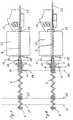
- FIG. 1shows a preferred embodiment of a Device according to the invention for removing an analytical Consumables from a not shown in Fig. 1 Storage container that the invention Idea of a position-dependent feed force using a mechanical cam control realized and advantageous for use in very small, battery operated Analyzers is suitable.
- the devicecomprises an electric drive motor 1 whose driving force transmitted to a drive wheel 3 via a transmission 2 becomes.
- the drive wheel 3is the driver pin 4th a cylindrical, helically wound transport spiral 5 non-rotatably connected.
- the transport spiral 5is rotatable at its other end in a pivot bearing 6 stored and can rotate by their drive Longitudinal axis are offset.
- the transport spiral 5serves as a control element mechanical path or curve control and points Sections of different slopes.
- sheconsists for example made of spring steel, since they are made of this material can be produced advantageously.
- a certain elastic Compliancycan in some applications may be appropriate, but is not mandatory. In most applications it will be useful the transport helix 5 from a relatively hard, little elastic spring steel as rigid as possible, i.e. with a high spring constants (spring rate).
- the transport spiral 5is axially by a plunger 7 permeated.
- the plunger 7is in the starting position shown in which he is completely in the transport spiral 5 is withdrawn.
- the plunger 7 from the transport helix 5in the pushed out the arrow 8 marked direction.
- the plunger 7a driver part 9, which is rotatable and fixed with the plunger 7 connected receptacle 10 and a driver pin arranged on the receiving socket 10 11 includes.
- the outer dimensions of the receptacle 10are so small that they are in the axial direction through the transport spiral 5 can be moved.
- the driver pin 11is preferred essentially transverse to the longitudinal direction of the Transport helix 5, i.e. transverse to the feed direction of the Tappet 7 arranged.
- the driver pin 11is in one Carrier guide 12, which is parallel to the Ram 7 extends.
- Driving pin 11When the transport helix 5 is rotating by the drive their windings exert a force on the Driving pin 11 out.
- This forceconsists of one Component that the driving pin 11 around the plunger 7th rotates, and a component that the driving pin 11 in Direction of the plunger 7 moves together.
- the rotary motion the driver pin 11is through the driver guide 12 prevented or in special embodiments performed so that the remaining force component the Ram 7 promotes through the transport spiral 5.
- the axial dimensions the receptacle 10are so large that they are always safe between the turns and does not jam can.
- the length of the measured in the axial direction Receiving socket 10should therefore at least expediently as large as half the maximum distance between two turns the transport helix 5. In this case it is sufficient it when the plunger 7 in the forward direction in a socket 13 is guided; then the guide at the back end through the transport spiral 5 and the axially displaceable therein Receiving socket 10 causes.
- the Tappet 7 at another pointfor example is stored at its rear end. This can be done, for example the plunger 7 have an axial cavity, in which engages a guide mandrel from its rear end.
- another guide elementmay also be provided.
- the transport spiral 5inside or serve outside supporting, longitudinally slotted sleeve.
- the If necessary, the sleevecan also function as a carrier guide 12 meet.
- the driver guide 12can refer to the rotational position of the plunger 7 its longitudinal axis easily and precisely defined or to be controlled. This is special, for example important when the front end of the plunger 7 is in shape a blade 14 is formed, which may be advantageous can to the film of a storage container without or to penetrate only with little formation of snippets. It can then be important that the plunger 7 in one certain orientation to that from the storage container analytical consumables to be removed is to to ensure safe transport. For example should be in the case of strip-shaped test elements Blade 14 approximately perpendicular to the plane of the test strips stand to ensure safe funding.
- the defined orientation of the plunger 7 or the blade 14 on the analytical consumable to be removedis effected by the driver guide 12. It is even possible, this relative positioning as a function of To vary the transport route. If the driver guide 12 is straight, the plunger 7 rotates during of its feed not. If, on the other hand, the driver guide 12 is wound in the axial direction, rotates the plunger 7 into the respective through the driver guide 12th given location.
- the direction of movement of the plunger 7also reverses around.
- a short phaseoccur in which the transport spiral 5 rotates without that the plunger 7 is moved. This phase ends as soon as another turn of the transport spiral 5 on the driver pin 11 is present and causes its displacement.
- the the resulting short dead timeis not in practice annoying and can possibly by appropriate training the coupling between driver pin 11 and transport spiral 5 can be reduced or prevented.
- the Driving pin 11 at the front or rear end of the Operate the transport coil 5 arrangedlimit switch to to end the transport process at the end of the transport route.
- the transport spiral 5has different lengths Inclines on. This makes it possible for the Ram 7 exerted feed force and the feed speed of the plunger 7 depending on its axial displacement position to vary, even if the Transport helix 5 with a substantially constant Speed rotates. In the sections with a slight slope, in which the turns of the transport spiral 5 are close together, the feed force high and the feed rate slow. In the Sections in which the transport spiral 5 has a high Inclines and their turns a large distance the feed force is low and the feed speed high.
- the drive motor 1 during the feed movement of the plunger 7 loaded much more evenly than if the transport helix 5 has an even slopewould have.
- the battery the deviceis loaded more evenly, which means more Energy can be extracted as harmful current peaks are avoided become.
- the drive motor 1can an optimal working point can be designed so that energy efficiency improves. Total results This measure also means that the movement of the Ram 7 required for the removal of a consumable Total time is reduced.
- the varying slope of the transport spiral 5has an effect the result is like a travel-dependent gearbox that acting on the plunger 7 during its feed movement Load changes that depend on the device the feed path are predetermined, are compensated in such a way that the drive motor 1 is substantially uniform is charged.
- Fig. 2shows a cross section through an inventive Contraption.
- the transport spiralis shown 5, the receptacle 10 and the driving pin 11 in a straight-line driver guide 12.
- the Driver guide 12is in the example shown in Formed a groove in a block.
- Other embodiments with which the position of the driving pin 11thare determined by a person skilled in the art in a simple manner to realize.
- Fig. 2is also the recording and positioning device 19 shown for receiving a storage container, the seventeen chambers with analytical consumables having.
- the receiving devicecomprises 19 seventeen through holes 15 in one Perforated disk 41 positioned in front of the plunger 7 and through which the plunger 7 can be guided.
- a guide pin 16which is in a central Bore of the storage container engages.
- the receiving device 19To rotate the receiving device 19 is a not shown Drive provided, positioning by means of a positioning disk 17 and electrical Sliding contacts 18 takes place.
- the storage containercan be opened have an evaluation code on the outside, which is automatic can be read.
- the guide pin 16engages in a corresponding measuring device into the central hole of the storage container and keep it in the correct position for removal of consumables.
- Can at the edge of the central hole there is, for example, a drive sprocket on the storage containerare in a correspondingly shaped Counterpart when using the storage container in a Analyzer can intervene and with its help Storage container is rotated in the device.
- Storage containeris rotated in the device.
- the piercing openings 15are circular, since the Shank of the plunger 7 preferably a circular one Has cross section. However, this does not necessarily apply also for the removal opening or insertion opening in the storage container, which is closed by a film are. To keep their area as small as possible these openings are often not circular but point a different form. For example, with test strips an elliptical or other elongated shape is advantageous, the longitudinal extension in the direction of Test strip level.
- FIG. 5corresponds to the embodiment according to FIG. 1, in which the Transport helix 5 runs past the driving pin 11, so that when the direction of rotation of the transport spiral is reversed 5 the transport helix 5 is only rotated a little must be before the plunger 7 is moved back.
- the transport spiral 5passed through an opening in the driver pin 11, which causes the dead path when reversing the rotary motion is reduced.
- a modified embodimentcan for example also be provided that on the Transport helix 5 arranged a sliding liner is articulated to the driving pin 11 is.
- FIG. 5 to 8illustrate different phases when operating the device according to the invention Fig. 1.
- the transport spiral 5is shown with Ram 7, the receiving device 19 with guide funnel 20 and a drum-shaped storage container 21 from which from a chamber 42 shown only in FIG. 5 Test element 22 removed and into a measuring device 23 is proceeded.
- the Tappet 7in a correct position relative to the storage container 21 are brought.
- the plunger 7is in a basic position 24 in which he retracted into the transport coil 5 is.
- a storage container 21is in the receiving device 19 used and by means of a positioning device becomes the chamber 42, which is a test element to be removed 22 contains, driven in front of the plunger 7.
- the insertion opening 28 and the opposite removal opening 29 the chamber 42 in which the test element 22 is located,are sealed with a foil.
- the transport spiral 5is then in by means of the drive Rotational movement offset, whereby the plunger 7 forward moved and at the film penetration shown in Fig. 6 25 first pierces the film over the insertion opening 28. Immediately afterwards the film is at the removal opening 29 pierce through the test element 22.
- the plunger 7is further in the storage container 21 pushed in, the test element 22 first conveyed out of the storage container 21 and then in a defined position in the measuring device 23 is positioned.
- the rotational movement of the transport spiral 5be interrupted to carry out the measurement.
- FIG. 10illustrates how the pushing force of a plunger depending on its Position can be realized purely electronically can.
- the control 36takes place by means of a tachometer 37, a controller 38 with target size specification 39 and a pulse width modulated or linear controlled Output 40.
- this schemeis not as efficient like a load-dependent, mechanical transmission, because the Drive motor 1 is not always in an optimal operating point can be held.
Landscapes
- Health & Medical Sciences (AREA)
- Engineering & Computer Science (AREA)
- Biomedical Technology (AREA)
- Life Sciences & Earth Sciences (AREA)
- Chemical & Material Sciences (AREA)
- Physics & Mathematics (AREA)
- Urology & Nephrology (AREA)
- Analytical Chemistry (AREA)
- Chemical Kinetics & Catalysis (AREA)
- Biophysics (AREA)
- Hematology (AREA)
- Molecular Biology (AREA)
- Clinical Laboratory Science (AREA)
- Food Science & Technology (AREA)
- Medicinal Chemistry (AREA)
- Optics & Photonics (AREA)
- Biochemistry (AREA)
- General Health & Medical Sciences (AREA)
- General Physics & Mathematics (AREA)
- Immunology (AREA)
- Pathology (AREA)
- Automatic Analysis And Handling Materials Therefor (AREA)
- Sampling And Sample Adjustment (AREA)
- Analysing Materials By The Use Of Radiation (AREA)
Abstract
Description
Translated fromGermanDie Erfindung betrifft eine Vorrichtung und ein entsprechendesVerfahren zum Entnehmen eines analytischen Verbrauchsmittels,insbesondere eines Testelements, auseinem Vorratsbehältnis, das ein oder mehrere Kammern aufweist.Die Kammern enthalten jeweils ein oder mehrereVerbrauchsmittel und weisen jeweils eine Entnahmeöffnungzum Entnehmen eines Verbrauchsmittels und eine der Entnahmeöffnunggegenüberliegende Einschuböffnung zum Einführeneines Stößels für den Transport des zu entnehmendenVerbrauchsmittels auf. Dabei sind die Entnahmeöffnungund die Einschuböffnung zur Lagerung des Verbrauchsmittelsmit einer Folie, die auch als Siegelfolie bezeichnetwird, verschlossen. Zur Entnahme eines Verbrauchsmittelswird ein Stößel mittels einer Antriebseinheit verschobenund das Verbrauchsmittel durch den Stößel aus der Kammerin dem Vorratsbehältnis herausbefördert.The invention relates to a device and a correspondingMethod for removing an analytical consumable,especially a test elementa storage container that has one or more chambers.The chambers each contain one or moreConsumables and each have a removal openingfor removing a consumable and one of the removal openingopposite insertion opening for insertiona pestle for the transport of the to be removedConsumable on. Here are the removal openingand the insertion opening for storing the consumablewith a film, also known as a sealing filmis closed. To remove a consumablea plunger is moved by means of a drive unitand the consumable through the plunger from the chambertransported out in the storage container.
Für die chemische und biochemische Analyse von festen undflüssigen Probenmaterialien haben sich in darauf spezialisiertenLabors und insbesondere auch für den Einsatzaußerhalb fester Labors trägergebundene Schnelltestsetabliert. Solche trägergebundenen Schnelltests basieren auf einer eigens entwickelten Trockenchemie und sindtrotz der oftmals komplexen Reaktion unter Beteiligungempfindlicher Reagenzien selbst von Laien einfach undunkomplziert durchzuführen.For the chemical and biochemical analysis of solid andliquid sample materials have specialized in itLaboratories and especially for useoutside of fixed laboratories, carrier-bound rapid testsestablished. Such carrier-based rapid tests are basedon a specially developed dry chemistry and aredespite the often complex response with participationsensitive reagents even by laypeople andeasy to carry out.
Ein bekanntes Beispiel für trägergebundene Schnelltestssind Testelemente für die Bestimmung des Blutglucosegehaltesbei Diabetikern. Diagnostische Testelemente, diestreifenförmig ausgebildet sind, werden auch als Teststreifenbezeichnet. Bekannte Ausführungsformen sind z.B.Ein- oder Mehrfelderteststreifen für die Urinanalytik unddiverse Indikatorpapiere. Da neben Testelementen inStreifenform auch andere Formen trägergebundener Testsexisitieren, spricht man allgemeiner von analytischenTestelementen.A well-known example of carrier-based rapid testsare test elements for the determination of the blood glucose contentin diabetics. Diagnostic test elements thatstrips are also used as test stripsdesignated. Known embodiments are e.g.Single or multi-field test strips for urine analysis andvarious indicator papers. In addition to test elements inStrip shape also other forms of carrier-bound testsexist, one speaks more generally of analyticalTest elements.
Analytische Testelemente in dem erfindungsgemäßen Zusammenhangsind visuell oder apparativ auswertbar. Apparativauswertbare Testelemente sind beispielsweise optisch,insbesondere photometrisch auswertbare Testelemente oderelektrochemische Sensoren und dergleichen mehr. Derartigeanalytische Testelemente sind, wie andere analytischeVerbrauchsmittel, in einem Vorratsbehältnis verpackt, umsie vor schädlichen Umwelteinflüssen wie z.B. Licht,Feuchtigkeit oder mechanischer Einwirkung zu schützenoder unter sterilen Bedingungen aufzubewahren. Zu denanalytischen Verbrauchsmitteln zählen neben den Testelementenbeispielsweise auch Lanzetten oder Probennahmeelemente.Analytical test elements in the context of the inventioncan be evaluated visually or by equipment. Apparativeevaluable test elements are, for example, optical,in particular test elements which can be evaluated photometrically orelectrochemical sensors and the like. Suchanalytical test elements are like other analytical onesConsumables, packed in a storage container, in orderagainst harmful environmental influences such as Light,Protect moisture or mechanical influencesor stored under sterile conditions. To theanalytical consumables count alongside the test elementsfor example also lancets or sampling elements.
Da derartige analytische Verbrauchsmittel im Stand derTechnik umfassend beschrieben und dem Fachmann in einerVielzahl von Ausführungsformen geläufig sind, erübrigtsich hier eine detaillierte Beschreibung. Statt dessensei beispielsweise auf folgende Dokumente verwiesen: DE-A 19753847.9, EP-A 0138152, EP-A 0821233, EP-A 0821234, EP-A0630609, EP-A 0565970 und WO 97/02487.Since such analytical consumables in the state of theTechnology described extensively and the expert in oneVariety of embodiments are common, superfluousa detailed description here. InsteadPlease refer to the following documents, for example: DE-A19753847.9, EP-A 0138152, EP-A 0821233, EP-A 0821234, EP-A0630609, EP-A 0565970 and WO 97/02487.
Analytische Verbrauchsmittel werden in einem Vorratsbehältnisaus einem starren Material gelagert, um sie vorder Einwirkung von Lichtstrahlen, dem Zutritt von Luftfeuchtigkeit,Schmutz, Keimen und Staub sowie vor mechanischerBeeinträchtigung zu schützen. Wenn das Vorratsbehältnismehrere Verbrauchsmittel enthält, sind diese zumeistin einzelnen Kammern untergebracht, wobei die Kammernjeweils ein oder mehrere Verbrauchsmittel enthaltenkönnen. Es können in einem Vorratsbehältnis auch verschiedeneArten analytischer Verbrauchsmittel, z.B. Testelementeund Lanzetten, in jeweils eigenen Kammern enthaltensein.Analytical consumables are kept in a storage containermade of a rigid material to keep them in frontthe effect of light rays, the entry of air humidity,Dirt, germs and dust as well as mechanicalTo protect impairment. If the storage containercontains several consumables, these are mostlyhoused in individual chambers, the chamberseach contain one or more consumablescan. There can also be several in one storage containerTypes of analytical consumables, e.g. Test elementsand lancets, each in their own chambershis.
Zur Entnahme eines Verbrauchsmittels wird eine der Kammerngeöffnet, wobei die Entnahmeöffnung und die Einschuböffnungverschließende Folien geöffnet werden. Aufdiese Weise ist es möglich, bedarfsweise Verbrauchsmittelaus Kammern zu entnehmen, ohne die anderen Kammern zuöffnen, so daß die in den ungeöffneten Kammern enthaltenenVerbrauchsmittel weiter sicher gelagert werden können.One of the chambers is used to remove a consumableopened, the removal opening and the insertion openingsealing foils are opened. Onthis way it is possible to use consumablescan be removed from chambers without closing the other chambersopen so that the contained in the unopened chambersConsumables can be stored safely.
Die Vorratsbehältnisse und Kammern können in verschiedenerWeise ausgestaltet sein und enthalten in vielen Fälleneinen Trockenmittelvorrat, um den Schutz vor Feuchtigkeitzu erhöhen. Die Vorratsbehältnisse können miteinem Datenträger, beispielsweise einem Etikett in lesbarerSchrift, einem Strichcode-Etikett oder einem Magnetstreifenversehen sein, auf dem chargenspezifische Datenund ggf. weitere Informationen zu dem analytischen Verbrauchsmittelgespeichert und abrufbar sind.The storage containers and chambers can be in differentBe designed and contain in many casesa desiccant supply to protect against moistureto increase. The storage containers can witha data carrier, for example a label in readableWriting, a barcode label or a magnetic stripebe provided on which batch-specific dataand possibly further information on the analytical consumableare stored and available.
Die analytischen Verbrauchsmittel können manuell odervorzugsweise durch eine mechanische Vorrichtung aus demVorratsbehältnis entnommen werden, wobei die in dem Vorratsbehältnisin ungeöffneten Kammern verbleibenden Verbrauchsmitteldurch die Einzelversiegelung mittels derFolie weiterhin geschützt sind. Die Entnahme der Verbrauchsmittelerfolgt durch Herausschieben aus der Kammermit Hilfe eines Stößels.The analytical consumables can be manually orpreferably by a mechanical device from theStorage container can be removed, being in the storage containerConsumables remaining in unopened chambersthrough the individual sealing by means of theFoil are still protected. The removal of the consumablesis done by pushing it out of the chamberwith the help of a pestle.
Vorratsbehältnisse für analytische Verbrauchsmittel unddie entsprechenden Vorrichtungen zum Entnehmen der Verbrauchsmittelsind im Stand der Technik umfangreichbeschrieben und dem Fachmann in einer Vielzahl von Ausführungsformengeläufig. In diesem Zusammenhang wird beispielsweiseauf folgende Dokumente verwiesen: EP-A0622119, EP-A 0732590, EP-A 0738666, US 5,489,414, US5,510,266, US 5,720,924 und insbesondere US 5,632,410sowie DE-A 19854316.Storage containers for analytical consumables andthe corresponding devices for removing the consumablesare extensive in the prior artdescribed and the skilled person in a variety of embodimentscommon. In this context, for examplereferred to the following documents: EP-A0622119, EP-A 0732590, EP-A 0738666, US 5,489,414, US5,510,266, US 5,720,924 and in particular US 5,632,410and DE-A 19854316.
Die Vorratsbehältnisse, die auch als Magazine bezeichnetwerden, sind zumeist für den Einsatz in Meßgeräten, insbesonderein kompakten Meßgeräten konzipiert. Für dieAufnahme eines Vorratsbehältnisses in ein Meßgerät, indem mit Hilfe eines Stößels ein Verbrauchsmittel aus demVorratsbehältnis entnommen wird, können entsprechendeMittel, insbesondere zum genauen Positionieren des Vorratsbehältnissesrelativ zu funktionalen Bestandteileneines Analysegerätes und hierbei insbesondere zum Stößelfür die Verbrauchsmittelentnahme vorgesehen sein.The storage containers, also known as magazinesare mostly for use in measuring instruments, in particulardesigned in compact measuring devices. For theInclusion of a storage container in a measuring device, inwith the help of a plunger a consumable from theStorage container can be removed, correspondingMeans, in particular for the exact positioning of the storage containerrelative to functional componentsof an analysis device and in particular to the pestlebe provided for the consumption of consumables.
Die Entnahme eines Verbrauchsmittels ist in vielen Ausführungsformenautomatisiert, beispielsweise um Fehlbedienungenauszuschließen oder um die Bedienungsfreundlichkeitzu erhöhen. In diesen Fällen wird der die Entnahmeeines Verbrauchsmittels bewirkende Stößel mittels einer Antriebseinheit, die einen elektrischen Antriebsmotorund eventuell ein Getriebe umfaßt, bewegt. Beispielekonventioneller manueller, motorischer und automatisierterVorrichtungen zum Entnehmen analytischer Verbrauchsmittelaus Vorratsbehältnissen sind in den oben genanntenDokumenten beschrieben.The removal of a consumable is in many embodimentsautomated, for example to avoid incorrect operationexclude or to ease of useto increase. In these cases, the removala plunger causing a consumablea drive unit that has an electric drive motorand possibly includes a gear. Examplesconventional manual, motorized and automatedDevices for removing analytical consumablesfrom storage containers are in the aboveDocuments.
Charakteristisch für die Vorratsbehältnisse, auf die sichdie Erfindung bezieht, ist, daß sie an zwei gegenüberliegendenÖffnungen jeweils mit einer Folie verschlossensind, die bei der Entnahme des Verbrauchsmittels durchstoßenwerden müssen. Zunächst dringt der Stößel durchdie Folie über die Einschuböffnung in die Kammer des Vorratsbehältnissesund drückt dort das zu entnehmende Verbrauchsmittelweiter. Anschließend wird durch das in Vorschubrichtungvordere Ende des Verbrauchsmittels dieFolie über der Entnahmeöffnung nach außen hin aufgerissenund das Verbrauchsmittel aus der Kammer herausgeschobenbzw. in eine Gebrauchsstellung gebracht. Dieser Transportvorgangbringt es mit sich, daß in Teilbereichen desTransportweges relativ hohe Kräfte benötigt werden (z.B.beim Durchstoßen der beiden Folien oder beim Plaziereneines Testelements in einer vorgegebenen Position einerMeßhalterung), wogegen auf dem übrigen Transportweg nureine relativ geringe Vorschubkraft benötigt wird.Characteristic of the storage containers on which it relatesthe invention relates is that it faces two oppositeEach opening is closed with a filmthat penetrate when the consumable is removedNeed to become. First, the plunger gets throughthe film through the insertion opening into the chamber of the storage containerand presses the consumable to be removed therefurther. Then the in the feed directionfront end of the consumable theTear the film over the opening to the outsideand pushed the consumable out of the chamberor brought into a position of use. This transportation processbrings with it that in parts of theRelatively high forces are required (e.g.when piercing the two foils or when placinga test element in a predetermined positionMeasuring bracket), whereas on the rest of the transport route onlya relatively low feed force is required.
Die Auswahl für Material und Dicke der Folien, die zumVerschließen der Öffnungen der Kammern des Vorratsbehältnissesdienen, ist durch zwei Erfordernisse eingeschränkt.Einerseits müssen sie hinreichend fest sein, umeinen ausreichenden Schutz zu bieten und keine mechanischeSchwachstelle bei der Handhabung des Vorratsbehältnissesdarzustellen. Andererseits darf die Folie nicht zufest sein, damit sie durch den Stößel bzw. durch das analytische Verbrauchsmittel durch den von der Vorschubkraftdes Stößels ausgehenden Druck durchtrennt werden kann.The selection for material and thickness of the foils, which forClosing the openings of the chambers of the storage containerserve is limited by two requirements.On the one hand, they have to be sufficiently firm toto provide adequate protection and not mechanicalWeakness in the handling of the storage containerto represent. On the other hand, the film must notbe firm so that it can be pushed through the pestle or through theConsumables by the of the feed forceof the tappet can be severed.
Inbesondere in kleinen, kompakten Analysegeräten, diebatteriebetrieben sind, bestehen zudem die widersprüchlichenAnforderungen, daß einerseits die Geschwindigkeit,mittels der die Entnahme eines Verbrauchsmittels, insbesondereeines Testelements durchgeführt wird, hoch seinsoll und andererseits der damit verbundene Batterieverbrauchgering sein soll, um mit einem Batteriesatz möglichstviele Messungen durchführen zu können.Especially in small, compact analyzers thatare battery operated, there are also contradicting onesRequirements that on the one hand the speed,by means of the removal of a consumable, in particularof a test element is highshould and on the other hand the associated battery consumptionshould be as low as possible with one battery packto be able to carry out many measurements.
Nach dem Stand der Technik werden diese technischen Problemehinsichtlich der aufzubringenden Kraft, der Schnelligkeitder Verbrauchsmittelentnahme und des Energiebedarfsdadurch gelöst, daß die Antriebseinheit eine resultierendekonstante Vorschubkraft des Stößels erzeugt, diesich aus der Motorkraft des Antriebsmotors und einereventuellen Getriebeübersetzung ergibt und die hoch genugist, um die im Transportweg auftretenden Lastspitzen zubewältigen. Ob dies durch die Wahl eines kräftigeren Antriebsmotorsmit entsprechend höherem Batterieverbrauchoder durch die Wahl einer anderen Getriebeübersetzunggeschieht, ist von der jeweiligen Auslegung abhängig,d.h. davon, ob eine rasche Meßfolge oder ein geringerGesamtbatterieverbrauch wichtiger ist.These technical problems arise according to the prior artin terms of the force to be exerted, the speedthe consumption of consumables and the energy requirementsolved in that the drive unit a resultingproduces constant pushing force of the ramitself from the engine power of the drive motor and onepossible gear ratio results and high enoughis to increase the load peaks occurring in the transport routedeal with. Whether this is by choosing a more powerful drive motorwith a correspondingly higher battery consumptionor by choosing a different gear ratiohappens depends on the respective interpretation,i.e. whether a rapid measurement sequence or a small oneTotal battery consumption is more important.
Der Antrieb wird nach dem Stand der Technik somit nachder maximal auftretenden Last ausgelegt und zwischen denbeiden Extremen minimaler Energieverbrauch und maximaleTransportzeit einerseits oder maximaler Energieverbrauchund minimale Transportzeit andererseits optimiert. Inkeinem Fall wird jedoch nach dem Stand der Technik einewirklich optimale Lösung erzielt, da der Antrieb überweite Strecken des Vorschubweges des Verbrauchsmittels dadurch, daß er auf die maximal auftretende Last ausgelegtist, überdimensioniert ist und in diesem Bereich jenach Auslegung die Anforderungen hinsichtlich Schnelligkeitund Energieverbrauch nicht beide optimal erfüllenkann.The drive is thus according to the state of the artthe maximum load occurring and between theboth extremes of minimal energy consumption and maximumTransport time on the one hand or maximum energy consumptionand minimal transport time on the other hand optimized. Inin no case, however, according to the prior artreally achieved optimal solution because the drive overlong distances of the feed path of the consumablein that it is designed for the maximum occurring loadis oversized and ever in this areathe design requirements for speedand energy consumption do not optimally meet bothcan.
Ausgehend von diesem Stand der Technik liegt der Erfindungdie Aufgabe zugrunde, eine eingangs genannte Vorrichtungzum Entnehmen eines analytischen Verbrauchsmittels,insbesondere eines Testelements, aus einem Vorratsbehältnissowie ein entsprechendes Verfahren dahingehendzu verbessern, daß die Anforderungen hinsichtlich Schnelligkeitder Entnahme des Verbrauchsmittels sowie derMinimierung eines damit verbundenen Energieverbrauchsgleichzeitig verbessert werden, insbesondere bei sehrkompakter Bauweise einer entsprechenden Vorrichtung.The invention is based on this prior artthe task is based on a device mentionedto remove an analytical consumable,in particular a test element, from a storage containeras well as a corresponding procedureto improve the speed requirementsthe removal of the consumable and theMinimize the associated energy consumptionbe improved at the same time, especially at verycompact design of a corresponding device.
Zur Lösung dieser Aufgabe bei der eingangs genannten Vorrichtungbzw. bei einem entsprechenden Verfahren wirdvorgeschlagen, daß die Größe der Vorschubkraft, die vondem Stößel bei seiner der Entnahme eines Verbrauchsmittelsdienenden Vorschubbewegung ausgeübt wird, in Abhängigkeitvon der Position des Stößels gesteuert wird. DerGrundgedanke der vorliegenden Erfindung kann somit daringesehen werden, daß die beiden genannten widersprüchlichenAnforderungen hinsichtlich schneller Entnahme undgeringem Energieverbrauch gleichzeitig dadurch optimiertwerden können, daß ein Stößelantrieb verwendet wird, dessenVorschubkraft sich in Abhängigkeit von dem Vorschubweglastangepaßt ändert.To solve this problem in the device mentionedor with a corresponding proceduresuggested that the magnitude of the feed force be fromthe plunger when removing a consumableserving feed movement is exercised, dependingis controlled by the position of the plunger. TheThe basic idea of the present invention can thus be found thereincan be seen that the two mentioned contradictoryRapid Withdrawal Requirementslow energy consumption optimized at the same timecan be that a tappet drive is used, theFeed force depends on the feed pathload-adjusted changes.
Im Rahmen der vorliegenden Erfindung wurde überraschenderweisefestgestellt, daß die außerordentlich schwierigenAnforderungen bei Vorrichtungen zum Entnehmen einesanalytischen Verbrauchsmittels aus Vorratsbehältnissen mit einem Stößel, dessen Vorschubkraft sich als Funktiondes Vorschubweges ändert, gelöst werden können. Fernerhat sich gezeigt, daß eine solche weg- bzw. ortsabhängigeVorschubkraft mit einfachen Mitteln gelöst werden kann,so daß die gesamte Entnahme gleichzeitg hinsichtlichbeider Anforderungen betreffend Geschwindigkeit und Energieaufwandoptimiert werden kann und nicht, wie es bisherfür erforderlich gehalten wurde, nur jeweils hinsichtlicheiner Anforderung bzw. im Wege einer Kompromißlösung.In the context of the present invention, surprisinglyfound that the extremely difficultDevice removal requirementsanalytical consumables from storage containerswith a plunger, the feed force of which functionsof the feed path changes, can be solved. Furtherhas been shown that such a path or locationFeed force can be released with simple means,so that the entire withdrawal at the same timeboth requirements regarding speed and energy consumptioncan be optimized and not as it has been so farwas deemed necessary, only with regard toa requirement or a compromise solution.
Vergleichsversuche haben beispielsweise ergeben, daß einkonventioneller Antrieb, der auf Energieeinsparung optimiertist, eine Transportzeit zur Entnahme eines Teststreifensaus einem trommelförmigen Magazin 20 sec benötigtund mit einem batteriebetriebenen Meßgerät mehr als500 Teststreifen gemessen werden können. Wenn der Antriebdagegen auf eine schnelle Geschwindigkeit der Entnahmeoptimiert wird, wobei die Transportzeit ca. 4 sec beträgt,können nur 50 Teststreifen pro Batteriesatz gemessenwerden. Mit einer erfindungsgemäß ausgebildeten Vorrichtungdagegen liegt die Transportzeit zwischen 4 und 5sec, wobei ebenfalls mehr als 500 Teststreifen je Batteriesatzgemessen werden können.Comparative tests have shown, for example, that aconventional drive that optimizes for energy savingis a transport time for the removal of a
Mit der Erfindung werden somit Ziele erreicht, um die dieFachwelt sich schon lange bemüht hat. Ferner sind dieBeschränkungen hinsichtlich des Materials und der Dickeder Folien bei einer erfindungsgemäßen Vorrichtung wenigerbedeutsam, so daß kostengünstigere oder für denjeweiligen Einsatzzweck geeignetere Materialien in einergrößeren Auswahl zur Verfügung stehen.With the invention, goals are achieved to which theExperts have been trying for a long time. Furthermore, theMaterial and thickness restrictionsless of the films in a device according to the inventionsignificant, so that cheaper or for themore suitable materials in a particular applicationmore choices are available.
Um besonders gute Ergebnisse hinsichtlich Schnelligkeitder Entnahme eines Verbrauchsmittels, des damit verbundenenEnergieverbrauchs sowie hinsichtlich der konstruktiven Erfordernisse und der damit verbundenen Kosten zugewährleisten, werden bevorzugt die nachfolgenden Maßnahmeneinzeln oder in Kombination miteinander eingesetzt.For particularly good results in terms of speedthe removal of a consumable, the associatedEnergy consumption as well as in terms of constructiveRequirements and the associated costsguarantee, the following measures are preferredused individually or in combination with each other.
Nach einem ersten bevorzugten Merkmal kann vorgesehensein, daß die Vorschubkraft in Abhängigkeit von dem Vorschubwegsteuerbar ist, den der Stößel zurückgelegt hat.Dabei wird bevorzugt der Vorschubweg relativ zu einemTeil mit einer bezüglich der Vorrichtung festen Postionbestimmt. Dies kann beispielsweise die Anfangspositiondes Stößels, die Endposition des Stößels oder die Lageeiner der Folien sein. Alternativ besteht auch die Möglichkeit,eine absolute Positionsmessung des Stößelsdurchzuführen.According to a first preferred feature can be providedbe that the feed force is dependent on the feed pathis controllable, which the tappet has covered.The feed path is preferred relative to onePart with a fixed position with respect to the devicecertainly. For example, this can be the starting positionof the ram, the end position of the ram or the positionbe one of the slides. Alternatively, there is also the possibilityan absolute position measurement of the ramperform.
Ferner läßt sich die Entnahme eines analytischen Verbrauchsmittelsvorteilhafterweise dadurch verbessern, daßdie Vorschubkraft bei mindestens einem der folgendenBetriebszustände erhöht ist: beim Durchstoßen der Folieüber der Einschuböffnung durch den Stößel, beim Durchstoßender Folie über der Entnahmeöffnung durch das Verbrauchsmittel,beim Positionieren des entnommenen Verbrauchsmittelsin eine vorgegebene Gebrauchslage oderbeim Ausstoßen eines verbrauchten Verbrauchsmittels auseiner vorgegebenen Gebrauchslage.It is also possible to remove an analytical consumableadvantageously improve in thatthe feed force in at least one of the followingOperating conditions is increased: when piercing the filmabove the insertion opening through the plunger when piercingthe film over the removal opening through the consumable,when positioning the removed consumablein a predetermined position of use orwhen expelling a used consumablea predetermined position of use.
Eine Gebrauchslage in diesem Sinne ist jede bestimmte,definierte Position, die ein Verbrauchsmittel für seinenbestimmungsgemäßen Gebrauch einnehmen muß, beispielsweiseder Ort einer Probenaufnahme oder eine Position, in dereine analytische Messung durchgeführt wird. In solchenGebrauchslagen müssen die Verbrauchsmittel in aller Regelgenau positioniert werden, wozu entsprechende Führungenoder Anschlagelemente vorgesehen sind, die eine Erhöhungder zum Transport des Gebrauchsmittel erforderlichen Vorschubkraft zur Folge haben. Allgemein kann gesagt werden,daß mit der erfindungsgemäßen Vorrichtung die Vorschubkraftin den Bereichen, in denen eine erhöhte Last auftritt,beispielsweise in den vorstehend genannten Positionen,erhöht werden kann, wogegen die Vorschubkraft inanderen Bereichen des Vorschubweges des Stößels niedrigerausgelegt werden kann. Dadurch wird insbesondere derEnergieverbrauch minmiert, da nur in solchen Bereichen,in denen der Stößel eine erhöhte Last überwinden muß,eine erhöhte Vorschubkraft zur Verfügung gestellt wird.A position of use in this sense is any particulardefined position that is a consumable for hisintended use, for examplethe location of a sample or a position in whichan analytical measurement is carried out. In suchAs a rule, the consumables must be in positions of usebe positioned exactly, for which purpose guidesor stop elements are provided which increasethe feed force required to transport the consumableshave as a consequence. In general it can be saidthat with the device according to the invention the feed forcein areas where there is an increased load,for example in the above positions,can be increased, whereas the feed force inother areas of the plunger feed path lowercan be interpreted. As a result, theEnergy consumption minimized, since only in such areas,in which the ram has to overcome an increased load,an increased feed force is made available.
Nach einem anderen bevorzugten Merkmal ist die Vorrichtungderart ausgebildet, daß die Vorschubgeschwindigkeitdes Stößels in Bereichen mit erhöhter Vorschubkraft reduziertund in Bereichen mit reduzierter Vorschubkrafterhöht ist. Bei Berücksichtigung dieser Regel läßt sichdie für die Entnahme des Verbrauchsmittels erforderlicheGesamtzeit des Transportes unter Berücksichtigung desdamit verbundenen Energieverbrauchs besonders gut optimieren.According to another preferred feature, the devicedesigned such that the feed rateof the ram is reduced in areas with increased feed forceand in areas with reduced feed forceis increased. Taking this rule into accountthe one required for the removal of the consumableTotal time of transport taking into account theoptimize the associated energy consumption particularly well.
Eine gewünschte Vorschubkraft-Vorschubweg-Charakteristikläßt sich prinzipiell auf rein elektronischem Wege realisieren,wobei die Vorschubbewegung des Stößels mittelseiner elektronischen Regelung der Antriebseinheit gesteuertwird. Hierfür können beispielsweise die Leistung oderdie Drehzahl des Antriebsmotors oder ein regelbaresGetriebe gesteuert werden. Andere Möglichkeiten einerelektronischen Regelung bestehen in der Verwendung vonSchrittmotoren, elektronisch kommutierten Motoren, einerStromregelung des Antriebsmotors oder einer Pulsweitenmodulationdes Antriebsmotors oder ähnlichen Verfahren.A desired feed force-feed path characteristiccan in principle be implemented purely electronically,wherein the feed movement of the ram by meanscontrolled by electronic control of the drive unitbecomes. For example, the performance orthe speed of the drive motor or an adjustableGearboxes can be controlled. Other options oneelectronic regulation consist in the use ofStepper motors, electronically commutated motors, oneCurrent control of the drive motor or pulse width modulationof the drive motor or similar processes.
Elektronische Regelungen können den Vorteil haben, daßdie Vorschubgeschwindigkeit unabhängig von der Betriebsspannung wird, weisen aber in aller Regel den Nachteilauf, daß ein höherer konstruktiver Aufwand erforderlichist und der Antriebsmotor in den meisten Fällen nicht ineinem optimalen Arbeitspunkt gehalten werden kann.Electronic regulations can have the advantage thatthe feed speed regardless of the operating voltageusually have the disadvantageon that a higher design effort is requiredand the drive motor is not in most casesan optimal working point can be maintained.
Nach einem bevorzugten Merkmal der Erfindung wird nämlichvorgeschlagen, daß die Antriebseinheit einen Antriebsmotorumfaßt, der mit einer im wesentlichen konstantenAntriebsleistung und/oder im wesentlichen konstantenDrehzahl betreibbar ist, um eine möglichst optimale Energieausnutzungdadurch zu erzielen, daß die Stromquelle,beispielsweise eine Batterie oder ein Akkumulator,gleichmäßig belastet und der Antriebsmotor bei einemArbeitspunkt mit einem guten Wirkungsgrad betrieben wird.According to a preferred feature of the inventionsuggested that the drive unit be a drive motorcomprises, with a substantially constantDrive power and / or substantially constantThe speed can be operated in order to make the best possible use of energyin that the power source,for example a battery or an accumulator,evenly loaded and the drive motor at oneOperating point is operated with a good efficiency.
Im Rahmen der Erfindung hat sich gezeigt, daß diese Zielebevorzugt erreicht werden, wenn die Vorschubbewegung desStößels mittels einer mechanischen Wegsteuerung, insbesondereeiner mechanischen Kurvensteuerung gesteuertwird. Eine mechanische Wegsteuerung bzw. Kurvensteuerungkann zudem die weiteren Vorteile aufweisen, daß sie konstruktiveinfach und kostengünstig ist, geringe Reibungsverlusteaufweist oder die Transportposition desStößels entlang des Vorschubweges und die Vorschubkraftbzw. die Vorschubgeschwindigkeit in Abhängigkeit von derPosition des Stößels durch eine Wirkverbindung zwischenKurvensteuerung und Stößel realisiert werden können, ohnedaß hierzu wie zumeist bei einer elektronischen Lösungein gesonderter Weg- oder Positionsaufnehmer erforderlichist. Durch eine Wirkverbindung zwischen Weg- bzw.Kurvensteuerung und Stößel kann eine Koppelung zwischenPosition des Stößels und Vorschubkraft bzw. Vorschubgeschwindigkeiterzielt werden.In the context of the invention it has been shown that these goalscan preferably be achieved when the feed movement of theTappet by means of a mechanical path control, in particularcontrolled by a mechanical cam controlbecomes. A mechanical path control or curve controlcan also have the further advantages that they are constructiveis simple and inexpensive, low friction losseshas or the transport position of theRam along the feed path and the feed forceor the feed rate depending on thePosition of the plunger through an active connection betweenCurve control and tappet can be realized withoutthat this is mostly the case with an electronic solutiona separate displacement or position sensor is requiredis. Through an active connection between path orCurve control and tappet can create a coupling betweenPosition of the ram and feed force or feed speedbe achieved.
Eine mechanische Weg- bzw. Kurvensteuerung kann auf verschiedeneWeise ausgebildet sein. Nach einem zusätzlichenvorteilhaften Merkmal kann vorgesehen sein, daß die Weg- bzw.Kurvensteuerung ein schraubenförmig gewundenes,mittels der Antriebseinheit um seine Längsachse in Drehbewegungversetzbares und den Vorschub des Stößels steuerndesSteuerelement umfaßt, das in Verbindung mit einemMitnehmerteil steht, das den Stößel beim Drehen desSteuerelements in Vorschubrichtung bewegt. Auf dieseWeise wird die von der Antriebseinheit erzeugte Rotationdes Steuerelementes in eine lineare Bewegung des Stößelsumgesetzt.A mechanical path or curve control can be differentBe trained. After an additionaladvantageous feature can be provided that the path orCurve control a helically wound,by means of the drive unit about its longitudinal axis in rotary motiondisplaceable and controlling the feed of the ramControl that includes in conjunction with aDriver part stands, which the plunger when turning theControl moved in the feed direction. To thisThe rotation generated by the drive unit becomesof the control element in a linear movement of the plungerimplemented.
Eine konstruktiv einfache Lösung kann dabei nach einemzusätzlichen vorteilhaften Merkmal dann realisiertwerden, wenn sich die Längsachse des Steuerelements inRichtung der Vorschubbewegung des Stößels erstreckt. DerStößel kann dabei parallel neben dem Steuerelement angeordnetsein oder nach einem bevorzugten Merkmal dasSteuerelement axial durchdringen, wodurch eine besonderskompakte Bauweise erzielt wird.A structurally simple solution can be according to oneadditional advantageous feature then realizedbe when the longitudinal axis of the control inDirection of the feed movement of the plunger extends. TheTappet can be arranged parallel to the control elementbe or according to a preferred characteristicPenetrate control axially, creating a specialcompact design is achieved.
Hinsichtlich der Steigung des Steuerelements der Weg- bzw.Kurvensteuerung kann vorgesehen sein, daß dieselängs der schraubenförmigen Windung konstant ist. Indiesem Fall ist zur Erzielung einer ortsabhängigen Vorschubkraftdas Antriebsmoment der Antriebseinheit zusteuern und zur Erzielung einer ortsabhängigen Vorschubgeschwindigkeitdie Drehzahl des Steuerelementes zu variieren.With regard to the slope of the control element, the path orCurve control can be provided that thisis constant along the helical turn. Inthis case is to achieve a location-dependent feed forcethe drive torque of the drive unitcontrol and to achieve a location-dependent feed rateto vary the speed of the control element.
Bevorzugt ist eine Ausführungsform, bei der die Steigungdes Steuerelements längs seiner schraubenförmigen Windungentsprechend einer gewünschten Vorschubkraft- Positionsabhängigkeitdes Stößels variabel ausgebildet ist. In diesem Fall kann nach einem zusätzlichen, besonders vorteilhaftenMerkmal die Drehzahl des Antriebsmotors derAntriebseinheit bzw. die Drehzahl des Steuerelemente beimVorschub des Stößels im wesentlichen konstant sein.An embodiment is preferred in which the slopethe control element along its helical turnaccording to a desired feed force-position dependencythe plunger is variable. Inthis case can be an additional, particularly advantageousFeature the speed of the drive motorDrive unit or the speed of the controls atFeed of the plunger must be essentially constant.
Ein erfindungsgemäßes, schraubenförmig gewundenes Steuerelementkann auf vielfältige Weise realisiert werden.Eine erste vorteilhafte Ausbildung kann darin bestehen,daß das Steuerelement eine zylinderförmige Steuerwalzemit einer auf der Mantelfläche verlaufenden Nut und dasMitnehmerteil einen in die Nut eingreifenden Nutensteinumfaßt. Die Nut definiert eine Vorschubkurve mit dergewünschten Charakteristik. Derartige Konstruktionen sindin Form eines Spindeltriebes für Regalförderzeuge aus demDokument EP-A 0357935 bekannt. Sie sind jedoch für denerfindungsgemäßen Zweck, insbesondere für kompakte Analysegeräte,relativ groß.An inventive helically wound control elementcan be implemented in a variety of ways.A first advantageous training can consist inthat the control is a cylindrical control rollerwith a groove running on the lateral surface and thatDriver part a sliding block engaging in the grooveincludes. The groove defines a feed curve with thedesired characteristic. Such constructions arein the form of a spindle drive for shelf conveyors from theDocument EP-A 0357935 known. However, they are for thepurpose according to the invention, in particular for compact analysis devices,relatively large.
Besonders bevorzugt ist daher die Realisierung einesschraubenförmig gewundenen Steuerelements in Form einerzylindrischen, schraubenförmig gewundenen Transportwendel,wobei das Mitnehmerteil als in die Windungen derTransportwendel eingreifender Mitnehmerstift ausgebildetist. Beim Drehen der Transportwendel wird entsprechendder Steigung der Transportwendel und der Drehgeschwindigkeitder Mitnehmerstift in axialer Richtung der Transportwendeltransportiert. Der Mitnehmerstift steht inWirkverbindung mit dem Stößel, so daß der Stößel je nachDrehrichtung der Transportwendel vor- oder zurückbewegtwird, wobei die Vorschubkraft und die Vorschubgeschwindigkeitdurch die Transportwendel bestimmt werden. Aufdiese Weise kann eine konstruktiv besonders unaufwendigeerfindungsgemäße Vorrichtung realisiert werden.It is therefore particularly preferred to implement onehelically wound control in the form of acylindrical, helically wound transport spiral,the driver part as in the turns of theCarrier pin engaging the transport spiralis. When turning the transport helix is accordinglythe slope of the transport spiral and the speed of rotationthe driving pin in the axial direction of the transport spiraltransported. The driver pin is inActive connection with the plunger, so that the plunger depending onDirection of rotation of the transport spiral is moved forward or backwardbeing, the feed force and the feed speedbe determined by the transport spiral. Onthis can be a structurally particularly complexdevice according to the invention can be realized.
Ein erfindungsgemäßes Analysegerät zur Analyse einermedizinischen Probe mittels eines medizinischen Verbrauchsmittels,insbesondere zur Durchführung einer Analysemittels eines Testelements, ist dadurch gekennzeichnet,daß es eine erfindungsgemäße Vorrichtung zumEntnehmen eines analytischen Verbrauchsmittels aus einemVorratsbehältnis aufweist.An analysis device according to the invention for analyzing amedical sample using a medical consumable,especially for performing an analysisby means of a test element, is characterizedthat there is an inventive device forWithdraw an analytical consumable from aHas storage container.
Besonders vorteilhaft ist die erfindungsgemäße Vorrichtungin solchen Analysegeräten einsetzbar, die netzunabhängigbetrieben werden können, beispielsweise mittelsBatterien oder Akkumulatoren. In solchen Geräten kann dieErfindung zur Lösung der Aufgabe, mit dem knappen Energievorratder Batterien bzw. des Stromspeicherelementseine maximale Anzahl von analytischen Verbrauchsmittelnzu transportieren, besondere Vorteile bieten. Fernerkönnen Anforderungen hinsichtlich der Begrenzung desStromes, optimierte Fahrzeiten des Stößels oder einesgeringen Platzbedarfs berücksichtigt und erfüllt werden,wobei die Herstellungskosten niedrig sind.The device according to the invention is particularly advantageouscan be used in such analyzers that are network-independentcan be operated, for example by means ofBatteries or accumulators. In such devices, theInvention to solve the problem with the scarce energy supplythe batteries or the power storage elementa maximum number of analytical consumablesto transport, offer special advantages. Furthermay have requirements regarding the limitation of theCurrent, optimized travel times of the tappet or onesmall space requirements are taken into account and fulfilled,the manufacturing cost is low.
Die folgenden Ausführungsbeispiele der Erfindung lassenweitere vorteilhafte Merkmale und Besonderheiten erkennen,die anhand der Darstellung in den Zeichnungen imfolgenden näher beschrieben und erläutert werden. Eszeigen:
- Fig. 1
- einen Längsschnitt durch eine erfindungsgemäßeVorrichtung,
- Fig. 2
- einen Querschnitt durch die Vorrichtung derFig. 1,
- Fig. 3
- einen Einzelheit zu Fig. 1,
- Fig. 4
- eine Abwandlung zu Fig. 3,
- Fig. 5
- die Vorrichtung der Fig. 1 in einer Grundstellung,
- Fig. 6
- die Vorrichtung der Fig. 1 beim Durchstoßeneiner Folie,
- Fig. 7
- die Vorrichtung der Fig. 1 beim Verfahren einesTestelements in eine Meßposition,
- Fig. 8
- die Vorrichtung der Fig. 1 beim Auswerfen desTestelements,
- Fig. 9
- eine Wegdiagramm zu
den Figuren 5bis 8 und - Fig. 10
- ein Blockschaltbild einer erfindungsgemäßenVorrichtung mit elektronischer Regelung.
- Fig. 1
- a longitudinal section through a device according to the invention,
- Fig. 2
- 2 shows a cross section through the device of FIG. 1,
- Fig. 3
- a detail of Fig. 1,
- Fig. 4
- a modification to Fig. 3,
- Fig. 5
- 1 in a basic position,
- Fig. 6
- 1 when piercing a film,
- Fig. 7
- 1 when moving a test element into a measuring position,
- Fig. 8
- 1 when ejecting the test element,
- Fig. 9
- a path diagram to Figures 5 to 8 and
- Fig. 10
- a block diagram of an inventive device with electronic control.
Die Fig. 1 zeigt eine bevorzugte Ausführungsform einererfindungsgemäßen Vorrichtung zum Entnehmen eines analytischenVerbrauchsmittels aus einem in Fig. 1 nicht dargestelltenVorratsbehältnis, die die erfindungsgemäßeIdee einer positionsabhängigen Vorschubkraft mittelseiner mechanischen Kurvensteuerung realisiert und vorteilhaftfür den Einsatz in sehr kleinen, batteriebetriebenenAnalysegeräten geeignet ist. Die Vorrichtung umfaßteinen elektrischen Antriebsmotor 1, dessen Antriebskraftüber ein Getriebe 2 auf ein Antriebsrad 3 übertragenwird. Mit dem Antriebsrad 3 ist der Mitnehmerzapfen 4einer zylindrischen, schraubenförmig gewundenen Transportwendel5 drehfest verbunden. Die Transportwendel 5ist an ihrem anderen Ende in einem Drehlager 6 drehbargelagert und kann durch den Antrieb in Drehung um ihreLängsachse versetzt werden.1 shows a preferred embodiment of aDevice according to the invention for removing an analyticalConsumables from a not shown in Fig. 1Storage container that the inventionIdea of a position-dependent feed force usinga mechanical cam control realized and advantageousfor use in very small, battery operatedAnalyzers is suitable. The device comprisesan
Die Transportwendel 5 dient als Steuerelement einermechanischen Weg- bzw. Kurvensteuerung und weistAbschnitte unterschiedlicher Steigung auf. Sie bestehtbeispielsweise aus Federstahl, da sie aus diesem Materialvorteilhaft herstellbar ist. Es ist jedoch nicht erforderlich,daß die Transportwendel 5 zwischen dem Antriebsrad3 und dem Drehlager 6 unter einer Zug- oder Druckspannungsteht oder daß sie bei ihrer Funktion eine elastische Federkraft ausübt. Eine gewisse elastischeNachgiebigkeit kann zwar in manchen Anwendungsfällenzweckmäßig sein, ist jedoch nicht zwingend erforderlich.In den meisten Anwendungsfällen wird es zweckmäßig sein,die Transportwendel 5 aus einem relativ harten, wenigelastischen Federstahl möglichst starr, d.h. mit einerhohen Federkonstanten (Federrate) auszubilden.The
Die Transportwendel 5 wird axial von einem Stößel 7durchdrungen. In der Fig. 1 ist der Stößel 7 in der Ausgangsstellungdargestellt, in der er ganz in die Transportwendel5 zurückgezogen ist. Zum Entnehmen eines analytischenVerbrauchsmittels aus einem Vorratsbehältniswird der Stößel 7 aus der Transportwendel 5 in der durchden Pfeil 8 gekennzeichneten Richtung herausgeschoben. Umdabei die Drehbewegung der Transportwendel 5 in die Linearbewegungdes Stößels 8 umzusetzen, weist der Stößel 7ein Mitnehmerteil 9 auf, das eine dreh- und verschiebefestmit dem Stößel 7 verbundene Aufnahmebuchse 10 undeinen an der Aufnahmebuchse 10 angeordneten Mitnehmerstift11 umfaßt.The
Die Außenabmessungen der Aufnahmebuchse 10 sind so klein,daß sie in axialer Richtung durch die Transportwendel 5verschoben werden kann. Der Mitnehmerstift 11 ist vorzugsweiseim wesentlichen quer zur Längsrichtung derTransportwendel 5, d.h. quer zur Vorschubrichtung desStößels 7 angeordnet. Der Mitnehmerstift 11 ist in einerMitnehmerführung 12 geführt, die sich parallel zu demStößel 7 erstreckt.The outer dimensions of the
Wenn die Transportwendel 5 durch den Antrieb in Rotationversetzt wird, üben ihre Windungen eine Kraft auf denMitnehmerstift 11 aus. Diese Kraft setzt sich aus einerKomponente, die den Mitnehmerstift 11 um den Stößel 7 dreht, und einer Komponente, die den Mitnehmerstift 11 inRichtung des Stößels 7 bewegt, zusammen. Die Drehbewegungdes Mitnehmerstiftes 11 wird durch die Mitnehmerführung12 unterbunden bzw. in speziellen Ausführungsformengeführt, so daß die verbleibende Kraftkomponente denStößel 7 durch die Transportwendel 5 fördert.When the
Dabei ist es vorteilhaft, wenn die axialen Abmessungender Aufnahmebuchse 10 so groß sind, daß sie immer sicherzwischen den Windungen geführt ist und sich nicht verklemmenkann. Die in axialer Richtung gemessene Länge derAufnahmebuchse 10 sollte daher zweckmäßigerweise mindestensso groß wie der halbe maximale Abstand zweier Windungender Transportwendel 5 sein. In diesem Fall genügtes, wenn der Stößel 7 in Vorwärtsrichtung in einer Buchse13 geführt ist; die Führung am hinteren Ende wird danndurch die Transportwendel 5 und die darin axial verschiebbareAufnahmebuchse 10 bewirkt. In anderen Ausführungsformenkann es aber auch zweckmäßig sein, wenn derStößel 7 an einer weiteren Stelle, beispielsweise anseinem hinteren Ende gelagert ist. Hierzu kann beispielsweiseder Stößel 7 einen axialen Hohlraum aufweisen, inden von seinem hinteren Ende ein Führungsdorn eingreift.It is advantageous if the axial dimensionsthe
Zur Erhöhung der Lagestabilität der Transportwendel 5und/oder des Stößels 7, d.h. zur Verhinderung oder Reduzierungeiner seitlichen Auslenkung bzw. Verbiegung, kannauch ein anderes Führungselement vorgesehen sein. Hierzukann beispielsweise eine die Transportwendel 5 innen oderaußen abstützende, längsgeschlitzte Hülse dienen. DieHülse kann gegebenenfalls auch die Funktion der Mitnehmerführung12 erfüllen.To increase the positional stability of the
Durch eine entsprechende Ausbildung der Mitnehmerführung12 kann die Rotationsposition des Stößels 7 bezüglich seiner Längsachse einfach und präzise definiert odergesteuert werden. Dies ist beispielsweise dann besonderswichtig, wenn das vordere Ende des Stößels 7 in Formeiner Klinge 14 ausgebildet ist, was vorteilhaft seinkann, um die Folie eines Vorratsbehältnisses ohne odernur mit geringer Bildung von Schnipseln zu durchstoßen.Es kann dann wichtig sein, daß der Stößel 7 in einerbestimmten Orientierung zu dem aus dem Vorratsbehältniszu entnehmenden analytischen Verbrauchsmittel steht, umeinen sicheren Transport zu gewährleisten. Beispielsweisesollte bei streifenförmig ausgebildeten Testelementen dieKlinge 14 etwa senkrecht zur Ebene der Teststreifenstehen, um eine sichere Förderung zu gewährleisten.By appropriate training of the
Die definierte Orientierung des Stößels 7 bzw. der Klinge14 zu dem zu entnehmenden analytischen Verbrauchsmittelwird durch die Mitnehmerführung 12 bewirkt. Es ist sogarmöglich, diese Relativpositionierung als Funktion desTransportweges zu variieren. Wenn die Mitnehmerführung 12geradlinig ausgebildet ist, dreht sich der Stößel 7 währendseines Vorschubs nicht. Wenn dagegen die Mitnehmerführung12 in axialer Richtung gewunden ist, dreht sichder Stößel 7 in die jeweils durch die Mitnehmerführung 12vorgegebene Lage.The defined orientation of the
Durch Umkehrung der Drehrichtung der Transportwendel 5kehrt sich die Bewegungsrichtung des Stößels 7 ebenfallsum. Dabei kann je nach Ausführungsform des Mitnehmerteils9 und der Steigung der Transportwendel 5 eine kurze Phaseeintreten, in der sich die Transportwendel 5 dreht, ohnedaß der Stößel 7 bewegt wird. Diese Phase endet, sobaldwieder eine Windung der Transportwendel 5 an dem Mitnehmerstift11 anliegt und dessen Verschiebung bewirkt. Diedadurch bedingte geringe Totzeit ist in der Praxis nichtstörend und kann ggf. durch eine entsprechende Ausbildung der Kopplung zwischen Mitnehmerstift 11 und Transportwendel5 reduziert oder verhindert werden. Ferner kann derMitnehmerstift 11 am vorderen oder hinteren Ende derTransportwendel 5 angeordnete Endschalter betätigen, umam Ende des Transportweges den Transportvorgang zu beenden.By reversing the direction of rotation of the
Die Transportwendel 5 weist über ihre Länge verschiedeneSteigungen auf. Hierdurch ist es möglich, die von demStößel 7 ausgeübte Vorschubkraft sowie die Vorschubgeschwindigkeitdes Stößels 7 in Abhängigkeit von seineraxialen Verschiebeposition zu variieren, auch wenn dieTransportwendel 5 mit einer im wesentlichen konstantenGeschwindigkeit rotiert. In den Abschnitten mit einergeringen Steigung, in denen die Windungen der Transportwendel5 eng beieinander liegen, ist die Vorschubkrafthoch und die Vorschubgeschwindigkeit gering. In denAbschnitten, in denen die Transportwendel 5 eine hoheSteigung aufweist und ihre Windungen einen großen Abstandhaben, ist die Vorschubkraft gering und die Vorschubgeschwindigkeithoch.The
Folglich wird der Antriebsmotor 1 während der Vorschubbewegungdes Stößels 7 viel gleichmäßiger belastet, alswenn die Transportwendel 5 eine gleichmäßige Steigunghätte. Dies hat zwei Vorteile. Einerseits wird die Batteriedes Gerätes gleichmäßiger belastet, wodurch mehrEnergie entnehmbar ist, da schädliche Stromspitzen vermiedenwerden. Andererseits kann der Antriebsmotor 1 aufeinen optimalen Arbeitspunkt ausgelegt werden, so daßsich die Energieausnutzung verbessert. Insgesamt ergibtsich durch diese Maßnahme auch, daß die zur Bewegung desStößels 7 für die Entnahme eines Verbrauchsmittels erforderlicheGesamtzeit reduziert ist.Consequently, the
Die variierende Steigung der Transportwendel 5 wirkt sichsomit im Ergebnis wie ein wegabhängiges Getriebe aus, dasauf den Stößel 7 während seiner Vorschubbewegung wirkendeLaständerungen, die gerätespezifisch in Abhängigkeit vondem Vorschubweg vorgegeben sind, derart ausgeglichen werden,daß der Antriebsmotor 1 im wesentlichen gleichmäßigbelastet wird.The varying slope of the
Dies ist natürlich nur innerhalb bestimmter Toleranzen zurealisieren, wobei auch zu berücksichtigen ist, daß dieim Einzelfall auftretenden Laständerungen sowie die Positionen,an denen sie auftreten, gewissen Schwankungenunterliegen. Auch wird es in praktischen Ausführungsformenhinnehmbar sein, wenn die Drehzahl des Antriebsmotors1 im Laufe der Zeit, beispielsweise durch die Abnahme derverbleibenden Batteriekapazität, abnimmt, oder wenn derAntriebsmotor 1 bei der Vorschubbewegung des Stößels 7geringen, verbleibenden Lastwechseln ausgesetzt ist. DieHöhe der Lastwechsel oder deren zeitliches Integral istjedoch durch die erfindungsgemäße Ausbildung gegenüberkonventionellen Vorrichtungen reduziert, so da ein erheblicherVorteil in der praktischen Anwendung resultiert.Of course, this is only possible within certain tolerancesrealize, taking into account that theload changes occurring in individual cases as well as the positions,where they occur, certain fluctuationssubject to. It also comes in practical formsbe acceptable if the speed of the
Die Fig. 2 zeigt einen Querschnitt durch eine erfindungsgemäßeVorrichtung. Dargestellt ist die Transportwendel5, die Aufnahmebuchse 10 und der Mitnehmerstift 11 ineiner geradlinig ausgebildeten Mitnehmerführung 12. DieMitnehmerführung 12 ist im dargestellten Beispielsfall inForm einer Nut in einem Block realisiert. Andere Ausführungsformen,mit denen die Lage des Mitnehmerstiftes 11bestimmt wird, sind durch den Fachmann in einfacher Weisezu realisieren.Fig. 2 shows a cross section through an inventiveContraption. The transport spiral is shown5, the
In Fig. 2 ist ferner die Aufnahme- und Positioniervorrichtung19 zum Aufnehmen eines Vorratsbehältnisses dargestellt, das siebzehn Kammern mit analytischen Verbrauchsmittelnaufweist. Entsprechend umfaßt die Aufnahmevorrichtung19 siebzehn Durchstoßöffnungen 15 in einerLochscheibe 41, die vor den Stößel 7 positioniert unddurch die der Stößel 7 geführt werden kann. In der Mittebefindet sich ein Führungsstift 16, der in eine zentraleBohrung des Vorratsbehältnisses eingreift.In Fig. 2 is also the recording and
Zum Drehen der Aufnahmevorrichtung 19 ist ein nicht dargestellterAntrieb vorgesehen, wobei die Positionierungmittels einer Positionierscheibe 17 und elektrischerSchleifkontakte 18 erfolgt. Das Vorratsbehältnis kann aufseine Außenseite einen Auswertecode aufweisen, der automatischgelesen werden kann.To rotate the receiving
Der Führungsstift 16 greift in einem entsprechenden Meßgerätin die zentrale Bohrung des Vorratsbehältnisses einund hält es in der richtigen Position für die Entnahmeder Verbrauchsmittel. Am Rand der zentralen Bohrung kannsich beispielsweise ein Antriebszahnkranz an dem Vorratsbehältnisbefinden, in den ein entsprechend geformtesGegenstück beim Einsatz des Vorratsbehältnisses in einAnalysegerät eingreifen kann und mit dessen Hilfe dasVorratsbehältnis im Gerät rotiert wird. Durch die Rotationdes Vorratsbehältnisses im Gerät kann es in entsprechendvordefinierte Positionen gebracht werden, so daßmit Hilfe des Stößels 7 die Entnahme und das Bereitstellenvon Verbrauchsmitteln aus dem Vorratsbehältnis fürMeßvorgänge ermöglicht wird.The
Die Durchstoßöffnungen 15 sind kreisförmig, da auch derSchaft des Stößels 7 vorzugsweise einen kreisförmigenQuerschnitt aufweist. Dies gilt jedoch nicht notwendigerweiseauch für die Entnahmeöffnung oder Einschuböffnungin dem Vorratsbehältnis, die durch eine Folie verschlossen sind. Um ihre Fläche möglichst gering zu halten, sinddiese Öffnungen häufig nicht kreisförmig, sondern weiseneine abweichende Form auf. Beispielsweise ist bei Teststreifeneine elliptische oder andere längliche Form vorteilhaft,wobei die Längserstreckung in Richtung derTeststreifenebene liegt.The piercing
Die Figuren 3 und 4 veranschaulichen schematisch dasZusammenwirken des in der Mitnehmerführung 12 geführtenMitnehmerstiftes 11 und der Transportwendel 5. Die Fig. 5entspricht dabei der Ausführung gemäß Fig. 1, in der dieTransportwendel 5 an dem Mitnehmerstift 11 vorbeiläuft,so daß bei einer Umkehrung der Drehrichtung der Transportwendel5 die Transportwendel 5 erst ein Stück gedrehtwerden muß, bevor der Stößel 7 zurückbewegt wird. In derAusführungsform gemäß Fig. 4 ist die Transportwendel 5durch eine Öffnung in dem Mitnehmerstift 11 geführt,wodurch der Totweg bei der Umkehrung der Drehbewegungverkleinert wird. In einer abgewandelten Ausführungsformkann beispielsweise auch vorgesehen sein, daß auf derTransportwendel 5 eine verschiebbare Laufbuchse angeordnetist, die gelenkig an den Mitnehmerstift 11 angelenktist.Figures 3 and 4 illustrate this schematicallyInteraction of the guided in the
Die Fig. 5 bis 8 veranschaulichen verschiedene Phasenbeim Betrieb der erfindungsgemäßen Vorrichtung gemäßFig. 1. Dargestellt ist jeweils die Transportwendel 5 mitStößel 7, die Aufnahmevorrichtung 19 mit Führungstrichter20 sowie ein trommelförmiges Vorratsbehältnis 21, aus demaus einer nur in der Fig. 5 dargestellten Kammer 42 einTestelement 22 entnommen und in eine Meßvorrichtung 23verfahren wird. Durch den Führungstrichter 20 kann derStößel 7 in eine richtige Position relativ zu dem Vorratsbehältnis21 gebracht werden.5 to 8 illustrate different phaseswhen operating the device according to the inventionFig. 1. The
In Fig. 5 befindet sich der Stößel 7 in einer Grundstellung24, in der er in die Transportwendel 5 zurückgezogenist. Ein Vorratsbehältnis 21 ist in die Aufnahmevorrichtung19 eingesetzt und mittels einer Positioniereinrichtungwird die Kammer 42, die ein zu entnehmendes Testelement22 enthält, vor den Stößel 7 gefahren. Die Einschuböffnung28 und die gegenüberliegende Entnahmeöffnung 29der Kammer 42, in der sich das Testelement 22 befindet,sind durch eine Folie verschlossen.5, the
Die Transportwendel 5 wird dann mittels des Antriebs inDrehbewegung versetzt, wodurch sich der Stößel 7 vorwärtsbewegt und beim in Fig. 6 dargestellten Foliendurchstoß25 zunächst die Folie über der Einschuböffnung 28 durchstößt.Unmittelbar darauf wird die Folie an der Entnahmeöffnung29 durch das Testelement 22 durchstoßen. Bei demweiteren Transport des Testelements 22 in die in Fig. 7dargestellte Gebrauchslage 26 wird der Stößel 7 weiter indas Vorratsbehältnis 21 hineingeschoben, wobei das Testelement22 zunächst aus dem Vorratsbehältnis 21 herausgefördertund anschließend in einer definierten Position inder Meßvorrichtung 23 positioniert wird. In der Gebrauchslage26 kann die Drehbewegung der Transportwendel5 zur Durchführung der Messung unterbrochen werden.The
In Fig. 8 ist dargestellt, wie nach Durchführung der Messungdas Testelement 22 beim Auswurf 27 aus der Meßvorrichtung23 durch einen weiteren Vorschub des Stößels 7ausgestoßen wird. Anschließend wird der Stößel 7 in seineGrundstellung gemäß Fig. 5 zurückgefahren, wozu die Drehrichtungder Transportwendel 5 nach Auslösen eines Endschaltersbeim Auswurf 27 umgekehrt wird. Ein weitererEndschalter stoppt dann die Rückzugsbewegung des Stößels7 in der Grundstellung 24.8 shows how after the measurement has been carried outthe
Beim Foliendurchstoß 25, beim Positionieren des Testelements22 in der Gebrauchslage 26 und beim Auswurf 27 desTestelements muß der Stößel 7 eine erhöhte Vorschubkraftauf das Testelement 22 ausüben. Beim Anfahren des Stößels7 aus der Grundstellung 24 zum Foliendurchstoß 25 sowieauf dem Weg zwischen Foliendurchstoß 25 und Positionierenin der Gebrauchslage 26 dagegen ist nur eine geringe Vorschubkrafterforderlich. Aus diesem Grund ist die Steigungder Transportwendel 5 in den verschiedenen Abschnittenunterschiedlich, so daß sich die von dem Stößel 7 beiseiner der Entnahme des Testelemente 22 dienenden Vorschubbewegungausgeübte Vorschubkraft in Abhängigkeit vonder Position des Stößels 7 ändert. Wenn die Transportwendel5 mit einer im wesentlichen konstanten Geschwindigkeitrotiert, ergibt sich zudem eine von der Positiondes Stößels 7 abhängige unterschiedliche Vorschubgeschwindigkeit.When
Dies ist in Fig. 9 veranschaulicht. In dem Diagramm sinddie Vorschubkraft 30, das aufgebrachte Vorschubmoment 31und die Vorschubgeschwindigkeit 32 des Stößels 7 in Abhängigkeitvon seiner Position s für den in den Figuren 5bis 8 dargestellten Ablauf veranschaulicht. Die Steigungder Transportwendel 7 ist proportional zur Vorschubgeschwindigkeit32.This is illustrated in Figure 9. Are in the diagramthe
Zu erkennen ist, daß bereits kurz vor dem Foliendurchstoß25 und der Gebrauchslage 26 die Vorschubkraft 30 erhöhtund demzufolge die Vorschubgeschwindigkeit 32 reduziertwird und die Erhöhung bzw. Erniedrigung über eine gewisseStrecke aufrechterhalten wird, um den technischen Anforderungenbeim Durchstoßen der Folie bzw. beim Positionierenin die Gebrauchslage 26 bzw. beim Auswurf 27 gerechtzu werden.It can be seen that shortly before the
In dem Blockdiagramm der Fig. 10 ist veranschaulicht, wiedie Vorschubkraft eines Stößels in Abhängigkeit von seinerPosition auf rein elektronischem Wege realisiert werdenkann. Hierzu wird der Energiefluß 33 von der Batterie34 zu dem Antriebsmotor 1 gesteuert. Damit die Batteriebis zu einem hohen Grad entladen werden kann, wird einVerstärker 35 eingesetzt, der bei einem niederohmigenMotor eine Strombegrenzung oder bei einem pulsweitenmodulliertenBetrieb einen Ausgang mit Strombegrenzung aufweisenkann. Die Steuerung 36 erfolgt mittels eines Drehzahlmessers37, eines Reglers 38 mit Sollgrößenvorgabe 39und eines pulsweitenmodulierten oder linear geregeltenAusgangs 40. Diese Regelung ist jedoch nicht so effizientwie ein lastabhängiges, mechanisches Getriebe, da derAntriebsmotor 1 nicht stets in einem optimalen Arbeitspunktgehalten werden kann.The block diagram of FIG. 10 illustrates howthe pushing force of a plunger depending on itsPosition can be realized purely electronicallycan. For this purpose, the
- 11
- AntriebsmotorDrive motor
- 22nd
- Getriebetransmission
- 33rd
- Antriebsraddrive wheel
- 44th
- MitnehmerzapfenDriver pin
- 55
- TransportwendelTransport spiral
- 66
- DrehlagerPivot bearing
- 77
- StößelPestle
- 88th
- Pfeilarrow
- 99
- MitnehmerteilDriver part
- 1010th
- AufnahmebuchseReceptacle
- 1111
- MitnehmerstiftDriver pin
- 1212th
- MitnehmerführungCarrier guidance
- 1313
- BuchseRifle
- 1414
- Klingeblade
- 1515
- DurchstoßöffnungThrough hole
- 1616
- FührungsstiftGuide pin
- 1717th
- PositionierscheibePositioning disc
- 1818th
- SchleifkontaktSliding contact
- 1919th
- AufnahmevorrichtungCradle
- 2020th
- FührungstrichterLeadership funnel
- 2121
- VorratsbehälterStorage container
- 2222
- TestelementTest element
- 2323
- MeßvorrichtungMeasuring device
- 2424th
- Grundstellunginitial position
- 2525th
- FoliendurchstoßFilm penetration
- 2626
- GebrauchslagePosition of use
- 2727
- AuswurfExpectoration
- 2828
- EinschuböffnungSlot
- 2929
- EntnahmeöffnungRemoval opening
- 3030th
- VorschubkraftFeed force
- 3131
- VorschubmomentFeed torque
- 3232
- VorschubgeschwindigkeitFeed rate
- 3333
- EnergieflußEnergy flow
- 3434
- Batteriebattery
- 3535
- Verstärkeramplifier
- 3636
- Steuerungcontrol
- 3737
- DrehzahlmesserTachometer
- 3838
- ReglerRegulator
- 3939
- SollgrößeTarget size
- 4040
- Ausgangoutput
- 4141
- LochscheibePerforated disc
- 4242
- Kammerchamber
- ss
- Positionposition
Claims (18)
Translated fromGermandadurch gekennzeichnet, daß
die Größe der Vorschubkraft (30), die von dem Stößel(7) bei seiner der Entnahme eines Verbrauchsmittelsdienenden Vorschubbewegung ausgeübt wird, in Abhängigkeitvon der Position (s) des Stößels (7) steuerbarist.Device for removing an analytical consumable, in particular a test element (22), from a storage container (21) which has one or more chambers (42) containing consumables, the chambers (42) each having a removal opening (29) for removing one Consumable and an insertion opening (28) opposite the removal opening (29) for inserting a plunger (7) for the transport of the consumable and the removal opening (29) and the insertion opening (28) for storing the consumable are closed with a film, comprising one Ram (7), which can be moved by means of a drive unit for removing a consumable,
characterized in that
the magnitude of the feed force (30) exerted by the plunger (7) during its feed movement serving to remove a consumable can be controlled as a function of the position (s) of the plunger (7).
dadurch gekennzeichnet, daß
die Größe der Vorschubkraft (30), die von dem Stößel(7) bei seiner der Entnahme eines Verbrauchsmittelsdienenden Vorschubbewegung ausgeübt wird, in Abhängigkeitvon der Position (s) des Stößels (7) gesteuertwird.Method for removing an analytical consumable, in particular a test element (22), from a storage container (21) which has one or more chambers (42) containing consumables, the chambers (42) each having a removal opening (29) for removing one Consumable and an insertion opening (28) opposite the removal opening (29) for inserting a plunger (7) for the transport of the consumable and the removal opening (29) and the insertion opening (28) for storing the consumable are closed with a film in which a plunger (7) for removing a consumable is moved by means of a drive unit,
characterized in that
the magnitude of the feed force (30) exerted by the plunger (7) during its feed movement serving to remove a consumable is controlled as a function of the position (s) of the plunger (7).
Applications Claiming Priority (2)
| Application Number | Priority Date | Filing Date | Title |
|---|---|---|---|
| DE19902601 | 1999-01-23 | ||
| DE19902601ADE19902601A1 (en) | 1999-01-23 | 1999-01-23 | Method and device for removing analytical consumables from a storage container |
Publications (3)
| Publication Number | Publication Date |
|---|---|
| EP1022565A2true EP1022565A2 (en) | 2000-07-26 |
| EP1022565A3 EP1022565A3 (en) | 2003-06-18 |
| EP1022565B1 EP1022565B1 (en) | 2007-05-30 |
Family
ID=7895164
Family Applications (1)
| Application Number | Title | Priority Date | Filing Date |
|---|---|---|---|
| EP00100255AExpired - LifetimeEP1022565B1 (en) | 1999-01-23 | 2000-01-18 | Method and device for withdrawing analytical consumables from a storage container |
Country Status (6)
| Country | Link |
|---|---|
| US (3) | US6475436B1 (en) |
| EP (1) | EP1022565B1 (en) |
| JP (1) | JP4331847B2 (en) |
| AT (1) | ATE363659T1 (en) |
| DE (2) | DE19902601A1 (en) |
| ES (1) | ES2285974T3 (en) |
Cited By (15)
| Publication number | Priority date | Publication date | Assignee | Title |
|---|---|---|---|---|
| US6497845B1 (en)* | 1998-04-24 | 2002-12-24 | Roche Diagnostics Gmbh | Storage container for analytical devices |
| DE10361261A1 (en)* | 2003-12-24 | 2005-07-28 | Roche Diagnostics Gmbh | Handheld analyzer |
| WO2005085840A1 (en)* | 2004-03-04 | 2005-09-15 | Roche Diagnostics Gmbh | Handheld apparatus for analysis with a conveyance path for test elements |
| US7501097B2 (en) | 2003-08-21 | 2009-03-10 | Roche Diagnostics Operations, Inc. | Positioning device for a test element |
| US7670562B2 (en) | 2003-11-15 | 2010-03-02 | Roche Diagnostics Operations, Inc. | Dispensing container and storage container for analytical disposables |
| US7736904B2 (en) | 2000-09-01 | 2010-06-15 | Roche Diagnostics Operations, Inc. | Method for verifying fitness of an analysis element |
| US7803318B2 (en) | 2003-12-23 | 2010-09-28 | Roche Diagnostics Operations, Inc. | Hand-held analytical device |
| EP2287605A1 (en) | 2009-08-20 | 2011-02-23 | Roche Diagnostics GmbH | Simplified magazining of integrated systems |
| WO2011045348A1 (en) | 2009-10-15 | 2011-04-21 | F. Hoffmann-La Roche Ag | Protection from hydrophobizing agents |
| US8388905B2 (en) | 2006-03-13 | 2013-03-05 | Nipro Diagnostics, Inc. | Method and apparatus for coding diagnostic meters |
| US8388906B2 (en) | 2006-03-13 | 2013-03-05 | Nipro Diagnostics, Inc. | Apparatus for dispensing test strips |
| US8691161B2 (en) | 2004-12-13 | 2014-04-08 | Bayer Healthcare Llc | Self-contained test sensor |
| EP2770064A1 (en) | 2013-02-22 | 2014-08-27 | F. Hoffmann-La Roche AG | Highly efficient production of blood glucose test strips |
| US8940246B2 (en) | 2006-03-13 | 2015-01-27 | Nipro Diagnostics, Inc. | Method and apparatus for coding diagnostic meters |
| US11559810B2 (en) | 2006-03-13 | 2023-01-24 | Trividia Health, Inc. | Method and apparatus for coding diagnostic meters |
Families Citing this family (102)
| Publication number | Priority date | Publication date | Assignee | Title |
|---|---|---|---|---|
| US6036924A (en) | 1997-12-04 | 2000-03-14 | Hewlett-Packard Company | Cassette of lancet cartridges for sampling blood |
| US6391005B1 (en) | 1998-03-30 | 2002-05-21 | Agilent Technologies, Inc. | Apparatus and method for penetration with shaft having a sensor for sensing penetration depth |
| DE19902601A1 (en)* | 1999-01-23 | 2000-07-27 | Roche Diagnostics Gmbh | Method and device for removing analytical consumables from a storage container |
| US8641644B2 (en) | 2000-11-21 | 2014-02-04 | Sanofi-Aventis Deutschland Gmbh | Blood testing apparatus having a rotatable cartridge with multiple lancing elements and testing means |
| JP4272051B2 (en) | 2001-06-12 | 2009-06-03 | ペリカン テクノロジーズ インコーポレイテッド | Blood sampling apparatus and method |
| WO2002101359A2 (en) | 2001-06-12 | 2002-12-19 | Pelikan Technologies, Inc. | Integrated blood sampling analysis system with multi-use sampling module |
| US9795747B2 (en) | 2010-06-02 | 2017-10-24 | Sanofi-Aventis Deutschland Gmbh | Methods and apparatus for lancet actuation |
| US7749174B2 (en) | 2001-06-12 | 2010-07-06 | Pelikan Technologies, Inc. | Method and apparatus for lancet launching device intergrated onto a blood-sampling cartridge |
| US9427532B2 (en) | 2001-06-12 | 2016-08-30 | Sanofi-Aventis Deutschland Gmbh | Tissue penetration device |
| US7344507B2 (en) | 2002-04-19 | 2008-03-18 | Pelikan Technologies, Inc. | Method and apparatus for lancet actuation |
| JP4209767B2 (en) | 2001-06-12 | 2009-01-14 | ペリカン テクノロジーズ インコーポレイテッド | Self-optimized cutting instrument with adaptive means for temporary changes in skin properties |
| AU2002344825A1 (en) | 2001-06-12 | 2002-12-23 | Pelikan Technologies, Inc. | Method and apparatus for improving success rate of blood yield from a fingerstick |
| US7981056B2 (en) | 2002-04-19 | 2011-07-19 | Pelikan Technologies, Inc. | Methods and apparatus for lancet actuation |
| EP1395185B1 (en) | 2001-06-12 | 2010-10-27 | Pelikan Technologies Inc. | Electric lancet actuator |
| US7041068B2 (en) | 2001-06-12 | 2006-05-09 | Pelikan Technologies, Inc. | Sampling module device and method |
| US8337419B2 (en) | 2002-04-19 | 2012-12-25 | Sanofi-Aventis Deutschland Gmbh | Tissue penetration device |
| US9226699B2 (en) | 2002-04-19 | 2016-01-05 | Sanofi-Aventis Deutschland Gmbh | Body fluid sampling module with a continuous compression tissue interface surface |
| US7344894B2 (en) | 2001-10-16 | 2008-03-18 | Agilent Technologies, Inc. | Thermal regulation of fluidic samples within a diagnostic cartridge |
| US7371247B2 (en) | 2002-04-19 | 2008-05-13 | Pelikan Technologies, Inc | Method and apparatus for penetrating tissue |
| US7524293B2 (en) | 2002-04-19 | 2009-04-28 | Pelikan Technologies, Inc. | Method and apparatus for penetrating tissue |
| US7674232B2 (en) | 2002-04-19 | 2010-03-09 | Pelikan Technologies, Inc. | Method and apparatus for penetrating tissue |
| US7909778B2 (en) | 2002-04-19 | 2011-03-22 | Pelikan Technologies, Inc. | Method and apparatus for penetrating tissue |
| US7331931B2 (en) | 2002-04-19 | 2008-02-19 | Pelikan Technologies, Inc. | Method and apparatus for penetrating tissue |
| US7648468B2 (en) | 2002-04-19 | 2010-01-19 | Pelikon Technologies, Inc. | Method and apparatus for penetrating tissue |
| US7244265B2 (en) | 2002-04-19 | 2007-07-17 | Pelikan Technologies, Inc. | Method and apparatus for penetrating tissue |
| US7491178B2 (en) | 2002-04-19 | 2009-02-17 | Pelikan Technologies, Inc. | Method and apparatus for penetrating tissue |
| WO2003088824A2 (en) | 2002-04-19 | 2003-10-30 | Pelikan Technologies, Inc. | Device and method for variable speed lancet |
| US8702624B2 (en) | 2006-09-29 | 2014-04-22 | Sanofi-Aventis Deutschland Gmbh | Analyte measurement device with a single shot actuator |
| WO2003089917A1 (en)* | 2002-04-19 | 2003-10-30 | Matsushita Electric Industrial Co., Ltd. | Biosensor cartridge and biosensor dispensing device |
| US8267870B2 (en) | 2002-04-19 | 2012-09-18 | Sanofi-Aventis Deutschland Gmbh | Method and apparatus for body fluid sampling with hybrid actuation |
| US7708701B2 (en) | 2002-04-19 | 2010-05-04 | Pelikan Technologies, Inc. | Method and apparatus for a multi-use body fluid sampling device |
| US7582099B2 (en) | 2002-04-19 | 2009-09-01 | Pelikan Technologies, Inc | Method and apparatus for penetrating tissue |
| US7297122B2 (en) | 2002-04-19 | 2007-11-20 | Pelikan Technologies, Inc. | Method and apparatus for penetrating tissue |
| US7291117B2 (en) | 2002-04-19 | 2007-11-06 | Pelikan Technologies, Inc. | Method and apparatus for penetrating tissue |
| US7485128B2 (en) | 2002-04-19 | 2009-02-03 | Pelikan Technologies, Inc. | Method and apparatus for penetrating tissue |
| US7547287B2 (en) | 2002-04-19 | 2009-06-16 | Pelikan Technologies, Inc. | Method and apparatus for penetrating tissue |
| US8372016B2 (en) | 2002-04-19 | 2013-02-12 | Sanofi-Aventis Deutschland Gmbh | Method and apparatus for body fluid sampling and analyte sensing |
| US9248267B2 (en) | 2002-04-19 | 2016-02-02 | Sanofi-Aventis Deustchland Gmbh | Tissue penetration device |
| US7563232B2 (en) | 2002-04-19 | 2009-07-21 | Pelikan Technologies, Inc. | Method and apparatus for penetrating tissue |
| US7717863B2 (en) | 2002-04-19 | 2010-05-18 | Pelikan Technologies, Inc. | Method and apparatus for penetrating tissue |
| US8221334B2 (en) | 2002-04-19 | 2012-07-17 | Sanofi-Aventis Deutschland Gmbh | Method and apparatus for penetrating tissue |
| US9314194B2 (en) | 2002-04-19 | 2016-04-19 | Sanofi-Aventis Deutschland Gmbh | Tissue penetration device |
| US8579831B2 (en) | 2002-04-19 | 2013-11-12 | Sanofi-Aventis Deutschland Gmbh | Method and apparatus for penetrating tissue |
| US8784335B2 (en) | 2002-04-19 | 2014-07-22 | Sanofi-Aventis Deutschland Gmbh | Body fluid sampling device with a capacitive sensor |
| US7901362B2 (en) | 2002-04-19 | 2011-03-08 | Pelikan Technologies, Inc. | Method and apparatus for penetrating tissue |
| US7976476B2 (en) | 2002-04-19 | 2011-07-12 | Pelikan Technologies, Inc. | Device and method for variable speed lancet |
| US7374544B2 (en) | 2002-04-19 | 2008-05-20 | Pelikan Technologies, Inc. | Method and apparatus for penetrating tissue |
| US7892183B2 (en) | 2002-04-19 | 2011-02-22 | Pelikan Technologies, Inc. | Method and apparatus for body fluid sampling and analyte sensing |
| US8360992B2 (en) | 2002-04-19 | 2013-01-29 | Sanofi-Aventis Deutschland Gmbh | Method and apparatus for penetrating tissue |
| US7232451B2 (en) | 2002-04-19 | 2007-06-19 | Pelikan Technologies, Inc. | Method and apparatus for penetrating tissue |
| US7229458B2 (en) | 2002-04-19 | 2007-06-12 | Pelikan Technologies, Inc. | Method and apparatus for penetrating tissue |
| US9795334B2 (en) | 2002-04-19 | 2017-10-24 | Sanofi-Aventis Deutschland Gmbh | Method and apparatus for penetrating tissue |
| US7410468B2 (en) | 2002-04-19 | 2008-08-12 | Pelikan Technologies, Inc. | Method and apparatus for penetrating tissue |
| US7141058B2 (en) | 2002-04-19 | 2006-11-28 | Pelikan Technologies, Inc. | Method and apparatus for a body fluid sampling device using illumination |
| AU2003296703A1 (en)* | 2002-12-23 | 2004-07-14 | F.Hoffmann-La Roche Ag | Transport device for transporting test strips in an analysis system |
| US8574895B2 (en) | 2002-12-30 | 2013-11-05 | Sanofi-Aventis Deutschland Gmbh | Method and apparatus using optical techniques to measure analyte levels |
| DE602004028463D1 (en) | 2003-05-30 | 2010-09-16 | Pelikan Technologies Inc | METHOD AND DEVICE FOR INJECTING LIQUID |
| US7850621B2 (en) | 2003-06-06 | 2010-12-14 | Pelikan Technologies, Inc. | Method and apparatus for body fluid sampling and analyte sensing |
| WO2006001797A1 (en) | 2004-06-14 | 2006-01-05 | Pelikan Technologies, Inc. | Low pain penetrating |
| EP1635700B1 (en) | 2003-06-13 | 2016-03-09 | Sanofi-Aventis Deutschland GmbH | Apparatus for a point of care device |
| US8282576B2 (en) | 2003-09-29 | 2012-10-09 | Sanofi-Aventis Deutschland Gmbh | Method and apparatus for an improved sample capture device |
| EP1680014A4 (en) | 2003-10-14 | 2009-01-21 | Pelikan Technologies Inc | METHOD AND DEVICE FOR A VARIABLE USER INTERFACE |
| DE10348283A1 (en)* | 2003-10-17 | 2005-05-12 | Roche Diagnostics Gmbh | Hand-held device for examining a body fluid |
| US7347342B2 (en)* | 2003-10-30 | 2008-03-25 | Elmar Grandy | Container for holding sterile goods and sterile goods dispenser |
| US7822454B1 (en) | 2005-01-03 | 2010-10-26 | Pelikan Technologies, Inc. | Fluid sampling device with improved analyte detecting member configuration |
| US8668656B2 (en) | 2003-12-31 | 2014-03-11 | Sanofi-Aventis Deutschland Gmbh | Method and apparatus for improving fluidic flow and sample capture |
| WO2006011062A2 (en) | 2004-05-20 | 2006-02-02 | Albatros Technologies Gmbh & Co. Kg | Printable hydrogel for biosensors |
| WO2005120365A1 (en) | 2004-06-03 | 2005-12-22 | Pelikan Technologies, Inc. | Method and apparatus for a fluid sampling device |
| US9775553B2 (en) | 2004-06-03 | 2017-10-03 | Sanofi-Aventis Deutschland Gmbh | Method and apparatus for a fluid sampling device |
| DE102004033317A1 (en)* | 2004-07-09 | 2006-02-09 | Roche Diagnostics Gmbh | Analytical test element |
| DE102004036474A1 (en) | 2004-07-28 | 2006-03-23 | Roche Diagnostics Gmbh | Analysis system for analyzing a sample on a test element |
| DE102004060322A1 (en) | 2004-12-15 | 2006-06-22 | Roche Diagnostics Gmbh | Analysis system with an electrical connection system for a test element |
| JP2006170974A (en) | 2004-12-15 | 2006-06-29 | F Hoffmann-La Roche Ag | Analytical system for the analysis of liquid samples on analytical test elements |
| US8652831B2 (en) | 2004-12-30 | 2014-02-18 | Sanofi-Aventis Deutschland Gmbh | Method and apparatus for analyte measurement test time |
| US20060241669A1 (en)* | 2005-04-04 | 2006-10-26 | Stout Jeffrey T | Narrow-profile lancing device |
| EP1712910A1 (en)* | 2005-04-12 | 2006-10-18 | F.Hoffmann-La Roche Ag | Analysis device for analysing a sample fluid using a test element |
| EP2000799B1 (en) | 2005-10-25 | 2016-07-27 | Roche Diagnostics GmbH | Analysis device for analysing a sample on a test element and method of manufacturing the device |
| US7887757B2 (en)* | 2006-05-09 | 2011-02-15 | Becton, Dickinson And Company | Method and apparatus for dispensing diagnostic test strips |
| US7597853B2 (en) | 2006-05-09 | 2009-10-06 | Becton, Dickinson And Company | Method and apparatus for dispensing diagnostic test strips |
| WO2008037316A2 (en) | 2006-09-28 | 2008-04-03 | Werner Regittnig | Device and method for determining a value of a physiological parameter of a body fluid |
| EP1970711A1 (en)* | 2007-03-16 | 2008-09-17 | Radiometer Medical ApS | Reagent cup device |
| US9044178B2 (en)* | 2007-08-30 | 2015-06-02 | Pepex Biomedical, Llc | Electrochemical sensor and method for manufacturing |
| US8702932B2 (en)* | 2007-08-30 | 2014-04-22 | Pepex Biomedical, Inc. | Electrochemical sensor and method for manufacturing |
| EP2265324B1 (en) | 2008-04-11 | 2015-01-28 | Sanofi-Aventis Deutschland GmbH | Integrated analyte measurement system |
| US8394637B2 (en) | 2008-06-02 | 2013-03-12 | Roche Diagnostics Operations, Inc. | Handheld analyzer for testing a sample |
| US8951377B2 (en) | 2008-11-14 | 2015-02-10 | Pepex Biomedical, Inc. | Manufacturing electrochemical sensor module |
| WO2010056878A2 (en) | 2008-11-14 | 2010-05-20 | Pepex Biomedical, Llc | Electrochemical sensor module |
| US8506740B2 (en) | 2008-11-14 | 2013-08-13 | Pepex Biomedical, Llc | Manufacturing electrochemical sensor module |
| US8147755B2 (en)* | 2008-11-26 | 2012-04-03 | Roche Diagnostics Operations, Inc. | Drum type container for analytical elements |
| US9375169B2 (en) | 2009-01-30 | 2016-06-28 | Sanofi-Aventis Deutschland Gmbh | Cam drive for managing disposable penetrating member actions with a single motor and motor and control system |
| JP2011053110A (en)* | 2009-09-02 | 2011-03-17 | Hitachi High-Technologies Corp | Chemical analyzer |
| US8965476B2 (en) | 2010-04-16 | 2015-02-24 | Sanofi-Aventis Deutschland Gmbh | Tissue penetration device |
| EP2463030A1 (en)* | 2010-12-08 | 2012-06-13 | F. Hoffmann-La Roche AG | Storage assembly for providing reagent carriers for being processed in an analyzing system |
| JP6014123B2 (en) | 2011-05-13 | 2016-10-25 | ベックマン コールター, インコーポレイテッド | Laboratory product transport elements and pathway arrays |
| US9504162B2 (en) | 2011-05-20 | 2016-11-22 | Pepex Biomedical, Inc. | Manufacturing electrochemical sensor modules |
| EP2769227B1 (en) | 2011-10-17 | 2016-07-27 | Roche Diagnostics GmbH | Troponin and bnp based diagnosis of risk patients and cause of stroke |
| EP2925229A4 (en) | 2012-12-03 | 2017-01-25 | Pepex Biomedical, Inc. | Sensor module and method of using a sensor module |
| WO2015187959A1 (en) | 2014-06-04 | 2015-12-10 | Pepex Biomedical, Inc. | Electrochemical sensors and methods for making electrochemical sensors using advanced printing technology |
| CN118976549A (en) | 2015-05-01 | 2024-11-19 | 雅培制药有限公司 | Device for removing liquid contents from containers |
| US9798886B2 (en) | 2015-07-08 | 2017-10-24 | International Business Machines Corporation | Bio-medical sensing platform |
| WO2017100287A1 (en) | 2015-12-07 | 2017-06-15 | 6 River Systems, Inc. | Warehouse automation systems and methods using a motor-driven cart |
| CN119953698A (en)* | 2025-01-17 | 2025-05-09 | 中国人民解放军总医院第二医学中心 | Hospital test collection tube self-service acquisition equipment |
Family Cites Families (40)
| Publication number | Priority date | Publication date | Assignee | Title |
|---|---|---|---|---|
| FR2135984A5 (en)* | 1971-03-01 | 1972-12-22 | Envirotech Corp | |
| JPS5770426A (en)* | 1980-10-21 | 1982-04-30 | Seishin Seiyaku Kk | Automatic sampler |
| DE3314961A1 (en)* | 1983-04-25 | 1984-10-25 | Boehringer Mannheim Gmbh, 6800 Mannheim | ANALYZER FOR PHOTOMETRICALLY DETERMINING A PARAMETER OF A LIQUID |
| SE8305704D0 (en) | 1983-10-18 | 1983-10-18 | Leo Ab | Cuvette |
| US4569828A (en)* | 1984-11-27 | 1986-02-11 | Gakei Electric Works Co., Ltd. | Crystal pulling apparatus for making single crystals of compound semiconductors containing a volatile component |
| JPS62273456A (en)* | 1986-05-21 | 1987-11-27 | Tosoh Corp | Seal breaker for breaking seal foil of test cup used for analyzer |
| JPS6332324A (en)* | 1986-07-26 | 1988-02-12 | Hitachi Ltd | Liquid dispensing device |
| US4872591A (en)* | 1987-11-19 | 1989-10-10 | Konopka Richard O | Medication dispenser |
| US4951512A (en)* | 1988-06-23 | 1990-08-28 | Baxter International Inc. | System for providing access to sealed containers |
| DE3830254A1 (en)* | 1988-09-06 | 1990-03-15 | Man Lager & Systemtechnik | SPINDLE DRIVE |
| JPH0277652A (en)* | 1988-09-14 | 1990-03-16 | Hitachi Ltd | Dispensing device |
| AU635547B2 (en)* | 1988-12-29 | 1993-03-25 | Miles Inc. | Integrated sampler for closed and open sample containers |
| DE69032392T2 (en)* | 1989-07-07 | 1998-12-17 | Dade Behring, Inc., Deerfield, Ill. | DEVICE FOR REMOVING RESIDUES FROM CLOSED SAMPLE VESSELS |
| JP2886894B2 (en)* | 1989-07-24 | 1999-04-26 | 株式会社日立製作所 | Automatic analyzer |
| DE69117564T2 (en)* | 1990-04-18 | 1996-08-08 | Du Pont | Device for taking samples from open and closed containers |
| WO1993000582A1 (en)* | 1991-06-26 | 1993-01-07 | Ppg Industries, Inc. | Integrated circuit hydrated sensor apparatus |
| DE4212315A1 (en) | 1992-04-13 | 1993-10-14 | Boehringer Mannheim Gmbh | Blood lancet device for drawing blood for diagnostic purposes |
| US5332549A (en)* | 1992-07-01 | 1994-07-26 | Pb Diagnostic Systems, Inc. | Assay module transport apparatus for use in an automated analytical instrument |
| DE4310808C2 (en)* | 1993-04-02 | 1995-06-22 | Boehringer Mannheim Gmbh | Liquid dosing system |
| US5271896A (en)* | 1993-04-16 | 1993-12-21 | Eastman Kodak Company | Plunger and driver mechanism for an analyzer |
| DE59410388D1 (en)* | 1993-04-23 | 2004-10-21 | Roche Diagnostics Gmbh | Floppy disk with test elements arranged in a circle |
| DE4320463A1 (en) | 1993-06-21 | 1994-12-22 | Boehringer Mannheim Gmbh | Blood lancet device for drawing blood for diagnostic purposes |
| DE4326931A1 (en)* | 1993-08-11 | 1995-02-16 | Hoechst Ag | Device for removing solid dosage forms from blister packs |
| US5777210A (en)* | 1996-04-25 | 1998-07-07 | Voelker Sensors, Inc. | Oil quality sensor measuring bead volume |
| US5762770A (en) | 1994-02-21 | 1998-06-09 | Boehringer Mannheim Corporation | Electrochemical biosensor test strip |
| US5517867A (en)* | 1994-07-15 | 1996-05-21 | E. I. Du Pont De Nemours And Company | Liquid extraction apparatus |
| US5630986A (en)* | 1995-01-13 | 1997-05-20 | Bayer Corporation | Dispensing instrument for fluid monitoring sensors |
| CA2170560C (en) | 1995-04-17 | 2005-10-25 | Joseph L. Moulton | Means of handling multiple sensors in a glucose monitoring instrument system |
| US5510266A (en)* | 1995-05-05 | 1996-04-23 | Bayer Corporation | Method and apparatus of handling multiple sensors in a glucose monitoring instrument system |
| US6156565A (en)* | 1996-02-21 | 2000-12-05 | Biomerieux, Inc. | Incubation station for test sample cards |
| EP0901634B1 (en)* | 1996-05-30 | 2002-03-20 | Radiometer Medical A/S | A system for determining at least one parameter of at least one sample of a physiological liquid and a cassette |
| DE19629656A1 (en) | 1996-07-23 | 1998-01-29 | Boehringer Mannheim Gmbh | Diagnostic test carrier with multilayer test field and method for the determination of analyte with its aid |
| DE19629657A1 (en) | 1996-07-23 | 1998-01-29 | Boehringer Mannheim Gmbh | Volume-independent diagnostic test carrier and method for determining analyte with its aid |
| DE19753847A1 (en) | 1997-12-04 | 1999-06-10 | Roche Diagnostics Gmbh | Analytical test element with capillary channel |
| JPH11183484A (en)* | 1997-12-17 | 1999-07-09 | Olympus Optical Co Ltd | Automatic analyzing apparatus |
| DE19854316A1 (en) | 1998-04-24 | 1999-10-28 | Roche Diagnostics Gmbh | Container for the aids required for rapid analysis tests outside a laboratory |
| AU753745B2 (en)* | 1998-04-24 | 2002-10-24 | Roche Diagnostics Gmbh | Storage container for analytical devices |
| JP3771380B2 (en)* | 1998-08-31 | 2006-04-26 | シスメックス株式会社 | Liquid suction device |
| US6145762A (en)* | 1998-10-19 | 2000-11-14 | Cummins Engine Company, Inc. | Variable rate spring for a fuel injector |
| DE19902601A1 (en)* | 1999-01-23 | 2000-07-27 | Roche Diagnostics Gmbh | Method and device for removing analytical consumables from a storage container |
- 1999
- 1999-01-23DEDE19902601Apatent/DE19902601A1/ennot_activeWithdrawn
- 2000
- 2000-01-18DEDE50014353Tpatent/DE50014353D1/ennot_activeExpired - Lifetime
- 2000-01-18ESES00100255Tpatent/ES2285974T3/ennot_activeExpired - Lifetime
- 2000-01-18EPEP00100255Apatent/EP1022565B1/ennot_activeExpired - Lifetime
- 2000-01-18ATAT00100255Tpatent/ATE363659T1/enactive
- 2000-01-21JPJP2000012901Apatent/JP4331847B2/ennot_activeExpired - Lifetime
- 2000-01-21USUS09/489,502patent/US6475436B1/ennot_activeExpired - Lifetime
- 2002
- 2002-10-01USUS10/263,267patent/US7569187B2/ennot_activeExpired - Fee Related
- 2002-10-01USUS10/262,907patent/US7211437B2/ennot_activeExpired - Lifetime
Cited By (33)
| Publication number | Priority date | Publication date | Assignee | Title |
|---|---|---|---|---|
| US7547417B2 (en) | 1998-04-24 | 2009-06-16 | Roche Diagnostics Gmbh | Storage container for analytical devices |
| US6497845B1 (en)* | 1998-04-24 | 2002-12-24 | Roche Diagnostics Gmbh | Storage container for analytical devices |
| US7736904B2 (en) | 2000-09-01 | 2010-06-15 | Roche Diagnostics Operations, Inc. | Method for verifying fitness of an analysis element |
| US7501097B2 (en) | 2003-08-21 | 2009-03-10 | Roche Diagnostics Operations, Inc. | Positioning device for a test element |
| US7670562B2 (en) | 2003-11-15 | 2010-03-02 | Roche Diagnostics Operations, Inc. | Dispensing container and storage container for analytical disposables |
| US7803318B2 (en) | 2003-12-23 | 2010-09-28 | Roche Diagnostics Operations, Inc. | Hand-held analytical device |
| DE10361261A1 (en)* | 2003-12-24 | 2005-07-28 | Roche Diagnostics Gmbh | Handheld analyzer |
| US7964147B2 (en) | 2003-12-24 | 2011-06-21 | Roche Diagnostics Operations, Inc. | Hand-held analysis device |
| DE10361261B4 (en)* | 2003-12-24 | 2006-02-09 | Roche Diagnostics Gmbh | Handheld analyzer |
| DE102004010529A1 (en)* | 2004-03-04 | 2005-09-22 | Roche Diagnostics Gmbh | Handheld analyzer |
| EP1936374A1 (en) | 2004-03-04 | 2008-06-25 | Roche Diagnostics GmbH | Analysis hand-held device with conveyor path for analytical consumables |
| JP2007526464A (en)* | 2004-03-04 | 2007-09-13 | エフ ホフマン−ラ ロッシュ アクチェン ゲゼルシャフト | Analytical portable terminal equipped with a transport path for test elements |
| DE102004010529B4 (en)* | 2004-03-04 | 2007-09-06 | Roche Diagnostics Gmbh | Handheld analyzer |
| US7922974B2 (en) | 2004-03-04 | 2011-04-12 | Roche Diagnostics Operations, Inc. | Handheld apparatus for analysis with a conveyance path for test elements |
| WO2005085840A1 (en)* | 2004-03-04 | 2005-09-15 | Roche Diagnostics Gmbh | Handheld apparatus for analysis with a conveyance path for test elements |
| US8691161B2 (en) | 2004-12-13 | 2014-04-08 | Bayer Healthcare Llc | Self-contained test sensor |
| US9383351B2 (en) | 2004-12-13 | 2016-07-05 | Ascensia Diabetes Care Holdings Ag | Self-contained test sensor |
| US8815607B2 (en) | 2004-12-13 | 2014-08-26 | Bayer Healthcare Llc | Self-contained test sensor |
| US11559810B2 (en) | 2006-03-13 | 2023-01-24 | Trividia Health, Inc. | Method and apparatus for coding diagnostic meters |
| US8388905B2 (en) | 2006-03-13 | 2013-03-05 | Nipro Diagnostics, Inc. | Method and apparatus for coding diagnostic meters |
| US8388906B2 (en) | 2006-03-13 | 2013-03-05 | Nipro Diagnostics, Inc. | Apparatus for dispensing test strips |
| US10814325B2 (en) | 2006-03-13 | 2020-10-27 | Trividia Health, Inc. | Method and apparatus for coding diagnostic meters |
| US9623412B2 (en) | 2006-03-13 | 2017-04-18 | Trividia Health, Inc. | Method and apparatus for coding diagnostic meters |
| US8940246B2 (en) | 2006-03-13 | 2015-01-27 | Nipro Diagnostics, Inc. | Method and apparatus for coding diagnostic meters |
| WO2011020914A1 (en) | 2009-08-20 | 2011-02-24 | F. Hoffmann-La Roche Ag | Simplified magazining of integrated systems |
| EP2287605A1 (en) | 2009-08-20 | 2011-02-23 | Roche Diagnostics GmbH | Simplified magazining of integrated systems |
| EP2843406A2 (en) | 2009-08-20 | 2015-03-04 | F. Hoffmann-La Roche AG | Diagnostic product comprising test strips with an enzyme and a stabilysing coenzyme |
| US9528977B2 (en) | 2009-08-20 | 2016-12-27 | Roche Diabetes Care, Inc. | Simplified storage of at least one test element including a dry reagent layer having an enzyme and a stabilized coenzyme |
| WO2011045348A1 (en) | 2009-10-15 | 2011-04-21 | F. Hoffmann-La Roche Ag | Protection from hydrophobizing agents |
| US9329164B2 (en) | 2009-10-15 | 2016-05-03 | Roche Diabetes Care, Inc. | Protection from hydrophobizing agents |
| EP2322924A1 (en) | 2009-10-15 | 2011-05-18 | F. Hoffmann-La Roche AG | Protection from hydrophobic agents |
| WO2014128271A1 (en) | 2013-02-22 | 2014-08-28 | F. Hoffmann-La Roche Ag | Highly efficient production of blood glucose test strips |
| EP2770064A1 (en) | 2013-02-22 | 2014-08-27 | F. Hoffmann-La Roche AG | Highly efficient production of blood glucose test strips |
Also Published As
| Publication number | Publication date |
|---|---|
| ES2285974T3 (en) | 2007-12-01 |
| US7569187B2 (en) | 2009-08-04 |
| US7211437B2 (en) | 2007-05-01 |
| EP1022565B1 (en) | 2007-05-30 |
| DE19902601A1 (en) | 2000-07-27 |
| DE50014353D1 (en) | 2007-07-12 |
| EP1022565A3 (en) | 2003-06-18 |
| US6475436B1 (en) | 2002-11-05 |
| US20030039584A1 (en) | 2003-02-27 |
| JP2000214173A (en) | 2000-08-04 |
| ATE363659T1 (en) | 2007-06-15 |
| JP4331847B2 (en) | 2009-09-16 |
| US20030027343A1 (en) | 2003-02-06 |
Similar Documents
| Publication | Publication Date | Title |
|---|---|---|
| EP1022565B1 (en) | Method and device for withdrawing analytical consumables from a storage container | |
| EP1825257B1 (en) | Diagnostic system for determining substance concentrations in liquid samples | |
| EP2236082B1 (en) | Device to obtain and analyse a blood sample | |
| DE60113846T2 (en) | DEVICE FOR MEASURING THE CONCENTRATION OF AN ANALYTE IN A LIQUID | |
| EP2130493B1 (en) | Analysis system for detecting an analyte in a bodily fluid, cartridge for an analytic device and method for manufacturing a cartridge for an analysis system. | |
| DE10360786B4 (en) | Handheld analyzer | |
| DE60213055T2 (en) | Test device with means for storing and dispensing diagnostic strips | |
| EP2191773B9 (en) | Tape magazine for hand-held device for analyzing body fluids, and hand-held device | |
| DE3587817T2 (en) | Device for moving a part along a closed curve. | |
| DE10353445B4 (en) | Dispenser container and storage container for analytical consumables | |
| DE602004005157T2 (en) | SENSOR SUPPLY DEVICE | |
| DE1648865A1 (en) | Device for the automatic execution of series of analyzes | |
| DE2803345B1 (en) | Blood sampling device | |
| DE102004033317A1 (en) | Analytical test element | |
| EP1203563A2 (en) | Analyzing mean with integrated lancet | |
| EP2168482A1 (en) | sampling system and method to obtain liquid samples | |
| EP1745284B1 (en) | Handheld apparatus for analysis with a conveyance path for test elements | |
| EP1992283B1 (en) | Piercing system | |
| EP1726951A1 (en) | Cartridge for storing test elements | |
| EP2311373A1 (en) | Piercing system for removal of a body fluid | |
| WO2007065844A1 (en) | Reusable piercing aid and method for carrying out a piercing movement by means of a reusable piercing aid | |
| DE19516981C2 (en) | Test strip feeder | |
| EP2683485B1 (en) | Sample container | |
| EP1416274B1 (en) | Test device system | |
| DE3806026C1 (en) |
Legal Events
| Date | Code | Title | Description |
|---|---|---|---|
| PUAI | Public reference made under article 153(3) epc to a published international application that has entered the european phase | Free format text:ORIGINAL CODE: 0009012 | |
| 17P | Request for examination filed | Effective date:20000118 | |
| AK | Designated contracting states | Kind code of ref document:A2 Designated state(s):AT BE CH CY DE DK ES FI FR GB GR IE IT LI LU MC NL PT SE | |
| AX | Request for extension of the european patent | Free format text:AL;LT;LV;MK;RO;SI | |
| PUAL | Search report despatched | Free format text:ORIGINAL CODE: 0009013 | |
| RIC1 | Information provided on ipc code assigned before grant | Ipc:7G 01N 33/487 B Ipc:7F 16H 25/12 B Ipc:7B 23Q 5/40 B Ipc:7G 01N 35/00 B Ipc:7G 01N 33/48 A Ipc:7B 01L 11/00 B | |
| AK | Designated contracting states | Designated state(s):AT BE CH CY DE DK ES FI FR GB GR IE IT LI LU MC NL PT SE | |
| AX | Request for extension of the european patent | Extension state:AL LT LV MK RO SI | |
| AKX | Designation fees paid | Designated state(s):AT BE CH CY DE DK ES FI FR GB GR IE IT LI LU MC NL PT SE | |
| 17Q | First examination report despatched | Effective date:20050209 | |
| GRAP | Despatch of communication of intention to grant a patent | Free format text:ORIGINAL CODE: EPIDOSNIGR1 | |
| GRAS | Grant fee paid | Free format text:ORIGINAL CODE: EPIDOSNIGR3 | |
| GRAA | (expected) grant | Free format text:ORIGINAL CODE: 0009210 | |
| AK | Designated contracting states | Kind code of ref document:B1 Designated state(s):AT BE CH CY DE DK ES FI FR GB GR IE IT LI LU MC NL PT SE | |
| PG25 | Lapsed in a contracting state [announced via postgrant information from national office to epo] | Ref country code:FI Free format text:LAPSE BECAUSE OF FAILURE TO SUBMIT A TRANSLATION OF THE DESCRIPTION OR TO PAY THE FEE WITHIN THE PRESCRIBED TIME-LIMIT Effective date:20070530 | |
| REG | Reference to a national code | Ref country code:GB Ref legal event code:FG4D Free format text:NOT ENGLISH | |
| REG | Reference to a national code | Ref country code:CH Ref legal event code:EP Ref country code:CH Ref legal event code:NV Representative=s name:A. BRAUN, BRAUN, HERITIER, ESCHMANN AG PATENTANWAE | |
| GBT | Gb: translation of ep patent filed (gb section 77(6)(a)/1977) | Effective date:20070615 | |
| REG | Reference to a national code | Ref country code:IE Ref legal event code:FG4D Free format text:LANGUAGE OF EP DOCUMENT: GERMAN | |
| REF | Corresponds to: | Ref document number:50014353 Country of ref document:DE Date of ref document:20070712 Kind code of ref document:P | |
| PG25 | Lapsed in a contracting state [announced via postgrant information from national office to epo] | Ref country code:SE Free format text:LAPSE BECAUSE OF FAILURE TO SUBMIT A TRANSLATION OF THE DESCRIPTION OR TO PAY THE FEE WITHIN THE PRESCRIBED TIME-LIMIT Effective date:20070830 | |
| ET | Fr: translation filed | ||
| REG | Reference to a national code | Ref country code:ES Ref legal event code:FG2A Ref document number:2285974 Country of ref document:ES Kind code of ref document:T3 | |
| NLV1 | Nl: lapsed or annulled due to failure to fulfill the requirements of art. 29p and 29m of the patents act | ||
| REG | Reference to a national code | Ref country code:IE Ref legal event code:FD4D | |
| PG25 | Lapsed in a contracting state [announced via postgrant information from national office to epo] | Ref country code:PT Free format text:LAPSE BECAUSE OF FAILURE TO SUBMIT A TRANSLATION OF THE DESCRIPTION OR TO PAY THE FEE WITHIN THE PRESCRIBED TIME-LIMIT Effective date:20071030 Ref country code:IE Free format text:LAPSE BECAUSE OF FAILURE TO SUBMIT A TRANSLATION OF THE DESCRIPTION OR TO PAY THE FEE WITHIN THE PRESCRIBED TIME-LIMIT Effective date:20070530 Ref country code:DK Free format text:LAPSE BECAUSE OF FAILURE TO SUBMIT A TRANSLATION OF THE DESCRIPTION OR TO PAY THE FEE WITHIN THE PRESCRIBED TIME-LIMIT Effective date:20070530 Ref country code:NL Free format text:LAPSE BECAUSE OF FAILURE TO SUBMIT A TRANSLATION OF THE DESCRIPTION OR TO PAY THE FEE WITHIN THE PRESCRIBED TIME-LIMIT Effective date:20070530 | |
| PLBE | No opposition filed within time limit | Free format text:ORIGINAL CODE: 0009261 | |
| STAA | Information on the status of an ep patent application or granted ep patent | Free format text:STATUS: NO OPPOSITION FILED WITHIN TIME LIMIT | |
| PG25 | Lapsed in a contracting state [announced via postgrant information from national office to epo] | Ref country code:GR Free format text:LAPSE BECAUSE OF FAILURE TO SUBMIT A TRANSLATION OF THE DESCRIPTION OR TO PAY THE FEE WITHIN THE PRESCRIBED TIME-LIMIT Effective date:20070831 | |
| 26N | No opposition filed | Effective date:20080303 | |
| REG | Reference to a national code | Ref country code:CH Ref legal event code:PFA Owner name:ROCHE DIAGNOSTICS GMBH Free format text:ROCHE DIAGNOSTICS GMBH#SANDHOFER STRASSE 116#68305 MANNHEIM (DE) -TRANSFER TO- ROCHE DIAGNOSTICS GMBH#SANDHOFER STRASSE 116#68305 MANNHEIM (DE) | |
| BERE | Be: lapsed | Owner name:ROCHE DIAGNOSTICS G.M.B.H. Effective date:20080131 | |
| PG25 | Lapsed in a contracting state [announced via postgrant information from national office to epo] | Ref country code:MC Free format text:LAPSE BECAUSE OF NON-PAYMENT OF DUE FEES Effective date:20080131 | |
| PG25 | Lapsed in a contracting state [announced via postgrant information from national office to epo] | Ref country code:BE Free format text:LAPSE BECAUSE OF NON-PAYMENT OF DUE FEES Effective date:20080131 | |
| PG25 | Lapsed in a contracting state [announced via postgrant information from national office to epo] | Ref country code:CY Free format text:LAPSE BECAUSE OF FAILURE TO SUBMIT A TRANSLATION OF THE DESCRIPTION OR TO PAY THE FEE WITHIN THE PRESCRIBED TIME-LIMIT Effective date:20070530 | |
| PG25 | Lapsed in a contracting state [announced via postgrant information from national office to epo] | Ref country code:LU Free format text:LAPSE BECAUSE OF NON-PAYMENT OF DUE FEES Effective date:20080118 | |
| REG | Reference to a national code | Ref country code:CH Ref legal event code:PCAR Free format text:NEW ADDRESS: HOLBEINSTRASSE 36-38, 4051 BASEL (CH) | |
| REG | Reference to a national code | Ref country code:FR Ref legal event code:PLFP Year of fee payment:17 | |
| REG | Reference to a national code | Ref country code:DE Ref legal event code:R081 Ref document number:50014353 Country of ref document:DE Owner name:ROCHE DIABETES CARE GMBH, DE Free format text:FORMER OWNER: ROCHE DIAGNOSTICS GMBH, 68305 MANNHEIM, DE | |
| PGFP | Annual fee paid to national office [announced via postgrant information from national office to epo] | Ref country code:ES Payment date:20160108 Year of fee payment:17 Ref country code:CH Payment date:20160125 Year of fee payment:17 | |
| PGFP | Annual fee paid to national office [announced via postgrant information from national office to epo] | Ref country code:AT Payment date:20151229 Year of fee payment:17 | |
| REG | Reference to a national code | Ref country code:FR Ref legal event code:PLFP Year of fee payment:18 | |
| REG | Reference to a national code | Ref country code:CH Ref legal event code:PL | |
| REG | Reference to a national code | Ref country code:AT Ref legal event code:MM01 Ref document number:363659 Country of ref document:AT Kind code of ref document:T Effective date:20170118 | |
| PG25 | Lapsed in a contracting state [announced via postgrant information from national office to epo] | Ref country code:AT Free format text:LAPSE BECAUSE OF NON-PAYMENT OF DUE FEES Effective date:20170118 Ref country code:LI Free format text:LAPSE BECAUSE OF NON-PAYMENT OF DUE FEES Effective date:20170131 Ref country code:CH Free format text:LAPSE BECAUSE OF NON-PAYMENT OF DUE FEES Effective date:20170131 | |
| REG | Reference to a national code | Ref country code:FR Ref legal event code:PLFP Year of fee payment:19 | |
| PG25 | Lapsed in a contracting state [announced via postgrant information from national office to epo] | Ref country code:ES Free format text:LAPSE BECAUSE OF NON-PAYMENT OF DUE FEES Effective date:20170119 | |
| REG | Reference to a national code | Ref country code:ES Ref legal event code:FD2A Effective date:20181113 | |
| PGFP | Annual fee paid to national office [announced via postgrant information from national office to epo] | Ref country code:GB Payment date:20181227 Year of fee payment:20 Ref country code:FR Payment date:20181221 Year of fee payment:20 | |
| PGFP | Annual fee paid to national office [announced via postgrant information from national office to epo] | Ref country code:DE Payment date:20181219 Year of fee payment:20 Ref country code:IT Payment date:20190116 Year of fee payment:20 | |
| REG | Reference to a national code | Ref country code:DE Ref legal event code:R071 Ref document number:50014353 Country of ref document:DE | |
| REG | Reference to a national code | Ref country code:GB Ref legal event code:PE20 Expiry date:20200117 | |
| PG25 | Lapsed in a contracting state [announced via postgrant information from national office to epo] | Ref country code:GB Free format text:LAPSE BECAUSE OF EXPIRATION OF PROTECTION Effective date:20200117 |