EP1014504B1 - Eject mechanism with rotatable push button - Google Patents
Eject mechanism with rotatable push buttonDownload PDFInfo
- Publication number
- EP1014504B1 EP1014504B1EP99125387AEP99125387AEP1014504B1EP 1014504 B1EP1014504 B1EP 1014504B1EP 99125387 AEP99125387 AEP 99125387AEP 99125387 AEP99125387 AEP 99125387AEP 1014504 B1EP1014504 B1EP 1014504B1
- Authority
- EP
- European Patent Office
- Prior art keywords
- head
- push button
- medium
- ejection rod
- holding section
- Prior art date
- Legal status (The legal status is an assumption and is not a legal conclusion. Google has not performed a legal analysis and makes no representation as to the accuracy of the status listed.)
- Expired - Lifetime
Links
Images


Classifications
- G—PHYSICS
- G06—COMPUTING OR CALCULATING; COUNTING
- G06K—GRAPHICAL DATA READING; PRESENTATION OF DATA; RECORD CARRIERS; HANDLING RECORD CARRIERS
- G06K13/00—Conveying record carriers from one station to another, e.g. from stack to punching mechanism
- G06K13/02—Conveying record carriers from one station to another, e.g. from stack to punching mechanism the record carrier having longitudinal dimension comparable with transverse dimension, e.g. punched card
- G06K13/08—Feeding or discharging cards
- G06K13/0806—Feeding or discharging cards using an arrangement for ejection of an inserted card
- G—PHYSICS
- G06—COMPUTING OR CALCULATING; COUNTING
- G06K—GRAPHICAL DATA READING; PRESENTATION OF DATA; RECORD CARRIERS; HANDLING RECORD CARRIERS
- G06K13/00—Conveying record carriers from one station to another, e.g. from stack to punching mechanism
- G06K13/02—Conveying record carriers from one station to another, e.g. from stack to punching mechanism the record carrier having longitudinal dimension comparable with transverse dimension, e.g. punched card
- G06K13/08—Feeding or discharging cards
- G06K13/0806—Feeding or discharging cards using an arrangement for ejection of an inserted card
- G06K13/0812—Feeding or discharging cards using an arrangement for ejection of an inserted card the ejection arrangement utilizing a push bar for manipulation by hand in order to eject the inserted card
- G06K13/0818—Feeding or discharging cards using an arrangement for ejection of an inserted card the ejection arrangement utilizing a push bar for manipulation by hand in order to eject the inserted card the push bar comprising a pivotable push button
- H—ELECTRICITY
- H01—ELECTRIC ELEMENTS
- H01R—ELECTRICALLY-CONDUCTIVE CONNECTIONS; STRUCTURAL ASSOCIATIONS OF A PLURALITY OF MUTUALLY-INSULATED ELECTRICAL CONNECTING ELEMENTS; COUPLING DEVICES; CURRENT COLLECTORS
- H01R13/00—Details of coupling devices of the kinds covered by groups H01R12/70 or H01R24/00 - H01R33/00
- H01R13/62—Means for facilitating engagement or disengagement of coupling parts or for holding them in engagement
- H01R13/629—Additional means for facilitating engagement or disengagement of coupling parts, e.g. aligning or guiding means, levers, gas pressure electrical locking indicators, manufacturing tolerances
- H01R13/633—Additional means for facilitating engagement or disengagement of coupling parts, e.g. aligning or guiding means, levers, gas pressure electrical locking indicators, manufacturing tolerances for disengagement only
Definitions
- This inventionrelates to the art of electrical connectors and, particularly, to a connector for receiving a media card such as a card sized according to the PCMCIA standard (including memory devices and all kinds of IC cards), all kinds of MD, DVD and other input/output media, wherein the card-receiving connector is equipped with an eject mechanism.
- a media cardsuch as a card sized according to the PCMCIA standard (including memory devices and all kinds of IC cards), all kinds of MD, DVD and other input/output media
- the card-receiving connectoris equipped with an eject mechanism.
- a convention medium casingis equipped with an eject mechanism for ejecting a medium from the medium casing.
- a typical eject mechanismcomprises a plastic push button for manual actuation by a user which is attached to the end of an ejection rod.
- the push buttonis attached to the end of the ejection rod by a plastic piece integrally connected to the end of the ejection rod and a spring member which resiliently connects the push button to the plastic piece and which allows the push button to move between two functional positions relative to the rod (see for example, Japanese Patent Laid-Open Nos.9-167654, 10-144393 and other publications).
- the push buttonis in a first, operative position with the push button being aligned with the ejection rod, which position allows the actuation of the ejection rod and ejection of the medium.
- the push buttonis moved to its inoperative position, out of alignment with the ejection rod, by inclining the push button against the spring member.
- the above-described conventional eject mechanismrequires the plastic piece and the spring member in addition to the push button and the ejection rod. These parts increase the number of parts to be assembled, the number of assembling steps and, accordingly, the manufacturing costs associated with the medium casing.
- One object of the present inventionis to provide a medium casing equipped with an ejection mechanism having a minimum number of components.
- a medium casing equipped with an eject mechanism according to the present inventionis so designed that the push button is connected directly to the end of the ejection rod in a rotatable fashion with no additional components.
- the eject mechanismincludes an elongated ejection rod mounted along one side of the medium casing and an associated push button attached directly to the ejection rod for rotatable movement relative to the ejection rod between an operative and an inoperative position, wherein the ejection rod has a flat head formed at one end, and the push button has a corresponding head-retaining space formed therein for receiving the flat head of the ejection rod, wherein the head-retaining space of the push button includes a generally L-shaped slot comprising a first head-holding section extending in a direction along the longitudinal dimension of the push button, a second head-holding section extending generally perpendicular to the longitudinal dimension of the push button, and a resilient section adjacent the L-shaped slot adapted to apply a resilient force to the head of the ejection rod during movement of the push button between its operative and inoperative positions, whereby the push button is in its operative position with the push button being in alignment with the ejection rod when the head of the ejection rod is in the first head-holding
- the head-retaining space of the push-buttonis configured such that the head of the ejection rod clicks when moving between the first head-holding section and the second head-holding section, thereby providing tactile feedback indications when the push button is moved between its operative and inoperative positions.
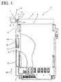
- a card connector as an example for the medium casing adapted to receive a card 4 designed according to the PCMCIA Standard as an example for the mediumhas an ejection mechanism 3 attached along one side of a card-receiving body.
- the ejection mechanism 3includes a two-part elongated ejection rod 6 and 8 comprising a first racked-section 6a and a second racked-section 8a, and an intervening pinion gear 9 engaged with racks 6a and 8a of the first and second ejection rod parts 6 and 8.
- a hook 7is formed on one end of rod part 8 for contacting and ejecting a card 4 at a leading edge thereof.
- a generally rectangular push button device 1includes ejection rod part 6 and a plastic push button 10 which is mounted directly on ejection rod 6 for rotatable movement between an operative and an inoperative position
- Ejection rod 6includes a generally rectangular flat head 11 formed at one end thereof opposite rack 6a.
- Push button 10includes a head-retaining space 12 formed at one end thereof which receives rectangular flat head 11 of ejection rod part 6, thereby connecting ejection rod 6 directly to push button 10.
- Push button 10is molded of plastic and head-retaining space 12 includes a first head-holding section 13 extending in a direction generally parallel to the longitudinal dimension of the push button and a second head-holding section 14 extending generally perpendicular to the first head-holding section 13. As seen in Figures 2 through 6, head-holding sections 13 and 14 intersect each other to form U-shaped spaces or engagement recesses 15 and 16 at their ends.
- the head-retaining space 12further includes a resilient section 17 in the form of an opening and an oblique wall 17a formed adjacent the L-shaped slot.
- push button 10In ejecting card 4 from card connector 2, push button 10 is put in its operative position, i.e. such that the rectangular head is in first head-holding section 13 as shown in broken lines in Figure 1, thereby permitting the first racked-section of ejection rod 6 to be moved rearwardly in the connector body by pushing push button 10.
- push button 10When the card 4 is in use and removal of the card is neither necessary nor wanted, push button 10 is moved to its inoperative position, i.e. such that the rectangular head is in the second head-holding section 14, as shown in Figure 1. In its inoperative position, push button 10 lies close enough to the edge of the card body that there is no fear of push button 10 being inadvertently actuated and unintentionally ejected.
- FIGs 2 through 6show how push button 10 is moved from its inoperative to its operative position.
- flat head 11 of ejection rod 6is positioned in second head-holding section 14 with one end of head 11 located within U-shaped space 16.
- Push button 10is rotated by applying a force in a direction indicated by arrow 18, causing head 11 to move out of U-shaped space 16.
- Thiscauses resilient section 17 to be deformed by head 11 which in turn causes a resilient force to push head 11 towards an edge of L-shaped slot 12 as a counter action (Fig.3).
- Rotation of push button 10continues to put head 11 in parallel with oblique wall 17a, allowing resilient section 17 to return to its original, undeformed state, and providing an audible click and tactile feel (see Fig.4) to allow a user to know the position has been changed. Further continued rotation of push button 10 causes resilient section 17 to deform as head 11 is pushed toward the first head-holding position (see Fig.5).
- push button 10causes head 11 to be move into first head-holding section 13, allowing resilient section 17 to return to its original, undeformed state, and providing another audible click and tactile feedback(see Fig. 6).
- push button 10is in its operative position and is generally in alignment and positive engagement with ejection rod 6 with head 11 positioned in U-shaped space 15 of first head-holding section 13.
- push button 10When it is desired that push button 10 be moved to its inoperative position, as in Figure 2), push button 10 is rotated in reverse, following the sequential positions starting from Figure 6 and going to Figure 2, again feeling and hearing the tactile and audible feedback created by the movement of the head within the head-retaining section.
- Fig.8shows a second embodiment of a molded push button 30 according to the invention.
- Push button 30includes an L-shaped slot defining first and second head-holding sections 33 and 34.
- Curved projection 38 in head- retaining space 32functions to provide a resilient force to head 11 while moving between its operative and inoperative positions.
- Push button 30moves between its two positions in substantially the same way as push button 10.
- curved projection 38is deformed to provide an audible click when head 11 moves toward its operative or inoperative position.
- Push bottons 10 and 30are described as having first and second head-holding sections 13 and 14, and 33 and 34, respectively.
- the second head-holding sectionmay be a head-holding or head-withdrawing section.
- the push buttoncan still provide sensory feedback when moving between its operative and inoperative positions.
- the present inventionis described above as being applied to a card connector which is designed according to the PCMCIA standard. It can be equally applied to a drive devices such as a DVD, MO or MD or other card connectors equipped with eject mechanisms.
Landscapes
- Physics & Mathematics (AREA)
- General Physics & Mathematics (AREA)
- Engineering & Computer Science (AREA)
- Theoretical Computer Science (AREA)
- Details Of Connecting Devices For Male And Female Coupling (AREA)
- Coupling Device And Connection With Printed Circuit (AREA)
Description
Claims (5)
- A medium casing having an eject mechanism forejecting a medium fromthe medium casing, comprising:wherein the head-retaining space (12, 32) includes agenerally L-shaped slot havingan elongated ejection rod (6) mounted along one side ofthe medium casing and having a rectangular flat head(11) formed at one end thereof; anda generally rectangular push button (10, 30) attacheddirectly to the ejection rod for rotatable movement betweenan operative position and an inoperative position andincluding a head-retaining space (12, 32) formed at one endthereof for receiving the rectangular flat head (11) of theejection rod (6),
a first head-holding section (13, 33) extending ina direction generally parallel to the longitudinaldimension of the push button (10, 30) for holding the pushbutton in its operative position, and
a second head-holding section (14, 34) extendinggenerally perpendicular to the first head-holding section forholding the push button in its inoperative position,
whereby, when the head (11) of the ejection rod is inthe first head-holding section (13, 33), the push button (10,30) is in its operative position with the push buttonbeing aligned with the ejection rod and a user can applyforce to the push button to eject the medium from themedium casing. - The medium casing as set forth inclaim 1 wherein the head-retaining space further includes aresilient section (17, 37) adjacent the L-shaped slot adapted to apply a resilient force to the head of the ejection rodduring movement of the push button between its operative andinoperative positions.
- The medium casing as set forth inclaim 2 wherein the resilient section (17) comprises adeformable oblique wall (17a).
- The medium casing as set forth inclaim 1 wherein the first head-holding section and the secondhead-holding section of the push button include U-shapedengagement recesses (15,16) into which a portion of the headof the ejection rod is positioned in the operative andinoperative positions of the push button, respectively.
- A medium casing having an eject mechanism forejecting a medium from the medium casing as set forth in oneof the preceding claims, wherein the medium casing is a cardreceiving connector and the medium is a card.
Applications Claiming Priority (2)
| Application Number | Priority Date | Filing Date | Title |
|---|---|---|---|
| JP37590398 | 1998-12-18 | ||
| JP10375903AJP2000182714A (en) | 1998-12-18 | 1998-12-18 | Injection mechanism and medium mounting device using it |
Publications (2)
| Publication Number | Publication Date |
|---|---|
| EP1014504A1 EP1014504A1 (en) | 2000-06-28 |
| EP1014504B1true EP1014504B1 (en) | 2003-07-30 |
Family
ID=18506249
Family Applications (1)
| Application Number | Title | Priority Date | Filing Date |
|---|---|---|---|
| EP99125387AExpired - LifetimeEP1014504B1 (en) | 1998-12-18 | 1999-12-20 | Eject mechanism with rotatable push button |
Country Status (8)
| Country | Link |
|---|---|
| US (1) | US6139340A (en) |
| EP (1) | EP1014504B1 (en) |
| JP (1) | JP2000182714A (en) |
| CN (1) | CN1109380C (en) |
| DE (1) | DE69909953T2 (en) |
| MY (1) | MY133215A (en) |
| SG (1) | SG75191A1 (en) |
| TW (1) | TW433601U (en) |
Families Citing this family (19)
| Publication number | Priority date | Publication date | Assignee | Title |
|---|---|---|---|---|
| JP3338415B2 (en) | 1999-12-28 | 2002-10-28 | 山一電機株式会社 | Card connector |
| JP3429267B2 (en)* | 2000-04-12 | 2003-07-22 | 山一電機株式会社 | Card connector |
| JP3530460B2 (en) | 2000-04-27 | 2004-05-24 | 山一電機株式会社 | Card connector |
| TW481377U (en)* | 2000-06-14 | 2002-03-21 | Fci Taiwan Ltd | Smart card connector, ejecting mechanism for same, and compound connector device |
| JP3471736B2 (en) | 2000-10-19 | 2003-12-02 | 山一電機株式会社 | Card connector |
| JP3429266B2 (en) | 2000-10-19 | 2003-07-22 | 山一電機株式会社 | Card connector |
| JP3436530B2 (en) | 2001-02-08 | 2003-08-11 | 山一電機株式会社 | Card connector |
| TW474489U (en)* | 2001-02-27 | 2002-01-21 | Hon Hai Prec Ind Co Ltd | Card ejecting mechanism of electrical card connector |
| JP3431608B2 (en) | 2001-03-06 | 2003-07-28 | 山一電機株式会社 | Card connector |
| JP3443103B2 (en)* | 2001-03-23 | 2003-09-02 | 山一電機株式会社 | Card connector |
| JP3443102B2 (en) | 2001-03-23 | 2003-09-02 | 山一電機株式会社 | Card connector |
| TW561418B (en)* | 2001-12-26 | 2003-11-11 | Hon Hai Prec Ind Co Ltd | Electric card connector and the assembly method |
| TW537524U (en)* | 2002-02-08 | 2003-06-11 | Molex Inc | Push button device of card ejecting mechanism for an electronic card |
| JP2004055256A (en)* | 2002-07-18 | 2004-02-19 | Tyco Electronics Amp Kk | Connector for cards |
| EP1445728A1 (en)* | 2003-02-04 | 2004-08-11 | Molex Incorporated | Ic card connector |
| JP5163453B2 (en)* | 2008-11-28 | 2013-03-13 | 富士通株式会社 | Button device and electronic device |
| US8177564B1 (en) | 2010-12-03 | 2012-05-15 | Yamaichi Electronics Co., Ltd. | Receptacle connector and an electrical connector using the same |
| US8636136B2 (en) | 2011-12-20 | 2014-01-28 | Kimberly-Clark Worldwide, Inc. | Apparatus and method for rotatably conveying and applying discrete parts to a substrate |
| CN116852310A (en)* | 2023-04-17 | 2023-10-10 | 合肥联宝信息技术有限公司 | Automatic assembly structure and system |
Family Cites Families (10)
| Publication number | Priority date | Publication date | Assignee | Title |
|---|---|---|---|---|
| US5026296A (en)* | 1990-03-05 | 1991-06-25 | Japan Aviation Electronics Industry, Limited | Electrical connector equipped with release mechanism |
| JPH03297084A (en)* | 1990-04-17 | 1991-12-27 | I T T Canon:Kk | Card connector with ejector |
| JP2603509Y2 (en)* | 1992-12-28 | 2000-03-15 | 日本エー・エム・ピー株式会社 | Card edge connector |
| JP2847032B2 (en)* | 1994-04-22 | 1999-01-13 | ヒロセ電機株式会社 | Electric connector for IC card |
| JP3117360B2 (en)* | 1994-04-28 | 2000-12-11 | タイコエレクトロニクスアンプ株式会社 | Card edge connector with eject mechanism |
| US5443395A (en)* | 1994-06-08 | 1995-08-22 | Molex Incorporated | Ejector system for an IC card connector apparatus |
| JP2707061B2 (en)* | 1994-10-06 | 1998-01-28 | モレックス インコーポレーテッド | Card eject mechanism in card drive unit |
| US5492480A (en)* | 1994-10-31 | 1996-02-20 | Fusselman; David L. | Memory card connector having improved resilient eject mechanism and method of use |
| JP3297614B2 (en)* | 1996-11-12 | 2002-07-02 | ヒロセ電機株式会社 | Card eject button device for PC card connector |
| TW377900U (en)* | 1998-06-25 | 1999-12-21 | Hon Hai Prec Ind Co Ltd | Foldable button apparatus for electric connector |
- 1998
- 1998-12-18JPJP10375903Apatent/JP2000182714A/enactivePending
- 1999
- 1999-12-17CNCN99127892.5Apatent/CN1109380C/ennot_activeExpired - Fee Related
- 1999-12-17SGSG1999006417Apatent/SG75191A1/enunknown
- 1999-12-17MYMYPI99005560Apatent/MY133215A/enunknown
- 1999-12-20USUS09/468,272patent/US6139340A/ennot_activeExpired - Fee Related
- 1999-12-20DEDE69909953Tpatent/DE69909953T2/ennot_activeExpired - Fee Related
- 1999-12-20EPEP99125387Apatent/EP1014504B1/ennot_activeExpired - Lifetime
- 2000
- 2000-01-04TWTW088221618Upatent/TW433601U/ennot_activeIP Right Cessation
Also Published As
| Publication number | Publication date |
|---|---|
| EP1014504A1 (en) | 2000-06-28 |
| JP2000182714A (en) | 2000-06-30 |
| US6139340A (en) | 2000-10-31 |
| CN1259784A (en) | 2000-07-12 |
| DE69909953T2 (en) | 2004-05-27 |
| CN1109380C (en) | 2003-05-21 |
| MY133215A (en) | 2007-10-31 |
| SG75191A1 (en) | 2000-09-19 |
| DE69909953D1 (en) | 2003-09-04 |
| TW433601U (en) | 2001-05-01 |
Similar Documents
| Publication | Publication Date | Title |
|---|---|---|
| EP1014504B1 (en) | Eject mechanism with rotatable push button | |
| CN100583567C (en) | Card connector for integrated connection of ejection part and cam follower and locking part | |
| US5033972A (en) | Electrical connector | |
| EP0686936B1 (en) | Ejector system for an IC card connector apparatus | |
| JP2887865B2 (en) | Connector device | |
| US6473076B1 (en) | Apparatus and method for controlling the power of a handheld computing device using a stylus | |
| US5967811A (en) | Memory card connector | |
| KR100309044B1 (en) | IC card connector | |
| JP3320365B2 (en) | Electrical connector for card | |
| US6152748A (en) | Card ejection device and a card connector using the same | |
| EP0895180B1 (en) | IC card connector | |
| CN100511863C (en) | Connector with reduced size | |
| KR100309043B1 (en) | IC card connector | |
| US6074227A (en) | Ejecting mechanism and a connector using the same | |
| JP2002124343A (en) | Connector for memory card | |
| US6089890A (en) | Card release device | |
| JPH07168919A (en) | Connector device | |
| US6702599B2 (en) | Card ejecting mechanism for an electronic card connector | |
| US5597990A (en) | Electrical switch | |
| KR100309042B1 (en) | Connector device for ic card | |
| US6059587A (en) | Card connector | |
| WO2005093910A1 (en) | Slider unit and card connector | |
| JP2004095277A (en) | Card connector and eject mechanism | |
| EP0328130A1 (en) | A safety-belt device | |
| US5852546A (en) | Computer with an improved disk drive eject button actuation assembly |
Legal Events
| Date | Code | Title | Description |
|---|---|---|---|
| PUAI | Public reference made under article 153(3) epc to a published international application that has entered the european phase | Free format text:ORIGINAL CODE: 0009012 | |
| AK | Designated contracting states | Kind code of ref document:A1 Designated state(s):DE FR GB IE IT | |
| AX | Request for extension of the european patent | Free format text:AL;LT;LV;MK;RO;SI | |
| 17P | Request for examination filed | Effective date:20001220 | |
| AKX | Designation fees paid | Free format text:DE FR GB IE IT | |
| 17Q | First examination report despatched | Effective date:20010202 | |
| GRAH | Despatch of communication of intention to grant a patent | Free format text:ORIGINAL CODE: EPIDOS IGRA | |
| GRAH | Despatch of communication of intention to grant a patent | Free format text:ORIGINAL CODE: EPIDOS IGRA | |
| GRAA | (expected) grant | Free format text:ORIGINAL CODE: 0009210 | |
| AK | Designated contracting states | Designated state(s):DE FR GB IE IT | |
| REG | Reference to a national code | Ref country code:GB Ref legal event code:FG4D | |
| REG | Reference to a national code | Ref country code:IE Ref legal event code:FG4D | |
| REF | Corresponds to: | Ref document number:69909953 Country of ref document:DE Date of ref document:20030904 Kind code of ref document:P | |
| ET | Fr: translation filed | ||
| PLBE | No opposition filed within time limit | Free format text:ORIGINAL CODE: 0009261 | |
| STAA | Information on the status of an ep patent application or granted ep patent | Free format text:STATUS: NO OPPOSITION FILED WITHIN TIME LIMIT | |
| 26N | No opposition filed | Effective date:20040504 | |
| PGFP | Annual fee paid to national office [announced via postgrant information from national office to epo] | Ref country code:IE Payment date:20041022 Year of fee payment:6 | |
| PGFP | Annual fee paid to national office [announced via postgrant information from national office to epo] | Ref country code:GB Payment date:20041104 Year of fee payment:6 | |
| PGFP | Annual fee paid to national office [announced via postgrant information from national office to epo] | Ref country code:FR Payment date:20041201 Year of fee payment:6 | |
| PGFP | Annual fee paid to national office [announced via postgrant information from national office to epo] | Ref country code:DE Payment date:20041230 Year of fee payment:6 | |
| PG25 | Lapsed in a contracting state [announced via postgrant information from national office to epo] | Ref country code:IT Free format text:LAPSE BECAUSE OF NON-PAYMENT OF DUE FEES Effective date:20051220 Ref country code:GB Free format text:LAPSE BECAUSE OF NON-PAYMENT OF DUE FEES Effective date:20051220 | |
| PG25 | Lapsed in a contracting state [announced via postgrant information from national office to epo] | Ref country code:DE Free format text:LAPSE BECAUSE OF NON-PAYMENT OF DUE FEES Effective date:20060701 | |
| GBPC | Gb: european patent ceased through non-payment of renewal fee | Effective date:20051220 | |
| PG25 | Lapsed in a contracting state [announced via postgrant information from national office to epo] | Ref country code:FR Free format text:LAPSE BECAUSE OF NON-PAYMENT OF DUE FEES Effective date:20060831 | |
| REG | Reference to a national code | Ref country code:IE Ref legal event code:MM4A | |
| REG | Reference to a national code | Ref country code:FR Ref legal event code:ST Effective date:20060831 |