EP1012715B1 - Hardware assisted method of context switching - Google Patents
Hardware assisted method of context switchingDownload PDFInfo
- Publication number
- EP1012715B1 EP1012715B1EP98945916AEP98945916AEP1012715B1EP 1012715 B1EP1012715 B1EP 1012715B1EP 98945916 AEP98945916 AEP 98945916AEP 98945916 AEP98945916 AEP 98945916AEP 1012715 B1EP1012715 B1EP 1012715B1
- Authority
- EP
- European Patent Office
- Prior art keywords
- context
- csa2
- save area
- register
- storing
- Prior art date
- Legal status (The legal status is an assumption and is not a legal conclusion. Google has not performed a legal analysis and makes no representation as to the accuracy of the status listed.)
- Expired - Lifetime
Links
Images

Classifications
- G—PHYSICS
- G06—COMPUTING OR CALCULATING; COUNTING
- G06F—ELECTRIC DIGITAL DATA PROCESSING
- G06F9/00—Arrangements for program control, e.g. control units
- G06F9/06—Arrangements for program control, e.g. control units using stored programs, i.e. using an internal store of processing equipment to receive or retain programs
- G06F9/30—Arrangements for executing machine instructions, e.g. instruction decode
- G06F9/30098—Register arrangements
- G06F9/3012—Organisation of register space, e.g. banked or distributed register file
- G06F9/30123—Organisation of register space, e.g. banked or distributed register file according to context, e.g. thread buffers
- G—PHYSICS
- G06—COMPUTING OR CALCULATING; COUNTING
- G06F—ELECTRIC DIGITAL DATA PROCESSING
- G06F9/00—Arrangements for program control, e.g. control units
- G06F9/06—Arrangements for program control, e.g. control units using stored programs, i.e. using an internal store of processing equipment to receive or retain programs
- G06F9/30—Arrangements for executing machine instructions, e.g. instruction decode
- G06F9/30003—Arrangements for executing specific machine instructions
- G06F9/3004—Arrangements for executing specific machine instructions to perform operations on memory
- G06F9/30043—LOAD or STORE instructions; Clear instruction
- G—PHYSICS
- G06—COMPUTING OR CALCULATING; COUNTING
- G06F—ELECTRIC DIGITAL DATA PROCESSING
- G06F9/00—Arrangements for program control, e.g. control units
- G06F9/06—Arrangements for program control, e.g. control units using stored programs, i.e. using an internal store of processing equipment to receive or retain programs
- G06F9/30—Arrangements for executing machine instructions, e.g. instruction decode
- G06F9/30003—Arrangements for executing specific machine instructions
- G06F9/3005—Arrangements for executing specific machine instructions to perform operations for flow control
- G06F9/30054—Unconditional branch instructions
- G—PHYSICS
- G06—COMPUTING OR CALCULATING; COUNTING
- G06F—ELECTRIC DIGITAL DATA PROCESSING
- G06F9/00—Arrangements for program control, e.g. control units
- G06F9/06—Arrangements for program control, e.g. control units using stored programs, i.e. using an internal store of processing equipment to receive or retain programs
- G06F9/46—Multiprogramming arrangements
- G06F9/461—Saving or restoring of program or task context
- G06F9/462—Saving or restoring of program or task context with multiple register sets
Definitions
- the present inventionrelates to a data processing unit with hardware assisted context switching capabilities.
- Most embedded and real time control systemsare designed according to a model in which interrupt handlers and software managed tasks are each considered to be executing on their own virtual microcontroller. That model is generally supported by the services of a real time executive or operating system, layered on top of the features and capabilities of the underlying machine architecture.
- a virtual microcontrollercan be seen as a task having its own general purpose registers and associated special function registers like program counter, program status word, etc., which represent the task's context. Handling of these virtual microcontrollers in most of the known systems is done by means of software which saves and restores the respective context. Therefore, software for such a data processing unit needs an increased amount of memory and execution overhead for the context switching operation reduces the processing bandwidth available to application tasks.
- US-AA 074 353discloses a plurality of trap save areas are linked to form a pool from which an area may be loaded with context from various sources in response to a trap condition, such as the addressing of unusable memory.
- the loaded areais unlinked from the pool and various pointers changed to reflect such unlinking.
- the unlinked areais associated with the process which was executing at the time of the occurrence of the trap condition by effectively being coupled to the interrupt level of such process.
- a trap handler routine specific to the nature of the trap conditionis executed following which the unlinked area is returned to the pool and the various pointers changed to reflect such return.
- US-A-4 025 904discloses context switching in which the memory address of a workspace of a problem program is stored in the memory workspace of an interrupt program.
- the memory workspacestores a problem program workspace pointer, program counter contents and contents of a status register upon occurrence of an interrupt.
- the location of the workspaceis referenced by the contents of a workspace pointer register.
- the contents of the registerare stored in one element of a new workspace by loading new contents into the workspace pointer register.
- This objectis achieved by using a linked list mechanism to link save areas in a memory wherein each save area stores at least part of a context of a respective task.
- a method of context switching from a first task to a second task in a data processing unitcomprising:- a memory comprising at least one previous context save area and at least one unused context save area, each context save area having a first portion for storing the context and a second portion for storing a link word; a register file having a plurality of general purpose registers and a context switch register for storing the address of the previous context save area; an instruction control unit having a program counter register, a program status word register and a context switch control unit; and means for coupling the memory with the register file and the instruction control unit, and for coupling the instruction control unit with the register file; the method comprising the steps of: a) performing the context switch from the first task to the second task upon an instruction or an exception, the context comprising the content of a predefined number of general purpose registers, the content of the program counter register and the content of the program status word register; b) acquiring a new save area from the unused
- a data processing unitcomprises a register file with a plurality of general purpose registers and special purpose registers that enable the hardware to manage context switch operations.
- the data processing unitcomprises a memory having an actual context save area and an unused context save area coupled with the register file.
- an instruction control unit with a program counter register and a program status registeris coupled with the memory and the register file.
- Each context save areaincludes a word containing information that serves to link that save area to the next save area in a chain of linked save areas.
- Free save areas(those not currently holding context information for a "live" task or function) are linked together in one chain. Saved contexts resulting from a sequence of calls traps, or interrupts are linked together in another chain, termed the previous context list.
- the current contextresides in the general purpose and program state registers of the processor. To save the current context and create a new one, the following steps can be performed by the processor hardware:
- the processor contextis partitioned into two parts, the upper context, and the lower context.
- the two partscan be saved and restored separately.
- the initial context save operationthat is performed on a function call, interrupt, or trap saves only the upper context.
- a function that issues a callexpects its upper context to be preserved across the cail, but does not expect its lower context to be preserved.
- the called functiontherefore never needs to incur the cost of saving the lower context.
- a trap or interrupt handler that does not modify any of the register values in the lower contextcan also avoid the cost of saving the lower context.
- the data processing unitprovides the ability to create a real time executive or operating system which can be very "thin". Much of the work of switching between one task and another is handled efficiently by the hardware itself.
- taskis used in a general sense to refer to an independent thread of control, having its own context that defines the state of the virtual processor on which it executes.
- SMTsoftware managed tasks
- ISRinterrupt service routines
- Software managed tasksare created through services of a real time kernel or operating system, and dispatched under control of scheduling software.
- Interrupt service routinesare dispatched by the hardware, in response to an interrupt.
- an ISRIn some systems, the main function of an ISR is simply to queue a software managed task and jump to the task scheduler. In those systems, it is actually a software managed task that, from a functional point of view, is responding to the interrupt event. Software managed tasks are sometimes referred to elsewhere as user tasks. That reflects an assumption that they will execute in user mode, whereas ISR are expected to execute in supervisor mode. In embedded systems, however, SMTs often run in supervisor mode, for efficient access to system resources.
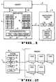
- Fig. 1shows a block diagram of relevant parts for task switching in a data processing unit.
- a memory 1is coupled with a register file 2 through D buses 4a and 4b.
- the register file 2contains a first group of data registers 2a and a second group of address registers 2b which constitute the general purpose registers.
- a second set of registers 2cform the system registers wherein Fig. 1 shows only three of these registers which are necessary for context switching.
- the three registersare the FCX register 2d, the PCXI, the PCX-register 2e, and the FCXLMT-register 2f.
- the system registerscan be part of the register file or be located elsewhere in the core of a microprocessor.
- Fig. 1shows a block diagram of relevant parts for task switching in a data processing unit.
- a memory 1is coupled with a register file 2 through D buses 4a and 4b.
- the register file 2contains a first group of data registers 2a and a second group of address registers 2b
- instruction control unit 3which is connected via bus 5 to the memory 1 and via bus 6 to the register file 2.
- the instruction control unitis responsible for executing instructions stored in a program sequence in memory 1. Therefore, instruction control unit comprises a program counter register 3a and a program status word register 3b.
- instruction control unit 3comprises a contact switch control unit 3c.
- the context switch control unit 3cis responsible for saving the contents of all necessary registers associated to a task which build the context of a task.
- a data processing unit according to the inventionsaves the context of a task automatically without any additional instructions provided by respective software program.
- the context switch control unit 3cis part of the instruction control unit 3, the respective instructions or events are checked by the context control unit 3c.
- the context switch control unit 3cIn case of a call instruction, an exception such as an external interrupt or a trap, or a system call instruction, the context switch control unit 3c automatically stores the context into a memory field, the so-called context save areas.
- the management of a plurality of context save areasis handled by the specific task switching registers 2d, 2e and 2f provided in the system register file 2.
- the contextis everything the processor needs in order to define the state of the associated task and enable its continued execution. It includes the central processing unit general registers that the task uses, the task current program counter, and its program status word. Technically, the context also includes the contents of task memory space and various special function registers that can effect its execution, for example, the memory protection registers, etc. In this embodiment, however, the term will be used in a more restricted sense to refer only to the state that must be immediately saved when a task is interrupted or suspended, and restored before its execution is resumed. Task memory space does not usually need to be saved because it is typically left untouched while the task is suspended, and not reassigned to another task.
- the processorsuspends the execution of the current task by saving its context in memory before starting execution of the interrupt handler. Later, the saved context can be reloaded to resume execution of the interrupted task.
- the calling routineWhen a function call is made, the calling routine also has context that must be saved and then restored in order to resume the caller's execution after return from the function.
- the principal differenceis that interrupts occur asynchronously, so that the context saved must include all registers that the interrupted task might be using, while calls are synchronous.
- the calling functionknows when it is about to make a call, so calling and called functions can cooperate to minimize the amount of context that must be saved and restored. This is done by petitioning the general registers into subsets: those whose contents will be preserved across the call, namely non-volatile registers, and those whose contents will not be preserved, namely scratch registers.
- the calleris responsible for preserving any of its context that resides in scratch registers before the call, while the called function is responsible for preserving the callers values in any non-volatile registers that the called function uses.
- the calling functionpreserves its scratch register context, when necessary, either by saving the registers in memory, or copying them to non-volatile registers.
- the compiler register allocatortries to minimize the need for either action by tracking what data items are live across a call, defined before the call and used after it, and allocating those items to non-volatile registers.
- the compilertries to minimize the amount of context saving and restoring in the called function by minimizing the number of non-volatile registers that it uses.
- Bus 4a and bus 4beach are as wide as for example at least two or more registers. Therefore, as shown in Fig. 1, for example four registers, an even and an odd data register and an even and an odd address register can be accessed in parallel. This is done by grouping data registers and address registers each into a group of odd and even registers.
- the main featureis that the saving of the non-volatile registers is integrated with the call-instruction so it happens in parallel with the call jump.
- the restoring of the registersis integrated with the return instruction and happens in parallel with the return jump.
- the called functionneed not concern itself with saving and restoring the callers context, and it is freed of any need to minimize the number of non-volatile registers that it uses.
- each contextis divided into two portions of context which are referred to as the upper context and the lower context
- Upper and lower contextcan have preferably the same size, but if necessary can also have different sizes.
- the linked list mechanismprovides the convenience that every context save area can have a different size if necessary.
- the content of the upper contextis shown in Fig. 5 by numeral 8
- the content of the lower contextis shown in Fig. 5 by numeral 9.
- the upper context 8consists of the upper address registers A10-A15 and the upper data registers D8-D15. These are the registers that are designated as non-volatile, for purposes of function calling.
- the upper contextalso includes the processor status word PSW.
- the lower context 9consists of the lower address registers A2-A7 and the lower data registers D0-D7, plus the interrupt program counter value. Both upper and lower context 8, 9 include a link word. In the upper context, however, the link is embedded in PCXI.
- Registers A0-A1 in the lower address registers and A8-A9 in the upper address registersare defined as system global registers. They are not included in either context partition, and are not saved and restored across calls or interrupts. They are normally used by the operating system to reduce system overhead, and can be optionally write protected against unintended modification by application tasks. If a call or an interrupt is executed, only the upper context is automatically stored in memory 1.
- the lower contextcan be stored by a special instruction causing the allocation of respective memory and storing the contents of the lower context as will be explained in more detail below.
- the respective handlercan execute immediately and return, leaving the unsaved portions of the interrupted task context untouched.
- interrupt handlers that make callsonly one additional instruction is needed to save the registers that were not saved as part of the interrupt sequence.
- the associated registers of the lower contextcan be used to pass arguments to a called function. Likewise, since they are not automatically restored as part of a return-sequence, they can be used to pass return values from called functions back to their callers.
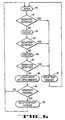
- Fig. 6shows a sequential execution model in order to understand the exception and interrupt handling of a data processing unit according to the present invention.
- the fundamental execution modelis a fundamental execution model of a sequential flow of execution. Each instruction is individually fetched in step 60, decoded in step 62, and executed in step 64. If an instruction causes an exception, this is checked in steps 61, 63 and 65. Then, none of the side effects or updates from a following instruction are seen in the machine. This is very important since it significantly simplifies the exception handling model.
- step 66the state of the program counter, general purpose registers and the memory are updated and in step 68, it is checked whether an interrupt is pending. Steps 67 and 69 set the respective trap or interrupt handlers.
- a data processing unitemploys linked lists of fixed size context save areas (CSAs).
- Fig. 2shows how these CSAs are organized in memory 1.
- the contents of PCX-register 2epoints at an address where a context save area CSA2 begins.
- a context save areacan have two portions whereby the first portion contains the actual context and a second portion 1b includes a pointer to another context save area, context save area CSA1 in Fig. 2.
- the FCX-register 2dpoints to the first of a list of unused context save areas CSA3, CSA4, and CSA5.
- Each context save area CSA3, CSA4, and CSA5comprises a link word 1c, 1d and 1e which contains the address of the following CSA.
- FCX registercontains the starting address of CSA3
- linking word 1ccontains the address of CSA4
- linking word 1dcontains the starting address of CSA5.
- the system register filecontains also a comparator 2g which compares the contents of FCX-register 2d and FCXLMT-register 2f. If the contents of both register 2d and 2f are equal, a signal is sent to terminal 7.
- a CSAis, for example, 16 words of on-chip memory storage, aligned on a 16-word boundary.
- a single CSAcan hold exactly one upper or one lower context 8, 9 as shown in Fig. 5.
- the starting word of each upper and lower context save areas 8, 9start with the link word or PCXI.
- unused context save areas, CSA3, CSA4, CSA5are linked together on a free list.
- Context switch register 2dpoints at the first context save areas CSA3 of the linked list They are allocated from the free list as needed, and returned to it when no longer needed. The allocation and freeing are done by the processor hardware and are transparent to applications code. Only the system start-up code and certain operating systems exception handling routines ever need to access the CSA lists on memory storage explicitly.
- Context switch register 2ealways points to the actual context switch area, which is in the case of Fig. 2 context save area CSA2.
- FCX-register 2dalways points to an available CSA, where the upper context can be automatically saved in the event of a call or interrupt, or the lower context can be saved in the event of a special instruction.
- the link wordis read from it, supplying a new value for FCX.
- context switchingis therefore a read-modify write operation.
- the new value of FCXis immediately available for subsequent calls or interrupts or for explicit saving of the lower context.
- FCXLMT-register 2fis used to recognize impending CSA list underflow. If the value of FCX is used on an interrupt or call matches the limit value, the context safe operation completes but comparator 2g generates the trap signal that forces the target address to the trap vector address for CSA list depletion. The action taken by the trap handler depends on system design; it might issue a system reset, if it is determined that the CSA list depletion resulted from an unrecoverable software error.
- the PCX field in the PCXI.PCX-registerpoints to the CSA for the previous context, for example, the context that will be restored when a respective return instruction is executed. It is the list head pointer for a linked list of saved contexts.
- the saved contextit points to could be an upper context or a lower context, depending on whether the preceding context save operation was for a call, interrupt or trap, or for the save context-instruction operation.
- the free context listcontains three free CSAs, namely CSA3, CSA4, and CSA5
- the previous context listcontains two CSAs, namely CSA2 and CSA 1, as shown in Fig. 2.
- the context save operationis performed, the first context save area in the free context list CSA3 is pulled off and placed on the front of the previous context list.
- This movement from the free to the previous context listinvolves the updating of the PCX-register 2e and the FCX-regist 2d and the link word of the context save areas being transferred in the following way, as shown in Fig. 3.
- An additional help registermight be used if necessary to complete this procedure.
- the help registerwill be loaded with the content of the link word 1c of CSA3, the link word of CSA3 1c is loaded with the content of PCX register 2e; the PCX-register 2e is loaded with the content of FCX-register 2d; and the FCX-register is loaded with the content of the help register.
- the context and context switch registersnow look like the diagram shown in Fig. 4.
- the processor context to be savedcan now be written into the rest of the CSA3 which has been transferred to the front of the previous context list.
- the processor context to be restoredis read from the CSA at the front of the previous context list, in this case from CSA3.
- the CSAis now transferred from the previous context list to the front of the free context list
- This movement from the previous to the free context listinvolves the updating of the PCX-register 2e and the FCX-register 2d and the link word of the context save area being transferred in the following way.
- the help registeris loaded with the link word 1c of CSA3; the link word 1c of CSA3 is loaded with the content of FCX-register 2d; FCX-register 2d is loaded with the content of PCX-register 2e; and PCX-register 2e is loaded with the content of the help register.
- the context and the context switch registersnow look like the diagram shown Fig. 2.
- a data processing unitcan initiate the same procedure for saving an upper or lower context by a special instruction.
- a save lower context instructioncan initiate the same procedure as a call-instruction or an exception.
- a so-called store context-instructioncan store either the lower or upper context without changing the list of used context save areas or unused context save areas.
- a restore lower contexteffects the same as a return-instruction whereas a load context-instruction loads either the lower or upper context from the actual context save area without changing the list of used and unused context save area.
Landscapes
- Engineering & Computer Science (AREA)
- Software Systems (AREA)
- Theoretical Computer Science (AREA)
- Physics & Mathematics (AREA)
- General Engineering & Computer Science (AREA)
- General Physics & Mathematics (AREA)
- Executing Machine-Instructions (AREA)
Description
- a context save area is taken from the free list,
- the current context is stored into the save area,
- the save area is added to the head of the previous context list.
- the save area at the head of the previous context list isremoved from that list,
- the current context is loaded from the save area just removedfrom the previous context list,
- the save area is added to the free context save area list
- a system call instruction is issued, requesting a task switch,
- the system call trap causes the current context to be saved,as described previously,
- the trap handler for the system call trap changes the value ofthe processor register that points to the head of the previous contextlist, causing it to point to the save area for the task to which executionis being switched,
- the trap handler exits, causing the context for the new task tobe loaded and execution of that task to resume.
In addition to the automatic save and restore function executed by the context
Claims (10)
- A method of context switching from a first task to a second task in adata processing unit comprising:-characterised in that step c) comprises storing the content of aplurality of registers (2a, 2b, 8, 9) in parallel in the context save area (CSA2).a memory (1) comprising at least one previous context save area(CSA3, 1c, CSA4, 1d, CSA5, 1e) and at least one unused context save area(CSA2, 1b, CSA1, 1a), each context save area (CSA1, 1a, CSA2, 1b, CSA3,1c, CSA4, 1d, CSA5, 1e) having a first portion (CSA1, CSA2, CSA3, CSA4,CSA5) for storing the context and a second portion (1a, 1b, 1c, 1d, 1e) forstoring a link word;a register file (2) having a plurality of general purpose registers (2a,2b) and a context switch register (2c, 2d, 2e, 2f, 2g) for storing the address ofthe previous context save area (CSA3, 1c);an instruction control unit (3) having a program counter register (3a),a program status word register (3b) and a context switch control unit (3c);andmeans (4a, 4b, 5,6) for coupling the memory (1) with the register file(2) and the instruction control unit (3), and for coupling the instructioncontrol unit (3) with the register file (2);the method comprising the steps of:a) performing the context switch from the first task to the secondtask upon an instruction or an exception, the context comprising the contentof a predefined number of general purpose registers (2a, 2b), the content ofthe program counter register (3a) and the content of the program status wordregister (3b);b) acquiring a new save area (CSA2, 1b) from the unused save area(CSA2, 1b, CSA1, 1a);c) storing the context of the first task in the first portion (CSA2) ofthe new save area (CSA2, 1b);d) storing the content of the context switch register (2c, 2d, 2e, 2f,2g) in the second portion (1b) of the unused context save area (CSA2, 1b) tolink actual context save areas (CSA3, CSA4, CSA5) and unused context saveareas (CSA2, CSA1) as respective first and second context save areas;e) storing the address of the unused context save area (CSA1, 1a) inthe context switch register (2c, 2d, 2e, 2f, 2g); andf) linking the new save area (CSA2, 1b) with a previous contextsave area (CSA3, 1c);
- A method according to claim 1, further comprising, for switchingback to the first task, the steps of storing the content of the second portion(1b) of the second context save area (CSA2, 1b) in the context switch register(2c, 2d, 2e, 2f, 2g), and restoring the context stored in the first portion(CSA2) of the first context save area (CSA2, 1b).
- A method according to claim 1, wherein step b) comprises assigning anew context save area (CSA2, 1b) from the list of unused context areas bystoring the content of the second portion (1b) of the first unused context savearea (CSA2, 1b) of the linked list in a first context switch register (2e),storing the content of a second context switch register (2d) in the first contextswitch register (2e), storing the content of the first context switch register(2e) in the second portion (1b) of the new assigned context save area (CSA2,1b), and storing the context in the first portion (CSA2) of the new assignedcontext save area (CSA2, 1b).
- A method according to claim 3, further comprising, for switchingback to the first task, the steps of storing the content of the second portion(1b) of the actual context save area (CSA2, 1b) in the first context switchregister (2e), storing the content of the first context switch register (2e) in thesecond context switch register (2d), storing the content of the second contextswitch register (2d) in the second portion (1c) of the actual context save area(CSA3, 1c), and restoring the context stored in the first portion (CSA2) of thecontext save area (CSA2, 1b) which is indicated by the first context switchregister (2e).
- A method according to claim 4, further comprising a third contextswitch register (2f) for storing the address of a definable unused context savearea in the linked list, and a comparator (2g) coupled with the second andthird context switch registers (2d, 2f) which generates an exception if thecontents of both registers are equal.
- A method according to claim 1, wherein each context is divided intoat least an upper and a lower context (8, 9), the upper context (8) being storedby the context control switch control unit (3c) and the lower context beingstorable by an instruction triggering an additional task switch.
- A method according to claim 6, wherein the upper and lower contexts(8, 9) have the same size.
- A method according to claim 1, wherein the general purpose registers(2a, 2b) in the register file (2) are organized in a plurality of groups which areaccessible in parallel.
- A method according to claim 8, wherein said plurality of groupscomprises a first group of address registers (2b) and a second group of dataregisters (2a).
- A method according to claim 9, wherein said first and second groups(2a, 2b) are each divided into groups of odd and even registers which areaccessible in parallel.
Applications Claiming Priority (3)
| Application Number | Priority Date | Filing Date | Title |
|---|---|---|---|
| US928252 | 1992-08-10 | ||
| US08/928,252US6128641A (en) | 1997-09-12 | 1997-09-12 | Data processing unit with hardware assisted context switching capability |
| PCT/US1998/018592WO1999014671A1 (en) | 1997-09-12 | 1998-09-04 | Data processing unit with hardware assisted context switching capability |
Publications (2)
| Publication Number | Publication Date |
|---|---|
| EP1012715A1 EP1012715A1 (en) | 2000-06-28 |
| EP1012715B1true EP1012715B1 (en) | 2001-11-21 |
Family
ID=25455966
Family Applications (1)
| Application Number | Title | Priority Date | Filing Date |
|---|---|---|---|
| EP98945916AExpired - LifetimeEP1012715B1 (en) | 1997-09-12 | 1998-09-04 | Hardware assisted method of context switching |
Country Status (7)
| Country | Link |
|---|---|
| US (1) | US6128641A (en) |
| EP (1) | EP1012715B1 (en) |
| JP (1) | JP2001516922A (en) |
| KR (1) | KR20010030592A (en) |
| DE (1) | DE69803304T2 (en) |
| IL (1) | IL134236A0 (en) |
| WO (1) | WO1999014671A1 (en) |
Cited By (1)
| Publication number | Priority date | Publication date | Assignee | Title |
|---|---|---|---|---|
| WO2005050435A3 (en)* | 2003-11-12 | 2006-04-27 | Infineon Technologies Ag | Interrupt and trap handling in an embedded multi-threaded processor to avoid priority inversion and maintain real-time operation |
Families Citing this family (55)
| Publication number | Priority date | Publication date | Assignee | Title |
|---|---|---|---|---|
| US6128728A (en) | 1997-08-01 | 2000-10-03 | Micron Technology, Inc. | Virtual shadow registers and virtual register windows |
| US7941647B2 (en) | 1999-01-28 | 2011-05-10 | Ati Technologies Ulc | Computer for executing two instruction sets and adds a macroinstruction end marker for performing iterations after loop termination |
| US7275246B1 (en)* | 1999-01-28 | 2007-09-25 | Ati International Srl | Executing programs for a first computer architecture on a computer of a second architecture |
| US8074055B1 (en) | 1999-01-28 | 2011-12-06 | Ati Technologies Ulc | Altering data storage conventions of a processor when execution flows from first architecture code to second architecture code |
| US8121828B2 (en) | 1999-01-28 | 2012-02-21 | Ati Technologies Ulc | Detecting conditions for transfer of execution from one computer instruction stream to another and executing transfer on satisfaction of the conditions |
| US8127121B2 (en) | 1999-01-28 | 2012-02-28 | Ati Technologies Ulc | Apparatus for executing programs for a first computer architechture on a computer of a second architechture |
| US6598118B1 (en) | 1999-07-30 | 2003-07-22 | International Business Machines Corporation | Data processing system with HSA (hashed storage architecture) |
| US6470442B1 (en) | 1999-07-30 | 2002-10-22 | International Business Machines Corporation | Processor assigning data to hardware partition based on selectable hash of data address |
| US6449691B1 (en) | 1999-07-30 | 2002-09-10 | International Business Machines Corporation | Asymmetrical cache properties within a hashed storage subsystem |
| US6516404B1 (en)* | 1999-07-30 | 2003-02-04 | International Business Machines Corporation | Data processing system having hashed architected processor facilities |
| US6658556B1 (en) | 1999-07-30 | 2003-12-02 | International Business Machines Corporation | Hashing a target address for a memory access instruction in order to determine prior to execution which particular load/store unit processes the instruction |
| US6446165B1 (en) | 1999-07-30 | 2002-09-03 | International Business Machines Corporation | Address dependent caching behavior within a data processing system having HSA (hashed storage architecture) |
| US6823471B1 (en) | 1999-07-30 | 2004-11-23 | International Business Machines Corporation | Method for providing high availability within a data processing system via a reconfigurable hashed storage subsystem |
| US6549959B1 (en) | 1999-08-30 | 2003-04-15 | Ati International Srl | Detecting modification to computer memory by a DMA device |
| US6934832B1 (en) | 2000-01-18 | 2005-08-23 | Ati International Srl | Exception mechanism for a computer |
| IT251660Y1 (en) | 2000-04-07 | 2003-12-18 | Tecnosystemi S R L Ora Tecnosy | BUILT-IN CONTAINER STRUCTURE PARTICULARLY FOR THE PREPARATION OF AIR CONDITIONING SYSTEMS |
| DE10061001B4 (en)* | 2000-12-08 | 2005-05-04 | Robert Bosch Gmbh | Method and control unit for controlling technical processes in a motor vehicle, and storage element and control program therefor |
| KR100428859B1 (en)* | 2001-04-27 | 2004-04-28 | 주식회사 현대시스콤 | Method for Improving the Speed of File Creation/Deletion in File System of Mobile Switching Center |
| US20030189940A1 (en)* | 2001-07-02 | 2003-10-09 | Globespan Virata Incorporated | Communications system using rings architecture |
| US7246220B1 (en)* | 2001-07-27 | 2007-07-17 | Magnum Semiconductor, Inc. | Architecture for hardware-assisted context switching between register groups dedicated to time-critical or non-time critical tasks without saving state |
| US7434222B2 (en)* | 2001-12-20 | 2008-10-07 | Infineon Technologies Ag | Task context switching RTOS |
| KR100505638B1 (en)* | 2002-08-28 | 2005-08-03 | 삼성전자주식회사 | Apparatus and method for saving and restoring of working context |
| US7313797B2 (en)* | 2002-09-18 | 2007-12-25 | Wind River Systems, Inc. | Uniprocessor operating system design facilitating fast context switching |
| US6904511B2 (en)* | 2002-10-11 | 2005-06-07 | Sandbridge Technologies, Inc. | Method and apparatus for register file port reduction in a multithreaded processor |
| US6981083B2 (en)* | 2002-12-05 | 2005-12-27 | International Business Machines Corporation | Processor virtualization mechanism via an enhanced restoration of hard architected states |
| US7254696B2 (en)* | 2002-12-12 | 2007-08-07 | Alacritech, Inc. | Functional-level instruction-set computer architecture for processing application-layer content-service requests such as file-access requests |
| US7318141B2 (en)* | 2002-12-17 | 2008-01-08 | Intel Corporation | Methods and systems to control virtual machines |
| GB0315844D0 (en) | 2003-07-04 | 2003-08-13 | Transitive Ltd | Method and apparatus for performing adjustable precision exception handling |
| EP1660993B1 (en)* | 2003-08-28 | 2008-11-19 | MIPS Technologies, Inc. | Integrated mechanism for suspension and deallocation of computational threads of execution in a processor |
| US7752470B2 (en)* | 2003-12-03 | 2010-07-06 | International Business Machines Corporation | Method and system for power management including device controller-based device use evaluation and power-state control |
| US7356665B2 (en)* | 2003-12-17 | 2008-04-08 | International Business Machines Corporation | Method and system for machine memory power and availability management in a processing system supporting multiple virtual machines |
| US7197652B2 (en)* | 2003-12-22 | 2007-03-27 | International Business Machines Corporation | Method and system for energy management in a simultaneous multi-threaded (SMT) processing system including per-thread device usage monitoring |
| US8595687B2 (en)* | 2004-06-23 | 2013-11-26 | Broadcom Corporation | Method and system for providing text information in an application framework for a wireless device |
| US20050288001A1 (en)* | 2004-06-23 | 2005-12-29 | Foster Derek J | Method and system for an application framework for a wireless device |
| US7937710B1 (en)* | 2005-11-22 | 2011-05-03 | Nvidia Corporation | Context switch signaling method and system |
| US8010963B2 (en) | 2005-12-01 | 2011-08-30 | International Business Machines Corporation | Method, apparatus and program storage device for providing light weight system calls to improve user mode performance |
| KR100770034B1 (en)* | 2006-03-02 | 2007-10-26 | 삼성전자주식회사 | Context exchange method and system using multiple register files |
| CN101529383B (en) | 2006-08-24 | 2012-05-30 | 科尼龙硅公司 | Task processing device |
| US8539210B2 (en)* | 2007-11-30 | 2013-09-17 | Microchip Technology Incorporated | Context switching with automatic saving of special function registers memory-mapped to all banks |
| JP2009175960A (en)* | 2008-01-23 | 2009-08-06 | Panasonic Corp | Virtual multiprocessor system |
| CN102057357A (en)* | 2008-06-11 | 2011-05-11 | 松下电器产业株式会社 | Multiprocessor system |
| US8850557B2 (en) | 2012-02-29 | 2014-09-30 | International Business Machines Corporation | Processor and data processing method with non-hierarchical computer security enhancements for context states |
| CN104025515A (en)* | 2011-12-14 | 2014-09-03 | 奥普蒂斯蜂窝技术有限责任公司 | Buffer resource management method and telecommunication equipment |
| JP5848153B2 (en)* | 2012-02-17 | 2016-01-27 | ルネサスエレクトロニクス株式会社 | Signal processing apparatus and semiconductor device |
| US9448837B2 (en)* | 2012-12-27 | 2016-09-20 | Nvidia Corporation | Cooperative thread array granularity context switch during trap handling |
| US10289418B2 (en)* | 2012-12-27 | 2019-05-14 | Nvidia Corporation | Cooperative thread array granularity context switch during trap handling |
| US10802866B2 (en)* | 2015-04-30 | 2020-10-13 | Microchip Technology Incorporated | Central processing unit with DSP engine and enhanced context switch capabilities |
| US9703603B1 (en) | 2016-04-25 | 2017-07-11 | Nxp Usa, Inc. | System and method for executing accelerator call |
| DE102016214117A1 (en)* | 2016-08-01 | 2018-02-01 | Siemens Aktiengesellschaft | Determining an execution time of a user program |
| KR101926933B1 (en)* | 2016-12-09 | 2018-12-07 | 경북대학교 산학협력단 | Method for modeling operating systems for embedded software in c language, recording medium and device for performing the method |
| US10248595B2 (en)* | 2017-08-10 | 2019-04-02 | Infineon Technologies Ag | Virtual machine monitor interrupt support for computer processing unit (CPU) |
| WO2019040892A1 (en)* | 2017-08-24 | 2019-02-28 | Lutron Electronics Co., Inc. | Stack safety for independently defined operations |
| US10884481B2 (en) | 2018-03-30 | 2021-01-05 | Konica Minolta Laboratory U.S.A., Inc. | Apparatus and method for improving power savings by accelerating device suspend and resume operations |
| CN112799792B (en)* | 2021-02-01 | 2023-12-05 | 安徽芯纪元科技有限公司 | Task context register protection method of embedded operating system |
| US20230205869A1 (en)* | 2021-12-23 | 2023-06-29 | Intel Corporation | Efficient exception handling in trusted execution environments |
Family Cites Families (7)
| Publication number | Priority date | Publication date | Assignee | Title |
|---|---|---|---|---|
| US4025904A (en)* | 1973-10-19 | 1977-05-24 | Texas Instruments Incorporated | Programmed allocation of computer memory workspace |
| US4074353A (en)* | 1976-05-24 | 1978-02-14 | Honeywell Information Systems Inc. | Trap mechanism for a data processing system |
| US5142677A (en)* | 1989-05-04 | 1992-08-25 | Texas Instruments Incorporated | Context switching devices, systems and methods |
| US5201039A (en)* | 1987-09-30 | 1993-04-06 | Mitsubishi Denki Kabushiki Kaisha | Multiple address-space data processor with addressable register and context switching |
| GB2216307B (en)* | 1988-03-01 | 1992-08-26 | Ardent Computer Corp | Vector register file |
| US5008812A (en)* | 1988-03-18 | 1991-04-16 | Digital Equipment Corporation | Context switching method and apparatus for use in a vector processing system |
| US5655132A (en)* | 1994-08-08 | 1997-08-05 | Rockwell International Corporation | Register file with multi-tasking support |
- 1997
- 1997-09-12USUS08/928,252patent/US6128641A/ennot_activeExpired - Lifetime
- 1998
- 1998-09-04WOPCT/US1998/018592patent/WO1999014671A1/ennot_activeApplication Discontinuation
- 1998-09-04DEDE69803304Tpatent/DE69803304T2/ennot_activeExpired - Lifetime
- 1998-09-04JPJP2000512139Apatent/JP2001516922A/enactivePending
- 1998-09-04KRKR1020007002644Apatent/KR20010030592A/ennot_activeWithdrawn
- 1998-09-04ILIL13423698Apatent/IL134236A0/enunknown
- 1998-09-04EPEP98945916Apatent/EP1012715B1/ennot_activeExpired - Lifetime
Cited By (1)
| Publication number | Priority date | Publication date | Assignee | Title |
|---|---|---|---|---|
| WO2005050435A3 (en)* | 2003-11-12 | 2006-04-27 | Infineon Technologies Ag | Interrupt and trap handling in an embedded multi-threaded processor to avoid priority inversion and maintain real-time operation |
Also Published As
| Publication number | Publication date |
|---|---|
| JP2001516922A (en) | 2001-10-02 |
| WO1999014671A1 (en) | 1999-03-25 |
| IL134236A0 (en) | 2001-04-30 |
| DE69803304T2 (en) | 2002-05-02 |
| KR20010030592A (en) | 2001-04-16 |
| DE69803304D1 (en) | 2002-02-21 |
| EP1012715A1 (en) | 2000-06-28 |
| US6128641A (en) | 2000-10-03 |
Similar Documents
| Publication | Publication Date | Title |
|---|---|---|
| EP1012715B1 (en) | Hardware assisted method of context switching | |
| US5634046A (en) | General purpose use of a stack pointer register | |
| EP2548115B1 (en) | Apparatus and method for handling exception events | |
| US5161226A (en) | Microprocessor inverse processor state usage | |
| EP1735705B1 (en) | Improvements in or relating to an operating system for a computing device | |
| US6687903B1 (en) | Inhibiting starvation in a multitasking operating system | |
| US5526521A (en) | Method and system for process scheduling from within a current context and switching contexts only when the next scheduled context is different | |
| US20040055003A1 (en) | Uniprocessor operating system design facilitating fast context swtiching | |
| US7296271B1 (en) | Replaceable scheduling algorithm in multitasking kernel | |
| US6108744A (en) | Software interrupt mechanism | |
| US9841994B2 (en) | Implementation of multi-tasking on a digital signal processor with a hardware stack | |
| WO2005048010A2 (en) | Method and system for minimizing thread switching overheads and memory usage in multithreaded processing using floating threads | |
| CN117234729B (en) | Dynamic memory protection method, device, computer equipment and storage medium | |
| US6895583B1 (en) | Task control block for a computing environment | |
| CN109960567B (en) | Semiconductor Equipment | |
| US5790872A (en) | Interrupt control handler for a RISC-type microprocessor | |
| US20030204639A1 (en) | Task dispatch in priority pre-emptive real-time operating systems | |
| GB2372348A (en) | A multi-mode, multi-tasking processor with reduction in context preservation and restoration to save processing time | |
| Wichmann | A modular operating system. | |
| EP1227401B1 (en) | Task management device, method and program therefor | |
| EP4193250B1 (en) | Processing apparatus | |
| US5778207A (en) | Assisting operating-system interrupts using application-based processing | |
| CN120216124A (en) | A method for implementing a user interruption event callback mechanism | |
| Groote et al. | Assembly programming | |
| WO1990005951A1 (en) | Method of handling unintended software interrupt exceptions |
Legal Events
| Date | Code | Title | Description |
|---|---|---|---|
| PUAI | Public reference made under article 153(3) epc to a published international application that has entered the european phase | Free format text:ORIGINAL CODE: 0009012 | |
| 17P | Request for examination filed | Effective date:20000131 | |
| AK | Designated contracting states | Kind code of ref document:A1 Designated state(s):DE FR GB IE IT | |
| RTI1 | Title (correction) | Free format text:HARDWARE ASSISTED METHOD OF CONTEXT SWITCHING | |
| GRAG | Despatch of communication of intention to grant | Free format text:ORIGINAL CODE: EPIDOS AGRA | |
| 17Q | First examination report despatched | Effective date:20001130 | |
| GRAG | Despatch of communication of intention to grant | Free format text:ORIGINAL CODE: EPIDOS AGRA | |
| GRAH | Despatch of communication of intention to grant a patent | Free format text:ORIGINAL CODE: EPIDOS IGRA | |
| GRAH | Despatch of communication of intention to grant a patent | Free format text:ORIGINAL CODE: EPIDOS IGRA | |
| GRAA | (expected) grant | Free format text:ORIGINAL CODE: 0009210 | |
| AK | Designated contracting states | Kind code of ref document:B1 Designated state(s):DE FR GB IE IT | |
| REG | Reference to a national code | Ref country code:IE Ref legal event code:FG4D | |
| REG | Reference to a national code | Ref country code:GB Ref legal event code:IF02 | |
| REF | Corresponds to: | Ref document number:69803304 Country of ref document:DE Date of ref document:20020221 | |
| ET | Fr: translation filed | ||
| PG25 | Lapsed in a contracting state [announced via postgrant information from national office to epo] | Ref country code:IE Free format text:LAPSE BECAUSE OF NON-PAYMENT OF DUE FEES Effective date:20020904 | |
| PLBE | No opposition filed within time limit | Free format text:ORIGINAL CODE: 0009261 | |
| STAA | Information on the status of an ep patent application or granted ep patent | Free format text:STATUS: NO OPPOSITION FILED WITHIN TIME LIMIT | |
| 26N | No opposition filed | ||
| REG | Reference to a national code | Ref country code:IE Ref legal event code:MM4A | |
| PGFP | Annual fee paid to national office [announced via postgrant information from national office to epo] | Ref country code:GB Payment date:20070914 Year of fee payment:10 | |
| PGFP | Annual fee paid to national office [announced via postgrant information from national office to epo] | Ref country code:IT Payment date:20070925 Year of fee payment:10 | |
| GBPC | Gb: european patent ceased through non-payment of renewal fee | Effective date:20080904 | |
| PG25 | Lapsed in a contracting state [announced via postgrant information from national office to epo] | Ref country code:IT Free format text:LAPSE BECAUSE OF NON-PAYMENT OF DUE FEES Effective date:20080904 | |
| PG25 | Lapsed in a contracting state [announced via postgrant information from national office to epo] | Ref country code:GB Free format text:LAPSE BECAUSE OF NON-PAYMENT OF DUE FEES Effective date:20080904 | |
| REG | Reference to a national code | Ref country code:DE Ref legal event code:R081 Ref document number:69803304 Country of ref document:DE Owner name:INFINEON TECHNOLOGIES AG, DE Free format text:FORMER OWNER: INFINEON TECHNOLOGIES NORTH AMERICA CORP., CUPERTINO, CALIF., US Effective date:20121128 Ref country code:DE Ref legal event code:R081 Ref document number:69803304 Country of ref document:DE Owner name:INFINEON TECHNOLOGIES AG, DE Free format text:FORMER OWNER: INFINEON TECHNOLOGIES NORTH AMERICA CORP., CUPERTINO, US Effective date:20121128 | |
| REG | Reference to a national code | Ref country code:FR Ref legal event code:TP Owner name:INFINEON TECHNOLOGIES AG, DE Effective date:20130108 | |
| REG | Reference to a national code | Ref country code:FR Ref legal event code:PLFP Year of fee payment:19 | |
| PGFP | Annual fee paid to national office [announced via postgrant information from national office to epo] | Ref country code:FR Payment date:20160921 Year of fee payment:19 | |
| PGFP | Annual fee paid to national office [announced via postgrant information from national office to epo] | Ref country code:DE Payment date:20161115 Year of fee payment:19 | |
| REG | Reference to a national code | Ref country code:DE Ref legal event code:R119 Ref document number:69803304 Country of ref document:DE | |
| REG | Reference to a national code | Ref country code:FR Ref legal event code:ST Effective date:20180531 | |
| PG25 | Lapsed in a contracting state [announced via postgrant information from national office to epo] | Ref country code:DE Free format text:LAPSE BECAUSE OF NON-PAYMENT OF DUE FEES Effective date:20180404 | |
| PG25 | Lapsed in a contracting state [announced via postgrant information from national office to epo] | Ref country code:FR Free format text:LAPSE BECAUSE OF NON-PAYMENT OF DUE FEES Effective date:20171002 |