EP1011481B1 - Lordotic spinal implant - Google Patents
Lordotic spinal implantDownload PDFInfo
- Publication number
- EP1011481B1 EP1011481B1EP19980910201EP98910201AEP1011481B1EP 1011481 B1EP1011481 B1EP 1011481B1EP 19980910201EP19980910201EP 19980910201EP 98910201 AEP98910201 AEP 98910201AEP 1011481 B1EP1011481 B1EP 1011481B1
- Authority
- EP
- European Patent Office
- Prior art keywords
- implant
- diameter
- kit according
- tap
- leading end
- Prior art date
- Legal status (The legal status is an assumption and is not a legal conclusion. Google has not performed a legal analysis and makes no representation as to the accuracy of the status listed.)
- Expired - Lifetime
Links
- 239000007943implantSubstances0.000titleclaimsdescription194
- 230000001045lordotic effectEffects0.000titledescription8
- 125000006850spacer groupChemical group0.000claimsdescription59
- 208000007623LordosisDiseases0.000claimsdescription33
- 238000010079rubber tappingMethods0.000claimsdescription32
- 230000001965increasing effectEffects0.000claimsdescription8
- 238000000034methodMethods0.000description20
- 238000003780insertionMethods0.000description13
- 230000037431insertionEffects0.000description13
- 210000000988bone and boneAnatomy0.000description9
- 230000004927fusionEffects0.000description6
- 239000000463materialSubstances0.000description6
- 238000000926separation methodMethods0.000description6
- 238000004891communicationMethods0.000description5
- 230000008468bone growthEffects0.000description4
- 238000004513sizingMethods0.000description4
- 230000015572biosynthetic processEffects0.000description3
- 230000001939inductive effectEffects0.000description3
- 230000003014reinforcing effectEffects0.000description3
- 230000000717retained effectEffects0.000description3
- 239000000126substanceSubstances0.000description3
- 238000013459approachMethods0.000description2
- 230000004323axial lengthEffects0.000description2
- 230000001684chronic effectEffects0.000description2
- 230000006835compressionEffects0.000description2
- 238000007906compressionMethods0.000description2
- 238000012986modificationMethods0.000description2
- 230000004048modificationEffects0.000description2
- 230000037361pathwayEffects0.000description2
- 238000001356surgical procedureMethods0.000description2
- 230000009471actionEffects0.000description1
- 210000004204blood vesselAnatomy0.000description1
- 230000000295complement effectEffects0.000description1
- 230000001054cortical effectEffects0.000description1
- 230000003116impacting effectEffects0.000description1
- 238000002513implantationMethods0.000description1
- 238000009434installationMethods0.000description1
- 210000004705lumbosacral regionAnatomy0.000description1
- 230000000399orthopedic effectEffects0.000description1
- 230000002093peripheral effectEffects0.000description1
- 210000004303peritoneumAnatomy0.000description1
- 230000008569processEffects0.000description1
- 230000006641stabilisationEffects0.000description1
- 238000011105stabilizationMethods0.000description1
- 230000036346tooth eruptionEffects0.000description1
Images


Classifications
- A—HUMAN NECESSITIES
- A61—MEDICAL OR VETERINARY SCIENCE; HYGIENE
- A61F—FILTERS IMPLANTABLE INTO BLOOD VESSELS; PROSTHESES; DEVICES PROVIDING PATENCY TO, OR PREVENTING COLLAPSING OF, TUBULAR STRUCTURES OF THE BODY, e.g. STENTS; ORTHOPAEDIC, NURSING OR CONTRACEPTIVE DEVICES; FOMENTATION; TREATMENT OR PROTECTION OF EYES OR EARS; BANDAGES, DRESSINGS OR ABSORBENT PADS; FIRST-AID KITS
- A61F2/00—Filters implantable into blood vessels; Prostheses, i.e. artificial substitutes or replacements for parts of the body; Appliances for connecting them with the body; Devices providing patency to, or preventing collapsing of, tubular structures of the body, e.g. stents
- A61F2/02—Prostheses implantable into the body
- A61F2/30—Joints
- A61F2/46—Special tools for implanting artificial joints
- A61F2/4603—Special tools for implanting artificial joints for insertion or extraction of endoprosthetic joints or of accessories thereof
- A61F2/4611—Special tools for implanting artificial joints for insertion or extraction of endoprosthetic joints or of accessories thereof of spinal prostheses
- A—HUMAN NECESSITIES
- A61—MEDICAL OR VETERINARY SCIENCE; HYGIENE
- A61B—DIAGNOSIS; SURGERY; IDENTIFICATION
- A61B17/00—Surgical instruments, devices or methods
- A61B17/16—Instruments for performing osteoclasis; Drills or chisels for bones; Trepans
- A61B17/1662—Instruments for performing osteoclasis; Drills or chisels for bones; Trepans for particular parts of the body
- A61B17/1671—Instruments for performing osteoclasis; Drills or chisels for bones; Trepans for particular parts of the body for the spine
- A—HUMAN NECESSITIES
- A61—MEDICAL OR VETERINARY SCIENCE; HYGIENE
- A61F—FILTERS IMPLANTABLE INTO BLOOD VESSELS; PROSTHESES; DEVICES PROVIDING PATENCY TO, OR PREVENTING COLLAPSING OF, TUBULAR STRUCTURES OF THE BODY, e.g. STENTS; ORTHOPAEDIC, NURSING OR CONTRACEPTIVE DEVICES; FOMENTATION; TREATMENT OR PROTECTION OF EYES OR EARS; BANDAGES, DRESSINGS OR ABSORBENT PADS; FIRST-AID KITS
- A61F2/00—Filters implantable into blood vessels; Prostheses, i.e. artificial substitutes or replacements for parts of the body; Appliances for connecting them with the body; Devices providing patency to, or preventing collapsing of, tubular structures of the body, e.g. stents
- A61F2/02—Prostheses implantable into the body
- A61F2/30—Joints
- A61F2/44—Joints for the spine, e.g. vertebrae, spinal discs
- A61F2/4455—Joints for the spine, e.g. vertebrae, spinal discs for the fusion of spinal bodies, e.g. intervertebral fusion of adjacent spinal bodies, e.g. fusion cages
- A61F2/446—Joints for the spine, e.g. vertebrae, spinal discs for the fusion of spinal bodies, e.g. intervertebral fusion of adjacent spinal bodies, e.g. fusion cages having a circular or elliptical cross-section substantially parallel to the axis of the spine, e.g. cylinders or frustocones
- A—HUMAN NECESSITIES
- A61—MEDICAL OR VETERINARY SCIENCE; HYGIENE
- A61F—FILTERS IMPLANTABLE INTO BLOOD VESSELS; PROSTHESES; DEVICES PROVIDING PATENCY TO, OR PREVENTING COLLAPSING OF, TUBULAR STRUCTURES OF THE BODY, e.g. STENTS; ORTHOPAEDIC, NURSING OR CONTRACEPTIVE DEVICES; FOMENTATION; TREATMENT OR PROTECTION OF EYES OR EARS; BANDAGES, DRESSINGS OR ABSORBENT PADS; FIRST-AID KITS
- A61F2/00—Filters implantable into blood vessels; Prostheses, i.e. artificial substitutes or replacements for parts of the body; Appliances for connecting them with the body; Devices providing patency to, or preventing collapsing of, tubular structures of the body, e.g. stents
- A61F2/02—Prostheses implantable into the body
- A61F2/30—Joints
- A61F2/44—Joints for the spine, e.g. vertebrae, spinal discs
- A61F2/442—Intervertebral or spinal discs, e.g. resilient
- A—HUMAN NECESSITIES
- A61—MEDICAL OR VETERINARY SCIENCE; HYGIENE
- A61F—FILTERS IMPLANTABLE INTO BLOOD VESSELS; PROSTHESES; DEVICES PROVIDING PATENCY TO, OR PREVENTING COLLAPSING OF, TUBULAR STRUCTURES OF THE BODY, e.g. STENTS; ORTHOPAEDIC, NURSING OR CONTRACEPTIVE DEVICES; FOMENTATION; TREATMENT OR PROTECTION OF EYES OR EARS; BANDAGES, DRESSINGS OR ABSORBENT PADS; FIRST-AID KITS
- A61F2/00—Filters implantable into blood vessels; Prostheses, i.e. artificial substitutes or replacements for parts of the body; Appliances for connecting them with the body; Devices providing patency to, or preventing collapsing of, tubular structures of the body, e.g. stents
- A61F2/02—Prostheses implantable into the body
- A61F2/28—Bones
- A61F2002/2835—Bone graft implants for filling a bony defect or an endoprosthesis cavity, e.g. by synthetic material or biological material
- A—HUMAN NECESSITIES
- A61—MEDICAL OR VETERINARY SCIENCE; HYGIENE
- A61F—FILTERS IMPLANTABLE INTO BLOOD VESSELS; PROSTHESES; DEVICES PROVIDING PATENCY TO, OR PREVENTING COLLAPSING OF, TUBULAR STRUCTURES OF THE BODY, e.g. STENTS; ORTHOPAEDIC, NURSING OR CONTRACEPTIVE DEVICES; FOMENTATION; TREATMENT OR PROTECTION OF EYES OR EARS; BANDAGES, DRESSINGS OR ABSORBENT PADS; FIRST-AID KITS
- A61F2/00—Filters implantable into blood vessels; Prostheses, i.e. artificial substitutes or replacements for parts of the body; Appliances for connecting them with the body; Devices providing patency to, or preventing collapsing of, tubular structures of the body, e.g. stents
- A61F2/02—Prostheses implantable into the body
- A61F2/30—Joints
- A61F2002/30001—Additional features of subject-matter classified in A61F2/28, A61F2/30 and subgroups thereof
- A61F2002/30108—Shapes
- A61F2002/30199—Three-dimensional shapes
- A61F2002/30205—Three-dimensional shapes conical
- A61F2002/3021—Three-dimensional shapes conical frustoconical
- A—HUMAN NECESSITIES
- A61—MEDICAL OR VETERINARY SCIENCE; HYGIENE
- A61F—FILTERS IMPLANTABLE INTO BLOOD VESSELS; PROSTHESES; DEVICES PROVIDING PATENCY TO, OR PREVENTING COLLAPSING OF, TUBULAR STRUCTURES OF THE BODY, e.g. STENTS; ORTHOPAEDIC, NURSING OR CONTRACEPTIVE DEVICES; FOMENTATION; TREATMENT OR PROTECTION OF EYES OR EARS; BANDAGES, DRESSINGS OR ABSORBENT PADS; FIRST-AID KITS
- A61F2/00—Filters implantable into blood vessels; Prostheses, i.e. artificial substitutes or replacements for parts of the body; Appliances for connecting them with the body; Devices providing patency to, or preventing collapsing of, tubular structures of the body, e.g. stents
- A61F2/02—Prostheses implantable into the body
- A61F2/30—Joints
- A61F2002/30001—Additional features of subject-matter classified in A61F2/28, A61F2/30 and subgroups thereof
- A61F2002/30108—Shapes
- A61F2002/30199—Three-dimensional shapes
- A61F2002/30205—Three-dimensional shapes conical
- A61F2002/30217—Three-dimensional shapes conical hollow cones, e.g. tubular-like cones
- A—HUMAN NECESSITIES
- A61—MEDICAL OR VETERINARY SCIENCE; HYGIENE
- A61F—FILTERS IMPLANTABLE INTO BLOOD VESSELS; PROSTHESES; DEVICES PROVIDING PATENCY TO, OR PREVENTING COLLAPSING OF, TUBULAR STRUCTURES OF THE BODY, e.g. STENTS; ORTHOPAEDIC, NURSING OR CONTRACEPTIVE DEVICES; FOMENTATION; TREATMENT OR PROTECTION OF EYES OR EARS; BANDAGES, DRESSINGS OR ABSORBENT PADS; FIRST-AID KITS
- A61F2/00—Filters implantable into blood vessels; Prostheses, i.e. artificial substitutes or replacements for parts of the body; Appliances for connecting them with the body; Devices providing patency to, or preventing collapsing of, tubular structures of the body, e.g. stents
- A61F2/02—Prostheses implantable into the body
- A61F2/30—Joints
- A61F2002/30001—Additional features of subject-matter classified in A61F2/28, A61F2/30 and subgroups thereof
- A61F2002/30316—The prosthesis having different structural features at different locations within the same prosthesis; Connections between prosthetic parts; Special structural features of bone or joint prostheses not otherwise provided for
- A61F2002/30535—Special structural features of bone or joint prostheses not otherwise provided for
- A61F2002/30593—Special structural features of bone or joint prostheses not otherwise provided for hollow
- A—HUMAN NECESSITIES
- A61—MEDICAL OR VETERINARY SCIENCE; HYGIENE
- A61F—FILTERS IMPLANTABLE INTO BLOOD VESSELS; PROSTHESES; DEVICES PROVIDING PATENCY TO, OR PREVENTING COLLAPSING OF, TUBULAR STRUCTURES OF THE BODY, e.g. STENTS; ORTHOPAEDIC, NURSING OR CONTRACEPTIVE DEVICES; FOMENTATION; TREATMENT OR PROTECTION OF EYES OR EARS; BANDAGES, DRESSINGS OR ABSORBENT PADS; FIRST-AID KITS
- A61F2/00—Filters implantable into blood vessels; Prostheses, i.e. artificial substitutes or replacements for parts of the body; Appliances for connecting them with the body; Devices providing patency to, or preventing collapsing of, tubular structures of the body, e.g. stents
- A61F2/02—Prostheses implantable into the body
- A61F2/30—Joints
- A61F2/30767—Special external or bone-contacting surface, e.g. coating for improving bone ingrowth
- A61F2/30771—Special external or bone-contacting surface, e.g. coating for improving bone ingrowth applied in original prostheses, e.g. holes or grooves
- A61F2002/30772—Apertures or holes, e.g. of circular cross section
- A61F2002/30774—Apertures or holes, e.g. of circular cross section internally-threaded
- A—HUMAN NECESSITIES
- A61—MEDICAL OR VETERINARY SCIENCE; HYGIENE
- A61F—FILTERS IMPLANTABLE INTO BLOOD VESSELS; PROSTHESES; DEVICES PROVIDING PATENCY TO, OR PREVENTING COLLAPSING OF, TUBULAR STRUCTURES OF THE BODY, e.g. STENTS; ORTHOPAEDIC, NURSING OR CONTRACEPTIVE DEVICES; FOMENTATION; TREATMENT OR PROTECTION OF EYES OR EARS; BANDAGES, DRESSINGS OR ABSORBENT PADS; FIRST-AID KITS
- A61F2/00—Filters implantable into blood vessels; Prostheses, i.e. artificial substitutes or replacements for parts of the body; Appliances for connecting them with the body; Devices providing patency to, or preventing collapsing of, tubular structures of the body, e.g. stents
- A61F2/02—Prostheses implantable into the body
- A61F2/30—Joints
- A61F2/30767—Special external or bone-contacting surface, e.g. coating for improving bone ingrowth
- A61F2/30771—Special external or bone-contacting surface, e.g. coating for improving bone ingrowth applied in original prostheses, e.g. holes or grooves
- A61F2002/30772—Apertures or holes, e.g. of circular cross section
- A61F2002/30777—Oblong apertures
- A—HUMAN NECESSITIES
- A61—MEDICAL OR VETERINARY SCIENCE; HYGIENE
- A61F—FILTERS IMPLANTABLE INTO BLOOD VESSELS; PROSTHESES; DEVICES PROVIDING PATENCY TO, OR PREVENTING COLLAPSING OF, TUBULAR STRUCTURES OF THE BODY, e.g. STENTS; ORTHOPAEDIC, NURSING OR CONTRACEPTIVE DEVICES; FOMENTATION; TREATMENT OR PROTECTION OF EYES OR EARS; BANDAGES, DRESSINGS OR ABSORBENT PADS; FIRST-AID KITS
- A61F2/00—Filters implantable into blood vessels; Prostheses, i.e. artificial substitutes or replacements for parts of the body; Appliances for connecting them with the body; Devices providing patency to, or preventing collapsing of, tubular structures of the body, e.g. stents
- A61F2/02—Prostheses implantable into the body
- A61F2/30—Joints
- A61F2/30767—Special external or bone-contacting surface, e.g. coating for improving bone ingrowth
- A61F2/30771—Special external or bone-contacting surface, e.g. coating for improving bone ingrowth applied in original prostheses, e.g. holes or grooves
- A61F2002/30772—Apertures or holes, e.g. of circular cross section
- A61F2002/30784—Plurality of holes
- A61F2002/30785—Plurality of holes parallel
- A—HUMAN NECESSITIES
- A61—MEDICAL OR VETERINARY SCIENCE; HYGIENE
- A61F—FILTERS IMPLANTABLE INTO BLOOD VESSELS; PROSTHESES; DEVICES PROVIDING PATENCY TO, OR PREVENTING COLLAPSING OF, TUBULAR STRUCTURES OF THE BODY, e.g. STENTS; ORTHOPAEDIC, NURSING OR CONTRACEPTIVE DEVICES; FOMENTATION; TREATMENT OR PROTECTION OF EYES OR EARS; BANDAGES, DRESSINGS OR ABSORBENT PADS; FIRST-AID KITS
- A61F2/00—Filters implantable into blood vessels; Prostheses, i.e. artificial substitutes or replacements for parts of the body; Appliances for connecting them with the body; Devices providing patency to, or preventing collapsing of, tubular structures of the body, e.g. stents
- A61F2/02—Prostheses implantable into the body
- A61F2/30—Joints
- A61F2/30767—Special external or bone-contacting surface, e.g. coating for improving bone ingrowth
- A61F2/30771—Special external or bone-contacting surface, e.g. coating for improving bone ingrowth applied in original prostheses, e.g. holes or grooves
- A61F2002/30795—Blind bores, e.g. of circular cross-section
- A61F2002/30797—Blind bores, e.g. of circular cross-section internally-threaded
- A—HUMAN NECESSITIES
- A61—MEDICAL OR VETERINARY SCIENCE; HYGIENE
- A61F—FILTERS IMPLANTABLE INTO BLOOD VESSELS; PROSTHESES; DEVICES PROVIDING PATENCY TO, OR PREVENTING COLLAPSING OF, TUBULAR STRUCTURES OF THE BODY, e.g. STENTS; ORTHOPAEDIC, NURSING OR CONTRACEPTIVE DEVICES; FOMENTATION; TREATMENT OR PROTECTION OF EYES OR EARS; BANDAGES, DRESSINGS OR ABSORBENT PADS; FIRST-AID KITS
- A61F2/00—Filters implantable into blood vessels; Prostheses, i.e. artificial substitutes or replacements for parts of the body; Appliances for connecting them with the body; Devices providing patency to, or preventing collapsing of, tubular structures of the body, e.g. stents
- A61F2/02—Prostheses implantable into the body
- A61F2/30—Joints
- A61F2/30767—Special external or bone-contacting surface, e.g. coating for improving bone ingrowth
- A61F2/30771—Special external or bone-contacting surface, e.g. coating for improving bone ingrowth applied in original prostheses, e.g. holes or grooves
- A61F2002/3085—Special external or bone-contacting surface, e.g. coating for improving bone ingrowth applied in original prostheses, e.g. holes or grooves with a threaded, e.g. self-tapping, bone-engaging surface, e.g. external surface
- A61F2002/30868—Square, rectangular or rhomboidal threads
- A—HUMAN NECESSITIES
- A61—MEDICAL OR VETERINARY SCIENCE; HYGIENE
- A61F—FILTERS IMPLANTABLE INTO BLOOD VESSELS; PROSTHESES; DEVICES PROVIDING PATENCY TO, OR PREVENTING COLLAPSING OF, TUBULAR STRUCTURES OF THE BODY, e.g. STENTS; ORTHOPAEDIC, NURSING OR CONTRACEPTIVE DEVICES; FOMENTATION; TREATMENT OR PROTECTION OF EYES OR EARS; BANDAGES, DRESSINGS OR ABSORBENT PADS; FIRST-AID KITS
- A61F2/00—Filters implantable into blood vessels; Prostheses, i.e. artificial substitutes or replacements for parts of the body; Appliances for connecting them with the body; Devices providing patency to, or preventing collapsing of, tubular structures of the body, e.g. stents
- A61F2/02—Prostheses implantable into the body
- A61F2/30—Joints
- A61F2/30767—Special external or bone-contacting surface, e.g. coating for improving bone ingrowth
- A61F2/30771—Special external or bone-contacting surface, e.g. coating for improving bone ingrowth applied in original prostheses, e.g. holes or grooves
- A61F2002/3085—Special external or bone-contacting surface, e.g. coating for improving bone ingrowth applied in original prostheses, e.g. holes or grooves with a threaded, e.g. self-tapping, bone-engaging surface, e.g. external surface
- A61F2002/30873—Threadings machined on non-cylindrical external surfaces
- A—HUMAN NECESSITIES
- A61—MEDICAL OR VETERINARY SCIENCE; HYGIENE
- A61F—FILTERS IMPLANTABLE INTO BLOOD VESSELS; PROSTHESES; DEVICES PROVIDING PATENCY TO, OR PREVENTING COLLAPSING OF, TUBULAR STRUCTURES OF THE BODY, e.g. STENTS; ORTHOPAEDIC, NURSING OR CONTRACEPTIVE DEVICES; FOMENTATION; TREATMENT OR PROTECTION OF EYES OR EARS; BANDAGES, DRESSINGS OR ABSORBENT PADS; FIRST-AID KITS
- A61F2/00—Filters implantable into blood vessels; Prostheses, i.e. artificial substitutes or replacements for parts of the body; Appliances for connecting them with the body; Devices providing patency to, or preventing collapsing of, tubular structures of the body, e.g. stents
- A61F2/02—Prostheses implantable into the body
- A61F2/30—Joints
- A61F2/46—Special tools for implanting artificial joints
- A61F2/4603—Special tools for implanting artificial joints for insertion or extraction of endoprosthetic joints or of accessories thereof
- A61F2002/4625—Special tools for implanting artificial joints for insertion or extraction of endoprosthetic joints or of accessories thereof with relative movement between parts of the instrument during use
- A61F2002/4627—Special tools for implanting artificial joints for insertion or extraction of endoprosthetic joints or of accessories thereof with relative movement between parts of the instrument during use with linear motion along or rotating motion about the instrument axis or the implantation direction, e.g. telescopic, along a guiding rod, screwing inside the instrument
- A—HUMAN NECESSITIES
- A61—MEDICAL OR VETERINARY SCIENCE; HYGIENE
- A61F—FILTERS IMPLANTABLE INTO BLOOD VESSELS; PROSTHESES; DEVICES PROVIDING PATENCY TO, OR PREVENTING COLLAPSING OF, TUBULAR STRUCTURES OF THE BODY, e.g. STENTS; ORTHOPAEDIC, NURSING OR CONTRACEPTIVE DEVICES; FOMENTATION; TREATMENT OR PROTECTION OF EYES OR EARS; BANDAGES, DRESSINGS OR ABSORBENT PADS; FIRST-AID KITS
- A61F2230/00—Geometry of prostheses classified in groups A61F2/00 - A61F2/26 or A61F2/82 or A61F9/00 or A61F11/00 or subgroups thereof
- A61F2230/0063—Three-dimensional shapes
- A61F2230/0067—Three-dimensional shapes conical
- Y—GENERAL TAGGING OF NEW TECHNOLOGICAL DEVELOPMENTS; GENERAL TAGGING OF CROSS-SECTIONAL TECHNOLOGIES SPANNING OVER SEVERAL SECTIONS OF THE IPC; TECHNICAL SUBJECTS COVERED BY FORMER USPC CROSS-REFERENCE ART COLLECTIONS [XRACs] AND DIGESTS
- Y10—TECHNICAL SUBJECTS COVERED BY FORMER USPC
- Y10S—TECHNICAL SUBJECTS COVERED BY FORMER USPC CROSS-REFERENCE ART COLLECTIONS [XRACs] AND DIGESTS
- Y10S606/00—Surgery
- Y10S606/916—Tool for installing or removing orthopedic fastener
- Y—GENERAL TAGGING OF NEW TECHNOLOGICAL DEVELOPMENTS; GENERAL TAGGING OF CROSS-SECTIONAL TECHNOLOGIES SPANNING OVER SEVERAL SECTIONS OF THE IPC; TECHNICAL SUBJECTS COVERED BY FORMER USPC CROSS-REFERENCE ART COLLECTIONS [XRACs] AND DIGESTS
- Y10—TECHNICAL SUBJECTS COVERED BY FORMER USPC
- Y10T—TECHNICAL SUBJECTS COVERED BY FORMER US CLASSIFICATION
- Y10T408/00—Cutting by use of rotating axially moving tool
- Y10T408/89—Tool or Tool with support
- Y10T408/896—Having product-receiving chamber
- Y—GENERAL TAGGING OF NEW TECHNOLOGICAL DEVELOPMENTS; GENERAL TAGGING OF CROSS-SECTIONAL TECHNOLOGIES SPANNING OVER SEVERAL SECTIONS OF THE IPC; TECHNICAL SUBJECTS COVERED BY FORMER USPC CROSS-REFERENCE ART COLLECTIONS [XRACs] AND DIGESTS
- Y10—TECHNICAL SUBJECTS COVERED BY FORMER USPC
- Y10T—TECHNICAL SUBJECTS COVERED BY FORMER US CLASSIFICATION
- Y10T408/00—Cutting by use of rotating axially moving tool
- Y10T408/89—Tool or Tool with support
- Y10T408/904—Tool or Tool with support with pitch-stabilizing ridge
- Y10T408/9046—Tool or Tool with support with pitch-stabilizing ridge including tapered section
- Y10T408/90467—Tool or Tool with support with pitch-stabilizing ridge including tapered section and relieved cutting edge
- Y—GENERAL TAGGING OF NEW TECHNOLOGICAL DEVELOPMENTS; GENERAL TAGGING OF CROSS-SECTIONAL TECHNOLOGIES SPANNING OVER SEVERAL SECTIONS OF THE IPC; TECHNICAL SUBJECTS COVERED BY FORMER USPC CROSS-REFERENCE ART COLLECTIONS [XRACs] AND DIGESTS
- Y10—TECHNICAL SUBJECTS COVERED BY FORMER USPC
- Y10T—TECHNICAL SUBJECTS COVERED BY FORMER US CLASSIFICATION
- Y10T408/00—Cutting by use of rotating axially moving tool
- Y10T408/89—Tool or Tool with support
- Y10T408/904—Tool or Tool with support with pitch-stabilizing ridge
- Y10T408/9048—Extending outwardly from tool-axis
Definitions
- This inventionpertains to a kit for placing a spinal implant into a disc space between opposing vertebrae.
- Chronic back problemscan cause pain and disability for a large segment of the population. In many cases, the chronic back problems are attributed to relative movement between vertebrae in the spine.
- Orthopedic surgeryincludes procedures to stabilize vertebrae.
- Common stabilization techniquesinclude fusing the vertebrae together. Fusion techniques include removing disk material which separates the vertebrae and impacting bone into the disk area. The impacted bone fuses with the bone material in the vertebrae to thereby fuse the two vertebrae together.
- US Patent No. 5,489,307discloses parallel distraction of opposing vertebrae prior to placing an implant.
- a normal and healthy spinehas a natural curvature referred to as lordosis.
- opposing vertebraeare positioned with their end plates in non-parallel alignment depending upon the position in the spine.
- the end plates of the L-4 and L-5 vertebraemay be at an angle of about 3°-15°.
- the opposing end plates of the L-5 and S-1 vertebraemay be at about 8°-16° lordosis.
- the actual amount of lordosisvaries with the location of the spine and varies from patient to patient. It is desirable to provide an implant which maintains or achieves a desired lordosis between opposing vertebrae and a method of placing the implant.
- WO 91/06261discloses a kit for placing an implant between two parallel opposed vertebrae.
- the kitincludes a drill, a tapping instrument, a driving means and a retractor, for preparing a threaded cylindrical bore between the vertebrae.
- the implantcomprises a hollow cylindrical body, provided with an external V-thread and perforations in the valley of the tread for allowing bone-ingrowth.
- the tapping instrumentcomprises a hollow cylindrical shaft, provided with a reservoir for collecting detritus removed during the tapping action.
- the kitis unfit for application with lordotic spines.
- WO 96/27345discloses several implants, spacers and surgical instruments for inserting the implants between opposed vertebrae, for instance lordotic vertebrae.
- lordotic vertebraeFor restoring or maintaining a desired degree of lordosis, several pacers are used one after the other, with increasing taper. Next, a cylindrical bore is drilled between the said vertebrae and a thread is tapped. The cylindrical implant is then screwed into the bore.
- EP 0 734 703discloses an implant for fusing lordotic vertebrae, having a hollow conical body, with truncated flat side walls, provided with diametrically opposed openings for bone-ingrowth. To place the implant, a circular opening is drilled in adjacent vertebral bodies. Subsequently, the opening may be provided with a tapped thread, to facilitate screw insertion of the implant.
- a spinal implanthaving a taper from a leading end to a trailing end equal to a desired lordosis.
- a spinal implantcan have two tapers.
- the implanthas a first taper diverging away from the axis of the implant from the leading end to a terminal end.
- a second taperdiverges away from the axis of the implant from the terminal end to the leading end.
- the tapersmeet at the "trailing end rise".
- the "trailing end rise” (TRE) and the terminal endare collectively referred to as the trailing end.
- the implanthas a terminal end and a leading end which are of substantially equal diameters.
- the surgical methodincludes placing a tapered distraction plug into the disk space between the vertebrae on one side of the vertebrae.
- a tapered tapis used to tap a thread pattern into the opposing vertebrae.
- the implantis placed into the tapped space.
- a healthy spineis schematically shown to illustrate lordosis in the spine.
- the end plates 10 2 , 10 3 of vertebrae L-2 and L-3are in parallel alignment.
- the end plates 10 3 ' and 10 4 of vertebrae L-3 and L-4are in parallel alignment.
- the end plates 10 4 ' and 10 5 of vertebrae L-4 and L-5are at a 3° angle with the widest separation on the anterior, A, side of the spine and the narrowest separation on the posterior, P, side of the spine.
- the end plates 10 5 ' and 10 1 of vertebrae L-5 and S-1are at an 8° angle (with the widest separation on the anterior side of the spine). It will be appreciated that the examples given are illustrative only. The actual degree of lordosis will vary from patient to patient and within the region of the spine.
- the present inventionis directed to an apparatus and method for fusing the opposing vertebrae while maintaining lordosis. Further, where an attending physician determines that fusion is desirable and further determines that increased lordosis is desirable, the present invention is directed towards an apparatus and method for both fusing the spine and for increasing the amount of lordosis between the vertebrae to a degree of separation determined by the attending physician.
- the present inventionwill be described in application to the latter example illustrated in FIG. 19 where the end plates 10 5 ' and 10 1 of opposing vertebrae L-5 and S-1 are parallel and a physician determines that an 8° lordosis is desirable in addition to placing a fusion implant between the vertebrae.
- the implant 20has a longitudinal axis X-X extending from a leading end 22 to a trailing end 24.
- the implant 20has a substantially frusto-conical shape with a conical angle ⁇ equal to a desired lordosis between the vertebrae into which the implant 20 is to be placed.
- angle ⁇is 8°.
- implants 20will be available in a wide variety of sizes.
- such implantsmay be provided having angles a ranging from 1° to 20° in 1° increments to permit an attending physician to select a desired implant to attain a desired lordosis.
- such implantscan be provided in varying sized (i.e., the diameters of the implants) to accommodate desired distraction and lordosis between opposing vertebrae.
- the implant 20has helical threads 26 surrounding the conical surface of the implant 20. Shown best in FIG. 6, the threads 26 are generally square in cross-section with their flat outer peripheral surfaces 26a set at an angle of one-half ⁇ with respect to the longitudinal axis X-X and define valleys 28 between the threads 26.
- the implantAt the leading end 22, the implant has a major diameter D M measured between diametrically opposite outer radial surfaces 26a of the threads 26 at the leading end 22.
- the implant 20At the leading end 22, the implant 20 has a minor diameter D m measured as the distance across the implant 20 between the valleys 28 of the thread pattern 26.
- the implant 20has a major diameter D' M measured between diametrically opposite outer radial surfaces 26a of threads 26 at the trailing end 24.
- the implant 20has a minor diameter D' m measured between diametrically opposite valleys 28 at the trailing end 24.
- representative sizings of the implant 20will have a leading end major diameter D M of about 1,42 cm (.56 inches) and a minor diameter D m at the leading end 22 of about 1,17 cm (.46 inches).
- the major diameter D' Mis about 1,75 cm (.69 inches) and the minor diameter D' m is about 1,5 cm (.59 inches).
- the length L (FIG. 4) of the implantis about 2,41 cm (.95 inches).
- the implant 20is hollow to present a hollow implant interior 30.
- FIG. 4illustrates a top side of the implant 20.
- the implantincludes axially aligned holes 32 extending through the conical wall of the implant into communication with the interior 30.
- the holes 32are provided on diametrically opposite sides of the implant (i.e., the side of the implant opposite that shown in FIG. 4 is identical to that shown in FIG. 4).
- the holes 32therefore extend completely through the implant 20 to define a hollow column through which bone may grow from opposing vertebrae after the implant is placed between the vertebrae and with the holes 32 facing the vertebrae.
- the holes 32 on a given sideare separated by a central reinforcing rib 34. Further, a reinforcing rib 36 is provided at the leading end 22 and a reinforcing rib 38 is provided at the trailing end 24 to resist compression forces on the implant 20 after it is placed between opposing vertebrae.
- the trailing end 24is provided with an axially positioned threaded bore 40, the purposes of which will be described.
- the leading end 22is provided with an oval bore 42 having its major axis aligned with the opposing holes 32. Bone chips or other bone growth inducing substances may be placed into the interior of the implant 20 to promote fusion following placement of the implant 20 between opposing vertebrae.
- the thread pattern 26is not continuous. Instead, the sidewalls of the implant 20 are provided with cutouts 44,44' on the sides of the implant which are 90° offset from the sides containing the holes 32.
- the cutouts 44, 44'present flat sidewalls 44a, 44a' recessed inwardly from a cone defined by the threads 26.
- the sidewallshave holes 31 therethrough in communication with interior 30.
- the cutouts 44,44'are at angles ⁇ , ⁇ ' for purposes that will become apparent.
- ⁇is 65° and ⁇ ' is 62°.
- a distraction spacer 50For use in placing the implant 20 between opposing vertebrae, a distraction spacer 50 is used.
- the distraction spacer 50is shown in FIG. 7.
- the distraction spacer 50is generally conical and has a main body portion 52 with a conical angle ⁇ ' equal to the angle ⁇ of the implant 20.
- a kit containing numerous sized angles for an implant 20may contain numerous sized distraction spacers with ⁇ ' matching the implants 20.
- Leading end 54is provided with an additional taper to permit ease of insertion of the distraction spacer 50 into a disk space.
- the distraction spacer 50includes an annular groove 60 to permit a surgeon to grasp the distraction spacer 50 if needed.
- the main body 52is provided with a knurling 62 such that the distraction spacer 50 resists undesired movement following placement of the distraction spacer 50 into a disk space.
- the trailing end 58is provided with an internally threaded axial bore 64 for attachment of a placement tool as will be described.
- the distraction spacer 50is sized to have an outer conical surface substantially equal to a conical surface defined by the minor diameters of the implant 20. Namely, at the trailing end 58, the diameter of the distraction spacer 50 is approximately equal to the trailing end minor diameter D' m of the implant 20.
- the distraction spaceris symmetrical about its longitudinal axis X'-X' and has an axial length L' approximate to the length L of the implant and sized for the distraction spacer 50 to be fully inserted into the disk space without protruding beyond the vertebrae.
- FIG. 7Aillustrates a tool 300 for placing plug 50.
- the tool 300has a shaft 302 with a handle 304 at a proximal end.
- a threaded stud 303is provided at the distal end.
- the stud 303is threadedly received within bore 64 of plug 50 to axially align the longitudinal axes of the plug 50 and shaft 302.
- FIG. 8illustrates a pre-boring tool 70 for initial boring of the vertebrae prior to insertion of the implant and prior to tapping for the implant 20.
- the pre-boring tool 70includes a shaft 71 having a tapered cutting head 72 (tapered at angle ⁇ ) at a distal end of the tool 70.
- a proximal end of the shaft 71is provided with a stop flange 73 for limiting insertion of the boring tool 70 into a guiding drill tube (not shown).
- the shaft 71includes enlarged diameter portions 74 to be in close tolerance with the internal diameter of a drill tube to ensure that the tool 70 does not have relative radial movement to a drill tube as the tool 70 is being axially advanced within a drill tube.
- the cutting head 72is provided with cutting teeth 75 to cut a tapered bore as the tool is rotated about its longitudinal axis X"-X".
- the teeth 75are sized to cut a bore having a leading end diameter equal to the leading end minor diameter D m of the implant 20 and a trailing end diameter equal to the implant's trailing end minor diameter D M .
- the distal end of the cutting head 72is provided with an axially extended threaded bore 76 to receive a guide pin such as those shown as item 64 in FIG. 56 of the aforementioned U.S. Patent No. 5,489,307 attached to pre-boring tool 112 in the '307 patent.
- the pin 200has a tapered body 202 tapered at angle ⁇ with an axially extending stud 203 to be received within bore 76.
- a leading end 204is provided with flutes 206 to remove disk material as the guide pin 200 is advanced.
- the selected guide pin 200will have a diameter, D 3 , equal to about 3 millimeters less than the diameter of a bore being cut by cutting head 72.
- a leading end diameter, D 4is equal to the leading end diameter of the distraction spacer 50.
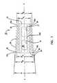
- FIGs. 11-13illustrate a novel tap 80 for use in the method of the present invention.
- the tap 80includes a shaft 81 having an axis X"'-X"'. A distal end of the shaft 81 is provided with a tapping head 82.
- a proximal end of the shaft 81is provided with stop flange 83 for limiting insertion of the tap 80 into a guiding drill tube (not shown).
- the shaft 81includes enlarged diameter portions 84 sized to approximate an internal diameter of a guide tube (not shown) to ensure no relative radial movement of the tap 80 relative to a drill tube as the tap 80 is being axially advanced through a drill tube.
- the novel tapping head 82includes a hollow interior 86 with a closed axial or distal end 88.
- a thread pattern 90surrounds the tapping head 82 but is spaced from the axial end 88 by an unthreaded guide tip 92.
- the threads 90are V-shaped in cross-section and extend from flat valleys 94 to pointed thread tips 96.
- the valleys 94define a conical surface having an internal angle ⁇ " equal to the angle ⁇ of implant 20.
- the tips 96define a conical surface having an internal conical angle equal to ⁇ .
- the depth of the threads 96i.e., the distance between the tips 96 and the valleys 94
- the guide tip 92is cylindrical and has a diameter D T equal to the leading end minor diameter D m of implant 20.
- the starting thread 90'accordingly has a minor diameter of the same size as the minor diameter D M of the starting thread of the implant 20.
- starting thread 90'has a major diameter equal to the leading end major diameter D M .
- the ending thread 90"has a minor diameter equal to the trailing end minor diameter D' m of implant 20.
- the ending thread 90"has a major diameter equal to the major diameter D' M of the implant 20.
- the threadinghas a length L T equal to the length L of the implant 20. Accordingly, the thread pattern 90 is identical in sizing and angles to the thread pattern 26 of implant 20 except for the cross-section profile with threads 96 being V-shaped and with threads 26 being generally square in cross-section (best illustrated comparing FIG. 6 and 13).
- the thread pattern 96includes three cutouts 100 to define cutting edges 102 to permit the threads 96 to tap a thread pattern as the cutting head is rotated in a counterclockwise direction in the view of FIG. 12.
- Channels 104are provided from the cutouts 100 and extending into communication with the hollow interior 86.
- the channels 104define pathways to permit debris formed by the tapping to be accumulated within the interior 86.
- additional channels 106are provided in the valleys 94 between opposing threads.
- the channels 106further extend into communication with the interior 86 to provide additional pathways for debris to flow into the interior 86. Accordingly, during tapping with the tool 80, debris formed by the tapping is accumulated within the interior 86. Due to the closed end 88, the debris is retained within the interior 86 when the tap 80 is removed from the disk space.
- FIGs. 14-17illustrate a driver 110 for use in placing an implant 20 into a prepared space.
- the driver 110includes a shaft 112. A distal end of the shaft 112 is provided with a driving head 114. A proximal end of the shaft 112 is provided with a handle 117.
- the shaft 112is hollow throughout its length defining an axially extending bore 113.
- the handle 117includes a large diameter recess 115 and a narrower diameter recess 119. Recess 119 is threaded for reasons that will become apparent.
- the driving head 114includes axially extending gripping prongs 116,116'.
- the gripping prongs 116,116'are diametrically opposed and are positioned and shaped to be complementary to the cutouts 44,44', respectively of the implant 20.
- the side edges 116b'define an angle ⁇ * slightly less than angle ⁇ while the side edges 116b define an angle ⁇ *' slightly less than angle ⁇ '.
- the angle ⁇ *is about 63° and the angle ⁇ *' would be about 60° to permit minor relative rotational movement of the prongs 116,116' within the cutouts 44,44'.
- the prongs 116,116'include threads 118 positioned and shaped to complete the thread pattern 26 of the implant 20.
- the implant 20may be placed in the driving head 114 with the trailing end 24 abutting the end 112a of the shaft 112 and with the leading end 22 flush with the ends 116a, 116a' the prongs 116,116'.
- the prongs 116a, 116a'cover the sidewall openings 31 of the flat sidewalls 44a, 44a' of the implant 20 such that the implant 20 together with the prongs 116,116' define a continuous externally threaded frusto-conical shape and with the threads 26 aligned with the threads 118 to define a continuous thread pattern.
- a tool 800is shown to hold implant 20 in driver 110.
- the tool 800has a shaft 802, a handle 806 and a threaded end 804. End 804 is threaded into the bore 40 of an implant 20 placed between prongs 116, 116'.
- the handle 806is seated within recess 115 and shaft 802 extends through bore 113 to securely and releasably affix implant 20 within driver 110.
- FIG. 15Bshows a tool 900 for separating the implant 20 from the driver 110.
- the shaft 906 of tool 900is placed in bore 113.
- the blunt end 904abuts the trailing end 24 of the implant 20.
- a threaded portion 908engages the threads of bore 119.
- the blunt end 904urges the implant 20 out from between prongs 116, 116'.
- an L-5 and S-1 vertebraeare shown with a diseased disk space 130 between the opposing end plates 10' 5 and 10 1 .
- disk materialis not shown within the disk space 130.
- the end plates 10' 5 and 10 1are in parallel alignment and are to be distracted (i.e.. separated) as well as being provided with a desired lordosis which in the example is 8°.
- a sagittal plane Sdivides the vertebrae into a left side L and a right side R.
- a preferred surgical approachis an anterior approach performed laparoscopically. Procedures such as removal of disk material are not described or illustrated and are known in the art.
- a selected distraction spacer 50(i.e., a distraction spacer sized and provided with a conical angle selected by the physician to attain a desired distraction and lordosis) is attached to tool 300 with the shaft threaded into the threaded bore 64.
- the distraction spacer 50is forced into space 130 on the left side until the distraction spacer 50 is fully received within the disk space such that the end 58 does not protrude out of the disk space.
- the tool 300is then unthreaded from the distraction spacer 50 and removed through the drill tube leaving the distraction spacer in place.
- the distraction spacer 50urges the disks L-5 and S-1 apart by reason of the conical surface of the distraction spacer urging against the end plates 10' 5 and 10 1 .
- the distraction plug 50induces a desired lordosis of 8° to the vertebrae L-5 and S-1 as illustrated in FIG. 20.
- a drill tube(not shown but which may be such as that shown in U.S. Patent No. 5,489,307) is placed on the right side of the disk space 130.
- a boreis then formed partially into the opposing vertebrae L-5 and S-1 as illustrated in FIG. 21.
- the pre-boring tool 70 with an attached guide pin 200is first inserted into drill tube. The guide point acts against the opposing surfaces of the end plates 10 5 ', 10, to initially centrally align the boring tool 70 within the disk space 130.
- the cutting head 72By rotating the pre-boring tool 70, the cutting head 72 cuts an initial depth of a bore into the vertebrae L-5, S-1. Due to guide 200, a bore is cut by head 72 only about 50% of the way into the disk space.
- pre-boring toolssuch as tool 70 having guide pins to initially form a bore between opposing vertebrae is not part of this invention per se and is disclosed and described in U.S. Patent No. 5,489,307.
- the '307 patentfurther discloses forming a final bore with a final boring tool. Since the vertebrae L-5 and S-1 are distracted with a lordosis of 8° and the boring tools having cutting heads which are tapered, a bore is only partially cut into the vertebrae by the pre-boring tool with no bore formation at the posterior ends of the vertebrae L-5, S-1. The posterior end will be simultaneously bored and tapped by the debris retaining tap.
- the tap 80is inserted into the drill tube as illustrated in FIG. 22.
- the minor diameter of the threads of the tap 80will be substantially equal to the spacing of the end plates such that the V-shaped threads 90 of the tap only cut into the end plates 10 5 ', 10, as illustrated in FIG. 22.
- the tap 80Since the tap 80 is provided with a conical angle substantially equal to the angled separation of the distracted vertebrae, the tap 80 forms a tapped bore between the vertebrae L-5, S-1 with a thread pattern matching the thread pattern of the implant 20. After removal of the tap, debris formed in the tapping process is removed from the disk space 130 by reason of the debris being captured within the interior 86 of the tapping head 82.
- the implant 20is inserted into the distal end of the driver 110 and retained therein by tool 802.
- the implant 20is filled with bone or other suitable bone growth inducing substance.
- the driver 110 and attached implant 20are then inserted through the drill tube and threadedly urged into the pre-tapped bore between the vertebrae L-5 and S-1.
- the pre-tapped borematches the size and thread pattern of the implant 20 except only that the pre-tapped threads of the bore are V-shaped and the threads 26 of the implant 20 are square in cross-section.
- Rotation of the implant and driver within the disk spaceis continued until the implant 20 is fully inserted within the disk space 130 and the prongs 116,116a' are aligned with the disk space 130. With the prongs 116, 116a' so aligned, the holes 32 directly oppose the bone of the vertebrae L-5, S-1.
- the implant 20 and boring and tapping tools 110, 80are sized such that the tapping exposes the cancellous bone of the vertebrae to encourage bone growth from the vertebrae through the implant and in communication with any bone growth inducing substance placed within the interior 30 of the implant. Also, the threads 26 of the implant 20 will be opposing and retained within the cortical bone of the vertebrae L-5, S-1 to resist subsidence of the implant 20 into the vertebrae.
- FIG. 24illustrates an implant 20 inserted between the vertebrae L-5, S-1 on the right side and with a distraction spacer 50 still in place on the left side.
- the guide tubemay be moved to the left side.
- the distraction spacer 50may then be removed and the left side may be prepared for implant insertion by boring and tapping as described above and a second implant may be placed in the left side.
- the implant 400can be used with the tools and methods described above.
- the implant 400has a first and second taper and a longitudinal axis X-X extending from a leading end 401 to a trailing end 402.
- the trailing end 402 of the present embodimentcomprises a "trailing end rise" (TER) 403 and a terminal end 404.
- the first taper of implant 400diverges from the axis from the leading end 401 to the trailing end rise 403 of the trailing end 402.
- the second taperdiverges from the axis from the terminal end 404 to the TER 403.
- the trailing end riseis the region of greatest diameter of the implant 400.
- the second taperprovides implantation advantages for the surgeon as well as increased safety for the patient.
- the bi-tapered implant 400includes leading end 401 having a first taper providing a substantially frusto-conical shape with a conical angle ⁇ equal to a desired lordosis between selected vertebrae.
- the angle ⁇ of the illustrated embodiment, measured from the leading end 401 to the TER 403is 8°, however, as described for other embodiments of the invention, the implants will be available with a variety of angles and sizes.
- leading end 401has a major diameter D M measured between diametrically opposite outer radial surfaces 405a of the threads 405 at the leading end 401.
- the leading end 401also has a minor diameter D m measured between diametrically opposite inner radial surfaces 408a of the valleys 408 of the thread pattern 405 of implant 400.
- the implant 400has a major diameter D' M measured between diametrically opposite outer radial surfaces 405b of threads 405 at the trailing end rise 403.
- the trailing end 402also has a minor diameter D E measured across terminal end 404.
- the second taper of implant 400has a second angle, ⁇ , extending from the terminal end 404 to the TER 403.
- the angle ⁇will vary with the diameter D' M of the TER 403, the diameter D E of the terminal end 404, and the longitudinal distance L E therebetween.
- the diameter D E of the terminal end 404is equal to the major diameter D M of the leading end 401.
- the longitudinal distance L Ecan be about 5% to 25% of the overall length L of the implant. Generally, L E is less than 15% of the overall length L, typically about 8-10%.
- mis about 1 (45°).
- the actual slope dimension mcan vary, typically, between .58 (30°) and 1.73 (60°).
- the helical threads 405can extend along the second taper as illustrated at 406 of FIGs. 25-27. Alternatively, as illustrated in FIG. 28, the threads 405 can stop at the terminal rise 403 and the second taper comprise a flat 410, undulating or other non-thread bearing surface, from trailing end rise 403 to terminal end 404.
- FIGs. 29 and 30illustrate the terminal end and leading end, respectively, of implant 400. Other features described for the implant embodiment 20 are also applicable to implant 400.
- the second taper of implant 400provides installation advantages for the surgeon and enhanced safety features for the patient.
- the trailing end taperallows a greater margin of error in the desired length of the bore formed for inserting the implant. That is, in some circumstances, if the length of the bore formed is less than the length of the implant, the tapered trailing end 402 permits insertion of implant 400 into the "short" bore without leaving a trailing end exposed beyond the surface of the vertebrae that has a sharp or abrupt edge.
- the tapered trailing end of implant 400facilitates re-engaging the implant driver to adjust the anterior/posterior position of the implant.
- the second taper at the trailing endreduces the likelihood that the trailing end would erode through major blood vessels, the peritoneum or other structures surrounding the implanted device.
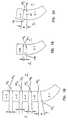
- FIGs. 31-36illustrate additional embodiments of a distraction spacer ("plug") suitable for use with lordotic implants or non-tapered type implants.
- FIG. 31is a side elevation view of a ramp distraction spacer 250, the opposite side being identical in appearance.
- the spacer 250has a main body portion 252 with a leading end 253.
- the ramp surface 254 of spacer 250is shown in FIG. 31. In transverse cross section, the region of the main body 252 and leading end 253 between the ramp surfaces 254 can be arcuate. It will be appreciated that ramp surface(s) 254 includes knurls 255 to reduce the chance of undesired movement following placement of distraction spacer 250 into a disk space.
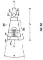
- Fig 32is a right side elevation of the distraction spacer 250 rotated 90° around longitudinal axis X'-X' from the view in FIG. 31.
- the opposite side of the view of FIG. 32is identical in appearance.
- a front view of the tapered surface 256 of the leading end 253is shown in FIG. 32.
- the relationship of the ramp surfaces 254 and the tapered surfaces 256 at the leading end 253is illustrated in FIG. 33. It will be appreciated that the leading end tip 257 need not be circular but can, for example, be oval in shape.
- the ramp surfaces 254 of the distraction spacer 250are symmetrically opposed about the longitudinal axis X'-X' and form a ramp angle of ⁇ .
- the angle ⁇ and leading end tip 257 sizeare selected to permit ease of insertion of the distraction spacer 250 into the disk space.
- the distraction spaceris sized to have a main body 252 outer diameter D o substantially equal to the midline disk height of a healthy disk in the patient being treated.
- the axial length L' of the distraction spacer 250is approximate to the length L of the implant and sized for the distraction spacer 250 to be fully inserted into the disk space without protruding beyond the vertebrae.
- Leading end 253can also include a bore 260 which passes through opposing tapered surfaces 256.
- the bore 260provides for insertion of pin 351 of T-device 350 illustrates in FIG. 37.
- T-device 350can facilitate removal of the spacer 250 from, for example, tool 300 illustrated in FIG. 7A.
- the T-device 350also includes a handle 352 for grasping the device.
- the distraction spacer 250includes an annular groove 261 to permit a surgeon to grasp the distraction spacer if needed.
- the trailing end 270is provided with an internally threaded axial bore 272 for attachment of a placement tool 300.
- FIG. 34is a side elevation view of another embodiment of a ramp distraction spacer 500, the opposite side being identical in appearance.
- the spacer 500has a main body portion 501 with a leading end 502.
- FIG. 35is a side elevation view of the distraction spacer 500 rotated 90° around longitudinal axis X'-X' from the view in FIG. 34, the opposite side of the view being identical in appearance.
- FIG. 35illustrates the ramp surface 503 of spacer 500 including knurls 510. It will be appreciated that the embodiment of distraction spacer 500 dies not include the annular groove 261 present in distraction spacer 250 ( see FIGs. 31-33).
- tapered surface 504 of leading end 502 and ramp surfaces 503are illustrated in the front end view of FIG. 36.
- a bore 505may also be present for operation of T-device 350.
- the leading end tip 508 of the illustrated embodiment of implant 500is circular.
- kits containing numerous sized implantscan be provided with numerous sized distraction spacers having various ramp angles.
- implantsmay maintain or increase lordosis. Further, the present invention permits formation of a tapped hole while removing debris which would otherwise obstruct implant insertion. With the present invention, precise identity of depth of insertion of an implant on the left and the right side need not be attained, permitting greater versatility and tolerance of the surgical method to inaccuracies.
Landscapes
- Health & Medical Sciences (AREA)
- Engineering & Computer Science (AREA)
- Biomedical Technology (AREA)
- Orthopedic Medicine & Surgery (AREA)
- Life Sciences & Earth Sciences (AREA)
- Transplantation (AREA)
- General Health & Medical Sciences (AREA)
- Public Health (AREA)
- Oral & Maxillofacial Surgery (AREA)
- Heart & Thoracic Surgery (AREA)
- Veterinary Medicine (AREA)
- Neurology (AREA)
- Animal Behavior & Ethology (AREA)
- Vascular Medicine (AREA)
- Cardiology (AREA)
- Surgery (AREA)
- Physical Education & Sports Medicine (AREA)
- Dentistry (AREA)
- Nuclear Medicine, Radiotherapy & Molecular Imaging (AREA)
- Medical Informatics (AREA)
- Molecular Biology (AREA)
- Prostheses (AREA)
- Surgical Instruments (AREA)
Description
FIG. 24 illustrates an
Claims (32)
- A kit for placing an implant (20, 400) into a disk space (130) betweenopposing vertebrae having opposing end plates (105', 101) to be separated by apredetermined degree of lordosis, said kit comprising:characterized in thatan implant (20, 400) having:a hollow body having a leading end (22, 401) and a trailing end(24, 402) with a leading end implant diameter (DM) at said leading end (22,401) and a trailing end implant diameter (DM') at said trailing end (24, 402),said trailing end implant diameter (DM') being greater than said leading endimplant diameter (DM);an implant thread pattern (26, 405) surrounding said body;openings (32) formed through a wall of said body into an interior(30) of said body with said openings (32) formed at least on diametricallyopposite sides of said body;a tap (80) having:a shaft (81) defining a longitudinal axis (X"'-X"');a tapping head (82) at a distal end of said shaft (81), said tappinghead (82) having a tapping thread (90) surrounding said axis (X"'-X"') with athread pattern (90) substantially matching said implant thread pattern (26);said tapping thread (90) includes a plurality of peaks (96) andvalleys (94);and a leading end tap diameter which is substantially equal tosaid leading end implant diameter (Dm),
the implant's body is of generally frusto-conical shape, having aconical angle (α) approximating said degree of lordosis; and
the tap's tapping thread (90) defines a conical path around saidaxis (X"'-X"') with a leading end tap diameter (DT) adjacent said distal end andwith a trailing end tap diameter spaced from said distal end, said trailing endtap diameter being greater than said leading end tap diameter (DT); - A kit according to claim 1, wherein
said tapping head (82) includes a hollow body defining a tap interior (86);
a plurality of channels (104, 106) for directing tapped debris from saidtapping thread (90) into said tap interior (86). - A kit according to claim 2, wherein said tapping thread (90) includes aplurality a axially extending grooves (100) through said thread (90), saidchannels (104) formed through said grooves (100) and into said interior (86).
- A kit according to claim 2, wherein said channels (106) are formedthrough said valleys (94).
- A kit according to claim 2, wherein an axial end (88) of said interior (86)is closed at said distal end.
- A kit according to claim 1, wherein said implant thread (26, 405) has agenerally flat radial extremity (26a, 405a,b) in a surface of a cone defined bysaid implant thread (26, 405).
- A kit according to claim 6, wherein said tapping thread (90) has a sharpradial extremity (96).
- A kit according to claim 1, further comprising a distraction spacer (50,250, 500) having:a rigid spacer body (52, 252, 501);
said body (52, 252, 501) having at least diametrically oppositeexterior surfaces defining an angle (α', γ) substantially equal to said degree oflordosis. - A kit according to claim 8 wherein said surfaces of said distractionspacer are disposed on a substantially continuous outer surface of said bodysymmetrically about a longitudinal axis (X'-X') of said body.
- A kit according to claim 1, further comprising a distraction spacer (250, 500) for placing an implant (20, 400) into a disk space (130) between opposingvertebrae having opposing end plates separated by a predetermined degree oflordosis, said distraction spacer (250, 500) comprising:a main body (252, 501);first and second diametrically opposed surfaces having a leading end(253, 502) and a trailing (270) with a longitudinal axis (X'-X') passingtherethrough;said first and second diametrically opposed surfaces (254, 503)converging towards said longitudinal axis (X'-X') from said trailing end (270) tosaid leading end (253, 502).
- A kit according to claim 10, wherein said main body (252, 501) of thedistraction spacer (250, 500) is a frusto-conical shaped and said first andsecond diametrically opposed surfaces (254, 503) are portions of said frusto-conicalshape.
- A kit according to claim 10, wherein said first and second diametricallyopposed surfaces (254, 503) of the distraction spacer are flat surfaces.
- A kit according to claim 12, wherein said main body (252, 501) betweensaid diametrically opposed surfaces is arcuate.
- A kit according to claim 10, wherein the distraction spacer (250) furtherincludes an internal axial threaded bore (272) at said trailing end (270).
- A kit according to claim 13, wherein the distraction spacer (250, 500)further includes a bore (260, 505) passing through said diametrically opposedarcuate surfaces (256, 504).
- A kit according to claim 1, wherein sides of said implant body betweensaid diametrically opposite sides are recessed inwardly from a cone defined bysaid frusto-conical body to define first and second recesses (44, 44'), said kitfurther comprising a driver (110) for advancing said implant (20, 400), saiddriver (110) having:a driver shaft (112) having first and second prong members (116, 116') ata distal end of said shaft (112);said first and second prong members (116, 116') axially extending fromsaid driver shaft (112) and sized to be received within said first and secondrecesses (44, 44') with said implant (20, 400) positioned between said prongmembers (116, 116') and with a longitudinal axis (X-X) of said implant (20, 400)aligned with a longitudinal axis (X-X) of said driver shaft (112).
- A kit according to claim 16, wherein said prong members (116, 116')include external threads (118) sized and disposed to match and complete saidimplant thread pattern (26, 405) when said implant (20, 400) is receivedbetween said prong members (116, 116').
- A kit according to claim 1, further comprising a boring tool (70) having atapered cutting head (72) for cutting a tapered bore between said vertebrae.
- A kit according to claim 1, wherein the tapping thread (90) of the tap(80) is arranged for forming a thread receiving groove in opposing surfaces ofsaid vertebrae (L,S), said tapping head (82) further including
a hollow body defining a tap interior (86); and
a plurality of channels (104, 106) for directing tapped debris, generatedby the tapping thread (90) as the tapping head (82) is rotated about its axis(X"'-X"'), from said tapping threads (90) into said tap interior (86). - A kit according to claim 19, wherein said tapping head (82) includes aguide (92) on said distal end.
- A kit according to claim 20, wherein said guide (92) is a cylindricalsurface coaxially disposed on said leading end.
- A kit according to claim 21, wherein said cylindrical surface has adiameter (DT) approximate said leading end tap diameter.
- A kit according to claim 19, wherein said peaks (96) cooperate to define afirst conical surface and said valleys (94) cooperate to define a second conicalsurface parallel to said first conical surface.
- A kit according to claim 1, wherein the sides of said body of said implant(20, 400) between said diametrically opposite sides are recessed (44, 44')inwardly from a cone defined by said frusto-conical body.
- A kit according to claim 1, wherein the implant (20, 400) for placementinto a disk space (130) between opposing vertebrae having opposing end platesto be separated by a predetermined degree of lordosis where said end plates aredistracted to a desired degree of lordosis with a tap thread pattern (90) withinsaid opposing vertebra with said tap thread pattern (90) being a segment of acone having a conical angle (α") substantially equal to said predetermineddegree of lordosis, said implant (20, 400) comprising:a generally frusto-conical body having a leading end (22, 401) with aleading end implant diameter (DM) and a trailing end (24, 402) with a trailingend implant diameter (DM'), said trailing end implant diameter (DM') beinggreater than said leading end implant diameter (DM);said frusto-conical body having a conical angle (a) approximating saiddegree of lordosis;an implant thread pattern (26, 405) surrounding said body sized andpositioned to threadedly mate with said tap thread pattern (90).
- A kit according to claim 1 wherein said end plates of the opposingvertebrae are distracted to a desired degree of lordosis with a tap threadpattern (90) within said opposing vertebra with said tap thread pattern (90)being a segment of a cone having a conical angle (α") substantially equal to saidpredetermined degree of lordosis, and wherein the thread pattern (26, 405)surrounding the body of the implant (20, 400) is sized and positioned tothreadedly mate with the tap thread pattern (90).
- A kit according to claim 26, wherein said body is hollow and saidbody includes openings (32) formed through a conical wall of said body into aninterior (30) of said body with said openings (32) formed at least ondiametrically opposite sides of said body.
- A kit according to claim 1, wherein the trailing end (402) of the implant(400) comprises:a trailing end rise (403) having a trailing end rise diameter (DM'); anda terminal end (404) having a terminal end diameter (DE); and the hollow body of the implant (400) comprises:a first taper increasing from said leading end diameter (DM) to saidtrailing end rise diameter (DM'); anda second taper increasing from said terminal end diameter (DE) to saidtrailing end rise diameter (DM').
- A kit according to claim 28, wherein the implant (400) comprises animplant thread pattern (405) surrounding said body;
openings formed through a conical wall of said body into an interiorof said body with said openings formed at least on diametrically opposite sidesof said body. - A kit according to claim 29, wherein sides of said body between saiddiametrically opposite sides are recessed inwardly from a cone defined by saidfrusto-conical body.
- A kit, according to any one of the preceding claims comprising an implant forplacement into a disk space (130) between opposing vertebrae having opposingendplates to be separated by a predetermined degree of lordosis, said implant(400) comprising:(A) a generally frusto-conical hollow body having:(1) a leading end (401) with a leading end diameter (DM);(2) a trailing end (402) comprising:a trailing end rise (403) having a trailing end rise diameter(DM'); anda terminal end (404) having a terminal end diameter (DE);(3) a first taper increasing from said leading end diameter (DM) tosaid trailing end rise diameter (DM'); and(4) a second taper increasing from said terminal end diameter (DE) tosaid trailing end rise diameter (DM').
- A kit according to any one of claims 1-30, comprising a distraction spacer forplacing an implant (20, 400) into a disk space (130) between opposing vertebrae having opposing end plates separated by a predetermined degree of lordosis,said distraction spacer (250, 500) comprising:a main body (252, 501);first and second diametrically opposed flat surfaces having a leadingend (253, 502) and a trailing (270) with a longitudinal axis (X'-X') passingtherethrough;said first and second diametrically opposed surfaces (254, 503)converging towards said longitudinal axis (X'-X') from said trailing end (270) tosaid leading end (253, 502);wherein the main body (252, 501) between said diametrically opposedsurfaces is arcuate; and includes a bore (260, 505) passing through saiddiametrically opposed arcuate surfaces (256, 504).
Applications Claiming Priority (3)
| Application Number | Priority Date | Filing Date | Title |
|---|---|---|---|
| US81279197A | 1997-03-06 | 1997-03-06 | |
| US812791 | 1997-03-06 | ||
| PCT/US1998/004405WO1998038924A2 (en) | 1997-03-06 | 1998-03-06 | Lordotic spinal implant |
Publications (2)
| Publication Number | Publication Date |
|---|---|
| EP1011481A2 EP1011481A2 (en) | 2000-06-28 |
| EP1011481B1true EP1011481B1 (en) | 2004-10-27 |
Family
ID=25210639
Family Applications (1)
| Application Number | Title | Priority Date | Filing Date |
|---|---|---|---|
| EP19980910201Expired - LifetimeEP1011481B1 (en) | 1997-03-06 | 1998-03-06 | Lordotic spinal implant |
Country Status (8)
| Country | Link |
|---|---|
| US (6) | US5897593A (en) |
| EP (1) | EP1011481B1 (en) |
| JP (1) | JP2001514542A (en) |
| AU (1) | AU6449898A (en) |
| CA (1) | CA2283166C (en) |
| DE (1) | DE69827280T2 (en) |
| ES (1) | ES2231969T3 (en) |
| WO (1) | WO1998038924A2 (en) |
Cited By (3)
| Publication number | Priority date | Publication date | Assignee | Title |
|---|---|---|---|---|
| US9216096B2 (en) | 2010-03-16 | 2015-12-22 | Pinnacle Spine Group, Llc | Intervertebral implants and related tools |
| US9380932B1 (en) | 2011-11-02 | 2016-07-05 | Pinnacle Spine Group, Llc | Retractor devices for minimally invasive access to the spine |
| US10070970B2 (en) | 2013-03-14 | 2018-09-11 | Pinnacle Spine Group, Llc | Interbody implants and graft delivery systems |
Families Citing this family (306)
| Publication number | Priority date | Publication date | Assignee | Title |
|---|---|---|---|---|
| US6245072B1 (en) | 1995-03-27 | 2001-06-12 | Sdgi Holdings, Inc. | Methods and instruments for interbody fusion |
| US6206922B1 (en)* | 1995-03-27 | 2001-03-27 | Sdgi Holdings, Inc. | Methods and instruments for interbody fusion |
| US5782919A (en)* | 1995-03-27 | 1998-07-21 | Sdgi Holdings, Inc. | Interbody fusion device and method for restoration of normal spinal anatomy |
| US20050165483A1 (en)* | 2004-01-27 | 2005-07-28 | Ray Eddie F.Iii | Bone grafts |
| US5897593A (en)* | 1997-03-06 | 1999-04-27 | Sulzer Spine-Tech Inc. | Lordotic spinal implant |
| US6033438A (en)* | 1997-06-03 | 2000-03-07 | Sdgi Holdings, Inc. | Open intervertebral spacer |
| FR2767675B1 (en)* | 1997-08-26 | 1999-12-03 | Materiel Orthopedique En Abreg | INTERSOMATIC IMPLANT AND ANCILLARY OF PREPARATION SUITABLE FOR ALLOWING ITS POSITION |
| US6511509B1 (en) | 1997-10-20 | 2003-01-28 | Lifenet | Textured bone allograft, method of making and using same |
| US20010001129A1 (en)* | 1997-12-10 | 2001-05-10 | Mckay William F. | Osteogenic fusion device |
| FR2772594B1 (en)* | 1997-12-19 | 2000-05-05 | Henry Graf | REAR PARTIAL DISCAL PROSTHESIS |
| US6033407A (en)* | 1998-01-27 | 2000-03-07 | Behrens; Alfred F. | Apparatus and method for intramedullary nailing and intramedullary nail therefor |
| US6143033A (en)* | 1998-01-30 | 2000-11-07 | Synthes (Usa) | Allogenic intervertebral implant |
| US6986788B2 (en)* | 1998-01-30 | 2006-01-17 | Synthes (U.S.A.) | Intervertebral allograft spacer |
| USRE38614E1 (en)* | 1998-01-30 | 2004-10-05 | Synthes (U.S.A.) | Intervertebral allograft spacer |
| US6224631B1 (en)* | 1998-03-20 | 2001-05-01 | Sulzer Spine-Tech Inc. | Intervertebral implant with reduced contact area and method |
| US6241729B1 (en)* | 1998-04-09 | 2001-06-05 | Sdgi Holdings, Inc. | Method and instrumentation for posterior interbody fusion |
| US6008433A (en)* | 1998-04-23 | 1999-12-28 | Stone; Kevin R. | Osteotomy wedge device, kit and methods for realignment of a varus angulated knee |
| US6241769B1 (en)* | 1998-05-06 | 2001-06-05 | Cortek, Inc. | Implant for spinal fusion |
| US6290724B1 (en) | 1998-05-27 | 2001-09-18 | Nuvasive, Inc. | Methods for separating and stabilizing adjacent vertebrae |
| US6368325B1 (en)* | 1998-05-27 | 2002-04-09 | Nuvasive, Inc. | Bone blocks and methods for inserting bone blocks into intervertebral spaces |
| US6251140B1 (en) | 1998-05-27 | 2001-06-26 | Nuvasive, Inc. | Interlocking spinal inserts |
| US6083228A (en)* | 1998-06-09 | 2000-07-04 | Michelson; Gary K. | Device and method for preparing a space between adjacent vertebrae to receive an insert |
| EP1681021A3 (en)* | 1998-06-09 | 2009-04-15 | Warsaw Orthopedic, Inc. | Abrading element for preparing a space between adjacent vertebral bodies |
| US20060241763A1 (en)* | 1998-08-03 | 2006-10-26 | Synthes (Usa) | Multipiece bone implant |
| DK1100417T3 (en) | 1998-08-03 | 2004-08-02 | Synthes Ag | Intervertebral allograft spacer |
| US6174311B1 (en) | 1998-10-28 | 2001-01-16 | Sdgi Holdings, Inc. | Interbody fusion grafts and instrumentation |
| US6193757B1 (en) | 1998-10-29 | 2001-02-27 | Sdgi Holdings, Inc. | Expandable intervertebral spacers |
| EP1131020B1 (en)* | 1998-10-30 | 2005-04-20 | Gary Karlin Michelson | Self-broaching, rotatable, push-in interbody fusion implant |
| BR9805340B1 (en) | 1998-12-14 | 2009-01-13 | variable expansion insert for spinal stabilization. | |
| DE60022620T2 (en)* | 1999-01-11 | 2006-06-22 | SDGI Holdings, Inc., Wilmington | INTERMEDIATE SPACER WITH ACCESSIBLE INTERIOR THROUGH SIDE WALLS |
| US6325827B1 (en) | 1999-02-01 | 2001-12-04 | Blacksheep Technologies, Inc. | Intervertebral implant |
| AU761818C (en)* | 1999-02-04 | 2004-05-27 | Warsaw Orthopedic, Inc. | Methods and instrumentation for vertebral interbody fusion |
| US6743234B2 (en)* | 1999-02-04 | 2004-06-01 | Sdgi Holdings, Inc. | Methods and instrumentation for vertebral interbody fusion |
| US6648895B2 (en)* | 2000-02-04 | 2003-11-18 | Sdgi Holdings, Inc. | Methods and instrumentation for vertebral interbody fusion |
| CA2361068A1 (en)* | 1999-02-04 | 2000-08-10 | Sdgi Holdings, Inc. | Improved interbody fusion device with anti-rotation features |
| US6241770B1 (en)* | 1999-03-05 | 2001-06-05 | Gary K. Michelson | Interbody spinal fusion implant having an anatomically conformed trailing end |
| CA2363254C (en) | 1999-03-07 | 2009-05-05 | Discure Ltd. | Method and apparatus for computerized surgery |
| US6159179A (en) | 1999-03-12 | 2000-12-12 | Simonson; Robert E. | Cannula and sizing and insertion method |
| US6342074B1 (en) | 1999-04-30 | 2002-01-29 | Nathan S. Simpson | Anterior lumbar interbody fusion implant and method for fusing adjacent vertebrae |
| US20060247665A1 (en) | 1999-05-28 | 2006-11-02 | Ferree Bret A | Methods and apparatus for treating disc herniation and preventing the extrusion of interbody bone graft |
| US7273497B2 (en)* | 1999-05-28 | 2007-09-25 | Anova Corp. | Methods for treating a defect in the annulus fibrosis |
| US6969404B2 (en) | 1999-10-08 | 2005-11-29 | Ferree Bret A | Annulus fibrosis augmentation methods and apparatus |
| US6491724B1 (en)* | 1999-08-13 | 2002-12-10 | Bret Ferree | Spinal fusion cage with lordosis correction |
| US20070038231A1 (en) | 1999-05-28 | 2007-02-15 | Ferree Bret A | Methods and apparatus for treating disc herniation and preventing the extrusion of interbody bone graft |
| US6419705B1 (en)* | 1999-06-23 | 2002-07-16 | Sulzer Spine-Tech Inc. | Expandable fusion device and method |
| US6936071B1 (en) | 1999-07-02 | 2005-08-30 | Spine Solutions, Inc. | Intervertebral implant |
| US6283966B1 (en)* | 1999-07-07 | 2001-09-04 | Sulzer Spine-Tech Inc. | Spinal surgery tools and positioning method |
| DE60030989T2 (en)* | 1999-08-26 | 2007-05-24 | Warsaw Orthopedic, Inc., Warsaw | DEVICE FOR IMPLANTING FUSION CAGE |
| EP1792586B1 (en) | 1999-09-14 | 2012-12-26 | Spine Solutions Inc. | Insert instrument for an implant between vertebrae |
| US20030004574A1 (en)* | 1999-10-08 | 2003-01-02 | Ferree Bret A. | Disc and annulus augmentation using biologic tissue |
| US20040186573A1 (en)* | 1999-10-08 | 2004-09-23 | Ferree Bret A. | Annulus fibrosis augmentation methods and apparatus |
| US6500180B1 (en)* | 1999-10-20 | 2002-12-31 | Sdgi Holdings, Inc. | Methods and instrumentation for distraction of a disc space |
| US6575899B1 (en) | 1999-10-20 | 2003-06-10 | Sdgi Holdings, Inc. | Methods and instruments for endoscopic interbody surgical techniques |
| US6592625B2 (en)* | 1999-10-20 | 2003-07-15 | Anulex Technologies, Inc. | Spinal disc annulus reconstruction method and spinal disc annulus stent |
| US6592624B1 (en) | 1999-11-24 | 2003-07-15 | Depuy Acromed, Inc. | Prosthetic implant element |
| ES2270888T3 (en)* | 1999-12-01 | 2007-04-16 | Henry Graf | INTERVERTEBRAL STABILIZATION DEVICE. |
| US7182781B1 (en)* | 2000-03-02 | 2007-02-27 | Regeneration Technologies, Inc. | Cervical tapered dowel |
| US6821298B1 (en)* | 2000-04-18 | 2004-11-23 | Roger P. Jackson | Anterior expandable spinal fusion cage system |
| US7462195B1 (en) | 2000-04-19 | 2008-12-09 | Warsaw Orthopedic, Inc. | Artificial lumbar interbody spinal implant having an asymmetrical leading end |
| EP1284707A4 (en) | 2000-05-30 | 2003-06-25 | Paul S Lin | Implant for placement between cervical vertebrae |
| USD493225S1 (en) | 2000-06-12 | 2004-07-20 | Ortho Development Corporation | Implant |
| US6579318B2 (en) | 2000-06-12 | 2003-06-17 | Ortho Development Corporation | Intervertebral spacer |
| AU2001280476B2 (en) | 2000-06-30 | 2005-11-24 | Stephen Ritland | Polyaxial connection device and method |
| US7018416B2 (en) | 2000-07-06 | 2006-03-28 | Zimmer Spine, Inc. | Bone implants and methods |
| US6852126B2 (en) | 2000-07-17 | 2005-02-08 | Nuvasive, Inc. | Stackable interlocking intervertebral support system |
| US6626905B1 (en)* | 2000-08-02 | 2003-09-30 | Sulzer Spine-Tech Inc. | Posterior oblique lumbar arthrodesis |
| US6821280B1 (en) | 2000-08-03 | 2004-11-23 | Charanpreet S. Bagga | Distracting and curetting instrument |
| US20050049587A1 (en)* | 2003-08-27 | 2005-03-03 | Jackson Roger P. | Threaded device for implantation between vertebrae |
| US7833250B2 (en) | 2004-11-10 | 2010-11-16 | Jackson Roger P | Polyaxial bone screw with helically wound capture connection |
| US7195643B2 (en)* | 2003-08-29 | 2007-03-27 | Jackson Roger P | Convex spinal fusion interbody spacer |
| US6666888B1 (en) | 2000-08-23 | 2003-12-23 | Roger P. Jackson | Threaded fusion cage with enhanced anterior support |
| US8535378B2 (en)* | 2004-05-10 | 2013-09-17 | Roger P. Jackson | Vertebral interbody spacer |
| US6824565B2 (en)* | 2000-09-08 | 2004-11-30 | Nabil L. Muhanna | System and methods for inserting a vertebral spacer |
| US8628575B2 (en) | 2000-08-29 | 2014-01-14 | Nabil L. Muhanna | Vertebral body replacement and method of use |
| US6500206B1 (en)* | 2000-09-15 | 2002-12-31 | Donald W. Bryan | Instruments for inserting spinal vertebral implant |
| US6443987B1 (en) | 2000-09-15 | 2002-09-03 | Donald W. Bryan | Spinal vertebral implant |
| EP1328217A2 (en)* | 2000-09-19 | 2003-07-23 | SDGI Holdings, Inc. | Osteogenic fusion devices |
| US20020038123A1 (en)* | 2000-09-20 | 2002-03-28 | Visotsky Jeffrey L. | Osteotomy implant |
| USD458373S1 (en) | 2000-09-21 | 2002-06-04 | Roger P. Jackson | Interbody spinal implant |
| US7166073B2 (en) | 2000-09-29 | 2007-01-23 | Stephen Ritland | Method and device for microsurgical intermuscular spinal surgery |
| US6692434B2 (en) | 2000-09-29 | 2004-02-17 | Stephen Ritland | Method and device for retractor for microsurgical intermuscular lumbar arthrodesis |
| ATE385742T1 (en) | 2000-10-24 | 2008-03-15 | Howmedica Osteonics Corp | BARRELS-SHAPED THREADED DEVICE FOR FUSING ADJACENT BONE STRUCTURES |
| WO2002034170A2 (en)* | 2000-10-24 | 2002-05-02 | Howmedica Osteonics Corp. | Barrel-shaped apparatus for fusing adjacent bone structure |
| US6440170B1 (en)* | 2000-12-04 | 2002-08-27 | Roger P. Jackson | Threaded interbody device |
| US6443989B1 (en)* | 2000-12-04 | 2002-09-03 | Roger P. Jackson | Posterior expandable fusion cage |
| US6773460B2 (en)* | 2000-12-05 | 2004-08-10 | Roger P. Jackson | Anterior variable expandable fusion cage |
| US8083768B2 (en)* | 2000-12-14 | 2011-12-27 | Ensure Medical, Inc. | Vascular plug having composite construction |
| US6692501B2 (en)* | 2000-12-14 | 2004-02-17 | Gary K. Michelson | Spinal interspace shaper |
| US20020169507A1 (en)* | 2000-12-14 | 2002-11-14 | David Malone | Interbody spine fusion cage |
| US6623509B2 (en) | 2000-12-14 | 2003-09-23 | Core Medical, Inc. | Apparatus and methods for sealing vascular punctures |
| US6896692B2 (en) | 2000-12-14 | 2005-05-24 | Ensure Medical, Inc. | Plug with collet and apparatus and method for delivering such plugs |
| US6890343B2 (en)* | 2000-12-14 | 2005-05-10 | Ensure Medical, Inc. | Plug with detachable guidewire element and methods for use |
| US6846319B2 (en)* | 2000-12-14 | 2005-01-25 | Core Medical, Inc. | Devices for sealing openings through tissue and apparatus and methods for delivering them |
| US6520993B2 (en) | 2000-12-29 | 2003-02-18 | Depuy Acromed, Inc. | Spinal implant |
| US6929606B2 (en)* | 2001-01-29 | 2005-08-16 | Depuy Spine, Inc. | Retractor and method for spinal pedicle screw placement |
| WO2002060330A1 (en) | 2001-01-29 | 2002-08-08 | Stephen Ritland | Retractor and method for spinal pedicle screw placement |
| US20020138147A1 (en)* | 2001-03-22 | 2002-09-26 | Surgical Dynamics, Inc. | Apparatus for fusing adjacent bone structures |
| US6890355B2 (en) | 2001-04-02 | 2005-05-10 | Gary K. Michelson | Artificial contoured spinal fusion implants made of a material other than bone |
| US20040083002A1 (en)* | 2001-04-06 | 2004-04-29 | Belef William Martin | Methods for treating spinal discs |
| US6974480B2 (en) | 2001-05-03 | 2005-12-13 | Synthes (Usa) | Intervertebral implant for transforaminal posterior lumbar interbody fusion procedure |
| US6719794B2 (en)* | 2001-05-03 | 2004-04-13 | Synthes (U.S.A.) | Intervertebral implant for transforaminal posterior lumbar interbody fusion procedure |
| US7862587B2 (en) | 2004-02-27 | 2011-01-04 | Jackson Roger P | Dynamic stabilization assemblies, tool set and method |
| EP1417000B1 (en) | 2001-07-11 | 2018-07-11 | Nuvasive, Inc. | System for determining nerve proximity during surgery |
| US6554864B2 (en)* | 2001-07-16 | 2003-04-29 | Spinecore, Inc | Surgical method of treating scoliosis |
| US8038717B2 (en)* | 2001-07-16 | 2011-10-18 | Spinecore, Inc. | Method of distracting vertebral bones |
| US6436102B1 (en)* | 2001-07-16 | 2002-08-20 | Third Millennium Engineering, Llc | Method of distracting vertebral bones |
| US6471725B1 (en)* | 2001-07-16 | 2002-10-29 | Third Millenium Engineering, Llc | Porous intervertebral distraction spacers |
| DE10136293B4 (en)* | 2001-07-25 | 2006-03-09 | Wilhelm Fette Gmbh | Thread former or drill |
| US6736815B2 (en)* | 2001-09-06 | 2004-05-18 | Core Medical, Inc. | Apparatus and methods for treating spinal discs |
| US20030055503A1 (en)* | 2001-09-19 | 2003-03-20 | O'neil Michael J. | Alignment verification device and method of use |
| JP2005503857A (en) | 2001-09-25 | 2005-02-10 | ヌバシブ, インコーポレイテッド | Systems and methods for performing surgical procedures and surgical diagnosis |
| DE60238997D1 (en)* | 2001-09-28 | 2011-03-03 | Stephen Ritland | CHROME OR HOOKS |
| US6923814B1 (en)* | 2001-10-30 | 2005-08-02 | Nuvasive, Inc. | System and methods for cervical spinal fusion |
| EP1439802A2 (en)* | 2001-10-30 | 2004-07-28 | Osteotech, Inc. | Bone implant and insertion tools |
| US6916330B2 (en)* | 2001-10-30 | 2005-07-12 | Depuy Spine, Inc. | Non cannulated dilators |
| US7008431B2 (en) | 2001-10-30 | 2006-03-07 | Depuy Spine, Inc. | Configured and sized cannula |
| US7824410B2 (en) | 2001-10-30 | 2010-11-02 | Depuy Spine, Inc. | Instruments and methods for minimally invasive spine surgery |
| US7285121B2 (en)* | 2001-11-05 | 2007-10-23 | Warsaw Orthopedic, Inc. | Devices and methods for the correction and treatment of spinal deformities |
| ATE476930T1 (en) | 2002-02-20 | 2010-08-15 | Stephen Ritland | DEVICE FOR CONNECTING HAND SCREWS |
| EP1482877B1 (en) | 2002-03-11 | 2007-05-30 | Spinal Concepts Inc. | Instrumentation for implanting spinal implant devices |
| US7527629B2 (en)* | 2002-03-12 | 2009-05-05 | Cervitech, Inc. | Instrument set for fitting an intervertebral joint prosthesis |
| US20030187431A1 (en)* | 2002-03-29 | 2003-10-02 | Simonson Robert E. | Apparatus and method for targeting for surgical procedures |
| US6966910B2 (en) | 2002-04-05 | 2005-11-22 | Stephen Ritland | Dynamic fixation device and method of use |
| ATE552789T1 (en)* | 2002-05-08 | 2012-04-15 | Stephen Ritland | DYNAMIC FIXATION DEVICE |
| US7618423B1 (en) | 2002-06-15 | 2009-11-17 | Nuvasive, Inc. | System and method for performing spinal fusion |
| US6736821B2 (en)* | 2002-06-18 | 2004-05-18 | Sdgi Holdings, Inc. | System and method of mating implants and vertebral bodies |
| US7582058B1 (en) | 2002-06-26 | 2009-09-01 | Nuvasive, Inc. | Surgical access system and related methods |
| US6682564B1 (en) | 2002-07-02 | 2004-01-27 | Luis Duarte | Intervertebral support device and related methods |
| DE10238306B4 (en) | 2002-08-21 | 2005-03-24 | Biedermann Motech Gmbh | Method for producing a tubular spacer and placeholder |
| US8876868B2 (en) | 2002-09-06 | 2014-11-04 | Roger P. Jackson | Helical guide and advancement flange with radially loaded lip |
| US7776049B1 (en) | 2002-10-02 | 2010-08-17 | Nuvasive, Inc. | Spinal implant inserter, implant, and method |
| US8137284B2 (en) | 2002-10-08 | 2012-03-20 | Nuvasive, Inc. | Surgical access system and related methods |
| US7125425B2 (en)* | 2002-10-21 | 2006-10-24 | Sdgi Holdings, Inc. | Systems and techniques for restoring and maintaining intervertebral anatomy |
| US6685742B1 (en)* | 2002-11-12 | 2004-02-03 | Roger P. Jackson | Articulated anterior expandable spinal fusion cage system |
| US6951562B2 (en)* | 2002-11-13 | 2005-10-04 | Ralph Fritz Zwirnmann | Adjustable length tap and method for drilling and tapping a bore in bone |
| US7204852B2 (en) | 2002-12-13 | 2007-04-17 | Spine Solutions, Inc. | Intervertebral implant, insertion tool and method of inserting same |
| US7192447B2 (en) | 2002-12-19 | 2007-03-20 | Synthes (Usa) | Intervertebral implant |
| US7175624B2 (en) | 2002-12-31 | 2007-02-13 | Depuy Spine, Inc. | Bone plate and screw system allowing bi-directional assembly |
| US7048739B2 (en)* | 2002-12-31 | 2006-05-23 | Depuy Spine, Inc. | Bone plate and resilient screw system allowing bi-directional assembly |
| US7914561B2 (en) | 2002-12-31 | 2011-03-29 | Depuy Spine, Inc. | Resilient bone plate and screw system allowing bi-directional assembly |
| US7691057B2 (en) | 2003-01-16 | 2010-04-06 | Nuvasive, Inc. | Surgical access system and related methods |
| US7341591B2 (en)* | 2003-01-30 | 2008-03-11 | Depuy Spine, Inc. | Anterior buttress staple |
| EP1596738A4 (en) | 2003-02-25 | 2010-01-20 | Stephen Ritland | Adjustable rod and connector device and method of use |
| US7648509B2 (en) | 2003-03-10 | 2010-01-19 | Ilion Medical Llc | Sacroiliac joint immobilization |
| WO2004084742A1 (en) | 2003-03-24 | 2004-10-07 | Theken Surgical Llc | Spinal implant adjustment device |
| US7621918B2 (en) | 2004-11-23 | 2009-11-24 | Jackson Roger P | Spinal fixation tool set and method |
| US7491204B2 (en)* | 2003-04-28 | 2009-02-17 | Spine Solutions, Inc. | Instruments and method for preparing an intervertebral space for receiving an artificial disc implant |
| WO2004110247A2 (en)* | 2003-05-22 | 2004-12-23 | Stephen Ritland | Intermuscular guide for retractor insertion and method of use |
| US7377923B2 (en) | 2003-05-22 | 2008-05-27 | Alphatec Spine, Inc. | Variable angle spinal screw assembly |
| US8926670B2 (en) | 2003-06-18 | 2015-01-06 | Roger P. Jackson | Polyaxial bone screw assembly |
| US7766915B2 (en) | 2004-02-27 | 2010-08-03 | Jackson Roger P | Dynamic fixation assemblies with inner core and outer coil-like member |
| US7967850B2 (en) | 2003-06-18 | 2011-06-28 | Jackson Roger P | Polyaxial bone anchor with helical capture connection, insert and dual locking assembly |
| US7776067B2 (en) | 2005-05-27 | 2010-08-17 | Jackson Roger P | Polyaxial bone screw with shank articulation pressure insert and method |
| US8366753B2 (en) | 2003-06-18 | 2013-02-05 | Jackson Roger P | Polyaxial bone screw assembly with fixed retaining structure |
| US20050021040A1 (en)* | 2003-07-21 | 2005-01-27 | Rudolf Bertagnoli | Vertebral retainer-distracter and method of using same |
| US7803162B2 (en)* | 2003-07-21 | 2010-09-28 | Spine Solutions, Inc. | Instruments and method for inserting an intervertebral implant |
| US7481832B1 (en)* | 2003-09-09 | 2009-01-27 | Biomet Sports Medicine, Llc | Method and apparatus for use of a self-tapping resorbable screw |
| GB2406056B (en)* | 2003-09-17 | 2007-07-11 | Corin Ltd | Prosthetic cup |
| US7235105B2 (en)* | 2003-09-18 | 2007-06-26 | Jackson Roger P | Threaded center line cage with winged end gap |
| JP4463819B2 (en) | 2003-09-25 | 2010-05-19 | ヌヴァシヴ インコーポレイテッド | Surgical access system |
| US7905840B2 (en) | 2003-10-17 | 2011-03-15 | Nuvasive, Inc. | Surgical access system and related methods |
| US8852229B2 (en)* | 2003-10-17 | 2014-10-07 | Cordis Corporation | Locator and closure device and method of use |
| US7361183B2 (en) | 2003-10-17 | 2008-04-22 | Ensure Medical, Inc. | Locator and delivery device and method of use |
| US7524103B2 (en)* | 2003-11-18 | 2009-04-28 | Boston Scientific Scimed, Inc. | Apparatus for mixing and dispensing a multi-component bone cement |
| US20050149192A1 (en)* | 2003-11-20 | 2005-07-07 | St. Francis Medical Technologies, Inc. | Intervertebral body fusion cage with keels and implantation method |
| US7837732B2 (en)* | 2003-11-20 | 2010-11-23 | Warsaw Orthopedic, Inc. | Intervertebral body fusion cage with keels and implantation methods |
| DE502004010650D1 (en)* | 2003-12-10 | 2010-03-04 | Cervitech Inc | INSTRUMENTARIUM FOR USING AN INTERMEDIATE JOINT PROSTHESIS |
| ATE419793T1 (en)* | 2003-12-10 | 2009-01-15 | Cervitech Inc | INSTRUMENTS FOR SHAPING AN INTERVERBEL SPACE |
| US7527638B2 (en) | 2003-12-16 | 2009-05-05 | Depuy Spine, Inc. | Methods and devices for minimally invasive spinal fixation element placement |
| US11419642B2 (en) | 2003-12-16 | 2022-08-23 | Medos International Sarl | Percutaneous access devices and bone anchor assemblies |
| US7850733B2 (en)* | 2004-02-10 | 2010-12-14 | Atlas Spine, Inc. | PLIF opposing wedge ramp |
| US8273129B2 (en)* | 2004-02-10 | 2012-09-25 | Atlas Spine, Inc. | PLIF opposing wedge ramp |
| US7211112B2 (en)* | 2004-02-10 | 2007-05-01 | Atlas Spine | Spinal fusion device |
| US8628581B2 (en)* | 2004-02-11 | 2014-01-14 | Osteomed Llc | Conical, threaded subtalar implant |
| CN100591305C (en)* | 2004-02-13 | 2010-02-24 | 小弗朗茨·科波夫 | Intervertebral implant and surgical method for lumbar spinal fusion |
| US7247169B1 (en)* | 2004-02-23 | 2007-07-24 | Aesculap Implant Systems, Inc. | Kit of spine gauge blocks and a tool assembly |
| US7160300B2 (en) | 2004-02-27 | 2007-01-09 | Jackson Roger P | Orthopedic implant rod reduction tool set and method |
| US11241261B2 (en) | 2005-09-30 | 2022-02-08 | Roger P Jackson | Apparatus and method for soft spinal stabilization using a tensionable cord and releasable end structure |
| JP2007525274A (en) | 2004-02-27 | 2007-09-06 | ロジャー・ピー・ジャクソン | Orthopedic implant rod reduction instrument set and method |
| US8152810B2 (en) | 2004-11-23 | 2012-04-10 | Jackson Roger P | Spinal fixation tool set and method |
| US20050216082A1 (en)* | 2004-03-25 | 2005-09-29 | Zimmer Spine, Inc. | Threaded intervertebral implant |
| US7918891B1 (en) | 2004-03-29 | 2011-04-05 | Nuvasive Inc. | Systems and methods for spinal fusion |
| US7163542B2 (en)* | 2004-03-30 | 2007-01-16 | Synthes (U.S.A.) | Adjustable depth drill bit |
| USD503801S1 (en) | 2004-04-05 | 2005-04-05 | Roger P. Jackson | Interbody spacer for spinal implantation |
| US6942698B1 (en) | 2004-04-23 | 2005-09-13 | Roger P. Jackson | Spinal fusion interbody spacer |
| US7544208B1 (en) | 2004-05-03 | 2009-06-09 | Theken Spine, Llc | Adjustable corpectomy apparatus |
| US20050277921A1 (en)* | 2004-05-28 | 2005-12-15 | Sdgi Holdings, Inc. | Prosthetic joint and nucleus supplement |
| US7909843B2 (en)* | 2004-06-30 | 2011-03-22 | Thompson Surgical Instruments, Inc. | Elongateable surgical port and dilator |
| US7862617B2 (en)* | 2004-07-27 | 2011-01-04 | Lamprich Medical, Llc | Spinal disc prosthesis apparatus and placement method |
| US20080319445A9 (en)* | 2004-08-17 | 2008-12-25 | Scimed Life Systems, Inc. | Apparatus and methods for delivering compounds into vertebrae for vertebroplasty |
| US8038682B2 (en) | 2004-08-17 | 2011-10-18 | Boston Scientific Scimed, Inc. | Apparatus and methods for delivering compounds into vertebrae for vertebroplasty |
| US7799081B2 (en) | 2004-09-14 | 2010-09-21 | Aeolin, Llc | System and method for spinal fusion |
| US7455639B2 (en) | 2004-09-20 | 2008-11-25 | Stephen Ritland | Opposing parallel bladed retractor and method of use |
| US7651502B2 (en) | 2004-09-24 | 2010-01-26 | Jackson Roger P | Spinal fixation tool set and method for rod reduction and fastener insertion |
| US8926672B2 (en) | 2004-11-10 | 2015-01-06 | Roger P. Jackson | Splay control closure for open bone anchor |
| US20060111779A1 (en)* | 2004-11-22 | 2006-05-25 | Orthopedic Development Corporation, A Florida Corporation | Minimally invasive facet joint fusion |
| US8021392B2 (en)* | 2004-11-22 | 2011-09-20 | Minsurg International, Inc. | Methods and surgical kits for minimally-invasive facet joint fusion |
| WO2006057837A1 (en) | 2004-11-23 | 2006-06-01 | Jackson Roger P | Spinal fixation tool attachment structure |
| US8444681B2 (en) | 2009-06-15 | 2013-05-21 | Roger P. Jackson | Polyaxial bone anchor with pop-on shank, friction fit retainer and winged insert |
| US9168069B2 (en) | 2009-06-15 | 2015-10-27 | Roger P. Jackson | Polyaxial bone anchor with pop-on shank and winged insert with lower skirt for engaging a friction fit retainer |
| USD530423S1 (en) | 2005-03-29 | 2006-10-17 | Nuvasive, Inc. | Intervertebral implant |
| US20060235520A1 (en)* | 2005-04-19 | 2006-10-19 | Pannu Yashdip S | Spinal implant apparatus, method and system |
| US8088144B2 (en)* | 2005-05-04 | 2012-01-03 | Ensure Medical, Inc. | Locator and closure device and method of use |
| US8926654B2 (en) | 2005-05-04 | 2015-01-06 | Cordis Corporation | Locator and closure device and method of use |
| US20060293748A1 (en)* | 2005-06-24 | 2006-12-28 | Spineworks, Llc | Prosthetic implant, and a method and tool for the insertion of same |
| US8623088B1 (en) | 2005-07-15 | 2014-01-07 | Nuvasive, Inc. | Spinal fusion implant and related methods |
| JP4988735B2 (en) | 2005-07-19 | 2012-08-01 | リットランド、ステファン | Rod extension for elongating fusion structures |
| US8147521B1 (en) | 2005-07-20 | 2012-04-03 | Nuvasive, Inc. | Systems and methods for treating spinal deformities |
| US8328851B2 (en) | 2005-07-28 | 2012-12-11 | Nuvasive, Inc. | Total disc replacement system and related methods |
| US20070050031A1 (en)* | 2005-08-23 | 2007-03-01 | Hamid Khosrowshahi | Spinal implant and implant inserter |
| US20070244562A1 (en)* | 2005-08-26 | 2007-10-18 | Magellan Spine Technologies, Inc. | Spinal implants and methods of providing dynamic stability to the spine |
| US20070050028A1 (en)* | 2005-08-26 | 2007-03-01 | Conner E S | Spinal implants and methods of providing dynamic stability to the spine |
| US7588599B2 (en)* | 2006-01-26 | 2009-09-15 | Spinal Generations, Llc | Interbody cage system |
| US7959564B2 (en) | 2006-07-08 | 2011-06-14 | Stephen Ritland | Pedicle seeker and retractor, and methods of use |
| USD741488S1 (en) | 2006-07-17 | 2015-10-20 | Nuvasive, Inc. | Spinal fusion implant |
| EP3628244A1 (en) | 2006-07-24 | 2020-04-01 | Centinel Spine Schweiz GmbH | Intervertebral implant with keel |
| BRPI0714955A2 (en) | 2006-07-31 | 2013-07-23 | Systhes Gmbh | instrument system and method for preparing an intervertebral space to receive an implant, and milling guide for use with an instrument system |
| US8043377B2 (en)* | 2006-09-02 | 2011-10-25 | Osprey Biomedical, Inc. | Implantable intervertebral fusion device |
| CA2670988C (en) | 2006-12-08 | 2014-03-25 | Roger P. Jackson | Tool system for dynamic spinal implants |
| US20080154374A1 (en)* | 2006-12-20 | 2008-06-26 | Robert David Labrom | Joint implant and a surgical method associated therewith |
| US8097037B2 (en)* | 2006-12-20 | 2012-01-17 | Depuy Spine, Inc. | Methods and devices for correcting spinal deformities |
| WO2008106478A1 (en)* | 2007-02-27 | 2008-09-04 | Lanx, Llc | Compositions and methods for modification of target cells and to their uses thereof |
| US8673005B1 (en) | 2007-03-07 | 2014-03-18 | Nuvasive, Inc. | System and methods for spinal fusion |
| US8172905B2 (en)* | 2007-04-27 | 2012-05-08 | Atlas Spine, Inc. | Spinal implant |
| US8123811B2 (en)* | 2007-04-27 | 2012-02-28 | Atlas Spine, Inc. | Cervical implant |
| US8083799B2 (en)* | 2007-04-27 | 2011-12-27 | Atlas Spine, Inc. | Spinal implant |
| US8979904B2 (en) | 2007-05-01 | 2015-03-17 | Roger P Jackson | Connecting member with tensioned cord, low profile rigid sleeve and spacer with torsion control |
| US8480715B2 (en) | 2007-05-22 | 2013-07-09 | Zimmer Spine, Inc. | Spinal implant system and method |
| WO2008151119A2 (en)* | 2007-06-01 | 2008-12-11 | Lanx, Llc | Compositions and methods for use of scar tissue in repair of weight bearing surfaces |
| US20090012620A1 (en)* | 2007-07-06 | 2009-01-08 | Jim Youssef | Implantable Cervical Fusion Device |
| US20090024174A1 (en)* | 2007-07-17 | 2009-01-22 | Stark John G | Bone screws and particular applications to sacroiliac joint fusion |
| US8182489B2 (en)* | 2007-08-07 | 2012-05-22 | Arthrex, Inc. | Method and apparatus for performing an open wedge osteotomy |
| USD671645S1 (en) | 2007-09-18 | 2012-11-27 | Nuvasive, Inc. | Intervertebral implant |
| US20090074526A1 (en)* | 2007-09-18 | 2009-03-19 | Yg-1 Co., Ltd. | Compound Relief Tap |
| WO2009067568A1 (en)* | 2007-11-19 | 2009-05-28 | Magellan Spine Technologies, Inc. | Spinal implants and methods |
| USD581538S1 (en)* | 2007-12-14 | 2008-11-25 | Horton Kenneth L | Surgical implant |
| US9101491B2 (en) | 2007-12-28 | 2015-08-11 | Nuvasive, Inc. | Spinal surgical implant and related methods |
| WO2009105606A1 (en)* | 2008-02-21 | 2009-08-27 | Lanx, Llc | Compositions and methods for use of scar tissue in repair of weight bearing surfaces |
| US20090215544A1 (en)* | 2008-02-25 | 2009-08-27 | Jore Corporation | Self aligning tap |
| US8740912B2 (en) | 2008-02-27 | 2014-06-03 | Ilion Medical Llc | Tools for performing less invasive orthopedic joint procedures |
| US20090222044A1 (en)* | 2008-02-28 | 2009-09-03 | K2M, Inc. | Minimally Invasive Retractor Screw and Methods of Use |
| US20090221879A1 (en)* | 2008-02-28 | 2009-09-03 | K2M, Inc. | Minimally Invasive Retractor Having Separable Blades |
| US8246538B2 (en)* | 2008-02-28 | 2012-08-21 | K2M, Inc. | Minimally invasive retractor with separable blades and methods of use |
| US8097026B2 (en)* | 2008-02-28 | 2012-01-17 | K2M, Inc. | Minimally invasive retraction device having removable blades |
| US8747407B2 (en)* | 2008-02-28 | 2014-06-10 | K2M, Inc. | Minimally invasive retractor and methods of use |
| US8932210B2 (en)* | 2008-02-28 | 2015-01-13 | K2M, Inc. | Minimally invasive retraction device having detachable blades |
| US8083796B1 (en) | 2008-02-29 | 2011-12-27 | Nuvasive, Inc. | Implants and methods for spinal fusion |
| USD599019S1 (en) | 2008-03-07 | 2009-08-25 | Nuvasive, Inc. | Spinal fusion implant |
| AU2010260521C1 (en) | 2008-08-01 | 2013-08-01 | Roger P. Jackson | Longitudinal connecting member with sleeved tensioned cords |
| US9149319B2 (en)* | 2008-09-23 | 2015-10-06 | Lanx, Llc | Methods and compositions for stabilization of a vertebra |
| US8911441B2 (en)* | 2008-10-03 | 2014-12-16 | Warsaw Orthopedic, Inc. | Endplate preparation instruments and methods of use |
| USD621509S1 (en) | 2008-10-15 | 2010-08-10 | Nuvasive, Inc. | Intervertebral implant |
| WO2010075195A1 (en)* | 2008-12-22 | 2010-07-01 | Synthes Usa, Llc | Orthopedic implant with flexible keel |
| USD754346S1 (en) | 2009-03-02 | 2016-04-19 | Nuvasive, Inc. | Spinal fusion implant |
| US9687357B2 (en) | 2009-03-12 | 2017-06-27 | Nuvasive, Inc. | Vertebral body replacement |
| US9387090B2 (en) | 2009-03-12 | 2016-07-12 | Nuvasive, Inc. | Vertebral body replacement |
| US8287597B1 (en) | 2009-04-16 | 2012-10-16 | Nuvasive, Inc. | Method and apparatus for performing spine surgery |
| US9351845B1 (en) | 2009-04-16 | 2016-05-31 | Nuvasive, Inc. | Method and apparatus for performing spine surgery |
| FR2946525B1 (en)* | 2009-06-10 | 2012-06-15 | Creaspine | INTERVERTEBRAL IMPLANT AND ITS IMPLEMENTATION TOOL |
| US8998959B2 (en) | 2009-06-15 | 2015-04-07 | Roger P Jackson | Polyaxial bone anchors with pop-on shank, fully constrained friction fit retainer and lock and release insert |
| CN103826560A (en) | 2009-06-15 | 2014-05-28 | 罗杰.P.杰克逊 | Polyaxial Bone Anchor with Socket Stem and Winged Inserts with Friction Fit Compression Collars |
| US11229457B2 (en) | 2009-06-15 | 2022-01-25 | Roger P. Jackson | Pivotal bone anchor assembly with insert tool deployment |
| ES2710179T3 (en) | 2009-09-07 | 2019-04-23 | Nobel Biocare Services Ag | Implementation set |
| EP2292175B1 (en)* | 2009-09-07 | 2016-08-17 | Nobel Biocare Services AG | Components for guided threading of bone |
| USD731063S1 (en) | 2009-10-13 | 2015-06-02 | Nuvasive, Inc. | Spinal fusion implant |
| WO2011104028A1 (en) | 2010-02-26 | 2011-09-01 | Spontech Spine Intelligence Group Ag | Computer program for spine mobility simulation and spine simulation method |
| US12409039B2 (en)* | 2010-07-27 | 2025-09-09 | Tenon Medical, Inc. | Systems for sacroiliac joint stabilization |
| US9044284B2 (en) | 2010-09-29 | 2015-06-02 | Spinal Generations, Llc | Intervertebral insert system |
| US8394129B2 (en) | 2011-03-10 | 2013-03-12 | Interventional Spine, Inc. | Method and apparatus for minimally invasive insertion of intervertebral implants |
| US8518087B2 (en) | 2011-03-10 | 2013-08-27 | Interventional Spine, Inc. | Method and apparatus for minimally invasive insertion of intervertebral implants |
| US8790406B1 (en) | 2011-04-01 | 2014-07-29 | William D. Smith | Systems and methods for performing spine surgery |
| US9724132B2 (en) | 2011-08-31 | 2017-08-08 | DePuy Synthes Products, Inc. | Devices and methods for cervical lateral fixation |
| US9198765B1 (en) | 2011-10-31 | 2015-12-01 | Nuvasive, Inc. | Expandable spinal fusion implants and related methods |
| USD675320S1 (en) | 2011-11-03 | 2013-01-29 | Nuvasive, Inc. | Intervertebral implant |
| USD721808S1 (en) | 2011-11-03 | 2015-01-27 | Nuvasive, Inc. | Intervertebral implant |
| US8795167B2 (en) | 2011-11-15 | 2014-08-05 | Baxano Surgical, Inc. | Spinal therapy lateral approach access instruments |
| US9265543B2 (en) | 2011-12-27 | 2016-02-23 | Pioneer Surgical Technology, Inc. | Bone plate system and method |
| US8911479B2 (en) | 2012-01-10 | 2014-12-16 | Roger P. Jackson | Multi-start closures for open implants |
| US9463052B2 (en) | 2012-01-12 | 2016-10-11 | Integrity Implants Inc. | Access assembly for anterior and lateral spinal procedures |
| US9561064B2 (en) | 2012-11-21 | 2017-02-07 | Pioneer Surgical Technology, Inc. | Bone plate system and method |
| US10765465B2 (en) | 2012-11-21 | 2020-09-08 | A&E Advanced Closure Systems, Llc | Tensioning instrument |
| US8911478B2 (en) | 2012-11-21 | 2014-12-16 | Roger P. Jackson | Splay control closure for open bone anchor |
| US10058354B2 (en) | 2013-01-28 | 2018-08-28 | Roger P. Jackson | Pivotal bone anchor assembly with frictional shank head seating surfaces |
| US8852239B2 (en) | 2013-02-15 | 2014-10-07 | Roger P Jackson | Sagittal angle screw with integral shank and receiver |
| US9277928B2 (en) | 2013-03-11 | 2016-03-08 | Interventional Spine, Inc. | Method and apparatus for minimally invasive insertion of intervertebral implants |
| US11491024B2 (en) | 2013-03-15 | 2022-11-08 | Atlas Spine, Inc. | PLIF hinged spacer |
| US9421111B2 (en) | 2013-03-15 | 2016-08-23 | Atlas Spine, Inc. | PLIF hinged spacer |
| US9889020B2 (en) | 2013-03-15 | 2018-02-13 | Atlas Spine, Inc. | PLIF hinged spacer |
| USD745159S1 (en) | 2013-10-10 | 2015-12-08 | Nuvasive, Inc. | Intervertebral implant |
| US9566092B2 (en) | 2013-10-29 | 2017-02-14 | Roger P. Jackson | Cervical bone anchor with collet retainer and outer locking sleeve |
| US9999454B2 (en) | 2013-12-05 | 2018-06-19 | A&E Advanced Closure Systems, Llc | Bone plate system and method |
| US9717533B2 (en) | 2013-12-12 | 2017-08-01 | Roger P. Jackson | Bone anchor closure pivot-splay control flange form guide and advancement structure |
| US9451993B2 (en) | 2014-01-09 | 2016-09-27 | Roger P. Jackson | Bi-radial pop-on cervical bone anchor |
| US10478313B1 (en) | 2014-01-10 | 2019-11-19 | Nuvasive, Inc. | Spinal fusion implant and related methods |
| US20150313615A1 (en)* | 2014-05-05 | 2015-11-05 | Daniel R. Jacobson | Bone cleaning tool |
| US10314635B2 (en) | 2014-05-28 | 2019-06-11 | A&E Advanced Closure Systems, Llc | Tensioning instruments |
| US10064658B2 (en) | 2014-06-04 | 2018-09-04 | Roger P. Jackson | Polyaxial bone anchor with insert guides |
| US9597119B2 (en) | 2014-06-04 | 2017-03-21 | Roger P. Jackson | Polyaxial bone anchor with polymer sleeve |
| US10034769B2 (en) | 2014-08-26 | 2018-07-31 | Atlas Spine, Inc. | Spinal implant device |
| USD858769S1 (en) | 2014-11-20 | 2019-09-03 | Nuvasive, Inc. | Intervertebral implant |
| US10058350B2 (en) | 2015-09-24 | 2018-08-28 | Integrity Implants, Inc. | Access assembly for anterior and lateral spinal procedures |
| EP3405131B1 (en) | 2016-01-22 | 2023-07-19 | A&E Advanced Closure Systems, LLC | Bone plate having a connector and a connector for a surgical loop |
| CA3031931C (en) | 2016-07-29 | 2022-10-04 | A&E Advanced Closure Systems, Llc | Surgical cable tensioner |
| US11083471B2 (en)* | 2018-10-22 | 2021-08-10 | Globus Medical, Inc. | Systems and methods for transcorporeal microdecompression |
| WO2022155275A1 (en)* | 2021-01-13 | 2022-07-21 | Bone Solutions, Inc. | Orthopedic implant and methods of use |
| WO2023285675A1 (en) | 2021-07-16 | 2023-01-19 | Blue Ocean Spine Gmbh | Adjustable intervertebral cage, associated instrument and manufacturing process therefor |
Family Cites Families (37)
| Publication number | Priority date | Publication date | Assignee | Title |
|---|---|---|---|---|
| US57124A (en)* | 1866-08-14 | Improvement in taps and dies | ||
| US2388022A (en)* | 1943-12-21 | 1945-10-30 | John J Looser | Hollow tap |
| US3850158A (en)* | 1973-07-09 | 1974-11-26 | E Elias | Bone biopsy instrument and method |
| US4743256A (en) | 1985-10-04 | 1988-05-10 | Brantigan John W | Surgical prosthetic implant facilitating vertebral interbody fusion and method |
| US4834757A (en) | 1987-01-22 | 1989-05-30 | Brantigan John W | Prosthetic implant |
| US6210412B1 (en) | 1988-06-13 | 2001-04-03 | Gary Karlin Michelson | Method for inserting frusto-conical interbody spinal fusion implants |
| US5484437A (en)* | 1988-06-13 | 1996-01-16 | Michelson; Gary K. | Apparatus and method of inserting spinal implants |
| US5015247A (en)* | 1988-06-13 | 1991-05-14 | Michelson Gary K | Threaded spinal implant |
| EP0703757B1 (en) | 1988-06-13 | 2003-08-27 | Karlin Technology, Inc. | Apparatus for inserting spinal implants |
| US5609635A (en) | 1988-06-28 | 1997-03-11 | Michelson; Gary K. | Lordotic interbody spinal fusion implants |
| US4961740B1 (en)* | 1988-10-17 | 1997-01-14 | Surgical Dynamics Inc | V-thread fusion cage and method of fusing a bone joint |
| US5458638A (en)* | 1989-07-06 | 1995-10-17 | Spine-Tech, Inc. | Non-threaded spinal implant |
| ES2124217T3 (en)* | 1989-11-06 | 1999-02-01 | Surgical Dynamics Inc | APPARATUS FOR MELTING TWO ADJACENT BONE STRUCTURES. |
| US5269785A (en)* | 1990-06-28 | 1993-12-14 | Bonutti Peter M | Apparatus and method for tissue removal |
| US5098435A (en)* | 1990-11-21 | 1992-03-24 | Alphatec Manufacturing Inc. | Cannula |
| US5147402A (en) | 1990-12-05 | 1992-09-15 | Sulzer Brothers Limited | Implant for ingrowth of osseous tissue |
| US5769897A (en) | 1991-12-13 | 1998-06-23 | Haerle; Anton | Synthetic bone |
| US5534031A (en) | 1992-01-28 | 1996-07-09 | Asahi Kogaku Kogyo Kabushiki Kaisha | Prosthesis for spanning a space formed upon removal of an intervertebral disk |
| CA2155422C (en)* | 1993-02-10 | 2005-07-12 | Stephen D. Kuslich | Spinal stabilization surgical method |
| US5584831A (en) | 1993-07-09 | 1996-12-17 | September 28, Inc. | Spinal fixation device and method |
| US5425772A (en)* | 1993-09-20 | 1995-06-20 | Brantigan; John W. | Prosthetic implant for intervertebral spinal fusion |
| US5443514A (en)* | 1993-10-01 | 1995-08-22 | Acromed Corporation | Method for using spinal implants |
| CN1156255C (en)* | 1993-10-01 | 2004-07-07 | 美商-艾克罗米德公司 | Spinal implant |
| AU1968095A (en) | 1994-02-25 | 1995-09-11 | Mark R. Foster | Intervertebral spacer |
| US6093207A (en) | 1994-03-18 | 2000-07-25 | Pisharodi; Madhavan | Middle expanded, removable intervertebral disk stabilizer disk |
| JP3509103B2 (en)* | 1994-05-23 | 2004-03-22 | スルザー スパイン−テック インコーポレイテッド | Intervertebral fusion implant |
| DE69526094T2 (en)* | 1994-09-15 | 2002-11-21 | Surgical Dynamics, Inc. | CONICAL FUSION CAGE |
| US5766252A (en)* | 1995-01-24 | 1998-06-16 | Osteonics Corp. | Interbody spinal prosthetic implant and method |
| CN1134810A (en)* | 1995-02-17 | 1996-11-06 | 索发默达纳集团股份有限公司 | Improved interbody spinal fusion implants |
| US5782919A (en)* | 1995-03-27 | 1998-07-21 | Sdgi Holdings, Inc. | Interbody fusion device and method for restoration of normal spinal anatomy |
| US5562371A (en)* | 1995-06-07 | 1996-10-08 | Lock-N-Stitch International | Tap with a non-cutting pilot |
| US5749916A (en) | 1997-01-21 | 1998-05-12 | Spinal Innovations | Fusion implant |
| US5897593A (en)* | 1997-03-06 | 1999-04-27 | Sulzer Spine-Tech Inc. | Lordotic spinal implant |
| US20010031254A1 (en) | 1998-11-13 | 2001-10-18 | Bianchi John R. | Assembled implant |
| US6059790A (en)* | 1997-08-29 | 2000-05-09 | Sulzer Spine-Tech Inc. | Apparatus and method for spinal stabilization |
| US6174311B1 (en)* | 1998-10-28 | 2001-01-16 | Sdgi Holdings, Inc. | Interbody fusion grafts and instrumentation |
| WO2001078798A1 (en) | 2000-02-10 | 2001-10-25 | Regeneration Technologies, Inc. | Assembled implant |
- 1997
- 1997-07-29USUS08/902,407patent/US5897593A/ennot_activeExpired - Lifetime
- 1997-07-29USUS08/902,431patent/US5865847A/ennot_activeExpired - Lifetime
- 1997-07-29USUS08/902,083patent/US6120506A/ennot_activeExpired - Lifetime
- 1998
- 1998-03-06CACA002283166Apatent/CA2283166C/ennot_activeExpired - Fee Related
- 1998-03-06JPJP53884698Apatent/JP2001514542A/enactivePending
- 1998-03-06EPEP19980910201patent/EP1011481B1/ennot_activeExpired - Lifetime
- 1998-03-06USUS09/036,165patent/US6165219A/ennot_activeExpired - Lifetime
- 1998-03-06DEDE69827280Tpatent/DE69827280T2/ennot_activeExpired - Lifetime
- 1998-03-06AUAU64498/98Apatent/AU6449898A/ennot_activeAbandoned
- 1998-03-06ESES98910201Tpatent/ES2231969T3/ennot_activeExpired - Lifetime
- 1998-03-06WOPCT/US1998/004405patent/WO1998038924A2/enactiveIP Right Grant
- 2002
- 2002-10-16USUS10/273,706patent/US6740091B2/ennot_activeExpired - Lifetime
- 2004
- 2004-03-23USUS10/807,463patent/US7267689B2/ennot_activeExpired - Fee Related
Cited By (5)
| Publication number | Priority date | Publication date | Assignee | Title |
|---|---|---|---|---|
| US9216096B2 (en) | 2010-03-16 | 2015-12-22 | Pinnacle Spine Group, Llc | Intervertebral implants and related tools |
| US9649203B2 (en) | 2010-03-16 | 2017-05-16 | Pinnacle Spine Group, Llc | Methods of post-filling an intervertebral implant |
| US9788973B2 (en) | 2010-03-16 | 2017-10-17 | Pinnacle Spine Group, Llc | Spinal implant |
| US9380932B1 (en) | 2011-11-02 | 2016-07-05 | Pinnacle Spine Group, Llc | Retractor devices for minimally invasive access to the spine |
| US10070970B2 (en) | 2013-03-14 | 2018-09-11 | Pinnacle Spine Group, Llc | Interbody implants and graft delivery systems |
Also Published As
| Publication number | Publication date |
|---|---|
| AU6449898A (en) | 1998-09-22 |
| DE69827280D1 (en) | 2004-12-02 |
| US5897593A (en) | 1999-04-27 |
| US20030045938A1 (en) | 2003-03-06 |
| JP2001514542A (en) | 2001-09-11 |
| WO1998038924A3 (en) | 1998-12-10 |
| DE69827280T2 (en) | 2006-02-09 |
| EP1011481A2 (en) | 2000-06-28 |
| US6120506A (en) | 2000-09-19 |
| US7267689B2 (en) | 2007-09-11 |
| US5865847A (en) | 1999-02-02 |
| CA2283166C (en) | 2008-10-07 |
| CA2283166A1 (en) | 1998-09-11 |
| US20040249460A1 (en) | 2004-12-09 |
| US6740091B2 (en) | 2004-05-25 |
| US6165219A (en) | 2000-12-26 |
| WO1998038924A2 (en) | 1998-09-11 |
| ES2231969T3 (en) | 2005-05-16 |
Similar Documents
| Publication | Publication Date | Title |
|---|---|---|
| EP1011481B1 (en) | Lordotic spinal implant | |
| WO1998038924A9 (en) | Lordotic spinal implant | |
| US6287343B1 (en) | Threaded spinal implant with bone ingrowth openings | |
| US5895427A (en) | Method for spinal fixation | |
| US7608105B2 (en) | Methods of inserting conically-shaped fusion cages | |
| CA2015507C (en) | Spinal implant | |
| US6083225A (en) | Method and instrumentation for implant insertion | |
| US5609636A (en) | Spinal implant | |
| EP1207792B1 (en) | Minimal exposure posterior spinal interbody instrumentation | |
| CA2155422C (en) | Spinal stabilization surgical method | |
| US6042582A (en) | Instrumentation and method for facilitating insertion of spinal implant | |
| AU708384B2 (en) | Conically-shaped fusion cage and method of implantation | |
| JPH078514A (en) | Equipment and method for inserting vertebral implant | |
| WO1996027339A1 (en) | Spinal disc implant | |
| AU3893001A (en) | Method and instrumentation for implant insertion | |
| MXPA96001079A (en) | Intercorporal fusion device and method for the restoration of anatomy of the columnaverteb |
Legal Events
| Date | Code | Title | Description |
|---|---|---|---|
| PUAI | Public reference made under article 153(3) epc to a published international application that has entered the european phase | Free format text:ORIGINAL CODE: 0009012 | |
| 17P | Request for examination filed | Effective date:19990913 | |
| AK | Designated contracting states | Kind code of ref document:A2 Designated state(s):CH DE ES FR GB IT LI NL | |
| 17Q | First examination report despatched | Effective date:20030211 | |
| GRAP | Despatch of communication of intention to grant a patent | Free format text:ORIGINAL CODE: EPIDOSNIGR1 | |
| GRAS | Grant fee paid | Free format text:ORIGINAL CODE: EPIDOSNIGR3 | |
| GRAA | (expected) grant | Free format text:ORIGINAL CODE: 0009210 | |
| AK | Designated contracting states | Kind code of ref document:B1 Designated state(s):CH DE ES FR GB IT LI NL | |
| PG25 | Lapsed in a contracting state [announced via postgrant information from national office to epo] | Ref country code:NL Free format text:LAPSE BECAUSE OF FAILURE TO SUBMIT A TRANSLATION OF THE DESCRIPTION OR TO PAY THE FEE WITHIN THE PRESCRIBED TIME-LIMIT Effective date:20041027 | |
| REG | Reference to a national code | Ref country code:GB Ref legal event code:FG4D | |
| REG | Reference to a national code | Ref country code:CH Ref legal event code:EP | |
| REF | Corresponds to: | Ref document number:69827280 Country of ref document:DE Date of ref document:20041202 Kind code of ref document:P | |
| PGFP | Annual fee paid to national office [announced via postgrant information from national office to epo] | Ref country code:NL Payment date:20050216 Year of fee payment:8 | |
| RAP2 | Party data changed (patent owner data changed or rights of a patent transferred) | Owner name:ZIMMER SPINE, INC. | |
| REG | Reference to a national code | Ref country code:CH Ref legal event code:PFA Owner name:ZIMMER SPINE, INC. Free format text:SULZER SPINE-TECH INC.#7375 BUSH LAKE ROAD#MINNEAPOLIS, MN 55439-2029 (US) -TRANSFER TO- ZIMMER SPINE, INC.#7375 BUSH LAKE ROAD#MINNEAPOLIS, MN 55439-2029 (US) Ref country code:CH Ref legal event code:NV Representative=s name:PATENTANWAELTE SCHAAD, BALASS, MENZL & PARTNER AG | |
| NLV1 | Nl: lapsed or annulled due to failure to fulfill the requirements of art. 29p and 29m of the patents act | ||
| REG | Reference to a national code | Ref country code:ES Ref legal event code:FG2A Ref document number:2231969 Country of ref document:ES Kind code of ref document:T3 | |
| PLBE | No opposition filed within time limit | Free format text:ORIGINAL CODE: 0009261 | |
| STAA | Information on the status of an ep patent application or granted ep patent | Free format text:STATUS: NO OPPOSITION FILED WITHIN TIME LIMIT | |
| 26N | No opposition filed | Effective date:20050728 | |
| ET | Fr: translation filed | ||
| REG | Reference to a national code | Ref country code:FR Ref legal event code:CD | |
| PGFP | Annual fee paid to national office [announced via postgrant information from national office to epo] | Ref country code:CH Payment date:20120126 Year of fee payment:15 | |
| PGFP | Annual fee paid to national office [announced via postgrant information from national office to epo] | Ref country code:IT Payment date:20120323 Year of fee payment:15 | |
| PGFP | Annual fee paid to national office [announced via postgrant information from national office to epo] | Ref country code:ES Payment date:20120320 Year of fee payment:15 | |
| REG | Reference to a national code | Ref country code:CH Ref legal event code:PL | |
| PG25 | Lapsed in a contracting state [announced via postgrant information from national office to epo] | Ref country code:CH Free format text:LAPSE BECAUSE OF NON-PAYMENT OF DUE FEES Effective date:20130331 Ref country code:LI Free format text:LAPSE BECAUSE OF NON-PAYMENT OF DUE FEES Effective date:20130331 | |
| PG25 | Lapsed in a contracting state [announced via postgrant information from national office to epo] | Ref country code:IT Free format text:LAPSE BECAUSE OF NON-PAYMENT OF DUE FEES Effective date:20130306 | |
| PGFP | Annual fee paid to national office [announced via postgrant information from national office to epo] | Ref country code:FR Payment date:20140311 Year of fee payment:17 | |
| REG | Reference to a national code | Ref country code:ES Ref legal event code:FD2A Effective date:20140606 | |
| PGFP | Annual fee paid to national office [announced via postgrant information from national office to epo] | Ref country code:GB Payment date:20140305 Year of fee payment:17 | |
| PG25 | Lapsed in a contracting state [announced via postgrant information from national office to epo] | Ref country code:ES Free format text:LAPSE BECAUSE OF NON-PAYMENT OF DUE FEES Effective date:20130307 | |
| PGFP | Annual fee paid to national office [announced via postgrant information from national office to epo] | Ref country code:DE Payment date:20140417 Year of fee payment:17 | |
| REG | Reference to a national code | Ref country code:DE Ref legal event code:R119 Ref document number:69827280 Country of ref document:DE | |
| GBPC | Gb: european patent ceased through non-payment of renewal fee | Effective date:20150306 | |
| REG | Reference to a national code | Ref country code:FR Ref legal event code:ST Effective date:20151130 | |
| PG25 | Lapsed in a contracting state [announced via postgrant information from national office to epo] | Ref country code:DE Free format text:LAPSE BECAUSE OF NON-PAYMENT OF DUE FEES Effective date:20151001 Ref country code:GB Free format text:LAPSE BECAUSE OF NON-PAYMENT OF DUE FEES Effective date:20150306 | |
| PG25 | Lapsed in a contracting state [announced via postgrant information from national office to epo] | Ref country code:FR Free format text:LAPSE BECAUSE OF NON-PAYMENT OF DUE FEES Effective date:20150331 |