EP1011475B1 - Suture anchor insertion system - Google Patents
Suture anchor insertion systemDownload PDFInfo
- Publication number
- EP1011475B1 EP1011475B1EP98921077AEP98921077AEP1011475B1EP 1011475 B1EP1011475 B1EP 1011475B1EP 98921077 AEP98921077 AEP 98921077AEP 98921077 AEP98921077 AEP 98921077AEP 1011475 B1EP1011475 B1EP 1011475B1
- Authority
- EP
- European Patent Office
- Prior art keywords
- suture
- suture anchor
- anchor
- handle
- chamber
- Prior art date
- Legal status (The legal status is an assumption and is not a legal conclusion. Google has not performed a legal analysis and makes no representation as to the accuracy of the status listed.)
- Expired - Lifetime
Links
- 238000003780insertionMethods0.000titleclaimsdescription50
- 230000037431insertionEffects0.000titleclaimsdescription50
- 210000000988bone and boneAnatomy0.000claimsdescription21
- 238000009434installationMethods0.000claimsdescription19
- 230000004888barrier functionEffects0.000claimsdescription8
- 230000001419dependent effectEffects0.000claims3
- 239000000463materialSubstances0.000description10
- 230000000717retained effectEffects0.000description10
- 239000002184metalSubstances0.000description3
- 230000013011matingEffects0.000description2
- 238000012986modificationMethods0.000description2
- 230000004048modificationEffects0.000description2
- 230000000149penetrating effectEffects0.000description2
- 229910001220stainless steelInorganic materials0.000description2
- 239000010935stainless steelSubstances0.000description2
- 238000001356surgical procedureMethods0.000description2
- 210000001519tissueAnatomy0.000description2
- 238000004873anchoringMethods0.000description1
- 239000006261foam materialSubstances0.000description1
- 229920001903high density polyethylenePolymers0.000description1
- 230000014759maintenance of locationEffects0.000description1
- 238000000034methodMethods0.000description1
- 239000000123paperSubstances0.000description1
- 229920003023plasticPolymers0.000description1
- 229920002463poly(p-dioxanone) polymerPolymers0.000description1
- 239000000622polydioxanoneSubstances0.000description1
- 229920000728polyesterPolymers0.000description1
- 238000010079rubber tappingMethods0.000description1
- 238000000926separation methodMethods0.000description1
- 210000004872soft tissueAnatomy0.000description1
- 239000003356suture materialSubstances0.000description1
- 210000003813thumbAnatomy0.000description1
Images


Classifications
- A—HUMAN NECESSITIES
- A61—MEDICAL OR VETERINARY SCIENCE; HYGIENE
- A61B—DIAGNOSIS; SURGERY; IDENTIFICATION
- A61B17/00—Surgical instruments, devices or methods
- A61B17/04—Surgical instruments, devices or methods for suturing wounds; Holders or packages for needles or suture materials
- A61B17/0401—Suture anchors, buttons or pledgets, i.e. means for attaching sutures to bone, cartilage or soft tissue; Instruments for applying or removing suture anchors
- A—HUMAN NECESSITIES
- A61—MEDICAL OR VETERINARY SCIENCE; HYGIENE
- A61B—DIAGNOSIS; SURGERY; IDENTIFICATION
- A61B17/00—Surgical instruments, devices or methods
- A61B17/04—Surgical instruments, devices or methods for suturing wounds; Holders or packages for needles or suture materials
- A61B17/06—Needles ; Sutures; Needle-suture combinations; Holders or packages for needles or suture materials
- A61B17/06114—Packages or dispensers for needles or sutures
- A61B17/06133—Packages or dispensers for needles or sutures of parallelepipedal shape, e.g. made of rectangular or slightly oval panels
- A61B17/06138—Packages or dispensers for needles or sutures of parallelepipedal shape, e.g. made of rectangular or slightly oval panels including a retainer comprising three or more foldable panels
- A—HUMAN NECESSITIES
- A61—MEDICAL OR VETERINARY SCIENCE; HYGIENE
- A61B—DIAGNOSIS; SURGERY; IDENTIFICATION
- A61B17/00—Surgical instruments, devices or methods
- A61B17/04—Surgical instruments, devices or methods for suturing wounds; Holders or packages for needles or suture materials
- A61B17/0401—Suture anchors, buttons or pledgets, i.e. means for attaching sutures to bone, cartilage or soft tissue; Instruments for applying or removing suture anchors
- A61B2017/0409—Instruments for applying suture anchors
- A—HUMAN NECESSITIES
- A61—MEDICAL OR VETERINARY SCIENCE; HYGIENE
- A61B—DIAGNOSIS; SURGERY; IDENTIFICATION
- A61B17/00—Surgical instruments, devices or methods
- A61B17/04—Surgical instruments, devices or methods for suturing wounds; Holders or packages for needles or suture materials
- A61B17/0401—Suture anchors, buttons or pledgets, i.e. means for attaching sutures to bone, cartilage or soft tissue; Instruments for applying or removing suture anchors
- A61B2017/0416—Packages or dispensers for suture anchors or for anchor applicators
- A—HUMAN NECESSITIES
- A61—MEDICAL OR VETERINARY SCIENCE; HYGIENE
- A61B—DIAGNOSIS; SURGERY; IDENTIFICATION
- A61B17/00—Surgical instruments, devices or methods
- A61B17/04—Surgical instruments, devices or methods for suturing wounds; Holders or packages for needles or suture materials
- A61B17/0401—Suture anchors, buttons or pledgets, i.e. means for attaching sutures to bone, cartilage or soft tissue; Instruments for applying or removing suture anchors
- A61B2017/044—Suture anchors, buttons or pledgets, i.e. means for attaching sutures to bone, cartilage or soft tissue; Instruments for applying or removing suture anchors with a threaded shaft, e.g. screws
- A—HUMAN NECESSITIES
- A61—MEDICAL OR VETERINARY SCIENCE; HYGIENE
- A61B—DIAGNOSIS; SURGERY; IDENTIFICATION
- A61B17/00—Surgical instruments, devices or methods
- A61B17/04—Surgical instruments, devices or methods for suturing wounds; Holders or packages for needles or suture materials
- A61B2017/0496—Surgical instruments, devices or methods for suturing wounds; Holders or packages for needles or suture materials for tensioning sutures
Definitions
- the inventionrelates to surgical systems for inserting a suture anchor into bodily tissue. More particularly, the invention relates to a suture anchor insertion tool which may be used to insert a suture anchor having a length of suture thread attached thereto.
- suture anchorsfor attaching suture to bone are known in the art. These anchors are often used to attach a length of suture thread to a bone in order to use the suture thread to attach soft tissue to the bone.
- suture anchors and suture anchor installation toolsmay be found in United States Patent Nos. 4,898,156; 4,899,743; 4,946,468; 4,968,315; 5,002,550; 5,046,513; 5,192,303; 5,207,679; 5,217,486; 5,358,511; 5,411,506; 5,411,523; 5,520,696; 5,522,845 and 5,578,057.
- Suture anchorstypically have an anchor body, a suture attachment feature and a bone engaging feature for retaining the suture anchor within bone.
- the suture anchormay be inserted into a preformed hole in the bone, or with threaded (i.e., screw-type) suture anchors, the suture anchor may be screwed into the bone, with or without a preformed bore, in the manner of a common screw.
- Suture anchor insertion tools known in the art for use with both types of suture anchorshave drawbacks. These drawbacks include difficulty in handling small or "micro” suture anchors. It can be particularly difficult to retain small suture anchors on the tool until such time as they are inserted. Because of their small size, such "micro" suture anchors can be difficult to reattach to the insertion tool in a surgical environment if they do become prematurely separated from the tool.
- Suture management during and after insertion of the anchorcan be problematic as well. Smaller suture anchors, which are often pre-loaded onto the insertion tool and pre-threaded with suture thread, must be managed to ensure that the anchors and any attached suture thread and needles are properly delivered to the surgical site.
- suture managementis to carry or thread the suture thread inside a cannulated suture anchor insertion tool, such as disclosed in U.S. Patent Nos. 5,411,506 and 5,258,016.
- This approachis sometimes used with threaded suture anchors so that the suture thread may be managed even while twisting the insertion tool to insert the threaded anchor.
- the suture anchor mating area on the distal portion of the insertion toolis so small that it is difficult to pass suture needles therethrough.
- needlesare required for post-anchor installation suturing procedures, it can be difficult to deliver the needles to the surgical site with the insertion tool.
- suture anchor insertion toolssuch as the suture anchor insertion tool of U.S. Patent No. 5,002,550, provide storage areas on the body of the tool. Such storage areas are closed off by a sliding cover that must be removed or opened to access the needles, thus requiring the surgeon to perform an extra step at the surgical site.
- suture anchor installation toolsmanage suture thread attached to the anchor by equipping the installation tool with the external posts or surfaces, about which the suture thread is wound.
- FIG. 1Another suture anchor installation tool is disclosed in FR 2 739 016. It comprises an alongate handle having an elongate suture anchor inserting member extending therefrom, with a suture anchor seating element at the end thereof. Its handle has a suture retaining chamber formed in its sidewall. Further a channel for the suture is provided along the length of the inserting member. A removeable cover is provided to close the chamber and a nose guides the suture from the chamber into the channel.
- the present inventionprovides a system for inserting or installing suture anchors as defined in claim 1 or claim 2.
- the systemincludes a suture anchor installation tool having a handle, an elongate suture anchor inserting member and a retaining chamber formed integrally with the handle.
- the systemmay also include a suture anchor releasably mated to a distal end of the suture anchor inserting member.
- Suture anchors useful with the inventioninclude threaded (i.e., screw-type) suture anchors and barbed (non-threaded) suture anchors.
- the systemis particularly useful with extremely small suture anchors, sometimes referred to as "micro" anchors.
- An intermediate portion of a length of suture threadmay be secured to the suture anchor.
- the two free ends of the suture thread, and any needles preattached thereto,may be stored within a suture packet.
- the suture packetcan be housed at least partially within the retaining chamber in the suture anchor installation tool.
- the packetcan be retained within this chamber by a friction fit therein.
- the packetis releasable from the chamber in response to a predetermined tension placed on the suture thread, such as the tension that is applied when the suture anchor installation tool is separated from the suture anchor and removed from the surgical site after the suture anchor has been inserted into a bone.
- the suture anchormay be retained on the suture anchor inserting member, at least in part, by a tension placed on the suture thread that is attached to the anchor.
- the suture anchoris releasably retained on the suture anchor inserting member by engaging deformable barbs on the anchor in openings provided on the suture anchor inserting member.
- An insertion pinoperable through an actuator on the handle of the insertion tool, is provided to release the barbed suture anchor and seat it within a bone.
- FIGS. 1 and 3A suture anchor insertion system 10 of the invention is illustrated in FIGS. 1 and 3.
- This exemplary systemincludes a suture anchor insertion tool 12, a suture anchor 14, at least one length of suture thread 16 and a packet 18 having at least suture thread carried therein.
- the packet 18is at least partially inserted into a retaining chamber 20 formed within the suture anchor insertion tool 12.
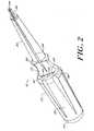
- FIG. 2illustrates the suture anchor insertion tool 12 having an elongate, generally cylindrical handle 22.
- the handle 22has proximal 24 and distal 26 ends and a sidewall 28 disposed there-between.
- the handle 22preferably is textured to allow a surgeon to grasp and manipulate the tool 12.
- the shape and dimensions of the handle 22may be selected by a person of ordinary skill in the art to allow the handle 22 to be suitably grasped and manipulated by a surgeon in a surgical environment.
- An elongate, generally cylindrical suture anchor inserting member 30extends from the distal end 26 of the handle 22, and the inserting member 30 may be integral with the handle.
- the suture anchor inserting member 30has a distal tip 32 that includes a suture anchor seating element 34.
- the suture anchor seating elementmay be in the form of a hexagonal opening.
- the suture anchor installation tool 12may be made from any material useful for constructing surgical tools, the distal tip 32 preferably is made of a durable metal, such as a stainless steel.
- the handle 22includes an internal retaining chamber 20, which is integral with the handle 22.
- the retaining chamber 20has an opening 36 that faces substantially toward the distal end 26 of the handle 22.
- the opening 36has one flat side 38, which is at an interior portion of the handle, and one arcuate side 40, which abuts sidewall 28.
- the height 42 of the opening 36is generally in the range of approximately 3.2 to 12.7 mm (approximately 0.125 to 0.500 inch), and preferably about 7.6 mm (about 0.300 inch).
- the width 44 of the opening 36is generally in the range of approximately 6.35 to 25.4 mm (approximately 0.250 to 1.00 inch), and preferably about 15.2 mm (about 0.600 inch).
- the size and shape of the opening 36, and the chamber 20,should be such that the packet 18 is retained by the force of a friction fit in the partially inserted position shown in FIG: 1.
- the force of the friction fitshould be small enough, however, to allow the packet 18 to be pulled from the chamber 20 by a predetermined tension placed on the suture thread 16, such as the tension that is applied when the suture anchor insertion tool 12 is removed from the surgical site after the suture anchor 14 has been inserted into a bone.
- the retaining chamber 20extends within the handle 22, proximally from the opening 36, to form a cavity that is substantially coaxial with a longitudinal axis 46 of the handle 22.
- the height 48 of the chamber 20generally is in the range of approximately 3.2 to 12.7 mm (approximately 0.125 to 0.500 inch), and preferably about 7.6 mm (about 0.300 inch).
- the length 50 of the chamberis generally in the range of approximately 12.7 to 101.6 mm (approximately 0.500 to 4.00 inches), and preferably about 50.8 mm (about 2.00 inches).
- modifications in the size of packet 18, chamber 20 and opening 36may be made to accommodate insertion tools and/or suture packets of different sizes.
- FIGS. 2 and 3further illustrate that an angled barrier portion 52 is provided on a distal portion of the handle 22.
- the angled barrier portion 52is a flat surface that originates at the flat side 38 of the opening 36 and extends distally to an interface surface 31 of the suture anchor inserting member 30 and the handle 22 at an angle so as to form a partial barrier between the opening 36 and the distal tip 32.
- the angle formed between the barrier portion 52 and the longitudinal axis 46 of the suture anchor insertion toolshould be selected to achieve the desired friction fit between the packet 18 and the handle 22. The steeper the angle, the greater will be the force required to remove the packet 18 from the chamber 20. This angle may be between about 10° and 45°, preferably between about 15° and 20° and most preferably about 17°.
- a slot 54is provided on the suture anchor insertion tool 12.
- the slot 54extends longitudinally from the suture anchor seating element 34 at the distal tip 32 of the suture anchor insertion member 30, through the length of the suture anchor insertion member 30 and into the angled barrier portion 52.
- the slot 54should be of sufficient width and depth to seat two lengths of suture thread 16.
- the slot 54has a width in the range of about 0.6 to 2.5 mm (about 0.025 to 0.100 inch) and a depth in the range of about 2.0 to 10.2 mm (about 0.080 to 0.400 inch).
- the proximal portion 24 of the handle 22may include a removable cap 56. Removal of the cap 56 facilitates access to the interior of the chamber 20 and to the packet 18 retained therein.
- FIG. 3illustrates the relationship between the various parts of the suture anchor insertion system of the invention.
- the suture anchor 14, which in this embodiment is a threaded suture anchor,is disposed on the suture seating element 34 on the distal tip 32 of the suture anchor insertion tool 12.
- An intermediate portion of suture thread 16is attached to the suture anchor 14, leaving two lengths of the suture thread 16 to extend distally through the slot 54.
- the two lengths of the suture thread 16extend into and are stored within the packet 18.
- the packet 18is at least partially disposed within and is retained by the retaining chamber 20 in a frictional fit created by contact of the packet 18 with the chamber opening 36 and the angled barrier portion 52.
- the threaded suture anchor 14, shown attached to the suture anchor installation tool in FIGS. 1 and 3,will now be described with reference to FIGS. 4 and 5.
- the exemplary threaded suture anchor 14is substantially cylindrical and has a proximal end 58, an apex-forming distal end 60 and a sidewall 62 disposed between the proximal 58 and distal 60 ends.
- the distal end 60may be self-tapping, or it may simply form an apex which may be threaded into a bore preformed within a bone.
- the threaded suture anchor 14 used with the system of the inventiongenerally has a major diameter of less than about 2.3 mm (about 0.090 inch). More preferably the major diameter of the anchor 14 is about 2.0 mm (about 0.079 inch).
- the sidewall 62 of the threaded suture anchorhas at least one external thread 64 suitable for retaining the threaded suture anchor within a bone.
- the shape of the proximal-most portion of the threaded suture anchor 14is configured to mate with the suture anchor seating element 34 on the distal tip 32 of the suture anchor inserting tool 12.
- the proximal-most portion of the threaded suture anchor 14, including external threads on this portionis in the form of a hexagon 66.
- the threaded suture anchor 14preferably includes a hole 68 that extends in a direction transverse to the longitudinal axis 63 of the anchor 14.
- the hole 68is useful to seat an intermediate portion of the suture thread 16 when the anchor 14 is operatively attached to the suture anchor insertion tool 12.
- Grooves 70, 72preferably communicate with the hole 68 and extend proximally therefrom. Grooves 70, 72 are useful to seat a length of suture thread, and should be of a sufficient width and depth to seat a length of suture thread while the suture anchor 14 is mated to the suture anchor seating element 34 of the suture anchor inserting tool 12.
- the width of the grooves 70, 72is not otherwise particularly limited, but by way of example can be in the range of about 0.25 to 0.9 mm (about 0.010 to 0.036 inch). Similarly, the grooves 70, 72 can be of virtually any depth as long as they are not so deep as to compromise the structural integrity of the threaded suture anchor 14. Preferably, the width of the anchor material remaining between the opposed grooves should be in the range of about 0.5 to 1.2 mm (about 0.020 to 0.048 inches).
- the suture anchor 14may be retained to the suture anchor retaining element 34 on the distal tip 32 of the suture anchor installation tool 12 by a combination of the mating features of the element 34 and anchor 14, such as the hexagonal shape 66 of the proximal portion of the anchor 14, and tension from the suture thread 16 retained within the hole 68.
- the suture thread 16is retained within the anchor 14, and extends proximally to the packet 18 where the suture thread 16 is stored.
- the packet 18is held in place by a friction fit within the suture anchor insertion tool 12.
- Tension in the suture thread 16can be adjusted by varying the placement of the packet 18 within the tool 12. This tension helps to retain the anchor 14 upon the anchor seating element 34.
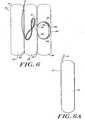
- the packet 18, as shown in FIGS. 6 and 6Aincludes an outer wrapping member 74 which houses the suture thread 16 (which has two free ends 76, 78) and any needles 80, 82 attached thereto.
- the outer wrapping member 74is divided into three portions 84, 86, 88, each of which is separated by creases 90, 92. As shown, the outer wrapping member 74 is laid flat in an "open" position. In use with the suture anchor installation system of the invention, the outer wrapping member 74 is folded along the two crease lines 90, 92 to enclose the suture thread 16 and needles 80, 82. This may be accomplished by folding portion 88 to cover portion 86, then folding portion 84 to cover portions 86 and 88.
- the internal portion of the wrapping member 74may include a structure (not shown) for anchoring the thread and/or needles within the cover.
- the packet 18should be of dimensions suitable to fit snugly within chamber 20, while still being capable of easy removal in response to a predetermined tension placed on the suture thread 16, such as the tension that is applied when the suture anchor insertion tool 12 is removed from the surgical site after the suture anchor 14 has been inserted into a bone.
- the width of the packet 18is generally in the range of approximately 6.4 to 25.4 mm (approximately 0.250 to 1.00 inch), and preferably about 15.2 mm (about 0.600 inch).
- the length of the packet 18is generally in the range of approximately 25.4 to 101.6 mm (approximately 1.00 to 4.00 inches).
- the dimensions of the packet 18may vary depending upon the dimensions of the retaining chamber 20 and the opening 36.
- the dimensions of the outer wrapping member 74should be selected to achieve the appropriate closed packet 18 dimensions as described above.
- each of the three portions 84, 86, 88should have length and width dimensions similar to the dimensions for the closed packet of FIG. 6A as described above.
- the overall width of the outer wrapping member 74may therefore generally be in the range of approximately 6.4 to 25.4 mm (approximately 0.250 to 1.00 inches).
- the length of the outer wrapping member 74may generally be in the range of approximately 25.4 to 101.6 mm (approximately 1.00 to 4.00 inches).
- the outer wrapping member 74may be constructed from among a variety of materials including paper-based material, such as cardboard, plastic and metal.
- a currently preferred material for the outer wrapping member 74is nine point cardboard.
- Alternative packets and packet materialsmay be used with the invention, provided that such alternative packets fit snugly within the chamber 20, are retainable within the chamber 20 by a frictional force, and are removable from the chamber 20 in response to a predetermined tension placed on the suture thread 16.
- Such alternative packetsmay include a packet constructed from a foam material, or a packet constructed from a soft plastic liner material that can be fastened or closed to form a packet.
- suture thread 16may be constructed from a variety of suture materials.
- Exemplary materialsinclude, but are not limited to, braided polyester and polydioxanone (PDS).
- Each suture needle 80, 82has a first tissue penetrating end 94 and a second trailing end 96.
- the size and shape of the needles used with the system of the inventionmay be selected by a person of ordinary skill in the art depending upon the specific application of the system, and in particular, depending upon whether the system is used in an open or closed (e.g. arthroscopic) surgical procedure.
- the needles 80, 82are at least slightly curved.
- a needle holder 98may optionally be provided.
- the needle holder 98includes a length of tubing suitable to hold the penetrating end 94 of each needle 80, 82 within opposite sides of the tubing.
- the packet 18may contain more than one type of needle attached to the suture thread, and may contain more than one suture thread attached to the suture anchor. Inclusion of multiple needles or threads within a packet allows a surgeon the most flexibility to accommodate the challenges of a given surgical procedure.
- FIGS. 7 through 11illustrate an additional embodiment of a suture anchor installation system of the invention.
- FIG. 7illustrates a suture anchor installation system 110 having a suture anchor installation tool 112 and a suture anchor 114 releasably mated to the tool 112.
- the cross-sectional view of FIG. 8illustrates the tool 112 and anchor 114, as well as suture thread 116 attached to the suture anchor 114 and a packet 118 containing additional lengths of the suture thread 116 and any needles attached thereto.
- the packet 118is at least partially housed within the retaining chamber 120 of the suture anchor installation tool 112.
- the suture anchor installation tool 112has an elongate, generally cylindrical handle 122 having proximal 124 and distal ends 126 and a sidewall 128 disposed there-between.
- the shape and dimensions of the handle 122may be selected and varied by a person of ordinary skill in the art to allow the handle 122 to be suitably grasped and manipulated by a surgeon in a surgical environment.
- a hollow, elongate suture anchor inserting member 130extends from, and may be integral with, the distal end 126 of the handle 122.
- the suture anchor inserting memberhas a distal end 132 that includes a suture seating element 134 configured to releasably mate with the suture anchor 114.
- the suture anchor inserting membermay be constructed of a material useful for surgical applications.
- a preferred materialis a biomedically compatible metal such as stainless steel.
- the retaining chamber 120is integral with the handle 122 and may be similar to the chamber 20 described above with respect to FIGS. 1-3.
- the chamber 120has an opening 136 that faces substantially toward the distal end 126 of the handle 122.
- the opening 136has a flat side 135, and arcuate side 137. If the housing is not truly cylindrical, that is, if the housing has a hexagonal or octagonal shape approximating a cylinder, the arcuate shaped side will be similarly angled to approximate an arc.
- the dimensions of the opening 136 and the chamber 120may be similar to those described with respect to FIGS. 1 to 3.
- the height and shape of the opening 136, and the chamber 120should be such that the packet 118 is retained by the force of a friction fit in the partially inserted position shown in FIG. 8.
- the force of the friction fitshould be small enough, however, to allow the packet 118 to be pulled from the chamber 120 by the level of tension placed on the suture thread 116 during the act of disengaging the tool 112 from the suture anchor 114 and removing the tool 112 from the surgical site once the anchor has been inserted into a bone.
- the packet 118may be identical to the packet described above with respect to FIGS. 6 and 6A.
- a suture anchor 114 useful with the system of FIGS. 7 and 8, illustrated in FIG. 9,includes a substantially cylindrical body with a proximal end 138, a distal end 140 forming an apex and a sidewall 142 disposed between the proximal 138 and distal 140 ends.
- the suture anchor 114also has two opposed deformable barbs 144, 146 extending from the sidewall 142.
- the free ends of the deformable barbs 144, 146may extend outwardly from the sidewall 142 and proximally (toward the proximal end 138 of the suture anchor 114) such that each barb defines an angle that is between about 10° and 90° with respect to the sidewall 142. More or fewer deformable barbs may be provided as desired to ensure proper retention of the suture anchor 114 within a bone.
- the suture anchor 114further includes a hole 148 that extends in a direction that is transverse to the longitudinal axis 151 of anchor 114.
- the hole 148is useful to seat and retain an intermediate portion of suture thread 116 during use of the suture anchor insertion system 110.
- Grooves 150which are similar to grooves 70, 72, are also provided on the suture anchor 114. These grooves 150 communicate with the hole 148 and extend proximally therefrom.
- the non-threaded suture anchorWhen non-threaded suture anchors are used with the system of the invention, such as the barbed suture anchor 114, the non-threaded suture anchor generally has a diameter of less than about 1.5 mm (about 0.060 inch). More preferably the diameter of the non-threaded suture anchor is about 1.3 mm (about 0.050 inch).
- the suture anchor seating element 134as shown in the distal view of the suture anchor inserting member 130 in FIG. 9A, consists primarily of the inner bore 155 of the hollow suture anchor inserting member 130 and two opposed openings 152, 154 that help secure the anchor 114 to the inserting member 130.
- the anchor 114is releasably mated to the suture anchor inserting member 130 by seating the barbs 144, 146 in the openings 152, 154.
- the suture seating element 134 of the suture anchor inserting member 130may also include two opposed slots 156, 158. Slots 156, 158 are aligned with the hole 148 in the suture anchor 114. The slots 156, 158 provide clearance, as best shown in FIG. 10, in the suture anchor inserting member 130 for the suture thread 116 to exit from either side of the hole 150 in the suture anchor 114.
- the suture anchor inserting member 130may also include a cut-out portion 160.
- the cut-out portion 160provides access to the interior of the hollow suture anchor inserting member 130, thus allowing the suture anchor 114 to be inserted therein.
- the anchor 114may be placed within the cut-out 160, then advanced toward the distal end 132. This action causes the barbs 144, 146 to deform until they are aligned with the holes 152, 154. Once aligned with holes 152, 154, the deformed barbs 144, 146 spring into the openings 152, 154 to releasably retain the suture anchor 114 within the suture anchor inserting member 130.
- the handle 122preferably includes an actuator 162 that is slidably mounted on the side wall 128 of the handle 122.
- the actuatormay be in the form of a rectangularly-shaped base 164, having a series of flanges 166, with varying heights and angled surfaces, that allow the actuator 162 to be easily manipulated in either of two directions by a surgeon's thumb.
- the actuatormay be manipulated to slide in a direction substantially parallel to the longitudinal axis 168 of the handle 122.
- the actuator 162communicates with an insertion pin 170 that extends from the actuator 162, in the interior of the handle 122, through the interior of the hollow suture anchor inserting member 130 to communicate with the suture anchor 114.
- the operation of the insertion pin 170is described with reference to FIGS. 10 and 11.
- the suture anchor 114which is releasably secured to the distal end 132 of the suture anchor inserting member 130, is aligned with a preformed bore 172 in a bone 174, as illustrated in FIG. 10.
- the insertion pin 170contacts the suture anchor 114 and pushes the suture anchor 114 forward to free the barbs 144, 146 from the holes 152, 154. This action releases the suture anchor 114 from the suture anchor inserting member 130 and installs the suture anchor into the preformed bore 172 in the bone 174 as illustrated in FIG. 11.
- the suture anchor insertion tool 112may be removed. Upon separation of the tool 112 and the anchor 114, and removal of the tool 112 from the patient's body, tension is applied by the suture thread (attached to the installed suture anchor), causing the packet 118 to be released from its frictional fit within the chamber 120. The packet 118 thus becomes separated from the suture anchor installation tool 112, and the suture thread 116 and any needles contained in the packet may be used by a surgeon.
Landscapes
- Health & Medical Sciences (AREA)
- Surgery (AREA)
- Life Sciences & Earth Sciences (AREA)
- Biomedical Technology (AREA)
- Nuclear Medicine, Radiotherapy & Molecular Imaging (AREA)
- Engineering & Computer Science (AREA)
- Rheumatology (AREA)
- Heart & Thoracic Surgery (AREA)
- Medical Informatics (AREA)
- Molecular Biology (AREA)
- Animal Behavior & Ethology (AREA)
- General Health & Medical Sciences (AREA)
- Public Health (AREA)
- Veterinary Medicine (AREA)
- Surgical Instruments (AREA)
Description
Although not necessary, the internal portion of the wrapping
Claims (21)
- A suture anchor insertion system (10), comprising:an elongate handle (22) having a proximal end (24), a distal end (26) and a sidewall (28) disposed between the proximal and distal ends (24, 26);an elongate suture anchor inserting member (30) extending from the distal end (26)of the handle (22) and having a suture anchor seating element (34) at a distal end (32)thereof, the suture seating element being effective to releasably seat a suture anchor (14);anda retaining chamber (20)characterised in that said retaining chamber is integral with and internal to the handle (22), the retainingchamber (20) having an opening (36) facing substantially toward the distal end (26) of thehandle (22).
- A suture anchor installation system (10) comprising:an elongate handle (22) having a proximal end (24), a distal end (26) and a sidewall (28) disposed between the proximal and distal ends (24, 26);a hollow elongate suture anchor inserting member (30) extending from the distalend (26) of the handle (22) and having a suture anchor seating element (34) on a distal end(32) thereof for releasably seating a suture anchor (14); anda retaining chambercharacterised in that said retaining chamber is extending (20) internal to the handle (22) substantiallycoaxially with the handle (22), the chamber (20) having an opening (36) facing the distalend (26) of the handle (22).
- The system (10) of claim 1 or claim 2, further comprising a suture anchor (14),such as a threaded or non-threaded suture anchor, releasably seated in the suture anchorseating element (34).
- The system (10) of claim 3, further comprising a suture thread (16) having two freeends and an intermediate portion, the intermediate portion being attached to a portion ofthe suture anchor (14).
- The system (10) of claim 4, further comprising at least one suture needle attachedto a free end of the suture thread (16).
- The system (10) of claim 5, further comprising a packet (18) disposed at leastpartially within the retaining chamber (20), the packet (18) containing the at least onesuture needle and the two free ends of the suture thread (16).
- The system (10) of claim 6, wherein the packet (18) further includes a selection ofsuture needles and a selection of suture threads (16).
- The system (10) of claim 6 or claim 7, wherein the packet (18) is releasable fromthe chamber (20) when a predetermined-tension is placed on a suture thread (16) from thedirection of the chamber opening (36).
- The system (10) of any one of claims 1 to 8, wherein the retaining chamber (20)extends proximally from the opening (36) to form a cavity within the handle (22) that issubstantially coaxial with a longitudinal axis of the handle (22).
- The system (10) of claim 9, wherein the retaining chamber (20) has a length in therange of 13 to 100mm (0.5 to 4.0 inches).
- The system (10) of claim 9 or claim 10, wherein the retaining chamber (20) has aheight in the range of 3.2 to 13mm (0.125 to 0.500 inches).
- The system (10) of any one of claims 9 to 11, wherein the opening (36) of theretaining chamber (20) is substantially semi-circular in shape and has a height in the rangeof 3.2 to 13mm (0.125 to 0.500 inch) and a width in the range of 6 to 25mm (0.250 to1.000 inch).
- The system (10) of claim 2 or any claim dependent thereon, further comprising:an actuator element (162) slidably mounted on the sidewall (128) of the handle(122); andan insertion pin (170), operatively connected to the actuator element (162) andextending into the suture anchor inserting member (130), the insertion pin (170) being operable by movement of the actuator element (162) to release the suture anchor (114)releasably seated in the suture anchor seating element.
- The system of claim 13, wherein a longitudinal slot (54) extends throughout thelength of the suture insertion member and at least partially, the slot being effective to seatat least two lengths of suture thread (16).
- The system of claim 2 or any claim dependent thereon, wherein the suture anchor(114) is a non-threaded suture anchor comprising a substantially cylindrical anchormember having a proximal end (138) matable with the suture anchor seating element, adistal end (140), a side wall (142) disposed between the proximal and distal ends (138,140) and two opposed barbs (144, 146) extending from the side wall (142), the free end ofeach barb (144, 146) extending away from the anchor member (114) and toward theproximal end (138) of the anchor member (114) such that each barb (144, 146) defines anangle with the sidewall (142) of the anchor member (114) that is between 10° and 90°.
- The system of claim 15, wherein the suture anchor inserting member (130) furthercomprises a pair of openings (152, 154), each being effective to engage one of the twoopposed barbs (144, 146) to releasably retain the suture anchor (114) upon the sutureanchor inserting member (130).
- The system of claim 2 or any claim dependent thereon, wherein the suture anchor isa threaded suture anchor comprising a substantially cylindrical anchor member having aproximal end, a distal end, a side wall disposed between the proximal and distal ends andexternal threads disposed on at least a portion of the sidewall.
- The system of claim 17, wherein the suture seating element is effective toreleasably mount the threaded suture anchor upon the suture anchor inserting element tothread the threaded suture anchor into a bone, and to release the threaded suture anchorfrom the suture anchor inserting element upon exceeding a predetermined tensile force.
- The system of claim 18, wherein an angled barrier portion (52) is provided adjacentto the chamber opening (36) and between the chamber opening (36) and the suture anchorinserting member (30).
- The system of claim 18, wherein a longitudinal slot (54) is provided throughout thelength of the suture insertion member and extending at least partially into the angledbarrier portion, the slot being capable to seat at least one length of suture thread (16).
- The system of claim 14 or claim 20, wherein the suture anchor seating element hasa distal facing end that defines a hexagonal bore.
Applications Claiming Priority (3)
| Application Number | Priority Date | Filing Date | Title |
|---|---|---|---|
| US870856 | 1997-06-06 | ||
| US08/870,856US5814051A (en) | 1997-06-06 | 1997-06-06 | Suture anchor insertion system |
| PCT/US1998/009467WO1998055031A1 (en) | 1997-06-06 | 1998-05-07 | Suture anchor insertion system |
Publications (3)
| Publication Number | Publication Date |
|---|---|
| EP1011475A1 EP1011475A1 (en) | 2000-06-28 |
| EP1011475A4 EP1011475A4 (en) | 2001-02-14 |
| EP1011475B1true EP1011475B1 (en) | 2005-08-17 |
Family
ID=25356199
Family Applications (1)
| Application Number | Title | Priority Date | Filing Date |
|---|---|---|---|
| EP98921077AExpired - LifetimeEP1011475B1 (en) | 1997-06-06 | 1998-05-07 | Suture anchor insertion system |
Country Status (7)
| Country | Link |
|---|---|
| US (1) | US5814051A (en) |
| EP (1) | EP1011475B1 (en) |
| JP (1) | JP2002516585A (en) |
| AU (1) | AU736889B2 (en) |
| CA (1) | CA2293541C (en) |
| DE (1) | DE69831247T2 (en) |
| WO (1) | WO1998055031A1 (en) |
Families Citing this family (116)
| Publication number | Priority date | Publication date | Assignee | Title |
|---|---|---|---|---|
| US8795332B2 (en) | 2002-09-30 | 2014-08-05 | Ethicon, Inc. | Barbed sutures |
| US6241747B1 (en) | 1993-05-03 | 2001-06-05 | Quill Medical, Inc. | Barbed Bodily tissue connector |
| US6013083A (en)* | 1997-05-02 | 2000-01-11 | Bennett; William F. | Arthroscopic rotator cuff repair apparatus and method |
| US5858466A (en)* | 1996-06-24 | 1999-01-12 | Taiwan Semiconductor Manufacturing Company, Ltd. | Photoresist supply system with air venting |
| US6264676B1 (en) | 1996-11-08 | 2001-07-24 | Scimed Life Systems, Inc. | Protective sheath for transvaginal anchor implantation devices |
| US6053935A (en) | 1996-11-08 | 2000-04-25 | Boston Scientific Corporation | Transvaginal anchor implantation device |
| US5931855A (en) | 1997-05-21 | 1999-08-03 | Frank Hoffman | Surgical methods using one-way suture |
| US5944724A (en)* | 1997-10-30 | 1999-08-31 | Mitek Surgical Products, Inc. | Suture anchor insertion system |
| US6096041A (en) | 1998-01-27 | 2000-08-01 | Scimed Life Systems, Inc. | Bone anchors for bone anchor implantation device |
| US5944739A (en)* | 1998-03-12 | 1999-08-31 | Surgical Dynamics, Inc. | Suture anchor installation system |
| US6165203A (en)* | 1998-09-11 | 2000-12-26 | Bio Innovation, Ltd. | Suture anchor installation devices and methods |
| US6146407A (en)* | 1998-09-11 | 2000-11-14 | Bio Innovation, Ltd. | Suture anchor installation devices and methods |
| US8343186B2 (en) | 2004-04-06 | 2013-01-01 | Arthrex, Inc. | Fully threaded suture anchor with transverse anchor pin |
| US7226469B2 (en)* | 1999-02-02 | 2007-06-05 | Arthrex, Inc. | Insert molded suture anchor |
| US9521999B2 (en) | 2005-09-13 | 2016-12-20 | Arthrex, Inc. | Fully-threaded bioabsorbable suture anchor |
| US20060161159A1 (en)* | 1999-02-02 | 2006-07-20 | Dreyfuss Peter J | PEEK ribbed suture anchor |
| US20070225764A1 (en)* | 1999-02-02 | 2007-09-27 | Benavitz William C | Insert molded suture anchor |
| US6306158B1 (en) | 1999-03-02 | 2001-10-23 | Edwin C. Bartlett | Suture anchor and associated method of implantation |
| US8632590B2 (en) | 1999-10-20 | 2014-01-21 | Anulex Technologies, Inc. | Apparatus and methods for the treatment of the intervertebral disc |
| US7004970B2 (en) | 1999-10-20 | 2006-02-28 | Anulex Technologies, Inc. | Methods and devices for spinal disc annulus reconstruction and repair |
| US8128698B2 (en) | 1999-10-20 | 2012-03-06 | Anulex Technologies, Inc. | Method and apparatus for the treatment of the intervertebral disc annulus |
| US7615076B2 (en) | 1999-10-20 | 2009-11-10 | Anulex Technologies, Inc. | Method and apparatus for the treatment of the intervertebral disc annulus |
| US6641596B1 (en) | 2000-10-18 | 2003-11-04 | Ethicon, Inc. | Knotless bioabsorbable suture anchor system and method |
| US6527795B1 (en)* | 2000-10-18 | 2003-03-04 | Ethicon, Inc. | Knotless suture anchor system and method of use |
| US6887259B2 (en)* | 2000-10-18 | 2005-05-03 | Depuy Mitek, Inc. | Suture anchor system and method of use |
| US6602260B2 (en)* | 2001-02-02 | 2003-08-05 | Ams Research Corporation | Powered bone screw device |
| JP4181410B2 (en) | 2001-03-09 | 2008-11-12 | ボストン サイエンティフィック リミテッド | System and method for implanting an implant |
| US8033983B2 (en) | 2001-03-09 | 2011-10-11 | Boston Scientific Scimed, Inc. | Medical implant |
| DE60223502T2 (en) | 2001-03-09 | 2008-11-13 | Boston Scientific Ltd., St. Michael | MEDICAL SLING |
| US20030125750A1 (en)* | 2001-11-05 | 2003-07-03 | Zwirnmann Ralph Fritz | Spring loaded fixation element insertion device |
| US7147641B2 (en) | 2001-05-30 | 2006-12-12 | Chen Michael C | Fixation element insertion device |
| US7056331B2 (en) | 2001-06-29 | 2006-06-06 | Quill Medical, Inc. | Suture method |
| US6848152B2 (en) | 2001-08-31 | 2005-02-01 | Quill Medical, Inc. | Method of forming barbs on a suture and apparatus for performing same |
| US6986781B2 (en) | 2001-11-08 | 2006-01-17 | Smith & Nephew, Inc. | Tissue repair system |
| US7867251B2 (en) | 2001-11-08 | 2011-01-11 | Smith & Nephew, Inc. | Reattachment of tissue to base tissue |
| US6843799B2 (en) | 2002-03-25 | 2005-01-18 | Edwin C. Bartlett | Suture anchor system and associated method |
| US20030204193A1 (en)* | 2002-04-25 | 2003-10-30 | Stefan Gabriel | Suture anchor insertion tool |
| US7131973B2 (en) | 2002-05-16 | 2006-11-07 | Boston Scientific Scimed, Inc. | Bone anchor implantation device |
| US6773450B2 (en) | 2002-08-09 | 2004-08-10 | Quill Medical, Inc. | Suture anchor and method |
| US20040088003A1 (en) | 2002-09-30 | 2004-05-06 | Leung Jeffrey C. | Barbed suture in combination with surgical needle |
| US8100940B2 (en) | 2002-09-30 | 2012-01-24 | Quill Medical, Inc. | Barb configurations for barbed sutures |
| AU2003259834A1 (en) | 2002-12-17 | 2004-07-29 | Boston Scientific Limited | Spacer for sling delivery system |
| US7624487B2 (en) | 2003-05-13 | 2009-12-01 | Quill Medical, Inc. | Apparatus and method for forming barbs on a suture |
| US8267981B2 (en)* | 2003-06-10 | 2012-09-18 | Depuy Mitek, Inc. | Suture anchor with improved drive head |
| US7361138B2 (en) | 2003-07-31 | 2008-04-22 | Scimed Life Systems, Inc. | Bioabsorbable casing for surgical sling assembly |
| US7357810B2 (en) | 2003-12-18 | 2008-04-15 | Ethicon, Inc. | High strength suture with absorbable core and suture anchor combination |
| US7329271B2 (en) | 2003-12-18 | 2008-02-12 | Ethicon, Inc. | High strength suture with absorbable core |
| US7645293B2 (en) | 2004-04-21 | 2010-01-12 | United States Surgical Corporation | Suture anchor installation system and method |
| US10548592B2 (en) | 2004-05-14 | 2020-02-04 | Ethicon, Inc. | Suture methods and devices |
| US20060074422A1 (en)* | 2004-09-27 | 2006-04-06 | Story Brooks J | Suture anchor and void filler combination |
| US7947047B2 (en)* | 2005-06-20 | 2011-05-24 | Ams Research Corporation | Medical screwdrivers and methods |
| EP1762186B1 (en) | 2005-09-12 | 2011-02-16 | Arthrex, Inc. | Suture anchor with eyelet |
| US20070219557A1 (en)* | 2006-03-17 | 2007-09-20 | Bourque Bernard J | Soft tissue fixation |
| US20080109037A1 (en)* | 2006-11-03 | 2008-05-08 | Musculoskeletal Transplant Foundation | Press fit suture anchor and inserter assembly |
| US11660190B2 (en) | 2007-03-13 | 2023-05-30 | Edwards Lifesciences Corporation | Tissue anchors, systems and methods, and devices |
| US8915943B2 (en) | 2007-04-13 | 2014-12-23 | Ethicon, Inc. | Self-retaining systems for surgical procedures |
| ES2398779T3 (en) | 2007-09-27 | 2013-03-21 | Ethicon Llc | Self-retaining sutures that include tissue retention elements with enhanced strength |
| EP2211779B1 (en)* | 2007-10-15 | 2014-08-20 | Edwards Lifesciences Corporation | Transcatheter heart valve with micro-anchors |
| WO2009086172A2 (en) | 2007-12-19 | 2009-07-09 | Angiotech Pharmaceuticals, Inc. | Self-retaining sutures with heat-contact mediated retainers |
| US8916077B1 (en) | 2007-12-19 | 2014-12-23 | Ethicon, Inc. | Self-retaining sutures with retainers formed from molten material |
| US8118834B1 (en) | 2007-12-20 | 2012-02-21 | Angiotech Pharmaceuticals, Inc. | Composite self-retaining sutures and method |
| US8875607B2 (en) | 2008-01-30 | 2014-11-04 | Ethicon, Inc. | Apparatus and method for forming self-retaining sutures |
| US8615856B1 (en) | 2008-01-30 | 2013-12-31 | Ethicon, Inc. | Apparatus and method for forming self-retaining sutures |
| ES2706295T3 (en) | 2008-02-21 | 2019-03-28 | Ethicon Llc | Method and apparatus for raising retainers in self-retaining sutures |
| US8216273B1 (en) | 2008-02-25 | 2012-07-10 | Ethicon, Inc. | Self-retainers with supporting structures on a suture |
| US8641732B1 (en) | 2008-02-26 | 2014-02-04 | Ethicon, Inc. | Self-retaining suture with variable dimension filament and method |
| US9131939B1 (en)* | 2008-02-27 | 2015-09-15 | Mitralign, Inc. | Device for percutaneously delivering a cardiac implant through the application of direct actuation forces external to the body |
| US20100228270A1 (en)* | 2008-04-11 | 2010-09-09 | Michael Bogart | Deployment System for Surgical Suture |
| US8864776B2 (en) | 2008-04-11 | 2014-10-21 | Covidien Lp | Deployment system for surgical suture |
| SG188784A1 (en) | 2008-04-15 | 2013-04-30 | Ethicon Llc | Self-retaining sutures with bi-directional retainers or uni-directional retainers |
| US8961560B2 (en) | 2008-05-16 | 2015-02-24 | Ethicon, Inc. | Bidirectional self-retaining sutures with laser-marked and/or non-laser marked indicia and methods |
| US8888796B2 (en)* | 2008-06-07 | 2014-11-18 | Ethicon, Inc. | Devices for tensioning barbed sutures and methods therefor |
| US8974494B2 (en)* | 2008-07-17 | 2015-03-10 | Smith & Nephew, Inc. | Surgical devices |
| US9050077B2 (en)* | 2008-09-18 | 2015-06-09 | Smith & Nephew, Inc. | Suture anchor inserter |
| US8163022B2 (en) | 2008-10-14 | 2012-04-24 | Anulex Technologies, Inc. | Method and apparatus for the treatment of the intervertebral disc annulus |
| US20100121355A1 (en) | 2008-10-24 | 2010-05-13 | The Foundry, Llc | Methods and devices for suture anchor delivery |
| EP2352440B1 (en) | 2008-11-03 | 2019-02-20 | Ethicon LLC | Length of self-retaining suture and device for using the same |
| WO2010132310A1 (en) | 2009-05-12 | 2010-11-18 | Foundry Newco Xi, Inc. | Methods and devices to treat diseased or injured musculoskeletal tissue |
| US20100292733A1 (en) | 2009-05-12 | 2010-11-18 | Foundry Newco Xi, Inc. | Knotless suture anchor and methods of use |
| US20110106013A1 (en)* | 2009-10-30 | 2011-05-05 | DePuy Mikek, Inc. | Dual cannula system and method for partial thickness rotator cuff repair |
| US8672967B2 (en)* | 2009-10-30 | 2014-03-18 | Depuy Mitek, Llc | Partial thickness rotator cuff repair system and method |
| DE102009052394A1 (en) | 2009-11-10 | 2011-05-26 | Universität Rostock | Suture anchor system |
| US8652153B2 (en) | 2010-01-11 | 2014-02-18 | Anulex Technologies, Inc. | Intervertebral disc annulus repair system and bone anchor delivery tool |
| US10743854B2 (en) | 2010-01-20 | 2020-08-18 | Micro Interventional Devices, Inc. | Tissue closure device and method |
| US10959840B2 (en) | 2010-01-20 | 2021-03-30 | Micro Interventional Devices, Inc. | Systems and methods for affixing a prosthesis to tissue |
| US9980708B2 (en)* | 2010-01-20 | 2018-05-29 | Micro Interventional Devices, Inc. | Tissue closure device and method |
| US10058314B2 (en) | 2010-01-20 | 2018-08-28 | Micro Interventional Devices, Inc. | Tissue closure device and method |
| US20110178537A1 (en) | 2010-01-20 | 2011-07-21 | Whitman Michael P | Tissue repair implant and delivery device and method |
| NZ626274A (en) | 2010-05-04 | 2015-03-27 | Ethicon Llc | Laser cutting system and methods for creating self-retaining sutures |
| EP3155978B1 (en) | 2010-06-11 | 2022-04-13 | Cilag GmbH International | Suture delivery tools for endoscopic and robot-assisted surgery |
| US8469998B2 (en) | 2010-08-30 | 2013-06-25 | Depuy Mitek, Llc | Knotless suture anchor |
| US8460340B2 (en) | 2010-08-30 | 2013-06-11 | Depuy Mitek, Llc | Knotless suture anchor |
| US8435264B2 (en) | 2010-08-30 | 2013-05-07 | Depuy Mitek, Llc | Knotless suture anchor and driver |
| US11007296B2 (en) | 2010-11-03 | 2021-05-18 | Ethicon, Inc. | Drug-eluting self-retaining sutures and methods relating thereto |
| JP6013352B2 (en) | 2010-11-09 | 2016-10-25 | エシコン・エルエルシーEthicon LLC | Emergency indwelling suture and package |
| US9138219B2 (en) | 2010-12-29 | 2015-09-22 | Tarsus Medical Inc. | Methods and devices for treating a syndesmosis injury |
| KR101132841B1 (en) | 2011-03-07 | 2012-04-02 | 김영재 | A suture |
| CN103889340B (en) | 2011-03-23 | 2018-09-28 | 伊西康有限责任公司 | Self-retaining variable loop suture |
| US20130172931A1 (en) | 2011-06-06 | 2013-07-04 | Jeffrey M. Gross | Methods and devices for soft palate tissue elevation procedures |
| US9131936B2 (en) | 2011-06-10 | 2015-09-15 | Ethicon, Inc. | Anchor tip orientation device and method |
| KR101185583B1 (en) | 2011-12-27 | 2012-09-24 | 김영재 | A suture which need not be knotted and a kit comprising the suture |
| US10010317B2 (en) | 2012-12-05 | 2018-07-03 | Young Jae Kim | Method of improving elasticity of tissue of living body |
| US10178990B2 (en) | 2012-12-05 | 2019-01-15 | Y. Jacobs Medical Inc. | Apparatus for inserting surgical thread, and surgical procedure kit for inserting surgical thread comprising same |
| US10179012B2 (en) | 2013-01-28 | 2019-01-15 | Cartiva, Inc. | Systems and methods for orthopedic repair |
| US9737294B2 (en) | 2013-01-28 | 2017-08-22 | Cartiva, Inc. | Method and system for orthopedic repair |
| SG11201507297QA (en)* | 2013-03-12 | 2015-10-29 | Ziptek Llc | Apparatus and method for securing tissue |
| US9538999B2 (en)* | 2013-03-13 | 2017-01-10 | Medos International Sàrl | Suture storage devices, systems, and methods |
| US10070857B2 (en) | 2013-08-31 | 2018-09-11 | Mitralign, Inc. | Devices and methods for locating and implanting tissue anchors at mitral valve commissure |
| JP6296332B2 (en)* | 2013-11-22 | 2018-03-20 | オリンパステルモバイオマテリアル株式会社 | Anchor fastener |
| WO2015083864A1 (en) | 2013-12-06 | 2015-06-11 | 주식회사 와이제이콥스메디칼 | Apparatus for inserting medical tube and surgical procedure kit for inserting medical tube, having same |
| USD819432S1 (en) | 2014-03-11 | 2018-06-05 | Ziptek LLC. | Screw |
| JP6433673B2 (en)* | 2014-04-02 | 2018-12-05 | オリンパステルモバイオマテリアル株式会社 | Anchor fastener and fastening unit |
| EP3383281B1 (en) | 2015-12-04 | 2024-01-24 | Crossroads Extremity Systems, LLC | Devices for anchoring tissue |
| US10238444B2 (en) | 2016-05-10 | 2019-03-26 | DePuy Synthes Products, Inc. | Insertion tool for flip anchor cable system insertion |
| US12207812B2 (en) | 2016-05-18 | 2025-01-28 | Orthonoble Inc. | Disposable instrument nosepieces for repairing soft tissue to bone coupling |
| US11395687B2 (en) | 2019-03-01 | 2022-07-26 | DePuy Synthes Products, Inc. | Insertion tool for flip anchor cable system insertion |
Family Cites Families (15)
| Publication number | Priority date | Publication date | Assignee | Title |
|---|---|---|---|---|
| US4946468A (en)* | 1989-06-06 | 1990-08-07 | Mitek Surgical Products, Inc. | Suture anchor and suture anchor installation tool |
| US5002550A (en)* | 1989-06-06 | 1991-03-26 | Mitek Surgical Products, Inc. | Suture anchor installation tool |
| US5041129A (en)* | 1990-07-02 | 1991-08-20 | Acufex Microsurgical, Inc. | Slotted suture anchor and method of anchoring a suture |
| US5100417A (en)* | 1990-07-13 | 1992-03-31 | American Cyanamid Company | Suture anchor and driver assembly |
| US5258016A (en)* | 1990-07-13 | 1993-11-02 | American Cyanamid Company | Suture anchor and driver assembly |
| US5078730A (en)* | 1990-11-06 | 1992-01-07 | Mitek Surgical Products, Inc. | Holder for suture anchor assembly |
| US5071420A (en)* | 1991-04-25 | 1991-12-10 | Depuy Du Pont Orthopaedics | Isometry testing device |
| US5174087A (en)* | 1992-02-19 | 1992-12-29 | Mitek Surgical Products, Inc. | Suture anchor assembly packaging system |
| US5522844A (en)* | 1993-06-22 | 1996-06-04 | Johnson; Lanny L. | Suture anchor, suture anchor installation device and method for attaching a suture to a bone |
| US5578057A (en)* | 1993-07-28 | 1996-11-26 | Mitek Surgical Products, Inc. | Anchoring device installation tool assembly and method |
| US5466243A (en)* | 1994-02-17 | 1995-11-14 | Arthrex, Inc. | Method and apparatus for installing a suture anchor through a hollow cannulated grasper |
| US5411506A (en)* | 1994-04-11 | 1995-05-02 | Mitek Surgical Products, Inc. | Anchor driver |
| US5522845A (en)* | 1994-09-27 | 1996-06-04 | Mitek Surgical Products, Inc. | Bone anchor and bone anchor installation |
| US5584860A (en)* | 1995-02-15 | 1996-12-17 | Mitek Surgical Products, Inc. | Suture anchor loader and driver |
| FR2739016B1 (en)* | 1995-09-22 | 1998-02-06 | Comte Georges | DEVICE FOR ANCHORING A SUTURE THREAD IN A PORTION OF BONES IN PARTICULAR |
- 1997
- 1997-06-06USUS08/870,856patent/US5814051A/ennot_activeExpired - Lifetime
- 1998
- 1998-05-07JPJP50243799Apatent/JP2002516585A/enactivePending
- 1998-05-07DEDE69831247Tpatent/DE69831247T2/ennot_activeExpired - Lifetime
- 1998-05-07EPEP98921077Apatent/EP1011475B1/ennot_activeExpired - Lifetime
- 1998-05-07WOPCT/US1998/009467patent/WO1998055031A1/enactiveIP Right Grant
- 1998-05-07CACA002293541Apatent/CA2293541C/ennot_activeExpired - Fee Related
- 1998-05-07AUAU73762/98Apatent/AU736889B2/ennot_activeCeased
Also Published As
| Publication number | Publication date |
|---|---|
| DE69831247T2 (en) | 2006-06-01 |
| AU736889B2 (en) | 2001-08-02 |
| JP2002516585A (en) | 2002-06-04 |
| EP1011475A1 (en) | 2000-06-28 |
| US5814051A (en) | 1998-09-29 |
| CA2293541C (en) | 2004-10-05 |
| DE69831247D1 (en) | 2005-09-22 |
| AU7376298A (en) | 1998-12-21 |
| CA2293541A1 (en) | 1998-12-10 |
| EP1011475A4 (en) | 2001-02-14 |
| WO1998055031A1 (en) | 1998-12-10 |
Similar Documents
| Publication | Publication Date | Title |
|---|---|---|
| EP1011475B1 (en) | Suture anchor insertion system | |
| US5944724A (en) | Suture anchor insertion system | |
| US5207679A (en) | Suture anchor and installation tool | |
| US5814070A (en) | Suture anchor and driver | |
| AU721930B2 (en) | System for anchoring tissue to bone | |
| CA2217406C (en) | Suture anchor installation system with disposable loading unit | |
| AU719350B2 (en) | Suture anchor assembly and methods | |
| EP0955905B1 (en) | Surgical fastening system | |
| JP5355840B2 (en) | Suture loop fastener | |
| EP0558993B1 (en) | Suture anchor and installation tool | |
| EP1836971B1 (en) | Surgical fastener and instrument | |
| US6022373A (en) | Surgical anchor and package and cartridge for surgical anchor | |
| EP2665427B1 (en) | Devices for anchoring suture in bone | |
| WO1999004699A1 (en) | Device and method for delivering a connector for surgically joining and securing flexible tissue repair members | |
| AU2003222662A1 (en) | Suture anchor insertion tool | |
| US8080035B2 (en) | Suture attachment device | |
| CA2523111C (en) | Suture anchor installation system with disposable loading unit | |
| MXPA97001277A (en) | Sutura and actua anchor |
Legal Events
| Date | Code | Title | Description |
|---|---|---|---|
| PUAI | Public reference made under article 153(3) epc to a published international application that has entered the european phase | Free format text:ORIGINAL CODE: 0009012 | |
| 17P | Request for examination filed | Effective date:19991223 | |
| AK | Designated contracting states | Kind code of ref document:A1 Designated state(s):DE FR GB IT | |
| A4 | Supplementary search report drawn up and despatched | Effective date:20010103 | |
| AK | Designated contracting states | Kind code of ref document:A4 Designated state(s):DE FR GB IT | |
| 17Q | First examination report despatched | Effective date:20040319 | |
| GRAP | Despatch of communication of intention to grant a patent | Free format text:ORIGINAL CODE: EPIDOSNIGR1 | |
| GRAS | Grant fee paid | Free format text:ORIGINAL CODE: EPIDOSNIGR3 | |
| GRAA | (expected) grant | Free format text:ORIGINAL CODE: 0009210 | |
| AK | Designated contracting states | Kind code of ref document:B1 Designated state(s):DE FR GB IT | |
| REG | Reference to a national code | Ref country code:GB Ref legal event code:FG4D | |
| REF | Corresponds to: | Ref document number:69831247 Country of ref document:DE Date of ref document:20050922 Kind code of ref document:P | |
| ET | Fr: translation filed | ||
| PLBE | No opposition filed within time limit | Free format text:ORIGINAL CODE: 0009261 | |
| STAA | Information on the status of an ep patent application or granted ep patent | Free format text:STATUS: NO OPPOSITION FILED WITHIN TIME LIMIT | |
| 26N | No opposition filed | Effective date:20060518 | |
| REG | Reference to a national code | Ref country code:FR Ref legal event code:PLFP Year of fee payment:18 | |
| PGFP | Annual fee paid to national office [announced via postgrant information from national office to epo] | Ref country code:GB Payment date:20150506 Year of fee payment:18 Ref country code:DE Payment date:20150428 Year of fee payment:18 | |
| PGFP | Annual fee paid to national office [announced via postgrant information from national office to epo] | Ref country code:IT Payment date:20150515 Year of fee payment:18 Ref country code:FR Payment date:20150508 Year of fee payment:18 | |
| REG | Reference to a national code | Ref country code:DE Ref legal event code:R119 Ref document number:69831247 Country of ref document:DE | |
| GBPC | Gb: european patent ceased through non-payment of renewal fee | Effective date:20160507 | |
| PG25 | Lapsed in a contracting state [announced via postgrant information from national office to epo] | Ref country code:IT Free format text:LAPSE BECAUSE OF NON-PAYMENT OF DUE FEES Effective date:20160507 | |
| REG | Reference to a national code | Ref country code:FR Ref legal event code:ST Effective date:20170131 | |
| PG25 | Lapsed in a contracting state [announced via postgrant information from national office to epo] | Ref country code:FR Free format text:LAPSE BECAUSE OF NON-PAYMENT OF DUE FEES Effective date:20160531 Ref country code:DE Free format text:LAPSE BECAUSE OF NON-PAYMENT OF DUE FEES Effective date:20161201 | |
| PG25 | Lapsed in a contracting state [announced via postgrant information from national office to epo] | Ref country code:GB Free format text:LAPSE BECAUSE OF NON-PAYMENT OF DUE FEES Effective date:20160507 |