EP1011455B1 - Incisional breast biopsy device - Google Patents
Incisional breast biopsy deviceDownload PDFInfo
- Publication number
- EP1011455B1 EP1011455B1EP98946807AEP98946807AEP1011455B1EP 1011455 B1EP1011455 B1EP 1011455B1EP 98946807 AEP98946807 AEP 98946807AEP 98946807 AEP98946807 AEP 98946807AEP 1011455 B1EP1011455 B1EP 1011455B1
- Authority
- EP
- European Patent Office
- Prior art keywords
- cannula
- trigger
- garrote
- guide wire
- tissue
- Prior art date
- Legal status (The legal status is an assumption and is not a legal conclusion. Google has not performed a legal analysis and makes no representation as to the accuracy of the status listed.)
- Expired - Lifetime
Links
- 210000000481breastAnatomy0.000titleclaimsdescription24
- 238000001574biopsyMethods0.000titledescription24
- 230000004807localizationEffects0.000claimsdescription28
- 230000033001locomotionEffects0.000claimsdescription10
- 230000002028prematureEffects0.000claimsdescription3
- 230000003902lesionEffects0.000description14
- 206010006187Breast cancerDiseases0.000description3
- 208000026310Breast neoplasmDiseases0.000description3
- 238000009607mammographyMethods0.000description3
- 238000000034methodMethods0.000description3
- 238000013399early diagnosisMethods0.000description2
- 238000010562histological examinationMethods0.000description2
- 208000014674injuryDiseases0.000description2
- 230000003211malignant effectEffects0.000description2
- 230000008733traumaEffects0.000description2
- 230000005856abnormalityEffects0.000description1
- 230000004913activationEffects0.000description1
- 239000011324beadSubstances0.000description1
- 230000008602contractionEffects0.000description1
- 238000004806packaging method and processMethods0.000description1
- 230000037361pathwayEffects0.000description1
- 230000000149penetrating effectEffects0.000description1
- 238000005381potential energyMethods0.000description1
Images


Classifications
- A—HUMAN NECESSITIES
- A61—MEDICAL OR VETERINARY SCIENCE; HYGIENE
- A61B—DIAGNOSIS; SURGERY; IDENTIFICATION
- A61B10/00—Instruments for taking body samples for diagnostic purposes; Other methods or instruments for diagnosis, e.g. for vaccination diagnosis, sex determination or ovulation-period determination; Throat striking implements
- A61B10/02—Instruments for taking cell samples or for biopsy
- A61B10/0233—Pointed or sharp biopsy instruments
- A61B10/0266—Pointed or sharp biopsy instruments means for severing sample
Definitions
- This inventionrelates generally to surgical instruments and, more particularly, to a device for percutaneous incisional breast biopsy.
- the early diagnosis of breast cancer through the use of mammographyis very important for reducing the morbidity associated with breast cancer. Early diagnosis enables a physician to treat the breast cancer at a more manageable stage of development.
- Mammographyis capable of detecting very small abnormalities in breast tissue.
- mammographyusually cannot differentiate between malignant and benign lesions in the breast. Definitive determination of the status of a lesion often requires a histological examination of the suspect tissue.
- One method for obtaining a tissue sample for histological examinationis through a biopsy or part or all of the suspect tissue.
- devices and methods for performing a biopsy of the breastGenerally, the procedure requires first placing a localization needle within or near the lesion. A guide wire contained within the localization needle is then deployed. The guide wire usually includes hooks that anchor one end of the guide wire in breast tissue near the lesion. Then a biopsy device that includes a cannula and a stylet that is located within the cannula is inserted over the localization needle and guide wire. The device is inserted through a small incision in the breast tissue near the entry point of the localization needle. The stylet bluntly separates breast tissue as the device is inserted down the guide wire toward the lesion.
- Advancement of the deviceis stopped once the tip of the stylet is within or near the lesion. Then, the cannula, which has a cutting surface at its leading edge, is advanced over the stylet and into the tissue thereby cutting a core of tissue. The cutting surface is advanced to a point beyond the end of the guide wire. Then, a second cutting surface, typically a wire garrotte, is activated to perform a cut transverse to the direction the cannula and beyond the end of the guide wire. This second cut releases a plug from the lesion. Then the needle, guide wire, and device are retracted from the breast with the plug. The plug is then histologically examined to determine whether the suspect tissue is malignant or benign.
- a second cutting surfacetypically a wire garrotte
- the current deviceshave a number of disadvantages including: the device, localization needle, and guide wire are not manufactured as a single unit; and the devices generally do not have a means for insuring that the garrote wire is located past the end of the guide wire prior to deployment of the garrote. In order to determine whether the garrote is located past the end of the guidewire, a radiographic check is required. Further, the blunt stylet requires substantial force to insert and may cause trauma to the healthy tissue as it passes to the biopsy site.
- EP-A-0761170relates to apparatus for removing tissue which includes an elongated body defining an opening at a distal end and forming a tissue receiving cavity in communication with the opening, a blunt obturatory at least partially disposed in the tissue receiving cavity, and a cutting member operatively moveable transverse to the elongated body in proximity to the opening.
- US-A-5,353,804relates to an apparatus for removing suspect breast tissue which includes a penetrating member in the form of a stylet with a tapered front end that can be guided along a localisation guide wire.
- the apparatusincludes a first cutting device in the form of a cannula slidingly engaged with the stylet.
- a driving assemblyis in driving engagement with the cannula and, upon activation, potential energy stored in the driving assembly acts to drive the forward end of the cannula forward of the stylet's forward end so as to define a core cavity.
- a second cutting devicewhich includes a garrote wire having a looped section positioned within a recess at the forward end of the cannula is also provided.
- the driving assemblypreferably also acts to rotate the cannula with a cam arrangement such that the cannula rotates when being driven forward.
- the garrote wireis also attached to the rotating cannula such that the wire is drawn up to a stop bead just at the time the cannula reaches its maximum forward extension and further rotation of the cannula results in the contraction of the wire loop and a cutting of a core sample or suspect breast tissue.
- a locating needlehaving a guide wire mounted within it.
- a biopsy devicemanufactured as a unit with a localization needle and a guide wire. Additionally, it is desirable to provide a biopsy device having features to insure that the garrote wire is not deployed until it is past the end of the guide wire. It is also desirable to provide a stylet with cutting members to transect and separate breast tissue and minimize the damage to healthy tissue.
- the present inventionovercomes the problem with previous biopsy devices by providing a biopsy device which is manufactured with an integral localization needle and guide wire.
- the inventionincludes means for insuring that the garrote wire is not deployed until the garrote wire is beyond the end of the guide wire.
- the styletis provided with a blade with transects tissue as the device is inserted to the biopsy site.
- a device for removing suspect breast tissuecomprising:
- the deviceincludes a cannula having a shaft with a cutting surface on one end of the shaft and the other end of the shaft in engagement with a drive assembly. Adjacent to the cutting surface of the cannula is a second cutting mechanism for making a cut transverse to the cut made by the cannula cutting surface.
- Located within the cannula shaftis a stylet.
- the stylethas a tip portion with a blade for transecting and separating tissue and a central chamber for permitting a localization needle to pass through the length of the stylet.
- the localization needlehas an interior chamber permitting passage of a guide wire through the length of the localization needle.
- the devicealso includes a lock feature for preventing deployment of the second cutting mechanism until it is past the end of the guide wire.
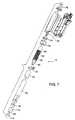
- FIG. 1a biopsy device is shown generally at 10.
- the device 10includes an exterior housing 12 having a trigger slot 14 and a window 16.
- a trigger 18extends through the trigger slot 14.
- a stylet retractor handle 20is mounted adjacent a rear end of the exterior housing 12.
- a localization needle 22is received within the retractor handle 20.
- a hub 24is mounted on a distal end of the localization needle 22.
- a guide wire 26is slidably received within the localization needle 22.
- a stop 28is mounted on one end of the guide wire 26.
- a cannula 30extends from a front portion of the exterior housing 12.
- the cannula 30comprises a shaft 32 and a nosepiece 34.
- a stylet 36having a diameter less than the diameter of the shaft 32 extends beyond the nosepiece 34 of the cannula 30.
- a blade 38is mounted within the stylet 36 for transecting and separating tissue as the device is inserted to the biopsy site.
- the biopsy device 10is inserted by inserting the localization needle 22 into the tissue and deploying the guidewire 26 within the localization needle to anchor the device in the breast tissue.
- the cannula 30 and stylet 36are then advanced over the localization needle with the stylet transecting and separating the healthy breast tissue with minimal trauma to the healthy tissue as the cannula is inserted toward the lesion.
- the cannula 30is then advanced to cut a core of tissue.
- a garrote having a looped section of wireis provided within a recess in the forward end of the cannula.
- the trigger 18is used to activate the garrote and cut the tissue plug in a direction transverse to the direction in which the cannula 30 was advanced.
- the trigger 18is provided with a locking mechanism, as will be described below, for preventing deployment of the garrote prior to movement of a cutting plane of the garrote past an end of the guidewire 26.
- the device 10is shown mounted on an instrument holder 40.
- the instrument holder 40includes a housing 42 and an adjustment knob 44 mounted within the housing 42.
- a bracket 46connects the housing 42 to a track 48.
- the track 48can be fixed at a point along a rail (not shown) by a friction cam brake (not shown).
- a safety wrapper 50is shown adjacent an end of the guide wire 26.
- the safety wrapper 50is removable prior to deployment of the guide wire 26 and serves to prevent premature deployment of the guide wire 26.
- the function of the safety wrapper 50may also be incorporated in the packaging for the device to prevent premature deployment during transport.
- FIG. 3a top view of the device 10 with a portion of the exterior housing 12 removed is shown.
- a drive assembly 52is mounted within the exterior housing 12.
- the drive assembly 52includes a spline 54 having a cylindrical member 56 and a gear member 58 separated by a shoulder 60.
- a connector 62engages the spline 54 with the shaft 32 of the cannula 30.
- a sleeve 64is mounted on the cylindrical member 56.
- a screw base 66is mounted within the exterior housing 12.
- a lead screw 68is mounted to the screw base 66 and extends into the spline 54.
- a finger sleeve 70is mounted within the exterior housing 12 and encircles the gear member 58.
- a finger 72is attached to the finger sleeve 70.
- a gear drive 74is mounted below the geared member 58 and engages the geared member 58.
- a collar 76encircles the spline 54 and is mounted within the exterior housing 12.
- FIG. 4an enlarged view of the drive assembly 52 is shown.
- a threaded member 78extends from a rear portion of the lead screw 68. The threaded member 78 threads into the screw base 66 (not shown).
- a connector shaft 80extends from the front of the geared member 58.
- a central passage 82extends through the connector shaft 80, spline 54, lead screw 68, and the threaded member 78. The central passage 82 accommodates the localization needle 22 (not shown).
- the connector shaft 80includes several slots 84 for receiving the fasteners 77 of the connector 62.
- FIGS. 5A-5Cthe trigger 18 is shown in the three stages of fully locked, partially unlocked, and fully unlocked, respectively.
- the trigger 18is shown in the fully locked position.
- a V-shaped bend 86 in the finger 72is positioned adjacent a ramped portion 88 of a trigger bracket 90.
- a stop 92 formed in the exterior housing 12prevents the trigger 18 from moving in the direction of arrow 94 toward the cannula 30 (not shown).
- the trigger 18is shown in the partially unlocked position.
- Rotation of the adjustment knob 44(not shown) rotates the drive gear 74 which in turn rotates the gear member 58.
- Rotation of the gear member 58causes movement of the spline 54 along the length of the lead screw 68.
- the shoulder 60advances sufficiently to contact the finger sleeve 70.
- additional forward movement of the spline 54pulls the finger sleeve 70 and the attached finger 52 forward.
- Advancement of the finger 72causes the V-shaped bend 86 to ride up the ramped portion 88 of the trigger bracket 90.
- the movement of the V-shaped bend 86pushes the trigger 18 outwardly in the direction of arrow 96.
- the trigger 18is shown in the fully unlocked position.
- the shoulder 60continues to advance the finger sleeve 70 and the finger 72.
- the V-shaped bend 86moves off the ramped portion 88 and onto a flat portion 98 of the trigger bracket 90 the trigger bracket 90 is moved outside of the stop 92 and the trigger 18 can be freely advanced in the direction of arrow 100.
- FIG. 6a partial side view of the trigger mechanism of the device is shown. Specifically, the routing pathway of a return cable 102 is shown. Each end of the return cable 102 is split into a pair of tails 104. One end of the return cable 102 is connected by a pair of stops 106 to an upper portion of the collar 76. The return cable 102 is routed through one of a pair of diametrically opposed holes 108 in the screw base 66 and around a cable post 10. The return cable 102 passes from the cable post 110 to the trigger bracket 90 and passes partially around a post (not shown) on the trigger bracket 90. The return cable 102 is then routed back around the cable post 110, through the other of the holes 108, and connects to a bottom portion of the collar 76.
- FIG. 7a partial exploded view of the biopsy device 10 is shown.
- the stylet 36is mounted to one end of a retracting tube 112 that extends through the shaft 32 of the cannula 30, the central passage 82, and is fixedly mounted to the stylet retractor handle 20 (not shown).
- a circular cannula blade 114is mounted over the stylet 36 onto a nose piece 34.
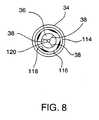
- FIG. 8is an end view of the nose piece 34 and the stylet 36.
- the nose piece 34surrounds the cannula blade 114.
- a garrote groove 116is located within the nose piece 34 and accommodates a garrote (not shown).
- the garrote groove 116includes a number of flat portions 118.
- a central passage 120extends from the stylet 36 through the retracting tube 112 and the stylet retractor handle 20 to accommodate passage of the localization needle 22.
- the garrote(not shown) is mounted to the sleeve 64 and extends through the spline 54 and cannula 30 to the nose piece 34.
- the device 10includes three separate cutting members including the blade 38 of the stylet 36, the circular cannula blade 114, and the garrote.
- the localization needle 22exits the stylet tip 36 through the central passageway 120 and into the lesion.
- the safety wrapper 50is then removed from the guide wire 26 and the guide wire 26 is pushed out the localization needle 22 and deploys in the region of the lesion.
- the device 10is then manually advanced toward the lesion. As the device is advanced the stylet 36 and the blades 38 work in conjunction to transect and separate tissue in route to the lesion. When the stylet 36 is adjacent the lesion manual advancement is stopped.
- the stylet 36is retracted by the stylet retraction handle 20. Rotation of the adjustment knob 44 rotates the gear member 58. Rotation of the gear member 58 advances the spline 54 down the lead screw 68.
- Movement of the spline 54advances the cannula blade 114 which cuts a core of tissue as the cannula blade 114 rotates and advances. Advancement of the cannula blade 114 can be monitored through the window 16. When the front of the gear member 68 becomes visible through the window 16 this indicates that the finger 72 has moved the trigger 18 to the fully unlocked position. At that position the trigger 18 can be pushed toward the cannula 30. This forward motion, through the action of the return cable 102 pulls the collar 76 toward the stylet retractor handle 20. As the collar 76 is pulled toward the stylet retractor handle 20 it engages the sleeve 64 and pulls it toward the stylet retractor handle 20. The retraction of the sleeve 64 causes closure of the garrote thus making a cut transverse to the direction of the advancement of the cannula blade 114 thereby producing a plug containing the lesion. Then the device 10 is removed from the breast.
Landscapes
- Health & Medical Sciences (AREA)
- Life Sciences & Earth Sciences (AREA)
- Medical Informatics (AREA)
- Engineering & Computer Science (AREA)
- Biomedical Technology (AREA)
- Heart & Thoracic Surgery (AREA)
- Pathology (AREA)
- Molecular Biology (AREA)
- Surgery (AREA)
- Animal Behavior & Ethology (AREA)
- General Health & Medical Sciences (AREA)
- Public Health (AREA)
- Veterinary Medicine (AREA)
- Surgical Instruments (AREA)
Description
- This invention relates generally to surgical instruments and, more particularly, to a device for percutaneous incisional breast biopsy.
- The early diagnosis of breast cancer through the use of mammography is very important for reducing the morbidity associated with breast cancer. Early diagnosis enables a physician to treat the breast cancer at a more manageable stage of development.
- Mammography is capable of detecting very small abnormalities in breast tissue. However, mammography usually cannot differentiate between malignant and benign lesions in the breast. Definitive determination of the status of a lesion often requires a histological examination of the suspect tissue.
- One method for obtaining a tissue sample for histological examination is through a biopsy or part or all of the suspect tissue. There are a number of devices and methods for performing a biopsy of the breast. Generally, the procedure requires first placing a localization needle within or near the lesion. A guide wire contained within the localization needle is then deployed. The guide wire usually includes hooks that anchor one end of the guide wire in breast tissue near the lesion. Then a biopsy device that includes a cannula and a stylet that is located within the cannula is inserted over the localization needle and guide wire. The device is inserted through a small incision in the breast tissue near the entry point of the localization needle. The stylet bluntly separates breast tissue as the device is inserted down the guide wire toward the lesion. Advancement of the device is stopped once the tip of the stylet is within or near the lesion. Then, the cannula, which has a cutting surface at its leading edge, is advanced over the stylet and into the tissue thereby cutting a core of tissue. The cutting surface is advanced to a point beyond the end of the guide wire. Then, a second cutting surface, typically a wire garrotte, is activated to perform a cut transverse to the direction the cannula and beyond the end of the guide wire. This second cut releases a plug from the lesion. Then the needle, guide wire, and device are retracted from the breast with the plug. The plug is then histologically examined to determine whether the suspect tissue is malignant or benign.
- The current devices have a number of disadvantages including: the device, localization needle, and guide wire are not manufactured as a single unit; and the devices generally do not have a means for insuring that the garrote wire is located past the end of the guide wire prior to deployment of the garrote. In order to determine whether the garrote is located past the end of the guidewire, a radiographic check is required. Further, the blunt stylet requires substantial force to insert and may cause trauma to the healthy tissue as it passes to the biopsy site.
- EP-A-0761170 relates to apparatus for removing tissue which includes an elongated body defining an opening at a distal end and forming a tissue receiving cavity in communication with the opening, a blunt obturatory at least partially disposed in the tissue receiving cavity, and a cutting member operatively moveable transverse to the elongated body in proximity to the opening.
- US-A-5,353,804 relates to an apparatus for removing suspect breast tissue which includes a penetrating member in the form of a stylet with a tapered front end that can be guided along a localisation guide wire. The apparatus includes a first cutting device in the form of a cannula slidingly engaged with the stylet. A driving assembly is in driving engagement with the cannula and, upon activation, potential energy stored in the driving assembly acts to drive the forward end of the cannula forward of the stylet's forward end so as to define a core cavity. A second cutting device which includes a garrote wire having a looped section positioned within a recess at the forward end of the cannula is also provided. The driving assembly preferably also acts to rotate the cannula with a cam arrangement such that the cannula rotates when being driven forward. The garrote wire is also attached to the rotating cannula such that the wire is drawn up to a stop bead just at the time the cannula reaches its maximum forward extension and further rotation of the cannula results in the contraction of the wire loop and a cutting of a core sample or suspect breast tissue. There is also provided a locating needle having a guide wire mounted within it.
- Therefore, it is desirable to provide a biopsy device manufactured as a unit with a localization needle and a guide wire. Additionally, it is desirable to provide a biopsy device having features to insure that the garrote wire is not deployed until it is past the end of the guide wire. It is also desirable to provide a stylet with cutting members to transect and separate breast tissue and minimize the damage to healthy tissue.
- The present invention overcomes the problem with previous biopsy devices by providing a biopsy device which is manufactured with an integral localization needle and guide wire. In addition, the invention includes means for insuring that the garrote wire is not deployed until the garrote wire is beyond the end of the guide wire. Further, the stylet is provided with a blade with transects tissue as the device is inserted to the biopsy site.
- According to a first aspect of the present invention there is provided a device for removing suspect breast tissue comprising:
- a stylet mounted on a retracting handle, said stylet extending beyond a nosepiece of a cannula and having a tip containing a plurality of blades for transecting tissue and a central passage capable of receiving a localization needle;
- said cannula mounted on a drive mechanism, said cannula having a shaft that supports a cutting surface opposite said drive mechanism;
- said drive mechanism for simultaneously rotating said cannula and moving said cannula in a direction that is transverse to the rotation of said cannula;
- a garrote for performing a cut transverse to the longitudinal axis of the cannula, said garrote mounted adjacent to said cutting surface of said cannula ;
- a trigger for deploying said garrote, said trigger including a locking mechanism for preventing deployment of said garrote prior to movement of said cannula a predetermined distance wherein the locking mechanism has a locked position and an unlocked position, in the locked position the trigger abuts a trigger stop and in the unlocked position a ramp lifts the trigger above the trigger stop;
- a localization needle having a guide wire mounted within said needle, said localization needle is received within the retractor handle on which the stylet is mounted;
- The device includes a cannula having a shaft with a cutting surface on one end of the shaft and the other end of the shaft in engagement with a drive assembly. Adjacent to the cutting surface of the cannula is a second cutting mechanism for making a cut transverse to the cut made by the cannula cutting surface. Located within the cannula shaft is a stylet. The stylet has a tip portion with a blade for transecting and separating tissue and a central chamber for permitting a localization needle to pass through the length of the stylet. The localization needle has an interior chamber permitting passage of a guide wire through the length of the localization needle. The device also includes a lock feature for preventing deployment of the second cutting mechanism until it is past the end of the guide wire.
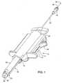
- FIG. 1 is a perspective view of a biopsy device designed according to the invention;
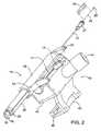
- FIG. 2 is a perspective view of a biopsy device designed according to the invention mounted on an instrument holder;
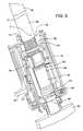
- FIG. 3 is a top perspective view of a biopsy device with a portion of the exterior housing removed;
- FIG. 4 is a perspective view of the drive assembly of a biopsy device designed according to the invention;
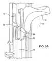
- FIG. 5A is an enlarged perspective view of a portion of the trigger of the biopsy device in the locked position;
- FIG. 5B is a perspective view of a portion of the biopsy device with the trigger in the partially unlocked position;
- FIG. 5C is a perspective view of a portion of the biopsy device with the trigger in the fully unlocked position;
- FIG. 6 is a perspective view of the trigger mechanism of a biopsy device designed according to the invention;
- FIG. 7 is an exploded perspective view of a biopsy device according to the invention; and
- FIG. 8 is an end view of a cannula nose piece designed according to the invention.
- Referring to the figures wherein like numerals indicate like or corresponding parts throughout the several views, in FIG. 1 a biopsy device is shown generally at 10. The
device 10 includes anexterior housing 12 having atrigger slot 14 and awindow 16. Atrigger 18 extends through thetrigger slot 14. A stylet retractor handle 20 is mounted adjacent a rear end of theexterior housing 12. Alocalization needle 22 is received within theretractor handle 20. Ahub 24 is mounted on a distal end of thelocalization needle 22. Aguide wire 26 is slidably received within thelocalization needle 22. Astop 28 is mounted on one end of theguide wire 26. Acannula 30 extends from a front portion of theexterior housing 12. Thecannula 30 comprises ashaft 32 and anosepiece 34. Astylet 36 having a diameter less than the diameter of theshaft 32 extends beyond thenosepiece 34 of thecannula 30. Ablade 38 is mounted within thestylet 36 for transecting and separating tissue as the device is inserted to the biopsy site. - In use, the
biopsy device 10 is inserted by inserting thelocalization needle 22 into the tissue and deploying theguidewire 26 within the localization needle to anchor the device in the breast tissue. Thecannula 30 andstylet 36 are then advanced over the localization needle with the stylet transecting and separating the healthy breast tissue with minimal trauma to the healthy tissue as the cannula is inserted toward the lesion. Thecannula 30 is then advanced to cut a core of tissue. A garrote having a looped section of wire is provided within a recess in the forward end of the cannula. Thetrigger 18 is used to activate the garrote and cut the tissue plug in a direction transverse to the direction in which thecannula 30 was advanced. Thetrigger 18 is provided with a locking mechanism, as will be described below, for preventing deployment of the garrote prior to movement of a cutting plane of the garrote past an end of theguidewire 26. - In FIG. 2, the
device 10 is shown mounted on aninstrument holder 40. Theinstrument holder 40 includes ahousing 42 and anadjustment knob 44 mounted within thehousing 42. Abracket 46 connects thehousing 42 to atrack 48. Thetrack 48 can be fixed at a point along a rail (not shown) by a friction cam brake (not shown). Asafety wrapper 50 is shown adjacent an end of theguide wire 26. Thesafety wrapper 50 is removable prior to deployment of theguide wire 26 and serves to prevent premature deployment of theguide wire 26. The function of thesafety wrapper 50 may also be incorporated in the packaging for the device to prevent premature deployment during transport. - In FIG. 3, a top view of the
device 10 with a portion of theexterior housing 12 removed is shown. Adrive assembly 52 is mounted within theexterior housing 12. Thedrive assembly 52 includes aspline 54 having acylindrical member 56 and agear member 58 separated by ashoulder 60. Aconnector 62 engages thespline 54 with theshaft 32 of thecannula 30. Asleeve 64 is mounted on thecylindrical member 56. Ascrew base 66 is mounted within theexterior housing 12. Alead screw 68 is mounted to thescrew base 66 and extends into thespline 54. Afinger sleeve 70 is mounted within theexterior housing 12 and encircles thegear member 58. Afinger 72 is attached to thefinger sleeve 70. Agear drive 74 is mounted below the gearedmember 58 and engages the gearedmember 58. Acollar 76 encircles thespline 54 and is mounted within theexterior housing 12. Theconnector 62 includes a series offasteners 77. - In FIG. 4, an enlarged view of the
drive assembly 52 is shown. A threadedmember 78 extends from a rear portion of thelead screw 68. The threadedmember 78 threads into the screw base 66 (not shown). Aconnector shaft 80 extends from the front of the gearedmember 58. Acentral passage 82 extends through theconnector shaft 80,spline 54,lead screw 68, and the threadedmember 78. Thecentral passage 82 accommodates the localization needle 22 (not shown). Theconnector shaft 80 includesseveral slots 84 for receiving thefasteners 77 of theconnector 62. - In FIGS. 5A-5C, the
trigger 18 is shown in the three stages of fully locked, partially unlocked, and fully unlocked, respectively. In FIG. 5A, thetrigger 18 is shown in the fully locked position. A V-shapedbend 86 in thefinger 72 is positioned adjacent a rampedportion 88 of atrigger bracket 90. Astop 92 formed in theexterior housing 12 prevents thetrigger 18 from moving in the direction ofarrow 94 toward the cannula 30 (not shown). - In FIG. 5B, the
trigger 18 is shown in the partially unlocked position. Rotation of the adjustment knob 44 (not shown) rotates thedrive gear 74 which in turn rotates thegear member 58. Rotation of thegear member 58 causes movement of thespline 54 along the length of thelead screw 68. When theshoulder 60 advances sufficiently to contact thefinger sleeve 70. additional forward movement of thespline 54 pulls thefinger sleeve 70 and the attachedfinger 52 forward. Advancement of thefinger 72 causes the V-shapedbend 86 to ride up the rampedportion 88 of thetrigger bracket 90. The movement of the V-shapedbend 86 pushes thetrigger 18 outwardly in the direction ofarrow 96. - In FIG. 5C, the
trigger 18 is shown in the fully unlocked position. As further rotation of thegear drive 74 causes further advancement of thespline 54, theshoulder 60 continues to advance thefinger sleeve 70 and thefinger 72. When the V-shapedbend 86 moves off the rampedportion 88 and onto aflat portion 98 of thetrigger bracket 90 thetrigger bracket 90 is moved outside of thestop 92 and thetrigger 18 can be freely advanced in the direction ofarrow 100. - In FIG. 6, a partial side view of the trigger mechanism of the device is shown. Specifically, the routing pathway of a
return cable 102 is shown. Each end of thereturn cable 102 is split into a pair oftails 104. One end of thereturn cable 102 is connected by a pair ofstops 106 to an upper portion of thecollar 76. Thereturn cable 102 is routed through one of a pair of diametricallyopposed holes 108 in thescrew base 66 and around acable post 10. Thereturn cable 102 passes from thecable post 110 to thetrigger bracket 90 and passes partially around a post (not shown) on thetrigger bracket 90. Thereturn cable 102 is then routed back around thecable post 110, through the other of theholes 108, and connects to a bottom portion of thecollar 76. - In FIG. 7, a partial exploded view of the
biopsy device 10 is shown. Thestylet 36 is mounted to one end of a retractingtube 112 that extends through theshaft 32 of thecannula 30, thecentral passage 82, and is fixedly mounted to the stylet retractor handle 20 (not shown). Acircular cannula blade 114 is mounted over thestylet 36 onto anose piece 34. - FIG. 8 is an end view of the
nose piece 34 and thestylet 36. Thenose piece 34 surrounds thecannula blade 114. Agarrote groove 116 is located within thenose piece 34 and accommodates a garrote (not shown). Thegarrote groove 116 includes a number offlat portions 118. Acentral passage 120 extends from thestylet 36 through the retractingtube 112 and the stylet retractor handle 20 to accommodate passage of thelocalization needle 22. The garrote (not shown) is mounted to thesleeve 64 and extends through thespline 54 andcannula 30 to thenose piece 34. As described above, thedevice 10 includes three separate cutting members including theblade 38 of thestylet 36, thecircular cannula blade 114, and the garrote. - In the use of the
device 10, thelocalization needle 22 exits thestylet tip 36 through thecentral passageway 120 and into the lesion. Thesafety wrapper 50 is then removed from theguide wire 26 and theguide wire 26 is pushed out thelocalization needle 22 and deploys in the region of the lesion. Thedevice 10 is then manually advanced toward the lesion. As the device is advanced thestylet 36 and theblades 38 work in conjunction to transect and separate tissue in route to the lesion. When thestylet 36 is adjacent the lesion manual advancement is stopped. Thestylet 36 is retracted by the stylet retraction handle 20. Rotation of theadjustment knob 44 rotates thegear member 58. Rotation of thegear member 58 advances thespline 54 down thelead screw 68. Movement of thespline 54 advances thecannula blade 114 which cuts a core of tissue as thecannula blade 114 rotates and advances. Advancement of thecannula blade 114 can be monitored through thewindow 16. When the front of thegear member 68 becomes visible through thewindow 16 this indicates that thefinger 72 has moved thetrigger 18 to the fully unlocked position. At that position thetrigger 18 can be pushed toward thecannula 30. This forward motion, through the action of thereturn cable 102 pulls thecollar 76 toward thestylet retractor handle 20. As thecollar 76 is pulled toward the stylet retractor handle 20 it engages thesleeve 64 and pulls it toward thestylet retractor handle 20. The retraction of thesleeve 64 causes closure of the garrote thus making a cut transverse to the direction of the advancement of thecannula blade 114 thereby producing a plug containing the lesion. Then thedevice 10 is removed from the breast.
wherein the rotation of the gear member also advances the cannula to cut a core of tissue.
Claims (7)
- A device (10) for removing suspect breast tissue comprising:a stylet (36) mounted on a retracting handle (20), said stylet (36) extending beyond a nosepiece (34) of a cannula (30) and having a tip containing a plurality of blades (38) for transecting tissue and a central passage (120) capable of receiving a localization needle (122);said cannula (30) mounted on a drive mechanism (52), said cannula (30) having a shaft (32) that supports a cutting surface opposite said drive mechanism (52);said drive mechanism (52) for simultaneously rotating said cannula (30) and moving said cannula (30) in a direction that is transverse to the rotation of said cannula (30);a garrote for performing a cut transverse to the longitudinal axis of the cannula (30), said garrote mounted adjacent to said cutting surface of said cannula (30);a trigger (18) for deploying said garrote, said trigger (18) including a locking mechanism for preventing deployment of said garrote prior to movement of said cannula (30) a predetermined distance wherein the locking mechanism has a locked position and an unlocked position, in the locked position the trigger (18) abuts a trigger stop (92) and in the unlocked position a ramp (88) lifts the trigger (18) above the trigger stop (92);a localization needle (22) having a guide wire (26) mounted within said needle (22), said localization needle (22) is received within the retractor handle (20) on which the stylet (36) is mounted;wherein upon actuation of the cannula (30) the locking mechanism is moved from a locked position to an unlocked position by rotation of a gear member (58) which causes longitudinal motion of a spline (54); and
wherein the rotation of the gear member (58) also advances the cannula (30) to cut a core of tissue. - The device (10) for removing suspect breast tissue of claim 1, wherein said guide wire (26) is movable within the localization needle (22).
- The device (10) for removing suspect breast tissue of claim 2, wherein the locking mechanism prevents deployment of the garrote until a cutting plane of the garrote is beyond an end of the guide wire (26).
- The device (10) for removing suspect breast tissue of claim 2, wherein the guide wire (26) includes a hook that anchors one end of the guide wire (26) in the breast tissue.
- The device (10) for removing suspect breast tissue of claim 2, further comprising means for preventing premature deployment of the guide wire (26).
- The device (10) for removing suspect breast tissue of claim 1, wherein the ramp (88) moves along a longitudinal axis of the device (10).
- The device (10) for removing suspect breast tissue of claim 1, wherein when the trigger (18) is in the unlocked position, the trigger (18) can be advanced to deploy the garrote and cut a plug of tissue.
Applications Claiming Priority (3)
| Application Number | Priority Date | Filing Date | Title |
|---|---|---|---|
| US5869197P | 1997-09-12 | 1997-09-12 | |
| US58691 | 1997-09-12 | ||
| PCT/US1998/018172WO1999013775A1 (en) | 1997-09-12 | 1998-09-14 | Incisional breast biopsy device |
Publications (2)
| Publication Number | Publication Date |
|---|---|
| EP1011455A1 EP1011455A1 (en) | 2000-06-28 |
| EP1011455B1true EP1011455B1 (en) | 2007-01-10 |
Family
ID=22018328
Family Applications (1)
| Application Number | Title | Priority Date | Filing Date |
|---|---|---|---|
| EP98946807AExpired - LifetimeEP1011455B1 (en) | 1997-09-12 | 1998-09-14 | Incisional breast biopsy device |
Country Status (7)
| Country | Link |
|---|---|
| EP (1) | EP1011455B1 (en) |
| JP (1) | JP2001516607A (en) |
| AU (1) | AU745686B2 (en) |
| CA (1) | CA2302158C (en) |
| DE (1) | DE69836862T2 (en) |
| ES (1) | ES2280100T3 (en) |
| WO (1) | WO1999013775A1 (en) |
Families Citing this family (9)
| Publication number | Priority date | Publication date | Assignee | Title |
|---|---|---|---|---|
| US6363940B1 (en) | 1998-05-14 | 2002-04-02 | Calypso Medical Technologies, Inc. | System and method for bracketing and removing tissue |
| AU2002211568B2 (en) | 2000-10-16 | 2005-11-17 | Sanarus Medical, Inc. | Device for biopsy of tumors |
| US7135978B2 (en) | 2001-09-14 | 2006-11-14 | Calypso Medical Technologies, Inc. | Miniature resonating marker assembly |
| US6855140B2 (en) | 2002-06-06 | 2005-02-15 | Thomas E. Albrecht | Method of tissue lesion removal |
| US7066893B2 (en) | 2002-06-06 | 2006-06-27 | Ethicon Endo-Surgery, Inc. | Biopsy method |
| US6981949B2 (en) | 2002-06-06 | 2006-01-03 | Ethicon Endo-Surgery, Inc. | Perimeter cut biopsy probe |
| US6889833B2 (en) | 2002-12-30 | 2005-05-10 | Calypso Medical Technologies, Inc. | Packaged systems for implanting markers in a patient and methods for manufacturing and using such systems |
| US7289839B2 (en) | 2002-12-30 | 2007-10-30 | Calypso Medical Technologies, Inc. | Implantable marker with a leadless signal transmitter compatible for use in magnetic resonance devices |
| US8597201B2 (en) | 2010-03-30 | 2013-12-03 | Siteselect Medical Technologies, Inc. | Tissue excision device with a flexible transection blade |
Family Cites Families (4)
| Publication number | Priority date | Publication date | Assignee | Title |
|---|---|---|---|---|
| AT290712B (en)* | 1969-06-30 | 1971-06-11 | Hubert Dr Reinisch | Biopsy collection device |
| US5353804A (en)* | 1990-09-18 | 1994-10-11 | Peb Biopsy Corporation | Method and device for percutaneous exisional breast biopsy |
| US5645556A (en)* | 1990-12-18 | 1997-07-08 | Yoon; Inbae | Safety penetrating instrument with triggered penetrating member retraction and single or multiple safety member protrusion |
| US5817034A (en)* | 1995-09-08 | 1998-10-06 | United States Surgical Corporation | Apparatus and method for removing tissue |
- 1998
- 1998-09-14EPEP98946807Apatent/EP1011455B1/ennot_activeExpired - Lifetime
- 1998-09-14DEDE69836862Tpatent/DE69836862T2/ennot_activeExpired - Lifetime
- 1998-09-14JPJP2000511409Apatent/JP2001516607A/enactivePending
- 1998-09-14CACA002302158Apatent/CA2302158C/ennot_activeExpired - Fee Related
- 1998-09-14ESES98946807Tpatent/ES2280100T3/ennot_activeExpired - Lifetime
- 1998-09-14AUAU93743/98Apatent/AU745686B2/ennot_activeCeased
- 1998-09-14WOPCT/US1998/018172patent/WO1999013775A1/enactiveIP Right Grant
Also Published As
| Publication number | Publication date |
|---|---|
| CA2302158A1 (en) | 1999-03-25 |
| AU9374398A (en) | 1999-04-05 |
| EP1011455A1 (en) | 2000-06-28 |
| DE69836862D1 (en) | 2007-02-22 |
| JP2001516607A (en) | 2001-10-02 |
| ES2280100T3 (en) | 2007-09-01 |
| CA2302158C (en) | 2009-02-24 |
| DE69836862T2 (en) | 2007-10-25 |
| WO1999013775A1 (en) | 1999-03-25 |
| AU745686B2 (en) | 2002-03-28 |
Similar Documents
| Publication | Publication Date | Title |
|---|---|---|
| US6080113A (en) | Incisional breast biopsy device | |
| US6551253B2 (en) | Incisional breast biopsy device | |
| US6383145B1 (en) | Incisional breast biopsy device | |
| US11779431B2 (en) | Marker delivery device for tissue marker placement | |
| CA2494377C (en) | Biopsy devices and methods | |
| US4774948A (en) | Marking and retraction needle having retrievable stylet | |
| EP0499457B1 (en) | Trocar | |
| US5560373A (en) | Needle core biopsy instrument with durable or disposable cannula assembly | |
| US9301808B2 (en) | Apparatus for inserting a surgical device at least partially through a wound opening | |
| US6080114A (en) | Method for coaxial breast biopsy | |
| EP2520227A1 (en) | Device for removing tissue from a patient and placing a marker in the patient | |
| EP1011455B1 (en) | Incisional breast biopsy device | |
| EP3057513B1 (en) | Biopsy device | |
| EP3292822A2 (en) | Biopsy device | |
| WO1997032530A1 (en) | Cannula for a trocar system |
Legal Events
| Date | Code | Title | Description |
|---|---|---|---|
| PUAI | Public reference made under article 153(3) epc to a published international application that has entered the european phase | Free format text:ORIGINAL CODE: 0009012 | |
| 17P | Request for examination filed | Effective date:20000308 | |
| AK | Designated contracting states | Kind code of ref document:A1 Designated state(s):AT BE CH CY DE DK ES FI FR GB GR IE IT LI LU MC NL PT SE | |
| 17Q | First examination report despatched | Effective date:20040526 | |
| GRAP | Despatch of communication of intention to grant a patent | Free format text:ORIGINAL CODE: EPIDOSNIGR1 | |
| RAP1 | Party data changed (applicant data changed or rights of an application transferred) | Owner name:SITESELECT MEDICAL TECHNOLOGIES, LTD. | |
| GRAS | Grant fee paid | Free format text:ORIGINAL CODE: EPIDOSNIGR3 | |
| GRAA | (expected) grant | Free format text:ORIGINAL CODE: 0009210 | |
| AK | Designated contracting states | Kind code of ref document:B1 Designated state(s):AT BE CH CY DE DK ES FI FR GB GR IE IT LI LU MC NL PT SE | |
| PG25 | Lapsed in a contracting state [announced via postgrant information from national office to epo] | Ref country code:NL Free format text:LAPSE BECAUSE OF FAILURE TO SUBMIT A TRANSLATION OF THE DESCRIPTION OR TO PAY THE FEE WITHIN THE PRESCRIBED TIME-LIMIT Effective date:20070110 Ref country code:LI Free format text:LAPSE BECAUSE OF FAILURE TO SUBMIT A TRANSLATION OF THE DESCRIPTION OR TO PAY THE FEE WITHIN THE PRESCRIBED TIME-LIMIT Effective date:20070110 Ref country code:FI Free format text:LAPSE BECAUSE OF FAILURE TO SUBMIT A TRANSLATION OF THE DESCRIPTION OR TO PAY THE FEE WITHIN THE PRESCRIBED TIME-LIMIT Effective date:20070110 Ref country code:DK Free format text:LAPSE BECAUSE OF FAILURE TO SUBMIT A TRANSLATION OF THE DESCRIPTION OR TO PAY THE FEE WITHIN THE PRESCRIBED TIME-LIMIT Effective date:20070110 Ref country code:CH Free format text:LAPSE BECAUSE OF FAILURE TO SUBMIT A TRANSLATION OF THE DESCRIPTION OR TO PAY THE FEE WITHIN THE PRESCRIBED TIME-LIMIT Effective date:20070110 Ref country code:AT Free format text:LAPSE BECAUSE OF FAILURE TO SUBMIT A TRANSLATION OF THE DESCRIPTION OR TO PAY THE FEE WITHIN THE PRESCRIBED TIME-LIMIT Effective date:20070110 | |
| REG | Reference to a national code | Ref country code:GB Ref legal event code:FG4D | |
| REG | Reference to a national code | Ref country code:IE Ref legal event code:FG4D | |
| REF | Corresponds to: | Ref document number:69836862 Country of ref document:DE Date of ref document:20070222 Kind code of ref document:P | |
| PG25 | Lapsed in a contracting state [announced via postgrant information from national office to epo] | Ref country code:SE Free format text:LAPSE BECAUSE OF FAILURE TO SUBMIT A TRANSLATION OF THE DESCRIPTION OR TO PAY THE FEE WITHIN THE PRESCRIBED TIME-LIMIT Effective date:20070410 | |
| PG25 | Lapsed in a contracting state [announced via postgrant information from national office to epo] | Ref country code:PT Free format text:LAPSE BECAUSE OF FAILURE TO SUBMIT A TRANSLATION OF THE DESCRIPTION OR TO PAY THE FEE WITHIN THE PRESCRIBED TIME-LIMIT Effective date:20070611 | |
| NLV1 | Nl: lapsed or annulled due to failure to fulfill the requirements of art. 29p and 29m of the patents act | ||
| REG | Reference to a national code | Ref country code:CH Ref legal event code:PL | |
| ET | Fr: translation filed | ||
| REG | Reference to a national code | Ref country code:ES Ref legal event code:FG2A Ref document number:2280100 Country of ref document:ES Kind code of ref document:T3 | |
| PLBE | No opposition filed within time limit | Free format text:ORIGINAL CODE: 0009261 | |
| STAA | Information on the status of an ep patent application or granted ep patent | Free format text:STATUS: NO OPPOSITION FILED WITHIN TIME LIMIT | |
| 26N | No opposition filed | Effective date:20071011 | |
| PG25 | Lapsed in a contracting state [announced via postgrant information from national office to epo] | Ref country code:BE Free format text:LAPSE BECAUSE OF FAILURE TO SUBMIT A TRANSLATION OF THE DESCRIPTION OR TO PAY THE FEE WITHIN THE PRESCRIBED TIME-LIMIT Effective date:20070110 | |
| PG25 | Lapsed in a contracting state [announced via postgrant information from national office to epo] | Ref country code:MC Free format text:LAPSE BECAUSE OF NON-PAYMENT OF DUE FEES Effective date:20070930 Ref country code:GR Free format text:LAPSE BECAUSE OF FAILURE TO SUBMIT A TRANSLATION OF THE DESCRIPTION OR TO PAY THE FEE WITHIN THE PRESCRIBED TIME-LIMIT Effective date:20070411 | |
| PG25 | Lapsed in a contracting state [announced via postgrant information from national office to epo] | Ref country code:IE Free format text:LAPSE BECAUSE OF NON-PAYMENT OF DUE FEES Effective date:20070914 | |
| PG25 | Lapsed in a contracting state [announced via postgrant information from national office to epo] | Ref country code:CY Free format text:LAPSE BECAUSE OF FAILURE TO SUBMIT A TRANSLATION OF THE DESCRIPTION OR TO PAY THE FEE WITHIN THE PRESCRIBED TIME-LIMIT Effective date:20070110 | |
| PG25 | Lapsed in a contracting state [announced via postgrant information from national office to epo] | Ref country code:LU Free format text:LAPSE BECAUSE OF NON-PAYMENT OF DUE FEES Effective date:20070914 | |
| PGFP | Annual fee paid to national office [announced via postgrant information from national office to epo] | Ref country code:GB Payment date:20120912 Year of fee payment:15 | |
| PGFP | Annual fee paid to national office [announced via postgrant information from national office to epo] | Ref country code:IT Payment date:20120912 Year of fee payment:15 Ref country code:FR Payment date:20120926 Year of fee payment:15 Ref country code:DE Payment date:20120912 Year of fee payment:15 | |
| PGFP | Annual fee paid to national office [announced via postgrant information from national office to epo] | Ref country code:ES Payment date:20121004 Year of fee payment:15 | |
| GBPC | Gb: european patent ceased through non-payment of renewal fee | Effective date:20130914 | |
| REG | Reference to a national code | Ref country code:DE Ref legal event code:R119 Ref document number:69836862 Country of ref document:DE Effective date:20140401 | |
| REG | Reference to a national code | Ref country code:FR Ref legal event code:ST Effective date:20140530 | |
| PG25 | Lapsed in a contracting state [announced via postgrant information from national office to epo] | Ref country code:GB Free format text:LAPSE BECAUSE OF NON-PAYMENT OF DUE FEES Effective date:20130914 | |
| PG25 | Lapsed in a contracting state [announced via postgrant information from national office to epo] | Ref country code:DE Free format text:LAPSE BECAUSE OF NON-PAYMENT OF DUE FEES Effective date:20140401 Ref country code:IT Free format text:LAPSE BECAUSE OF NON-PAYMENT OF DUE FEES Effective date:20130914 Ref country code:FR Free format text:LAPSE BECAUSE OF NON-PAYMENT OF DUE FEES Effective date:20130930 | |
| REG | Reference to a national code | Ref country code:ES Ref legal event code:FD2A Effective date:20141008 | |
| PG25 | Lapsed in a contracting state [announced via postgrant information from national office to epo] | Ref country code:ES Free format text:LAPSE BECAUSE OF NON-PAYMENT OF DUE FEES Effective date:20130915 |