EP1011227A2 - Apparatus and method for flow-level demultiplexing - Google Patents
Apparatus and method for flow-level demultiplexingDownload PDFInfo
- Publication number
- EP1011227A2 EP1011227A2EP99309743AEP99309743AEP1011227A2EP 1011227 A2EP1011227 A2EP 1011227A2EP 99309743 AEP99309743 AEP 99309743AEP 99309743 AEP99309743 AEP 99309743AEP 1011227 A2EP1011227 A2EP 1011227A2
- Authority
- EP
- European Patent Office
- Prior art keywords
- packet
- data flow
- output port
- packets
- router
- Prior art date
- Legal status (The legal status is an assumption and is not a legal conclusion. Google has not performed a legal analysis and makes no representation as to the accuracy of the status listed.)
- Withdrawn
Links
- 238000000034methodMethods0.000titleclaimsdescription12
- 230000005540biological transmissionEffects0.000claimsdescription20
- 238000004891communicationMethods0.000description5
- 238000010586diagramMethods0.000description4
- 230000008901benefitEffects0.000description2
- 238000005516engineering processMethods0.000description2
- 230000007774longtermEffects0.000description2
- 238000012986modificationMethods0.000description2
- 230000004048modificationEffects0.000description2
- 239000013307optical fiberSubstances0.000description2
- 230000002776aggregationEffects0.000description1
- 238000004220aggregationMethods0.000description1
- 238000013459approachMethods0.000description1
- 230000009172burstingEffects0.000description1
- 230000001934delayEffects0.000description1
- 238000005538encapsulationMethods0.000description1
- 230000006855networkingEffects0.000description1
- 230000011218segmentationEffects0.000description1
Images

Classifications
- H—ELECTRICITY
- H04—ELECTRIC COMMUNICATION TECHNIQUE
- H04L—TRANSMISSION OF DIGITAL INFORMATION, e.g. TELEGRAPHIC COMMUNICATION
- H04L45/00—Routing or path finding of packets in data switching networks
- H—ELECTRICITY
- H04—ELECTRIC COMMUNICATION TECHNIQUE
- H04L—TRANSMISSION OF DIGITAL INFORMATION, e.g. TELEGRAPHIC COMMUNICATION
- H04L45/00—Routing or path finding of packets in data switching networks
- H04L45/24—Multipath
- H—ELECTRICITY
- H04—ELECTRIC COMMUNICATION TECHNIQUE
- H04L—TRANSMISSION OF DIGITAL INFORMATION, e.g. TELEGRAPHIC COMMUNICATION
- H04L45/00—Routing or path finding of packets in data switching networks
- H04L45/38—Flow based routing
- H—ELECTRICITY
- H04—ELECTRIC COMMUNICATION TECHNIQUE
- H04L—TRANSMISSION OF DIGITAL INFORMATION, e.g. TELEGRAPHIC COMMUNICATION
- H04L9/00—Cryptographic mechanisms or cryptographic arrangements for secret or secure communications; Network security protocols
- H04L9/40—Network security protocols
- H—ELECTRICITY
- H04—ELECTRIC COMMUNICATION TECHNIQUE
- H04L—TRANSMISSION OF DIGITAL INFORMATION, e.g. TELEGRAPHIC COMMUNICATION
- H04L69/00—Network arrangements, protocols or services independent of the application payload and not provided for in the other groups of this subclass
- H04L69/14—Multichannel or multilink protocols
Definitions
- This inventionrelates generally to data routing systems and more specifically to data routing systems over multiple physical links.
- Physical linka single point-to-point (PPP) serial transmission link between two nodes in the network (such as between two routers or between a router and a host machine).
- PPPpoint-to-point
- the implementation of a serial linkmay take various forms such as an optical fibre or a wavelength segment on an optical fibre, among other options.
- Physical input/output portthe input/output port of the router that supports one physical link.
- Logical linka point-to-point traffic path between two routers that is composed of multiple physical links and appears from a routing point of view to be one link.
- Logical input/output portthe collection of physical input/output ports that support the physical links of a logical link.
- Supertrunkthe aggregation of physical links into larger, logical links.
- Transmission Control Protocola library of routines that applications can use when they need reliable network communications with another computer. TCP is responsible for verifying the correct delivery of data from client to server. It adds support to detect errors or lost data and to trigger reconstruction until the data is correctly and completely received.
- IPInternet Protocol
- multi-link routesare attractive. In situations where routers are clustered in close physical proximity, the use of multiple links might allow the interconnect to be multiple low cost links rather than single high cost connections. Another reason is that the application of the multi-link approach might also be a fast way to provide higher rate ports on existing routers. Yet another reason is that the use of multiple links allows more granularity of growth than the large steps in the transmission network and so may allow savings in bandwidth costs. Finally, another reason is that multiple links can allow for redundancy to cover link failure without requiring the spare link to cover the whole bandwidth of the route.
- TCPTransmission Control Protocol
- the TCPcan accommodate some mis-ordering of packets, but there is a problem if too much mis-ordering occurs on a connection where the transmitter is using the fast retransmission protocol.
- This mis-ordering of packetsforces routers receiving these packets to comprise a sorting function that is capable of re-ordering the packets into the proper order.
- This sorting functionis likely to be relatively complex and cause a delay in the delivery of data flows to the destination.
- the receiving routeris not setup for receiving packets of a single flow along multiple physical links and therefore does not have a sorting function, significant errors would occur within the transmission, delaying it further.
- a routeris required that will allow the use of multiple physical links for transmitting data traffic without requiring re-ordering of packets or any other special functions at the receiving router. This router must ensure that the order of the packets during transmission is maintained, but still allow for efficient load balancing between physical links.
- the present inventionprovides a forwarding node capable of operation within a router that transfers digital data with a plurality of other routers within a packet routing system, the forwarding node comprising: a load balancing device that, when input with individual packets of a data flow, reads a logical output port corresponding to the data flow, assigns the data flow to a physical output port within the logical output port based upon physical link criteria, and outputs the individual packets to their assigned physical output port.
- the present inventionprovides a router capable of operation within a packet routing system that transfers digital data between a plurality of the routers, the router comprising: a route controller; a rotator space switch; at least one first forwarding node, coupled to both the route controller and the rotator space switch, comprising a load balancing device that, when input with individual packets of a data flow, reads a logical output port corresponding to the data flow, assigns the data flow to a physical output port within the logical output port based upon physical link criteria, and outputs the individual packets to their assigned physical output port; and at least one second forwarding node, coupled to both the route controller and the rotator space switch, that is arranged to operate as a physical output port for outputting packets to at least one transmission apparatus.
- the present inventionprovides a packet routing system that transfers digital data between at least one first router and at least one second router, the packet routing system comprising: the first router comprising: a route controller; a rotator space switch; at least one first forwarding node, coupled to both the route controller and the rotator space switch, comprising a load balancing device that, when input with individual packets of a data flow, reads a logical output port corresponding to the data flow, assigns the data flow to a physical output port within the logical output port based upon physical link criteria, and outputs the individual packets to their assigned physical output port; and at least one second forwarding node, coupled to both the route controller and the rotator space switch, that is arranged to operate as a physical output port for outputting packets to at least one transmission apparatus; a plurality of transmission apparatuses coupled between the first and second routers; and the second router comprising: a second route controller; a second rotator space switch; at least one third forwarding node,
- the present inventionprovides in a packet routing system comprising a plurality of routers, a method of transferring digital data between the routers comprising the steps of: inputting individual packets of a data flow into a first router; reading a logical output port corresponding to the data flow of the individual packets; assigning each of the data flows to a physical output port within the logical output port based upon physical link criteria; transmitting each of the packets, via their assigned physical output ports, to a second router; and outputting a data flow corresponding to the packets received at the second router.
- the present inventiontherefore advantageously provides an apparatus and method for increasing the efficiency of data communications.
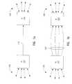
- FIGURES 1a and 1billustrate example logical and physical routing systems respectively that depict communication links from a first router 102 to a second router 104. Both the first and second routers 102,104 are connected to a plurality of other communication links 106,108 respectively.
- a logical link 110is shown coupled between the routers 102,104.
- the logical linkis a 3.5 Gb/s connection.
- FIGURE 1billustrates a series of physical links 112, that make up a supertrunk, coupled between the routers 102,104 that together are equivalent to the logical link 110.
- the supertrunk 112in this example, comprises four physical links that when combined total the 3.5 Gb/s of the logical link 110.
- Each of the physical links 112 depicted in FIGURE 1bmay be implemented with a series of connections within a series of different networks. Despite appearing within FIGURE 1b as being directly connected and physically local, it should be understood that physical links 112 are typically quite complex with the routers 102,104 possibly a large distance from each other.
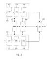
- FIGURE 2is a block diagram of a routing system between the first router 102 and the second router 104 illustrating an example application of the preferred embodiment of the present invention.
- Each router 102,104comprises a rotator space switch 202, a route controller 204, and a plurality of transport nodes 206.
- the routers 102,104 depicted in FIGURE 2each comprise two transport nodes, though this is not meant to limit the scope of the present invention.
- the rotator space switch 202 and the route controller 204are independently coupled to each transport node 206, although, within FIGURE 2, the route controller 204 is only shown to be coupled to one transport node 206 via signal bus 208.
- Each transport node 206comprises a plurality of Internet Protocol Forwarding (IPF) nodes 210,212,214,216,218.
- IPFInternet Protocol Forwarding
- each transport node 206comprises four IPF nodes, though this is not meant to limit the scope of the present invention.
- the routers 102,104in an alternative embodiment, do not comprise transport nodes, but instead have a plurality of IPF nodes, coupled independently to the route controller 204 and the rotator space switch 202, that are not within transport nodes.
- the IPF nodeswithin the system depicted in FIGURE 2, include an input IPF node 210, a plurality of supertrunk output IPF nodes 212 representing a single logical output port, a plurality of supertrunk input IPF nodes 214 representing a single logical input port, an output IPF node 216, and a plurality of other IPF nodes 218 which are unrelated to the description herein below of an example application of the preferred embodiment of the present invention.
- Each IPF nodeis identical.
- any one of the IPF nodesmay, in practice, be an input IPF node, a supertrunk output IPF node, a supertrunk input IPF node, or an output IPF node.
- the input IPF node 210is within a transport node of the first router 102 and is input with a TCP input signal (TCPIN) via line 220.
- TCPINTCP input signal
- the input IPF node 210is coupled to the rotator space switch 202 of the first router 102 via line 222.
- the plurality of supertrunk output IPF nodes 212are spread across the transport nodes 206 of the first router 102. In this example, there are four supertrunk output IPF nodes 212 with two in each transport node 206 of the first router 102, though other configurations are possible.
- the supertrunk output IPF nodes 212are each independently coupled to the rotator space switch 202 of the first router 102 via lines 224 and, via the supertrunk 112, to the second router 104.
- the supertrunk 112comprises physical links 226a,226b,226c,226d between the supertrunk output IPF nodes 212 (the physical output ports) within the first router 102 and the supertrunk input IPF nodes 214 (the physical input ports) within the second router 104.
- the supertrunk input IPF nodes 214are spread across the two transport nodes 206 of the second router 104. In this example, there are four supertrunk input IPF nodes 214, three in one transport node 206 and one in the other. This illustrated configuration is not meant to limit the scope of the present invention and it should be recognized that the number of supertrunk input IPF nodes 214 does not have to equal the number of supertrunk output IPF nodes 212.
- a single supertrunk output IPF node 212could be coupled via a plurality of physical links to a plurality of supertrunk input IPF nodes 214 and a plurality of supertrunk output IPF nodes 212 could be coupled to the same supertrunk input IPF node 214.
- Each of the supertrunk input IPF nodes 214are independently coupled to the rotator space switch 202 of the second router 104 via lines 228.
- the output IPF node 216is within the transport node 206 of the second router 104 that has only one supertrunk input IPF node 214, but it is recognized that the output IPF node 216 could be located in any transport node 206 of the second router 104.
- the output IPF node 216is coupled to the rotator space switch 202 of the second router 104 via line 230 and outputs a TCP output signal (TCPOUT) via line 232.
- the other IPF nodes 218are simply shown within FIGURE 2 to illustrate that other operations are being performed concurrently with the example application described herein below.
- Each of the other IPF nodes 218is coupled to the rotator space switches 202 of the respective router 102,104 via lines 234.
- the TCPINwhich is a series of packets that comprise a data flow (a TCP over IP stream in the preferred embodiment), is input to the input IPF node 210 packet by packet.
- the input IPF node 210attaches a Packet Forwarding Header (PFH), described in detail herein below, and a Rotator Information Unit (RIU) header to each packet.
- PHPacket Forwarding Header
- RIURotator Information Unit
- the RIU headercomprises a physical output port indicator that corresponds to a particular physical output port 212 determined, with use of a load balancing function also described in detail herein below, for the particular data flow in which the packet is comprised.
- the supertrunk output IPF node 212when sequentially input with the packets of a data flow then proceeds to remove the PFH and RIU header from each of the packets and outputs the packets of the data flow to a physical link 112 between the first and second routers 102,104.
- the data flowsare received packet by packet at the supertrunk input IPF nodes 214 and forwarded to the output IPF node 216 via the lines 228, the rotator space switch 202 of the second router 104, and the line 230.
- the output IPF node 216outputs TCPOUT which, in this case, is a series of packets that comprise a data flow consistent with the data flow of TCPIN.
- each IPF nodecomprises an ingress block 302, an egress block 304, a Space Switch Interface (SSI) 306, an Embedded Processor Interface (EPI) 308, and a Router Monitor (RMON) 310.
- the ingress block 302comprises an Ingress Convergence Processor (ICP) 312 coupled in series with an Ingress Filter and Mapper (IFM) 314, and an Ingress Port Controller (IPC) 316 further coupled to the SSI 306.
- ICPIngress Convergence Processor
- IAMIngress Filter and Mapper
- IPCIngress Port Controller
- the egress block 304comprises an Egress Packet Queuer (EPQ) 318 coupled to the SSI 306 and further coupled in series with an Egress Packet Scheduler (EPS) 320, and an Egress Convergence Processor (ECP) 322. It is noted that according to the preferred embodiment, all of these components are discrete devices, though in alternative embodiments some or all of these components could be combined or implemented within software.
- EPQEgress Packet Queuer
- EPSEgress Packet Scheduler
- ECPEgress Convergence Processor
- the EPI 308, in the preferred embodiment,is coupled to the components of both the ingress and egress blocks 302,304 along with the SSI 306 and the RMON 310.
- the RMON 310is further coupled to at least one component in each of the ingress and egress blocks 302,304.
- the RMON 310is coupled to the outputs of the IPC 316 and the EPS 320.
- the EPI 308is the local processor for the IPF node that performs numerous processor related functions.
- the RMON 310is utilized as a central point for all counters within the IPF node.
- the ICP 312terminates the ingress physical and link layer interfaces, verifies the link layer, IP headers, and formatting, maps the incoming packets to a Receive Context Identifier (RCI) that is a generic tag to uniquely identify the logical interface that a packet arrived on, and encapsulates each of the individual packets with a PFH.
- RCIReceive Context Identifier
- the PFHcomprises four 32 bit words.
- the first word 402comprises a 4 bit Start Of Packet Offset (SOP_OFFS) signal that indicates the position of the first word of the packet to be sent to the link layer for segmentation, an 8 bit Virtual Private Network Identifier (VPN_ID) signal that identifies the virtual private network or virtual router interface that the packet arrived on, and the 20 bit RCI.
- the second word 404comprises 32 bits of Packet Forwarding Flags (PF_FLAGS) that are a collection of generic status and control flags.
- the third word 406comprises 32 reserved bits not utilized in the preferred embodiment of the present invention.
- the fourth word 408comprises a 24 bit Egress Context Identifier (ECI) that is the result of a forwarding look-up function and is somewhat analogous to a flow identifier, and an 8 bit PFH Integrity Check (CRC).
- ECIEgress Context Identifier
- CRCPFH Integrity Check
- the contents of the first word 402 of the PFHare determined and inserted by the ICP 312 while the contents of the second word 404 can be set or modified by each of the blocks of the IPF node.
- the fourth word 408is reserved space by the ICP 312, but the contents of the fourth word 408 are determined and inserted by another device as will described herein below.
- the outputted packets from the ICP 312are input to the IFM 314 which maps the incoming packets to the logical ECI, inserts the ECI into the PFH, and filters packets based on a configured policy.
- the IPC 316then receives the packets, performs the load balancing function, as will be described herein below, and encapsulates each of the packets in a RIU header which maps the packet to physical output ports determined by the load balancing function. Within the present invention, all the packets of a particular data flow are mapped to the same physical output port.
- the packetsare sequentially input to the SSI 306 which is the interface between the rotator space switch 202 and the particular IPF of FIGURE 2.
- the SSI 306then outputs the packets through the rotator space switch to the particular physical output port chosen by the load balancing function for the particular data flow.
- the packetis input to the SSI 306 and forwarded, via the EPQ 318 and the EPS 320, to the ECP 322.
- the ECP 322subsequently removes the PFH and RIU header from each of the packets and forwards the packets, via a physical link, to a physical input port; that being an IPF node within the router of the destination output IPF node.
- the packetsare received at the physical input port and input to the corresponding ICP 312.
- the ICP 312 and the IFM 314perform similar functions as described herein above, such as attaching a PFH to each of the packets, and sequentially forwarding the packets to the IPC 316.
- the load balancing function within the IPC 316is not performed on the packets of the data flow since the output IPF node for the flow is an IPF node within the same router.
- the IPC 316simply attaches an RIU header, which maps the packet to its output IPF node, to each of the packets and forwards them, via the SSI 306 and the rotator space switch, to the SSI 306 of the output IPF node.
- the packetis forwarded by the SSI 306 of the output IPF node to the EPQ 318.
- the EPQ 318reassembles packet segments and notifies the EPS 320 of the availability of packets to be scheduled. Since all packets of a particular data flow are routed via the same physical output port, the packets remain in the proper order. Hence, each packet that is reassembled becomes available for scheduling without the need for a re-ordering function.
- the EPS 320maps the packets to scheduling queues and outputs the packets to the ECP 322 which removes the PFH and RIU header and performs L2 and PHY encapsulation functions as required.
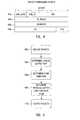
- the IPC 316receives a packet from the IFM 314.
- the IPC 316determines, at step 504, the logical output port corresponding to the input packet. This is done, in the preferred embodiment, by reading the ECI within the PFH that was inserted by the IFM 314 after a look-up function was completed.
- a flow identifieris determined for the packet.
- the flow identifieris a unique identifier for the data flow, preferably a TCP over IP stream.
- One characteristic that defines a data flowis the ECI in which the packet has been assigned.
- the data flowsare TCP streams which have specific start and end packets.
- the ECI of the packetis used in combination with specific TCP control fields to determine an index into a look-up table which will hold the flow identifier for the data flow.
- a new flow identifieris assigned in the look-up table to the particular data flow.
- Subsequent packets of the same flowprior to the end packet being received, are assigned the identical flow identifier.
- the flowis terminated and the corresponding flow identifier is removed from the look-up table so it can be reused by a new TCP flow.
- a flow identifieris also removed from the look-up table after a predetermined refresh period has expired that indicates that no further packets of that particular data flow are still to arrive.
- the next step within the load balancing functionis to determine the physical output port for the packet to traverse. If the packet is not the first of its data flow to be routed, the look-up table described above for the flow identifier would also indicate the physical output port for the particular packet. If the packet is the first packet of its data flow, the load balancing function determines the physical output port for its data flow and saves this determined physical output port selection within the look-up table for further packets of the same data flow to utilize. This determination of the physical output port is the key to the effectiveness of the load balancing function and can be done in numerous different ways.
- LBWis known for each available physical output port while the IR and the APS are generated, within the preferred embodiment, by statistical means described herein below.
- an exponentially weighted moving average (EWMA) techniqueis used that generates a continuously adjusting long term average of the number of packets per second being routed through the particular physical output port.
- EWMAexponentially weighted moving average
- an EWMA techniqueis also used that generates a long term average of the size of the packets being sent.
- the APSis calculated once using a large amount of data and subsequently is constant.
- this calculation of LABs for each physical output portis done within each IPC 316, though in an alternative embodiment these calculations are done in a central location within the router, such as the route controller, and the calculated LABs are bused to the individual IPF nodes.
- the size of the LABsindicate the availability of bandwidth for the incoming data flow and therefore, to make load balancing optimal, the current data flow is directed to the physical output port with the largest LAB.
- the packetis directed to a particular physical output port, according to the preferred embodiment, by writing to the RIU header attached to each of the packets of the particular data flow.
- the packetsare individually output from the IPC 316 and directed to the physical output port assigned to their corresponding data flow while maintaining the proper order.
- the key advantage of this load balancing of data flows among multiple physical links that comprise a supertrunkis that the user gains the advantages of using a supertrunk while not requiring the router that receives the packets of the data flow to re-order them due to differences in delays on the particular physical links.
- Alternative embodiments of the present inventionmay use different methods to determine the physical output port for a data flow compared to that disclosed herein for the preferred embodiment.
- One such alternative techniqueis disclosed within European patent application entitled “Apparatus and Method for Packet Switching with Supertrunking" by Almulhem et al, filed on the same day as the present invention and assigned to the assignee of the present invention.
- This method of determining physical output portsis specific to packet-level load balancing, but one skilled in the art would understand that it could be modified for flow-level load balancing as described herein.
- the data flows being input to the routercould be TCP flows or more specifically, IP streams that comprise a series of IP packets.
- the logical link for the data flowcan be read from the IP header within each individual packet.
Landscapes
- Engineering & Computer Science (AREA)
- Computer Networks & Wireless Communication (AREA)
- Signal Processing (AREA)
- Computer Security & Cryptography (AREA)
- Data Exchanges In Wide-Area Networks (AREA)
Abstract
Description
This invention relates generally to datarouting systems and more specifically to data routingsystems over multiple physical links.
The following paragraphs give definitions ofterms used throughout this document.
Physical link: a single point-to-point (PPP)serial transmission link between two nodes in the network(such as between two routers or between a router and ahost machine). The implementation of a serial link maytake various forms such as an optical fibre or awavelength segment on an optical fibre, among otheroptions.
Physical input/output port: the input/outputport of the router that supports one physical link.
Logical link: a point-to-point traffic pathbetween two routers that is composed of multiple physicallinks and appears from a routing point of view to be onelink.
Logical input/output port: the collection ofphysical input/output ports that support the physicallinks of a logical link.
Supertrunk: the aggregation of physical linksinto larger, logical links.
Transmission Control Protocol (TCP): a libraryof routines that applications can use when they needreliable network communications with another computer.TCP is responsible for verifying the correct delivery ofdata from client to server. It adds support to detect errors or lost data and to trigger reconstruction untilthe data is correctly and completely received.
Internet Protocol (IP): a library of routinesthat TCP calls on, but which is also available toapplications that do not use TCP. IP is responsible fortransporting packets of data from node to node. Itforwards each packet based on a four-byte destinationaddress (the IP address).
There has been an incredible increase in demandfor bandwidth within communication routing systems overthe past few years. This increase is particularlypronounced when considering the increase in datanetworking information transferred within these systemsdirectly associated with the expanding popularity of theInternet. Soon the traffic rates needed between routerpairs will be higher than the serial link transmissiontechnology available. Currently, the highesttransmission rate is 9.6 Gb/s, (on a single wavelength)but 2.4 Gb/s is much more commonly available. Purchasersof routers are already demanding 2.4 Gb/s links and it isexpected that within a short time, some routes willrequire multiple physical links.
There are other reasons why multi-link routesare attractive. In situations where routers areclustered in close physical proximity, the use ofmultiple links might allow the interconnect to bemultiple low cost links rather than single high costconnections. Another reason is that the application ofthe multi-link approach might also be a fast way toprovide higher rate ports on existing routers. Yetanother reason is that the use of multiple links allowsmore granularity of growth than the large steps in the transmission network and so may allow savings inbandwidth costs. Finally, another reason is thatmultiple links can allow for redundancy to cover linkfailure without requiring the spare link to cover thewhole bandwidth of the route.
When using multiple links between two routers,it is a requirement that the total bandwidth be usedefficiently. That is to say, the traffic offered must bespread over all available links, hereinafter referred toas load balancing. It would not be acceptable to haveone link under utilized while traffic is queued onanother. This suggests that packets from any source canbe delivered over any link to any destination. In fact,because of the bursting nature of the traffic, allocatinglinks statically to particular sources or destinationswould result in inefficient use of the total availablebandwidth.
When data traffic flows are spread overmultiple links, successive packets from a particular flow(for example, a TCP connection between two IP hosts) cantravel over different lengths and may arrive at thedestination out of order. The variability of delay canbe caused by different path lengths or differentcongestion levels on the paths, as well as the normalindeterminacy introduced by queuing and scheduling. TheTCP can accommodate some mis-ordering of packets, butthere is a problem if too much mis-ordering occurs on aconnection where the transmitter is using the fastretransmission protocol.
This mis-ordering of packets forces routersreceiving these packets to comprise a sorting functionthat is capable of re-ordering the packets into the proper order. This sorting function is likely to berelatively complex and cause a delay in the delivery ofdata flows to the destination. As well, if the receivingrouter is not setup for receiving packets of a singleflow along multiple physical links and therefore does nothave a sorting function, significant errors would occurwithin the transmission, delaying it further.
Therefore, a router is required that will allowthe use of multiple physical links for transmitting datatraffic without requiring re-ordering of packets or anyother special functions at the receiving router. Thisrouter must ensure that the order of the packets duringtransmission is maintained, but still allow for efficientload balancing between physical links.
According to a first aspect, the presentinvention provides a forwarding node capable of operationwithin a router that transfers digital data with aplurality of other routers within a packet routingsystem, the forwarding node comprising: a load balancingdevice that, when input with individual packets of a dataflow, reads a logical output port corresponding to thedata flow, assigns the data flow to a physical outputport within the logical output port based upon physicallink criteria, and outputs the individual packets totheir assigned physical output port.
According to a second aspect, the presentinvention provides a router capable of operation within apacket routing system that transfers digital data betweena plurality of the routers, the router comprising: aroute controller; a rotator space switch; at least onefirst forwarding node, coupled to both the route controller and the rotator space switch, comprising aload balancing device that, when input with individualpackets of a data flow, reads a logical output portcorresponding to the data flow, assigns the data flow toa physical output port within the logical output portbased upon physical link criteria, and outputs theindividual packets to their assigned physical outputport; and at least one second forwarding node, coupled toboth the route controller and the rotator space switch,that is arranged to operate as a physical output port foroutputting packets to at least one transmissionapparatus.
According to a third aspect, the presentinvention provides a packet routing system that transfersdigital data between at least one first router and atleast one second router, the packet routing systemcomprising: the first router comprising: a routecontroller; a rotator space switch; at least one firstforwarding node, coupled to both the route controller andthe rotator space switch, comprising a load balancingdevice that, when input with individual packets of a dataflow, reads a logical output port corresponding to thedata flow, assigns the data flow to a physical outputport within the logical output port based upon physicallink criteria, and outputs the individual packets totheir assigned physical output port; and at least onesecond forwarding node, coupled to both the routecontroller and the rotator space switch, that is arrangedto operate as a physical output port for outputtingpackets to at least one transmission apparatus; aplurality of transmission apparatuses coupled between thefirst and second routers; and the second router comprising: a second route controller; a second rotatorspace switch; at least one third forwarding node, coupledto both the second route controller and the secondrotator space switch, that is arranged to operate as aphysical input port for receiving packets from at leastone transmission apparatus; and at least one fourthforwarding node, coupled to both the second routecontroller and the second rotator space switch, that,when input with packets from the third forwarding node,outputs a data flow corresponding to the inputtedpackets.
According to a fourth aspect, the presentinvention provides in a packet routing system comprisinga plurality of routers, a method of transferring digitaldata between the routers comprising the steps of:inputting individual packets of a data flow into a firstrouter; reading a logical output port corresponding tothe data flow of the individual packets; assigning eachof the data flows to a physical output port within thelogical output port based upon physical link criteria;transmitting each of the packets, via their assignedphysical output ports, to a second router; and outputtinga data flow corresponding to the packets received at thesecond router.
The present invention therefore advantageouslyprovides an apparatus and method for increasing theefficiency of data communications.
Exemplary embodiments of the preferredembodiment of the present invention will now be describedwith reference to the following figures, in which:
FIGURES 1a and 1b illustrate example logicaland physical routing systems respectively that depictcommunication links from afirst router 102 to asecondrouter 104. Both the first and second routers 102,104are connected to a plurality of other communication links106,108 respectively. Within FIGURE 1a, alogical link 110 is shown coupled between the routers 102,104. Inthis particular example, the logical link is a 3.5 Gb/sconnection. FIGURE 1b illustrates a series ofphysicallinks 112, that make up a supertrunk, coupled between therouters 102,104 that together are equivalent to thelogical link 110. Thesupertrunk 112, in this example,comprises four physical links that when combined totalthe 3.5 Gb/s of thelogical link 110.
Each of thephysical links 112 depicted inFIGURE 1b may be implemented with a series of connectionswithin a series of different networks. Despite appearingwithin FIGURE 1b as being directly connected and physically local, it should be understood thatphysicallinks 112 are typically quite complex with the routers102,104 possibly a large distance from each other.
FIGURE 2 is a block diagram of a routing systembetween thefirst router 102 and thesecond router 104illustrating an example application of the preferredembodiment of the present invention. Each router102,104, according to the preferred embodiment, comprisesarotator space switch 202, aroute controller 204, and aplurality oftransport nodes 206. The routers 102,104depicted in FIGURE 2 each comprise two transport nodes,though this is not meant to limit the scope of thepresent invention. Therotator space switch 202 and theroute controller 204 are independently coupled to eachtransport node 206, although, within FIGURE 2, theroutecontroller 204 is only shown to be coupled to onetransport node 206 viasignal bus 208.
A person skilled in the art would understandthat the operation of therotator space switch 202 andtheroute controller 204 would be specific to aparticular company's implementation. For example, onesuch rotator space switch is disclosed in U.S. patent5,745,486 entitled "High Capacity ATM Switch" by Beshaiet al and assigned to the assignee of the presentinvention. No modifications are made in theroutecontroller 204 and therotator space switch 202 fromprior art devices within the preferred embodiment of thepresent invention.
Eachtransport node 206 comprises a pluralityof Internet Protocol Forwarding (IPF) nodes210,212,214,216,218. In FIGURE 2, eachtransport node 206 comprises four IPF nodes, though this is not meant to limit the scope of the present invention. In fact, therouters 102,104, in an alternative embodiment, do notcomprise transport nodes, but instead have a plurality ofIPF nodes, coupled independently to theroute controller 204 and therotator space switch 202, that are not withintransport nodes.
The IPF nodes, within the system depicted inFIGURE 2, include aninput IPF node 210, a plurality ofsupertrunkoutput IPF nodes 212 representing a singlelogical output port, a plurality of supertrunkinput IPFnodes 214 representing a single logical input port, anoutput IPF node 216, and a plurality ofother IPF nodes 218 which are unrelated to the description herein belowof an example application of the preferred embodiment ofthe present invention. Each IPF node, according to thepreferred embodiment, is identical. Hence, any one ofthe IPF nodes may, in practice, be an input IPF node, asupertrunk output IPF node, a supertrunk input IPF node,or an output IPF node.
As depicted in FIGURE 2, theinput IPF node 210is within a transport node of thefirst router 102 and isinput with a TCP input signal (TCPIN) vialine 220. Theinput IPF node 210 is coupled to therotator space switch 202 of thefirst router 102 vialine 222.
The plurality of supertrunkoutput IPF nodes 212 are spread across thetransport nodes 206 of thefirst router 102. In this example, there are foursupertrunkoutput IPF nodes 212 with two in eachtransport node 206 of thefirst router 102, though otherconfigurations are possible. The supertrunkoutput IPFnodes 212 are each independently coupled to therotatorspace switch 202 of thefirst router 102 vialines 224 and, via thesupertrunk 112, to thesecond router 104.Thesupertrunk 112 comprisesphysical links firstrouter 102 and the supertrunk input IPF nodes 214 (thephysical input ports) within thesecond router 104.
The supertrunkinput IPF nodes 214 are spreadacross the twotransport nodes 206 of thesecond router 104. In this example, there are four supertrunkinputIPF nodes 214, three in onetransport node 206 and one inthe other. This illustrated configuration is not meantto limit the scope of the present invention and it shouldbe recognized that the number of supertrunkinput IPFnodes 214 does not have to equal the number of supertrunkoutput IPF nodes 212. A single supertrunkoutput IPFnode 212 could be coupled via a plurality of physicallinks to a plurality of supertrunkinput IPF nodes 214and a plurality of supertrunkoutput IPF nodes 212 couldbe coupled to the same supertrunkinput IPF node 214.Each of the supertrunkinput IPF nodes 214 areindependently coupled to therotator space switch 202 ofthesecond router 104 vialines 228.
Theoutput IPF node 216 is within thetransportnode 206 of thesecond router 104 that has only onesupertrunkinput IPF node 214, but it is recognized thattheoutput IPF node 216 could be located in anytransportnode 206 of thesecond router 104. Theoutput IPF node 216 is coupled to therotator space switch 202 of thesecond router 104 vialine 230 and outputs a TCP outputsignal (TCPOUT) via line 232.
Theother IPF nodes 218 are simply shown withinFIGURE 2 to illustrate that other operations are being performed concurrently with the example applicationdescribed herein below. Each of theother IPF nodes 218is coupled to the rotator space switches 202 of therespective router 102,104 vialines 234.
The supertrunking operation of the routingsystem of FIGURE 2, according to the preferred embodimentof the present invention, is now described by example.The TCPIN, which is a series of packets that comprise adata flow (a TCP over IP stream in the preferredembodiment), is input to theinput IPF node 210 packet bypacket. Theinput IPF node 210 attaches a PacketForwarding Header (PFH), described in detail hereinbelow, and a Rotator Information Unit (RIU) header toeach packet. The RIU header comprises a physical outputport indicator that corresponds to a particularphysicaloutput port 212 determined, with use of a load balancingfunction also described in detail herein below, for theparticular data flow in which the packet is comprised.
Each data flow, split into individual packetswith their respective PFH and RIU header, is thenforwarded to its respective supertrunkoutput IPF node 212 via theline 222, therotator space switch 202 of thefirst router 102, and thelines 224. The supertrunkoutput IPF node 212 when sequentially input with thepackets of a data flow then proceeds to remove the PFHand RIU header from each of the packets and outputs thepackets of the data flow to aphysical link 112 betweenthe first and second routers 102,104.
The data flows are received packet by packet atthe supertrunkinput IPF nodes 214 and forwarded to theoutput IPF node 216 via thelines 228, therotator spaceswitch 202 of thesecond router 104, and theline 230. Theoutput IPF node 216 outputs TCPOUT which, in thiscase, is a series of packets that comprise a data flowconsistent with the data flow of TCPIN.
The IPF nodes of FIGURE 2 according to thepreferred embodiment of the present invention are nowdescribed in detail with reference to FIGURE 3. In thispreferred embodiment, all of the IPF nodes are identicaland therefore, all of the IPF nodes contain the loadbalancing function. As depicted in FIGURE 3, each IPFnode comprises aningress block 302, anegress block 304,a Space Switch Interface (SSI) 306, an Embedded ProcessorInterface (EPI) 308, and a Router Monitor (RMON) 310.Theingress block 302 comprises an Ingress ConvergenceProcessor (ICP) 312 coupled in series with an IngressFilter and Mapper (IFM) 314, and an Ingress PortController (IPC) 316 further coupled to theSSI 306. Theegress block 304 comprises an Egress Packet Queuer (EPQ)318 coupled to theSSI 306 and further coupled in serieswith an Egress Packet Scheduler (EPS) 320, and an EgressConvergence Processor (ECP) 322. It is noted thataccording to the preferred embodiment, all of thesecomponents are discrete devices, though in alternativeembodiments some or all of these components could becombined or implemented within software.
TheEPI 308, in the preferred embodiment, iscoupled to the components of both the ingress and egressblocks 302,304 along with theSSI 306 and theRMON 310.TheRMON 310 is further coupled to at least one componentin each of the ingress and egress blocks 302,304. In thepreferred embodiment, theRMON 310 is coupled to theoutputs of theIPC 316 and theEPS 320. TheEPI 308 isthe local processor for the IPF node that performs numerous processor related functions. TheRMON 310, onthe other hand, is utilized as a central point for allcounters within the IPF node.
The following is a simplified description ofthe operation within the devices of the IPF node duringingress and egress functions according to the preferredembodiment of the present invention. It is noted thatthe devices of FIGURE 3, with the exception of theIPC 316, are not modified in the preferred embodiment of thepresent invention and one skilled in the art wouldunderstand their operations.
During the receiving of incoming data packetsof a data flow, theICP 312 terminates the ingressphysical and link layer interfaces, verifies the linklayer, IP headers, and formatting, maps the incomingpackets to a Receive Context Identifier (RCI) that is ageneric tag to uniquely identify the logical interfacethat a packet arrived on, and encapsulates each of theindividual packets with a PFH. As described hereinbelow, not all the contents of the PFH are inserted bytheICP 312, but bytes are reserved for the entire PFH.
The PFH, with reference to FIGURE 4, comprisesfour 32 bit words. Thefirst word 402 comprises a 4 bitStart Of Packet Offset (SOP_OFFS) signal that indicatesthe position of the first word of the packet to be sentto the link layer for segmentation, an 8 bit VirtualPrivate Network Identifier (VPN_ID) signal thatidentifies the virtual private network or virtual routerinterface that the packet arrived on, and the 20 bit RCI.Thesecond word 404 comprises 32 bits of PacketForwarding Flags (PF_FLAGS) that are a collection ofgeneric status and control flags. Thethird word 406 comprises 32 reserved bits not utilized in the preferredembodiment of the present invention. Thefourth word 408comprises a 24 bit Egress Context Identifier (ECI) thatis the result of a forwarding look-up function and issomewhat analogous to a flow identifier, and an 8 bit PFHIntegrity Check (CRC). The contents of thefirst word 402 of the PFH are determined and inserted by theICP 312while the contents of thesecond word 404 can be set ormodified by each of the blocks of the IPF node. Thefourth word 408 is reserved space by theICP 312, but thecontents of thefourth word 408 are determined andinserted by another device as will described hereinbelow.
The outputted packets from theICP 312 areinput to theIFM 314 which maps the incoming packets tothe logical ECI, inserts the ECI into the PFH, andfilters packets based on a configured policy. TheIPC 316 then receives the packets, performs the loadbalancing function, as will be described herein below,and encapsulates each of the packets in a RIU headerwhich maps the packet to physical output ports determinedby the load balancing function. Within the presentinvention, all the packets of a particular data flow aremapped to the same physical output port.
Subsequently, the packets are sequentiallyinput to theSSI 306 which is the interface between therotator space switch 202 and the particular IPF of FIGURE2. TheSSI 306 then outputs the packets through therotator space switch to the particular physical outputport chosen by the load balancing function for theparticular data flow.
At the physical output port, the packet is input to theSSI 306 and forwarded, via theEPQ 318 andtheEPS 320, to theECP 322. TheECP 322 subsequentlyremoves the PFH and RIU header from each of the packetsand forwards the packets, via a physical link, to aphysical input port; that being an IPF node within therouter of the destination output IPF node.
Within the preferred embodiment of the presentinvention, the packets are received at the physical inputport and input to thecorresponding ICP 312. TheICP 312and theIFM 314 perform similar functions as describedherein above, such as attaching a PFH to each of thepackets, and sequentially forwarding the packets to theIPC 316. The load balancing function within theIPC 316is not performed on the packets of the data flow sincethe output IPF node for the flow is an IPF node withinthe same router. TheIPC 316 simply attaches an RIUheader, which maps the packet to its output IPF node, toeach of the packets and forwards them, via theSSI 306and the rotator space switch, to theSSI 306 of theoutput IPF node.
The packet is forwarded by theSSI 306 of theoutput IPF node to theEPQ 318. TheEPQ 318 reassemblespacket segments and notifies theEPS 320 of theavailability of packets to be scheduled. Since allpackets of a particular data flow are routed via the samephysical output port, the packets remain in the properorder. Hence, each packet that is reassembled becomesavailable for scheduling without the need for a re-orderingfunction. Subsequently, theEPS 320 maps thepackets to scheduling queues and outputs the packets totheECP 322 which removes the PFH and RIU header andperforms L2 and PHY encapsulation functions as required.
The detailed description of the load balancingfunction, according to the preferred embodiment of thepresent invention, performed within theIPC 316 is nowdescribed with reference to FIGURE 5. Firstly, asdepicted atstep 502, theIPC 316 receives a packet fromtheIFM 314. Next, theIPC 316 determines, atstep 504,the logical output port corresponding to the inputpacket. This is done, in the preferred embodiment, byreading the ECI within the PFH that was inserted by theIFM 314 after a look-up function was completed.
Subsequently atstep 506, a flow identifier isdetermined for the packet. The flow identifier is aunique identifier for the data flow, preferably a TCPover IP stream. One characteristic that defines a dataflow is the ECI in which the packet has been assigned.In the preferred embodiment, the data flows are TCPstreams which have specific start and end packets. TheECI of the packet is used in combination with specificTCP control fields to determine an index into a look-uptable which will hold the flow identifier for the dataflow. After the arrival of a start packet for aparticular data flow, a new flow identifier is assignedin the look-up table to the particular data flow.Subsequent packets of the same flow, prior to the endpacket being received, are assigned the identical flowidentifier. When the end packet of the particular TCPflow is received, the flow is terminated and thecorresponding flow identifier is removed from the look-uptable so it can be reused by a new TCP flow. In thepreferred embodiment, a flow identifier is also removedfrom the look-up table after a predetermined refreshperiod has expired that indicates that no further packets of that particular data flow are still to arrive.
The next step within the load balancingfunction, as depicted atstep 508, is to determine thephysical output port for the packet to traverse. If thepacket is not the first of its data flow to be routed,the look-up table described above for the flow identifierwould also indicate the physical output port for theparticular packet. If the packet is the first packet ofits data flow, the load balancing function determines thephysical output port for its data flow and saves thisdetermined physical output port selection within thelook-up table for further packets of the same data flowto utilize. This determination of the physical outputport is the key to the effectiveness of the loadbalancing function and can be done in numerous differentways.
According to the preferred embodiment of thepresent invention, a Link Available Bandwidth (LAB) inunits of bytes/sec is generated within the load balancingfunction for each of the available physical output ports.This is determined with use of the following formula:LAB = (LBW) - (IR) * (APS) where, LBW is the Link Bandwidth in units of bytes/sec,IR is the Input Rate in units of packets/sec, and APS isthe Average Packet Size. The LBW is known for eachavailable physical output port while the IR and the APSare generated, within the preferred embodiment, bystatistical means described herein below.
To calculate, according to the preferredembodiment, the IR of a particular physical output port,an exponentially weighted moving average (EWMA) techniqueis used that generates a continuously adjusting long term average of the number of packets per second being routedthrough the particular physical output port. Tocalculate, according to the preferred embodiment, the APSfor all the physical output ports, an EWMA technique isalso used that generates a long term average of the sizeof the packets being sent. In an alternative embodiment,the APS is calculated once using a large amount of dataand subsequently is constant.
In the preferred embodiment, this calculationof LABs for each physical output port is done within eachIPC 316, though in an alternative embodiment thesecalculations are done in a central location within therouter, such as the route controller, and the calculatedLABs are bused to the individual IPF nodes.
The size of the LABs indicate the availabilityof bandwidth for the incoming data flow and therefore, tomake load balancing optimal, the current data flow isdirected to the physical output port with the largestLAB. The packet is directed to a particular physicaloutput port, according to the preferred embodiment, bywriting to the RIU header attached to each of the packetsof the particular data flow. Finally, atstep 510, thepackets are individually output from theIPC 316 anddirected to the physical output port assigned to theircorresponding data flow while maintaining the properorder.
The key advantage of this load balancing ofdata flows among multiple physical links that comprise asupertrunk is that the user gains the advantages of usinga supertrunk while not requiring the router that receivesthe packets of the data flow to re-order them due todifferences in delays on the particular physical links. This means that traditional routers without supertrunktechnology can be utilized as receiving routers accordingto the preferred embodiment of the present invention withno special treatment required for the supertrunkedpackets compared to regular non-supertrunked packets.
Alternative embodiments of the presentinvention may use different methods to determine thephysical output port for a data flow compared to thatdisclosed herein for the preferred embodiment. One suchalternative technique is disclosed within European patentapplication entitled "Apparatus and Method for PacketSwitching with Supertrunking" by Almulhem et al, filed onthe same day as the present invention and assigned to theassignee of the present invention. This method ofdetermining physical output ports is specific to packet-levelload balancing, but one skilled in the art wouldunderstand that it could be modified for flow-level loadbalancing as described herein.
One skilled in the art would recognize that thedata flows being input to the router could be TCP flowsor more specifically, IP streams that comprise a seriesof IP packets. In this case, the logical link for thedata flow can be read from the IP header within eachindividual packet.
Persons skilled in the art will appreciate thatthere are alternative implementations and modificationspossible to use an apparatus similar to that describedabove to provide a routing system over multiple physicallinks, and that the above implementation is only anillustration of this embodiment of the invention. Thescope of the invention, therefore, is only to be limitedby the claims appended hereto.
Claims (20)
- A forwarding node capable of operation within arouter that transfers digital data with a plurality ofother routers within a packet routing system, theforwarding node comprising:
a load balancing device that, when input withindividual packets of a data flow, reads a logical outputport corresponding to the data flow, assigns the dataflow to a physical output port within the logical outputport based upon physical link criteria, and outputs theindividual packets to their assigned physical outputport. - The forwarding node according to claim 1,wherein the load balancing device assigns the data flowto a physical output port by determining a physicaloutput port for the data flow and encapsulating each ofthe packets of the data flow in a routing header thatcomprises a physical output port identifier; and
wherein the forwarding node further comprises apacket receiving device that, when input with anencapsulated packet, removes the routing header from thepacket and outputs the packet to a transmissionapparatus. - A router capable of operation within a packetrouting system that transfers digital data between aplurality of the routers, the router comprising:a route controller;a rotator space switch;at least one first forwarding node, coupled toboth the route controller and the rotator space switch, comprising a load balancing device that, when input withindividual packets of a data flow, reads a logical outputport corresponding to the data flow, assigns the dataflow to a physical output port within the logical outputport based upon physical link criteria, and outputs theindividual packets to their assigned physical outputport; andat least one second forwarding node, coupled toboth the route controller and the rotator space switch,that is arranged to operate as a physical output port foroutputting packets to at least one transmissionapparatus.
- The router according to claim 3, wherein thefirst and second forwarding nodes are the same forwardingnode.
- The router according to claim 3 or claim 4,wherein the load balancing device assigns the data flowto a physical output port by determining a physicaloutput port for the data flow and encapsulating each ofthe packets of the data flow in a routing header thatcomprises a physical output port identifier; and
wherein the second forwarding node comprises apacket receiving device that, when input with anencapsulated packet, removes the routing header from thepacket. - The router according to claim 5 or theforwarding node of claim 2, wherein the routing headercomprises a rotator information unit header; and
wherein the rotator information unit header comprises the physical output port identifier. - The router according to claim 3 or claim 4 orthe forwarding node of claim 1 or claim 2, wherein, whena first packet of a data flow is detected, the loadbalancing device determines a physical output port toassign to the particular packet and to store in a look-uptable for the corresponding data flow and, when a packetis not the first packet of a data flow, the packet isassigned the physical output port corresponding to itsdata flow with use of the look-up table.
- The router or the forwarding node of claim 7,wherein the load balancing device further encapsulatesthe packets in a routing header that comprises a packetforwarding header and a rotator information unit header;wherein the forwarding node further comprises apacket receiving device that, when input with anencapsulated packet, removes the routing header from thepacket and outputs the packet to a transmissionapparatus;wherein the packet forwarding header comprisesan egress context identifier and the rotator informationunit header comprises a physical output port identifier.
- The router or the forwarding node of claim 8,wherein the egress context identifier is determined foreach packet with use of a second look-up table.
- The router or forwarding node of claims 7, 8 or9, wherein the load balancing device further determines aflow identifier for each packet; and
wherein, when a first packet of a data flow isdetected, the load balancing device generates a new flowidentifier to assign to the particular packet and tostore in the look-up table for the corresponding dataflow and, when a packet is not the first packet of a dataflow, the packet is assigned the flow identifiercorresponding to its data flow with use of the look-uptable. - The forwarding node according to any one ofclaims 1,2 or 6 to 10, wherein the physical link criteriaare link available bandwidth (LAB) factors calculated foreach of the available physical output ports, each of theLAB factors for a particular physical output portequalling a link rate multiplied by an average packetsize, subtracted from a total available bandwidth.
- The forwarding node according to claim 11,wherein the link rate is determined by calculating thenumber of packets routed via the particular physicaloutput port during a predetermined amount of time.
- The forwarding node according to claim 11,wherein the link rate is calculated with use of anexponentially weighted moving average technique.
- The forwarding node according to any one ofclaims 11 to 13, wherein the average packet size iscalculated with use of an exponentially weighted movingaverage technique.
- The forwarding node according to any one of claims 11 to 14, wherein the load balancing deviceassigns each of the individual packets of the data flowto the physical output port that had the highest LABfactor at the arrival time of the first packet of thedata flow.
- The forwarding node according to any one ofclaims 1, 2 or 6 to 15, wherein the data flow is aTransmission Control Protocol (TCP) flow, and one of:
an Internet Protocol (IP) stream and theindividual packets of the data flow are IP packets. - The forwarding node according to any one ofclaims 1, 2 or 6 to 16 comprising an ingress block thatis arranged to input packets from a transmission deviceand comprises the load balancing device, an egress blockthat is arranged to output packets to the transmissiondevice, and a switch interface, coupled to both theingress and egress blocks, that is arranged to be coupledto a switch apparatus.
- The forwarding node according to claim 17,wherein the ingress block comprises an ingress processorcoupled in series with an ingress filter and mapper andan ingress port controller that is further coupled to theswitch interface, and the egress block comprises anegress queuer coupled to the switch interface and furthercoupled in series with an egress scheduler and an egressprocessor; and
wherein the ingress port controller comprisesthe load balancing device. - A packet routing system that transfers digitaldata between at least one first router and at least onesecond router, the packet routing system comprising:the first router comprising: a routecontroller; a rotator space switch; at least one firstforwarding node, coupled to both the route controller andthe rotator space switch, comprising a load balancingdevice that, when input with individual packets of a dataflow, reads a logical output port corresponding to thedata flow, assigns the data flow to a physical outputport within the logical output port based upon physicallink criteria, and outputs the individual packets totheir assigned physical output port; and at least onesecond forwarding node, coupled to both the routecontroller and the rotator space switch, that is arrangedto operate as a physical output port for outputtingpackets to at least one transmission apparatus;a plurality of transmission apparatuses coupledbetween the first and second routers; andthe second router comprising: a second routecontroller; a second rotator space switch; at least onethird forwarding node, coupled to both the second routecontroller and the second rotator space switch, that isarranged to operate as a physical input port forreceiving packets from at least one transmissionapparatus; and at least one fourth forwarding node,coupled to both the second route controller and thesecond rotator space switch, that, when input withpackets from the third forwarding node, outputs a dataflow corresponding to the inputted packets.
- A method of transferring digital data between aplurality of routers in a packet routing system,comprising the steps of:inputting individual packets of a data flowinto a first router;reading a logical output port corresponding tothe data flow of the individual packets;assigning each of the data flows to a physicaloutput port within the logical output port based uponphysical link criteria;transmitting each of the packets, via theirassigned physical output ports, to a second router; andoutputting a data flow corresponding to thepackets received at the second router.
Applications Claiming Priority (2)
| Application Number | Priority Date | Filing Date | Title |
|---|---|---|---|
| US09/215,376US6510135B1 (en) | 1998-12-18 | 1998-12-18 | Flow-level demultiplexing within routers |
| US215376 | 1998-12-18 |
Publications (2)
| Publication Number | Publication Date |
|---|---|
| EP1011227A2true EP1011227A2 (en) | 2000-06-21 |
| EP1011227A3 EP1011227A3 (en) | 2003-02-05 |
Family
ID=22802746
Family Applications (1)
| Application Number | Title | Priority Date | Filing Date |
|---|---|---|---|
| EP99309743AWithdrawnEP1011227A3 (en) | 1998-12-18 | 1999-12-03 | Apparatus and method for flow-level demultiplexing |
Country Status (3)
| Country | Link |
|---|---|
| US (1) | US6510135B1 (en) |
| EP (1) | EP1011227A3 (en) |
| CA (1) | CA2285851A1 (en) |
Cited By (4)
| Publication number | Priority date | Publication date | Assignee | Title |
|---|---|---|---|---|
| WO2003067834A1 (en)* | 2002-02-01 | 2003-08-14 | Fujitsu Limited | Forwarding packets to aggregated links using distributed ingress card processing |
| WO2003061194A3 (en)* | 2001-12-26 | 2003-09-18 | Tropic Networks Inc | Multi-constraint routine system and method |
| US6925061B2 (en) | 2001-12-26 | 2005-08-02 | Tropic Network Inc. | Multi-constraint routing system and method |
| EP2730067A4 (en)* | 2011-07-08 | 2015-01-14 | Ericsson Telefon Ab L M | Method and apparatus for load balancing |
Families Citing this family (73)
| Publication number | Priority date | Publication date | Assignee | Title |
|---|---|---|---|---|
| JP3409726B2 (en)* | 1999-02-26 | 2003-05-26 | 日本電気株式会社 | Transfer destination decision processing device |
| US7058728B1 (en)* | 1999-10-29 | 2006-06-06 | Nokia Corporation | Method and apparatus for initiating compression of headers of packets and refreshing the context related to the packets |
| US8380854B2 (en)* | 2000-03-21 | 2013-02-19 | F5 Networks, Inc. | Simplified method for processing multiple connections from the same client |
| US7343413B2 (en) | 2000-03-21 | 2008-03-11 | F5 Networks, Inc. | Method and system for optimizing a network by independently scaling control segments and data flow |
| US6928482B1 (en)* | 2000-06-29 | 2005-08-09 | Cisco Technology, Inc. | Method and apparatus for scalable process flow load balancing of a multiplicity of parallel packet processors in a digital communication network |
| US7272116B1 (en) | 2000-06-30 | 2007-09-18 | Cisco Technology, Inc. | Protocol for automatic traffic provisioning in 4-fiber BLSR SONET networks |
| JP3654168B2 (en)* | 2000-09-28 | 2005-06-02 | 日本電気株式会社 | Interface identification device, interface identification method, and MPLS-VPN service network |
| US7068654B1 (en)* | 2001-04-18 | 2006-06-27 | 3Com Corporation | System and method for providing masquerading using a multiprotocol label switching |
| US7792113B1 (en) | 2002-10-21 | 2010-09-07 | Cisco Technology, Inc. | Method and system for policy-based forwarding |
| US8687628B2 (en)* | 2006-03-16 | 2014-04-01 | Rockstar Consortium USLP | Scalable balanced switches |
| US7539133B2 (en)* | 2006-03-23 | 2009-05-26 | Alcatel-Lucent Usa Inc. | Method and apparatus for preventing congestion in load-balancing networks |
| ATE502464T1 (en)* | 2007-07-06 | 2011-04-15 | Alcatel Lucent | METHOD FOR ROUTING A TRAFFIC FLOW IN A RADIO ACCESS NETWORK AND NODES FOR IMPLEMENTING SUCH METHOD |
| US8045563B2 (en)* | 2007-12-27 | 2011-10-25 | Cellco Partnership | Dynamically adjusted credit based round robin scheduler |
| US8806053B1 (en) | 2008-04-29 | 2014-08-12 | F5 Networks, Inc. | Methods and systems for optimizing network traffic using preemptive acknowledgment signals |
| US8566444B1 (en) | 2008-10-30 | 2013-10-22 | F5 Networks, Inc. | Methods and system for simultaneous multiple rules checking |
| EP2453612B1 (en)* | 2009-07-07 | 2014-12-03 | Panasonic Corporation | Bus control device |
| US8264966B1 (en)* | 2009-09-04 | 2012-09-11 | Sprint Communications Company L.P. | Overload management on backhaul links based on packet loss on RF links |
| US10157280B2 (en) | 2009-09-23 | 2018-12-18 | F5 Networks, Inc. | System and method for identifying security breach attempts of a website |
| US8238250B2 (en)* | 2009-10-16 | 2012-08-07 | Hei Tao Fung | QoS-aware flow-based dynamic load balancing for link aggregation |
| US10721269B1 (en) | 2009-11-06 | 2020-07-21 | F5 Networks, Inc. | Methods and system for returning requests with javascript for clients before passing a request to a server |
| US8868961B1 (en) | 2009-11-06 | 2014-10-21 | F5 Networks, Inc. | Methods for acquiring hyper transport timing and devices thereof |
| US9313047B2 (en) | 2009-11-06 | 2016-04-12 | F5 Networks, Inc. | Handling high throughput and low latency network data packets in a traffic management device |
| US8654771B1 (en) | 2010-02-03 | 2014-02-18 | Sprint Communications Company L.P. | Efficient transfer of packets over multiple backhaul links |
| US9141625B1 (en) | 2010-06-22 | 2015-09-22 | F5 Networks, Inc. | Methods for preserving flow state during virtual machine migration and devices thereof |
| US10015286B1 (en) | 2010-06-23 | 2018-07-03 | F5 Networks, Inc. | System and method for proxying HTTP single sign on across network domains |
| US9680750B2 (en) | 2010-07-06 | 2017-06-13 | Nicira, Inc. | Use of tunnels to hide network addresses |
| US8837493B2 (en)* | 2010-07-06 | 2014-09-16 | Nicira, Inc. | Distributed network control apparatus and method |
| US8908545B1 (en) | 2010-07-08 | 2014-12-09 | F5 Networks, Inc. | System and method for handling TCP performance in network access with driver initiated application tunnel |
| US8347100B1 (en) | 2010-07-14 | 2013-01-01 | F5 Networks, Inc. | Methods for DNSSEC proxying and deployment amelioration and systems thereof |
| US9083760B1 (en) | 2010-08-09 | 2015-07-14 | F5 Networks, Inc. | Dynamic cloning and reservation of detached idle connections |
| US8630174B1 (en) | 2010-09-14 | 2014-01-14 | F5 Networks, Inc. | System and method for post shaping TCP packetization |
| US8463909B1 (en) | 2010-09-15 | 2013-06-11 | F5 Networks, Inc. | Systems and methods for managing server resources |
| US8886981B1 (en) | 2010-09-15 | 2014-11-11 | F5 Networks, Inc. | Systems and methods for idle driven scheduling |
| US8804504B1 (en) | 2010-09-16 | 2014-08-12 | F5 Networks, Inc. | System and method for reducing CPU load in processing PPP packets on a SSL-VPN tunneling device |
| WO2012058643A2 (en) | 2010-10-29 | 2012-05-03 | F5 Networks, Inc. | System and method for on the fly protocol conversion in obtaining policy enforcement information |
| US8959571B2 (en) | 2010-10-29 | 2015-02-17 | F5 Networks, Inc. | Automated policy builder |
| US8627467B2 (en) | 2011-01-14 | 2014-01-07 | F5 Networks, Inc. | System and method for selectively storing web objects in a cache memory based on policy decisions |
| US10135831B2 (en) | 2011-01-28 | 2018-11-20 | F5 Networks, Inc. | System and method for combining an access control system with a traffic management system |
| US9246819B1 (en) | 2011-06-20 | 2016-01-26 | F5 Networks, Inc. | System and method for performing message-based load balancing |
| US9270766B2 (en) | 2011-12-30 | 2016-02-23 | F5 Networks, Inc. | Methods for identifying network traffic characteristics to correlate and manage one or more subsequent flows and devices thereof |
| US10230566B1 (en) | 2012-02-17 | 2019-03-12 | F5 Networks, Inc. | Methods for dynamically constructing a service principal name and devices thereof |
| US9172753B1 (en) | 2012-02-20 | 2015-10-27 | F5 Networks, Inc. | Methods for optimizing HTTP header based authentication and devices thereof |
| US9231879B1 (en) | 2012-02-20 | 2016-01-05 | F5 Networks, Inc. | Methods for policy-based network traffic queue management and devices thereof |
| WO2013163648A2 (en) | 2012-04-27 | 2013-10-31 | F5 Networks, Inc. | Methods for optimizing service of content requests and devices thereof |
| JPWO2013168427A1 (en)* | 2012-05-11 | 2016-01-07 | パナソニックIpマネジメント株式会社 | Bus control system and network interface |
| US10375155B1 (en) | 2013-02-19 | 2019-08-06 | F5 Networks, Inc. | System and method for achieving hardware acceleration for asymmetric flow connections |
| US9584488B2 (en)* | 2013-08-09 | 2017-02-28 | Introspective Power, Inc. | Data encryption cipher using rotating ports |
| US10187317B1 (en) | 2013-11-15 | 2019-01-22 | F5 Networks, Inc. | Methods for traffic rate control and devices thereof |
| US10015143B1 (en) | 2014-06-05 | 2018-07-03 | F5 Networks, Inc. | Methods for securing one or more license entitlement grants and devices thereof |
| US11838851B1 (en) | 2014-07-15 | 2023-12-05 | F5, Inc. | Methods for managing L7 traffic classification and devices thereof |
| US10122630B1 (en) | 2014-08-15 | 2018-11-06 | F5 Networks, Inc. | Methods for network traffic presteering and devices thereof |
| US10182013B1 (en) | 2014-12-01 | 2019-01-15 | F5 Networks, Inc. | Methods for managing progressive image delivery and devices thereof |
| US11895138B1 (en) | 2015-02-02 | 2024-02-06 | F5, Inc. | Methods for improving web scanner accuracy and devices thereof |
| US10834065B1 (en) | 2015-03-31 | 2020-11-10 | F5 Networks, Inc. | Methods for SSL protected NTLM re-authentication and devices thereof |
| US10505818B1 (en) | 2015-05-05 | 2019-12-10 | F5 Networks. Inc. | Methods for analyzing and load balancing based on server health and devices thereof |
| US11350254B1 (en) | 2015-05-05 | 2022-05-31 | F5, Inc. | Methods for enforcing compliance policies and devices thereof |
| US11757946B1 (en) | 2015-12-22 | 2023-09-12 | F5, Inc. | Methods for analyzing network traffic and enforcing network policies and devices thereof |
| US10404698B1 (en) | 2016-01-15 | 2019-09-03 | F5 Networks, Inc. | Methods for adaptive organization of web application access points in webtops and devices thereof |
| US11178150B1 (en) | 2016-01-20 | 2021-11-16 | F5 Networks, Inc. | Methods for enforcing access control list based on managed application and devices thereof |
| US10797888B1 (en) | 2016-01-20 | 2020-10-06 | F5 Networks, Inc. | Methods for secured SCEP enrollment for client devices and devices thereof |
| US10791088B1 (en) | 2016-06-17 | 2020-09-29 | F5 Networks, Inc. | Methods for disaggregating subscribers via DHCP address translation and devices thereof |
| US11063758B1 (en) | 2016-11-01 | 2021-07-13 | F5 Networks, Inc. | Methods for facilitating cipher selection and devices thereof |
| US10505792B1 (en) | 2016-11-02 | 2019-12-10 | F5 Networks, Inc. | Methods for facilitating network traffic analytics and devices thereof |
| US11496438B1 (en) | 2017-02-07 | 2022-11-08 | F5, Inc. | Methods for improved network security using asymmetric traffic delivery and devices thereof |
| US10791119B1 (en) | 2017-03-14 | 2020-09-29 | F5 Networks, Inc. | Methods for temporal password injection and devices thereof |
| US10812266B1 (en) | 2017-03-17 | 2020-10-20 | F5 Networks, Inc. | Methods for managing security tokens based on security violations and devices thereof |
| US10931662B1 (en) | 2017-04-10 | 2021-02-23 | F5 Networks, Inc. | Methods for ephemeral authentication screening and devices thereof |
| US10972453B1 (en) | 2017-05-03 | 2021-04-06 | F5 Networks, Inc. | Methods for token refreshment based on single sign-on (SSO) for federated identity environments and devices thereof |
| US11122042B1 (en) | 2017-05-12 | 2021-09-14 | F5 Networks, Inc. | Methods for dynamically managing user access control and devices thereof |
| US11343237B1 (en) | 2017-05-12 | 2022-05-24 | F5, Inc. | Methods for managing a federated identity environment using security and access control data and devices thereof |
| US11122083B1 (en) | 2017-09-08 | 2021-09-14 | F5 Networks, Inc. | Methods for managing network connections based on DNS data and network policies and devices thereof |
| US11658995B1 (en) | 2018-03-20 | 2023-05-23 | F5, Inc. | Methods for dynamically mitigating network attacks and devices thereof |
| US11044200B1 (en) | 2018-07-06 | 2021-06-22 | F5 Networks, Inc. | Methods for service stitching using a packet header and devices thereof |
Family Cites Families (6)
| Publication number | Priority date | Publication date | Assignee | Title |
|---|---|---|---|---|
| US5168492A (en)* | 1991-04-11 | 1992-12-01 | Northern Telecom Limited | Rotating-access ATM-STM packet switch |
| JPH07170264A (en)* | 1993-12-14 | 1995-07-04 | Nec Corp | Constitution system for digital speech path network |
| US5745486A (en) | 1995-10-26 | 1998-04-28 | Northern Telecom Limited | High capacity ATM switch |
| US6111858A (en)* | 1997-02-18 | 2000-08-29 | Virata Limited | Proxy-controlled ATM subnetwork |
| KR100211123B1 (en)* | 1997-05-23 | 1999-07-15 | 윤종용 | Multistage interconnection network for high speed packet switching |
| US6122274A (en)* | 1997-11-16 | 2000-09-19 | Sanjeev Kumar | ATM switching system with decentralized pipeline control and plural memory modules for very high capacity data switching |
- 1998
- 1998-12-18USUS09/215,376patent/US6510135B1/ennot_activeExpired - Lifetime
- 1999
- 1999-10-13CACA002285851Apatent/CA2285851A1/ennot_activeAbandoned
- 1999-12-03EPEP99309743Apatent/EP1011227A3/ennot_activeWithdrawn
Cited By (8)
| Publication number | Priority date | Publication date | Assignee | Title |
|---|---|---|---|---|
| WO2003061194A3 (en)* | 2001-12-26 | 2003-09-18 | Tropic Networks Inc | Multi-constraint routine system and method |
| US6925061B2 (en) | 2001-12-26 | 2005-08-02 | Tropic Network Inc. | Multi-constraint routing system and method |
| US7187652B2 (en) | 2001-12-26 | 2007-03-06 | Tropic Networks Inc. | Multi-constraint routing system and method |
| WO2003067834A1 (en)* | 2002-02-01 | 2003-08-14 | Fujitsu Limited | Forwarding packets to aggregated links using distributed ingress card processing |
| US6973082B2 (en) | 2002-02-01 | 2005-12-06 | Fujitsu Limited | Forwarding packets to aggregated links using distributed ingress card processing |
| US7551616B2 (en) | 2002-02-01 | 2009-06-23 | Fujitsu Limited | Forwarding packets to aggregated links using distributed ingress card processing |
| EP2730067A4 (en)* | 2011-07-08 | 2015-01-14 | Ericsson Telefon Ab L M | Method and apparatus for load balancing |
| US9225651B2 (en) | 2011-07-08 | 2015-12-29 | Telefonaktiebolaget L M Ericsson (Publ) | Method and apparatus for load balancing |
Also Published As
| Publication number | Publication date |
|---|---|
| CA2285851A1 (en) | 2000-06-18 |
| US6510135B1 (en) | 2003-01-21 |
| EP1011227A3 (en) | 2003-02-05 |
Similar Documents
| Publication | Publication Date | Title |
|---|---|---|
| US6510135B1 (en) | Flow-level demultiplexing within routers | |
| US6587431B1 (en) | Supertrunking for packet switching | |
| US6574230B1 (en) | Scheduling technique for delayed queue service | |
| US8625427B1 (en) | Multi-path switching with edge-to-edge flow control | |
| CN100594698C (en) | Packet Aggregation Protocol for Advanced Switching | |
| US7151744B2 (en) | Multi-service queuing method and apparatus that provides exhaustive arbitration, load balancing, and support for rapid port failover | |
| US7243160B2 (en) | Method for determining multiple paths between ports in a switched fabric | |
| EP3484108B1 (en) | Method of data delivery across a network | |
| US8081650B2 (en) | Method and system for selecting virtual lanes in fibre channel switches | |
| US6094683A (en) | Link bundling in a network | |
| EP2317702B1 (en) | Methods and apparatus related to a distributed switch fabric | |
| US7512067B2 (en) | Method and system for congestion control based on optimum bandwidth allocation in a fibre channel switch | |
| CN102027717B (en) | A kind of data transmission method by network | |
| US7308001B2 (en) | Fibre channel frame batching for IP transmission | |
| US20060098573A1 (en) | System and method for the virtual aggregation of network links | |
| US20110085567A1 (en) | Method of data delivery across a network | |
| US20020085567A1 (en) | Metro switch and method for transporting data configured according to multiple different formats | |
| US20100095025A1 (en) | Virtual channel remapping | |
| FR2905047A1 (en) | AFDX NETWORK SUPPORTING A PLURALITY OF SERVICE CLASSES | |
| CN104995884A (en) | Distributed switchless interconnect | |
| US7016302B1 (en) | Apparatus and method for controlling queuing of data at a node on a network | |
| US20060013135A1 (en) | Flow control in a switch | |
| HK1031792A (en) | Apparatus and method for flow-level demultiplexing | |
| US7009973B2 (en) | Switch using a segmented ring | |
| US8964547B1 (en) | Credit announcement |
Legal Events
| Date | Code | Title | Description |
|---|---|---|---|
| PUAI | Public reference made under article 153(3) epc to a published international application that has entered the european phase | Free format text:ORIGINAL CODE: 0009012 | |
| AK | Designated contracting states | Kind code of ref document:A2 Designated state(s):AT BE CH CY DE DK ES FI FR GB GR IE IT LI LU MC NL PT SE | |
| AX | Request for extension of the european patent | Free format text:AL;LT;LV;MK;RO;SI | |
| RAP1 | Party data changed (applicant data changed or rights of an application transferred) | Owner name:NORTEL NETWORKS LIMITED | |
| PUAL | Search report despatched | Free format text:ORIGINAL CODE: 0009013 | |
| AK | Designated contracting states | Designated state(s):AT BE CH CY DE DK ES FI FR GB GR IE IT LI LU MC NL PT SE | |
| AX | Request for extension of the european patent | Extension state:AL LT LV MK RO SI | |
| RIC1 | Information provided on ipc code assigned before grant | Ipc:7H 04Q 11/04 B Ipc:7H 04L 29/06 B Ipc:7H 04L 12/56 A | |
| 17P | Request for examination filed | Effective date:20030707 | |
| RAP1 | Party data changed (applicant data changed or rights of an application transferred) | Owner name:NORTEL NETWORKS LIMITED | |
| AKX | Designation fees paid | Designated state(s):DE FR GB | |
| STAA | Information on the status of an ep patent application or granted ep patent | Free format text:STATUS: THE APPLICATION IS DEEMED TO BE WITHDRAWN | |
| 18D | Application deemed to be withdrawn | Effective date:20050701 | |
| REG | Reference to a national code | Ref country code:HK Ref legal event code:WD Ref document number:1031792 Country of ref document:HK |