EP1009316B1 - Apparatus and method for an auditory stimulator - Google Patents
Apparatus and method for an auditory stimulatorDownload PDFInfo
- Publication number
- EP1009316B1 EP1009316B1EP98938429.2AEP98938429AEP1009316B1EP 1009316 B1EP1009316 B1EP 1009316B1EP 98938429 AEP98938429 AEP 98938429AEP 1009316 B1EP1009316 B1EP 1009316B1
- Authority
- EP
- European Patent Office
- Prior art keywords
- ear
- noise
- tinnitus
- canal
- housing
- Prior art date
- Legal status (The legal status is an assumption and is not a legal conclusion. Google has not performed a legal analysis and makes no representation as to the accuracy of the status listed.)
- Expired - Lifetime
Links
- 238000000034methodMethods0.000titledescription8
- 208000009205TinnitusDiseases0.000claimsdescription81
- 231100000886tinnitusToxicity0.000claimsdescription76
- 210000000613ear canalAnatomy0.000claimsdescription32
- 238000001228spectrumMethods0.000claimsdescription10
- 210000003128headAnatomy0.000claimsdescription9
- 230000014759maintenance of locationEffects0.000claimsdescription8
- 210000003454tympanic membraneAnatomy0.000claimsdescription7
- 206010020559HyperacusisDiseases0.000claimsdescription5
- 230000008859changeEffects0.000claimsdescription5
- 238000000605extractionMethods0.000claimsdescription5
- 230000004886head movementEffects0.000claimsdescription5
- 230000002123temporal effectEffects0.000claimsdescription5
- 230000005540biological transmissionEffects0.000claimsdescription3
- 238000013461designMethods0.000description13
- 239000003990capacitorSubstances0.000description11
- 230000004044responseEffects0.000description7
- 230000000694effectsEffects0.000description6
- 230000000873masking effectEffects0.000description6
- 230000001537neural effectEffects0.000description6
- 210000003984auditory pathwayAnatomy0.000description5
- 230000008447perceptionEffects0.000description5
- 238000002560therapeutic procedureMethods0.000description5
- 206010052804Drug toleranceDiseases0.000description4
- 230000026781habituationEffects0.000description4
- 208000024891symptomDiseases0.000description4
- 235000007119Ananas comosusNutrition0.000description3
- 244000099147Ananas comosusSpecies0.000description3
- 241001074085Scophthalmus aquosusSpecies0.000description3
- 238000013459approachMethods0.000description3
- 210000005069earsAnatomy0.000description3
- 238000003780insertionMethods0.000description3
- 230000037431insertionEffects0.000description3
- 210000003715limbic systemAnatomy0.000description3
- 238000007726management methodMethods0.000description3
- 230000008569processEffects0.000description3
- 230000001105regulatory effectEffects0.000description3
- 238000011160researchMethods0.000description3
- 208000024827Alzheimer diseaseDiseases0.000description2
- 206010012335DependenceDiseases0.000description2
- 230000009286beneficial effectEffects0.000description2
- 230000001143conditioned effectEffects0.000description2
- 238000010276constructionMethods0.000description2
- 239000002537cosmeticSubstances0.000description2
- 230000006397emotional responseEffects0.000description2
- 238000005516engineering processMethods0.000description2
- 230000007774longtermEffects0.000description2
- 238000002595magnetic resonance imagingMethods0.000description2
- 239000004081narcotic agentSubstances0.000description2
- MFDFERRIHVXMIY-UHFFFAOYSA-NprocaineChemical compoundCCN(CC)CCOC(=O)C1=CC=C(N)C=C1MFDFERRIHVXMIY-UHFFFAOYSA-N0.000description2
- 229960004919procaineDrugs0.000description2
- 230000011514reflexEffects0.000description2
- NQRKYASMKDDGHT-UHFFFAOYSA-N(aminooxy)acetic acidChemical compoundNOCC(O)=ONQRKYASMKDDGHT-UHFFFAOYSA-N0.000description1
- 241000167854Bourreria succulentaSpecies0.000description1
- 206010010144Completed suicideDiseases0.000description1
- 206010011878DeafnessDiseases0.000description1
- 206010011891Deafness neurosensoryDiseases0.000description1
- 208000009966Sensorineural Hearing LossDiseases0.000description1
- 208000012886VertigoDiseases0.000description1
- NIXOWILDQLNWCW-UHFFFAOYSA-Nacrylic acid groupChemical groupC(C=C)(=O)ONIXOWILDQLNWCW-UHFFFAOYSA-N0.000description1
- 230000009471actionEffects0.000description1
- 210000000133brain stemAnatomy0.000description1
- 235000019693cherriesNutrition0.000description1
- 125000004122cyclic groupChemical group0.000description1
- 238000001514detection methodMethods0.000description1
- 238000011161developmentMethods0.000description1
- 206010012601diabetes mellitusDiseases0.000description1
- 229940079593drugDrugs0.000description1
- 239000003814drugSubstances0.000description1
- 210000000883ear externalAnatomy0.000description1
- 230000002996emotional effectEffects0.000description1
- 210000003811fingerAnatomy0.000description1
- ZZUFCTLCJUWOSV-UHFFFAOYSA-NfurosemideChemical compoundC1=C(Cl)C(S(=O)(=O)N)=CC(C(O)=O)=C1NCC1=CC=CO1ZZUFCTLCJUWOSV-UHFFFAOYSA-N0.000description1
- 229960003883furosemideDrugs0.000description1
- 230000009931harmful effectEffects0.000description1
- 231100000888hearing lossToxicity0.000description1
- 230000010370hearing lossEffects0.000description1
- 208000016354hearing loss diseaseDiseases0.000description1
- 230000007794irritationEffects0.000description1
- 238000002955isolationMethods0.000description1
- 230000033001locomotionEffects0.000description1
- 239000000463materialSubstances0.000description1
- 238000005259measurementMethods0.000description1
- 239000000203mixtureSubstances0.000description1
- 210000001640nerve endingAnatomy0.000description1
- 230000001272neurogenic effectEffects0.000description1
- 230000000324neuroprotective effectEffects0.000description1
- 230000007170pathologyEffects0.000description1
- 238000002360preparation methodMethods0.000description1
- 238000012545processingMethods0.000description1
- 230000002441reversible effectEffects0.000description1
- 238000005096rolling processMethods0.000description1
- 231100000879sensorineural hearing lossToxicity0.000description1
- 208000023573sensorineural hearing loss diseaseDiseases0.000description1
- 230000005236sound signalEffects0.000description1
- 230000001629suppressionEffects0.000description1
- 230000009897systematic effectEffects0.000description1
- 210000003813thumbAnatomy0.000description1
- 238000012549trainingMethods0.000description1
- 231100000889vertigoToxicity0.000description1
Images


Classifications
- A—HUMAN NECESSITIES
- A61—MEDICAL OR VETERINARY SCIENCE; HYGIENE
- A61F—FILTERS IMPLANTABLE INTO BLOOD VESSELS; PROSTHESES; DEVICES PROVIDING PATENCY TO, OR PREVENTING COLLAPSING OF, TUBULAR STRUCTURES OF THE BODY, e.g. STENTS; ORTHOPAEDIC, NURSING OR CONTRACEPTIVE DEVICES; FOMENTATION; TREATMENT OR PROTECTION OF EYES OR EARS; BANDAGES, DRESSINGS OR ABSORBENT PADS; FIRST-AID KITS
- A61F11/00—Methods or devices for treatment of the ears or hearing sense; Non-electric hearing aids; Methods or devices for enabling ear patients to achieve auditory perception through physiological senses other than hearing sense; Protective devices for the ears, carried on the body or in the hand
- A61F11/04—Methods or devices for enabling ear patients to achieve auditory perception through physiological senses other than hearing sense, e.g. through the touch sense
- H—ELECTRICITY
- H04—ELECTRIC COMMUNICATION TECHNIQUE
- H04R—LOUDSPEAKERS, MICROPHONES, GRAMOPHONE PICK-UPS OR LIKE ACOUSTIC ELECTROMECHANICAL TRANSDUCERS; DEAF-AID SETS; PUBLIC ADDRESS SYSTEMS
- H04R25/00—Deaf-aid sets, i.e. electro-acoustic or electro-mechanical hearing aids; Electric tinnitus maskers providing an auditory perception
- H04R25/75—Electric tinnitus maskers providing an auditory perception
- H—ELECTRICITY
- H04—ELECTRIC COMMUNICATION TECHNIQUE
- H04R—LOUDSPEAKERS, MICROPHONES, GRAMOPHONE PICK-UPS OR LIKE ACOUSTIC ELECTROMECHANICAL TRANSDUCERS; DEAF-AID SETS; PUBLIC ADDRESS SYSTEMS
- H04R25/00—Deaf-aid sets, i.e. electro-acoustic or electro-mechanical hearing aids; Electric tinnitus maskers providing an auditory perception
- H04R25/65—Housing parts, e.g. shells, tips or moulds, or their manufacture
- H04R25/652—Ear tips; Ear moulds
- H—ELECTRICITY
- H04—ELECTRIC COMMUNICATION TECHNIQUE
- H04R—LOUDSPEAKERS, MICROPHONES, GRAMOPHONE PICK-UPS OR LIKE ACOUSTIC ELECTROMECHANICAL TRANSDUCERS; DEAF-AID SETS; PUBLIC ADDRESS SYSTEMS
- H04R3/00—Circuits for transducers, loudspeakers or microphones
- H—ELECTRICITY
- H04—ELECTRIC COMMUNICATION TECHNIQUE
- H04R—LOUDSPEAKERS, MICROPHONES, GRAMOPHONE PICK-UPS OR LIKE ACOUSTIC ELECTROMECHANICAL TRANSDUCERS; DEAF-AID SETS; PUBLIC ADDRESS SYSTEMS
- H04R2225/00—Details of deaf aids covered by H04R25/00, not provided for in any of its subgroups
- H04R2225/61—Aspects relating to mechanical or electronic switches or control elements, e.g. functioning
- H—ELECTRICITY
- H04—ELECTRIC COMMUNICATION TECHNIQUE
- H04R—LOUDSPEAKERS, MICROPHONES, GRAMOPHONE PICK-UPS OR LIKE ACOUSTIC ELECTROMECHANICAL TRANSDUCERS; DEAF-AID SETS; PUBLIC ADDRESS SYSTEMS
- H04R2460/00—Details of hearing devices, i.e. of ear- or headphones covered by H04R1/10 or H04R5/033 but not provided for in any of their subgroups, or of hearing aids covered by H04R25/00 but not provided for in any of its subgroups
- H04R2460/09—Non-occlusive ear tips, i.e. leaving the ear canal open, for both custom and non-custom tips
- H—ELECTRICITY
- H04—ELECTRIC COMMUNICATION TECHNIQUE
- H04R—LOUDSPEAKERS, MICROPHONES, GRAMOPHONE PICK-UPS OR LIKE ACOUSTIC ELECTROMECHANICAL TRANSDUCERS; DEAF-AID SETS; PUBLIC ADDRESS SYSTEMS
- H04R2460/00—Details of hearing devices, i.e. of ear- or headphones covered by H04R1/10 or H04R5/033 but not provided for in any of their subgroups, or of hearing aids covered by H04R25/00 but not provided for in any of its subgroups
- H04R2460/11—Aspects relating to vents, e.g. shape, orientation, acoustic properties in ear tips of hearing devices to prevent occlusion
- H—ELECTRICITY
- H04—ELECTRIC COMMUNICATION TECHNIQUE
- H04R—LOUDSPEAKERS, MICROPHONES, GRAMOPHONE PICK-UPS OR LIKE ACOUSTIC ELECTROMECHANICAL TRANSDUCERS; DEAF-AID SETS; PUBLIC ADDRESS SYSTEMS
- H04R25/00—Deaf-aid sets, i.e. electro-acoustic or electro-mechanical hearing aids; Electric tinnitus maskers providing an auditory perception
- H04R25/60—Mounting or interconnection of hearing aid parts, e.g. inside tips, housings or to ossicles
- H04R25/603—Mounting or interconnection of hearing aid parts, e.g. inside tips, housings or to ossicles of mechanical or electronic switches or control elements
- Y—GENERAL TAGGING OF NEW TECHNOLOGICAL DEVELOPMENTS; GENERAL TAGGING OF CROSS-SECTIONAL TECHNOLOGIES SPANNING OVER SEVERAL SECTIONS OF THE IPC; TECHNICAL SUBJECTS COVERED BY FORMER USPC CROSS-REFERENCE ART COLLECTIONS [XRACs] AND DIGESTS
- Y10—TECHNICAL SUBJECTS COVERED BY FORMER USPC
- Y10S—TECHNICAL SUBJECTS COVERED BY FORMER USPC CROSS-REFERENCE ART COLLECTIONS [XRACs] AND DIGESTS
- Y10S977/00—Nanotechnology
- Y10S977/70—Nanostructure
- Y10S977/831—Of specified ceramic or electrically insulating compositions
Definitions
- the present inventionrelates to an Auditory Pathway Stimulator for management through central habituation of patients suffering from Tinnitus or Hyperacusis, or both. More particularly, the present invention relates to a system and method for reducing the debilitating effects of tinnitus by means of an all-in-the-canal, open-ear, noise stimulus of the auditory pathway.
- Tinnitusis a wide spread auditory symptom affecting approximately 17% of the general population growing to 33 % in the elderly. This percentage translates to about 44 million people in the United States. Most who experience tinnitus manage well, in that it is not disruptive in daily life. However, approximately 25% of people experiencing tinnitus are encumbered to the extent that they actively seek help.
- tinnitusis difficult to convey since it is a "Phantom Auditory Perception" representing lack of certain neuro activity in the auditory system rather than an increased activity. It is also a symptom associated with many auditory and non auditory pathologies.
- Unmanageable tinnitusis due to a conditioned reflex between the central auditory pathways and the limbic system.
- the auditory brainstemdetects a new sound such as tinnitus it automatically assigns high priority to the new auditory signal.
- This detectionin turn provokes a negative emotional association in the limbic system producing a very strong conditioned reflex perceived as a thread which activates the body's fight-or-flight response and since this is an internally generated sound one can not control its volume or remove themselves from it.
- Hearing aid components used in the assembly of custom open-ear tinnitus habituators and produced as a combined hearing aid/tinnitus habituator device or as a stand-alone tinnitus devicewill be categorized, not as a Class I hearing device, but rather as a Class III prosthetic device under 21 C.F.R. ⁇ 874.3400 entitled "Tinnitus masker".
- the tinnitus habituatordiffers from the tinnitus masker in that it does not emit a signal intended to overpower the tinnitus head/ear noise, but to stimulate the auditory pathways with a broad-band low-level signal. Its intent, however, is to aid in tinnitus and FDA has decided the device described in this application will fall into the Class III classification. FDA regulates medical devices based on safety and effectiveness.
- the hearing aid components used in the construction of the tinnitus habituatorhave been used in the assembly of millions of Class I hearing aids and are therefore known to be safe when used as directed. The efficacy is the issue, in that there is no established protocol by FDA in the management of tinnitus.
- the Class III classificationstems from the absence of this protocol.
- the Class I levelwould be more cost-efficient to produce and in turn reduce the cost to the public. It is the protocol that teaches the patient to focus on the signal of the tinnitus habituator and not focus on the tinnitus head noise which enables the tinnitus device though central auditory habituation to reduce the debilitating effects of tinnitus or hyperacusis. Tinnitus habituators without a well designed therapy would not be significantly effective. Also, masking tinnitus via a traditional masker is counter productive ( Gold S.L., Gray W.C., Hu S., and Jastreboff P.W.
- Products designed to be used to fill the room with a low level noisehave proven to offer minimum effectiveness, because sound reaching the ear drum is unstable and inconsistent due to head shadow effect, occlusion to the external ear canal, and the Doppler effect caused by motion of the patient's head, such as turning back and forth vigorously. Additionally, the size of this unit makes it difficult to transport and impractical to use outside of the home since the noise would distract others.
- U.S. Patent No. 5,403,262 issued to Goochdescribes a circuit means of random noise generation, which is digitally processed to selected center frequencies, bandwidth and intensity.
- a random noise signalis transduced to acoustical energy by a speaker or headphone.
- Other means of delivering the masking signal to the patient's earmay be by way of using a low-power transmitter or electromagnetic coil to deliver the signal from the tinnitus masker to a receiver worn in or on the sufferer's ear.
- Gooch's circuitis intended for room noise generation to mask tinnitus, not habituate it, as a patient goes to sleep.
- U.S. Patent No. 5,325,872issued to Westerham et al. , discloses an invention which relates to a Tinnitus masker with one or more signal generators, a controllable amplifier, transducers and comprises means for generating a continuously repeated, sinusoidal pure-tone signal which continuously and slowly moves through an audiofrequency range in a cyclic manner to remove tinnitus for a period of time.
- Westerham et al.predicates its design of the masker on the reasoning that "tinnitus is very frequently perceived as a tone".
- the described embodimentis a behind-the-ear (B-T-E) device.
- U.S. Patent No. 4,222,393 issued to Hocks et al.describes a Tinnitus masker device whereby the patient is subjected to external sounds of different pitch, one right after another, to enable the patient to identify the particular external sound having the same pitch as the subjective tinnitus sound perceived by the patient.
- the patientis then provided a power-operated sound generator producing a range of frequencies extending above and below the perceived pitch to mask the tinnitus sound.
- the tinnitus maskermay be worn in the same manner as a hearing aid or combined with one.
- the deviceis a masker intended to immerse the tinnitus head noise below audibility.
- noise signalwith a patient-selected center frequency where the output noise signal is of broader band-width and intensity than the tinnitus therefore facilitating a masking effect of the tinnitus.
- the actual noise generation of the maskeris by a noise generator. It can only be produced in a behind-the-ear instrument.
- U.S. Patent No.5,167,236 issued to Junkerdescribes a behind-the-ear Tinnitus-masker which is an electronic circuit designed so that the sound spectrum produced through an ear-piece contains a line spectrum with a fundamental tone.
- U.S. Patent No. 4,870,688 issued to Voroba et al.describes a hearing aid comprising an electronic circuit designed using a pseudorandom frequency noise generator as a sound source to be connected to a hearing aid circuit for use in patients with "ringing” or “buzzing" in the head, commonly called tinnitus.
- the drawings in the patentdo not define the object and only identify a standard hearing aid microphone as the source.
- the apparatus of the present inventionsolves the problems confronted in the art in a simple and straightforward manner.
- the present inventionis completely self-contained in the ear shell and does not use electromagnetic or transmitter technology. Further, it does not incorporate digital technology for band-width and center-frequency selection.
- the present inventionperforms optimally in open-ear design. In many cases the stimulator can be combined with a hearing aid circuit to compensate for a hearing loss.
- the present inventionembodies an open-ear in-the-canal device without insertion loss and with better cosmetics. Further, noise generation is by thermal circuit noise, requiring fewer electronic components and better product reliability.
- the sound sourcemay be a thermal noise specifically designed for band width, gain and low current drain optimized for hearing aid batteries. It is not a pseudorandom frequency noise generator.
- the sound generator of an embodiment of the present inventionprovides sound of stable temporal characteristics, such that head movement does not cause a change in the signal at the TM of the wearer of the present invention.
- the sound generator of an embodiment of the present inventionprovides a wide band sound spectrum to emulate real world sound so there is not a strong negative association with a new pattern sound in the central auditory system.
- the present inventionis a cosmetically superior design as compared to a BTE with the earmold and connecting tube assembly. This feature is genuinely beneficial since the perception of tinnitus sound or any sound can be habituated only when the stigma of wearing the device does not evoke any form of negative emotional response.
- the present inventionallows enhanced telephone use with the product of the present invention in place.
- the current inventiondoes not have moisture problems as those associated with BTE's in the earmold tubing; the current invention eliminates the need for earmold tubing.
- the current designhas a matched acoustic response for both ears since the earmold and earmold tubing are eliminated.
- the current designyields a better angle of attack for the sound spectrum to impinge the TM as compared to the BTE whose receiver is housed behind the ear and must travel through earmold tubing and the earmold. Variances in the tubing length and earmold insertion depth of BTE's affect the spectrum greatly.
- the current designis less susceptible to wax impaction since the receiver is located in the superior external ear canal quadrant.
- the device according to an embodiment of the present inventionhas a volume control taper which allows very discrete adjustment of low level sounds while maintaining a very stable signal output.
- Tinnitus Retraining InstrumentThis describes the associated therapy more than the device but segregates it from other devices, such as maskers.
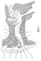
- Figure 1shows one configuration of a complete TRI device 1 in the human ear from a side perspective.
- Figure 1shows a canal open-ear model 1 made in an acrylic shell.
- the tympanic membrane, TM, or ear drum 3is deflected by sound waves emitting from the receiver 6 of the TRI 1.
- Two sources of soundreach the TM 3.
- One, soundis delivered by the TRI.
- the other soundsarrive from surrounding ambient sources, such as another human voice.
- the construction of the TRI 1is such that the external ear canal 2 is completely open in the inferior portion or bottom half 4. This is important to assure delivery of normal outside sounds, without introducing intermodulation that would alter the original signal.
- the retention arms 14 and 15position the shell housing of the TRI 1 to maintain the openness of the external ear canal 2 and properly aim the receiver at the superior portion of the TM 3, its most sensitive surface area.
- the electronic circuitis mounted on the faceplate 9 (see Fig.
- the canal-open-ear (COE) designis cosmetically a superior design as compared to a behind-the-ear (BTE) with the earmold and tubing connection which fits over the external ear (pina) 21. This is genuinely beneficial, since the perception of tinnitus sound can be habituated only when the stigma of wearing the device does not evoke any form of an emotional response associated with wearing the device.
- Microtronic #6 volume control adapter ring and wire 13could be insulated stranded wire similar to Litz 44 gauge 5 strand magnet wire.
- the present inventionthere is enhanced telephone use with the product in place, in terms of sound transmission and the placement of a phone receiver adjacent the external ear canal, as in usual use.
- the BTE productmust be repositioned with the telephone receiver if the BTE is also a hearing aid or removed if the BTE is not equipped with a microphone.
- the present inventionhas a matched acoustic response for both ears since the earmold and earmold tubing associated with BTE's are eliminated.
- the current designyields a better angle of attack for the sound spectrum to impinge the TM 3 as compared to the BTE whose receiver is housed behind the ear and must travel through earmold tubing and the earmold. Variances in the tubing length and earmold insertion depth affect the spectrum greatly.
- the present inventionhas a sound envelope of stable temporal characteristics, where head movement will not cause a change in the signal at the TM 3.
- Figure 2shows an open ear, helix based TRI 17. It is used to fit ears which are too small for the COE or CIC units by filling the concha bowl in the helix of the pina 21.
- the theory of operationis as above. A larger battery can also be used, increasing service life between battery changes.
- FIG 3shows an open ear, completely-in-the-canal (CIC) based TRI 18.
- the CIC TRI 18uses a unique positioning system to properly aim the receiver 6 at the TM 3. As in Figure 1 , this positioning is important to deliver a sound envelope of stable temporal characteristics, where head movement will not cause a change in the signal at the TM 3.
- the sagital plane or face plate 9is designed to have an opening at the apex of the external ear canal 2, then to leave the inferior portion 4 of the ear canal free and unobstructed medially until the distal, or medial end of the device where a medial ipsolateral-route-of-signal (IROS) vent retainer 33 supports the device 18 upward into the superior portion of the external ear canal 2 and at the same time keeping the inferior canal 4 open and veritably unobstructed for free-field sound transmission.
- IROSmedial ipsolateral-route-of-signal
- the CICis the product of choice to offer the best cosmetic solution and has a built in extraction cord 22 since the device resides deeply in the external ear canal 2.
- This extraction cord 22also serves as a volume control extension which allows adjustment of the noise level by rolling the nubbin on the cord between the index finger and thumb.
- the CIC designpreferably uses a battery size "5 A” and should use an efficient circuit, such as the class D ( Fig. 8 ), to have a reasonable battery life.
- Figure 4shows an alternative retention design for an open ear CIC 118; all theory of operation remains the same.
- Figure 5shows a COE based TRI device graphically illustrated via magnetic resonance imaging (MRI) in a typical human ear as viewed from the top of the head, superior to inferior.
- MRImagnetic resonance imaging
- the external ear canal 2 and its first and second directional bendare exhibited.
- the anterior 24 and posterior 25 planesare shown to demonstrate how the COE shell must be molded to faithfully follow the ear canal.
- the helix 14 and cavum 15 retention armsmaintain the spatial relationships to fill the superior canal while the inferior canal 4 is left open, at the same time the anterior 24 and posterior 25 canal quadrants are filled, aiming the receiver at the superior portion of the TM 3.
- FIG. 6shows a preferred embodiment of a Class A electrical circuit.
- a basic operational amplifier 27feeds into a transistor 28 forming the basic circuit.
- a Zener diode 29, Motorola type MLL4684 or equivalent,is set between ground potential and input into a capacitor 30 which establishes the corner frequency of the amplifier circuit.
- the noise generator formed by the Zener diode 29 and the RC input circuitrequires very little current drain which is primarily dictated by the requirements of the OpAmp/Transistor.
- the transducersare selected based on frequency response and impedance. Higher impedance transducers reduce the current draw. The total current drain required for the device is governed by the electrical / acoustic efficiency of the transducer and how much sound volume the device is set to deliver.
- the volume control 12 taperis selected to have as much "bend" in it as possible. The reason is that most of the control occurs in the first few thousands of Ohms of resistance. So if the resistance selected on the volume control is minimum, gain is maximized to the loudest noise output. Resistance taper of the volume control yields about one and a half dB increments with a range typically of twenty-four dB.
- the transduceris a model ED 1914 commercially available from Knowles Electronics, Chicago, IL, and V B is a battery which can last typically about 60 hours.
- FIG. 7shows a preferred embodiment of a two-stage Class A electrical circuit which has balanced stages for smoother voltage gain resulting in improved stability of signal and better battery life.
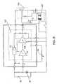
- FIG. 8shows a preferred embodiment of a three-stage Class D electrical circuit device combined with any of the shell models described herein or manufactured with an application-specific integrated circuit, where the amplifier input stage and the C-MOS output stage (class D) are populated on the same hybrid or on two separate hybrids.
- a basic operational amplifier 27feeds into an inverting operational amplifier 128 forming the basic circuit.
- a Zener diode 29, Motorola type MLL4684 or equivalent,is set between ground potential and input into a capacitor 30 which establishes the corner frequency of the amplifier circuit.
- the noise generator formed by the Zener diode 29 and the RC input circuitrequires very little current drain which is primarily dictated by the requirements of the Op Amp/Inverting Op Amp.
- the transducersare selected based on frequency response and impedance. Higher impedance transducers reduce the current draw.
- the total current drain required for the deviceis governed by the electrical / acoustic efficiency of the transducer and how much sound volume the device is set to deliver.
- the volume control 12 taper, as in the Class A design,is selected to have as much "bend" in it as possible. The reason is that most of the control occurs in the first few thousands of Ohms of resistance.
- the gain of the circuitis determined by a sum of the series gains of the subcircuits measured in decibels. So if the resistance selected on the volume control is minimum, gain is maximized to the loudest noise output.
- the receiver 306could be a model FD 3286 or model FD 3287, commercially available from Cherry Electronics, Chicago, IL.
- Trimmer 130is a 100K variable resistor.
- FIG. 9shows a preferred embodiment of a programmable K-amp three-stage Class D electrical circuit.
- a suitable circuit for this purposeis shown in U.S. Patent No. 5,131,046 .
- FIG. 10shows a preferred embodiment of a programmable IntrigueTM three-stage, two-channel Class D electrical circuit.
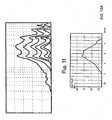
- Figure 11shows the frequency response of various volume control positions of the TRI 1, as measured on a Madsen Electronics, Inc. Model "Auricle” using a NOAH interface with a direct access 2 cc coupler.
- Table 1.shows the relationship of volume control rotation to noise gain.
- the taper of the volume control (VC)is set to give very discrete adjustment in the very low gain, barely audible ranges, with excellent voltage stability and a sound envelope of stable temporal characteristics, where head movement will not cause a change in the signal as measured at the TM 3.
- the VCwas further designed to have a very quiet operation, free of scratchiness and changes in the consistency of taper during increase or decrease of gain.
- Figures 12A-12Eshow the spectrum characteristics of the intact noise stimulator which generates between an 82 dB and 85 dB noise level. The data is the average for nine devices.
Landscapes
- Engineering & Computer Science (AREA)
- Health & Medical Sciences (AREA)
- Physics & Mathematics (AREA)
- Acoustics & Sound (AREA)
- Signal Processing (AREA)
- General Health & Medical Sciences (AREA)
- Otolaryngology (AREA)
- Neurosurgery (AREA)
- Life Sciences & Earth Sciences (AREA)
- Biomedical Technology (AREA)
- Manufacturing & Machinery (AREA)
- Physiology (AREA)
- Biophysics (AREA)
- Psychology (AREA)
- Heart & Thoracic Surgery (AREA)
- Vascular Medicine (AREA)
- Animal Behavior & Ethology (AREA)
- Public Health (AREA)
- Veterinary Medicine (AREA)
- Neurology (AREA)
- Prostheses (AREA)
- Measurement And Recording Of Electrical Phenomena And Electrical Characteristics Of The Living Body (AREA)
Description
- The present invention relates to an Auditory Pathway Stimulator for management through central habituation of patients suffering from Tinnitus or Hyperacusis, or both. More particularly, the present invention relates to a system and method for reducing the debilitating effects of tinnitus by means of an all-in-the-canal, open-ear, noise stimulus of the auditory pathway.
- Tinnitus is a wide spread auditory symptom affecting approximately 17% of the general population growing to 33 % in the elderly. This percentage translates to about 44 million people in the United States. Most who experience tinnitus manage well, in that it is not disruptive in daily life. However, approximately 25% of people experiencing tinnitus are encumbered to the extent that they actively seek help. The above statistics correspond to approximately 10 million sufferers in the United States and 2 million of these sufferers are debilitated by tinnitus to the point of total disruption of the quality of life (Jastreboff P.J., Gray W.C., and Gold S.L.: "Neurophysiological Approach to Tinnitus Patients", The American Journal of Otology, 17:236-340 ©1996). In fact, some extreme cases have led to suicide. At present, there is no cure for tinnitus. Most sufferers are told by medical and audiological professionals they should "learn to live with it."
- Over 300 research projects funded by public and private agencies have been conducted to address tinnitus and its harmful effects during the last two decades. A cure is still unforeseen in the near future. This invention is an important step to a systematic solution with long-term significant results.
- The concept of tinnitus is difficult to convey since it is a "Phantom Auditory Perception" representing lack of certain neuro activity in the auditory system rather than an increased activity. It is also a symptom associated with many auditory and non auditory pathologies.
- Unmanageable tinnitus is due to a conditioned reflex between the central auditory pathways and the limbic system. In short, when the auditory brainstem detects a new sound such as tinnitus it automatically assigns high priority to the new auditory signal. This detection in turn provokes a negative emotional association in the limbic system producing a very strong conditioned reflex perceived as a thread which activates the body's fight-or-flight response and since this is an internally generated sound one can not control its volume or remove themselves from it.
- In the case of tinnitus, once the new pattern of auditory neural activity is detected and locked into the limbic system the tinnitus becomes extremely prominent. Basic neuroscience predicts that it is relatively easy to reverse this signal recognition process by exposing the patient to low levels of broad band noise for a long period of time. This broad band noise will interfere with the tinnitus recognition process making it more difficult to separate the tinnitus signal from background neuronal activities and, since there are no longer other processes increasing recognition of this intruding signal the tinnitus becomes no longer detected.
- In recent years masking of tinnitus using various noise signals of adjustable width and amplitude have been developed as a result of scientific research done by Jack Vernon. These devices yielded very limited success. More recently, a neurophysiological model of tinnitus management has been developed by Pawel Jastreboff. Using specific protocol, attempts were made to habituate patients to the presence of tinnitus. Habituation infers training patients not to be aware of tinnitus except when deliberately focusing their attention on it. Even then, perceived tinnitus should no longer induce annoyance or irritation.
- It has been shown that the introduction of a noise signal can help in the therapy. Behind-the-ear noise generators have yielded an 83 percent success rate. Yet the units remain big, cumbersome and cosmetically unappealing.
- Manufacturers of hearing aids are regulated by the United States Food and Drug Administration (FDA) as a medical device establishment. Hearing aid components used in the assembly of custom open-ear tinnitus habituators and produced as a combined hearing aid/tinnitus habituator device or as a stand-alone tinnitus device will be categorized, not as a Class I hearing device, but rather as a Class III prosthetic device under 21 C.F.R. § 874.3400 entitled "Tinnitus masker". The tinnitus habituator differs from the tinnitus masker in that it does not emit a signal intended to overpower the tinnitus head/ear noise, but to stimulate the auditory pathways with a broad-band low-level signal. Its intent, however, is to aid in tinnitus and FDA has decided the device described in this application will fall into the Class III classification. FDA regulates medical devices based on safety and effectiveness. The hearing aid components used in the construction of the tinnitus habituator have been used in the assembly of millions of Class I hearing aids and are therefore known to be safe when used as directed. The efficacy is the issue, in that there is no established protocol by FDA in the management of tinnitus. The Class III classification stems from the absence of this protocol. The Class I level would be more cost-efficient to produce and in turn reduce the cost to the public. It is the protocol that teaches the patient to focus on the signal of the tinnitus habituator and not focus on the tinnitus head noise which enables the tinnitus device though central auditory habituation to reduce the debilitating effects of tinnitus or hyperacusis. Tinnitus habituators without a well designed therapy would not be significantly effective. Also, masking tinnitus via a traditional masker is counter productive (Gold S.L., Gray W.C., Hu S., and Jastreboff P.W. "Selection and Fitting of Noise Generators and Hearing Aids for Tinnitus Patients", Proceedings of the Fifth International Tinnitus Seminar 1995 edited by Reich G.E. and Vernon J.A. ©American Tinnitus Association, Portland OR USA 1996 p.312-314;Jastreboff P.J. and Hazel J.W.P. "A Neurophysiological Approach to Tinnitus: Clinical Implications" British Journal of Audiology, 1993. 27. 7-17). It is very important to avoid masking tinnitus. In fact, there are reports of patients having long term "masking" therapy who realized no relief from the perception of the tinnitus or the annoyance resulting from the tinnitus. After entering into habituation therapy, both the perception of and the annoyance from tinnitus were reduced (Jastreboff P.J., Gray W.C., and Gold S.L.: "Neurophysiological Approach to Tinnitus Patients", The American Journal of Otology, 17:236-340 ©1996).
- Products designed to be used to fill the room with a low level noise, not FDA regulated, have proven to offer minimum effectiveness, because sound reaching the ear drum is unstable and inconsistent due to head shadow effect, occlusion to the external ear canal, and the Doppler effect caused by motion of the patient's head, such as turning back and forth vigorously. Additionally, the size of this unit makes it difficult to transport and impractical to use outside of the home since the noise would distract others.
U.S. Patent No. 5,403,262 issued to Gooch describes a circuit means of random noise generation, which is digitally processed to selected center frequencies, bandwidth and intensity. A random noise signal is transduced to acoustical energy by a speaker or headphone. Other means of delivering the masking signal to the patient's ear may be by way of using a low-power transmitter or electromagnetic coil to deliver the signal from the tinnitus masker to a receiver worn in or on the sufferer's ear. Gooch's circuit is intended for room noise generation to mask tinnitus, not habituate it, as a patient goes to sleep.U.S. Patent No. 5,325,872, issued to Westerham et al. , discloses an invention which relates to a Tinnitus masker with one or more signal generators, a controllable amplifier, transducers and comprises means for generating a continuously repeated, sinusoidal pure-tone signal which continuously and slowly moves through an audiofrequency range in a cyclic manner to remove tinnitus for a period of time. Westerham et al. predicates its design of the masker on the reasoning that "tinnitus is very frequently perceived as a tone". The described embodiment is a behind-the-ear (B-T-E) device.U.S. Patent No. 4,222,393 issued to Hocks et al. describes a Tinnitus masker device whereby the patient is subjected to external sounds of different pitch, one right after another, to enable the patient to identify the particular external sound having the same pitch as the subjective tinnitus sound perceived by the patient. The patient is then provided a power-operated sound generator producing a range of frequencies extending above and below the perceived pitch to mask the tinnitus sound. The tinnitus masker may be worn in the same manner as a hearing aid or combined with one. Once again, the device is a masker intended to immerse the tinnitus head noise below audibility. This is accomplished by using a noise signal with a patient-selected center frequency where the output noise signal is of broader band-width and intensity than the tinnitus therefore facilitating a masking effect of the tinnitus. The actual noise generation of the masker is by a noise generator. It can only be produced in a behind-the-ear instrument.U.S. Patent No.5,167,236 issued to Junker describes a behind-the-ear Tinnitus-masker which is an electronic circuit designed so that the sound spectrum produced through an ear-piece contains a line spectrum with a fundamental tone.U.S. Patent No. 4,870,688 issued to Voroba et al. describes a hearing aid comprising an electronic circuit designed using a pseudorandom frequency noise generator as a sound source to be connected to a hearing aid circuit for use in patients with "ringing" or "buzzing" in the head, commonly called tinnitus. The drawings in the patent do not define the object and only identify a standard hearing aid microphone as the source.- Other patents that may be of interest include the following:
U.S. Patent No. 5,024,612 , External ear canal pressure regulating device and tinnitus suppression device;U.S. Pat No. 5,628,330 , Apparatus for treating people afflicted with tinnitus;U.S. Patent No. 4,735,968 , Method of treating tinnitus with AOAA;U.S. Patent No. 5,279,292 , Charging system for implantable hearing aids and tinnitus maskers;U.S. Patent No. 5,064,858 , Protected complex of procaine for the treatment of symptoms from narcotics addiction, tinnitus and Alzheimer's disease;U.S. Patent No. 4,954,486 , Furosemide as tinnitus suppressant;U.S. Patent No. 4,984,579 , Apparatus for treatment of sensorineural hearing loss, vertigo, tinnitus and aural fullness;U.S. Patent No. 4,956,391 , Protected complex of procaine for the treatment of symptoms from narcotics addiction, tinnitus and Alzheimer's disease;U.S. Patent No. 5,589,183 , Method and apparatus for treatment of neurogenic diabetes mellitus, and other conditions;U.S. Patent No. 4,759,070 , Patient controlled master hearing aid;U.S. Patent No. 4,226,248 , Phonocephalographic device;U.S. Patent No. 5,563,140 , Use of 1-(aminoalkyl)-3-(benzyl)-quinoxaline-2-one derivatives for the preparation of neuroprotective compositions;U.S. Patent No. 4,680,798 , Audio signal processing circuit for use in a hearing aid and method for operating same;U.S. Patent No. 3,764,748 , Implanted hearing aids;- Whether the failure of current tinnitus devices is due to the incomplete or inaccurate clinical knowledge or whether the failure is existing product performance, the end result is tinnitus and hyperacusis patients are experiencing an inadequate quality of life.
- The apparatus of the present invention solves the problems confronted in the art in a simple and straightforward manner.
- Unlike Gooch, the present invention is completely self-contained in the ear shell and does not use electromagnetic or transmitter technology. Further, it does not incorporate digital technology for band-width and center-frequency selection. The present invention performs optimally in open-ear design. In many cases the stimulator can be combined with a hearing aid circuit to compensate for a hearing loss.
- Unlike Hocks et al., the present invention embodies an open-ear in-the-canal device without insertion loss and with better cosmetics. Further, noise generation is by thermal circuit noise, requiring fewer electronic components and better product reliability.
- Unlike Voroba et al., the sound source may be a thermal noise specifically designed for band width, gain and low current drain optimized for hearing aid batteries. It is not a pseudorandom frequency noise generator.
- The sound generator of an embodiment of the present invention provides sound of stable temporal characteristics, such that head movement does not cause a change in the signal at the TM of the wearer of the present invention.
- The sound generator of an embodiment of the present invention provides a wide band sound spectrum to emulate real world sound so there is not a strong negative association with a new pattern sound in the central auditory system.
- The present invention is a cosmetically superior design as compared to a BTE with the earmold and connecting tube assembly. This feature is genuinely beneficial since the perception of tinnitus sound or any sound can be habituated only when the stigma of wearing the device does not evoke any form of negative emotional response.
- The present invention allows enhanced telephone use with the product of the present invention in place.
- The current invention does not have moisture problems as those associated with BTE's in the earmold tubing; the current invention eliminates the need for earmold tubing.
- The current design has a matched acoustic response for both ears since the earmold and earmold tubing are eliminated.
- The current design yields a better angle of attack for the sound spectrum to impinge the TM as compared to the BTE whose receiver is housed behind the ear and must travel through earmold tubing and the earmold. Variances in the tubing length and earmold insertion depth of BTE's affect the spectrum greatly.
- The current design is less susceptible to wax impaction since the receiver is located in the superior external ear canal quadrant.
- The device according to an embodiment of the present invention has a volume control taper which allows very discrete adjustment of low level sounds while maintaining a very stable signal output.
- For a further understanding of the nature, objects, and advantages of the present invention, reference should be had to the following detailed description, read in conjunction with the following drawings, wherein like reference numerals denote like elements and wherein:
FIG. 1 shows a canal open-ear device in a human ear;FIG. 2 shows a Helix open-ear device in a human ear;FIG. 3 shows a CIC open-ear device in a human ear;FIG. 4 shows the CIC open-ear device with an alternative retention system to hold the device in place in the human ear;FIG. 5 shows the device graphically illustrated via magnetic resonance imaging (MRI) in a typical human ear as viewed from the top of the head, superior to inferior.FIG. 6 shows a preferred embodiment of a Class A electrical circuit, in which the volume control is accomplished with a 100K ohm variable resistor in which minimum resistance yields maximum volume;FIG. 7 shows a preferred embodiment of a two-stage Class A electrical circuit;FIG. 8 shows a preferred embodiment of a three-stage Class D electrical circuit;FIG. 9 shows a preferred embodiment of a programmable K-amp three-stage Class D electrical circuit;FIG. 10 shows a preferred embodiment of a programmable Intrigue™ three-stage Class D electrical circuit;FIG. 11 shows the frequency response of various volume control positions of the TRI; andFIGS. 12A-12E show frequency spectrums of the noise signal with a 1.5V battery, wherein "SPL" is root-mean-square noise sound pressure level generated by the device of the present invention, withFig. 12A showing a maximum level of 82.1 dB SPL, withFig. 12B showing a maximum level of 82.7 dB SPL, withFig. 12C showing a maximum level of 82.9 dB SPL, withFig. 12D showing a maximum level of 85.5 dB SPL, withFig. 12E showing a maximum level of 86.4 dB SPL.- During development, as the open ear auditory pathway stimulator, to manage tinnitus and hyperacusis, was nearing completion, it was referred to as a Tinnitus Retraining Instrument (TRI). This describes the associated therapy more than the device but segregates it from other devices, such as maskers.
Figure 1 shows one configuration of acomplete TRI device 1 in the human ear from a side perspective.Figure 1 shows a canal open-ear model 1 made in an acrylic shell. The tympanic membrane, TM, orear drum 3 is deflected by sound waves emitting from thereceiver 6 of theTRI 1. Two sources of sound reach theTM 3. One, sound is delivered by the TRI. The other sounds arrive from surrounding ambient sources, such as another human voice. The construction of theTRI 1 is such that theexternal ear canal 2 is completely open in the inferior portion orbottom half 4. This is important to assure delivery of normal outside sounds, without introducing intermodulation that would alter the original signal. If the external ear canal is occluded, typically low frequencies are introduced, making the wearer report that their voice sounds like it is in a barrel. If theexternal ear canal 2 is sufficiently open (approximately 50 percent), the ear canal resonance is unchanged and the wearer reports normal sound quality. The same performance would be accomplished if the superior ear canal were left open, although wax-related problems with thereceiver 6 make it a less-than-optimum design in terms of product reliability. Theretention arms TRI 1 to maintain the openness of theexternal ear canal 2 and properly aim the receiver at the superior portion of theTM 3, its most sensitive surface area. The electronic circuit is mounted on the faceplate 9 (seeFig. 3 ) with abattery door 10 andbattery contacts 11 connecting power vialitz wire 13 to thenoise source 8 then to theamplifier 7 and on to thereceiver 6, where noise is generated and directed through anacoustic horn 23 to theTM 3. The level of transmitted noise is adjusted by thevolume control 12. The canal-open-ear (COE) design is cosmetically a superior design as compared to a behind-the-ear (BTE) with the earmold and tubing connection which fits over the external ear (pina) 21. This is genuinely beneficial, since the perception of tinnitus sound can be habituated only when the stigma of wearing the device does not evoke any form of an emotional response associated with wearing the device.- One could use a
Microtronic # 6 volume control adapter ring andwire 13 could be insulated stranded wire similar to Litz 44gauge 5 strand magnet wire. - With the present invention, there is enhanced telephone use with the product in place, in terms of sound transmission and the placement of a phone receiver adjacent the external ear canal, as in usual use. The BTE product must be repositioned with the telephone receiver if the BTE is also a hearing aid or removed if the BTE is not equipped with a microphone. Additionally, the present invention has a matched acoustic response for both ears since the earmold and earmold tubing associated with BTE's are eliminated. The current design yields a better angle of attack for the sound spectrum to impinge the
TM 3 as compared to the BTE whose receiver is housed behind the ear and must travel through earmold tubing and the earmold. Variances in the tubing length and earmold insertion depth affect the spectrum greatly. The present invention has a sound envelope of stable temporal characteristics, where head movement will not cause a change in the signal at theTM 3. Figure 2 shows an open ear, helix basedTRI 17. It is used to fit ears which are too small for the COE or CIC units by filling the concha bowl in the helix of thepina 21. The theory of operation is as above. A larger battery can also be used, increasing service life between battery changes.Figure 3 shows an open ear, completely-in-the-canal (CIC) basedTRI 18. TheCIC TRI 18 uses a unique positioning system to properly aim thereceiver 6 at theTM 3. As inFigure 1 , this positioning is important to deliver a sound envelope of stable temporal characteristics, where head movement will not cause a change in the signal at theTM 3. The sagital plane orface plate 9 is designed to have an opening at the apex of theexternal ear canal 2, then to leave theinferior portion 4 of the ear canal free and unobstructed medially until the distal, or medial end of the device where a medial ipsolateral-route-of-signal (IROS) ventretainer 33 supports thedevice 18 upward into the superior portion of theexternal ear canal 2 and at the same time keeping theinferior canal 4 open and veritably unobstructed for free-field sound transmission. The CIC is the product of choice to offer the best cosmetic solution and has a built inextraction cord 22 since the device resides deeply in theexternal ear canal 2. Thisextraction cord 22 also serves as a volume control extension which allows adjustment of the noise level by rolling the nubbin on the cord between the index finger and thumb. The CIC design preferably uses a battery size "5 A" and should use an efficient circuit, such as the class D (Fig. 8 ), to have a reasonable battery life.Figure 4 shows an alternative retention design for anopen ear CIC 118; all theory of operation remains the same.Figure 5 shows a COE based TRI device graphically illustrated via magnetic resonance imaging (MRI) in a typical human ear as viewed from the top of the head, superior to inferior. Theexternal ear canal 2 and its first and second directional bend are exhibited. The anterior 24 and posterior 25 planes are shown to demonstrate how the COE shell must be molded to faithfully follow the ear canal. Thehelix 14 andcavum 15 retention arms maintain the spatial relationships to fill the superior canal while theinferior canal 4 is left open, at the same time the anterior 24 and posterior 25 canal quadrants are filled, aiming the receiver at the superior portion of theTM 3.FIG. 6 shows a preferred embodiment of a Class A electrical circuit. A basicoperational amplifier 27 feeds into atransistor 28 forming the basic circuit. AZener diode 29, Motorola type MLL4684 or equivalent, is set between ground potential and input into acapacitor 30 which establishes the corner frequency of the amplifier circuit. The noise generator formed by theZener diode 29 and the RC input circuit requires very little current drain which is primarily dictated by the requirements of the OpAmp/Transistor. The transducers are selected based on frequency response and impedance. Higher impedance transducers reduce the current draw. The total current drain required for the device is governed by the electrical / acoustic efficiency of the transducer and how much sound volume the device is set to deliver. Thevolume control 12 taper is selected to have as much "bend" in it as possible. The reason is that most of the control occurs in the first few thousands of Ohms of resistance. So if the resistance selected on the volume control is minimum, gain is maximized to the loudest noise output. Resistance taper of the volume control yields about one and a half dB increments with a range typically of twenty-four dB. InFigure 6 , the transducer is a model ED 1914 commercially available from Knowles Electronics, Chicago, IL, and VB is a battery which can last typically about 60 hours.FIG. 7 shows a preferred embodiment of a two-stage Class A electrical circuit which has balanced stages for smoother voltage gain resulting in improved stability of signal and better battery life.FIG. 8 shows a preferred embodiment of a three-stage Class D electrical circuit device combined with any of the shell models described herein or manufactured with an application-specific integrated circuit, where the amplifier input stage and the C-MOS output stage (class D) are populated on the same hybrid or on two separate hybrids. A basicoperational amplifier 27 feeds into an invertingoperational amplifier 128 forming the basic circuit. AZener diode 29, Motorola type MLL4684 or equivalent, is set between ground potential and input into acapacitor 30 which establishes the corner frequency of the amplifier circuit. The noise generator formed by theZener diode 29 and the RC input circuit requires very little current drain which is primarily dictated by the requirements of the Op Amp/Inverting Op Amp. The transducers are selected based on frequency response and impedance. Higher impedance transducers reduce the current draw. The total current drain required for the device is governed by the electrical / acoustic efficiency of the transducer and how much sound volume the device is set to deliver. Thevolume control 12 taper, as in the Class A design, is selected to have as much "bend" in it as possible. The reason is that most of the control occurs in the first few thousands of Ohms of resistance. The gain of the circuit is determined by a sum of the series gains of the subcircuits measured in decibels. So if the resistance selected on the volume control is minimum, gain is maximized to the loudest noise output. Resistance taper of the volume control yields about one and a half dB increments with a range typically of thirty-eight dB. InFigure 8 , thereceiver 306 could be a model FD 3286 or model FD 3287, commercially available from Cherry Electronics, Chicago, IL.Trimmer 130 is a 100K variable resistor.FIG. 9 shows a preferred embodiment of a programmable K-amp three-stage Class D electrical circuit. A suitable circuit for this purpose is shown inU.S. Patent No. 5,131,046 .FIG. 10 shows a preferred embodiment of a programmable Intrigue™ three-stage, two-channel Class D electrical circuit.Figure 11 shows the frequency response of various volume control positions of theTRI 1, as measured on a Madsen Electronics, Inc. Model "Auricle" using a NOAH interface with adirect access 2 cc coupler. Table 1. shows the relationship of volume control rotation to noise gain. The taper of the volume control (VC) is set to give very discrete adjustment in the very low gain, barely audible ranges, with excellent voltage stability and a sound envelope of stable temporal characteristics, where head movement will not cause a change in the signal as measured at theTM 3. The VC was further designed to have a very quiet operation, free of scratchiness and changes in the consistency of taper during increase or decrease of gain.Figures 12A-12E show the spectrum characteristics of the intact noise stimulator which generates between an 82 dB and 85 dB noise level. The data is the average for nine devices.- The following is a list of elements used in the drawings and potential commercially available products which could be used as these elements:
- 1 COE shell
- 2 external ear canal
- 3 TM
- 4 inferior quadrant of the external ear canal
- 6 receiver
- 7 amplifier circuit
- 8 noise source circuit
- 9 face plate (such as an Entech 10A face plate)
- 10 battery door (such as an Entech 10A battery door)
- 11 battery compartment (e.g., an Entech 10A insulated battery compartment boot)
- 12 volume control (Microtronic, e.g.)
- 13 litz wires
- 14 concha retention arm
- 15 cavum retention arm
- 17 Helix Based OE-TRI device
- 18 CIC based TRI device
- 21 pina
- 22 extraction cord
- 23 acoustic horn
- 24 anterior ear canal
- 25 posterior ear canal
- 27 operational amplifier
- 28 transistor
- 29 Zener diode (such as a NTE Electronics Cat # 5005A Zener Diode)
- 30 capacitor (such as a Tansitor® .068 microfarad capacitor)
- 33 vent retainer
- 34 vertical wall occupying coronal plane from superior to inferior to keep
device 118 in place despite jaw action - 35 footer to spread pressure of downward force of
device 118 onto the inferior external canal across a sufficient surface area so as not to cause undue pressure on the superficial nerve endings of the external ear canal - 106 Knowles® ED 1914 receiver
- 108 Microphone (Knowles)
- 117 Microtronic variable resistor
- 118 alternative CIC based TRI device
- 119 output capacitor (Tansitor®)
- 120 1.1 V DC battery cell (typically #13, 312, 10A, and 5A from Rayovac)
- 124 Microtronic PJ 88 Volume Control
- 125 high frequency boost capacitor (Tansitor®)
- 131 on-board regulator
- 201 bias resistor (such as a
Brill International 47 Ohm resistor) - 202 feedback resistor for noise generator (such as a Brill International 10 k ohm resistor)
- 203 resistor (such as a
Brill International 100 Ohm resistor) - 206 Receiver (Knowles)
- 218 output capacitor
- 219 output isolation capacitor (Tansitor®) (duplication of Vbatt)
- 227 Monolithic IC High Gain Class A Amplifier
- 327 Monolithic IC (Two stage) High Gain Class A Amplifier
- 395 Tansitor® 2.2 microfarad capacitor
- 397 Tansitor® .047 microfarad capacitor
- 427 Monolithic IC (Two stage) High Gain Class D Amplifier
- 527 C-MOS amplifier, output stage Class D
- 627 K-amp programmable integrated circuit, commercially available from Etymotic Research
- CIN 220 nano farad capacitor
- All measurements disclosed herein are at standard temperature and pressure, at sea level on Earth, unless indicated otherwise. All materials used or intended to be used in a human being are biocompatible, unless indicated otherwise.
- The foregoing embodiments are presented by way of example only; the scope of the present invention is to be limited only by the following claims.
| Table 1. Volume control position to output noise level | ||
| VC Set | Gain | Peak Frequency |
| On | -5 dB | 10,000 Hz |
| 1/8 On | -4 dB | 2727 Hz |
| 2/8 On | 0 dB | 2720 Hz |
| 3/8 On | 10 dB | 2720 Hz |
| ½ On | 13 dB | 2720 Hz |
| 5/8 On | 16 dB | 2800 Hz |
| ¾ On | 17 dB | 2800 Hz |
| 7/8 On | 19 dB | 2720 Hz |
| 7.5/8 On | 25 dB | 2720 Hz |
| Full-on | 38 dB | 2900 Hz |
Claims (18)
- An in-the-ear device for treating tinnitus, said device comprising :- a housing (1) which is configured to fit within an ear canal (2) of a user, said ear canal (2) including a tympanic membrane (3),- a sound generator within said housing (1) for generating sounds to habituate said tinnitus, and- a receiver (6) within said ear canal (2) for delivering said sounds from said sound generator to said user so that said tympanic membrane (3) is deflected by said sounds,characterized in that said housing can be positioned within the car canal (2) so that the ear canal (2) is at least partially open to receive sounds from surrounding ambient sources,
said device further comprising retention arms or a vent retainer, for positioning said housing (1) within said ear canal (2) so that said ear canal (2) is at least partially open to receive sounds from surrounding ambient sources. - The in-the-ear device according to claim 1, wherein said sound generator is configured to provide a wide band sound spectrum to emulate real world sound.
- The in-the-ear device according to claim 1, wherein said sound generator is configured to generate sound of stable temporal characteristics so that user head movement does not cause any change in signal at the user's tympanic membrane (3).
- The in-the-ear device according to claim 1, wherein said sound generator comprises a noise generator and said positioning means is configured to aim said receiver at the superior portion of the user's tympanic membrane.
- The in-the-ear device according to claim 4, wherein said sound generator comprises a noise source (8), an amplifier (7) connected to said noise source (8), and said receiver (6) connected to said amplifier (7), and a horn (13) within said housing connected to said receiver (6).
- The in-the-ear device according to claim 5, wherein said noise generating means further comprises means for adjusting noise level.
- The in-the-ear device according to claim 6, further comprising an extraction cord attached to said housing and said extraction cord is configured to serve as an extension for said noise level adjusting means.
- The in-the-ear device according to claim 1, further comprising a battery located within said housing.
- The in-the ear device according to claim 1, comprising upper and lower retention arms (14, 15) connected to said housing (1).
- The in-the-ear device according to claim 8, comprising a medial ipsolateral-route-of-signal vent retainer (33) attached to a distal end of said device, and wherein said retainer is configured to support the device upward into the superior portion of the external ear canal (2) while keeping the interior canal open and substantially unobstructed for free-field sound transmission.
- The in-the-ear device according to claim 10, further comprising said housing having a face plate (9) and said face plate (9) having an opening at the apex of the external ear canal (2).
- The in-the-ear device according to claim 1, wherein said sound generator comprises a programmable electric circuit.
- The in-the-ear device according to claim 1, wherein said sound generator comprises a subminiature electronic noise-generator means for generating noise within an external auditory canal (2) of a user of the device and means for adjusting the volume of the noise to habituate the user to tinnitus head/ear noise.
- The in-the-ear device according to claim 1, wherein said sound generator is programmable.
- The in-the-ear device according to claim 1, further comprising a hearing aid for amplifying ambient sounds.
- The in-the-ear device according to claim 1, further comprising said device being an open ear helix based device.
- The in-the-ear device according to claim 1, wherein said device is further configured to treat hyperacusis.
- The in-the-ear device according to claim 1, wherein said housing has an outer dimension which leaves said ear canal (2) at least partially open to receive sounds from surrounding ambient sources when said housing is positioned within said ear canal.
Applications Claiming Priority (3)
| Application Number | Priority Date | Filing Date | Title |
|---|---|---|---|
| US5494297P | 1997-08-07 | 1997-08-07 | |
| US54942P | 1997-08-07 | ||
| PCT/US1998/016412WO1999007302A1 (en) | 1997-08-07 | 1998-08-06 | Apparatus and method for an auditory stimulator |
Publications (3)
| Publication Number | Publication Date |
|---|---|
| EP1009316A1 EP1009316A1 (en) | 2000-06-21 |
| EP1009316A4 EP1009316A4 (en) | 2008-11-19 |
| EP1009316B1true EP1009316B1 (en) | 2013-10-09 |
Family
ID=21994524
Family Applications (1)
| Application Number | Title | Priority Date | Filing Date |
|---|---|---|---|
| EP98938429.2AExpired - LifetimeEP1009316B1 (en) | 1997-08-07 | 1998-08-06 | Apparatus and method for an auditory stimulator |
Country Status (6)
| Country | Link |
|---|---|
| US (1) | US6048305A (en) |
| EP (1) | EP1009316B1 (en) |
| KR (1) | KR100462116B1 (en) |
| AU (1) | AU8695798A (en) |
| UY (1) | UY25128A1 (en) |
| WO (1) | WO1999007302A1 (en) |
Families Citing this family (60)
| Publication number | Priority date | Publication date | Assignee | Title |
|---|---|---|---|---|
| US7787647B2 (en) | 1997-01-13 | 2010-08-31 | Micro Ear Technology, Inc. | Portable system for programming hearing aids |
| US6449662B1 (en) | 1997-01-13 | 2002-09-10 | Micro Ear Technology, Inc. | System for programming hearing aids |
| US6366863B1 (en)* | 1998-01-09 | 2002-04-02 | Micro Ear Technology Inc. | Portable hearing-related analysis system |
| DE19859171C2 (en)* | 1998-12-21 | 2000-11-09 | Implex Hear Tech Ag | Implantable hearing aid with tinnitus masker or noiser |
| DK1133898T3 (en)* | 1999-01-25 | 2002-12-09 | Widex As | Hearing aid system and hearing aid for in-situ fitting |
| US7520851B2 (en) | 1999-03-17 | 2009-04-21 | Neurominics Pty Limited | Tinnitus rehabilitation device and method |
| AUPP927599A0 (en)* | 1999-03-17 | 1999-04-15 | Curtin University Of Technology | Tinnitus rehabilitation device and method |
| US6879698B2 (en)* | 1999-05-10 | 2005-04-12 | Peter V. Boesen | Cellular telephone, personal digital assistant with voice communication unit |
| US6094492A (en)* | 1999-05-10 | 2000-07-25 | Boesen; Peter V. | Bone conduction voice transmission apparatus and system |
| US7508411B2 (en)* | 1999-10-11 | 2009-03-24 | S.P. Technologies Llp | Personal communications device |
| US6904402B1 (en)* | 1999-11-05 | 2005-06-07 | Microsoft Corporation | System and iterative method for lexicon, segmentation and language model joint optimization |
| AU2001229591A1 (en) | 2000-01-20 | 2001-07-31 | Starkey Laboratories, Inc. | Hearing aid systems |
| IL137373A0 (en)* | 2000-07-19 | 2001-07-24 | Optimal Focus Ltd | A hearing aid |
| KR100409279B1 (en)* | 2000-12-30 | 2003-12-18 | 임재중 | Electric stimulating device for medical treatment of ringing in the ears |
| US7421086B2 (en) | 2002-09-10 | 2008-09-02 | Vivatone Hearing Systems, Llc | Hearing aid system |
| US20050078843A1 (en)* | 2003-02-05 | 2005-04-14 | Natan Bauman | Hearing aid system |
| US7751580B2 (en)* | 2002-09-10 | 2010-07-06 | Auditory Licensing Company, Llc | Open ear hearing aid system |
| EP1988743A3 (en)* | 2003-02-05 | 2013-01-02 | Auditory Licensing Company, LLC | Hearing aid system |
| US20070021804A1 (en)* | 2003-05-30 | 2007-01-25 | Maltan Albert A | Stimulation using a microstimulator to treat tinnitus |
| US20050192514A1 (en)* | 2004-03-01 | 2005-09-01 | Kearby Gerald W. | Audiological treatment system and methods of using the same |
| US20050251226A1 (en)* | 2004-05-07 | 2005-11-10 | D Angelo John P | Suppression of tinnitus |
| US20060093997A1 (en)* | 2004-06-12 | 2006-05-04 | Neurotone, Inc. | Aural rehabilitation system and a method of using the same |
| WO2005124722A2 (en)* | 2004-06-12 | 2005-12-29 | Spl Development, Inc. | Aural rehabilitation system and method |
| FR2871982A1 (en)* | 2004-06-18 | 2005-12-23 | Michel Emanuel | Intra-aural hearing aid manufacturing method for hearing impaired person, involves creating recess between flat side and end of aid where earphone is placed, to open shell, and associating recess with openings of flat side and end |
| DE102004050133B4 (en)* | 2004-10-14 | 2007-12-13 | Bernd Kubicke | Open earmold |
| KR100647310B1 (en)* | 2005-01-26 | 2006-11-23 | 삼성전자주식회사 | Signal output method with frequency characteristics according to human auditory characteristics and tinnitus treatment device using same |
| US20070127757A2 (en)* | 2005-07-18 | 2007-06-07 | Soundquest, Inc. | Behind-The-Ear-Auditory Device |
| WO2007011846A2 (en)* | 2005-07-18 | 2007-01-25 | Soundquest, Inc. | In-ear auditory device and methods of using same |
| EP1932390A4 (en)* | 2005-09-06 | 2013-10-16 | Natan Bauman | Tinnitus treatment device |
| DE102006025718A1 (en)* | 2006-06-01 | 2007-12-06 | GEERS Hörakustik AG & Co. KG | Ear insert, in particular hearing aid ear insert |
| CA2601662A1 (en) | 2006-09-18 | 2008-03-18 | Matthias Mullenborn | Wireless interface for programming hearing assistance devices |
| US7856111B2 (en) | 2006-10-04 | 2010-12-21 | Siemens Audiologische Technik Gmbh | Hearing aid with sound tube serving for retention in concha |
| US10257628B2 (en) | 2006-11-27 | 2019-04-09 | Anova Hearing Labs, Inc. | Open fit canal hearing device |
| JP5520055B2 (en)* | 2007-03-07 | 2014-06-11 | ジーエヌ リザウンド エー/エス | Improvement of sound quality to reduce tinnitus depending on the classification of voice environment |
| CN101641968B (en)* | 2007-03-07 | 2015-01-21 | Gn瑞声达A/S | Sound enrichment for tinnitus relief |
| US8218799B2 (en)* | 2007-08-22 | 2012-07-10 | Matthew Stephen Murphy | Non-occluding audio headset positioned in the ear canal |
| US20110040205A1 (en)* | 2007-11-09 | 2011-02-17 | The City University | Treatment for Alleviating Tinnitus and Hyperacusis with Auditory Stimulation by Compensating for Hearing Loss and Loss of Non-Linear Compressions |
| KR100924984B1 (en) | 2007-12-12 | 2009-11-06 | 이승영 | Therapy device using broadband low frequency electromagnetic field |
| WO2009155650A1 (en)* | 2008-06-25 | 2009-12-30 | Cochlear Limited | Enhanced performance implantable microphone system |
| US8379897B2 (en)* | 2008-09-17 | 2013-02-19 | Daniel R. Schumaier | Hearing assistance device having reduced mechanical feedback |
| US8369554B2 (en)* | 2008-10-03 | 2013-02-05 | Zounds Hearing, Inc. | Open tip for hearing aid |
| US10097936B2 (en) | 2009-07-22 | 2018-10-09 | Eargo, Inc. | Adjustable securing mechanism |
| US10334370B2 (en) | 2009-07-25 | 2019-06-25 | Eargo, Inc. | Apparatus, system and method for reducing acoustic feedback interference signals |
| US10284977B2 (en) | 2009-07-25 | 2019-05-07 | Eargo, Inc. | Adjustable securing mechanism |
| EP2498874B1 (en)* | 2009-11-10 | 2017-09-20 | MED-EL Elektromedizinische Geräte GmbH | Implant power system |
| WO2011088887A1 (en)* | 2010-01-19 | 2011-07-28 | Widex A/S | Hearing aid ear plug with an extraction cord |
| HUE055666T2 (en) | 2010-11-23 | 2021-12-28 | Nat Univ Ireland Maynooth | Method and apparatus for sensory substitution |
| WO2012149970A1 (en)* | 2011-05-04 | 2012-11-08 | Phonak Ag | Adjustable vent of an open fitted ear mould of a hearing aid |
| KR101279766B1 (en)* | 2012-04-06 | 2013-07-04 | 조선대학교산학협력단 | Medical apparatus and method for correcting adaptive hearing |
| US10165372B2 (en) | 2012-06-26 | 2018-12-25 | Gn Hearing A/S | Sound system for tinnitus relief |
| US12311114B2 (en) | 2013-08-30 | 2025-05-27 | Neuromod Devices Limited | Method and apparatus for treating a neurological disorder |
| EP2870949B1 (en)* | 2013-11-12 | 2016-05-25 | Julia Draxler-Schinko | Mechanical tinnitus noiser |
| US9532736B2 (en) | 2013-12-12 | 2017-01-03 | Charles Paul Rush | Portable electronic device with a tinnitus relief application |
| US10821027B2 (en) | 2017-02-08 | 2020-11-03 | Intermountain Intellectual Asset Management, Llc | Devices for filtering sound and related methods |
| AU2018243565B2 (en) | 2017-03-30 | 2023-03-16 | Magic Leap, Inc. | Non-blocking dual driver earphones |
| US10835931B2 (en) | 2017-10-17 | 2020-11-17 | Eargo, Inc. | Device-cleaning wax guards |
| US11140498B2 (en) | 2017-10-17 | 2021-10-05 | Eargo, Inc. | Wax management system |
| US10582286B2 (en)* | 2018-06-22 | 2020-03-03 | University Of South Florida | Method for treating debilitating hyperacusis |
| KR102244599B1 (en)* | 2019-06-07 | 2021-04-23 | 한림대학교 산학협력단 | Apparatus, method and program for monitoring of tinnitus treatment |
| WO2025166193A1 (en)* | 2024-02-02 | 2025-08-07 | Regents Of The University Of Minnesota | Systems and methods for bimodal neuromodulation for tinnitus treatment |
Citations (1)
| Publication number | Priority date | Publication date | Assignee | Title |
|---|---|---|---|---|
| WO1990003089A1 (en)* | 1988-09-15 | 1990-03-22 | Epic Corporation | Apparatus and method for conveying amplified sound to ear |
Family Cites Families (20)
| Publication number | Priority date | Publication date | Assignee | Title |
|---|---|---|---|---|
| US3764748A (en)* | 1972-05-19 | 1973-10-09 | J Branch | Implanted hearing aids |
| US4222393A (en)* | 1978-07-28 | 1980-09-16 | American Tinnitus Association | Tinnitus masker |
| US4226248A (en)* | 1978-10-26 | 1980-10-07 | Manoli Samir H | Phonocephalographic device |
| GB2134689A (en)* | 1983-01-26 | 1984-08-15 | Nat Res Dev | Tinnitus masking |
| US4680798A (en)* | 1984-07-23 | 1987-07-14 | Analogic Corporation | Audio signal processing circuit for use in a hearing aid and method for operating same |
| US4735968A (en)* | 1985-06-05 | 1988-04-05 | Tulane Educational Fund | Method of treating tinnitus with AOAA |
| US4954486A (en)* | 1985-06-05 | 1990-09-04 | Tulane Educational Fund | Furosemide as tinnitus suppressant |
| US4759070A (en)* | 1986-05-27 | 1988-07-19 | Voroba Technologies Associates | Patient controlled master hearing aid |
| US4870688A (en)* | 1986-05-27 | 1989-09-26 | Barry Voroba | Mass production auditory canal hearing aid |
| US4956391A (en)* | 1988-08-17 | 1990-09-11 | Sapse Alfred T | Protected complex of procaine for the treatment of symptoms from narcotics addiction, tinnitus and alzheimer's disease |
| US5064858A (en)* | 1988-08-17 | 1991-11-12 | Spectrum Pharmaceutical Corporation | Protected complex of procaine for the treatment of symptoms from narcotics addiction, tinnitus and Alzheimer's disease |
| US5024612A (en)* | 1988-12-19 | 1991-06-18 | Minnesota Mining And Manufacturing Company | External ear canal pressure regulating device and tinnitus suppression device |
| DE8815877U1 (en)* | 1988-12-22 | 1989-04-27 | Junker, Franz, 76275 Ettlingen | Tinnitus masking device |
| US4984579A (en)* | 1989-07-21 | 1991-01-15 | Burgert Paul H | Apparatus for treatment of sensorineural hearing loss, vertigo, tinnitus and aural fullness |
| DE4014872A1 (en)* | 1990-05-09 | 1991-11-14 | Toepholm & Westermann | TINNITUS MASKING DEVICE |
| DE4104359A1 (en)* | 1991-02-13 | 1992-08-20 | Implex Gmbh | CHARGING SYSTEM FOR IMPLANTABLE HOERHILFEN AND TINNITUS MASKERS |
| ATE171374T1 (en)* | 1991-11-15 | 1998-10-15 | Phafag Ag | USE OF 1-(AMINOALKYL)-3-QUINOXALIN-2-ONE DERIVATIVES FOR PRODUCING NEUROPROTECTIVE AGENTS |
| US5403262A (en)* | 1993-03-09 | 1995-04-04 | Microtek Medical, Inc. | Minimum energy tinnitus masker |
| US5628330A (en)* | 1995-03-15 | 1997-05-13 | Upham; George W. | Apparatus for treating people afflicted with tinnitus |
| US5589183A (en)* | 1995-10-05 | 1996-12-31 | Jannetta; Peter J. | Method and apparatus for treatment of neurogenic diabetes mellitus, and other conditions |
- 1998
- 1998-08-06EPEP98938429.2Apatent/EP1009316B1/ennot_activeExpired - Lifetime
- 1998-08-06KRKR10-2000-7001283Apatent/KR100462116B1/ennot_activeExpired - Fee Related
- 1998-08-06AUAU86957/98Apatent/AU8695798A/ennot_activeAbandoned
- 1998-08-06WOPCT/US1998/016412patent/WO1999007302A1/ennot_activeApplication Discontinuation
- 1998-08-07UYUY25128Apatent/UY25128A1/ennot_activeApplication Discontinuation
- 1998-08-07USUS09/131,035patent/US6048305A/ennot_activeExpired - Lifetime
Patent Citations (1)
| Publication number | Priority date | Publication date | Assignee | Title |
|---|---|---|---|---|
| WO1990003089A1 (en)* | 1988-09-15 | 1990-03-22 | Epic Corporation | Apparatus and method for conveying amplified sound to ear |
Also Published As
| Publication number | Publication date |
|---|---|
| EP1009316A1 (en) | 2000-06-21 |
| KR100462116B1 (en) | 2004-12-17 |
| KR20010022688A (en) | 2001-03-26 |
| WO1999007302A1 (en) | 1999-02-18 |
| AU8695798A (en) | 1999-03-01 |
| UY25128A1 (en) | 1998-01-04 |
| EP1009316A4 (en) | 2008-11-19 |
| US6048305A (en) | 2000-04-11 |
Similar Documents
| Publication | Publication Date | Title |
|---|---|---|
| EP1009316B1 (en) | Apparatus and method for an auditory stimulator | |
| US8285384B2 (en) | Implantable medical devices with multiple transducers | |
| US8641596B2 (en) | Wireless communication in a multimodal auditory prosthesis | |
| US20180376255A1 (en) | Bone conduction device fitting | |
| US5999856A (en) | Implantable hearing assistance system with calibration and auditory response testing | |
| EP2064916B1 (en) | Methods and apparatus for treating tinnitus | |
| Hosoi et al. | Cartilage conduction as the third pathway for sound transmission | |
| US5712917A (en) | System and method for creating auditory sensations | |
| US20100048983A1 (en) | Multipath Stimulation Hearing Systems | |
| WO2003001846A1 (en) | Hearing aid apparatus | |
| JPH09507008A (en) | hearing aid | |
| WO2009037689A2 (en) | Electrical stimulation in the middle ear for treatment of hearing related disorders | |
| US12138046B2 (en) | System and method for tinnitus suppression | |
| US20100131032A1 (en) | Audio Prostheses Product Selection | |
| Zenner et al. | Human studies of a piezoelectric transducer and a microphone for a totally implantable electronic hearing device | |
| Gyo et al. | Implantable hearing aid using a piezoelectric ossicular vibrator: a speech audiometric study | |
| Shimokura | Hearing Aids | |
| Popelka et al. | Hearing aid evaluation and fitting | |
| Agirbas et al. | Hearing Aids | |
| MAHBOUBI et al. | Middle Ear Implantable Hearing Devices: Present and Future | |
| Banga et al. | Bone Conduction and Bone Conduction Hearing Aids. | |
| REHAN | Adult Occupational Sensorineural Hearing Loss: Aids and Assistive Devices |
Legal Events
| Date | Code | Title | Description |
|---|---|---|---|
| PUAI | Public reference made under article 153(3) epc to a published international application that has entered the european phase | Free format text:ORIGINAL CODE: 0009012 | |
| 17P | Request for examination filed | Effective date:20000208 | |
| AK | Designated contracting states | Kind code of ref document:A1 Designated state(s):AT BE CH DE DK ES FR GB IT LI NL SE | |
| A4 | Supplementary search report drawn up and despatched | Effective date:20081021 | |
| 17Q | First examination report despatched | Effective date:20090113 | |
| REG | Reference to a national code | Ref country code:DE Ref legal event code:R079 Ref document number:69843129 Country of ref document:DE Free format text:PREVIOUS MAIN CLASS: A61B0019000000 Ipc:A61F0011000000 | |
| GRAP | Despatch of communication of intention to grant a patent | Free format text:ORIGINAL CODE: EPIDOSNIGR1 | |
| RIC1 | Information provided on ipc code assigned before grant | Ipc:A61F 11/00 20060101AFI20130314BHEP | |
| INTG | Intention to grant announced | Effective date:20130326 | |
| GRAS | Grant fee paid | Free format text:ORIGINAL CODE: EPIDOSNIGR3 | |
| GRAA | (expected) grant | Free format text:ORIGINAL CODE: 0009210 | |
| AK | Designated contracting states | Kind code of ref document:B1 Designated state(s):AT BE CH DE DK ES FR GB IT LI NL SE | |
| REG | Reference to a national code | Ref country code:GB Ref legal event code:FG4D | |
| REG | Reference to a national code | Ref country code:AT Ref legal event code:REF Ref document number:635226 Country of ref document:AT Kind code of ref document:T Effective date:20131015 Ref country code:CH Ref legal event code:EP | |
| REG | Reference to a national code | Ref country code:DE Ref legal event code:R096 Ref document number:69843129 Country of ref document:DE Effective date:20131205 | |
| REG | Reference to a national code | Ref country code:AT Ref legal event code:MK05 Ref document number:635226 Country of ref document:AT Kind code of ref document:T Effective date:20131009 | |
| REG | Reference to a national code | Ref country code:NL Ref legal event code:VDEP Effective date:20131009 | |
| PG25 | Lapsed in a contracting state [announced via postgrant information from national office to epo] | Ref country code:NL Free format text:LAPSE BECAUSE OF FAILURE TO SUBMIT A TRANSLATION OF THE DESCRIPTION OR TO PAY THE FEE WITHIN THE PRESCRIBED TIME-LIMIT Effective date:20131009 Ref country code:SE Free format text:LAPSE BECAUSE OF FAILURE TO SUBMIT A TRANSLATION OF THE DESCRIPTION OR TO PAY THE FEE WITHIN THE PRESCRIBED TIME-LIMIT Effective date:20131009 Ref country code:BE Free format text:LAPSE BECAUSE OF FAILURE TO SUBMIT A TRANSLATION OF THE DESCRIPTION OR TO PAY THE FEE WITHIN THE PRESCRIBED TIME-LIMIT Effective date:20131009 | |
| PG25 | Lapsed in a contracting state [announced via postgrant information from national office to epo] | Ref country code:AT Free format text:LAPSE BECAUSE OF FAILURE TO SUBMIT A TRANSLATION OF THE DESCRIPTION OR TO PAY THE FEE WITHIN THE PRESCRIBED TIME-LIMIT Effective date:20131009 Ref country code:ES Free format text:LAPSE BECAUSE OF FAILURE TO SUBMIT A TRANSLATION OF THE DESCRIPTION OR TO PAY THE FEE WITHIN THE PRESCRIBED TIME-LIMIT Effective date:20131009 | |
| REG | Reference to a national code | Ref country code:DE Ref legal event code:R097 Ref document number:69843129 Country of ref document:DE | |
| PLBE | No opposition filed within time limit | Free format text:ORIGINAL CODE: 0009261 | |
| STAA | Information on the status of an ep patent application or granted ep patent | Free format text:STATUS: NO OPPOSITION FILED WITHIN TIME LIMIT | |
| PG25 | Lapsed in a contracting state [announced via postgrant information from national office to epo] | Ref country code:IT Free format text:LAPSE BECAUSE OF FAILURE TO SUBMIT A TRANSLATION OF THE DESCRIPTION OR TO PAY THE FEE WITHIN THE PRESCRIBED TIME-LIMIT Effective date:20131009 | |
| 26N | No opposition filed | Effective date:20140710 | |
| PG25 | Lapsed in a contracting state [announced via postgrant information from national office to epo] | Ref country code:DK Free format text:LAPSE BECAUSE OF FAILURE TO SUBMIT A TRANSLATION OF THE DESCRIPTION OR TO PAY THE FEE WITHIN THE PRESCRIBED TIME-LIMIT Effective date:20131009 | |
| REG | Reference to a national code | Ref country code:DE Ref legal event code:R097 Ref document number:69843129 Country of ref document:DE Effective date:20140710 | |
| REG | Reference to a national code | Ref country code:DE Ref legal event code:R119 Ref document number:69843129 Country of ref document:DE | |
| REG | Reference to a national code | Ref country code:CH Ref legal event code:PL | |
| GBPC | Gb: european patent ceased through non-payment of renewal fee | Effective date:20140806 | |
| PG25 | Lapsed in a contracting state [announced via postgrant information from national office to epo] | Ref country code:CH Free format text:LAPSE BECAUSE OF NON-PAYMENT OF DUE FEES Effective date:20140831 Ref country code:LI Free format text:LAPSE BECAUSE OF NON-PAYMENT OF DUE FEES Effective date:20140831 | |
| REG | Reference to a national code | Ref country code:FR Ref legal event code:ST Effective date:20150430 | |
| REG | Reference to a national code | Ref country code:DE Ref legal event code:R119 Ref document number:69843129 Country of ref document:DE Effective date:20150303 | |
| PG25 | Lapsed in a contracting state [announced via postgrant information from national office to epo] | Ref country code:GB Free format text:LAPSE BECAUSE OF NON-PAYMENT OF DUE FEES Effective date:20140806 Ref country code:DE Free format text:LAPSE BECAUSE OF NON-PAYMENT OF DUE FEES Effective date:20150303 | |
| PG25 | Lapsed in a contracting state [announced via postgrant information from national office to epo] | Ref country code:FR Free format text:LAPSE BECAUSE OF NON-PAYMENT OF DUE FEES Effective date:20140901 |