EP1009290B1 - Suture retrograder - Google Patents
Suture retrograderDownload PDFInfo
- Publication number
- EP1009290B1 EP1009290B1EP98938331.0AEP98938331AEP1009290B1EP 1009290 B1EP1009290 B1EP 1009290B1EP 98938331 AEP98938331 AEP 98938331AEP 1009290 B1EP1009290 B1EP 1009290B1
- Authority
- EP
- European Patent Office
- Prior art keywords
- suture
- jaw
- suture grasping
- grasping element
- introducer needle
- Prior art date
- Legal status (The legal status is an assumption and is not a legal conclusion. Google has not performed a legal analysis and makes no representation as to the accuracy of the status listed.)
- Expired - Lifetime
Links
- 239000000463materialSubstances0.000claimsdescription7
- 229910003460diamondInorganic materials0.000claimsdescription2
- 239000010432diamondSubstances0.000claimsdescription2
- 230000000149penetrating effectEffects0.000claimsdescription2
- 210000002414legAnatomy0.000description34
- 210000001519tissueAnatomy0.000description14
- 229910001000nickel titaniumInorganic materials0.000description10
- HZEWFHLRYVTOIW-UHFFFAOYSA-N[Ti].[Ni]Chemical compound[Ti].[Ni]HZEWFHLRYVTOIW-UHFFFAOYSA-N0.000description6
- 230000000717retained effectEffects0.000description6
- 239000010935stainless steelSubstances0.000description5
- 229910001220stainless steelInorganic materials0.000description5
- HLXZNVUGXRDIFK-UHFFFAOYSA-Nnickel titaniumChemical compound[Ti].[Ti].[Ti].[Ti].[Ti].[Ti].[Ti].[Ti].[Ti].[Ti].[Ti].[Ni].[Ni].[Ni].[Ni].[Ni].[Ni].[Ni].[Ni].[Ni].[Ni].[Ni].[Ni].[Ni].[Ni]HLXZNVUGXRDIFK-UHFFFAOYSA-N0.000description4
- 238000001356surgical procedureMethods0.000description4
- 239000004677NylonSubstances0.000description3
- 239000004743PolypropyleneSubstances0.000description3
- 229910052751metalInorganic materials0.000description3
- 239000002184metalSubstances0.000description3
- 238000000034methodMethods0.000description3
- 229920001778nylonPolymers0.000description3
- 239000004033plasticSubstances0.000description3
- 229920000728polyesterPolymers0.000description3
- -1polypropylenePolymers0.000description3
- 229920001155polypropylenePolymers0.000description3
- 238000005452bendingMethods0.000description2
- 230000015572biosynthetic processEffects0.000description2
- 229910001092metal group alloyInorganic materials0.000description2
- 150000002739metalsChemical class0.000description2
- 239000003356suture materialSubstances0.000description2
- 238000004891communicationMethods0.000description1
- 238000010276constructionMethods0.000description1
- 210000003127kneeAnatomy0.000description1
- 238000003754machiningMethods0.000description1
- 238000012986modificationMethods0.000description1
- 230000004048modificationEffects0.000description1
- 210000004872soft tissueAnatomy0.000description1
- 210000003813thumbAnatomy0.000description1
Images


Classifications
- A—HUMAN NECESSITIES
- A61—MEDICAL OR VETERINARY SCIENCE; HYGIENE
- A61B—DIAGNOSIS; SURGERY; IDENTIFICATION
- A61B17/00—Surgical instruments, devices or methods
- A61B17/04—Surgical instruments, devices or methods for suturing wounds; Holders or packages for needles or suture materials
- A61B17/06—Needles ; Sutures; Needle-suture combinations; Holders or packages for needles or suture materials
- A61B17/06066—Needles, e.g. needle tip configurations
- A61B17/06109—Big needles, either gripped by hand or connectable to a handle
- A—HUMAN NECESSITIES
- A61—MEDICAL OR VETERINARY SCIENCE; HYGIENE
- A61B—DIAGNOSIS; SURGERY; IDENTIFICATION
- A61B17/00—Surgical instruments, devices or methods
- A61B17/04—Surgical instruments, devices or methods for suturing wounds; Holders or packages for needles or suture materials
- A61B17/0483—Hand-held instruments for holding sutures
- A—HUMAN NECESSITIES
- A61—MEDICAL OR VETERINARY SCIENCE; HYGIENE
- A61B—DIAGNOSIS; SURGERY; IDENTIFICATION
- A61B17/00—Surgical instruments, devices or methods
- A61B17/04—Surgical instruments, devices or methods for suturing wounds; Holders or packages for needles or suture materials
- A61B17/0485—Devices or means, e.g. loops, for capturing the suture thread and threading it through an opening of a suturing instrument or needle eyelet
- A—HUMAN NECESSITIES
- A61—MEDICAL OR VETERINARY SCIENCE; HYGIENE
- A61B—DIAGNOSIS; SURGERY; IDENTIFICATION
- A61B17/00—Surgical instruments, devices or methods
- A61B17/00234—Surgical instruments, devices or methods for minimally invasive surgery
- A61B2017/00349—Needle-like instruments having hook or barb-like gripping means, e.g. for grasping suture or tissue
Definitions
- the inventionrelates to surgical instruments for grasping a suture or similar ligature within a patient's body. More particularly, the invention relates to suture grasping devices suitable for grasping a length of suture and drawing or pulling the suture through tissue in either open or closed surgical settings.
- One method for passing a suture end through tissueinvolves attaching the suture end to a needle.
- the needlecan then be passed through the tissue using a needle manipulating device.
- a separate deviceknown as a retrograder, may be employed to retrieve or otherwise manipulate the needle and suture.
- sharpened needle tips having suture grasping structures located within or near the needle tipmay be used to grasp a suture, then penetrate the tissue to leave the suture end on the far side of the tissue where it can be grasped for further manipulation.
- a devicemay be used to penetrate the tissue first, grasp a suture on the far side of the tissue, and pull the suture back through the tissue.
- U.S. Patent No. 5,569,269discloses the use of two wire-like elements, one of which has a hook-shaped configuration.
- U.S. Patent No. 5,496,335discloses a suture grasping element having forcep jaws with sharpened tips.
- U.S. Patent No. 5,501,692discloses a suture grasping element in the form of a looped wire.
- the known devicessuffer from some drawbacks.
- closed surgeryespecially in arthroscopic surgery involving a joint such as a knee or shoulder, space and visibility constraints at the surgical site render it difficult to fully extend a suture grasping device to easily grasp a suture.
- itcan be difficult to locate and grasp a portion of a suture during closed surgical procedures using the above described devices.
- suture grasper deviceshave grasping elements that can become caught or entangled in soft tissue during surgery. This entanglement, in turn, can lead to the permanent deformation of the grasping element and/or the unintentional damaging of tissue.
- the present inventionprovides a grasping device comprising: an elongate housing having a proximal end, a distal end, a sidewall disposed between the proximal and distal ends and a longitudinal axis; a hollow introducer needle having a proximal end attached to the distal end of the housing, and an open distal end having a tissue penetrating edge; a suture grasping element disposed within the open distal end of the introducer needle, the suture grasping element being selectively movable between at least extended and retracted positions; and an actuator element slidably mounted on the sidewall of the housing, the actuator being effective to move the suture grasping element between extended and retracted positions; characterized in that: the actuator element is movable among a first position in which the suture grasping element is fully retracted within the introducer needle, an intermediate position in which the suture grasping element is partially extended from the introducer needle and a second position in which the suture grasping element is fully extended from the introducer needle,
- US 5653716discloses a suture manipulating instrument including an inner movable assembly having an elongated element which terminates in grasping members.
- the elongated elementis embedded in a plunger which terminates at its proximal end in an enlarged head or handle.
- the actuator elementmay engage detents at the extended position in order to lock the suture grasping element in place at that positions.
- the suture grasping elementcomprises two jaws.
- a first jawincludes a pod located on a distal end thereof, while a second jaw is movable between opened and closed positions. In the closed position, the pod contacts a distal portion of the second jaw in a manner sufficient to retain a suture between the jaws.
- the suture grasping elementcomprises a compressible, substantially diamond-shaped wire loop.
- This structureis also movable among extended, partially retracted, and fully retracted positions. When the actuator is moved from the extended position to the intermediate position, the wire loop compresses and is partially retracted into the inner bore of the introducer needle. In this position, a portion of the loop that is effective to retain a suture remains extended from the introducer needle.
- the suture grasping elementconsists of two wire-like members with at least one of the members having a substantially transverse hook formed on its distal end. In the extended position, the distal portions of the wire-like members are spaced apart. As the actuator is moved to the intermediate position, the substantially transverse hook contacts the other wire-like members so as to form a closed region between the members capable of slidably retaining a suture.
- the suture grasping elementis in the form of a U-shaped hook element having first and second legs, wherein the first leg is larger than the second leg.
- the first legis permanently disposed within the introducer needle.
- the second leghas a proximal end that is disposed within the introducer needle when the U-shaped hook element is in the fully retracted position and in the partially extended position.
- the actuatoris in the fully extended position, the second leg is disposed outside of the introducer needle so as to define an opening into a space within the hook element defined by the longer and shorter legs.
- the introducer needlemay be oriented at a variety of angles with respect to a longitudinal axis of the housing.
- the introducer needlemay also be hook-shaped or of a generally corkscrew design.
- FIG. 1A surgical device 10 of the invention for grasping or retrograding a suture or other ligature is illustrated in FIG. 1 .
- This exemplary instrumentincludes a housing 12, a hollow introducer needle 14, a suture grasping element 16, an actuator 18 and a linking member 20 which connects the actuator 18 to the suture grasping element 16.
- the exemplary housing 12is elongate, generally cylindrical and has opposed proximal 22 and distal 24 ends.
- the shape and dimensions of the housingmay be selected by a person of ordinary skill in the art to allow the housing to be suitably grasped by a surgeon in an operating environment.
- the actuator 18is slidably mounted on a side wall 26 of the housing 12.
- the actuatorhas a rectangularly-shaped base and includes a series of flanges 28 having varying heights and angled surfaces so as to be easily manipulated in either of two directions by a surgeon's thumb.
- the actuator 18is mounted so as to slide in a direction substantially parallel to a longitudinal axis 30 of the housing 12.
- the actuator 18is movable between a first position (shown in FIG. 2 ), wherein the actuator 18 is closest to the proximal end 22 of the housing 12, and a second position (shown in FIG. 1 ), wherein the actuator 18 is closest to the distal end 24 of the housing 12.
- the actuatormay also be selectively positionable at locations between the first and second positions as illustrated in FIG. 3 .
- the actuator 18communicates with the interior of the housing 12 through a transverse member 32.
- the transverse member 32may extend through a rectangular slot (not shown) in the side wall 26 of the housing 12 along which the actuator 18 slides.
- the transverse member 32 of the actuator 18is connected to the linking member 20, which may be a rigid or semi-rigid rod.
- the linking member 20extends from the transverse member 32 in the interior of the housing 12 through the interior of the hollow introducer needle 14 to communicate with the suture grasping element 16.
- the distal end 36 of the introducer needle 14has an opening 44, which communicates with the interior of hollow introducer needle 14.
- the edges of the open distal end 46are sharpened, coming to a point 48 at the distal-most edge.
- the open distal end 44is thus suited to penetrate tissue.
- the hollow introducer needle 14has a proximal end 34, which is connected to the distal end 24 of the housing 12, and a distal end 36.
- the distal end 36 of the introducer needlemay extend at various angles.
- the distal end 36 of the introducer needle 14is angled approximately 60° with respect to the longitudinal axis 30 of the housing 12.
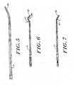
- the distal end 36 of the introducer needle 14may take on other configurations as well, such as a 30° curved distal end 36 ( FIG. 5 ), or a curved distal end 36 taking the shape of a hook ( FIGS. 6 and 7 ).
- a hook-shaped distal end 36may be formed as shown in FIGS. 6 and 7 .
- the hook shapemay be formed by creating a first curve 38 in the distal-most region of the introducer needle.
- a second curve 40is formed proximally to the first curve 38, in the same plane as the first curve 38, but in the opposite direction from the first curve 38.
- FIG. 7wherein the needle of FIG. 6 is rotated 90°, the hook is provided with a curve 42 in a third direction which is in a plane perpendicular to the plane in which the first 38 and second 40 curves are formed.
- FIGS. 8 through 17 and 19 through 23illustrate various embodiments and positions of suture grasping elements useful with the suture retrograder of the invention.
- a suture grasping element 16 having a first jaw 50 and a second jaw 52is illustrated in FIG. 8 .
- the first jaw 50is substantially straight and has a pod 54 located on its distal end 56.
- the exemplary pod 54is a cylindrical structure which extends from the first jaw 50 toward the second jaw 52.
- the pod 54may have a height of about 254 ⁇ m to 2.54 mm (0.010 to 0.100 inch), and preferably about 508 ⁇ m (0.020 inch). In practice, the pod may be provided on either or both jaws.
- the second jaw 52includes at least two segments 58, 60.
- the first, angled segment 58angles away from the first jaw 50.
- the first segment 58has a proximal end 62 which is in proximity to the first jaw 50, and a distal end 64 which is spaced apart from the first jaw 50.
- the angle between the first segment 58 and the first jaw 50is preferably in a range between about 15° and 45°.
- the first segment 58is linear and forms an angle of approximately 25° with the first jaw 50. It will be understood, however, that other second jaw 52 configurations may be used within the scope of the invention.
- the second segment 60 of the second jaw 52extends distally from the first segment 58 and is therefore spaced apart from the first jaw 50.
- the second segment 60is substantially linear and substantially parallel to the first jaw 50. Accordingly, the second segment 60 is spaced apart from the first jaw 50 along its length.
- the spacing between the pod 54 and the second segment 60is generally in the range of about 508 ⁇ m to 6.35 mm (0.020 to 0.250 inch), and is most preferably about 2.54 mm (0.100 inch).
- the spaced-apart position of the first 50 and second 52 jaws as shown in FIG. 8is referred to herein as the "open" position.
- the flexible suture grasping element 16is biased to the open position and achieves that position when the suture grasping element 16 is fully extended from the introducer needle 14.
- Recessed regions 66, 68may be provided on the first 50 and second 52 jaws, respectively. Recessed region 68 on the second jaw 52 is located at the distal end of the second segment 60 and extends proximally over approximately half the length of the second segment 60. Recessed region 66 on the first jaw 52 is provided adjacent to the pod 54. The recessed regions 66, 68 are arranged to provide an area wherein, when the jaws 50, 52 are pushed together (the "closed" position), a suture may be slidably retained.
- the suture grasping structure 16may be made from any flexible material suitable for surgical use including metals such as stainless steel or super elastic nickel-titanium (Nitinol) or plastic materials having elastic properties such as polyester, polypropylene or nylon.
- the suture grasping structure 16is formed from nickel-titanium tubing.
- the suture grasping structure 16may also include a cut-out portion 51 wherein approximately half of the flexible tubing is cut away. The cut-out portion 51 preferably corresponds to a region of the flexible tubing that travels within the curved distal portion 36 of the introducer needle 14.
- the jaws 50, 52preferably are formed from a single piece of tubing.
- the pod 54may also be integrally formed from the same piece of tubing.
- FIG. 8Aillustrates the formation of the jaws 50, 52 and the pod 54 from a single piece of hypodermic needle tubing.
- the tubinghas been machined, preferably by electric discharge machining ("EDM"), horizontally along the longitudinal axis 53 to separate two tines corresponding the first 50 and second 52 jaws, and to create the recessed regions 66, 68.
- EDMelectric discharge machining
- the second jaw 52may be fully formed by bending the tine corresponding to second jaw 52 into the form shown in and described with respect to FIG. 8 .
- a vertical cut 55is also made in the tubing to separate a tubular portion 57 corresponding to the distal pod 54.
- This tubular portion 57may be formed into the distal pod 54 shown in FIG. 8 by rotating the tubular portion 57 approximately 90° in a counter-clockwise direction about the point 59.
- the vertical cut 55is angled by approximately 5° so that the tubular portion may be rotated slightly more than 90°.
- the two-jawed suture grasping device 16 of FIG. 8may also be formed with additional angles 67, 69 as shown in FIG. 8B .
- Angle 67is provided in the first segment 58 of the second jaw 52 and angle 69 is provided in the first jaw 50.
- the anglesare oriented in the same direction and may range from about 10° to 60°. Furnishing the jaws 50, 52 with additional angles 67, 69 allows for greater curvature in the distal portion 36 of the inserter needle 14 and results in a greater angular range of operation for the suture grasping device as a whole.
- the angles 67, 69may be roughly equivalent, through it is preferred that angle 67 be greater than angle 69 to provide greater clearance between the jaws 50, 52 in the open position.
- the suture grasping device 10is shown with the suture grasping element 16 in the open, extended position.
- the actuator 18is located in its second, or distal-most, position and the linking member 20, which connects the actuator 18 to the suture grasping element 16, is also in its distal-most position.
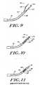
- the suture grasping element 16extends beyond the distal end 36 of the hollow introducer needle 14 in its open position as shown in FIG. 9 .
- the suture grasping element 16When the suture grasping element 16 is fully extended, it extends approximately by a distance of about 6.35 mm to 12.7 mm (0.250 to 0.500 inch) beyond the distal end 36 of the introducer needle 14.
- the distance by which the element 16 extendsmay be varied by a person of ordinary skill in the art depending upon the circumstances under which the device of the invention is used. However, a preferred distance is about 9.525 mm (0.375 inch) when the actuator 18 is in the second, distal-most position.
- the angled first segment 58 of the second jaw 52contacts the inner wall 70 of the distal end 36 of the hollow introducer needle 14, and the second jaw 52 is forced towards the first jaw 50.
- the second jaw 52contacts the pod 54 on the first jaw 50 (shown in FIG. 10 ), thereby achieving a closed state and defining a region 72 between the jaws 50, 52 wherein a suture may effectively be retained.
- the suture retaining region 72extends beyond the distal end 36 of the introducer needle 14 by a distance of about 0.050 to 12.7 mm (0.500 inch), and preferably about 3.175 mm (0.125 inch), so that a retained suture may be slidably manipulated by the suture grasping device 10.
- the actual distance by which the element 16 extendsmay, of course, be varied by a person of ordinary skill in the art depending upon the circumstances under which the device of the invention is used.
- the actuator 18When the actuator 18 is moved all of the way to its first, proximal-most position, the suture grasping element 16 is fully retracted within the distal end 36 of the introducer needle 14.
- the fully retracted position of the suture grasping element 16, and the suture grasping region 72,is best seen by reference to FIG. 11 .
- FIGS. 11A, 11B and 11CThe extended, intermediate and retracted positions of the suture grasping element 16 having additional angles 67, 69 (shown in FIG. 8B ) are illustrated in FIGS. 11A, 11B and 11C , respectively.
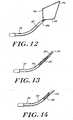
- the suture grasping device of the inventionmay utilize other suture grasping element configurations, such as the wire loop 74 suture grasping element shown in FIGS. 12-14 .
- the wire loop 74may be made from a flexible material suitable for surgical use, including metals such as stainless steel or super elastic nickel-titanium (Nitinol) or plastic materials having elastic properties such as polyester, polypropylene or nylon.
- the wire loop 74is constructed from Nitinol.
- the wire loop 74may be formed from a single, continuous wire element, or it may be formed using two wire elements joined at a distal portion of each.
- the wire loop 74 of FIG. 12has two leg segments 76, 78. Beginning at a proximal end of the wire loop 74 and moving distally, the leg segments diverge from one another, reach a point of maximum width there-between, then converge to meet at a distal end of the wire loop 74.
- the wire loop 74thereby takes on a quadrangular or diamond shape when extended, as shown in FIG. 12 . In its extended position, the wire loop 74 has a maximum width between the leg segments 76, 78 in the range of approximately 2.54 mm to 20.32 mm (0.100 to 0.800 inch), and more preferably about 10.16 mm (0.400 inch)
- the wire loop 74may also be retracted to an intermediate position as shown in FIG. 13 .
- the actuator 18As the actuator 18 is moved from its second or distal-most position to the intermediate position, the diverging portions of the two leg segments 76, 78 contact the inner wall 70 of the distal end 36 of the hollow introducer needle 14. This causes the quadrangular shaped wire loop 74 to compress, or fold up, as it is retracted into the introducer needle 14.
- the actuator 18reaches the intermediate position, a small portion of the wire loop 74 remains extended beyond the distal end 36 of the introducer needle 14 and thereby defines a region 80 within the loop 74 where a suture may be retained. The retained suture may then be manipulated by the suture grasping device 10.
- the width of the wire loop 74 illustrated in FIG. 13should be sufficient to slidably retain a suture within the wire loop 74.
- This widthis generally in the range of about 0,508 to 6,35 mm (0.020 to 0.250 inch) and more preferably is approximately 1,71 mm (0.0675 inch).
- the loop 74may generally extend approximately 1,71 to 6,35 mm (0.0675 to 0.250 inch), and more preferably extends 3,18 mm (0.125 inch).
- the suture grasping device of the inventionmay also utilize a two member suture grasping element 92 as illustrated in FIGS. 15-17 .
- the suture grasping element 92consists of two wire-like members 94, 96.
- the first wire-like member 94has a transverse hooked end 98 which is curved toward the second wire-like member 96, the curve being formed in a plane that is substantially transverse to the first wire-like member 94.
- the hooked end 98may be formed on either or both of the wire-like members 94, 96.
- FIG. 15illustrates the two-member suture grasping element 92 in the fully extended, open position.
- both wire-like members 94, 96are flexible and articulatable.
- the wire-like membersare constructed from nickel-titanium (Nitinol).
- the spacing between the transverse hooked end 98 and the second wire-like member 96 in the open positionis generally in the range of about 1,27 to 12,7 mm (0.050 to 0.500 inch), and is preferably about 6,35 mm (0.250 inch).
- the wire-like members 94, 96extend a distance of about 6,35 to 12,7 mm (0.250 to 0.500 inch) beyond the distal end of the introducer needle 14.
- a preferred extension distanceis about 9,525 mm (0.375 inch).
- the two-member suture grasping element 92is shown in the partially retracted, intermediate position in FIG. 16 .
- the hooked end 98 of the first wire-like member 94contacts the second wire-like member, and creates a retaining region 90 between the two wire like members where a suture thread may be slidably retained.
- the suture retaining region 90extends beyond the distal end 36 of the introducer needle 14 by a distance of about 1.27 mm to 12.7 mm (0.050 to 0.500) inch, and preferably about 3.175 mm (0.125 inch).
- the width of the suture retaining region 90should be sufficient to slidably retain a suture between the wire-like members 94, 96.
- This widthis generally in the range of about 0.508 mm to 6.35 mm (0.020 to 0.250 inch), and more preferably is approximately 1.702 mm (0.067 inch).
- FIG. 17illustrates the two member suture grasping element in the fully retracted, closed position.
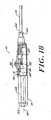
- detentsmay be provided to lock the suture grasping device 10 in the fully retracted and intermediate positions. These detents may suitably be provided by forming protruberances 82, 84 on the interior of the housing 12 corresponding to the fully retracted and intermediate positions respectively.
- a biased member 86 attached to the transverse member 32 of the actuator 18has a recess 88 which corresponds to the shape of the protuberances 82, 84. Accordingly, when the actuator 18 passes into the first or intermediate position, a detent is achieved.
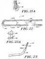
- FIGS. 19-23illustrate an alternate embodiment of the suture grasping element 116 of the surgical device 100 of the present invention.
- the suture grasping element 116comprises a substantially U-shaped hook element.
- suture grasping element 116may be made from a flexible material suitable for surgical use.
- suitable flexible materials of which the substantially U-shaped hook element 116 may be madeinclude a metal such as stainless steel, or a shape memory metal alloy such as super elastic nickel titanium, or a plastic having elastic properties such as polyester, polypropylene or nylon.
- the substantially U-shaped hook element 116is made of either super elastic nickel titanium or stainless steel.
- the surgical device 100 of the present inventionincludes similar internal components and is operated by a surgeon in the same way as the surgical device depicted in FIGS. 1-3 . Therefore, in this substantially U-shaped hook element embodiment of FIGS. 19-23 , the actuator element 18 communicates with the interior of the housing 12 through a transverse member 32 which is connected to a linking member 20 which, in turn, communicates with the substantially U-shaped suture grasping element 116.
- the substantially U-shaped hook element 116is also selectively movable among a fully retracted position wherein the actuator element 18 is closest to the distal end 24 of the housing 12, a fully extended position wherein the actuator element is closest to the proximal end 22 of the housing, and an intermediate position wherein the actuator element is selectively positioned at a location between the fully retracted and fully extended positions. It should be noted that the intermediate position of the substantially U-shaped hook element 116 can correspond to any position between the fully retracted and fully extended positions of the substantially U-shaped hook element.
- the actuator element 18may also engage detents at each of a rear position corresponding to the fully retracted position of the substantially U-shaped hook element 116, an intermediate position corresponding to the intermediate position of the substantially U-shaped hook element and a forward position corresponding to the fully extended position of the substantially U-shaped hook element.
- the detentsmay be provided similarly to the detents shown and discussed with respect to FIG. 18 .
- the detentsonce achieved, can be disengaged and the actuator element 18 can be moved, by pressing the actuator downwardly against a sidewall of the housing 12.
- the actuator element 18may be biased away from the sidewall of the housing by means such as a spring mechanism (not shown).
- the U-shaped hook element 116includes first and second opposed legs 190, 192 which are joined together by a curved connector segment 194.
- the second leg 192may include a proximal segment 192a which is separated from second leg 192 by a gap 193.
- the first leg 190is longer than the second leg 192.
- the second leg 192In the fully extended position, shown in FIGS. 19, 19A and 23 , the second leg 192 fully protrudes from the distal end 36 of the introducer needle 14 such that gap 193 defines an opening into the space within the U-shaped hook element 116 defined by the first and second legs 190, 192.
- the gap 193may have dimensions in the range of about 2.032 mm to 5.08 mm (0.080 inches to 0.200 inches).
- first leg 190 and the second leg 192although shown in FIG.22 as being parallel to one another, need not be parallel in order for this embodiment to be effective. Also, the spacing between the first and second legs 190, 192 may vary depending upon the requirements of a given application. Generally, however, first and second legs 190, 192 should be spaced apart from each other by a distance D in the range of about 0.8128 mm to 1.143 mm (0.032 inches to 0.045 inches).
- the width W of the first leg 190 and the second leg 192may vary within ranges that will be appreciated by one of ordinary skill in the art.
- First and second legs 190, 192may have the same or different widths.
- the width Wis in the range of about 0.381 mm to 0.762 mm (0.015 inches to 0.030 inches).
- the curved connector segment 194 of the hook element 116is shown in FIG. 22 as a substantially semi-circular element.
- the curved connector segment 194can be a substantially oval or substantially elliptical element.
- the first leg 190 and the second leg 192 of the substantially U-shaped hook element 116have a substantially rectangular cross section. That is, the width W of each of first and second legs 190, 192 is greater than the height H of the legs. Generally, the width W is in the range of about 0.381 mm to 0.762 mm (0.015 inches to 0.030 inches), while the height H is in the range of about 203.2 mm to 304.8 mm (0.008 inches to 0.012 inches).
- the substantially U-shaped hook element 116may be configured to have dimensions other than those noted above.
- the rectangular cross sectional relationship between the first and second legs 190, 192 of the substantially U-shaped hook element 116, when combined with the shape memory metal alloy or stainless steel construction of the hook element,allows for an advantageous hook design.
- this designconstrains bending of the substantially U-shaped hook element 116 to one plane and prevents rotation of the substantially U-shaped hook element as it exits the introducer needle 14, thus avoiding problems of tissue entanglement and hook deformation as the hook element is retracted into the introducer needle.
- This designalso allows for the substantially U-shaped hook element 116 to bend about a long side of the substantially U-shaped hook element.
- the substantially U-shaped hook element 116is in communication with the actuator element 18 through, among other things, a linking member 20.
- the linking memberpreferably extends from the transverse member 32 in the interior of the housing 12 through the interior of the hollow introducer needle 14 to communicate with the suture grasping hook element 116.
- the hollow introducer needle 14has a proximal end 34, which is connected to the distal end 24 of the housing 12, and a distal end 36.
- the introducer needle 14may have a generally hook shaped distal end; however, the surgical device 100 may also support an introducer needle that has an alternate design including, but not limited to, a generally corkscrew design.
Landscapes
- Health & Medical Sciences (AREA)
- Life Sciences & Earth Sciences (AREA)
- Surgery (AREA)
- Heart & Thoracic Surgery (AREA)
- Engineering & Computer Science (AREA)
- Biomedical Technology (AREA)
- Nuclear Medicine, Radiotherapy & Molecular Imaging (AREA)
- Medical Informatics (AREA)
- Molecular Biology (AREA)
- Animal Behavior & Ethology (AREA)
- General Health & Medical Sciences (AREA)
- Public Health (AREA)
- Veterinary Medicine (AREA)
- Surgical Instruments (AREA)
Description
- The invention relates to surgical instruments for grasping a suture or similar ligature within a patient's body. More particularly, the invention relates to suture grasping devices suitable for grasping a length of suture and drawing or pulling the suture through tissue in either open or closed surgical settings.
- A variety of devices and methods for grasping free suture portions or passing suture material through tissue are known in the art.
- One method for passing a suture end through tissue involves attaching the suture end to a needle. The needle can then be passed through the tissue using a needle manipulating device. Once passed through the tissue, a separate device, known as a retrograder, may be employed to retrieve or otherwise manipulate the needle and suture.
- In other methods, sharpened needle tips having suture grasping structures located within or near the needle tip may be used to grasp a suture, then penetrate the tissue to leave the suture end on the far side of the tissue where it can be grasped for further manipulation. Or, such a device may be used to penetrate the tissue first, grasp a suture on the far side of the tissue, and pull the suture back through the tissue.
- The suture grasping elements employable in such devices can have various configurations.
U.S. Patent No. 5,569,269 discloses the use of two wire-like elements, one of which has a hook-shaped configuration.U.S. Patent No. 5,496,335 discloses a suture grasping element having forcep jaws with sharpened tips.U.S. Patent No. 5,501,692 discloses a suture grasping element in the form of a looped wire. - The known devices suffer from some drawbacks. In closed surgery, especially in arthroscopic surgery involving a joint such as a knee or shoulder, space and visibility constraints at the surgical site render it difficult to fully extend a suture grasping device to easily grasp a suture. Thus, it can be difficult to locate and grasp a portion of a suture during closed surgical procedures using the above described devices.
- Also, because many of these devices have sharp edges that help to grasp the suture, there is a risk that the suture material will be cut while performing the desired suture manipulation at the surgical site. Likewise, some known suture grasper devices have grasping elements that can become caught or entangled in soft tissue during surgery. This entanglement, in turn, can lead to the permanent deformation of the grasping element and/or the unintentional damaging of tissue.
- The present invention provides a grasping device comprising: an elongate housing having a proximal end, a distal end, a sidewall disposed between the proximal and distal ends and a longitudinal axis; a hollow introducer needle having a proximal end attached to the distal end of the housing, and an open distal end having a tissue penetrating edge; a suture grasping element disposed within the open distal end of the introducer needle, the suture grasping element being selectively movable between at least extended and retracted positions; and an actuator element slidably mounted on the sidewall of the housing, the actuator being effective to move the suture grasping element between extended and retracted positions; characterized in that: the actuator element is movable among a first position in which the suture grasping element is fully retracted within the introducer needle, an intermediate position in which the suture grasping element is partially extended from the introducer needle and a second position in which the suture grasping element is fully extended from the introducer needle, and wherein a biased detent means is provided in the housing for releasable locking the actuator element in at least the first and intermediate positions.
US 5653716 discloses a suture manipulating instrument including an inner movable assembly having an elongated element which terminates in grasping members. The elongated element is embedded in a plunger which terminates at its proximal end in an enlarged head or handle.- Moreover, the actuator element may engage detents at the extended position in order to lock the suture grasping element in place at that positions.
- In one embodiment, the suture grasping element comprises two jaws. A first jaw includes a pod located on a distal end thereof, while a second jaw is movable between opened and closed positions. In the closed position, the pod contacts a distal portion of the second jaw in a manner sufficient to retain a suture between the jaws.
- In another embodiment, the suture grasping element comprises a compressible, substantially diamond-shaped wire loop. This structure is also movable among extended, partially retracted, and fully retracted positions. When the actuator is moved from the extended position to the intermediate position, the wire loop compresses and is partially retracted into the inner bore of the introducer needle. In this position, a portion of the loop that is effective to retain a suture remains extended from the introducer needle.
- In still another embodiment, the suture grasping element consists of two wire-like members with at least one of the members having a substantially transverse hook formed on its distal end. In the extended position, the distal portions of the wire-like members are spaced apart. As the actuator is moved to the intermediate position, the substantially transverse hook contacts the other wire-like members so as to form a closed region between the members capable of slidably retaining a suture.
- In yet another embodiment, the suture grasping element is in the form of a U-shaped hook element having first and second legs, wherein the first leg is larger than the second leg. The first leg is permanently disposed within the introducer needle. The second leg has a proximal end that is disposed within the introducer needle when the U-shaped hook element is in the fully retracted position and in the partially extended position. When the actuator is in the fully extended position, the second leg is disposed outside of the introducer needle so as to define an opening into a space within the hook element defined by the longer and shorter legs.
- In the above embodiments, the introducer needle may be oriented at a variety of angles with respect to a longitudinal axis of the housing. The introducer needle may also be hook-shaped or of a generally corkscrew design.
- The invention will be more fully understood by reference to the following detailed description when considered in conjunction with the accompanying drawings, in which:
FIG. 1 is an elevated view with a partial cut-away of a suture retrograder of the invention illustrating an open, fully extended suture grasping element;FIG. 2 is an elevated view with a partial cut-away of the suture retrograder ofFIG. 1 , illustrating the suture grasping element in a fully retracted, closed position;FIG. 3 is an elevated view, with a partial cut-away, of the suture retrograder ofFIG. 1 showing the suture grasping element in a partially retracted, intermediate position;FIG. 4 is a view of the introducer needle portion of the suture retrograder ofFIG. 1 , rotated 90°;FIG. 5 is an elevated view of one embodiment of an introducer needle portion of a suture retrograder constructed according to the present invention;FIG. 6 is an elevated view of another embodiment of an introducer needle portion of a suture retrograder in a partially formed state;FIG. 7 is a view of the introducer needle ofFIG. 6 , fully formed and rotated 90°;FIG. 8 is an elevated view of an open, extended suture grasping element having two jaw elements according to one embodiment of the invention;FIG. 8A is an elevated view of the suture grasping element ofFIG. 8 in a partially formed state;FIG. 8B is an elevated view of an open, extended suture grasping element having two jaws with additional angles;FIG. 9 is an elevated view of a distal portion of the suture retrograder ofFIGS. 1-3 illustrating the suture grasping element in a fully extended, open position;FIG. 10 is an elevated view, with a partial cut-away, of the distal end of the suture retrograder ofFIG. 9 , showing the suture grasping element in a partially retracted, intermediate position;FIG. 11 is an elevated view, with a partial cut-away, of the distal end of the suture retrograder ofFIG. 9 , showing the suture grasping element in a fully retracted, closed position;FIG. 11A is an elevated view of a distal portion of a suture retrograder of the invention having the suture grasping element ofFIG. 8B in a fully extended, open position;FIG. 11B is an elevated view, with a partial cut-away, of the distal end of the suture retrograder ofFIG. 11A , showing the suture grasping element in a partially retracted, intermediate position;FIG. 11C is an elevated view, with a partial cut-away, of the distal end of the suture retrograder ofFIG. 11A , showing the suture grasping element in a fully retracted, closed position;FIG. 12 is an elevated view of a distal portion of an alternative embodiment of the suture retrograder of the invention, illustrating a looped suture grasping element in a fully extended, open position;FIG. 13 is a perspective view, with a partial cut-away, of the embodiment ofFIG. 12 showing the looped suture grasping element in a partially retracted, intermediate position;FIG. 14 is a perspective view, with a partial cut-away, of the embodiment ofFIG. 12 showing the looped suture grasping element in a fully retracted, closed position;FIG. 15 is a perspective view of a distal portion of an additional embodiment of the suture retrograder of the invention, illustrating a suture grasping element having two wire-like members in a fully extended, open position;FIG. 16 is a perspective view, with a partial cut-away, of the embodiment ofFIG. 15 showing the suture grasping element having two wire-like members in a partially retracted, intermediate position;FIG. 17 is a perspective view, with a partial cut-away, of the embodiment ofFIG. 15 showing the suture grasping element having two wire-like elements in a fully retracted, closed position;FIG. 18 is an elevated view with, with a partial cut-away, of a handle portion of the suture retrograder device of the invention;FIG. 19 is an elevated view with a partial cut-away of an alterative embodiment of a suture retrograder of the present invention illustrating an open, fully extended suture grasping element;FIG. 19A is a front end view of the suture grasping element ofFIG. 19 ;FIG. 20 is an elevated view with a partial cut-away of the suture retrograder ofFIG. 19 , illustrating the suture grasping element in a partially retracted, intermediate position;FIG 20A is a front end view of the suture grasping element ofFIG. 20 ;FIG. 21 is an elevated view with a partial cut-away of the suture retrograder ofFIG. 19 , illustrating the suture grasping element in a fully retracted, closed position;FIG 21A is a front end view of the suture grasping element ofFIG. 21 ;FIG. 22 is an elevated view of a portion of the suture grasping element ofFIG. 19 in a partially formed state;FIG. 22A is a sectional view alongline 22A-22A of the suture grasping element ofFIG. 22 ; andFIG. 23 is a detail view of portion A of the suture retrograder ofFIG. 19 .- A
surgical device 10 of the invention for grasping or retrograding a suture or other ligature is illustrated inFIG. 1 . This exemplary instrument includes ahousing 12, ahollow introducer needle 14, asuture grasping element 16, anactuator 18 and a linkingmember 20 which connects theactuator 18 to thesuture grasping element 16. - The
exemplary housing 12 is elongate, generally cylindrical and has opposed proximal 22 and distal 24 ends. The shape and dimensions of the housing may be selected by a person of ordinary skill in the art to allow the housing to be suitably grasped by a surgeon in an operating environment. - The
actuator 18 is slidably mounted on aside wall 26 of thehousing 12. In the embodiment shown inFIG. 1 , the actuator has a rectangularly-shaped base and includes a series offlanges 28 having varying heights and angled surfaces so as to be easily manipulated in either of two directions by a surgeon's thumb. Theactuator 18 is mounted so as to slide in a direction substantially parallel to alongitudinal axis 30 of thehousing 12. Theactuator 18 is movable between a first position (shown inFIG. 2 ), wherein theactuator 18 is closest to theproximal end 22 of thehousing 12, and a second position (shown inFIG. 1 ), wherein theactuator 18 is closest to thedistal end 24 of thehousing 12. The actuator may also be selectively positionable at locations between the first and second positions as illustrated inFIG. 3 . - The
actuator 18 communicates with the interior of thehousing 12 through atransverse member 32. Thetransverse member 32 may extend through a rectangular slot (not shown) in theside wall 26 of thehousing 12 along which theactuator 18 slides. - The
transverse member 32 of theactuator 18 is connected to the linkingmember 20, which may be a rigid or semi-rigid rod. Preferably, the linkingmember 20 extends from thetransverse member 32 in the interior of thehousing 12 through the interior of thehollow introducer needle 14 to communicate with thesuture grasping element 16. - As shown in
FIG. 4 , thedistal end 36 of theintroducer needle 14 has anopening 44, which communicates with the interior ofhollow introducer needle 14. The edges of the opendistal end 46 are sharpened, coming to apoint 48 at the distal-most edge. The opendistal end 44 is thus suited to penetrate tissue. Thehollow introducer needle 14 has aproximal end 34, which is connected to thedistal end 24 of thehousing 12, and adistal end 36. - The
distal end 36 of the introducer needle may extend at various angles. For example, as shown inFIG. 1 , thedistal end 36 of theintroducer needle 14 is angled approximately 60° with respect to thelongitudinal axis 30 of thehousing 12. Thedistal end 36 of theintroducer needle 14 may take on other configurations as well, such as a 30° curved distal end 36 (FIG. 5 ), or a curveddistal end 36 taking the shape of a hook (FIGS. 6 and 7 ). - A hook-shaped
distal end 36 may be formed as shown inFIGS. 6 and 7 . As illustrated inFIG. 6 , the hook shape may be formed by creating a first curve 38 in the distal-most region of the introducer needle. Asecond curve 40 is formed proximally to the first curve 38, in the same plane as the first curve 38, but in the opposite direction from the first curve 38. Referring toFIG. 7 , wherein the needle ofFIG. 6 is rotated 90°, the hook is provided with acurve 42 in a third direction which is in a plane perpendicular to the plane in which the first 38 and second 40 curves are formed. FIGS. 8 through 17 and19 through 23 illustrate various embodiments and positions of suture grasping elements useful with the suture retrograder of the invention.- A
suture grasping element 16 having afirst jaw 50 and asecond jaw 52 is illustrated inFIG. 8 . Thefirst jaw 50 is substantially straight and has apod 54 located on its distal end 56. Theexemplary pod 54 is a cylindrical structure which extends from thefirst jaw 50 toward thesecond jaw 52. Generally, thepod 54 may have a height of about 254 µm to 2.54 mm (0.010 to 0.100 inch), and preferably about 508 µm (0.020 inch). In practice, the pod may be provided on either or both jaws. - The
second jaw 52 includes at least twosegments segment 58 angles away from thefirst jaw 50. Accordingly, thefirst segment 58 has aproximal end 62 which is in proximity to thefirst jaw 50, and adistal end 64 which is spaced apart from thefirst jaw 50. The angle between thefirst segment 58 and thefirst jaw 50 is preferably in a range between about 15° and 45°. In the exemplary embodiment ofFIG. 8 , thefirst segment 58 is linear and forms an angle of approximately 25° with thefirst jaw 50. It will be understood, however, that othersecond jaw 52 configurations may be used within the scope of the invention. - The
second segment 60 of thesecond jaw 52 extends distally from thefirst segment 58 and is therefore spaced apart from thefirst jaw 50. In the exemplary embodiment ofFIG. 8 , thesecond segment 60 is substantially linear and substantially parallel to thefirst jaw 50. Accordingly, thesecond segment 60 is spaced apart from thefirst jaw 50 along its length. The spacing between thepod 54 and thesecond segment 60 is generally in the range of about 508 µm to 6.35 mm (0.020 to 0.250 inch), and is most preferably about 2.54 mm (0.100 inch). The spaced-apart position of the first 50 and second 52 jaws as shown inFIG. 8 is referred to herein as the "open" position. The flexiblesuture grasping element 16 is biased to the open position and achieves that position when thesuture grasping element 16 is fully extended from theintroducer needle 14. - Recessed
regions region 68 on thesecond jaw 52 is located at the distal end of thesecond segment 60 and extends proximally over approximately half the length of thesecond segment 60. Recessedregion 66 on thefirst jaw 52 is provided adjacent to thepod 54. The recessedregions jaws - The
suture grasping structure 16 may be made from any flexible material suitable for surgical use including metals such as stainless steel or super elastic nickel-titanium (Nitinol) or plastic materials having elastic properties such as polyester, polypropylene or nylon. In the exemplary embodiment ofFIG. 8 , thesuture grasping structure 16 is formed from nickel-titanium tubing. Thesuture grasping structure 16 may also include a cut-out portion 51 wherein approximately half of the flexible tubing is cut away. The cut-out portion 51 preferably corresponds to a region of the flexible tubing that travels within the curveddistal portion 36 of theintroducer needle 14. - The
jaws pod 54 may also be integrally formed from the same piece of tubing.FIG. 8A illustrates the formation of thejaws pod 54 from a single piece of hypodermic needle tubing. In the stage of formation shown, the tubing has been machined, preferably by electric discharge machining ("EDM"), horizontally along thelongitudinal axis 53 to separate two tines corresponding the first 50 and second 52 jaws, and to create the recessedregions second jaw 52 may be fully formed by bending the tine corresponding tosecond jaw 52 into the form shown in and described with respect toFIG. 8 . - A
vertical cut 55 is also made in the tubing to separate a tubular portion 57 corresponding to thedistal pod 54. This tubular portion 57 may be formed into thedistal pod 54 shown inFIG. 8 by rotating the tubular portion 57 approximately 90° in a counter-clockwise direction about the point 59. Preferably, thevertical cut 55 is angled by approximately 5° so that the tubular portion may be rotated slightly more than 90°. - The two-jawed
suture grasping device 16 ofFIG. 8 may also be formed withadditional angles FIG. 8B .Angle 67 is provided in thefirst segment 58 of thesecond jaw 52 andangle 69 is provided in thefirst jaw 50. Generally, the angles are oriented in the same direction and may range from about 10° to 60°. Furnishing thejaws additional angles distal portion 36 of theinserter needle 14 and results in a greater angular range of operation for the suture grasping device as a whole. Theangles angle 67 be greater thanangle 69 to provide greater clearance between thejaws - Referring again to
FIG. 1 , thesuture grasping device 10 is shown with thesuture grasping element 16 in the open, extended position. Theactuator 18 is located in its second, or distal-most, position and the linkingmember 20, which connects theactuator 18 to thesuture grasping element 16, is also in its distal-most position. Correspondingly, thesuture grasping element 16 extends beyond thedistal end 36 of thehollow introducer needle 14 in its open position as shown inFIG. 9 . - When the
suture grasping element 16 is fully extended, it extends approximately by a distance of about 6.35 mm to 12.7 mm (0.250 to 0.500 inch) beyond thedistal end 36 of theintroducer needle 14. The distance by which theelement 16 extends may be varied by a person of ordinary skill in the art depending upon the circumstances under which the device of the invention is used. However, a preferred distance is about 9.525 mm (0.375 inch) when theactuator 18 is in the second, distal-most position. - As the
actuator 18 is moved from the second, distal-most position toward the first, proximal-most position, the angledfirst segment 58 of thesecond jaw 52 contacts theinner wall 70 of thedistal end 36 of thehollow introducer needle 14, and thesecond jaw 52 is forced towards thefirst jaw 50. As the actuator reaches an intermediate position, thesecond jaw 52 contacts thepod 54 on the first jaw 50 (shown inFIG. 10 ), thereby achieving a closed state and defining aregion 72 between thejaws actuator 18 is in the intermediate position, thesuture retaining region 72 extends beyond thedistal end 36 of theintroducer needle 14 by a distance of about 0.050 to 12.7 mm (0.500 inch), and preferably about 3.175 mm (0.125 inch), so that a retained suture may be slidably manipulated by thesuture grasping device 10. The actual distance by which theelement 16 extends may, of course, be varied by a person of ordinary skill in the art depending upon the circumstances under which the device of the invention is used. - When the
actuator 18 is moved all of the way to its first, proximal-most position, thesuture grasping element 16 is fully retracted within thedistal end 36 of theintroducer needle 14. The fully retracted position of thesuture grasping element 16, and thesuture grasping region 72, is best seen by reference toFIG. 11 . - The extended, intermediate and retracted positions of the
suture grasping element 16 havingadditional angles 67, 69 (shown inFIG. 8B ) are illustrated inFIGS. 11A, 11B and 11C , respectively. - The suture grasping device of the invention may utilize other suture grasping element configurations, such as the
wire loop 74 suture grasping element shown inFIGS. 12-14 . As with the two-jawsuture grasping element 16, thewire loop 74 may be made from a flexible material suitable for surgical use, including metals such as stainless steel or super elastic nickel-titanium (Nitinol) or plastic materials having elastic properties such as polyester, polypropylene or nylon. Preferably, thewire loop 74 is constructed from Nitinol. Thewire loop 74 may be formed from a single, continuous wire element, or it may be formed using two wire elements joined at a distal portion of each. - The
wire loop 74 ofFIG. 12 has twoleg segments wire loop 74 and moving distally, the leg segments diverge from one another, reach a point of maximum width there-between, then converge to meet at a distal end of thewire loop 74. Thewire loop 74 thereby takes on a quadrangular or diamond shape when extended, as shown inFIG. 12 . In its extended position, thewire loop 74 has a maximum width between theleg segments - Like the two-jaw
suture grasping element 16, thewire loop 74 may also be retracted to an intermediate position as shown inFIG. 13 . As theactuator 18 is moved from its second or distal-most position to the intermediate position, the diverging portions of the twoleg segments inner wall 70 of thedistal end 36 of thehollow introducer needle 14. This causes the quadrangular shapedwire loop 74 to compress, or fold up, as it is retracted into theintroducer needle 14. When theactuator 18 reaches the intermediate position, a small portion of thewire loop 74 remains extended beyond thedistal end 36 of theintroducer needle 14 and thereby defines aregion 80 within theloop 74 where a suture may be retained. The retained suture may then be manipulated by thesuture grasping device 10. In this partially retracted position, the width of thewire loop 74 illustrated inFIG. 13 should be sufficient to slidably retain a suture within thewire loop 74. This width is generally in the range of about 0,508 to 6,35 mm (0.020 to 0.250 inch) and more preferably is approximately 1,71 mm (0.0675 inch). Theloop 74 may generally extend approximately 1,71 to 6,35 mm (0.0675 to 0.250 inch), and more preferably extends 3,18 mm (0.125 inch). - Moving the
actuator 18 to its first, proximal-most position fully retracts thewire loop 74 within thedistal end 36 of theintroducer needle 14 as shown inFIG. 14 . - The suture grasping device of the invention may also utilize a two member
suture grasping element 92 as illustrated inFIGS. 15-17 . Thesuture grasping element 92 consists of two wire-like members like member 94 has a transversehooked end 98 which is curved toward the second wire-like member 96, the curve being formed in a plane that is substantially transverse to the first wire-like member 94. In general, thehooked end 98 may be formed on either or both of the wire-like members FIG. 15 illustrates the two-membersuture grasping element 92 in the fully extended, open position. In the illustrated embodiment, both wire-like members hooked end 98 and the second wire-like member 96 in the open position is generally in the range of about 1,27 to 12,7 mm (0.050 to 0.500 inch), and is preferably about 6,35 mm (0.250 inch). Fully extended, the wire-like members introducer needle 14. A preferred extension distance is about 9,525 mm (0.375 inch). - The two-member
suture grasping element 92 is shown in the partially retracted, intermediate position inFIG. 16 . In this position, thehooked end 98 of the first wire-like member 94 contacts the second wire-like member, and creates a retainingregion 90 between the two wire like members where a suture thread may be slidably retained. In this position, thesuture retaining region 90 extends beyond thedistal end 36 of theintroducer needle 14 by a distance of about 1.27 mm to 12.7 mm (0.050 to 0.500) inch, and preferably about 3.175 mm (0.125 inch). - In the partially retracted position, the width of the
suture retaining region 90 should be sufficient to slidably retain a suture between the wire-like members FIG. 17 illustrates the two member suture grasping element in the fully retracted, closed position.- Referring to
FIG. 18 , detents may be provided to lock thesuture grasping device 10 in the fully retracted and intermediate positions. These detents may suitably be provided by forming protruberances 82, 84 on the interior of thehousing 12 corresponding to the fully retracted and intermediate positions respectively. A biased member 86 attached to thetransverse member 32 of theactuator 18 has a recess 88 which corresponds to the shape of the protuberances 82, 84. Accordingly, when the actuator 18 passes into the first or intermediate position, a detent is achieved. FIGS. 19-23 illustrate an alternate embodiment of thesuture grasping element 116 of the surgical device 100 of the present invention. In this embodiment thesuture grasping element 116 comprises a substantially U-shaped hook element. Like the embodiments of the suture grasping elements described above with respect toFIGS. 1-17 ,suture grasping element 116 may be made from a flexible material suitable for surgical use. In this embodiment, suitable flexible materials of which the substantiallyU-shaped hook element 116 may be made include a metal such as stainless steel, or a shape memory metal alloy such as super elastic nickel titanium, or a plastic having elastic properties such as polyester, polypropylene or nylon. Preferably, the substantiallyU-shaped hook element 116 is made of either super elastic nickel titanium or stainless steel.- Additionally, in the embodiment of the surgical device 100 of the present invention that is shown in
FIGS. 19-23 , the surgical device includes similar internal components and is operated by a surgeon in the same way as the surgical device depicted inFIGS. 1-3 . Therefore, in this substantially U-shaped hook element embodiment ofFIGS. 19-23 , theactuator element 18 communicates with the interior of thehousing 12 through atransverse member 32 which is connected to a linkingmember 20 which, in turn, communicates with the substantially U-shapedsuture grasping element 116. - Thus, the substantially
U-shaped hook element 116 is also selectively movable among a fully retracted position wherein theactuator element 18 is closest to thedistal end 24 of thehousing 12, a fully extended position wherein the actuator element is closest to theproximal end 22 of the housing, and an intermediate position wherein the actuator element is selectively positioned at a location between the fully retracted and fully extended positions. It should be noted that the intermediate position of the substantiallyU-shaped hook element 116 can correspond to any position between the fully retracted and fully extended positions of the substantially U-shaped hook element. - Furthermore, in this embodiment of the surgical device 100 of the present invention, the
actuator element 18 may also engage detents at each of a rear position corresponding to the fully retracted position of the substantiallyU-shaped hook element 116, an intermediate position corresponding to the intermediate position of the substantially U-shaped hook element and a forward position corresponding to the fully extended position of the substantially U-shaped hook element. The detents may be provided similarly to the detents shown and discussed with respect toFIG. 18 . Moreover in this embodiment, the detents, once achieved, can be disengaged and theactuator element 18 can be moved, by pressing the actuator downwardly against a sidewall of thehousing 12. Also, in this embodiment, theactuator element 18 may be biased away from the sidewall of the housing by means such as a spring mechanism (not shown). - As shown in
FIGS. 19-23 , theU-shaped hook element 116 includes first and secondopposed legs FIGS. 22 and 23 , thesecond leg 192 may include aproximal segment 192a which is separated fromsecond leg 192 by agap 193. Preferably, thefirst leg 190 is longer than thesecond leg 192. - In the fully extended position, shown in
FIGS. 19, 19A and23 , thesecond leg 192 fully protrudes from thedistal end 36 of theintroducer needle 14 such thatgap 193 defines an opening into the space within theU-shaped hook element 116 defined by the first andsecond legs gap 193 may have dimensions in the range of about 2.032 mm to 5.08 mm (0.080 inches to 0.200 inches). - In the intermediate position, shown in
FIGS. 20 and 20A , theU-shaped hook element 116 is partially retracted within thedistal end 36 of theintroducer needle 14. In this intermediate position, thesecond leg 192 is partially retracted within theintroducer needle 14, thus closinggap 193. Further retraction of theU-shaped hook element 116 to the fully retracted position, shown inFIGS. 21 and21A , causes both the first and second legs 190,192 to be fully disposed within thedistal end 36 of theintroducer needle 14. - The
first leg 190 and thesecond leg 192, although shown inFIG.22 as being parallel to one another, need not be parallel in order for this embodiment to be effective. Also, the spacing between the first andsecond legs second legs - The width W of the
first leg 190 and thesecond leg 192, shown inFIG. 22A , may vary within ranges that will be appreciated by one of ordinary skill in the art. First andsecond legs hook element 116 is shown inFIG. 22 as a substantially semi-circular element. Depending on the spacing apart of thefirst leg 190 and thesecond leg 192, however, the curved connector segment 194 can be a substantially oval or substantially elliptical element. - The
first leg 190 and thesecond leg 192 of the substantiallyU-shaped hook element 116, as depicted inFIG. 22A , have a substantially rectangular cross section. That is, the width W of each of first andsecond legs U-shaped hook element 116 may be configured to have dimensions other than those noted above. - The rectangular cross sectional relationship between the first and
second legs U-shaped hook element 116, when combined with the shape memory metal alloy or stainless steel construction of the hook element, allows for an advantageous hook design. For example, this design constrains bending of the substantiallyU-shaped hook element 116 to one plane and prevents rotation of the substantially U-shaped hook element as it exits theintroducer needle 14, thus avoiding problems of tissue entanglement and hook deformation as the hook element is retracted into the introducer needle. This design also allows for the substantiallyU-shaped hook element 116 to bend about a long side of the substantially U-shaped hook element. - As noted above, the substantially
U-shaped hook element 116 is in communication with theactuator element 18 through, among other things, a linkingmember 20. The linking member preferably extends from thetransverse member 32 in the interior of thehousing 12 through the interior of thehollow introducer needle 14 to communicate with the suture graspinghook element 116. Thehollow introducer needle 14 has aproximal end 34, which is connected to thedistal end 24 of thehousing 12, and adistal end 36. As shown inFIGS. 19-21 , theintroducer needle 14 may have a generally hook shaped distal end; however, the surgical device 100 may also support an introducer needle that has an alternate design including, but not limited to, a generally corkscrew design. - It will be understood that the foregoing is only illustrative of the principles of the invention, and that various modifications can be made by those skilled in the art without departing form the scope of the claims.
Claims (12)
- A suture grasping device (10), comprising:an elongate housing (12) having a proximal end (22), a distal end (24), a sidewall (26) disposed between the proximal and distal ends and a longitudinal axis (30);a hollow introducer needle (14) having a proximal end (34) attached to the distal end of the housing, and an open distal end (36) having a tissue penetrating edge;a suture grasping element (16, 74, 92, 116) disposed within the open distal end of the introducer needle, the suture grasping element being selectively movable between at least extended and retracted positions; andan actuator element (18), the actuator being effective to move the suture grasping element (16, 74, 92, 116) between extended and retracted positions;characterized in that:the actuator element (18) is slidably mounted on the sidewall of the housing, and is movable among a first position in which the suture grasping element (16, 74, 92, 116) is fully retracted within the introducer needle, an intermediate position in which the suture grasping element is partially extended from the introducer needle and a second position in which the suture grasping element is fully extended from the introducer needle, and wherein a biased detent means is provided in the housing for releasably locking the actuator element in at least the first and intermediate positions.
- The device of claim 1, wherein the suture grasping element comprises:a first jaw (50) having a pod (54) located on a distal end (56) thereof, andan articulatable second jaw (52) movable between a closed position wherein a distal portion of the second jaw contacts the pod element on the first jaw in a manner sufficient to retain a suture between the jaws, and an open position wherein the second jaw is spaced apart from the first jaw.
- The device of claim 2, wherein when the actuator element is in the intermediate position, the suture grasping element is partially extended from the introducer needle and the second jaw is in the closed position, and when the actuator element is in the second position, the suture grasping element is fully extended from the introducer needle and the second jaw is in the open position.
- The device of claim 2, wherein the second jaw is biased to the open position and moves to the closed position from contact by the second jaw with an inner surface of the distal end of the hollow introducer needle.
- The device of claim 2, wherein the first jaw is substantially straight, and the second jaw consists of at last two segments including a first segment (58) forming an angle of between about 15° and 45° with the first jaw, and a second segment (60), that is distal to the first segment: substantially parallel to the first jaw and spaced apart from the first jaw.
- The device of claim 1, wherein the suture grasping element comprises a wire loop (74) having at a proximal end two leg segments (76, 78) that diverge from one another and then converge to meet one another at a distal end thereof, the suture grasping element substantially forming a diamond shape when the suture grasping element is fully extended.
- The device of claim 6, wherein the suture grasping element is made from a deformable material that is able to be compressed to fit within the inner bore of the hollow introducer needle in the retracted position and to expand to the substantially diamond-shaped configuration when in the extended position.
- The device of claim 1, wherein the suture grasping element comprises a first wire-like member (94) having a transverse hook (98) and a second wire-like member (96).
- The device of claim 8, wherein the first and second wire-like elements are spaced apart in the fully extended position, and the transverse hook contacts the second wire-like element in the intermediate, partially extended position in a manner sufficient to retain a suture between the first and second wire-like elements.
- The device of claim 1, wherein the suture grasping element comprises a substantially U-shaped hook element (116).
- The device of claim 10, wherein the suture grasping element further comprises a first leg (190) having the U-shaped hook element and a second, shorter leg (192a).
- The device of claim 1, wherein the sumre grasping element is sized and configured to form a closed region to slidably retain a suture in the intermediate position.
Priority Applications (2)
| Application Number | Priority Date | Filing Date | Title |
|---|---|---|---|
| EP10175567AEP2286730A3 (en) | 1997-08-06 | 1998-08-03 | Suture retrograder |
| EP10179204AEP2263557A3 (en) | 1997-08-06 | 1998-08-03 | Suture retrograder |
Applications Claiming Priority (3)
| Application Number | Priority Date | Filing Date | Title |
|---|---|---|---|
| US907223 | 1992-07-01 | ||
| US08/907,223US5910148A (en) | 1997-08-06 | 1997-08-06 | Suture retrograder |
| PCT/US1998/016196WO1999007291A1 (en) | 1997-08-06 | 1998-08-03 | Suture retrograder |
Related Child Applications (2)
| Application Number | Title | Priority Date | Filing Date |
|---|---|---|---|
| EP10179204ADivision-IntoEP2263557A3 (en) | 1997-08-06 | 1998-08-03 | Suture retrograder |
| EP10175567ADivision-IntoEP2286730A3 (en) | 1997-08-06 | 1998-08-03 | Suture retrograder |
Publications (3)
| Publication Number | Publication Date |
|---|---|
| EP1009290A1 EP1009290A1 (en) | 2000-06-21 |
| EP1009290A4 EP1009290A4 (en) | 2003-05-28 |
| EP1009290B1true EP1009290B1 (en) | 2014-05-28 |
Family
ID=25423720
Family Applications (3)
| Application Number | Title | Priority Date | Filing Date |
|---|---|---|---|
| EP10175567AWithdrawnEP2286730A3 (en) | 1997-08-06 | 1998-08-03 | Suture retrograder |
| EP10179204AWithdrawnEP2263557A3 (en) | 1997-08-06 | 1998-08-03 | Suture retrograder |
| EP98938331.0AExpired - LifetimeEP1009290B1 (en) | 1997-08-06 | 1998-08-03 | Suture retrograder |
Family Applications Before (2)
| Application Number | Title | Priority Date | Filing Date |
|---|---|---|---|
| EP10175567AWithdrawnEP2286730A3 (en) | 1997-08-06 | 1998-08-03 | Suture retrograder |
| EP10179204AWithdrawnEP2263557A3 (en) | 1997-08-06 | 1998-08-03 | Suture retrograder |
Country Status (4)
| Country | Link |
|---|---|
| US (2) | US5910148A (en) |
| EP (3) | EP2286730A3 (en) |
| AU (1) | AU8687898A (en) |
| WO (1) | WO1999007291A1 (en) |
Families Citing this family (289)
| Publication number | Priority date | Publication date | Assignee | Title |
|---|---|---|---|---|
| US6629984B1 (en)* | 1998-07-07 | 2003-10-07 | Kwan-Ho Chan | Surgical repair kit and its method of use |
| FR2768324B1 (en) | 1997-09-12 | 1999-12-10 | Jacques Seguin | SURGICAL INSTRUMENT FOR PERCUTANEOUSLY FIXING TWO AREAS OF SOFT TISSUE, NORMALLY MUTUALLY REMOTE, TO ONE ANOTHER |
| US6517552B1 (en)* | 1997-10-29 | 2003-02-11 | Arthrex, Inc. | Suture retriever |
| WO1999047050A2 (en)* | 1998-03-20 | 1999-09-23 | Scimed Life Systems, Inc. | Endoscopic suture systems |
| US8216256B2 (en) | 1999-04-09 | 2012-07-10 | Evalve, Inc. | Detachment mechanism for implantable fixation devices |
| AU770243B2 (en)* | 1999-04-09 | 2004-02-19 | Evalve, Inc. | Methods and apparatus for cardiac valve repair |
| US7226467B2 (en)* | 1999-04-09 | 2007-06-05 | Evalve, Inc. | Fixation device delivery catheter, systems and methods of use |
| US20040044350A1 (en) | 1999-04-09 | 2004-03-04 | Evalve, Inc. | Steerable access sheath and methods of use |
| US7811296B2 (en) | 1999-04-09 | 2010-10-12 | Evalve, Inc. | Fixation devices for variation in engagement of tissue |
| US6752813B2 (en) | 1999-04-09 | 2004-06-22 | Evalve, Inc. | Methods and devices for capturing and fixing leaflets in valve repair |
| US6524317B1 (en)* | 1999-12-30 | 2003-02-25 | Opus Medical, Inc. | Method and apparatus for attaching connective tissues to bone using a knotless suture anchoring device |
| US6533795B1 (en) | 2000-04-11 | 2003-03-18 | Opus Medical, Inc | Dual function suturing apparatus and method |
| US6616683B1 (en)* | 2000-05-02 | 2003-09-09 | Duke University | Method of making miniaturized surgical forceps |
| US6585730B1 (en)* | 2000-08-30 | 2003-07-01 | Opus Medical, Inc. | Method and apparatus for attaching connective tissues to bone using a knotless suture anchoring device |
| US6551330B1 (en) | 2000-09-21 | 2003-04-22 | Opus Medical, Inc. | Linear suturing apparatus and methods |
| US6652561B1 (en)* | 2000-10-13 | 2003-11-25 | Opus Medical, Inc | Method and apparatus for attaching connective tissues to bone using a perforated suture anchoring device |
| US7083638B2 (en)* | 2001-02-12 | 2006-08-01 | Arthrocare Corporation | Method and apparatus for attaching connective tissues to bone using a knotless suture anchoring device |
| WO2006130693A2 (en)* | 2005-06-01 | 2006-12-07 | Arthrocare Corporation | Knotless suture anchoring device having deforming section to accommodate sutures of various diameters |
| US6770076B2 (en)* | 2001-02-12 | 2004-08-03 | Opus Medical, Inc. | Method and apparatus for attaching connective tissues to bone using a knotless suture anchoring device |
| US6719776B2 (en)* | 2001-03-01 | 2004-04-13 | Ethicon Endo-Surgery, Inc. | Thumb pad actuator for an ultrasonic surgical instrument |
| US6547800B2 (en)* | 2001-06-06 | 2003-04-15 | Opus Medical, Inc. | Method and apparatus for attaching connective tissues to bone using a cortical bone anchoring device |
| US6605096B1 (en)* | 2001-07-20 | 2003-08-12 | Opus Medical Inc, | Percutaneous suturing apparatus and method |
| US6780198B1 (en)* | 2001-12-06 | 2004-08-24 | Opus Medical, Inc. | Bone anchor insertion device |
| US6855157B2 (en)* | 2002-02-04 | 2005-02-15 | Arthrocare Corporation | Method and apparatus for attaching connective tissues to bone using a knotless suture anchoring device |
| US7048754B2 (en)* | 2002-03-01 | 2006-05-23 | Evalve, Inc. | Suture fasteners and methods of use |
| US6984237B2 (en) | 2002-05-22 | 2006-01-10 | Orthopaedic Biosystems Ltd., Inc. | Suture passing surgical instrument |
| US7125413B2 (en)* | 2002-06-20 | 2006-10-24 | Scimed Life Systems, Inc. | Endoscopic fundoplication devices and methods for treatment of gastroesophageal reflux disease |
| US6770084B1 (en)* | 2002-06-26 | 2004-08-03 | Opus Medical, Inc. | Suture capture device |
| US7371245B2 (en)* | 2002-08-02 | 2008-05-13 | C R Bard, Inc | Transobturator introducer system for sling suspension system |
| US20040087978A1 (en)* | 2002-08-27 | 2004-05-06 | Velez Juan Manuel | Surgical fascia closure instrument, guide and method |
| US20050021055A1 (en)* | 2002-08-27 | 2005-01-27 | Souhail Toubia | Surgical closure instrument and methods |
| US20040073254A1 (en)* | 2002-10-08 | 2004-04-15 | Jeffrey Wyman | Suture retriever with in-line actuating handle |
| US7090690B2 (en)* | 2002-11-19 | 2006-08-15 | Arthrocare Corporation | Devices and methods for repairing soft tissue |
| US20040127915A1 (en)* | 2002-12-30 | 2004-07-01 | Fleenor Richard P. | Suture hoop system |
| US8187288B2 (en) | 2003-03-10 | 2012-05-29 | Boston Scientific Scimed, Inc. | Re-shapeable medical device |
| US8066718B2 (en)* | 2003-03-18 | 2011-11-29 | Depuy Mitek, Inc. | Expandable needle suture apparatus and associated handle assembly |
| US8585714B2 (en)* | 2003-03-18 | 2013-11-19 | Depuy Mitek, Llc | Expandable needle suture apparatus and associated handle assembly with rotational suture manipulation system |
| US10631871B2 (en) | 2003-05-19 | 2020-04-28 | Evalve, Inc. | Fixation devices, systems and methods for engaging tissue |
| US8444658B2 (en)* | 2003-07-07 | 2013-05-21 | Andrew C. Kim | Hydrodynamic suture passer |
| US7699857B2 (en)* | 2003-07-07 | 2010-04-20 | Andrew Kim | Hydrodynamic suture passer |
| US7682374B2 (en)* | 2003-10-21 | 2010-03-23 | Arthrocare Corporation | Knotless suture lock and bone anchor implant method |
| US7608092B1 (en) | 2004-02-20 | 2009-10-27 | Biomet Sports Medicince, LLC | Method and apparatus for performing meniscus repair |
| JP4212494B2 (en)* | 2004-03-02 | 2009-01-21 | 日本シャーウッド株式会社 | Medical suture tool |
| JP4774048B2 (en)* | 2004-05-14 | 2011-09-14 | エヴァルヴ インコーポレイテッド | Locking mechanism of fixing device engaged with tissue and tissue engaging method |
| EP1755461B1 (en) | 2004-06-16 | 2014-01-01 | Smith & Nephew, Inc. | Suture passing device |
| US7632284B2 (en)* | 2004-07-06 | 2009-12-15 | Tyco Healthcare Group Lp | Instrument kit and method for performing meniscal repair |
| US7883519B2 (en)* | 2004-07-06 | 2011-02-08 | Ran Oren | Suture manipulating instrument particularly useful with endoscopes |
| US20060020274A1 (en)* | 2004-07-23 | 2006-01-26 | Usgi Medical Inc. | Manipulatable grasping needle |
| EP3326543B1 (en)* | 2004-08-24 | 2019-07-24 | DePuy Mitek, LLC | Expandable needle suture apparatus and associated handle assembly with rotational suture manipulation system |
| WO2006037073A2 (en) | 2004-09-27 | 2006-04-06 | Evalve, Inc. | Methods and devices for tissue grasping and assessment |
| US8052592B2 (en) | 2005-09-27 | 2011-11-08 | Evalve, Inc. | Methods and devices for tissue grasping and assessment |
| JP2006102255A (en)* | 2004-10-06 | 2006-04-20 | Nippon Sherwood Medical Industries Ltd | Infusion line connection structure and connector having the connection structure |
| JP4669315B2 (en)* | 2005-04-21 | 2011-04-13 | 日本シャーウッド株式会社 | Organ fixture and organ fixture set |
| US7905903B2 (en) | 2006-02-03 | 2011-03-15 | Biomet Sports Medicine, Llc | Method for tissue fixation |
| US7905904B2 (en) | 2006-02-03 | 2011-03-15 | Biomet Sports Medicine, Llc | Soft tissue repair device and associated methods |
| US8361113B2 (en) | 2006-02-03 | 2013-01-29 | Biomet Sports Medicine, Llc | Method and apparatus for coupling soft tissue to a bone |
| US8088130B2 (en) | 2006-02-03 | 2012-01-03 | Biomet Sports Medicine, Llc | Method and apparatus for coupling soft tissue to a bone |
| US9801708B2 (en) | 2004-11-05 | 2017-10-31 | Biomet Sports Medicine, Llc | Method and apparatus for coupling soft tissue to a bone |
| US7749250B2 (en) | 2006-02-03 | 2010-07-06 | Biomet Sports Medicine, Llc | Soft tissue repair assembly and associated method |
| US7658751B2 (en) | 2006-09-29 | 2010-02-09 | Biomet Sports Medicine, Llc | Method for implanting soft tissue |
| US20060189993A1 (en) | 2004-11-09 | 2006-08-24 | Arthrotek, Inc. | Soft tissue conduit device |
| US8128658B2 (en) | 2004-11-05 | 2012-03-06 | Biomet Sports Medicine, Llc | Method and apparatus for coupling soft tissue to bone |
| US8303604B2 (en) | 2004-11-05 | 2012-11-06 | Biomet Sports Medicine, Llc | Soft tissue repair device and method |
| US9017381B2 (en) | 2007-04-10 | 2015-04-28 | Biomet Sports Medicine, Llc | Adjustable knotless loops |
| US7857830B2 (en) | 2006-02-03 | 2010-12-28 | Biomet Sports Medicine, Llc | Soft tissue repair and conduit device |
| US8118836B2 (en) | 2004-11-05 | 2012-02-21 | Biomet Sports Medicine, Llc | Method and apparatus for coupling soft tissue to a bone |
| US8840645B2 (en) | 2004-11-05 | 2014-09-23 | Biomet Sports Medicine, Llc | Method and apparatus for coupling soft tissue to a bone |
| US7909851B2 (en) | 2006-02-03 | 2011-03-22 | Biomet Sports Medicine, Llc | Soft tissue repair device and associated methods |
| US8137382B2 (en) | 2004-11-05 | 2012-03-20 | Biomet Sports Medicine, Llc | Method and apparatus for coupling anatomical features |
| US8298262B2 (en) | 2006-02-03 | 2012-10-30 | Biomet Sports Medicine, Llc | Method for tissue fixation |
| US8998949B2 (en) | 2004-11-09 | 2015-04-07 | Biomet Sports Medicine, Llc | Soft tissue conduit device |
| EP1845861B1 (en) | 2005-01-21 | 2011-06-22 | Mayo Foundation for Medical Education and Research | Thorascopic heart valve repair apparatus |
| US20060173468A1 (en)* | 2005-01-28 | 2006-08-03 | Marc Simmon | Obturator introducer with snare |
| US20060178564A1 (en)* | 2005-02-04 | 2006-08-10 | Jones Daniel B | Surgical rotary capture instrument for gastric band closing |
| EP1909670A4 (en)* | 2005-08-04 | 2010-05-26 | Bard Inc C R | Systems for introducing implants |
| JP2009515564A (en)* | 2005-08-04 | 2009-04-16 | シー・アール・バード・インコーポレイテツド | Pelvic implant system and method |
| JP4488981B2 (en)* | 2005-08-23 | 2010-06-23 | 日本シャーウッド株式会社 | Extractor and medical suture tool set |
| US20070049952A1 (en)* | 2005-08-30 | 2007-03-01 | Weiss Steven J | Apparatus and method for mitral valve repair without cardiopulmonary bypass, including transmural techniques |
| US8257371B2 (en)* | 2007-03-15 | 2012-09-04 | Suturenetics, Inc. | Limited access suturing devices, system, and methods |
| US8172801B2 (en)* | 2005-09-15 | 2012-05-08 | Boston Scientific Scimed, Inc. | Method for positioning a catheter guide element in a patient and kit for use in said method |
| WO2007059199A2 (en) | 2005-11-14 | 2007-05-24 | C.R. Bard, Inc. | Sling anchor system |
| JP4614451B2 (en)* | 2005-12-26 | 2011-01-19 | 日本シャーウッド株式会社 | Medical suture tool |
| US8696688B2 (en)* | 2006-02-02 | 2014-04-15 | Biomet Sports Medicine, Llc | Method and apparatus for passing a flexible strand |
| US9271713B2 (en) | 2006-02-03 | 2016-03-01 | Biomet Sports Medicine, Llc | Method and apparatus for tensioning a suture |
| US8506597B2 (en) | 2011-10-25 | 2013-08-13 | Biomet Sports Medicine, Llc | Method and apparatus for interosseous membrane reconstruction |
| US9149267B2 (en) | 2006-02-03 | 2015-10-06 | Biomet Sports Medicine, Llc | Method and apparatus for coupling soft tissue to a bone |
| US8251998B2 (en) | 2006-08-16 | 2012-08-28 | Biomet Sports Medicine, Llc | Chondral defect repair |
| US7959650B2 (en) | 2006-09-29 | 2011-06-14 | Biomet Sports Medicine, Llc | Adjustable knotless loops |
| US10517587B2 (en) | 2006-02-03 | 2019-12-31 | Biomet Sports Medicine, Llc | Method and apparatus for forming a self-locking adjustable loop |
| US11311287B2 (en) | 2006-02-03 | 2022-04-26 | Biomet Sports Medicine, Llc | Method for tissue fixation |
| US8652171B2 (en) | 2006-02-03 | 2014-02-18 | Biomet Sports Medicine, Llc | Method and apparatus for soft tissue fixation |
| US8652172B2 (en) | 2006-02-03 | 2014-02-18 | Biomet Sports Medicine, Llc | Flexible anchors for tissue fixation |
| US9468433B2 (en) | 2006-02-03 | 2016-10-18 | Biomet Sports Medicine, Llc | Method and apparatus for forming a self-locking adjustable loop |
| US8597327B2 (en) | 2006-02-03 | 2013-12-03 | Biomet Manufacturing, Llc | Method and apparatus for sternal closure |
| US8771352B2 (en) | 2011-05-17 | 2014-07-08 | Biomet Sports Medicine, Llc | Method and apparatus for tibial fixation of an ACL graft |
| US8574235B2 (en) | 2006-02-03 | 2013-11-05 | Biomet Sports Medicine, Llc | Method for trochanteric reattachment |
| US8562645B2 (en) | 2006-09-29 | 2013-10-22 | Biomet Sports Medicine, Llc | Method and apparatus for forming a self-locking adjustable loop |
| US9078644B2 (en) | 2006-09-29 | 2015-07-14 | Biomet Sports Medicine, Llc | Fracture fixation device |
| US8562647B2 (en) | 2006-09-29 | 2013-10-22 | Biomet Sports Medicine, Llc | Method and apparatus for securing soft tissue to bone |
| US8968364B2 (en) | 2006-02-03 | 2015-03-03 | Biomet Sports Medicine, Llc | Method and apparatus for fixation of an ACL graft |
| US9538998B2 (en) | 2006-02-03 | 2017-01-10 | Biomet Sports Medicine, Llc | Method and apparatus for fracture fixation |
| US11259792B2 (en) | 2006-02-03 | 2022-03-01 | Biomet Sports Medicine, Llc | Method and apparatus for coupling anatomical features |
| US8801783B2 (en) | 2006-09-29 | 2014-08-12 | Biomet Sports Medicine, Llc | Prosthetic ligament system for knee joint |
| US7615061B2 (en)* | 2006-02-28 | 2009-11-10 | Arthrocare Corporation | Bone anchor suture-loading system, method and apparatus |
| WO2007109062A2 (en)* | 2006-03-15 | 2007-09-27 | C.R. Bard, Inc. | Implants for the treatment of pelvic floor disorders |
| US8758405B2 (en) | 2006-03-23 | 2014-06-24 | Ethicon Endo-Surgery, Inc | Suture tensioning device |
| US20070249908A1 (en)* | 2006-04-24 | 2007-10-25 | Ifung Lu | Medical cannula and medical cannula system |
| US8211114B2 (en)* | 2006-04-24 | 2012-07-03 | Ethicon Endo-Surgery, Inc. | Medical instrument having a medical snare |
| US9138250B2 (en)* | 2006-04-24 | 2015-09-22 | Ethicon Endo-Surgery, Inc. | Medical instrument handle and medical instrument having a handle |
| US20070270639A1 (en)* | 2006-05-17 | 2007-11-22 | Long Gary L | Medical instrument having a catheter and having a catheter accessory device and method for using |
| US8876842B2 (en)* | 2006-05-22 | 2014-11-04 | Covidien Lp | Meniscal repair device |
| AU2007268046B2 (en)* | 2006-05-22 | 2012-08-16 | Covidien Lp | Method and apparatus for meniscal repair |
| ATE518484T1 (en)* | 2006-05-31 | 2011-08-15 | Covidien Ag | MEDICAL SUTURE INSTRUMENT WITH GRIPPER DEVICE |
| US8133258B2 (en) | 2006-08-03 | 2012-03-13 | Arthrocare Corporation | Method and apparatus for attaching connective tissues to bone using a knotless suture anchoring device |
| WO2008033950A2 (en) | 2006-09-13 | 2008-03-20 | C. R. Bard, Inc. | Urethral support system |
| US9918826B2 (en) | 2006-09-29 | 2018-03-20 | Biomet Sports Medicine, Llc | Scaffold for spring ligament repair |
| US8672969B2 (en) | 2006-09-29 | 2014-03-18 | Biomet Sports Medicine, Llc | Fracture fixation device |
| US11259794B2 (en) | 2006-09-29 | 2022-03-01 | Biomet Sports Medicine, Llc | Method for implanting soft tissue |
| US8500818B2 (en) | 2006-09-29 | 2013-08-06 | Biomet Manufacturing, Llc | Knee prosthesis assembly with ligament link |
| JP4536698B2 (en)* | 2006-10-05 | 2010-09-01 | 日本シャーウッド株式会社 | Medical suture tool |
| AU2014200115B2 (en)* | 2006-10-05 | 2016-01-28 | Coonahan, Timothy | Shape memory filament for suture management |
| US20080086147A1 (en)* | 2006-10-05 | 2008-04-10 | Knapp Thomas P | Shape memory filament for suture management |
| US9072514B2 (en) | 2006-10-05 | 2015-07-07 | Thomas P. Knapp | Shape memory filament for suture management |
| US8562629B2 (en)* | 2006-10-24 | 2013-10-22 | Arthrocare Corporation | Suture device having selective needle actuation and related method |
| ATE543441T1 (en) | 2006-11-07 | 2012-02-15 | Boston Scient Ltd | SUT RELEASE |
| JP4565576B2 (en)* | 2007-02-20 | 2010-10-20 | 日本シャーウッド株式会社 | Puncture needle assist tool |
| US8137381B2 (en)* | 2007-04-25 | 2012-03-20 | Arthrocare Corporation | Knotless suture anchor having discrete polymer components and related methods |
| US9314234B2 (en) | 2007-07-03 | 2016-04-19 | Ceterix Orthopaedics, Inc. | Pre-tied surgical knots for use with suture passers |
| US10441273B2 (en) | 2007-07-03 | 2019-10-15 | Ceterix Orthopaedics, Inc. | Pre-tied surgical knots for use with suture passers |
| US9861354B2 (en) | 2011-05-06 | 2018-01-09 | Ceterix Orthopaedics, Inc. | Meniscus repair |
| US8465505B2 (en) | 2011-05-06 | 2013-06-18 | Ceterix Orthopaedics, Inc. | Suture passer devices and methods |
| US20090062852A1 (en)* | 2007-08-29 | 2009-03-05 | Marino James F | Annular repair device and methods |
| US8888795B2 (en)* | 2007-09-07 | 2014-11-18 | Boston Scientific Scimed, Inc. | Suture passer |
| US7963972B2 (en)* | 2007-09-12 | 2011-06-21 | Arthrocare Corporation | Implant and delivery system for soft tissue repair |
| CA2703129C (en) | 2007-10-18 | 2016-02-16 | Neochord Inc. | Minimially invasive repair of a valve leaflet in a beating heart |
| US8206280B2 (en) | 2007-11-13 | 2012-06-26 | C. R. Bard, Inc. | Adjustable tissue support member |
| US20090216250A1 (en)* | 2008-02-27 | 2009-08-27 | Ralph Zipper | Device and Method for Carrying Material Through Tissue |
| US8579921B2 (en)* | 2008-06-18 | 2013-11-12 | Covidien Lp | Spring-type suture securing device |
| JP5185706B2 (en)* | 2008-06-24 | 2013-04-17 | 日本コヴィディエン株式会社 | Puncture needle assist tool |
| US8105343B2 (en)* | 2008-06-30 | 2012-01-31 | Arthrocare Corporation | Independent suture tensioning and snaring apparatus |
| WO2010019630A1 (en)* | 2008-08-13 | 2010-02-18 | Orizon Llc | Suture passer |
| US12419632B2 (en) | 2008-08-22 | 2025-09-23 | Biomet Sports Medicine, Llc | Method and apparatus for coupling anatomical features |
| US12245759B2 (en) | 2008-08-22 | 2025-03-11 | Biomet Sports Medicine, Llc | Method and apparatus for coupling soft tissue to bone |
| DE202008011769U1 (en)* | 2008-09-04 | 2008-11-06 | Karl Storz Gmbh & Co. Kg | Suture catcher for surgical sutures |
| AU2010228986B2 (en) | 2009-03-23 | 2015-03-26 | Linvatec Corporation | Suture passing apparatus and method |
| US8147505B2 (en)* | 2009-03-23 | 2012-04-03 | Arthrocare Corporation | Surgical instrument for manipulating surgical suture and methods of use |
| WO2010124129A1 (en)* | 2009-04-22 | 2010-10-28 | Pare Surgical, Inc. | Endoscopic tissue grasping apparatus and method |
| US8343227B2 (en) | 2009-05-28 | 2013-01-01 | Biomet Manufacturing Corp. | Knee prosthesis assembly with ligament link |
| US12096928B2 (en) | 2009-05-29 | 2024-09-24 | Biomet Sports Medicine, Llc | Method and apparatus for coupling soft tissue to a bone |
| US10426456B2 (en) | 2009-07-17 | 2019-10-01 | Pivot Medical, Inc. | Method and apparatus for re-attaching the labrum to the acetabulum, including the provision and use of a novel suture anchor system |
| US11246585B2 (en) | 2009-07-17 | 2022-02-15 | Stryker Puerto Rico Limited | Method and apparatus for attaching tissue to bone, including the provision and use of a novel knotless suture anchor system |
| US11197663B2 (en) | 2009-07-17 | 2021-12-14 | Stryker Puerto Rico Limited | Method and apparatus for attaching tissue to bone, including the provision and use of a novel knotless suture anchor system |
| US9149268B2 (en) | 2009-07-17 | 2015-10-06 | Pivot Medical, Inc. | Method and apparatus for attaching tissue to bone, including the provision and use of a novel knotless suture anchor system |
| US10238379B2 (en) | 2009-07-17 | 2019-03-26 | Pivot Medical, Inc. | Method and apparatus for attaching tissue to bone, including the provision and use of a novel knotless suture anchor system |
| US9179905B2 (en) | 2009-07-17 | 2015-11-10 | Pivot Medical, Inc. | Method and apparatus for re-attaching the labrum to the acetabulum, including the provision and use of a novel suture anchor system |
| US12232718B2 (en) | 2009-07-17 | 2025-02-25 | Stryker Puerto Rico Limited | Method and apparatus for attaching tissue to bone, including the provision and use of a novel knotless suture anchor system |
| US10136884B2 (en) | 2009-07-17 | 2018-11-27 | Pivot Medical, Inc. | Method and apparatus for attaching tissue to bone, including the provision and use of a novel knotless suture anchor system, including a retractable sheath |
| US10058319B2 (en) | 2009-07-17 | 2018-08-28 | Pivot Medical, Inc. | Method and apparatus for attaching tissue to bone, including the provision and use of a novel knotless suture anchor system, including a novel locking element |
| US9011454B2 (en) | 2009-11-09 | 2015-04-21 | Ceterix Orthopaedics, Inc. | Suture passer with radiused upper jaw |
| US9848868B2 (en) | 2011-01-10 | 2017-12-26 | Ceterix Orthopaedics, Inc. | Suture methods for forming locking loops stitches |
| US11744575B2 (en) | 2009-11-09 | 2023-09-05 | Ceterix Orthopaedics, Inc. | Suture passer devices and methods |
| US9211118B2 (en)* | 2009-11-16 | 2015-12-15 | Arthrocare Corporation | Suture passer |
| EP3305209B1 (en) | 2010-06-09 | 2025-01-08 | C.R. Bard Inc. | Instruments for delivering transfascial sutures and transfascial suture assemblies. |
| FR2962026B1 (en)* | 2010-07-02 | 2013-04-26 | Tornier Inc | SYSTEM FOR SUTURE |
| WO2012005671A1 (en)* | 2010-07-05 | 2012-01-12 | Laprotech Ab | Laparoscopic instrument |
| WO2015066620A1 (en) | 2010-09-10 | 2015-05-07 | Pivot Medical, Inc. | Method and apparatus for passing suture through tissue |
| US10098631B2 (en) | 2010-09-10 | 2018-10-16 | Pivot Medical, Inc. | Method and apparatus for passing suture through tissue |
| CA2813597C (en) | 2010-09-10 | 2019-09-03 | Pivot Medical, Inc. | Method and apparatus for passing suture through tissue |
| EP3150130B1 (en)* | 2010-10-13 | 2019-07-03 | Synthes GmbH | Apparatus for guiding a suture thread |
| EP2658480B1 (en) | 2010-12-29 | 2017-11-01 | Neochord Inc. | Exchangeable system for minimally invasive beating heart repair of heart valve leaflets |
| DE102012100083A1 (en)* | 2011-01-07 | 2012-09-13 | Z-Medical Gmbh & Co. Kg | thread gripper |
| US9913638B2 (en) | 2011-01-10 | 2018-03-13 | Ceterix Orthopaedics, Inc. | Transosteal anchoring methods for tissue repair |
| US8556916B2 (en) | 2011-02-14 | 2013-10-15 | Smith & Nephew, Inc. | Method and device for suture manipulation |
| EP2683304B1 (en) | 2011-03-10 | 2019-09-25 | Boston Scientific Scimed, Inc. | Flexible suturing instrument |
| US12329373B2 (en) | 2011-05-02 | 2025-06-17 | Biomet Sports Medicine, Llc | Method and apparatus for soft tissue fixation |
| CN103813757A (en) | 2011-06-01 | 2014-05-21 | 尼奥绰德有限公司 | Minimally Invasive Repair of heart valve leaflets |
| CN103796597A (en) | 2011-06-08 | 2014-05-14 | 苏图勒内蒂克斯股份有限公司 | Offset jaw suturing device, system, and methods |
| CN103917183A (en) | 2011-06-29 | 2014-07-09 | 皮沃特医疗公司 | Method and apparatus for re-attaching the labrum to the acetabulum, including the provision and use of a novel suture anchor system |
| US8888849B2 (en) | 2011-07-08 | 2014-11-18 | Smith & Nephew, Inc. | Soft tissue repair |
| US8882834B2 (en) | 2011-07-08 | 2014-11-11 | Smith & Nephew, Inc. | Soft tissue repair |
| US8951263B2 (en) | 2011-07-08 | 2015-02-10 | Smith & Nephew, Inc. | Orthopedic suture passer and method |
| US9357997B2 (en) | 2011-07-08 | 2016-06-07 | Smith & Nephew, Inc. | Suture passer and method |
| US9662105B2 (en) | 2011-07-08 | 2017-05-30 | Smith & Nephew, Inc. | Suture passer and method |
| US8801727B2 (en) | 2011-07-08 | 2014-08-12 | Smith & Nephew, Inc. | Orthopedic suture passer and method |
| US9636101B2 (en) | 2011-09-01 | 2017-05-02 | Arthrocare Corporation | Bone anchor having an integrated stress isolator |
| US8945177B2 (en) | 2011-09-13 | 2015-02-03 | Abbott Cardiovascular Systems Inc. | Gripper pusher mechanism for tissue apposition systems |
| US9492162B2 (en) | 2013-12-16 | 2016-11-15 | Ceterix Orthopaedics, Inc. | Automatically reloading suture passer devices and methods |
| US10524778B2 (en)* | 2011-09-28 | 2020-01-07 | Ceterix Orthopaedics | Suture passers adapted for use in constrained regions |
| WO2013062933A1 (en) | 2011-10-24 | 2013-05-02 | C.R. Bard, Inc. | Instruments for delivering transfascial sutures, transfascial suture assemblies and methods of transfascial suturing |
| US9357991B2 (en) | 2011-11-03 | 2016-06-07 | Biomet Sports Medicine, Llc | Method and apparatus for stitching tendons |
| US9924938B2 (en) | 2011-11-07 | 2018-03-27 | C.R. Bard, Inc. | Instruments for delivering transfascial sutures and methods of transfascial suturing |
| US9039721B2 (en) | 2011-11-07 | 2015-05-26 | C.R. Bard, Inc. | Instruments for delivering transfascial sutures and methods of transfascial suturing |
| US9078648B2 (en) | 2011-11-07 | 2015-07-14 | C.R. Bard, Inc. | Instruments for delivering transfascial sutures and methods of transfascial suturing |
| US9370350B2 (en) | 2011-11-10 | 2016-06-21 | Biomet Sports Medicine, Llc | Apparatus for coupling soft tissue to a bone |
| US9381013B2 (en) | 2011-11-10 | 2016-07-05 | Biomet Sports Medicine, Llc | Method for coupling soft tissue to a bone |
| US9314241B2 (en) | 2011-11-10 | 2016-04-19 | Biomet Sports Medicine, Llc | Apparatus for coupling soft tissue to a bone |
| US9259217B2 (en) | 2012-01-03 | 2016-02-16 | Biomet Manufacturing, Llc | Suture Button |
| US9023083B2 (en) | 2012-01-27 | 2015-05-05 | Arthrocare Corporation | Method for soft tissue repair with free floating suture locking member |
| US9364210B2 (en) | 2012-01-27 | 2016-06-14 | Arthrocare Corporation | Biased wedge suture anchor and method for soft tissue repair |
| US9226742B2 (en) | 2012-01-27 | 2016-01-05 | Arthrocare Corporation | Restricted wedge suture anchor and method for soft tissue repair |
| US9198649B2 (en) | 2012-01-27 | 2015-12-01 | Arthrocare Corporation | Rotating locking member suture anchor and method for soft tissue repair |
| US9034014B2 (en) | 2012-01-27 | 2015-05-19 | Arthrocare Corporation | Free floating wedge suture anchor for soft tissue repair |
| US10265062B2 (en)* | 2012-02-07 | 2019-04-23 | Arthrocare Corporation | Surgical instrument for manipulating and passing suture |
| GB2514505B (en) | 2012-02-07 | 2016-07-06 | Arthrocare Corp | Surgical instrument for manipulating and passing suture |
| WO2013122690A1 (en)* | 2012-02-16 | 2013-08-22 | Coopersurgical, Inc. | Suture passers |
| US9421544B2 (en) | 2012-02-29 | 2016-08-23 | Gary Chorng-Jyh Wang | Three-dimensional digital microfluidic system |
| US9855028B2 (en) | 2012-04-06 | 2018-01-02 | Arthrocare Corporation | Multi-suture knotless anchor for attaching tissue to bone and related method |
| US9451951B2 (en) | 2012-11-07 | 2016-09-27 | Arthrex, Inc. | Suture snare with retractable sleeve |
| US20140148826A1 (en)* | 2012-11-28 | 2014-05-29 | Pergolas, Llc | Minimally invasive surgical kit |
| US9801624B2 (en)* | 2012-12-28 | 2017-10-31 | Cook Medical Technologies Llc | Surgical suture device and methods of using the same |
| US9757119B2 (en) | 2013-03-08 | 2017-09-12 | Biomet Sports Medicine, Llc | Visual aid for identifying suture limbs arthroscopically |
| US9918827B2 (en) | 2013-03-14 | 2018-03-20 | Biomet Sports Medicine, Llc | Scaffold for spring ligament repair |
| US10292694B2 (en) | 2013-04-22 | 2019-05-21 | Pivot Medical, Inc. | Method and apparatus for attaching tissue to bone |
| JP5896322B2 (en)* | 2013-05-17 | 2016-03-30 | パナソニックIpマネジメント株式会社 | Sensor embedding device and sensor embedding system |
| US10258324B2 (en) | 2013-08-02 | 2019-04-16 | Covidien Lp | Devices, systems, and methods for providing surgical access and facilitating closure of surgical access openings |
| US10070851B2 (en) | 2013-08-02 | 2018-09-11 | Covidien Lp | Devices, systems, and methods for wound closure |
| US9848879B2 (en) | 2013-08-02 | 2017-12-26 | Covidien Lp | Devices, systems, and methods for wound closure |
| US9510823B2 (en) | 2013-08-02 | 2016-12-06 | Covidien Lp | Devices, systems, and methods for wound closure |
| US9247935B2 (en) | 2013-09-23 | 2016-02-02 | Ceterix Orthopaedics, Inc. | Arthroscopic knot pusher and suture cutter |
| US10245021B2 (en) | 2013-10-08 | 2019-04-02 | Applied Medical Technology, Inc | Magnetic U-stitch device |
| AU2014362199B2 (en) | 2013-12-12 | 2019-07-11 | Stryker Puerto Rico Limited | Method and apparatus for attaching tissue to bone, including the provision and use of a novel knotless suture anchor system |
| US10136886B2 (en) | 2013-12-20 | 2018-11-27 | Biomet Sports Medicine, Llc | Knotless soft tissue devices and techniques |
| US9572666B2 (en) | 2014-03-17 | 2017-02-21 | Evalve, Inc. | Mitral valve fixation device removal devices and methods |
| US10390943B2 (en) | 2014-03-17 | 2019-08-27 | Evalve, Inc. | Double orifice device for transcatheter mitral valve replacement |
| CN204951031U (en) | 2014-04-08 | 2016-01-13 | 赛特里克斯整形公司 | Ware device is worn to draw by suture |
| CN106456155A (en) | 2014-04-24 | 2017-02-22 | 史密夫和内修有限公司 | Suture passer |
| EP3134007A1 (en) | 2014-04-25 | 2017-03-01 | DePuy Synthes Products, Inc. | Flexible suture anchor threader and suture anchor kit |
| US9615822B2 (en) | 2014-05-30 | 2017-04-11 | Biomet Sports Medicine, Llc | Insertion tools and method for soft anchor |
| US9700291B2 (en) | 2014-06-03 | 2017-07-11 | Biomet Sports Medicine, Llc | Capsule retractor |
| US11246583B2 (en) | 2014-06-18 | 2022-02-15 | Boston Scientific Scimed, Inc. | Insertion devices, anchors, and methods for securing an implant |
| US9936943B1 (en) | 2014-08-07 | 2018-04-10 | Nicholas MANCINI | Suture passing surgical device with atraumatic grasper preventing accidental perforations |
| US10039543B2 (en) | 2014-08-22 | 2018-08-07 | Biomet Sports Medicine, Llc | Non-sliding soft anchor |
| US10188392B2 (en) | 2014-12-19 | 2019-01-29 | Abbott Cardiovascular Systems, Inc. | Grasping for tissue repair |
| US9955980B2 (en) | 2015-02-24 | 2018-05-01 | Biomet Sports Medicine, Llc | Anatomic soft tissue repair |
| US9974534B2 (en) | 2015-03-31 | 2018-05-22 | Biomet Sports Medicine, Llc | Suture anchor with soft anchor of electrospun fibers |
| US10524912B2 (en) | 2015-04-02 | 2020-01-07 | Abbott Cardiovascular Systems, Inc. | Tissue fixation devices and methods |
| US10376673B2 (en) | 2015-06-19 | 2019-08-13 | Evalve, Inc. | Catheter guiding system and methods |
| US10238494B2 (en) | 2015-06-29 | 2019-03-26 | Evalve, Inc. | Self-aligning radiopaque ring |
| US10667815B2 (en) | 2015-07-21 | 2020-06-02 | Evalve, Inc. | Tissue grasping devices and related methods |
| US10226245B2 (en) | 2015-07-21 | 2019-03-12 | Ceterix Orthopaedics, Inc. | Automatically reloading suture passer devices that prevent entanglement |
| US10413408B2 (en) | 2015-08-06 | 2019-09-17 | Evalve, Inc. | Delivery catheter systems, methods, and devices |
| WO2017059406A1 (en) | 2015-10-01 | 2017-04-06 | Neochord, Inc. | Ringless web for repair of heart valves |
| US10405853B2 (en) | 2015-10-02 | 2019-09-10 | Ceterix Orthpaedics, Inc. | Knot tying accessory |
| US10238495B2 (en) | 2015-10-09 | 2019-03-26 | Evalve, Inc. | Delivery catheter handle and methods of use |
| HK1210569A2 (en)* | 2015-12-17 | 2016-04-22 | 太津治有限公司 | Surgical device |
| US10603024B2 (en)* | 2016-06-17 | 2020-03-31 | Medos International Sarl | Devices, systems, and methods for moving tissue within a body |
| US10736632B2 (en) | 2016-07-06 | 2020-08-11 | Evalve, Inc. | Methods and devices for valve clip excision |
| US11071564B2 (en) | 2016-10-05 | 2021-07-27 | Evalve, Inc. | Cardiac valve cutting device |
| WO2018081374A1 (en) | 2016-10-31 | 2018-05-03 | Smith & Nephew, Inc. | Suture passer and grasper instrument and method |
| US10363138B2 (en) | 2016-11-09 | 2019-07-30 | Evalve, Inc. | Devices for adjusting the curvature of cardiac valve structures |
| US10398553B2 (en) | 2016-11-11 | 2019-09-03 | Evalve, Inc. | Opposing disk device for grasping cardiac valve tissue |
| US10426616B2 (en) | 2016-11-17 | 2019-10-01 | Evalve, Inc. | Cardiac implant delivery system |
| US10779837B2 (en) | 2016-12-08 | 2020-09-22 | Evalve, Inc. | Adjustable arm device for grasping tissues |
| US10314586B2 (en) | 2016-12-13 | 2019-06-11 | Evalve, Inc. | Rotatable device and method for fixing tricuspid valve tissue |
| US10213306B2 (en) | 2017-03-31 | 2019-02-26 | Neochord, Inc. | Minimally invasive heart valve repair in a beating heart |
| WO2018209313A1 (en) | 2017-05-12 | 2018-11-15 | Evalve, Inc. | Long arm valve repair clip |
| CA3129895A1 (en) | 2017-06-30 | 2019-01-03 | Wright Medical Technology, Inc. | Soft tissue repair instruments and techniques |
| KR102597762B1 (en) | 2017-12-14 | 2023-11-03 | 콘메드 코포레이션 | Suture passing device |
| CA3094990C (en) | 2018-03-23 | 2023-01-03 | Neochord, Inc. | Device for suture attachment for minimally invasive heart valve repair |
| US11129609B2 (en) | 2018-04-24 | 2021-09-28 | Covidien Lp | Devices, systems, and methods for providing surgical access and facilitating closure of surgical access openings |
| US11213288B2 (en) | 2018-05-02 | 2022-01-04 | Covidien Lp | Port site closure instrument |
| US11234690B2 (en) | 2018-05-02 | 2022-02-01 | Covidien Lp | Method and device for closing a port site incision |
| US11583269B2 (en) | 2018-05-04 | 2023-02-21 | Arch Day Design, Llc | Suture passing device |
| US11278274B2 (en) | 2018-05-04 | 2022-03-22 | Arch Day Design, Llc | Suture passing device |
| EP3787526B1 (en) | 2018-05-04 | 2023-04-19 | Arch Day Design, LLC | Suture passing device |
| US11173030B2 (en) | 2018-05-09 | 2021-11-16 | Neochord, Inc. | Suture length adjustment for minimally invasive heart valve repair |
| US11253360B2 (en) | 2018-05-09 | 2022-02-22 | Neochord, Inc. | Low profile tissue anchor for minimally invasive heart valve repair |
| WO2019222213A2 (en)* | 2018-05-15 | 2019-11-21 | Muffin Incorporated | Devices for placement and fixation of annuloplasty belt |
| US20210077091A1 (en)* | 2018-05-29 | 2021-03-18 | Smith & Nephew, Inc. | Suture passer with locking actuator |
| AU2019297353A1 (en)* | 2018-07-05 | 2021-01-21 | Smith & Nephew Asia Pacific Pte. Limited | Suture passing device and methods of use thereof |
| AU2019336254B2 (en) | 2018-09-07 | 2021-12-09 | Neochord, Inc. | Device for suture attachment for minimally invasive heart valve repair |
| US12102531B2 (en) | 2018-10-22 | 2024-10-01 | Evalve, Inc. | Tissue cutting systems, devices and methods |
| WO2020214818A1 (en) | 2019-04-16 | 2020-10-22 | Neochord, Inc. | Transverse helical cardiac anchor for minimally invasive heart valve repair |
| US11357517B1 (en) | 2019-04-25 | 2022-06-14 | Nirav H. Amin | System and method for creating graft tunnels in bone |
| US10667805B1 (en)* | 2019-05-17 | 2020-06-02 | Composite Surgical, LLC | Steerable suture retriever |
| JP7543391B2 (en) | 2019-07-15 | 2024-09-02 | エバルブ,インコーポレイティド | Method of Actuating Individual Proximal Elements |
| US11246586B2 (en)* | 2019-08-20 | 2022-02-15 | Arch Day Design, Llc | Instrument to manipulate and pass suture |
| CN114828758A (en)* | 2020-01-13 | 2022-07-29 | 史密夫和内修有限公司 | Surgical instrument for manipulating and threading sutures |
| WO2021146757A2 (en) | 2020-01-16 | 2021-07-22 | Neochord, Inc. | Helical cardiac anchors for minimally invasive heart valve repair |
| US12171486B2 (en) | 2020-05-06 | 2024-12-24 | Evalve, Inc. | Devices and methods for clip separation |
| US12414811B2 (en) | 2020-05-06 | 2025-09-16 | Evalve, Inc. | Devices and methods for leaflet cutting |
| US12178444B2 (en) | 2020-05-06 | 2024-12-31 | Evalve, Inc. | Clip removal systems and methods |
| US12048448B2 (en) | 2020-05-06 | 2024-07-30 | Evalve, Inc. | Leaflet grasping and cutting device |
| US12171485B2 (en) | 2020-05-06 | 2024-12-24 | Evalve, Inc. | Systems and methods for leaflet cutting using a hook catheter |
| US10973512B1 (en) | 2020-05-14 | 2021-04-13 | Composite Surgical, LLC | Steerable suture retriever |
| US11154295B1 (en) | 2020-05-14 | 2021-10-26 | Composite Surgical, LLC | Steerable suture retriever |
| EP4433129A1 (en) | 2022-01-04 | 2024-09-25 | TACC Inc | Vascular access line and implantation devices and methods |
| US20250017719A1 (en) | 2023-07-12 | 2025-01-16 | Integrity Medical Services Inc. | Tissue repair devices, systems, and methods |
| US12433583B1 (en) | 2024-05-31 | 2025-10-07 | Integrity Medical Services Inc. | Suture passer devices, systems, and methods |
Family Cites Families (19)
| Publication number | Priority date | Publication date | Assignee | Title |
|---|---|---|---|---|
| US4174715A (en)* | 1977-03-28 | 1979-11-20 | Hasson Harrith M | Multi-pronged laparoscopy forceps |
| US4779616A (en)* | 1986-02-04 | 1988-10-25 | Johnson Lanny L | Surgical suture-snagging method |
| US5226908A (en)* | 1989-12-05 | 1993-07-13 | Inbae Yoon | Multi-functional instruments and stretchable ligating and occluding devices |
| US5211650A (en)* | 1991-01-07 | 1993-05-18 | Laparomed Corporation | Dual function suturing device and method |
| US5250054A (en)* | 1992-05-01 | 1993-10-05 | Li Medical Technologies, Inc. | Intracorporeal knot tying apparatus and method |
| WO1993021833A1 (en)* | 1992-05-01 | 1993-11-11 | Li Medical Technologies, Inc. | Laparoscopic needle holder |
| US5281236A (en)* | 1992-06-23 | 1994-01-25 | Boston Scientific Corporation | Method and device for intracorporeal knot tying |
| US5312422A (en)* | 1992-07-16 | 1994-05-17 | Linvatec Corporation | Endoscopic suturing needle |
| US5364410A (en)* | 1993-05-28 | 1994-11-15 | Ethicon, Inc. | Percutaneous suture externalizer |
| US5569269A (en)* | 1993-07-26 | 1996-10-29 | Innovasive Devices, Inc. | Surgical grasping and suturing device and method |
| US5496335A (en)* | 1993-08-25 | 1996-03-05 | Inlet Medical, Inc. | Insertable suture passing grasping probe and methodology for using same |
| US5618290A (en)* | 1993-10-19 | 1997-04-08 | W.L. Gore & Associates, Inc. | Endoscopic suture passer and method |
| US5501692A (en)* | 1994-01-28 | 1996-03-26 | Riza; Erol D. | Laparoscopic suture snare |
| US5573542A (en)* | 1994-08-17 | 1996-11-12 | Tahoe Surgical Instruments-Puerto Rico | Endoscopic suture placement tool |
| US5562685A (en)* | 1994-09-16 | 1996-10-08 | General Surgical Innovations, Inc. | Surgical instrument for placing suture or fasteners |
| US5499991A (en)* | 1994-12-19 | 1996-03-19 | Linvatec Corporation | Endoscopic needle with suture retriever |
| US5653716A (en)* | 1994-12-29 | 1997-08-05 | Acufex Microsurgical, Inc. | Suture manipulating instrument with grasping members |
| US5643292A (en)* | 1995-01-10 | 1997-07-01 | Applied Medical Resources Corporation | Percutaneous suturing device |
| US5658299A (en)* | 1995-07-20 | 1997-08-19 | Applied Medical Resources | Surgical ligating device and method for using same |
- 1997
- 1997-08-06USUS08/907,223patent/US5910148A/ennot_activeExpired - Lifetime
- 1998
- 1998-08-03EPEP10175567Apatent/EP2286730A3/ennot_activeWithdrawn
- 1998-08-03WOPCT/US1998/016196patent/WO1999007291A1/enactiveApplication Filing
- 1998-08-03EPEP10179204Apatent/EP2263557A3/ennot_activeWithdrawn
- 1998-08-03USUS09/128,079patent/US6022360A/ennot_activeExpired - Lifetime
- 1998-08-03AUAU86878/98Apatent/AU8687898A/ennot_activeAbandoned
- 1998-08-03EPEP98938331.0Apatent/EP1009290B1/ennot_activeExpired - Lifetime
Also Published As
| Publication number | Publication date |
|---|---|
| US6022360A (en) | 2000-02-08 |
| EP1009290A4 (en) | 2003-05-28 |
| US5910148A (en) | 1999-06-08 |
| EP2263557A2 (en) | 2010-12-22 |
| EP2286730A3 (en) | 2013-03-27 |
| EP2263557A3 (en) | 2013-03-27 |
| EP1009290A1 (en) | 2000-06-21 |
| AU8687898A (en) | 1999-03-01 |
| WO1999007291A1 (en) | 1999-02-18 |
| EP2286730A2 (en) | 2011-02-23 |
Similar Documents
| Publication | Publication Date | Title |
|---|---|---|
| EP1009290B1 (en) | Suture retrograder | |
| US5573542A (en) | Endoscopic suture placement tool | |
| US6004330A (en) | Device or apparatus for manipulating matter | |
| US5720754A (en) | Device or apparatus for manipulating matter | |
| US5632746A (en) | Device or apparatus for manipulating matter | |
| CN204971396U (en) | Ware device is worn to draw by suture | |
| EP0664688B1 (en) | Suture grasping device | |
| US5749879A (en) | Device or apparatus for manipulating matter | |
| US5904690A (en) | Device or apparatus for manipulating matter | |
| EP2498688B1 (en) | Devices, systems and methods for meniscus repair | |
| US5800445A (en) | Tissue tagging device | |
| JPH10504222A (en) | Wound closure device | |
| US20130030462A1 (en) | Laparoscopic surgical device | |
| MX2013015012A (en) | Tissue retractor assembly. | |
| WO1991002493A1 (en) | A device for grasping or cutting an object | |
| US9101356B1 (en) | Steerable suture instrument |
Legal Events
| Date | Code | Title | Description |
|---|---|---|---|
| PUAI | Public reference made under article 153(3) epc to a published international application that has entered the european phase | Free format text:ORIGINAL CODE: 0009012 | |
| 17P | Request for examination filed | Effective date:20000301 | |
| AK | Designated contracting states | Kind code of ref document:A1 Designated state(s):DE FR GB IT | |
| A4 | Supplementary search report drawn up and despatched | Effective date:20030410 | |
| RAP1 | Party data changed (applicant data changed or rights of an application transferred) | Owner name:DEPUY MITEK, INC. | |
| GRAP | Despatch of communication of intention to grant a patent | Free format text:ORIGINAL CODE: EPIDOSNIGR1 | |
| INTG | Intention to grant announced | Effective date:20130919 | |
| GRAP | Despatch of communication of intention to grant a patent | Free format text:ORIGINAL CODE: EPIDOSNIGR1 | |
| INTG | Intention to grant announced | Effective date:20131216 | |
| GRAS | Grant fee paid | Free format text:ORIGINAL CODE: EPIDOSNIGR3 | |
| GRAA | (expected) grant | Free format text:ORIGINAL CODE: 0009210 | |
| RAP1 | Party data changed (applicant data changed or rights of an application transferred) | Owner name:DEPUY MITEK, LLC | |
| AK | Designated contracting states | Kind code of ref document:B1 Designated state(s):DE FR GB IT | |
| REG | Reference to a national code | Ref country code:GB Ref legal event code:FG4D | |
| REG | Reference to a national code | Ref country code:DE Ref legal event code:R096 Ref document number:69843247 Country of ref document:DE Effective date:20140703 | |
| REG | Reference to a national code | Ref country code:DE Ref legal event code:R119 Ref document number:69843247 Country of ref document:DE | |
| PLBE | No opposition filed within time limit | Free format text:ORIGINAL CODE: 0009261 | |
| STAA | Information on the status of an ep patent application or granted ep patent | Free format text:STATUS: NO OPPOSITION FILED WITHIN TIME LIMIT | |
| GBPC | Gb: european patent ceased through non-payment of renewal fee | Effective date:20140828 | |
| PG25 | Lapsed in a contracting state [announced via postgrant information from national office to epo] | Ref country code:IT Free format text:LAPSE BECAUSE OF FAILURE TO SUBMIT A TRANSLATION OF THE DESCRIPTION OR TO PAY THE FEE WITHIN THE PRESCRIBED TIME-LIMIT Effective date:20140528 | |
| 26N | No opposition filed | Effective date:20150303 | |
| REG | Reference to a national code | Ref country code:FR Ref legal event code:ST Effective date:20150430 | |
| REG | Reference to a national code | Ref country code:DE Ref legal event code:R119 Ref document number:69843247 Country of ref document:DE Effective date:20150303 | |
| PG25 | Lapsed in a contracting state [announced via postgrant information from national office to epo] | Ref country code:GB Free format text:LAPSE BECAUSE OF NON-PAYMENT OF DUE FEES Effective date:20140828 Ref country code:DE Free format text:LAPSE BECAUSE OF NON-PAYMENT OF DUE FEES Effective date:20150303 | |
| PG25 | Lapsed in a contracting state [announced via postgrant information from national office to epo] | Ref country code:FR Free format text:LAPSE BECAUSE OF NON-PAYMENT OF DUE FEES Effective date:20140901 |