EP1007386B1 - Ventilated vehicle seat assembly - Google Patents
Ventilated vehicle seat assemblyDownload PDFInfo
- Publication number
- EP1007386B1 EP1007386B1EP98938313AEP98938313AEP1007386B1EP 1007386 B1EP1007386 B1EP 1007386B1EP 98938313 AEP98938313 AEP 98938313AEP 98938313 AEP98938313 AEP 98938313AEP 1007386 B1EP1007386 B1EP 1007386B1
- Authority
- EP
- European Patent Office
- Prior art keywords
- seat
- porous
- air
- foam cushion
- cushion
- Prior art date
- Legal status (The legal status is an assumption and is not a legal conclusion. Google has not performed a legal analysis and makes no representation as to the accuracy of the status listed.)
- Expired - Lifetime
Links
- 239000006260foamSubstances0.000claimsdescription38
- 239000000463materialSubstances0.000claimsdescription19
- 239000012530fluidSubstances0.000claimsdescription10
- 229920001971elastomerPolymers0.000claimsdescription4
- 238000010438heat treatmentMethods0.000description9
- 239000010985leatherSubstances0.000description8
- 238000009423ventilationMethods0.000description8
- 239000004744fabricSubstances0.000description3
- 230000001965increasing effectEffects0.000description3
- 229920000728polyesterPolymers0.000description3
- 238000001816coolingMethods0.000description2
- 230000002708enhancing effectEffects0.000description2
- 229920002635polyurethanePolymers0.000description2
- 239000004814polyurethaneSubstances0.000description2
- 239000011148porous materialSubstances0.000description2
- 229910000831SteelInorganic materials0.000description1
- 230000002411adverseEffects0.000description1
- 230000000712assemblyEffects0.000description1
- 238000000429assemblyMethods0.000description1
- 230000001419dependent effectEffects0.000description1
- 230000000694effectsEffects0.000description1
- 239000010959steelSubstances0.000description1
Images


Classifications
- B—PERFORMING OPERATIONS; TRANSPORTING
- B60—VEHICLES IN GENERAL
- B60N—SEATS SPECIALLY ADAPTED FOR VEHICLES; VEHICLE PASSENGER ACCOMMODATION NOT OTHERWISE PROVIDED FOR
- B60N2/00—Seats specially adapted for vehicles; Arrangement or mounting of seats in vehicles
- B60N2/56—Heating or ventilating devices
- B60N2/5607—Heating or ventilating devices characterised by convection
- B60N2/5621—Heating or ventilating devices characterised by convection by air
- B60N2/5635—Heating or ventilating devices characterised by convection by air coming from the passenger compartment
- B—PERFORMING OPERATIONS; TRANSPORTING
- B60—VEHICLES IN GENERAL
- B60N—SEATS SPECIALLY ADAPTED FOR VEHICLES; VEHICLE PASSENGER ACCOMMODATION NOT OTHERWISE PROVIDED FOR
- B60N2/00—Seats specially adapted for vehicles; Arrangement or mounting of seats in vehicles
- B60N2/56—Heating or ventilating devices
- B60N2/5607—Heating or ventilating devices characterised by convection
- B60N2/5621—Heating or ventilating devices characterised by convection by air
- B60N2/565—Heating or ventilating devices characterised by convection by air sucked from the seat surface
Definitions
- the present inventionrelates to a vented vehicle seat assembly, and more particularly to a vehicle seat assembly with air channels formed within the seat cushions for passing air therethrough, wherein elongated channels are filled with a porous cushion material for cushioning the vehicle occupant.
- seat heatinghas become increasingly popular in improving the comfort of vehicle seats.
- seat heatingis provided by one or more heating mats positioned within the seat.
- Some designershave suggested the use of channels within the seat through which heated air passes for heating the surface of the seat.
- the draft produced in this mannermay be considered uncomfortable and undesirable for the occupant.
- the airis discharged directly toward the user, the user will generally block any air holes, which prevents cooling and can lead to user perspiration and dampening of clothes.
- U.S. Patent No. 4,685,727suggests a further alternative configuration in which a large air channel is formed directly behind the vehicle seat trim cover, and air is blown through the channel for drawing moisture away from the trim cover surface for improving occupant comfort.
- a large air channelis formed directly behind the vehicle seat trim cover, and air is blown through the channel for drawing moisture away from the trim cover surface for improving occupant comfort.
- only limited transfer of heat and moisture through the trim coveris possible with such a configuration because the air flow is adjacent to the rear surface and no significant pressure differential is created between the channel and the trim cover surface.
- positioning the channel directly behind the trim coveraffects occupant comfort, and therefore must be compensated by appropriate support structure vertically and laterally along the seat, as described in the '727 patent.
- a seat ventilation systemfor drawing heat and moisture away from the surface of the seat in a manner in which an increased amount of heat and moisture can be drawn from such surface, and large, uncushioned channels are not required within the seat which adversely affect the support structure of the seat, thus requiring additional support structure, which adds cost to the seat.
- the present inventionovercomes the above-referenced short-comings of prior art vehicle seat ventilation assemblies by providing a ventilation assembly in which a vacuum is created behind the trim cover for creating a large pressure differential for drawing heat and moisture directly through the trim cover, and elongated air flow channels include porous cushions therein for enhancing cushioning of the vehicle occupant.
- the present inventionprovides a vehicle seat assembly including a seat back with a seat back foam cushion therein having front and rear surfaces.
- the seat back foam cushionincludes a plurality of air channels formed therethrough from the front to rear surface.
- a porous trim cover materialis positioned adjacent the front surface of the seat back foam cushion.
- a first impelleris positioned in fluid communication with the plurality of air channels for creating a vacuum for drawing heat and moisture away from the trim cover material through the air channels.
- a rear flow channelis formed along the rear surface of the seat back foam cushion in fluid communication with the plurality of air channels for directing air flow toward the first impeller.
- the rear flow channelis filled with a porous cushion member through which air flows.
- the porous cushion memberalso provides cushioning support for the vehicle occupant.
- the porous cushion memberis preferably a rubber hair material, or other such material with open cells for allowing air to pass therethrough.
- the preferred embodimentfurther includes a lower seat including a lower foam cushion therein having top and bottom surfaces.
- the lower foam cushionincludes a plurality of air holes formed therethrough from the top to the bottom surface.
- the porous trim coverextends from the seat back foam cushion across the top surface.
- a second impelleris positioned in fluid communication with the plurality of air holes for creating a vacuum for drawing heat and moisture away from the trim cover material.
- a bottom flow channelis formed along the bottom surface in fluid communication with the plurality of air holes for directing air flow toward the second impeller.
- the bottom flow channelis filled with a porous cushion member through which air flows.
- the porous cushion memberalso provides cushioning support for the vehicle occupant.
- an object of the present inventionis to provide a vehicle seat ventilation system in which an increased pressure differential is generated across the trim cover for increasing the amount of heat and moisture drawn away by the ventilation system.
- Another object of the present inventionis to provide a vehicle seat ventilation assembly which includes a porous cushion member within an elongated air flow channel for enhancing cushioning of the vehicle occupant while allowing air flow to pass therethrough.
- Another object of the present inventionis to provide a vehicle seat ventilation assembly with a pair of impellers positioned for creating a vacuum within the seat for drawing heat and moisture away from the seat trim cover material.
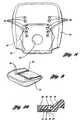
- the vehicle seat assembly 10comprises a leather cover 12 adapted to cover a lower seat assembly 14 and seat back assembly 16.
- the leather cover 12, shown in Figure 1includes porous surfaces 18,20 to facilitate transfer of heat and moisture from a vehicle occupant through a seat ventilation system, as described below.
- the porous surface 20 of the leather trim cover 12, and its attached layers of fabric, foam and polyester webare secured over a heating pad 22, shown in Figure 3.
- the heating pad 22is preferably a porous material to allow transfer of heat and moisture therethrough in the presence of a pressure differential.
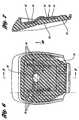
- the heating pad 22is placed on top of a lower foam cushion 24.
- the lower foam cushion 24includes a plurality of air holes 26 formed therethrough from the top surface 28 to the bottom surface 30 thereof, as shown in Figures 3 and 10.
- the lower foam cushion 24is secured atop a seat pan assembly 32, which is preferably a steel component, and a spring net 34 is supported by a plurality of springs 36 across the pan assembly 32 for supporting the lower foam cushion 24.
- a fan assembly 38is secured to the fan opening 40 on the pan assembly 32 for creating a vacuum within the air holes 26 for drawing heat and moisture from the porous surface 20 of the other trim cover 12.
- a bottom flow channel 42is formed along the bottom surface 30 of the lower foam cushion 24 in fluid communication with the plurality of air holes 26 for directing air flow toward the impeller in the fan assembly 38.
- the bottom flow channel 42comprises a porous cushion member 44 through which air flows while the porous cushion member 44 cushions the vehicle occupant.
- the porous cushion member 44could be a rubber hair material such as that available from Fehrer Corporation of Kitzingen-Main, Germany, or other open cell material which provides cushioning support while allowing air to flow therethrough.
- the lower surface 46is covered with a thin polyurethane sheet 48 for preventing escape of air flow from the porous cushion member 44 and for directing the air flow to the fan assembly 38.
- the foam cushion 24also includes a large aperture 50 in communication between the bottom flow channel 42 and the fan assembly 38. Also shown in Figure 8 is a rod 50 configured for attachment to the leather cover 12 along its bottom edges by means of hog rings for attaching the cover 12 to the seat assembly. Figures 3, 8 and 10 also show a channel 52 formed in the top surface 28 of the cushion 24 for trim cover attachment.
- the lower seat assembly 14is provided with appropriate structure for creating a vacuum to draw heat and moisture away from the porous surface 20 of the trim cover 12.
- the porous cushion member 44is effective in enabling such air flow between the air holes 26 and the fan assembly 38 while still providing cushioning support to the vehicle occupant.
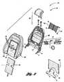
- the porous surface 18 of the trim cover material 12again includes a perforated fabric, a foam layer with open cells, and a polyester web material secured thereto.
- a heating pad 60is attached over the front surface 62 of the seat back foam cushion 64.
- the heating pad 60is preferably a porous material to allow transfer of heat and moisture therethrough.
- the seat back foam cushion 64is positioned against a backrest frame 66, and a spring net 68 and springs 70 are provided for supporting the seat back foam cushion 64 with respect to the backrest frame 66.
- the backrest frame 66includes an aperture 72 formed therethrough for cooperation with the impeller assembly 74. Accordingly, the impeller assembly 74 may communicate with the aperture 76 formed in the seat back foam cushion 64 for creating a vacuum, and thus a pressure differential is established across the porous surface 18 of the trim cover 12 for drawing heat and moisture away from the vehicle occupant.
- An air evacuation bracket 78 and cardboard plate 80are positioned over the back of the impeller assembly 74 for directing drawn air downward toward the bottom of the seat assembly.
- the seat back assembly 16also includes a headrest assembly 82.
- the seat back foam cushion 64includes front and rear surfaces 84,86, respectively.
- a plurality of air channels 76extend from the front surface 84 to the rear surface 86 of the seat back foam cushion 64.
- a rear flow channel 88is formed along the rear surface 86 in fluid communication with the plurality of air channels 76 for directing air flow toward the impeller assembly 74 through the bellows 90.
- the rear flow channel 88comprises a porous cushion member 92, such as a rubber hair material, or open cell material, for allowing air to flow therethrough while cushioning the vehicle occupant.
- the back surface 94is covered with a polyurethane sheet 96 for preventing escape of air from the porous cushion member 92 and for directing air to the bellows 90.
- the front surface 84 of the seat back foam cushion 64also includes a channel 98 formed therein, as shown in Figures 2 and 5, for trim cover attachment.
- the impeller assembly 74may be used for creating a vacuum within the seat back foam cushion 64 for drawing heat and moisture away from the porous surface 18 of the trim cover material 12 for improving occupant comfort.
- the porous cushion member 92allows such movement of air within the seat back foam cushion 64 while providing cushioning support for the vehicle occupant.
Landscapes
- Engineering & Computer Science (AREA)
- Aviation & Aerospace Engineering (AREA)
- Transportation (AREA)
- Mechanical Engineering (AREA)
- Chair Legs, Seat Parts, And Backrests (AREA)
- Seats For Vehicles (AREA)
Description
Claims (7)
- A vehicle seat assembly (10), comprising:characterised in that said rear flow channel(88,42) comprises a porous cushion member (92,44)substantially filling the rear flow channel (88,42)through which air flows while the porous cushionmember (92,44) cushions the vehicle occupant.a seat foam cushion (64,24) having front (84,28)and rear (86,30) surfaces, said seat foam cushion(64,24) having a plurality of air channels (76,26)formed therethrough from the front (84,28) to rear(86,30) surface,a porous trim cover material (12) positionedadjacent the front surface (84,28) of the seat foamcushion (64,24);a first impeller (74,38) positioned in fluidcommunication with said plurality of air channels(76,26) for creating a pressure differential formoving heat and moisture away from said trim covermaterial (12); anda rear flow channel (88,42) formed along saidrear surface (86,30) in fluid communication with saidplurality of air channels (76,26) for directing airflow toward the first impeller (74,38),
- The vehicle seat assembly (10) of claim 1, whereinsaid porous cushion member (92,44) comprises a rubberhair material.
- The vehicle seat assembly (10) of claim 1 or 2,wherein said rear flow channel (88,42) further comprises a thin, air-impermeable layer (96,48)positioned against the porous cushion member (92,44).
- The vehicle seat assembly (10) of any preceding claimin which the seat assembly (10) comprises a seat back(16) and the seat foam cushion comprises seat backfoam cushion (64) and part of the seat back (16).
- The vehicle seat assembly (10) of claim 4, furthercomprising:a lower seat (14) including a lower foam cushion(24) therein having top (28) and bottom (30) surfaces,said lower foam cushion (24) having a plurality of airholes (26) formed therethrough from the top (28) tothe bottom (30) surface;said porous trim cover (12) further extendingfrom the seat back foam cushion (64) across the topsurface (28) of the lower foam cushion (24);a second impeller (38) positioned in fluidcommunication with said plurality of air holes (26)for creating a pressure differential for drawing heatand moisture away from said trim cover material (12).
- The vehicle seat assembly (10) of claim 5, furthercomprising a bottom flow channel (42) formed alongsaid bottom surface (30) in fluid communication withsaid plurality of air holes (26) for directing airflow toward the second impeller (38), wherein saidbottom flow channel (42) comprises a further porouscushion member (44) substantially filling the bottomflow channel (42) through which air flows while theporous cushion member (44) cushions the vehicleoccupant.
- The vehicle seat assembly (10) of any one of claims 1to 3 in which the seat assembly (10) comprises a lowerseat (14) and the seat foam cushion comprises lowerfoam cushion (24) and part of the lower seat (14).
Applications Claiming Priority (3)
| Application Number | Priority Date | Filing Date | Title |
|---|---|---|---|
| US08/919,077US5927817A (en) | 1997-08-27 | 1997-08-27 | Ventilated vehicle seat assembly |
| US919077 | 1997-08-27 | ||
| PCT/US1998/016173WO1999010198A1 (en) | 1997-08-27 | 1998-08-03 | Ventilated vehicle seat assembly |
Publications (2)
| Publication Number | Publication Date |
|---|---|
| EP1007386A2 EP1007386A2 (en) | 2000-06-14 |
| EP1007386B1true EP1007386B1 (en) | 2004-05-06 |
Family
ID=25441466
Family Applications (1)
| Application Number | Title | Priority Date | Filing Date |
|---|---|---|---|
| EP98938313AExpired - LifetimeEP1007386B1 (en) | 1997-08-27 | 1998-08-03 | Ventilated vehicle seat assembly |
Country Status (6)
| Country | Link |
|---|---|
| US (1) | US5927817A (en) |
| EP (1) | EP1007386B1 (en) |
| JP (1) | JP2001514028A (en) |
| AU (1) | AU8686398A (en) |
| DE (1) | DE69823674T2 (en) |
| WO (1) | WO1999010198A1 (en) |
Families Citing this family (122)
| Publication number | Priority date | Publication date | Assignee | Title |
|---|---|---|---|---|
| DE19745521C2 (en)* | 1997-10-15 | 2001-12-13 | Daimler Chrysler Ag | Upholstery for a vehicle seat |
| JPH11137371A (en)* | 1997-11-10 | 1999-05-25 | Aisin Seiki Co Ltd | Ventilation sheet device |
| DE19804100C1 (en)* | 1998-02-03 | 1999-05-12 | Daimler Chrysler Ag | Automobile seat with incorporated ventilation |
| US6119463A (en) | 1998-05-12 | 2000-09-19 | Amerigon | Thermoelectric heat exchanger |
| DE19851209C1 (en)* | 1998-12-09 | 2000-04-13 | Daimler Chrysler Ag | Back rest for motor vehicle seat has lordosis support with fan blower connected by duct to porous ventilation cover layer |
| EP1086852B1 (en)* | 1999-09-21 | 2004-01-28 | Johnson Controls GmbH | Seat cushion for vehicle seats |
| US6106057A (en)* | 1999-09-22 | 2000-08-22 | Lee; Shih-Ping | Ventilation baby seat |
| DE19954978C1 (en)* | 1999-11-16 | 2001-01-11 | Daimler Chrysler Ag | Seat squab for automobile passenger seat has perforated electric heating mat between actively ventilated cushion pad and pervious seat cushion covering |
| SE0000679L (en) | 2000-03-02 | 2001-03-12 | Lear Corp | Vehicle seat and procedure for its comfort ventilation |
| US7668362B2 (en)* | 2000-05-03 | 2010-02-23 | Aperio Technologies, Inc. | System and method for assessing virtual slide image quality |
| WO2002011968A2 (en)* | 2000-08-04 | 2002-02-14 | Woodbridge Foam Corporation | Foam element having molded gas passageways and process for production thereof |
| DE10047754C5 (en)* | 2000-09-27 | 2010-04-22 | Daimler Ag | Wind protection device for an open motor vehicle |
| DE10054010C1 (en)* | 2000-11-01 | 2002-01-03 | Daimler Chrysler Ag | Vehicle seat for open car; has air supply unit with fan and nozzles arranged in upper part of back rest to reduce undesired draughts, where height of fan can be adjusted with respect to back rest |
| DE10054008B4 (en)* | 2000-11-01 | 2004-07-08 | Daimlerchrysler Ag | Automobile seat |
| US6786541B2 (en) | 2001-01-05 | 2004-09-07 | Johnson Controls Technology Company | Air distribution system for ventilated seat |
| US7040710B2 (en)* | 2001-01-05 | 2006-05-09 | Johnson Controls Technology Company | Ventilated seat |
| US6629724B2 (en) | 2001-01-05 | 2003-10-07 | Johnson Controls Technology Company | Ventilated seat |
| DE10128415A1 (en)* | 2001-06-12 | 2002-12-19 | Daimler Chrysler Ag | Vehicle seat with seat ventilation |
| DE20112473U1 (en) | 2001-07-28 | 2002-12-19 | Johnson Controls GmbH, 51399 Burscheid | Air-conditioned upholstery part for a vehicle seat |
| US6696948B2 (en)* | 2001-11-02 | 2004-02-24 | Elesys North America, Inc. | Wet seat protection for air bag control occupant detection |
| DE20120516U1 (en)* | 2001-12-19 | 2003-04-30 | Johnson Controls GmbH, 51399 Burscheid | Ventilation system for an upholstered part |
| USD469998S1 (en) | 2002-01-02 | 2003-02-11 | Myles P. Feeney | Combination head bed and heat seat |
| DE10207489B4 (en)* | 2002-02-22 | 2005-06-09 | Daimlerchrysler Ag | Automotive seat |
| US6893086B2 (en)* | 2002-07-03 | 2005-05-17 | W.E.T. Automotive Systems Ltd. | Automotive vehicle seat insert |
| US6857697B2 (en) | 2002-08-29 | 2005-02-22 | W.E.T. Automotive Systems Ag | Automotive vehicle seating comfort system |
| JP2004161137A (en)* | 2002-11-13 | 2004-06-10 | Denso Corp | Vehicular seat air conditioner |
| DE10259648B4 (en) | 2002-12-18 | 2006-01-26 | W.E.T. Automotive Systems Ag | Air-conditioned seat and air conditioning device for a ventilated seat |
| DE10259621B4 (en) | 2002-12-18 | 2005-12-01 | W.E.T. Automotive Systems Ag | Vehicle seat and associated air conditioning device |
| DE10316275B4 (en) | 2003-04-08 | 2009-06-18 | Johnson Controls Gmbh | vehicle seat |
| US7168758B2 (en)* | 2003-06-05 | 2007-01-30 | Igb Automotive Ltd. | Modular comfort assembly for occupant support |
| US7356912B2 (en) | 2003-09-25 | 2008-04-15 | W.E.T. Automotive Systems, Ltd. | Method for ventilating a seat |
| US7274007B2 (en) | 2003-09-25 | 2007-09-25 | W.E.T. Automotive Systems Ltd. | Control system for operating automotive vehicle components |
| US7425034B2 (en) | 2003-10-17 | 2008-09-16 | W.E.T. Automotive Systems Ag | Automotive vehicle seat having a comfort system |
| US7370911B2 (en) | 2003-10-17 | 2008-05-13 | W.E.T. Automotive Systems, Ag | Automotive vehicle seat insert |
| US7461892B2 (en) | 2003-12-01 | 2008-12-09 | W.E.T. Automotive Systems, A.C. | Valve layer for a seat |
| US20050200166A1 (en)* | 2004-03-09 | 2005-09-15 | Ki-Yeong Noh | Vehicle seat with cooling/heating device |
| DE202004005116U1 (en)* | 2004-03-31 | 2005-08-18 | Lear Corporation, Southfield | Vehicle seat with a ventilation system |
| US7114771B2 (en)* | 2004-05-25 | 2006-10-03 | Amerigon, Inc. | Climate controlled seat |
| US20060087160A1 (en)* | 2004-10-25 | 2006-04-27 | Hanh Dong | Apparatus for providing fluid through a vehicle seat |
| US20070262621A1 (en)* | 2004-10-25 | 2007-11-15 | Hanh Dong | Apparatus for providing fluid through a vehicle seat |
| US7452028B2 (en)* | 2004-12-03 | 2008-11-18 | Igb Automotive Ltd. | Modular comfort assembly for occupant support |
| DE102004060460A1 (en)* | 2004-12-16 | 2006-07-06 | Daimlerchrysler Ag | Backrest for a motor vehicle seat with an air supply device |
| US7587901B2 (en) | 2004-12-20 | 2009-09-15 | Amerigon Incorporated | Control system for thermal module in vehicle |
| US7320223B1 (en) | 2005-01-28 | 2008-01-22 | United States Of America As Represented By The Administrator Of The National Aeronautics And Space Administration | System for controlling child safety seat environment |
| KR100909033B1 (en)* | 2005-02-07 | 2009-07-22 | 엘앤드피 프라퍼티 매니지먼트 캄파니 | Heating, Cooling, and Ventilation Systems for Automotive Applications |
| US20060214480A1 (en)* | 2005-03-23 | 2006-09-28 | John Terech | Vehicle seat with thermal elements |
| US7827805B2 (en) | 2005-03-23 | 2010-11-09 | Amerigon Incorporated | Seat climate control system |
| DE102005018445B3 (en) | 2005-04-20 | 2006-06-29 | W.E.T. Automotive Systems Ag | Air conditioning device for e.g. vehicle seat has air-conditioning zones, which are connected to recess by connecting device whereby recess allows the air to pass through it partially in transverse direction inspite of cover |
| WO2006124835A1 (en)* | 2005-05-16 | 2006-11-23 | Amerigon, Inc. | Ventilated headrest |
| US7478869B2 (en) | 2005-08-19 | 2009-01-20 | W.E.T. Automotive Systems, Ag | Automotive vehicle seat insert |
| ATE547285T1 (en) | 2006-01-30 | 2012-03-15 | Amerigon Inc | COOLING SYSTEM FOR A CONTAINER IN A VEHICLE |
| US7591507B2 (en) | 2006-04-13 | 2009-09-22 | Amerigon Incorporated | Tie strap for climate controlled seat |
| DE102006031899B3 (en)* | 2006-04-20 | 2007-06-21 | W.E.T. Automotive Systems Ag | Interior component e.g. seat, surface air conditioning system for motor vehicle, has coating layer that is connected with air conditioning layer such that insertion case is formed, and detector device that is inserted into case |
| US8539624B2 (en) | 2006-05-31 | 2013-09-24 | Gentherm Incorporated | Structure based fluid distribution system |
| US8222511B2 (en)* | 2006-08-03 | 2012-07-17 | Gentherm | Thermoelectric device |
| US7708338B2 (en)* | 2006-10-10 | 2010-05-04 | Amerigon Incorporated | Ventilation system for seat |
| US20080087316A1 (en) | 2006-10-12 | 2008-04-17 | Masa Inaba | Thermoelectric device with internal sensor |
| EP2567637B1 (en) | 2006-10-13 | 2014-08-06 | Gentherm Incorporated | Air conditioning bed |
| KR100778593B1 (en)* | 2006-10-25 | 2007-11-22 | 현대자동차주식회사 | Thermoelectric element mounting structure of car air conditioning heating sheet |
| WO2008057962A2 (en)* | 2006-11-01 | 2008-05-15 | Amerigon Incorporated | Chair with air conditioning device |
| US7640754B2 (en) | 2006-12-14 | 2010-01-05 | Amerigon Incorporated | Insert duct piece for thermal electric module |
| JP5485701B2 (en) | 2007-01-10 | 2014-05-07 | ジェンサーム インコーポレイティド | Thermoelectric element |
| WO2008115831A1 (en) | 2007-03-16 | 2008-09-25 | Amerigon Incorporated | Air warmer |
| US20090033130A1 (en)* | 2007-07-02 | 2009-02-05 | David Marquette | Fluid delivery systems for climate controlled seats |
| US9105809B2 (en) | 2007-07-23 | 2015-08-11 | Gentherm Incorporated | Segmented thermoelectric device |
| CN101808839B (en)* | 2007-07-23 | 2012-09-19 | 阿美里根公司 | Radiant Thermoelectric Device Components |
| WO2009036077A1 (en) | 2007-09-10 | 2009-03-19 | Amerigon, Inc. | Operational control schemes for ventilated seat or bed assemblies |
| US7637564B1 (en)* | 2007-10-09 | 2009-12-29 | Schroeder Zachary D | Vacuum system for a highchair |
| JP2009090016A (en)* | 2007-10-11 | 2009-04-30 | T S Tec Kk | Seat, seat cushion and backrest thereof |
| US9125497B2 (en) | 2007-10-15 | 2015-09-08 | Gentherm Incorporated | Climate controlled bed assembly with intermediate layer |
| US8181290B2 (en) | 2008-07-18 | 2012-05-22 | Amerigon Incorporated | Climate controlled bed assembly |
| CN101795893A (en)* | 2007-10-29 | 2010-08-04 | W.E.T.汽车系统股份公司 | The air conditioning equipment that is used for seat |
| WO2009076123A2 (en) | 2007-12-10 | 2009-06-18 | W.E.T. Automotive Systems Ag | Improved seat conditioning module and method |
| CN114715003A (en) | 2008-02-01 | 2022-07-08 | 金瑟姆股份公司 | Condensation and humidity sensor for thermoelectric devices |
| US20090218855A1 (en)* | 2008-02-26 | 2009-09-03 | Amerigon Incorporated | Climate control systems and devices for a seating assembly |
| DE102008017965B4 (en) | 2008-04-08 | 2011-06-01 | W.E.T. Automotive Systems Ag | aerator |
| DE202009017050U1 (en) | 2008-12-21 | 2010-05-12 | W.E.T. Automotive Systems Ag | aerator |
| WO2010088405A1 (en) | 2009-01-28 | 2010-08-05 | Amerigon Incorporated | Convective heater |
| DE202010002050U1 (en)* | 2009-02-18 | 2010-07-15 | W.E.T. Automotive Systems Ag | Air conditioning device for vehicle seats |
| US8893329B2 (en) | 2009-05-06 | 2014-11-25 | Gentherm Incorporated | Control schemes and features for climate-controlled beds |
| US8332975B2 (en) | 2009-08-31 | 2012-12-18 | Gentherm Incorporated | Climate-controlled topper member for medical beds |
| IT1397239B1 (en) | 2009-12-01 | 2013-01-04 | Zecca | SYSTEM TO WELCOME A USER SEATED OR GRADED. |
| DE102011014516A1 (en) | 2010-04-06 | 2012-05-10 | W.E.T. Automotive Systems Ag | MFP |
| US9121414B2 (en) | 2010-11-05 | 2015-09-01 | Gentherm Incorporated | Low-profile blowers and methods |
| JP5673380B2 (en)* | 2011-06-21 | 2015-02-18 | トヨタ紡織株式会社 | Vehicle seat |
| DE102012014678A1 (en) | 2011-08-19 | 2013-02-21 | W.E.T. Automotive Systems Ag | heater |
| WO2013052823A1 (en) | 2011-10-07 | 2013-04-11 | Gentherm Incorporated | Thermoelectric device controls and methods |
| DE202011110107U1 (en) | 2011-11-17 | 2013-02-19 | W.E.T. Automotive Systems Ag | Tempering device |
| DE102012020516A1 (en) | 2011-12-09 | 2013-06-13 | W.E.T. Automotive Systems Ag | Temperature control device for an electrochemical voltage source |
| DE102011121980A1 (en) | 2011-12-26 | 2013-06-27 | W.E.T. Automotive Systems Ag | Air conveyor |
| US9989267B2 (en) | 2012-02-10 | 2018-06-05 | Gentherm Incorporated | Moisture abatement in heating operation of climate controlled systems |
| JP5811944B2 (en)* | 2012-05-09 | 2015-11-11 | トヨタ紡織株式会社 | Vehicle seat |
| JP2015524997A (en) | 2012-07-06 | 2015-08-27 | ジェンサーム インコーポレイテッドGentherm Incorporated | System and method for cooling an inductive charging assembly |
| DE202012011717U1 (en) | 2012-07-25 | 2013-10-28 | W.E.T. Automotive Systems Ag | Nackenwärmer |
| US9662962B2 (en) | 2013-11-05 | 2017-05-30 | Gentherm Incorporated | Vehicle headliner assembly for zonal comfort |
| CN105813505B (en) | 2013-12-05 | 2019-07-09 | 金瑟姆股份公司 | Systems and methods for climate-controlled seats |
| CN104742772B (en) | 2013-12-26 | 2017-10-20 | 捷温汽车系统(中国)有限公司 | Particularly for the air-heater of the neck heater in transport facility seat |
| WO2015123585A1 (en) | 2014-02-14 | 2015-08-20 | Gentherm Incorporated | Conductive convective climate controlled seat |
| WO2015156218A1 (en)* | 2014-04-11 | 2015-10-15 | テイ・エス テック株式会社 | Vehicle seat |
| JP5989706B2 (en)* | 2014-04-25 | 2016-09-07 | トヨタ紡織株式会社 | Vehicle seat |
| US10160356B2 (en) | 2014-05-09 | 2018-12-25 | Gentherm Incorporated | Climate control assembly |
| US11639816B2 (en) | 2014-11-14 | 2023-05-02 | Gentherm Incorporated | Heating and cooling technologies including temperature regulating pad wrap and technologies with liquid system |
| WO2016077843A1 (en) | 2014-11-14 | 2016-05-19 | Cauchy Charles J | Heating and cooling technologies |
| US11857004B2 (en) | 2014-11-14 | 2024-01-02 | Gentherm Incorporated | Heating and cooling technologies |
| DE102016009884A1 (en) | 2015-12-14 | 2017-06-14 | Gentherm Gmbh | Neck blower for a vehicle seat and rule-method for it |
| WO2017137023A1 (en) | 2016-02-10 | 2017-08-17 | Gentherm Gmbh | Device for controlling the temperature of the neck region of a user of a vehicle seat |
| CN109562705A (en)* | 2016-08-05 | 2019-04-02 | 提爱思科技股份有限公司 | Vehicle seat |
| JP6756240B2 (en)* | 2016-11-08 | 2020-09-16 | トヨタ紡織株式会社 | Vehicle seat blower and vehicle seat |
| JP6743684B2 (en)* | 2016-12-22 | 2020-08-19 | トヨタ紡織株式会社 | Vehicle seat blower and vehicle seat |
| JP6482587B2 (en) | 2017-03-24 | 2019-03-13 | テイ・エス テック株式会社 | Vehicle seat |
| JP6309130B1 (en)* | 2017-03-24 | 2018-04-11 | テイ・エス テック株式会社 | Vehicle seat |
| JP6583325B2 (en) | 2017-03-24 | 2019-10-02 | テイ・エス テック株式会社 | Vehicle seat |
| US11396249B2 (en)* | 2017-05-31 | 2022-07-26 | Kurabe Industrial Co., Ltd. | Ventilation mat |
| US10821803B2 (en) | 2017-08-29 | 2020-11-03 | Ford Global Technologies, Llc | Vehicle seat with cooling fluidflow |
| US10252652B2 (en)* | 2017-08-29 | 2019-04-09 | Ford Global Technologies, Llc | Seating assembly with heating and cooling |
| US10507745B2 (en) | 2017-08-29 | 2019-12-17 | Ford Global Technologies, Llc | Seating assembly with thermoelectric devices |
| US10245983B1 (en) | 2017-09-21 | 2019-04-02 | Ford Global Technologies Llc | Off-road performance seat |
| US10518675B2 (en)* | 2017-11-13 | 2019-12-31 | Gulfstream Aerospace Corporation | Seat assembly including a modular foam arrangement with a venting modular section and method for fabricating the same |
| US11223004B2 (en) | 2018-07-30 | 2022-01-11 | Gentherm Incorporated | Thermoelectric device having a polymeric coating |
| JP7035947B2 (en)* | 2018-10-09 | 2022-03-15 | 株式会社デンソー | Seat heater device |
| CN113167510B (en) | 2018-11-30 | 2025-10-03 | 金瑟姆股份公司 | Thermoelectric regulation system and method |
| US11152557B2 (en) | 2019-02-20 | 2021-10-19 | Gentherm Incorporated | Thermoelectric module with integrated printed circuit board |
Family Cites Families (23)
| Publication number | Priority date | Publication date | Assignee | Title |
|---|---|---|---|---|
| GB957135A (en)* | 1962-07-07 | 1964-05-06 | Arthur Paul Pedrick | Suction apparatus for retaining personnel in vehicles or aircraft in their seats |
| US3137523A (en)* | 1963-09-20 | 1964-06-16 | Karner Frank | Air conditioned seat |
| FR94417E (en)* | 1968-04-05 | 1969-08-14 | Ducrocq Louis Francois | Air-conditioned cushion. |
| US3895841A (en)* | 1974-09-03 | 1975-07-22 | Herbert A Lebert | Vacuum actuated vehicle safety device |
| DE3609095A1 (en)* | 1985-03-28 | 1986-10-09 | Keiper Recaro GmbH & Co KG, 5630 Remscheid | Vehicle seat |
| EP0206152B1 (en)* | 1985-06-24 | 1991-01-30 | Adriano Antolini | Perfected cover, particularly for vehicle seats |
| DE3607041A1 (en)* | 1986-01-31 | 1987-08-06 | Metzeler Schaum Gmbh | BACK PAD FOR A PASSENGER SEAT |
| DE3725146A1 (en)* | 1987-07-29 | 1989-02-09 | Bayerische Motoren Werke Ag | Seat, in particular for motor vehicles |
| SE459389B (en)* | 1987-08-17 | 1989-07-03 | Christer Tennstedt | BODY SUPPORT DEVICE FOR THE SEAT AND / OR THE SEAT WITH A CHAIR |
| US5403065A (en)* | 1990-06-19 | 1995-04-04 | F.I.M.A.C. Fabbrica Italiana Macchine Aria Compressa Spa | Bioconditioning device for objects with surfaces susceptible of making contact with body parts |
| US5102189A (en)* | 1990-12-28 | 1992-04-07 | Tachi-S Co., Ltd. | Ventilated seat |
| JPH0523235A (en)* | 1991-07-19 | 1993-02-02 | Japan Gore Tex Inc | Seat seat |
| FR2686299A1 (en)* | 1992-01-17 | 1993-07-23 | Depecker Lucienne | Aeraulic device for improving the hydrothermic comfort of vehicle seats |
| US5356205A (en)* | 1992-09-18 | 1994-10-18 | Inmotion, Inc. | Seat assembly with a defined flexure region, venting or support nodules |
| DE4308119C2 (en)* | 1993-03-15 | 1996-07-11 | Karl Prof Dr Frey | Method and device for influencing the climate for occupants of a motor vehicle |
| US5626021A (en)* | 1993-11-22 | 1997-05-06 | Amerigon, Inc. | Variable temperature seat climate control system |
| US5597200A (en)* | 1993-11-22 | 1997-01-28 | Amerigon, Inc. | Variable temperature seat |
| US5626387A (en)* | 1995-02-27 | 1997-05-06 | Yeh; Ching-Hsiu | Cushion with cooling stubs |
| SE504973C2 (en)* | 1995-09-14 | 1997-06-02 | Walinov Ab | Fan unit included in a ventilated vehicle seat |
| SE504942C2 (en)* | 1995-09-14 | 1997-06-02 | Walinov Ab | Device for ventilating a vehicle seat |
| US5613729A (en)* | 1996-01-22 | 1997-03-25 | Summer, Jr.; Charlie B. | Ventilated seat cover apparatus |
| FR2744896A3 (en)* | 1996-02-15 | 1997-08-22 | Ling Chih Lung | Motor vehicle seat cushion air conditioned by fan |
| US5626386A (en)* | 1996-07-16 | 1997-05-06 | Atoma International, Inc. | Air cooled/heated vehicle seat assembly |
- 1997
- 1997-08-27USUS08/919,077patent/US5927817A/ennot_activeExpired - Lifetime
- 1998
- 1998-08-03AUAU86863/98Apatent/AU8686398A/ennot_activeAbandoned
- 1998-08-03WOPCT/US1998/016173patent/WO1999010198A1/enactiveIP Right Grant
- 1998-08-03JPJP2000507550Apatent/JP2001514028A/enactivePending
- 1998-08-03EPEP98938313Apatent/EP1007386B1/ennot_activeExpired - Lifetime
- 1998-08-03DEDE69823674Tpatent/DE69823674T2/ennot_activeExpired - Lifetime
Also Published As
| Publication number | Publication date |
|---|---|
| EP1007386A2 (en) | 2000-06-14 |
| US5927817A (en) | 1999-07-27 |
| AU8686398A (en) | 1999-03-16 |
| DE69823674T2 (en) | 2004-10-07 |
| JP2001514028A (en) | 2001-09-11 |
| DE69823674D1 (en) | 2004-06-09 |
| WO1999010198A8 (en) | 1999-05-06 |
| WO1999010198A1 (en) | 1999-03-04 |
Similar Documents
| Publication | Publication Date | Title |
|---|---|---|
| EP1007386B1 (en) | Ventilated vehicle seat assembly | |
| US6511125B1 (en) | Ventilated seat pad | |
| US6619737B2 (en) | Seat module for a vehicle seat which can be actively ventilated | |
| US6019420A (en) | Vehicle seat | |
| JP3395143B2 (en) | Backrest for vehicle seat | |
| US6808230B2 (en) | Seat module for a vehicle seat which can be actively ventilated and method of making same | |
| EP1349746B1 (en) | Ventilated seat for a vehicle | |
| JP4121500B2 (en) | Automotive seat cushion | |
| US6062641A (en) | Seat apparatus with air flow | |
| JP3835329B2 (en) | Vehicle seat air conditioner | |
| US6189966B1 (en) | Vehicle seat | |
| US6196627B1 (en) | Vehicle seat | |
| US6224150B1 (en) | Cushioning for the seat part and/or the backrest of a vehicle seat | |
| US6206465B1 (en) | Cushioning for a vehicle seat | |
| US7533941B2 (en) | Seat pad for vehicle | |
| US6247751B1 (en) | Seat, especially a vehicle seat | |
| JP2000333782A (en) | Seat for vehicle | |
| US7328944B2 (en) | Contour motorcycle seat | |
| JP4179497B2 (en) | seat | |
| US20240239253A1 (en) | Ventilated seat | |
| US12296733B2 (en) | Climate controlled seat | |
| KR19990039429U (en) | Car seat cover |
Legal Events
| Date | Code | Title | Description |
|---|---|---|---|
| PUAI | Public reference made under article 153(3) epc to a published international application that has entered the european phase | Free format text:ORIGINAL CODE: 0009012 | |
| 17P | Request for examination filed | Effective date:20000214 | |
| AK | Designated contracting states | Kind code of ref document:A2 Designated state(s):DE GB IT SE | |
| 17Q | First examination report despatched | Effective date:20030221 | |
| GRAP | Despatch of communication of intention to grant a patent | Free format text:ORIGINAL CODE: EPIDOSNIGR1 | |
| GRAS | Grant fee paid | Free format text:ORIGINAL CODE: EPIDOSNIGR3 | |
| GRAA | (expected) grant | Free format text:ORIGINAL CODE: 0009210 | |
| AK | Designated contracting states | Kind code of ref document:B1 Designated state(s):DE GB IT SE | |
| PG25 | Lapsed in a contracting state [announced via postgrant information from national office to epo] | Ref country code:IT Free format text:LAPSE BECAUSE OF FAILURE TO SUBMIT A TRANSLATION OF THE DESCRIPTION OR TO PAY THE FEE WITHIN THE PRESCRIBED TIME-LIMIT;WARNING: LAPSES OF ITALIAN PATENTS WITH EFFECTIVE DATE BEFORE 2007 MAY HAVE OCCURRED AT ANY TIME BEFORE 2007. THE CORRECT EFFECTIVE DATE MAY BE DIFFERENT FROM THE ONE RECORDED. Effective date:20040506 | |
| REG | Reference to a national code | Ref country code:GB Ref legal event code:FG4D | |
| REF | Corresponds to: | Ref document number:69823674 Country of ref document:DE Date of ref document:20040609 Kind code of ref document:P | |
| PG25 | Lapsed in a contracting state [announced via postgrant information from national office to epo] | Ref country code:SE Free format text:LAPSE BECAUSE OF FAILURE TO SUBMIT A TRANSLATION OF THE DESCRIPTION OR TO PAY THE FEE WITHIN THE PRESCRIBED TIME-LIMIT Effective date:20040806 | |
| PLBE | No opposition filed within time limit | Free format text:ORIGINAL CODE: 0009261 | |
| STAA | Information on the status of an ep patent application or granted ep patent | Free format text:STATUS: NO OPPOSITION FILED WITHIN TIME LIMIT | |
| 26N | No opposition filed | Effective date:20050208 | |
| PGFP | Annual fee paid to national office [announced via postgrant information from national office to epo] | Ref country code:GB Payment date:20150827 Year of fee payment:18 Ref country code:DE Payment date:20150827 Year of fee payment:18 | |
| REG | Reference to a national code | Ref country code:DE Ref legal event code:R119 Ref document number:69823674 Country of ref document:DE | |
| GBPC | Gb: european patent ceased through non-payment of renewal fee | Effective date:20160803 | |
| PG25 | Lapsed in a contracting state [announced via postgrant information from national office to epo] | Ref country code:DE Free format text:LAPSE BECAUSE OF NON-PAYMENT OF DUE FEES Effective date:20170301 Ref country code:GB Free format text:LAPSE BECAUSE OF NON-PAYMENT OF DUE FEES Effective date:20160803 |