EP1006913B2 - Anterior cervical plating system - Google Patents
Anterior cervical plating systemDownload PDFInfo
- Publication number
- EP1006913B2 EP1006913B2EP98904937AEP98904937AEP1006913B2EP 1006913 B2EP1006913 B2EP 1006913B2EP 98904937 AEP98904937 AEP 98904937AEP 98904937 AEP98904937 AEP 98904937AEP 1006913 B2EP1006913 B2EP 1006913B2
- Authority
- EP
- European Patent Office
- Prior art keywords
- plate
- bone screw
- bone
- cervical
- locking element
- Prior art date
- Legal status (The legal status is an assumption and is not a legal conclusion. Google has not performed a legal analysis and makes no representation as to the accuracy of the status listed.)
- Expired - Lifetime
Links
Images


Classifications
- A—HUMAN NECESSITIES
- A61—MEDICAL OR VETERINARY SCIENCE; HYGIENE
- A61B—DIAGNOSIS; SURGERY; IDENTIFICATION
- A61B17/00—Surgical instruments, devices or methods
- A61B17/16—Instruments for performing osteoclasis; Drills or chisels for bones; Trepans
- A61B17/1604—Chisels; Rongeurs; Punches; Stamps
- A—HUMAN NECESSITIES
- A61—MEDICAL OR VETERINARY SCIENCE; HYGIENE
- A61B—DIAGNOSIS; SURGERY; IDENTIFICATION
- A61B17/00—Surgical instruments, devices or methods
- A61B17/56—Surgical instruments or methods for treatment of bones or joints; Devices specially adapted therefor
- A61B17/58—Surgical instruments or methods for treatment of bones or joints; Devices specially adapted therefor for osteosynthesis, e.g. bone plates, screws or setting implements
- A61B17/68—Internal fixation devices, including fasteners and spinal fixators, even if a part thereof projects from the skin
- A61B17/70—Spinal positioners or stabilisers, e.g. stabilisers comprising fluid filler in an implant
- A61B17/7058—Plates mounted on top of bone anchor heads or shoulders
- A—HUMAN NECESSITIES
- A61—MEDICAL OR VETERINARY SCIENCE; HYGIENE
- A61B—DIAGNOSIS; SURGERY; IDENTIFICATION
- A61B17/00—Surgical instruments, devices or methods
- A61B17/16—Instruments for performing osteoclasis; Drills or chisels for bones; Trepans
- A61B17/17—Guides or aligning means for drills, mills, pins or wires
- A61B17/1739—Guides or aligning means for drills, mills, pins or wires specially adapted for particular parts of the body
- A61B17/1757—Guides or aligning means for drills, mills, pins or wires specially adapted for particular parts of the body for the spine
- A—HUMAN NECESSITIES
- A61—MEDICAL OR VETERINARY SCIENCE; HYGIENE
- A61B—DIAGNOSIS; SURGERY; IDENTIFICATION
- A61B17/00—Surgical instruments, devices or methods
- A61B17/56—Surgical instruments or methods for treatment of bones or joints; Devices specially adapted therefor
- A61B17/58—Surgical instruments or methods for treatment of bones or joints; Devices specially adapted therefor for osteosynthesis, e.g. bone plates, screws or setting implements
- A61B17/68—Internal fixation devices, including fasteners and spinal fixators, even if a part thereof projects from the skin
- A61B17/70—Spinal positioners or stabilisers, e.g. stabilisers comprising fluid filler in an implant
- A61B17/7059—Cortical plates
- A—HUMAN NECESSITIES
- A61—MEDICAL OR VETERINARY SCIENCE; HYGIENE
- A61B—DIAGNOSIS; SURGERY; IDENTIFICATION
- A61B17/00—Surgical instruments, devices or methods
- A61B17/56—Surgical instruments or methods for treatment of bones or joints; Devices specially adapted therefor
- A61B17/58—Surgical instruments or methods for treatment of bones or joints; Devices specially adapted therefor for osteosynthesis, e.g. bone plates, screws or setting implements
- A61B17/68—Internal fixation devices, including fasteners and spinal fixators, even if a part thereof projects from the skin
- A61B17/80—Cortical plates, i.e. bone plates; Instruments for holding or positioning cortical plates, or for compressing bones attached to cortical plates
- A61B17/8004—Cortical plates, i.e. bone plates; Instruments for holding or positioning cortical plates, or for compressing bones attached to cortical plates with means for distracting or compressing the bone or bones
- A61B17/8019—Cortical plates, i.e. bone plates; Instruments for holding or positioning cortical plates, or for compressing bones attached to cortical plates with means for distracting or compressing the bone or bones where the means are a separate tool rather than being part of the plate
- A—HUMAN NECESSITIES
- A61—MEDICAL OR VETERINARY SCIENCE; HYGIENE
- A61B—DIAGNOSIS; SURGERY; IDENTIFICATION
- A61B17/00—Surgical instruments, devices or methods
- A61B17/56—Surgical instruments or methods for treatment of bones or joints; Devices specially adapted therefor
- A61B17/58—Surgical instruments or methods for treatment of bones or joints; Devices specially adapted therefor for osteosynthesis, e.g. bone plates, screws or setting implements
- A61B17/68—Internal fixation devices, including fasteners and spinal fixators, even if a part thereof projects from the skin
- A61B17/80—Cortical plates, i.e. bone plates; Instruments for holding or positioning cortical plates, or for compressing bones attached to cortical plates
- A61B17/8033—Cortical plates, i.e. bone plates; Instruments for holding or positioning cortical plates, or for compressing bones attached to cortical plates having indirect contact with screw heads, or having contact with screw heads maintained with the aid of additional components, e.g. nuts, wedges or head covers
- A61B17/8042—Cortical plates, i.e. bone plates; Instruments for holding or positioning cortical plates, or for compressing bones attached to cortical plates having indirect contact with screw heads, or having contact with screw heads maintained with the aid of additional components, e.g. nuts, wedges or head covers the additional component being a cover over the screw head
- A—HUMAN NECESSITIES
- A61—MEDICAL OR VETERINARY SCIENCE; HYGIENE
- A61B—DIAGNOSIS; SURGERY; IDENTIFICATION
- A61B17/00—Surgical instruments, devices or methods
- A61B17/56—Surgical instruments or methods for treatment of bones or joints; Devices specially adapted therefor
- A61B17/58—Surgical instruments or methods for treatment of bones or joints; Devices specially adapted therefor for osteosynthesis, e.g. bone plates, screws or setting implements
- A61B17/68—Internal fixation devices, including fasteners and spinal fixators, even if a part thereof projects from the skin
- A61B17/84—Fasteners therefor or fasteners being internal fixation devices
- A61B17/86—Pins or screws or threaded wires; nuts therefor
- A61B17/8625—Shanks, i.e. parts contacting bone tissue
- A61B17/863—Shanks, i.e. parts contacting bone tissue with thread interrupted or changing its form along shank, other than constant taper
- A—HUMAN NECESSITIES
- A61—MEDICAL OR VETERINARY SCIENCE; HYGIENE
- A61B—DIAGNOSIS; SURGERY; IDENTIFICATION
- A61B17/00—Surgical instruments, devices or methods
- A61B17/16—Instruments for performing osteoclasis; Drills or chisels for bones; Trepans
- A61B17/1662—Instruments for performing osteoclasis; Drills or chisels for bones; Trepans for particular parts of the body
- A61B17/1671—Instruments for performing osteoclasis; Drills or chisels for bones; Trepans for particular parts of the body for the spine
- A—HUMAN NECESSITIES
- A61—MEDICAL OR VETERINARY SCIENCE; HYGIENE
- A61B—DIAGNOSIS; SURGERY; IDENTIFICATION
- A61B17/00—Surgical instruments, devices or methods
- A61B17/16—Instruments for performing osteoclasis; Drills or chisels for bones; Trepans
- A61B17/17—Guides or aligning means for drills, mills, pins or wires
- A61B17/1728—Guides or aligning means for drills, mills, pins or wires for holes for bone plates or plate screws
- A—HUMAN NECESSITIES
- A61—MEDICAL OR VETERINARY SCIENCE; HYGIENE
- A61B—DIAGNOSIS; SURGERY; IDENTIFICATION
- A61B17/00—Surgical instruments, devices or methods
- A61B17/56—Surgical instruments or methods for treatment of bones or joints; Devices specially adapted therefor
- A61B17/58—Surgical instruments or methods for treatment of bones or joints; Devices specially adapted therefor for osteosynthesis, e.g. bone plates, screws or setting implements
- A61B17/68—Internal fixation devices, including fasteners and spinal fixators, even if a part thereof projects from the skin
- A61B17/80—Cortical plates, i.e. bone plates; Instruments for holding or positioning cortical plates, or for compressing bones attached to cortical plates
- A61B17/8033—Cortical plates, i.e. bone plates; Instruments for holding or positioning cortical plates, or for compressing bones attached to cortical plates having indirect contact with screw heads, or having contact with screw heads maintained with the aid of additional components, e.g. nuts, wedges or head covers
- A—HUMAN NECESSITIES
- A61—MEDICAL OR VETERINARY SCIENCE; HYGIENE
- A61B—DIAGNOSIS; SURGERY; IDENTIFICATION
- A61B17/00—Surgical instruments, devices or methods
- A61B17/56—Surgical instruments or methods for treatment of bones or joints; Devices specially adapted therefor
- A61B17/58—Surgical instruments or methods for treatment of bones or joints; Devices specially adapted therefor for osteosynthesis, e.g. bone plates, screws or setting implements
- A61B17/68—Internal fixation devices, including fasteners and spinal fixators, even if a part thereof projects from the skin
- A61B17/80—Cortical plates, i.e. bone plates; Instruments for holding or positioning cortical plates, or for compressing bones attached to cortical plates
- A61B17/8085—Cortical plates, i.e. bone plates; Instruments for holding or positioning cortical plates, or for compressing bones attached to cortical plates with pliable or malleable elements or having a mesh-like structure, e.g. small strips
- A—HUMAN NECESSITIES
- A61—MEDICAL OR VETERINARY SCIENCE; HYGIENE
- A61B—DIAGNOSIS; SURGERY; IDENTIFICATION
- A61B17/00—Surgical instruments, devices or methods
- A61B17/56—Surgical instruments or methods for treatment of bones or joints; Devices specially adapted therefor
- A61B17/58—Surgical instruments or methods for treatment of bones or joints; Devices specially adapted therefor for osteosynthesis, e.g. bone plates, screws or setting implements
- A61B17/68—Internal fixation devices, including fasteners and spinal fixators, even if a part thereof projects from the skin
- A61B17/84—Fasteners therefor or fasteners being internal fixation devices
- A61B17/86—Pins or screws or threaded wires; nuts therefor
- A61B17/8605—Heads, i.e. proximal ends projecting from bone
- A61B17/861—Heads, i.e. proximal ends projecting from bone specially shaped for gripping driver
- A—HUMAN NECESSITIES
- A61—MEDICAL OR VETERINARY SCIENCE; HYGIENE
- A61B—DIAGNOSIS; SURGERY; IDENTIFICATION
- A61B17/00—Surgical instruments, devices or methods
- A61B17/56—Surgical instruments or methods for treatment of bones or joints; Devices specially adapted therefor
- A61B17/58—Surgical instruments or methods for treatment of bones or joints; Devices specially adapted therefor for osteosynthesis, e.g. bone plates, screws or setting implements
- A61B17/68—Internal fixation devices, including fasteners and spinal fixators, even if a part thereof projects from the skin
- A61B17/84—Fasteners therefor or fasteners being internal fixation devices
- A61B17/86—Pins or screws or threaded wires; nuts therefor
- A61B17/8625—Shanks, i.e. parts contacting bone tissue
- A—HUMAN NECESSITIES
- A61—MEDICAL OR VETERINARY SCIENCE; HYGIENE
- A61B—DIAGNOSIS; SURGERY; IDENTIFICATION
- A61B17/00—Surgical instruments, devices or methods
- A61B17/56—Surgical instruments or methods for treatment of bones or joints; Devices specially adapted therefor
- A61B17/58—Surgical instruments or methods for treatment of bones or joints; Devices specially adapted therefor for osteosynthesis, e.g. bone plates, screws or setting implements
- A61B17/68—Internal fixation devices, including fasteners and spinal fixators, even if a part thereof projects from the skin
- A61B17/84—Fasteners therefor or fasteners being internal fixation devices
- A61B17/86—Pins or screws or threaded wires; nuts therefor
- A61B17/8695—Washers
- A—HUMAN NECESSITIES
- A61—MEDICAL OR VETERINARY SCIENCE; HYGIENE
- A61B—DIAGNOSIS; SURGERY; IDENTIFICATION
- A61B17/00—Surgical instruments, devices or methods
- A61B17/56—Surgical instruments or methods for treatment of bones or joints; Devices specially adapted therefor
- A61B17/58—Surgical instruments or methods for treatment of bones or joints; Devices specially adapted therefor for osteosynthesis, e.g. bone plates, screws or setting implements
- A61B17/88—Osteosynthesis instruments; Methods or means for implanting or extracting internal or external fixation devices
- A61B17/8875—Screwdrivers, spanners or wrenches
- A—HUMAN NECESSITIES
- A61—MEDICAL OR VETERINARY SCIENCE; HYGIENE
- A61B—DIAGNOSIS; SURGERY; IDENTIFICATION
- A61B17/00—Surgical instruments, devices or methods
- A61B2017/0046—Surgical instruments, devices or methods with a releasable handle; with handle and operating part separable
- A—HUMAN NECESSITIES
- A61—MEDICAL OR VETERINARY SCIENCE; HYGIENE
- A61B—DIAGNOSIS; SURGERY; IDENTIFICATION
- A61B17/00—Surgical instruments, devices or methods
- A61B17/56—Surgical instruments or methods for treatment of bones or joints; Devices specially adapted therefor
- A61B17/58—Surgical instruments or methods for treatment of bones or joints; Devices specially adapted therefor for osteosynthesis, e.g. bone plates, screws or setting implements
- A61B17/68—Internal fixation devices, including fasteners and spinal fixators, even if a part thereof projects from the skin
- A61B17/84—Fasteners therefor or fasteners being internal fixation devices
- A61B17/86—Pins or screws or threaded wires; nuts therefor
- A61B2017/8655—Pins or screws or threaded wires; nuts therefor with special features for locking in the bone
- A—HUMAN NECESSITIES
- A61—MEDICAL OR VETERINARY SCIENCE; HYGIENE
- A61F—FILTERS IMPLANTABLE INTO BLOOD VESSELS; PROSTHESES; DEVICES PROVIDING PATENCY TO, OR PREVENTING COLLAPSING OF, TUBULAR STRUCTURES OF THE BODY, e.g. STENTS; ORTHOPAEDIC, NURSING OR CONTRACEPTIVE DEVICES; FOMENTATION; TREATMENT OR PROTECTION OF EYES OR EARS; BANDAGES, DRESSINGS OR ABSORBENT PADS; FIRST-AID KITS
- A61F2/00—Filters implantable into blood vessels; Prostheses, i.e. artificial substitutes or replacements for parts of the body; Appliances for connecting them with the body; Devices providing patency to, or preventing collapsing of, tubular structures of the body, e.g. stents
- A61F2/0077—Special surfaces of prostheses, e.g. for improving ingrowth
- Y—GENERAL TAGGING OF NEW TECHNOLOGICAL DEVELOPMENTS; GENERAL TAGGING OF CROSS-SECTIONAL TECHNOLOGIES SPANNING OVER SEVERAL SECTIONS OF THE IPC; TECHNICAL SUBJECTS COVERED BY FORMER USPC CROSS-REFERENCE ART COLLECTIONS [XRACs] AND DIGESTS
- Y10—TECHNICAL SUBJECTS COVERED BY FORMER USPC
- Y10S—TECHNICAL SUBJECTS COVERED BY FORMER USPC CROSS-REFERENCE ART COLLECTIONS [XRACs] AND DIGESTS
- Y10S606/00—Surgery
- Y10S606/902—Cortical plate specifically adapted for a particular bone
- Y—GENERAL TAGGING OF NEW TECHNOLOGICAL DEVELOPMENTS; GENERAL TAGGING OF CROSS-SECTIONAL TECHNOLOGIES SPANNING OVER SEVERAL SECTIONS OF THE IPC; TECHNICAL SUBJECTS COVERED BY FORMER USPC CROSS-REFERENCE ART COLLECTIONS [XRACs] AND DIGESTS
- Y10—TECHNICAL SUBJECTS COVERED BY FORMER USPC
- Y10S—TECHNICAL SUBJECTS COVERED BY FORMER USPC CROSS-REFERENCE ART COLLECTIONS [XRACs] AND DIGESTS
- Y10S606/00—Surgery
- Y10S606/907—Composed of particular material or coated
- Y10S606/908—Bioabsorbable material
- Y—GENERAL TAGGING OF NEW TECHNOLOGICAL DEVELOPMENTS; GENERAL TAGGING OF CROSS-SECTIONAL TECHNOLOGIES SPANNING OVER SEVERAL SECTIONS OF THE IPC; TECHNICAL SUBJECTS COVERED BY FORMER USPC CROSS-REFERENCE ART COLLECTIONS [XRACs] AND DIGESTS
- Y10—TECHNICAL SUBJECTS COVERED BY FORMER USPC
- Y10S—TECHNICAL SUBJECTS COVERED BY FORMER USPC CROSS-REFERENCE ART COLLECTIONS [XRACs] AND DIGESTS
- Y10S606/00—Surgery
- Y10S606/907—Composed of particular material or coated
- Y10S606/91—Polymer
Definitions
- the present inventionrelates to a plate according to the preamble of claim 1.
- cervical plating systemsfor this purpose.
- Such systemsare composed essentially of plates and screws for aligning and holding vertebrae in a desired position relative to one another.
- the earliest such devicesconsisted of stainless steel.plates and screws and required that the screws passed entirely through the vertebrae and into the spinal canal in order to engage the strong bone tissue (the posterior cortex) of the vertebral bodies. This required the ability to observe or visualize this area radiographically, which is not always possible, especially in the lower cervical spine where the vertebrae may be hidden radiographically by the shoulders.
- the conventional technique of forming a bone screw receiving hole in vertebral bodies by drillinghas a number of significant disadvantages. For example, drilling removes bone material, leaving a void and resulting in a loss of bone material. Drilling also causes microfracturing of the bone at the drill bit-bone interface and the resulting fracture lines tend to propagate in directions perpendicular to the wall of the hole. More specifically, the bone material is essentially a type of ceramic which exhibits a brittle pattern of fracture formation and propagation in response to drilling. Furthermore, drilling generates heat which can result in thermal necrosis of the bone material precisely at the interface between the bone and a subsequently installed screw, where necrosis is most harmful. Any bone which does experience necrosis will subsequently be resorbed by the body as part of the bone repair process and this can lead to the loosening of the screw.
- Another problem with drillingis that the path of the drill bit is difficult to control and since the drill bit operates by rotation, it can wind up soft tissue about the associated plate.
- the drill bitmay be driven significantly past the posterior cortex and cause irreparable harm within the spinal canal.
- a drill bitmay bind and fracture within the vertebral body and can then cause serious injury as the still rotating portion of the drill bit passes into the wound, while the portion of the bit which has broken off may either protrude dangerously from the vertebral body or may be broken off flush with the upper surface of the body so as to be irretrievably embedded therein.
- the steps that must be taken to retrieve the broken-off portion of a drill bitwill inevitably prolong and complicate the surgical procedure.
- the use of the known plating systemsmay result in a loss of lordosis, which is the normal curve of the cervical spine when viewed from the side.
- the screws and the plateshave been given increased thickness in order to achieve increased strength.
- the screwshave larger diameters to improve their purchase without requiring that they engage the posterior cortex of the vertebral bodies.
- Some mild longitudinal contouring of the platesis employed to allow for some lordosis, and/or limited transverse contouring to better follow the generally curved aspect of the front of the vertebral bodies.
- Mechanismsare employed for securing the vertebral bone screws to their associated plates in a manner to prevent the screws from backing out. While this second generation of plating systems represents a significant improvement over earlier systems, certain existing problems persist, while new problems have been created.
- the plates employed in these systemsdo not provide sufficient long axis contouring to make full allowance for lordosis and do not have sufficient transverse contouring to prevent rocking of the plate about its longitudinal axis and to conform to the anterior shape of the vertebral bodies, so that these plates do not prevent soft tissue from creeping in from the sides and beneath the screw holes thus exposing these tissues to damage by the drill and the tap. While it is possible, at the time of surgery, to make some change in the contouring of these plates, this is generally limited to contouring of the longitudinal axis and quite often causes distortion of the plate's bone screw holes and screw hole to plate junctions in a manner which has an adverse effect on the screw-plate interlock. Lack of proper contouring prevents these plates from having an optimally low profile relative to the spine.
- the platesmight hold the vertebrae apart, preventing fusion, but only until the hardware would break, relieving the distraction, and then allowing the fusion to occur.
- the second generation systems of platesare too strong to allow this to occur, thus requiring further surgical procedures for the correction of the pseudoarthroses.
- Compression platesare well-known and are widely used in orthopedic surgery for the stabilization of tubular bones, and sometimes also flat bones. Such plates may rely on some external compression means or may be self-compressing, relying on the ability of the screw head to slide within a ramped slot such that the tightening of the bone screws through the plate imparts a linear motion perpendicular to the screw axes.
- U.S. Patent No. 5,180,381discloses an attempt to employ such a mechanism in connection with anterior spinal fixation.
- compression between adjacent vertebraewould offer a number of advantages, including reduced distraction pseudoarthrosis, increased surface area of contact between the graft and vertebrae as slightly incongruent surfaces are forced together, increased osteogenic stimulation, since compressive loads stimulate bone formation, and increased fusion graft and spinal segment stability.
- the "Acromed" systemincludes a titanium plate and screws which require bicortical screw placement. This system does not include any locking means for the bone screws.
- U.S. Patent No. 5,180,381includes an "H" shaped plate having a combination of ramped slots and a hole which requires bicortical screw placement at a 45° angle to the plane of the plate. This patent discloses that this angular positioning is for the purpose of producing compression.
- the SYNTHES Morscher plate systememploys hollow, slotted screw heads.
- the screwsare placed unicortically so that the heads, when properly aligned, come to rest in the upper portion of the plate holes.
- the upper portion of each screwis internally threaded to receive a tiny screw which is screwed into the bone screw head in order to increase the interference fit between the bone screw head and the wall of the associated plate hole.
- the Codman Shurtleff plating systemutilizes the side of a preinstalled rivet having a head rotatable to press against the side of the head of a bone screw so as to secure that one screw to the plate.
- the plates of this systemalso are provided with holes for receiving intermediate screws, but these screws are not associated with any locking means.
- the locking mechanismwas a lever pivotable about a shaft passing entirely through the plate and then flared so as to retain the shaft within the plate. The lever was rotated after the bone screw had been inserted to engage the head of the bone screw and thus secure the bone screw to the plate.
- An object of the present inventionis to provide a vertebral plate in which the physician does not have to attach the locking mechanism to the plate as a separate procedure during the operation.
- Another object of the inventionis to provide plate in combination with a bone screw, wich allows for the intersegmental compression of the spinal segment (compression of the adjacent vertebrae and the fusion graft in the disc space between the adjacent vertebrae) in lordosis, and similarly, where desired, multisegmental compression.
- the inventionprovides a plate having the features of claim 1 and a plate in combination with at least one bone screw having the features of claim 39. Further embodiments of the invention are described in the dependent claims.
- the platehas a length sufficient to span a disc space and to overlap, at least in part, at least two adjacent cervical vertebrae, a substantial portion of the lower surface of the plate preferably being bi-concave, that is concave curved along a substantial portion of the longitudinal axis of the plate and concave curved along a substantial portion of the transverse axis of the plate.
- the lower surface of the platemay also textured and/or treated to induce bone growth along the lower surface of the plate which contacts the cervical vertebrae.
- the plate and its component partsmay be made of any implant quality material suitable for use in the human body, and the plate and associated component may be made of a bioresorbable material.
- Bone screwsare each insertable into a respective bone screw receiving hole for attaching the plate to a vertebra.
- a locking elementis engageable to a locking element receiving recess and has a head formed to lock the bone screws to the plate.
- a single locking elementlocks a number of different bone screws in place. The locking elements are pre-installed prior to use by the surgeon in a manner so as to not impede installation of the bone screws.
- the locking elementscan be in many forms to achieve their intended purpose, such as, but not limited to, screws, threaded caps, rivets, set screws, projecting elements, and the like.
- the plating systemdoes not require that the head of the bone screw be hollow, or that additional holes be placed through the plate in addition to those provided for the passage of the bone screws. It will be appreciated that bone screws are weakened when their heads are hollow and that plates are weakened when they are provided with additional holes.
- the plate of the disclosed systemspermit the proper aligning of the holes in the plate for the bone screws and for the plate to be easily applied to the vertebrae in compression.
- the platesinclude appropriate slots and engagement means for engaging compression instrumentation, described in detail below, for applying a compression force between adjacent vertebrae to which the plate is attached, in a reliable and easy manner.
- the present inventionwill be described first in association with the preferred embodiment of the plate system in which a plurality of bone screws are locked in place with one locking element. This is referred to as the multiple locking plate system.
- the multiple locking plateswill be described, then the locking elements for locking the bone screws to the plate, then the bone screws associated with the multiple locking plates, and finally the instrumentation and method of installation of the multiple locking plates.
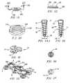
- FIGS. 1-5The preferred embodiment of the multiple locking anterior cervical locking plate 2 according to the present invention (here shown by way of example for use in a two level fusion (three adjacent vertebrae)) is shown in FIGS. 1-5 .
- Plate 2has a generally elongated form whose outline generally departs from rectangular due to the presence of lobes or lateral projections 4 at the corners and at the center of the sides of plate 2.
- Each lobe 4has a rounded outline and contains a respective circular bone screw receiving hole 6.
- Two additional intermediate circular bone screw receiving holes 8are located inwardly of the sides of plate 2 and are centered on the longitudinal center line of plate 2.
- Lobes 4give plate 2 additional strength in the region surrounding each bone screw receiving hole 6. It is recognized that other shapes for the plate 2 may be employed.
- the intermediate paired bone screw receiving holes 8are for use with a two level (three vertebrae) fusion.
- the intermediate bone screw receiving holes 8may be eliminated for a single level (two vertebrae) fusion, or additional intermediate bone screw receiving holes 8 may be added if additional levels are to be fused.
- Plate 2is further provided with three locking element holes 12, each of which in the preferred embodiment is internally threaded 3, and each of which is surrounded by a shallow countersunk region 14. As will be described in greater detail below bone screws are inserted in the bone screw receiving holes and a single pre-installed locking element associated with each of the locking element holes 12 locks a number of bone screws 30 in position at one time.
- the number of paired bone screw holesgenerally correspond to the number of vertebrae to be fused.
- a plate for a one level fusioncould have but a single locking element hole 12, while plates for fusing more than two levels (three vertebrae) could have additional middle locking element holes 12 corresponding to additional paired bone screw holes.
- each end locking element 20will lock three bone screws 30 in place, while the locking screw 21 in the central locking hole 12 locks two bone screws 30 in place.
- central locking element 25can also be configured so that four bone screws 30 are locked at one time.
- plate 2is shaped so that its bottom surface 27 (the surface which will be in contact with the vertebral bodies) has a bi-concave curvature, being concave both in the longitudinal plane (corresponding to its length) and in the plane transverse thereto, corresponding to its width.
- the concave curvature in the longitudinal planeconforms to the proper shape of the anterior aspect of the spine with the vertebrae aligned in appropriate lordosis.
- That longitudinal curveis an arc along the circumference of a circle (referred to herein as the "radius of curvature") 15.0 cm to 30.0 cm in radius and more preferably 20.0-25.0 cm in radius.
- the plate 2has a radius of curvature of a circle 15-25 mm in radius, but preferably 19-21 mm in radius. While the plate 2 may have a thickness between 2 to 3 mm, a thickness of between 2.25 and 2.5 mm is preferred.
- the contour of the plate of the present inventionprovides effective resistance to rocking of the plate 2 relative to the vertebral bodies about the longitudinal center line of the plate, thereby reducing stress on the plate 2 and bone screws 30, and preventing the soft tissues from becoming engaged beneath the plate.
- the plate 2will conform more closely to the facing bone surface; the plate 2 will project from the spine by a smaller distance; soft tissue will be prevented from sliding underneath the edges of the plate 2, where it could be subject to damage; and the angle of the bone screws 30, perpendicular to the plate when viewed from the side, when installed will be at a substantial converging angle, trapping the vertebral bone between the bone screws 30, and thus more strongly anchoring the plate to the spine.
- the bottom surface 27 of plate 2preferably has a porous, roughened, and/or textured surface layer and may be coated with, impregnated with, or comprise of fusion promoting substances (such as bone morphogenetic proteins) so as to encourage the growth of bone along the underside of the plate 2 from vertebrae to vertebrae.
- the textured bottom surface 27also provides a medium for retaining fusion promoting substances with which the bottom surface 27 layer can be impregnated prior to installation.
- the bottom surface 27 of plate 2may be given the desired porous textured form by rough blasting or any other conventional technology, such as etching, plasma spraying, sintering, and casting for example.
- the bottom surface 27is formed to have a porosity or pore size in the order of 50-500 microns, and preferably 100-300 microns. Fusion promoting substances with which the porous, textured bottom surface 27 can be impregnated include, but are not limited to, bone morphogenetic proteins, hydroxyapatite, or hydroxyapatite tricalcium phosphate.
- the plate 2may comprise of at least in part a resorbable material which can further be impregnated with the bone growth material so that as the plate 2 is resorbed by the body of the patient, the bone growth material is released, thus acting as a time release mechanism. Having the plate 2 being made from a material that is resorbable and having bone growth promoting material present permits the vertebrae to be fused in a more natural manner as the plate becomes progressively less load bearing thereby avoiding late stress shielding of the spine.
- At least one end of plate 2has a recess 18 that can cooperate with a compression apparatus, described in detail later in reference to FIGS. 36 and 38 .
- FIG. 6is a top plan view of the plate 2 of FIG. 1 with locking elements 20, 21 inserted into the locking element receiving holes.
- the locking elements 20, 21are in the form of screws that cooperate with the threaded interior 3 of the locking holes 12.
- Each of these locking elements 20, 21is shown in its initial open orientation, where the orientation of the cutouts 22 in the head 23 of each locking element 20, 21 is oriented so as to permit introduction of bone screws 30 into adjacent bone screw receiving holes 6,8 without interference by the head 23 of the locking element 20, 21. It is appreciated that other configurations of the head 23 are possible so as to permit introduction of bone screw into adjacent bone screw receiving holes without interference by the head 23.
- FIG. 8is a top view of another embodiment of plate 2 of FIGS. 1-5 , and is generally referred to as plate 120.
- Plate 120is provided with a longitudinally extending elongated slot 122 along its longitudinal axis which is superimposed on the middle locking hole 12.
- Elongated slot 122allows additional relative movement between plate 120 and a compression post 54 associated with a compression tool during the compression procedure, as discussed below.
- FIGS. 14 and 15an alternative embodiment of a multiple locking plate referred to by the number 70 is shown.
- plate 70rather than the threaded locking hole 12, a central opening 200 for receiving a removable rivet 202, of the type shown in FIGS. 17-20 , is provided.
- FIG. 15is a bottom plan view of the plate 70 shown in FIG. 14 .
- the contour of the plate 70is the same as that of the plate 2 shown in FIGS. 1-5 .
- the rivet 202is removable and fits within the unthreaded opening 200, comparable to the locking hole 12 and slot 122 described above.
- Other embodimentsmay employ a rivet that is not removable, but is manufactured as part of the plate 70 as would be used in the end locking holes 19 of FIGS. 14 and 15 .
- FIG. 22another alternative embodiment of a multiple locking plate is shown and is generally referred to by the number 230.
- the plate 230uses threaded caps, such as cap 300 shown in FIGS. 9 and 23 , for a locking element or preferably one with cut outs as described having an appearance in a top view such as the locking element in FIGS. 10-11 , for example.
- the central locking hole 602has an elongated slot 234 for providing an increased compression capability, as will be discussed further herein.
- FIGS. 10-13a first embodiment of a locking element 20, 21, 25 in the form of locking screws according to the present invention for use with plate 2 is shown.
- FIG. 10is a top plan view which illustrates the head 23 of the central locking element 25 shown in FIG. 7 .
- the shaft 46 of locking element 25is threaded 47 to mate with the threading 3 within the associated locking hole 12 of plate 2.
- each segment 49 on each side of cutouts 22 of the locking element 21has a bearing surface 48 formed at the lower surface of locking element head 23.
- the locking element head 23can be provided with two slots 42 for providing flexibility to the locking element head 23 to assist in the locking element's ability to ride over the top of the bone screw head 32 during the bearing action when the locking element is rotated.
- the bearing surfacecan be cammed, ramped or wedged. The cammed, ramped or wedged features can also be used with the other locking elements described herein.
- a ramp or wedge shaped surface 44may be used to increase the force applied to the bone screw head 32.
- the leading end of the ramped portion of the locking elementwould be lower than the prominence of the bone screw head 32 so that more force is needed to lift the locking element and untighten it than is needed for the locking element to remain tight and locked.
- the locking element heads 23need not have slots, be cammed, or have a ramped surface to achieve the locking of the bone screw 30 in place. Pressure, friction, interference fits, or other engagement means capable of preventing the locking element from moving from its locked position may be employed.
- the rivet 202shown in FIGS. 17-20 is intended for use in association with plate 70 shown in FIGS. 14-15 , is shown in detail in cross section in FIGS. 19 and 20 .
- the rivet 202has a head 204, a shaft 206, and an elongated bottom segment 208 for fitting within the corresponding opening 200 in the plate 70.
- the lower surface 210 of the head 204 of the rivet 202has an irregular surface which may be cammed, such as on the bottom of locking element 20, 21, for engaging the top surface 39 of the bone screw head 32.
- the upper surface of the elongated bottom segment 208can have an irregular surface for cooperating with the irregular surface of the bottom of the plate 70 to hold the rivet 202 in the locked position against the bone screw head 32, as shown in FIG. 15 .
- the rivet of FIG. 18is a separate, removable component from the plate, the rivets, and particularly those for use with the end locking holes, can be formed as part of the plate during the manufacturing process of the plate and rivet can be non removable.
- Each of the above embodimentsprovides tight attachment of the locking element relative the bone screw 30 and relevant plate.
- the locking elementcan be in the form of threaded locking cap 300 shown in FIG. 23 .
- the threaded locking cap 300has a thread 302 on its outer circumference corresponding to the thread 303 on the inner circumference of the locking element depressions 304 in the top of the plate 230 shown in FIG. 22 .
- the locking cap 300is relatively thin, particularly compared to its width.
- the top 305 of locking cap 300is provided with a noncircular through hole 306 for receiving a similarly configured driving tool.
- Plate 400has an opening in its top surface for insertion of the thin locking member 412, a recess 402 associated with each of the bone screw receiving holes 408 and a slot 410 in the side wall of the bone screw receiving holes 408 to permit the thin locking member 412, having a series of thin projections or blades 414, thinner than the slot 410, that give this locking member 412 an appearance similar to that of a propeller.
- the thin locking member 412is able to be rotated within the plate so as to not cover the bone screw holes, thus allowing the thin locking member 412 to be pre-installed prior to the installation of the bone screws by the surgeon. Limited rotation of the thin locking member 412 allows the blades 414 to protrude through the slot 410 and to cover a portion of the top of the associated bone screws 30.
- the blades 414 of the thin locking member 412are flexible and, when rotated, slide over the top surface 39 of the bone screw head 32 to lock the bone screw 30 in place.
- each of the embodiments of the locking elementis capable of locking more than one bone screw 30. It is appreciated that the various multiple locking plates and locking element combinations are capable of locking as many as four bone screws at once, but are equally effective for locking a lesser number or none at all, that is securing itself to the plate.
- each of the above described locking element embodimentsis to have a driver engagement means, in these cases for example, a recess 24 as large as the recess 34 in the bone screws 30 so that the same tool can be used to turn both the bone screws 30 and the locking elements.
- the locking elementsare sufficiently strong and have sufficient mass so as to be able to withstand being locked without breakage.
- each locking element 20, 21is provided at its center with a noncircular recess 24, such as shown in FIG. 9 which is engageable by an appropriate manipulation tool, such as shown in FIGS. 40-42 .
- the associated toolwould have a hex head, but other shapes of recesses in the head 23 may be used.
- the thread of each locking hole 12 and of each locking element 20, 21has a close tolerance so that they will reliably retain their orientations so as to permit introduction of bone screws 30 into bone screw receiving holes 6, 8 without interference.
- FIG. 83an alternative multiple locking plate 990 is shown having additional intermediate bone screw receiving holes 980 and associated locking elements 960 for locking bone screws 30 in place. Plate 990 allows for a more close spacing and more pairs of bone screw holes than the number of vertebrae to be engaged.
- FIGS. 84A-84Dvarious plates 700a-g used for a single level fusion are shown. Each of these plates 700a-g is designed to span one spinal segment consisting of one disc space and two adjacent vertebrae (containing the bone graft), and have bone screws inserted into the end of the vertebrae through the bone screw receiving holes 6 associated with the two adjacent vertebrae and then locked in place. As shown in Figures 84A-84D , one locking element 710, or two locking elements can be used to lock four bone screws in place. In FIGS. 84A-84D , each of the plates 700a-e is shown with the locking elements in their open orientation, before being rotated to lock the bone screws.
- Each of the above described platescan have the same generally biconcave contour as already described for conforming to the anterior aspect of the spine.
- FIGS. 24A and 24Bprovide a side view of one embodiment of a bone screw 30 according to the present invention.
- FIG. 27is a top view of the bone screw 30.
- a profiled recess 34which may have the same form as the recess 24 of each locking element 20, 21 in which case it may be turned with the same tool as that employed for turning locking elements 20, 21. It is appreciated that the driver engaging portion of the bone screw 30 could be slotted, and be either male or female (as is shown).
- the bone screw head 32is stepped, with the first lower head portion 35 being contiguous with the screw shank 33 and has a smaller diameter than the upper portion of the bone screw head 32.
- each bone screw receiving hole 6, 8 of the plate 2has a countersunk region 14 matching the diameter of the upper portion of the bone screw head 32 and dimensioned for an interference fit.
- the lower portion 35 of the bone screw head 32is dimensioned to achieve an interference fit with its associated portion of bone screw receiving holes 6, 8.
- the larger diameter upper portion of bone screw head 32assures that the bone screw 30 cannot be advanced completely through bone screw receiving holes 6, 8 of plate 2.
- the bone screw 30passes completely through the upper surface of the plate 2 without engaging the upper surface in any way.
- the head 32 of screw 30passes unobstructed through the upper surface of the plate until the lower surface of enlarged screw head 32 engages the upper face of the narrowed bone screw receiving portion at the midsubstance or below the midsubstance of the plate.
- Thisis considered optimal for allowing for the greatest screw to plate stability, even absent the lock, against all forces except those reverse the path of insertion, while still providing for the greatest plate strength beneath the bone screw head 23. That is, since the plate is of only generally 2-3 mm in thickness, a sheer vertical circumferential wall is best able to constrain the motion of a screw if the head is similarly configured and there is little tolerance between them.
- Placing the support of the head near the mid thickness of the plateis preferred as it allows the head to remain large to accommodate the recess for the driver without being weakened, while placing the support of the head away from the upper surface of the plate allows the screw head to be deep into the plate. Placing the support of the head at approximately the mid thickness of the plate assures plenty of plate material beneath the head to support while providing adequate head length above and below the contact point to prevent the contact point from acting as a fulcrum by providing adequate lever arms to prevent unwanted motion.
- bone screw head 32'is tapered in the direction from the top of the bone screw head 32' toward screw tip 36'. Again, the bone screw head 32' is dimensioned to achieve an interference fit in the associated bone screw receiving hole 6,8 when the bone screw 30' has been fully installed.
- bone screw receiving holes 6, 8need not be provided with a countersunk region 4.
- the bone screws 30 and 30'present a unique combination of a tapered screw shaft 33 and a helical thread 31.
- the diameter of screw shaft 33generally increases from a distal portion of the shaft near the screw tip 36 toward the proximal portion of the shaft near screw head 32. In the preferred embodiment, the rate of increase in diameter is also greater near the bone screw head 32. Such a shape avoids stress risers and provides increased strength at the screw-plate junction, where it is needed the most.
- the tapering of screw shaft 33may have a concave form, as shown in FIG. 24A , or may be linear. The distal portion of the screw shaft 33 may assume a constant diameter.
- the thread 31 of the bone screw 30has a substantially constant outer, or crest, diameter "d" from the proximal portion of the shaft below the bone screw head 32 to the distal portion of the shaft near the bone screw tip 36.
- the crest diameter of thread 31may be reduced for preferably one to two turns to facilitate the insertion and penetration of the bone screw 30 into the bone.
- the thread 31 of each bone screw 30has an outer diameter slightly smaller than the diameter of the lowest portion 35 of the bone screw head 32, which is adjacent the trailing, or upper, end of the associated thread 31.
- the thread 31is relatively thin, in the direction of the longitudinal axis of the screw, and tapers outwardly, and has a cross section of a triangle.
- the threaded portion of said screwhas a length from about 10 mm to about 22 mm (12 - 18 mm preferred) and a head length from about 1 mm to about 3 mm (2 - 2.5 mm preferred).
- the threaded portionshould have a maximum outside diameter from about 3.6 mm to about 5.2 mm (3.8 - 4.5 mm preferred) and the head has a diameter from about 3.8 mm to about 6 mm (4 - 5.5 mm preferred).
- the thread pitchis from about 1.25 mm to about 2.5 mm (1.5 - 2.0 mm preferred) and has a sharp and thin threaded profile.
- the apex of the two faces of the threadhave an angle of less than about 21 degrees (15 degrees preferred) and the base of the thread is less than about 0.60 mm thick (0.25 mm - 0.35 mm preferred).
- the screwhas a root diameter that increases from proximately above the tip of the shank, along the longitudinal axis to proximately below the head portion of the screw.
- the tip of the screw tipis fluted by at least one cut out section so as to make the screw self-tapping.
- the thread 31 of the bone screw 30has a thin profile, the thread will nevertheless be stronger than the bone into which it is introduced so that this thread will efficiently cut a thin helical groove in the bone tissue.
- the volume of bone that will be displaced by the thickness of the threadis minimized by the thin form of the thread, yet the substantial crest diameter of the screw thread maximizes the surface area of the threads in contact with the bone. While enlarging the screw shaft 33 diameter near the bone screw head 32 increases its strength where needed, reducing the screw shaft 33 diameter away from the bone screw head 32 where such strength is not required allows for the maximum area of engagement for the thread 31 to the bone.
- bone screw tip 36is provided with cutting flutes 38, to make the bone screw 30 self-tapping.
- the thread form of the present invention screwis itself more like a tap than a conventional screw in that the threads are very sharp and fluted.
- plates for fusing three adjacent vertebrae2 interspaces, or two spinal segments
- Each set of the bone screw receiving holes associated with a vertebraeis considered to be a segment of the plate so that for example, in FIG. 1 three segments are shown-- an upper, a central, and a lower segment. While the present discussion is in association with plates for use in fusing three vertebrae across two interspaces, it should be understood that longer and shorter plates having the appropriate number and location of bone screw receiving holes corresponding to the number of vertebrae to be fused are contemplated, and would take the form of the plates shown with fewer or more intermediate segments, such as the segment along line 9 of FIG. 1 , or the intermediate segments of the plates shown in FIGS. 82-84D .
- the surgeonHaving completed the interbody fusions, the surgeon removes any bone spurs or localized irregularities along the front of the spine of the area to be fused.
- the correct length plateis selected by the surgeon by measuring the distance on the spine by a caliper, ruler, template, and the like. That plate having a length sufficient to span the distance of the spine to be fused and to partially overlap a portion of each of the end vertebrae to be fused.
- the plateis placed into the wound and positioned to confirm positioning, length, and screw hole alignment relative to the segments of the spine to be fused.
- the platemay be attached to any of the vertebrae to be fused (by example only, here shown as the top vertebra).
- the pilot (guide) hole punch 60is attached to the plate 2 as per FIG. 32 , or alternatively, while not preferred the drill guide may be used as per FIG. 37 . In either event, the pilot hole forming means rigidly aligns with and is captured by the plate bone screw receiving hole wall.
- the pilot holeis then formed by impacting the pilot hole punch of FIG. 32 or drilling with the drill of FIG. 37 .
- the formation of the pilot holecan be done away with altogether and the correct screw selected so as to have a length less than the distance along its path to the posterior vertebral cortex can be directly inserted.
- the determination of the appropriate screw lengthis made by measuring or templating from radiographs, MRI's, or CT scans, or determined directly by measuring the depth of the disc space.
- FIGS. 41, 42show various ways of achieving such a fit of the driver and screw.
- clips, and springs and other meansare well known for temporarily and reversibly securing the screw to the driver.
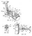
- the vertebrae 50a-care separated from one another by fusion graft blocks 51 which were previously installed in the spinal disc space between adjacent vertebrae 50 forming a fusion bone graft construct.
- Plate 2is shown in FIG. 31 with the locking elements 20, 21 removed in order to simplify the illustration. It will be understood, however, that in the preferred embodiment the locking elements 20, 21 can be, and preferably are, pre-installed in the positions shown in FIG. 6 prior to positioning plate 2 upon vertebral bodies of the vertebrae 50, thereby saving the surgeon time and trouble.
- Plate 2may be held in position by any known plate holding means, but preferably by the holding tools shown in FIGS. 45, 46 or 70 by the notches 142 in the sides of the compression arms 104, 130 of a vertebral compressor tool 100 shown in FIG. 39 , or as a further alternative, by the unitary plate holder similar to the FIG. 70 design.
- plate holder 870has a hollow tubular housing 872, with a central rod 874 having a thread 878 at one end for engaging one of the threaded locking holes 12 in the plate 2.
- the bottom end of the housing 872has projections 880, 882 that extend outwardly and then downwardly to fit into the bone screw receiving holes 8 of the plate 2 preventing the housing 872 from rotating.
- the central rod 874is located in the housing 872 such that it can be rotated by rotating a handle (not shown) which is fixed to the central rod 874 at its upper end.
- FIG. 46an alternative embodiment of the plate holder 890 is shown.
- a single solid member 890has a threaded projection 894 at its bottom end for attachment to the central threaded locking hole 12 in the plate.
- the bottom surface of the holder 890 of this embodimentis contoured so as to match the contours of the top surface of the plate adjacent to the locking hole 12, shown as a depression 14.
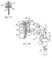
- a compression tool 100is shown with a toothed gear bar 102 having a first compression arm 104 secured to its free end.
- Compression arm 104has at its distal end a bore 106 for removably holding either a plate engaging element 108, shown in FIG. 36 , having a hook 110 at one end for engaging a depression or notch 18 in the end of plate 2, or for removably holding a compression post 54 shown in FIGS. 33-34 .
- FIG. 38a compression tool 100 is shown with a toothed gear bar 102 having a first compression arm 104 secured to its free end.
- Compression arm 104has at its distal end a bore 106 for removably holding either a plate engaging element 108, shown in FIG. 36 , having a hook 110 at one end for engaging a depression or notch 18 in the end of plate 2, or for removably holding a compression post 54 shown in FIGS. 33-34 .
- plate engaging element 108includes a shaft 112 that will be inserted into the corresponding bore 106 of compression arm 104, and a flange 115 for resting against the bottom face of bore 106 to accurately limit the depth of insertion of plate engaging element 108 into the bore 106.
- a ring spring 128, preferably of metal,is located in an annular depression of the shaft 112, for holding the plate engaging element 108 in the bore 106.
- compression tool 100includes a second moveable compression arm 130 movable along toothed bar 102 parallel to first compression arm 104.
- the distal end of the second compression arm 130also has a bore 132, the same as bore 106, that can receive a removable post 134. Bores 106 and 132 are the same so that either compression arm 104, 130 can be used to hold the removable post 134, permitting the compression tool 100 to be used in any orientation.
- Compression arm 130has a driving assembly consisting of a toothed wheel (not visible) which is engaged with the tooth gear 138 of bar toothed gear 102 and is connected to compression arm 130 such that compression arm 130 is movable along the length of toothed gear bar 102 by means of the rotation of handle 140, which is connected to the toothed wheel.
- the driving assemblyhas a self lock release mechanism whereby the movement of the two compression arms 104, 130 away from one another is prevented, without the activation of the release.
- toothed gear bar 102 and compression arms 104, 130have been described as being straight, it is possible that the toothed gear bar 102 and compression arms 104, 130 may be arcuately or otherwise shaped, so as to induce lordosis in the vertebrae, if so desired.
- the ends 144 of the compression arms 104, 130will be located in line with the fusion graft construct 51 which was placed in the disc space when plate 2 is properly positioned.
- a gapwill exist between plate 2 and each fusion graft construct 51, providing a space to accommodate the free ends of arms 104, 130 should they extend beyond the bottom surface of the plate 2.
- the same compression tool 100can also be used for compressing a plurality of cervical vertebral bodies with bone grafts interposed during the attachment of plate 2 to the vertebrae 50.
- plate 2is held by a suitable holder, in this case shown as the compression arms 104 and 130.
- a suitable holderin this case shown as the compression arms 104 and 130.
- the next stepis the formation of bone screw receiving holes 6 prior to installation of the bone screws 30 themselves in the vertebrae 50a. While the procedure is described as first attaching the plate 2 to the upper vertebrae 50a, the plate 2 can be attached to any of the vertebrae in any order. Different sized plates are used so that, as indicated above, the physician will select the appropriate sized plate in which the bone screw receiving holes 6, 8 are aligned with the three adjacent vertebrae 50a, 50b and 50c.
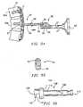
- Pilot holesare formed by a pilot hole forming apparatus 60 shown in FIGS. 31 and 32 .
- the bone screws 30may be inserted without the prior formation of an opening into the vertebrae as the bone screws 30 are preferably sharp pointed, self-tapping, and have at their tip a diminishing major diameter to assist the screw entering and pulling into the bone.
- a hole into the bone of the vertebraemay be formed prior to screw insertion, it is preferable that the hole be of a smaller diameter than the root diameter of the screw and for a different purpose than with the prior art.
- the hole drilledhad to be of a diameter equal to but preferably larger than the root (minor) diameter of the screw, as the screws were not self-tapping. It is desirous to create pilot holes to assure that a proper path for the bone screws 30 is maintained, and also to prevent damage to the vertebral bone during insertion of the bone screws 30.
- the pilot hole forming apparatus 60creates a more compact vertebral bone mass for reception of the self-tapping bone screw 30 used in this insertion.
- pilot hole forming apparatus 60includes a hollow cylindrical housing 62 having a bottom provided with a through hole 63.
- Housing 62contains a central shaft 64 which extends through the through hole 63 in the bottom of housing 62.
- the leading end 66 of shaft 64tapers gradually to a sharp point 65.
- Shaft 64is provided with a ring member 73 having a diameter which closely corresponds to the inner diameter of housing 62 to guide the travel of shaft 64 within housing 62.
- a compression spring 67is interposed between the ring member 73 and the bottom of housing 62. Compression spring 67 provides a bias force which normally urges the sharp point 65 into a retracted position within housing 62.
- shaft 64has an enlarged head 68 extending outside of the housing 62 which is intended to be manually depressed or struck by a percussion instrument in order to drive the sharp point 65 out of housing 62 and into a vertebral body 50a.
- Shaft 64is given a length, taking into account the length that spring 67 will have when fully compressed, to determine the maximum depth of the pilot hole formed in a vertebral body. The depth is selected to assure that the pilot hole does not reach the posterior cortex of the vertebral body, which borders the spinal canal.
- FIG. 32Certain structural features of hole forming apparatus 60 are shown in greater detail in FIG. 32 .
- the bottom end of housing 62has a projecting portion 69 dimensioned to fit precisely in a bone screw receiving hole 6 or 8 of plate 2.
- the bottom 71 of the projecting portion 69is flat in a plane perpendicular to the axis of housing 62.
- the lower end of the pilot hole forming apparatus 60is threaded so as to engage the thread in the bone screw receiving hole 6, 8 thereby fixing the plate and the pilot hole forming apparatus together, assuring a stable fit between the pilot hole forming apparatus and the plate 2.
- the diameter of the leading end 66 of the shaft 64is small since it has to fit within the small space left between the inside wall of the pilot hole forming apparatus. Since it is only a pilot hole for a self-tapping bone screw 30 that is being formed, the small diameter is satisfactory.
- a drill guide 80having a lower end as shown in FIG. 37 .
- the drill 80 guideconsists of a tubular member 82 and a small diameter lower end 84 which is dimensioned to achieve a precise interference fit in the associated bone screw receiving hole 6, 8 of plate 2.
- drill guide 80has an axial end surface in a plane perpendicular to the longitudinal axis of the drill guide 80 so that when the small diameter portion 84 is fitted into the bone screw receiving hole 6 and the surface surrounding the small diameter portion 84 is flush against the upper surface of plate 2, the axis of the drill guiding bore 86 in drill guide 80 will be precisely perpendicular to the upper and lower surfaces of the associated portion of plate 2.
- the bottom end of the drill guide 80can be threaded so as to engage to the threaded opening of plate 2.
- bone screws 30are threaded into the vertebrae 50 while holding the plate 2 firmly against the vertebrae 50 with compression tool 100 or plate holder 800. This locks the plate to the vertebrae 50a.
- Compression post 54is driven through the central locking hole 12 of plate 2 by means of insertion tool 90, shown in FIGS. 33 , 34 and 35 , into the vertebral bone of vertebra 50b, where it will be used in a subsequent step to apply a compression force between vertebrae 50a and 50b.
- Compression post 54consists of a shaft 56 having a sharp point 57 at its lower end, an enlarged central collar 58 which serves as a depth stop, and a circumferential groove 59 proximate its upper end, defining an enlarged head 55.
- Compression post insertion tool 90consists of a shaft 92 having a closed hollow portion 94 at its lower end 96 for receiving compression post 54 and an enlarged percussion cap 98 at its other end. Compression post insertion tool 90 also includes in its lower end 96 a second opening 95 having a recess 99 in its inside wall for permitting engagement of the enlarged head 55 on the compression post 54 within the depression 97. The second opening 95 is in communication with the hollow portion 94 of the insertion tool 90, as shown in FIG. 35 .
- the bore 132 in the second compression arm 130 of compression tool 100is then applied over compression post 54 in vertebrae 50b, and the plate engaging element 108 is inserted in the bore 106 of the first compression arm 104 of compression tool 100.
- the hook 110 of the plate engaging element 108 shown in FIG. 36is fitted into the notch 18 at the end of the plate 2 which is fixed by the bone screws 30 inserted into the vertebra 50a, as shown in FIG. 38 .
- the compression tool 100can be rotated so that the first compression arm 104 is now at the bottom and is able to fit over the compression post 54 in vertebrae 50c.
- bone screw pilot holescan be formed in vertebral body 50b by means of pilot hole forming apparatus 60, as described above, for insertion of bone screws 30 into bone screw receiving holes 8 of bone plate 2, fixing the plate 2 to the adjacent vertebrae 50b. Compression tool 100 can then be withdrawn by activation of the release.
- FIG. 39illustrates the use of compression tool 100 to induce compression between the lower two vertebral bodies 50b and 50c after bone screws 30 have been installed in the middle vertebral body 50b as just described.
- compression post 54remains in place in the middle vertebral body 50b and an additional compression post 54 is driven into the lower vertebral body 50c by means of pilot hole forming tool 60 distal to the plate itself in the recess between the end projections 4 to allow for the lower compression post 64 to be moved towards vertebrae 50b upwardly as shown.
- the original compression post 64is inserted in bore 106 in the first compression arm 104 and the additional compression post 54 is inserted into the bore 132 of the second compression arm 130 of compression tool 100.
- the turning of the handle 140results in the two compression arms 104, 130 moving towards one another, resulting in the compression post 54 in vertebrae 50c moving towards the upper compression post 54 in vertebrae 50b, once again compressing the fusion graft construct 51 between vertebrae 50b and 50c.
- the upper compression post 54 in vertebrae 50bcan not move since the vertebrae 50b has been fixed to the plate by the insertion of the bone screws 30 in the bone screw receiving holes 8 of the plate 2.
- only the lower compression post 54 and vertebrae 50ccan move.
- the pilot holes associated with vertebrae 50care formed and the bone screws 30 are inserted through bone screw receiving holes 6.
- the compression tool 100is then removed.
- Compression post 54is then extracted from the vertebrae by inserting it in the second opening 95 of the compression post insertion/removal tool 90, so that it engages the enlarged head 55 of the end of compression post 54 by depression 97, as shown in FIG. 34 .
- the hook 110 of compression tool 100may engage the notch 18 in the end of the plate 2, and the other compression arm of the compression tool 100 may engage the compression post 54 in the third adjacent vertebrae 50c.
- plate 2has a recess end cut out portion between the lobes at the end of the plate for insertion of the compression post 54 in the vertebrae. Otherwise, there may not be room below the end of the plate 2 for insertion of the compression post 54.
- FIG. 40is a perspective view showing the plate 2 of FIGS. 1-5 , at a stage of a surgical procedure when bone screws 30 have been fully installed in three adjacent vertebrae 50a, 50b and 50c, and locking screws 20, 21 have been rotated through an angle of about 90° to lock three bone screws 30 in place; the left-hand locking screw 20 as viewed has been rotated through an angle of about 60° to lock three bone screws 30 in place and the central locking screw 21 has been rotated through an angle of about 90° to lock two other bone screws 30 in place.
- one of the camming surfaces 44 of each locking screw 20, 21rests atop the screw head 32 of a respective bone screw 30.
- Installation of the locking cap 300can also be performed with a tool 220 such as shown in FIGS. 41 and 42 having a suitably shaped tip 222 with a length corresponding to the depth of hole 306 in a locking cap 300.
- the end 222 of tool 220is flared just proximal to the most distal end so that it creates a friction fit with the screw cap 300 for ease of manipulation, and prevents the screw cap 300 from falling off the tool 200.
- FIG. 43is a cross-sectional view in the plane of the center of the two end locking screw holes 6 of plate 2, with two bone screws 30 in their installed positions and locking element 21 in its locking position.
- FIG. 44is an enlarged view of one of the bone screws 30 in plate 2 of FIG. 43 .
- the axis of each screw 30is generally perpendicular to tangents to the upper and lower surfaces of plate 2 at points which are intersected by the longitudinal axis of the associated bone screw 30.
- bone screws 30can be directed so as to converge toward one another at a desired angle.
- the axis of the two bone screws 30 shown in FIG. 18may subtend an angle of about 45°.
- the curvature of the plate from side to sidemay be so as to conform to the surface of the anterior aspect of the human adult cervical spine and the axis of the paired screw hole may deviate from being perpendicular to the plate when viewed on end to achieve optimal convergence.
- a "claw" of a rigid triangular frame structureis obtained at each pair of bone screws 30 such that the attachment of plate 2 to the vertebral bodies 50a, 50b and 50c would be highly secure due to the trapping of a wedged mass of bone material between the angled bone screws triangle, even if any thread stripping should occur.
- the "claw”may be further formed by three angled bone screws in a tripod configuration or by four bone screws in a four sided claw configuration.
- a plating system according to each of the above embodimentscan be installed in the same manner as described above, and using the same instruments and tools, as illustrated and described above with respect to the first embodiment.
- the compression operationswould be performed by means of slot 604 instead of the middle locking screw hole 12.
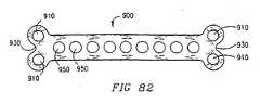
- a plate 900is shown in which there are a pair of bone screw receiving holes 910 at its ends 930 and a number of bone screw receiving holes 950 along the longitudinal axis of the plate 900.
- the additional bone screw receiving holes 950permit a single plate to be able to be aligned with a number of different sized vertebrae disc spaces, and bone fusion grafts.
- the plate of the present invention shown in FIGS. 1-5requires that a properly sized plate be selected by the surgeon so that each pair of bone screw receiving holes 6, 8 line up with the appropriate vertebrae. This requires a number of different sized plates to be available for optimum attachment of the bone screw receiving holes to each of the vertebrae.
- the close spacing and increased number of central openingspermit the surgeon to locate at least one appropriate opening to be aligned with each of the intermediate vertebrae, and/or bone grafts.
- bone screws described in this applicationcould be used in other parts of the body, again being modified so as to serve their intended purposed, depending on the size of the body part in which they are to be installed.
Landscapes
- Health & Medical Sciences (AREA)
- Orthopedic Medicine & Surgery (AREA)
- Surgery (AREA)
- Life Sciences & Earth Sciences (AREA)
- Public Health (AREA)
- Veterinary Medicine (AREA)
- Nuclear Medicine, Radiotherapy & Molecular Imaging (AREA)
- Engineering & Computer Science (AREA)
- Biomedical Technology (AREA)
- Heart & Thoracic Surgery (AREA)
- Medical Informatics (AREA)
- Molecular Biology (AREA)
- Animal Behavior & Ethology (AREA)
- General Health & Medical Sciences (AREA)
- Neurology (AREA)
- Oral & Maxillofacial Surgery (AREA)
- Dentistry (AREA)
- Surgical Instruments (AREA)
- Prostheses (AREA)
- Adornments (AREA)
- Orthopedics, Nursing, And Contraception (AREA)
- Materials For Medical Uses (AREA)
- Professional, Industrial, Or Sporting Protective Garments (AREA)
- Compounds Of Unknown Constitution (AREA)
- Diaphragms For Electromechanical Transducers (AREA)
- Color Television Systems (AREA)
- Ultra Sonic Daignosis Equipment (AREA)
- Solid-Sorbent Or Filter-Aiding Compositions (AREA)
Abstract
Description
- The present invention relates to a plate according to the preamble of claim 1.
- It is current practice in the art to use cervical plating systems for this purpose. Such systems are composed essentially of plates and screws for aligning and holding vertebrae in a desired position relative to one another. The earliest such devices consisted of stainless steel.plates and screws and required that the screws passed entirely through the vertebrae and into the spinal canal in order to engage the strong bone tissue (the posterior cortex) of the vertebral bodies. This required the ability to observe or visualize this area radiographically, which is not always possible, especially in the lower cervical spine where the vertebrae may be hidden radiographically by the shoulders.
- In order to form holes in the vertebral bodies for insertion of each screw, a drilling operation was performed, followed by a tapping operation. Each of these operations involved the passage of an instrument entirely through the associated vertebral body and into the spinal column. Thus, these instruments come into close proximity to the spinal cord and the dural sac which are in close proximity to the back surfaces of the vertebral bodies. Any procedure which introduces an object into the spinal canal presents serious risks which are of concern to the surgeon.
- The conventional technique of forming a bone screw receiving hole in vertebral bodies by drilling has a number of significant disadvantages. For example, drilling removes bone material, leaving a void and resulting in a loss of bone material. Drilling also causes microfracturing of the bone at the drill bit-bone interface and the resulting fracture lines tend to propagate in directions perpendicular to the wall of the hole. More specifically, the bone material is essentially a type of ceramic which exhibits a brittle pattern of fracture formation and propagation in response to drilling. Furthermore, drilling generates heat which can result in thermal necrosis of the bone material precisely at the interface between the bone and a subsequently installed screw, where necrosis is most harmful. Any bone which does experience necrosis will subsequently be resorbed by the body as part of the bone repair process and this can lead to the loosening of the screw.
- Another problem with drilling is that the path of the drill bit is difficult to control and since the drill bit operates by rotation, it can wind up soft tissue about the associated plate. In addition, unless great care is taken, the drill bit may be driven significantly past the posterior cortex and cause irreparable harm within the spinal canal. Finally, a drill bit may bind and fracture within the vertebral body and can then cause serious injury as the still rotating portion of the drill bit passes into the wound, while the portion of the bit which has broken off may either protrude dangerously from the vertebral body or may be broken off flush with the upper surface of the body so as to be irretrievably embedded therein. In any event, the steps that must be taken to retrieve the broken-off portion of a drill bit will inevitably prolong and complicate the surgical procedure.
- In known plating systems, there have been problems with loosening and failure of the hardware, breakage of the screws and plates, and backing out of screws into the patient's throat area. These occurrences generally require further surgical procedures to replace the broken parts or the plates and screws entirely, and to repair any damage that may have been caused.
- Other problems which have been encountered with known systems result from the failure of the screws to achieve a sufficient purchase in the bone and the stripping of the screws.
- Also, the use of the known plating systems may result in a loss of lordosis, which is the normal curve of the cervical spine when viewed from the side.
- Known plating systems additionally experience problems in connection with those procedures where bone grafts are placed between vertebral bodies to achieve an interbody fusion which heals by a process called "creeping substitution". In this process, bone at the interface between the graft and a vertebra is removed by a biological process which involves the production of powerful acids and enzymes, as a prelude to invasion of the interface by living tissue and the deposition, or growth, of new bone. While the plates allow for proper alignment of the vertebrae and their rigid fixation, they can therefore, at the same time unfortunately, hold the vertebrae apart while the resorption phase of the creeping substitution process forms gaps in the bone at the fusion site with the result that the desired fusion does not occur. Such failure is known as pseudoarthrosis. When such a failure occurs, the hardware itself will usually break or become loosened from the spine, thus requiring a further surgical procedure to remove the broken components and another surgical procedure to again attempt fusion.
- In response to the problems described above, a second generation of plating systems has been developed and/or proposed. These include a system disclosed in
U.S. Patent Nos. 5,364,399 to Lowery and5,423,826 to Coates and Lowery, as well as cervical spine locking plating systems offered by SYNTHES Spine, the DANEK ORION plate, the CODMAN SHURTLEFF plate, and the SMITH NEPHEW RICHARDS plate, among others. The saidUS 5,364,399 discloses a plate of the initially-mentioned type according to the preamble of claim 1. The systems' forming members of this second generation have a number of common properties. They are all made of either a titanium alloy or pure titanium rather than stainless steel, to minimize adverse tissue reactions and are MRI compatible, which stainless steel is not. The screws and the plates have been given increased thickness in order to achieve increased strength. The screws have larger diameters to improve their purchase without requiring that they engage the posterior cortex of the vertebral bodies. Some mild longitudinal contouring of the plates is employed to allow for some lordosis, and/or limited transverse contouring to better follow the generally curved aspect of the front of the vertebral bodies. Mechanisms are employed for securing the vertebral bone screws to their associated plates in a manner to prevent the screws from backing out. While this second generation of plating systems represents a significant improvement over earlier systems, certain existing problems persist, while new problems have been created. - For example, since the screws no longer extend into the posterior cortex, it is common for the threads in the tapped screw hole to become stripped and for the screws to fail to gain a suitable purchase. In addition, screw breakage continues to be experienced and occurs most commonly at the junction of the screw to the posterior aspect of the plate. The screws employed in both the SYNTHES system and the SMITH NEPHEW RICHARDS system are particularly vulnerable to this problem because those screws are hollow at the level where they attach to the plate to permit the internal reception of locking screws.
- In an attempt to prevent screw to plate junction breakage of the screw, more recent designs of screws have an increasing root diameter from tip to head, which thus far has resulted in a near useless stubby and blunt thread near the screw head with little holding power and little tactile feedback to the surgeon to signal the completion of tightening prior to stripping of the screw within the bone. Based on empiric studies testing these prior art screws, the use of a pretapped hole, rather than a self-tapping screw, was found to be preferred for pullout strength and thus these screws have not been self-tapping and thus the screw holes must be pre-tapped. Since the thread cutting portion of a tap is necessarily sharp and rotated to work, there is a serious risk of damage to the surrounding soft tissues when it is used. This is compounded by the fact that the plates employed in these systems do not provide sufficient long axis contouring to make full allowance for lordosis and do not have sufficient transverse contouring to prevent rocking of the plate about its longitudinal axis and to conform to the anterior shape of the vertebral bodies, so that these plates do not prevent soft tissue from creeping in from the sides and beneath the screw holes thus exposing these tissues to damage by the drill and the tap. While it is possible, at the time of surgery, to make some change in the contouring of these plates, this is generally limited to contouring of the longitudinal axis and quite often causes distortion of the plate's bone screw holes and screw hole to plate junctions in a manner which has an adverse effect on the screw-plate interlock. Lack of proper contouring prevents these plates from having an optimally low profile relative to the spine.
- In some of the second generation cervical plating systems, screw backout continues to occur, because these plates could not be designed to allow for the locking of all of the screws. Specifically, while the designers of these plates recognized the importance of securing the bone screws to the plates, they were unable to lock all of the screws and had to settle for leaving some of the screws unlocked.
- Furthermore, several of these second generation systems utilize tiny and delicate "watchmaker" parts to achieve interlocking. These parts are characterized by the need to engage them with particularly delicate small ended screw drivers. These interlocking components are easily rendered ineffective by any effort to alter the contours of a plate during surgery.
- Despite the improvement of these second generation plating systems over the first problems, the problems still persist, the most important of which is pseudoarthroses, and particularly "distraction pseudoarthroses". Although these second generation plates have clearly led to an increase in fusion rate, when a failure to produce fusion occurs, it is generally accompanied by bone resorption along a line at the graft-to-vertebra junction, which can be seen on a radiograph.
- In the case of the weak first generation plates and screws, the plates might hold the vertebrae apart, preventing fusion, but only until the hardware would break, relieving the distraction, and then allowing the fusion to occur. The second generation systems of plates are too strong to allow this to occur, thus requiring further surgical procedures for the correction of the pseudoarthroses.
- Compression plates are well-known and are widely used in orthopedic surgery for the stabilization of tubular bones, and sometimes also flat bones. Such plates may rely on some external compression means or may be self-compressing, relying on the ability of the screw head to slide within a ramped slot such that the tightening of the bone screws through the plate imparts a linear motion perpendicular to the screw axes.
U.S. Patent No. 5,180,381 discloses an attempt to employ such a mechanism in connection with anterior spinal fixation. - However, it has been found that all of the proposed self-compressing plating systems have in common the need for a screw to engage both a proximal and a distal cortex, (bone casing of very dense bone material), so as to anchor the screw tip in a manner to allow the plate to move relative to the screw when tightened rather than allowing the plate to drag the screw off axis. However, as already discussed earlier herein, when a screw is to engage the posterior cortex of the vertebral body, it is necessary for the drill and the tap which form the screw hole, as well as the screw tip itself, to all enter the spinal canal, thereby exposing the spinal cord to damage.
- While the system disclosed in
U.S. Patent No. 5,180,381 avoids such danger by engaging the vertebral body end plate instead of the posterior vertebral body cortex, the path of the screw is of necessity quite short, so that there is very little opportunity for the screw threads to achieve additional purchase within the vertebral body. It would therefore appear that to the extent that the device disclosed inU.S. Patent No. 5,180,380 is able to achieve its stated objectives, it would pull the front of the spine together more than the back and would not appear to compress the back of the vertebral bodies at all, thus producing an undesirable iatrogenic loss of the normal cervical lordosis. Such a situation is disruptive to the normal biomechanics of the cervical spine and potentially quite harmful. - The creation of compression between adjacent vertebrae would offer a number of advantages, including reduced distraction pseudoarthrosis, increased surface area of contact between the graft and vertebrae as slightly incongruent surfaces are forced together, increased osteogenic stimulation, since compressive loads stimulate bone formation, and increased fusion graft and spinal segment stability.
- Among the new problems created by these second generation systems is a tendency for the small "watchmaker" parts used to lock the bone screws to the plate to fall off of the driver used for attaching those parts, or out of the associated plates and to become lost in the wound. In addition, these small parts are quite fragile and require specialized additional instruments for their insertion and/or manipulation. Furthermore, incorrect bone screw placement relative to the axis of a plate hole may render the screw locking mechanism unworkable or may cause sharp and jagged shavings of titanium to be formed as a locking screw is driven into contact with an improperly seated bone screw. The means for establishing bone screw to plate hole alignment and preparation are less than reliable. Furthermore, most of these second generation systems lack a reliable and effective means for positioning and holding the plate during attachment.
- Specific features of various prior art systems will be summarized below.
- The system disclosed in
U.S. Patent Nos. 5,364,399 and5,423,826 , cited earlier herein, includes a thin stainless steel plate which allows for side-by-side or offset bicortical screw placement, the plate having a combination of screw holes and slots. - The "Acromed" system includes a titanium plate and screws which require bicortical screw placement. This system does not include any locking means for the bone screws.
- The system disclosed in
U.S. Patent No. 5,180,381 includes an "H" shaped plate having a combination of ramped slots and a hole which requires bicortical screw placement at a 45° angle to the plane of the plate. This patent discloses that this angular positioning is for the purpose of producing compression. - The SYNTHES Morscher plate system employs hollow, slotted screw heads. The screws are placed unicortically so that the heads, when properly aligned, come to rest in the upper portion of the plate holes.
The upper portion of each screw is internally threaded to receive a tiny screw which is screwed into the bone screw head in order to increase the interference fit between the bone screw head and the wall of the associated plate hole. - In the system disclosed in
U.S. Patent Nos. 5,364,399 and5,423,826 , use is made of pairs of unicortical bone screws that may be locked in place at both ends of the associated plate by locking screws which have a small diameter shank and a large head. At each end of a plate two bone screws may be locked in place by a single locking screw which is situated between the bone screws. Generally, the plate is provided, between its two ends, with a diagonal slot or slots for receiving one or more additional screws, each additional screw being securable in a bone graft or a respective vertebra which is spanned by the plate. There is no locking screw associated with these intermediate bone screws to lock the bone screws to the plate. - The Codman Shurtleff plating system utilizes the side of a preinstalled rivet having a head rotatable to press against the side of the head of a bone screw so as to secure that one screw to the plate. The plates of this system also are provided with holes for receiving intermediate screws, but these screws are not associated with any locking means.
- While the designers of the last-mentioned systems recognized the importance of locking the bone screws in position on their associated plates, they did not provide for any locking of the intermediate bone screws in their associated holes.
- In an earlier version of the Codman Shurtleff system, the locking mechanism was a lever pivotable about a shaft passing entirely through the plate and then flared so as to retain the shaft within the plate. The lever was rotated after the bone screw had been inserted to engage the head of the bone screw and thus secure the bone screw to the plate.
- Based on a consideration of the features of all of the known cervical plating systems, it appears that there remains a need for an improved system having the following combination of features:
- 1) The plate should be sufficiently strong to perform its intended function without mechanical failure;
- 2) The plate should be preformed in three dimensions so as to anatomically conform in both the longitudinal and transverse planes to the anterior cervical spine;
- 3) The plate should be constructed so that all of the bone screws are generally perpendicular to the plate when viewed from the side, but pairs of screws are highly convergent corresponding to any vertebral level when viewed from the bottom, or on end;
- 4) Each pair of screws engages in a respective vertebra and the high convergence of screws in a pair allows the length of the screws which engage the bone to be longer and still remain within that vertebra and provide a safer and stronger engagement with the vertebrae;
- 5) The system should include bone screws which are capable of achieving enhanced purchase within the bone of the vertebral body and without the need to penetrate the posterior vertebral cortex and enter the spinal canal;
- 6) Use should be made of a screw which is self-tapping, thereby eliminating the need for separate tapping steps;
- 7) A reliable means should be provided for engaging and manipulating the plate during installation;
- 8) The plate should be engageable with an instrument means which can reliably produce bone screw holes which are coaxial with the screw holes in the plate;
- 9) It should be possible to prepare the vertebral bone to receive the bone screws so as to produce a stronger connection and a reduced danger of thread stripping by means of a pilot hole punch creating a pilot hole for the bone screws;
- 10) Alternatively to the use of a pilot hole punch, a relatively (compared to the overall root diameter of the screw) small diameter drill may be used to create the pilot hole.
- 11) Means should be provided for locking each and every bone screw in position relative to the plate, and the locking means should be of sufficient size and strength to reliably perform its intended functions;
- 12) Bone screw locking means should preferably be retainable by the plate prior to bone screw insertion, or should be reliably attachable to a driver to prevent any small parts from becoming loose in the wound; and
- 13) The system should be capable of effecting compression of the vertebral segments to be fused while maintaining and/or restoring lordosis.
- An object of the present invention is to provide a vertebral plate in which the physician does not have to attach the locking mechanism to the plate as a separate procedure during the operation.
- Another object of the invention is to provide plate in combination with a bone screw, wich allows for the intersegmental compression of the spinal segment (compression of the adjacent vertebrae and the fusion graft in the disc space between the adjacent vertebrae) in lordosis, and similarly, where desired, multisegmental compression.
- The invention provides a plate having the features of claim 1 and a plate in combination with at least one bone screw having the features of
claim 39. Further embodiments of the invention are described in the dependent claims. - The above and other objects and features of the invention will become more readily apparent from the following description of preferred embodiments of the invention, provided with reference to the accompanying drawings, which illustrate embodiments of the invention solely by way of non-limiting example.
- Preferably, the plate has a length sufficient to span a disc space and to overlap, at least in part, at least two adjacent cervical vertebrae, a substantial portion of the lower surface of the plate preferably being bi-concave, that is concave curved along a substantial portion of the longitudinal axis of the plate and concave curved along a substantial portion of the transverse axis of the plate. The lower surface of the plate may also textured and/or treated to induce bone growth along the lower surface of the plate which contacts the cervical vertebrae. The plate and its component parts, may be made of any implant quality material suitable for use in the human body, and the plate and associated component may be made of a bioresorbable material.
- Bone screws are each insertable into a respective bone screw receiving hole for attaching the plate to a vertebra. A locking element, is engageable to a locking element receiving recess and has a head formed to lock the bone screws to the plate. A single locking element locks a number of different bone screws in place. The locking elements are pre-installed prior to use by the surgeon in a manner so as to not impede installation of the bone screws.
- As a result, the problems previously associated with the locking screws of the type applied after the insertion of the bone screws, including the problems of instrumentation to position and deliver to the plate the locking means, backing out, breakage, stripping and misthreading associated with the prior art more delicate locking screws resembling "watchmaker's parts", are eliminated.
- The locking elements can be in many forms to achieve their intended purpose, such as, but not limited to, screws, threaded caps, rivets, set screws, projecting elements, and the like.
- The plating system does not require that the head of the bone screw be hollow, or that additional holes be placed through the plate in addition to those provided for the passage of the bone screws. It will be appreciated that bone screws are weakened when their heads are hollow and that plates are weakened when they are provided with additional holes.
- Additionally, the plate of the disclosed systems permit the proper aligning of the holes in the plate for the bone screws and for the plate to be easily applied to the vertebrae in compression. The plates include appropriate slots and engagement means for engaging compression instrumentation, described in detail below, for applying a compression force between adjacent vertebrae to which the plate is attached, in a reliable and easy manner.
FIG. 1 is a top perspective view of a first embodiment of a cervical spine multiple locking plate.FIG. 2 is a top plan view of the cervical spine multiple locking plate shown inFIG. 1 .FIG. 3 is a side elevational view of the cervical spine multiple locking plate shown inFIG. 1 .FIG. 4 is an end view of the cervical spine multiple locking plate shown inFIG. 1 .FIG. 5 is a bottom plan view of the cervical spine multiple locking plate shown inFIG. 1 .FIG. 6 is a top plan view of the cervical spine multiple locking plate shown inFIGS. 1-5 , with locking elements installed in an open configuration.FIG. 7 is a top plan view of a modification of the plate ofFIGS. 1-6 with a four bone screw locking element in place.FIG. 8 is a top plan view of a further embodiment of a cervical locking plate ofFIG. 1 with an elongated central slot for increased compression capability.FIG. 9 is a top plan view of a locking element not being part of the invention for use with the plates ofFIGS. 1-6 .FIG. 10 is a top plan view of a locking element for use with the central opening of the plate ofFIGS. 7 and22 .FIG. 11 is a top plan view of a locking cap for use in the end openings shown inFIGS. 1, 6, and 7 .FIG. 12 is a side elevational view of the locking element ofFIG. 16 .FIG. 13 is a side elevational view of another embodiment of the locking element ofFIG. 16 .FIG. 14 is a top perspective view of an alternative embodiment of cervical spine multiple locking plate for use with locking rivets.FIG. 15 is a bottom plan view of the cervical spine multiple locking plate ofFIG. 14 .FIG. 16 is a top plan view of a two bone screw locking element.FIG. 17 is a top plan view of an alternative embodiment of a four bone screw locking element having head slits for increased flexibility of the locking tabs.FIG. 18 is a bottom plan view of a rivet type locking element for use with the central opening of the plate ofFIG. 14 .FIG. 19 is a side elevational view of a rivet locking element not according to the invention.FIG. 20 is a top perspective view of the bottom portion of the head of rivet ofFIG. 19 viewed along lines 20-20.FIG. 21 is a top perspective view of the head portion of a three bone screw locking element.FIG. 22 is a top perspective view of a third embodiment of a cervical spine multiple locking plate utilizing locking elements in the form of threaded caps.FIG. 23 is a side elevational view of a locking element not according to the invention for use with the plate ofFIG. 22 .FIG. 24A is a side elevational view of a bone screw in accordance with the present invention.FIG. 24B is an enlarged side elevational view of the bone screw ofFIG. 24A .FIG. 25 is a side elevational view of an alternative embodiment of a bone screw in accordance with the present invention.FIG. 26 is a bottom end view of the bone screw shown inFIG. 24A .FIG. 27 is a top end view of the bone screw shown inFIG. 24A .FIG. 28 is a top perspective view of a fourth embodiment of a cervical spine multiple locking plate.FIG. 29 is a top perspective view of a locking element for use with the plate ofFIG. 28 .FIG. 30 is a partial side sectional view of the plate ofFIG. 28 along lines 30-30 with a bone screw in place.FIG. 31 is a top perspective view of the plate ofFIG. 1 positioned against the anterior aspect of three successive vertebral bodies in the cervical spine, a plate holder, and an instrument for forming bone screw receiving holes in to the vertebral bodies.FIG. 32 is a cross-sectional view of a portion of the bone forming device shown inFIG. 31 viewed along lines 32-32.FIG. 33 is a side elevational view in partial cross section illustrating a compression post tool and a compression post engaged to it for insertion into a vertebral body.FIG. 34 is a side elevational view in partial cross section of the compression post tool engaged for removal of the compression post from the vertebral body.FIG. 35 is a bottom end view of the compression post tool ofFIG. 34 .FIG. 36 is a side elevational view of a plate engaging hook for use with the compression apparatus shown inFIG. 38 .FIG. 37 is a cross-sectional view through the plate of an alternative hole forming instrument in the form of a drill guide and drill for use during the plate installation procedure.Fig 38 is a side elevational view showing intersegmental compression of the spine and compression apparatus.FIG. 39 is a view similar to that ofFIG. 38 showing the compression apparatus in a further stage of the plate installation procedure.FIG. 40 is a top perspective view showing the locking of the bone screws to the plate.FIG. 41 is a partial side sectional view of a locking element attached to a driver instrument.FIG. 42 is a partial side sectional view of another embodiment of the locking element attached to a driver instrument.FIG. 43 is a partial cross-sectional view showing a cervical plate, locking element, and bone screws along lines 43-43 ofFIG. 40 .FIG. 44 is an enlarged portion of detail alongline 44 ofFIG. 43 .FIG. 45 is a side view in partial cross section of a plate holder attached to a plate.FIG. 46 is a side view in partial cross section of another plate holder attached to a plate.FIG. 82 is a cervical spine plate for use in stabilizing multiple segments of the spine.FIG. 83 is a view of a cervical spine multiple locking plate not according to the invention for use in stabilizing multiple segments of the spine.FIG. 84A-84D are various embodiments of cervical spine multiple locking plates for use in stabilizing a single segment of the spine.- The present invention will be described first in association with the preferred embodiment of the plate system in which a plurality of bone screws are locked in place with one locking element. This is referred to as the multiple locking plate system. The multiple locking plates will be described, then the locking elements for locking the bone screws to the plate, then the bone screws associated with the multiple locking plates, and finally the instrumentation and method of installation of the multiple locking plates.
- The preferred embodiment of the multiple locking anterior
cervical locking plate 2 according to the present invention (here shown by way of example for use in a two level fusion (three adjacent vertebrae)) is shown inFIGS. 1-5 .Plate 2 has a generally elongated form whose outline generally departs from rectangular due to the presence of lobes orlateral projections 4 at the corners and at the center of the sides ofplate 2. Eachlobe 4 has a rounded outline and contains a respective circular bonescrew receiving hole 6. Two additional intermediate circular bonescrew receiving holes 8 are located inwardly of the sides ofplate 2 and are centered on the longitudinal center line ofplate 2.Lobes 4give plate 2 additional strength in the region surrounding each bonescrew receiving hole 6. It is recognized that other shapes for theplate 2 may be employed. - The intermediate paired bone
screw receiving holes 8 are for use with a two level (three vertebrae) fusion. The intermediate bonescrew receiving holes 8 may be eliminated for a single level (two vertebrae) fusion, or additional intermediate bonescrew receiving holes 8 may be added if additional levels are to be fused. Plate 2 is further provided with three locking element holes 12, each of which in the preferred embodiment is internally threaded 3, and each of which is surrounded by a shallow countersunkregion 14. As will be described in greater detail below bone screws are inserted in the bone screw receiving holes and a single pre-installed locking element associated with each of the locking element holes 12 locks a number of bone screws 30 in position at one time.- The number of paired bone screw holes generally correspond to the number of vertebrae to be fused. A plate for a one level fusion could have but a single
locking element hole 12, while plates for fusing more than two levels (three vertebrae) could have additional middle locking element holes 12 corresponding to additional paired bone screw holes. In the embodiment illustrated inFIGS. 1-6 , eachend locking element 20 will lock threebone screws 30 in place, while the lockingscrew 21 in thecentral locking hole 12 locks twobone screws 30 in place. As shown inFIG. 7 ,central locking element 25 can also be configured so that fourbone screws 30 are locked at one time. - As shown particularly in
FIGS. 3, 4 and 5 ,plate 2 is shaped so that its bottom surface 27 (the surface which will be in contact with the vertebral bodies) has a bi-concave curvature, being concave both in the longitudinal plane (corresponding to its length) and in the plane transverse thereto, corresponding to its width. The concave curvature in the longitudinal plane conforms to the proper shape of the anterior aspect of the spine with the vertebrae aligned in appropriate lordosis. That longitudinal curve is an arc along the circumference of a circle (referred to herein as the "radius of curvature") 15.0 cm to 30.0 cm in radius and more preferably 20.0-25.0 cm in radius. Viewed on end inFIG. 4 , theplate 2 has a radius of curvature of a circle 15-25 mm in radius, but preferably 19-21 mm in radius. While theplate 2 may have a thickness between 2 to 3 mm, a thickness of between 2.25 and 2.5 mm is preferred. - Having the
bottom surface 27 ofplate 2 contoured so that it is able to lie flush against the associated vertebral bodies is in contrast to conventional plates which have larger radii of curvature that contact the vertebral bodies only along the longitudinal centerline of the plate, thereby permitting side-to-side rocking of the plate relative to the vertebral bodies. The contour of the plate of the present invention provides effective resistance to rocking of theplate 2 relative to the vertebral bodies about the longitudinal center line of the plate, thereby reducing stress on theplate 2 and bone screws 30, and preventing the soft tissues from becoming engaged beneath the plate. - Other advantages produced by the above curvature are that the
plate 2 will conform more closely to the facing bone surface; theplate 2 will project from the spine by a smaller distance; soft tissue will be prevented from sliding underneath the edges of theplate 2, where it could be subject to damage; and the angle of the bone screws 30, perpendicular to the plate when viewed from the side, when installed will be at a substantial converging angle, trapping the vertebral bone between the bone screws 30, and thus more strongly anchoring the plate to the spine. - As shown in
FIG. 5 , thebottom surface 27 ofplate 2, preferably has a porous, roughened, and/or textured surface layer and may be coated with, impregnated with, or comprise of fusion promoting substances (such as bone morphogenetic proteins) so as to encourage the growth of bone along the underside of theplate 2 from vertebrae to vertebrae. Thetextured bottom surface 27 also provides a medium for retaining fusion promoting substances with which thebottom surface 27 layer can be impregnated prior to installation. Thebottom surface 27 ofplate 2 may be given the desired porous textured form by rough blasting or any other conventional technology, such as etching, plasma spraying, sintering, and casting for example. If porous, thebottom surface 27 is formed to have a porosity or pore size in the order of 50-500 microns, and preferably 100-300 microns. Fusion promoting substances with which the porous,textured bottom surface 27 can be impregnated include, but are not limited to, bone morphogenetic proteins, hydroxyapatite, or hydroxyapatite tricalcium phosphate. Theplate 2 may comprise of at least in part a resorbable material which can further be impregnated with the bone growth material so that as theplate 2 is resorbed by the body of the patient, the bone growth material is released, thus acting as a time release mechanism. Having theplate 2 being made from a material that is resorbable and having bone growth promoting material present permits the vertebrae to be fused in a more natural manner as the plate becomes progressively less load bearing thereby avoiding late stress shielding of the spine. - As further shown in
FIGS. 4 and 5 , at least one end ofplate 2 has arecess 18 that can cooperate with a compression apparatus, described in detail later in reference toFIGS. 36 and38 . FIG. 6 is a top plan view of theplate 2 ofFIG. 1 with lockingelements elements interior 3 of the locking holes 12. Each of these lockingelements cutouts 22 in thehead 23 of each lockingelement screw receiving holes head 23 of the lockingelement head 23 are possible so as to permit introduction of bone screw into adjacent bone screw receiving holes without interference by thehead 23.FIG. 8 is a top view of another embodiment ofplate 2 ofFIGS. 1-5 , and is generally referred to asplate 120.Plate 120 is provided with a longitudinally extendingelongated slot 122 along its longitudinal axis which is superimposed on themiddle locking hole 12.Elongated slot 122 allows additional relative movement betweenplate 120 and acompression post 54 associated with a compression tool during the compression procedure, as discussed below.- Referring to
FIGS. 14 and 15 , an alternative embodiment of a multiple locking plate referred to by thenumber 70 is shown. Inplate 70, rather than the threadedlocking hole 12, acentral opening 200 for receiving aremovable rivet 202, of the type shown inFIGS. 17-20 , is provided.FIG. 15 is a bottom plan view of theplate 70 shown inFIG. 14 . The contour of theplate 70 is the same as that of theplate 2 shown inFIGS. 1-5 . Therivet 202 is removable and fits within the unthreadedopening 200, comparable to the lockinghole 12 andslot 122 described above. Other embodiments may employ a rivet that is not removable, but is manufactured as part of theplate 70 as would be used in the end locking holes 19 ofFIGS. 14 and 15 . - Referring to
FIG. 22 , another alternative embodiment of a multiple locking plate is shown and is generally referred to by thenumber 230. Theplate 230 uses threaded caps, such ascap 300 shown inFIGS. 9 and23 , for a locking element or preferably one with cut outs as described having an appearance in a top view such as the locking element inFIGS. 10-11 , for example. The central locking hole 602 has an elongatedslot 234 for providing an increased compression capability, as will be discussed further herein. - Referring to
FIGS. 10-13 , a first embodiment of a lockingelement plate 2 is shown.FIG. 10 is a top plan view which illustrates thehead 23 of thecentral locking element 25 shown inFIG. 7 . Theshaft 46 of lockingelement 25 is threaded 47 to mate with the threading 3 within the associated lockinghole 12 ofplate 2. As shown inFIG. 21 , eachsegment 49 on each side ofcutouts 22 of the lockingelement 21 has a bearing surface 48 formed at the lower surface of lockingelement head 23. As shown inFig 16 , the lockingelement head 23 can be provided with twoslots 42 for providing flexibility to thelocking element head 23 to assist in the locking element's ability to ride over the top of thebone screw head 32 during the bearing action when the locking element is rotated. Alternatively, it is appreciated that the bearing surface can be cammed, ramped or wedged. The cammed, ramped or wedged features can also be used with the other locking elements described herein. - Referring to
FIGS. 6 and10-13 , it will be appreciated that when the lockingelements FIG. 6 , a respective bearing surface 48 will ride upon the curvedtop surface 39 of a respectivebone screw head 32 in order to positively lock the associated bone screws 30 and thelocking elements - Alternatively, as shown in
FIG. 21 in place of a bearingsurface 44, a ramp or wedge shapedsurface 44 may be used to increase the force applied to thebone screw head 32. When locked, the leading end of the ramped portion of the locking element would be lower than the prominence of thebone screw head 32 so that more force is needed to lift the locking element and untighten it than is needed for the locking element to remain tight and locked. However, the locking element heads 23 need not have slots, be cammed, or have a ramped surface to achieve the locking of thebone screw 30 in place. Pressure, friction, interference fits, or other engagement means capable of preventing the locking element from moving from its locked position may be employed. - The
rivet 202, shown inFIGS. 17-20 is intended for use in association withplate 70 shown inFIGS. 14-15 , is shown in detail in cross section inFIGS. 19 and 20 . Therivet 202 has ahead 204, ashaft 206, and anelongated bottom segment 208 for fitting within thecorresponding opening 200 in theplate 70. Thelower surface 210 of thehead 204 of therivet 202 has an irregular surface which may be cammed, such as on the bottom of lockingelement top surface 39 of thebone screw head 32. For use in the end locking holes 19, the upper surface of theelongated bottom segment 208 can have an irregular surface for cooperating with the irregular surface of the bottom of theplate 70 to hold therivet 202 in the locked position against thebone screw head 32, as shown inFIG. 15 . While the rivet ofFIG. 18 is a separate, removable component from the plate, the rivets, and particularly those for use with the end locking holes, can be formed as part of the plate during the manufacturing process of the plate and rivet can be non removable. - Each of the above embodiments provides tight attachment of the locking element relative the
bone screw 30 and relevant plate. - In the alternative embodiment of multiple locking
plate 23 shown inFIG. 22 , the locking element can be in the form of threadedlocking cap 300 shown inFIG. 23 . The threadedlocking cap 300 has athread 302 on its outer circumference corresponding to thethread 303 on the inner circumference of the lockingelement depressions 304 in the top of theplate 230 shown inFIG. 22 . The lockingcap 300 is relatively thin, particularly compared to its width. The top 305 of lockingcap 300 is provided with a noncircular throughhole 306 for receiving a similarly configured driving tool. - Referring to
FIGS. 28, 29, and 30 another embodiment of the multiple locking plate generally referred to by thenumber 400 and a locking element in the form of athin locking member 412 are shown.Plate 400 has an opening in its top surface for insertion of thethin locking member 412, arecess 402 associated with each of the bonescrew receiving holes 408 and aslot 410 in the side wall of the bonescrew receiving holes 408 to permit thethin locking member 412, having a series of thin projections orblades 414, thinner than theslot 410, that give this lockingmember 412 an appearance similar to that of a propeller. Thethin locking member 412 is able to be rotated within the plate so as to not cover the bone screw holes, thus allowing thethin locking member 412 to be pre-installed prior to the installation of the bone screws by the surgeon. Limited rotation of thethin locking member 412 allows theblades 414 to protrude through theslot 410 and to cover a portion of the top of the associated bone screws 30. Theblades 414 of thethin locking member 412 are flexible and, when rotated, slide over thetop surface 39 of thebone screw head 32 to lock thebone screw 30 in place.
As with the other embodiments discussed, each of the embodiments of the locking element is capable of locking more than onebone screw 30. It is appreciated that the various multiple locking plates and locking element combinations are capable of locking as many as four bone screws at once, but are equally effective for locking a lesser number or none at all, that is securing itself to the plate. - It will be noted that one characteristic of each of the above described locking element embodiments is to have a driver engagement means, in these cases for example, a
recess 24 as large as therecess 34 in the bone screws 30 so that the same tool can be used to turn both the bone screws 30 and the locking elements. Also, the locking elements are sufficiently strong and have sufficient mass so as to be able to withstand being locked without breakage. - All of the shown examples of the multiple locking elements that have a number of cutout portions have an arc with a radius greater than that of the bone screw head. In addition, the
head 23 of each lockingelement noncircular recess 24, such as shown inFIG. 9 which is engageable by an appropriate manipulation tool, such as shown inFIGS. 40-42 . In the embodiment ofhead 23 shown inFIG. 9 , the associated tool would have a hex head, but other shapes of recesses in thehead 23 may be used. The thread of each lockinghole 12 and of each lockingelement screw receiving holes - It is appreciated that while various forms of locking elements have been disclosed, in light of the teaching, other equivalent means can be used for the purpose of locking the bone screws 30 in place. In
FIG. 83 , an alternativemultiple locking plate 990 is shown having additional intermediate bonescrew receiving holes 980 and associated lockingelements 960 for locking bone screws 30 in place.Plate 990 allows for a more close spacing and more pairs of bone screw holes than the number of vertebrae to be engaged. - In
FIGS. 84A-84D various plates 700a-g used for a single level fusion are shown. Each of these plates 700a-g is designed to span one spinal segment consisting of one disc space and two adjacent vertebrae (containing the bone graft), and have bone screws inserted into the end of the vertebrae through the bonescrew receiving holes 6 associated with the two adjacent vertebrae and then locked in place. As shown inFigures 84A-84D , one locking element 710, or two locking elements can be used to lock four bone screws in place. InFIGS. 84A-84D , each of the plates 700a-e is shown with the locking elements in their open orientation, before being rotated to lock the bone screws. - Each of the above described plates can have the same generally biconcave contour as already described for conforming to the anterior aspect of the spine.
FIGS. 24A and24B provide a side view of one embodiment of abone screw 30 according to the present invention.FIG. 27 is a top view of thebone screw 30. At the center ofbone screw head 32 is a profiledrecess 34 which may have the same form as therecess 24 of each lockingelement locking elements bone screw 30 could be slotted, and be either male or female (as is shown).- In the embodiment of
bone screw 30 shown inFIGS. 24A and24B , thebone screw head 32 is stepped, with the firstlower head portion 35 being contiguous with thescrew shank 33 and has a smaller diameter than the upper portion of thebone screw head 32. When this embodiment ofbone screw 30 is employed, each bonescrew receiving hole plate 2 has a countersunkregion 14 matching the diameter of the upper portion of thebone screw head 32 and dimensioned for an interference fit. Thelower portion 35 of thebone screw head 32 is dimensioned to achieve an interference fit with its associated portion of bonescrew receiving holes bone screw head 32 assures that thebone screw 30 cannot be advanced completely through bonescrew receiving holes plate 2. Thebone screw 30 passes completely through the upper surface of theplate 2 without engaging the upper surface in any way. - As shown in
FIG. 44 , thehead 32 ofscrew 30 passes unobstructed through the upper surface of the plate until the lower surface ofenlarged screw head 32 engages the upper face of the narrowed bone screw receiving portion at the midsubstance or below the midsubstance of the plate. This is considered optimal for allowing for the greatest screw to plate stability, even absent the lock, against all forces except those reverse the path of insertion, while still providing for the greatest plate strength beneath thebone screw head 23. That is, since the plate is of only generally 2-3 mm in thickness, a sheer vertical circumferential wall is best able to constrain the motion of a screw if the head is similarly configured and there is little tolerance between them. Placing the support of the head near the mid thickness of the plate is preferred as it allows the head to remain large to accommodate the recess for the driver without being weakened, while placing the support of the head away from the upper surface of the plate allows the screw head to be deep into the plate. Placing the support of the head at approximately the mid thickness of the plate assures plenty of plate material beneath the head to support while providing adequate head length above and below the contact point to prevent the contact point from acting as a fulcrum by providing adequate lever arms to prevent unwanted motion. - In the alternative embodiment of bone screw 30', as shown in
FIG. 25 , bone screw head 32' is tapered in the direction from the top of the bone screw head 32' toward screw tip 36'. Again, the bone screw head 32' is dimensioned to achieve an interference fit in the associated bonescrew receiving hole screw receiving holes region 4. - In each of the above embodiments of the bone screws, the bone screws 30 and 30' present a unique combination of a tapered
screw shaft 33 and ahelical thread 31. The diameter ofscrew shaft 33 generally increases from a distal portion of the shaft near thescrew tip 36 toward the proximal portion of the shaft nearscrew head 32. In the preferred embodiment, the rate of increase in diameter is also greater near thebone screw head 32. Such a shape avoids stress risers and provides increased strength at the screw-plate junction, where it is needed the most. The tapering ofscrew shaft 33 may have a concave form, as shown inFIG. 24A , or may be linear. The distal portion of thescrew shaft 33 may assume a constant diameter. - Referring again to
FIGS. 24A and24B , thethread 31 of thebone screw 30 has a substantially constant outer, or crest, diameter "d" from the proximal portion of the shaft below thebone screw head 32 to the distal portion of the shaft near thebone screw tip 36. In thescrew tip 36, the crest diameter ofthread 31 may be reduced for preferably one to two turns to facilitate the insertion and penetration of thebone screw 30 into the bone. - In the preferred embodiment, the
thread 31 of eachbone screw 30 has an outer diameter slightly smaller than the diameter of thelowest portion 35 of thebone screw head 32, which is adjacent the trailing, or upper, end of the associatedthread 31. In addition, thethread 31 is relatively thin, in the direction of the longitudinal axis of the screw, and tapers outwardly, and has a cross section of a triangle. - An example of the dimensions of a bone screw for use in human anterior cervical spinal surgery for insertion into the vertebrae is as follows: the threaded portion of said screw has a length from about 10 mm to about 22 mm (12 - 18 mm preferred) and a head length from about 1 mm to about 3 mm (2 - 2.5 mm preferred). The threaded portion should have a maximum outside diameter from about 3.6 mm to about 5.2 mm (3.8 - 4.5 mm preferred) and the head has a diameter from about 3.8 mm to about 6 mm (4 - 5.5 mm preferred). The thread pitch is from about 1.25 mm to about 2.5 mm (1.5 - 2.0 mm preferred) and has a sharp and thin threaded profile.
The apex of the two faces of the thread have an angle of less than about 21 degrees (15 degrees preferred) and the base of the thread is less than about 0.60 mm thick (0.25 mm - 0.35 mm preferred). The screw has a root diameter that increases from proximately above the tip of the shank, along the longitudinal axis to proximately below the head portion of the screw. Preferably, the tip of the screw tip is fluted by at least one cut out section so as to make the screw self-tapping. - Even though the
thread 31 of thebone screw 30 has a thin profile, the thread will nevertheless be stronger than the bone into which it is introduced so that this thread will efficiently cut a thin helical groove in the bone tissue. The volume of bone that will be displaced by the thickness of the thread is minimized by the thin form of the thread, yet the substantial crest diameter of the screw thread maximizes the surface area of the threads in contact with the bone. While enlarging thescrew shaft 33 diameter near thebone screw head 32 increases its strength where needed, reducing thescrew shaft 33 diameter away from thebone screw head 32 where such strength is not required allows for the maximum area of engagement for thethread 31 to the bone. - In the preferred embodiment, as shown in
FIGS. 24A and 26 ,bone screw tip 36 is provided with cuttingflutes 38, to make thebone screw 30 self-tapping. Unlike the prior art bone screws, used for anterior cervical spinal surgery which are not self- tapping, the thread form of the present invention screw is itself more like a tap than a conventional screw in that the threads are very sharp and fluted. - By way of example, plates for fusing three adjacent vertebrae (2 interspaces, or two spinal segments) are shown. Each set of the bone screw receiving holes associated with a vertebrae is considered to be a segment of the plate so that for example, in
FIG. 1 three segments are shown-- an upper, a central, and a lower segment. While the present discussion is in association with plates for use in fusing three vertebrae across two interspaces, it should be understood that longer and shorter plates having the appropriate number and location of bone screw receiving holes corresponding to the number of vertebrae to be fused are contemplated, and would take the form of the plates shown with fewer or more intermediate segments, such as the segment along line 9 ofFIG. 1 , or the intermediate segments of the plates shown inFIGS. 82-84D . - Referring to
Figures 31-42 , an outline of the steps of the method for installing the plates of the present invention is set forth below. A detailed description of the instrumentation and method for installing the plates of the present invention follows the outline. - Having completed the interbody fusions, the surgeon removes any bone spurs or localized irregularities along the front of the spine of the area to be fused.
- The correct length plate is selected by the surgeon by measuring the distance on the spine by a caliper, ruler, template, and the like. That plate having a length sufficient to span the distance of the spine to be fused and to partially overlap a portion of each of the end vertebrae to be fused.
- Utilizing a plate holder, the plate is placed into the wound and positioned to confirm positioning, length, and screw hole alignment relative to the segments of the spine to be fused.
- As shown in
FIG. 31 , with the plate thus positioned and securely held, the plate may be attached to any of the vertebrae to be fused (by example only, here shown as the top vertebra). - The pilot (guide)
hole punch 60 is attached to theplate 2 as perFIG. 32 , or alternatively, while not preferred the drill guide may be used as perFIG. 37 . In either event, the pilot hole forming means rigidly aligns with and is captured by the plate bone screw receiving hole wall. - The pilot hole is then formed by impacting the pilot hole punch of
FIG. 32 or drilling with the drill ofFIG. 37 . In the alternative while not preferred, the formation of the pilot hole can be done away with altogether and the correct screw selected so as to have a length less than the distance along its path to the posterior vertebral cortex can be directly inserted. - The determination of the appropriate screw length is made by measuring or templating from radiographs, MRI's, or CT scans, or determined directly by measuring the depth of the disc space.
- The correct screw is then attached to the screw driver which regardless of the specific form of the screw driver engagement means, is designed to have an interference fit so as to remain firmly bound to the driver during transport to the insertion site.
FIGS. 41, 42 show various ways of achieving such a fit of the driver and screw. In addition to a wedging at the screw and driver interface, clips, and springs and other means are well known for temporarily and reversibly securing the screw to the driver. - Once a first bone screw has been fully inserted into a vertebra through the plate, it is preferable to insert the other of the transverse pair in the manner already described as per
FIG. 33 . - In a similar manner, it is possible to insert the remaining bone screws as per the surgeon's preference into each of the vertebrae to be included into the fusion, just the end vertebrae of the fusion construct, or additionally place screws into the fusion grafts.
- However, as shown in
FIGS. 33 ,34 ,38 and39 , it is possible with the present invention at the surgeon's option to place any portion or all of the fusion construct under compression and to do so intersegmentally or across the entire length of the fusion construct even when multi-segmented. - It is appreciated that the same procedure could be generally used for any of the plate systems of the present invention.
- As shown in
FIG. 31 , thevertebrae 50a-c are separated from one another by fusion graft blocks 51 which were previously installed in the spinal disc space between adjacent vertebrae 50 forming a fusion bone graft construct.Plate 2 is shown inFIG. 31 with the lockingelements elements FIG. 6 prior topositioning plate 2 upon vertebral bodies of the vertebrae 50, thereby saving the surgeon time and trouble. Plate 2 may be held in position by any known plate holding means, but preferably by the holding tools shown inFIGS. 45, 46 or 70 by thenotches 142 in the sides of thecompression arms vertebral compressor tool 100 shown inFIG. 39 , or as a further alternative, by the unitary plate holder similar to the FIG. 70 design.- As shown in
FIG. 45 ,plate holder 870 has a hollowtubular housing 872, with acentral rod 874 having a thread 878 at one end for engaging one of the threaded locking holes 12 in theplate 2. The bottom end of thehousing 872 hasprojections screw receiving holes 8 of theplate 2 preventing thehousing 872 from rotating. Thecentral rod 874 is located in thehousing 872 such that it can be rotated by rotating a handle (not shown) which is fixed to thecentral rod 874 at its upper end. - In
FIG. 46 an alternative embodiment of theplate holder 890 is shown. A singlesolid member 890 has a threadedprojection 894 at its bottom end for attachment to the central threaded lockinghole 12 in the plate. The bottom surface of theholder 890 of this embodiment is contoured so as to match the contours of the top surface of the plate adjacent to the lockinghole 12, shown as adepression 14. - Referring to
FIG. 38 , acompression tool 100 is shown with atoothed gear bar 102 having afirst compression arm 104 secured to its free end.Compression arm 104 has at its distal end abore 106 for removably holding either aplate engaging element 108, shown inFIG. 36 , having a hook 110 at one end for engaging a depression or notch 18 in the end ofplate 2, or for removably holding acompression post 54 shown inFIGS. 33-34 . As shown inFIG. 36 ,plate engaging element 108 includes ashaft 112 that will be inserted into thecorresponding bore 106 ofcompression arm 104, and aflange 115 for resting against the bottom face ofbore 106 to accurately limit the depth of insertion ofplate engaging element 108 into thebore 106. Aring spring 128, preferably of metal, is located in an annular depression of theshaft 112, for holding theplate engaging element 108 in thebore 106. - Referring to
FIGS. 38-39 ,compression tool 100 includes a secondmoveable compression arm 130 movable alongtoothed bar 102 parallel tofirst compression arm 104. The distal end of thesecond compression arm 130 also has abore 132, the same asbore 106, that can receive aremovable post 134.Bores compression arm removable post 134, permitting thecompression tool 100 to be used in any orientation. By permitting theplate engaging element 108 and thecompression post 54 to both rotate and slide in thebores compression arms compression post 54 and plate. Compression arm 130 has a driving assembly consisting of a toothed wheel (not visible) which is engaged with thetooth gear 138 of bartoothed gear 102 and is connected tocompression arm 130 such thatcompression arm 130 is movable along the length oftoothed gear bar 102 by means of the rotation ofhandle 140, which is connected to the toothed wheel. When thehandle 140 is turned in the direction of the arrow shown inFIG. 38 ,compression arm 130 is moved towardcompression arm 104. The driving assembly has a self lock release mechanism whereby the movement of the twocompression arms notch 142 or recess for holding theplate 2 along its sides between thecentral lobes 4 andend lobes 4, as shown inFIG. 37 .- While the
toothed gear bar 102 andcompression arms toothed gear bar 102 andcompression arms - As shown in
FIG. 31 , in the event that thecompression tool 100 is used to hold theplate 2, theends 144 of thecompression arms plate 2 is properly positioned. A gap will exist betweenplate 2 and each fusion graft construct 51, providing a space to accommodate the free ends ofarms plate 2. As will be described below, thesame compression tool 100 can also be used for compressing a plurality of cervical vertebral bodies with bone grafts interposed during the attachment ofplate 2 to the vertebrae 50. - Referring to
FIG. 31 ,plate 2 is held by a suitable holder, in this case shown as thecompression arms appropriate length plate 2 has been properly positioned so that the bonescrew receiving holes 6 are aligned with each of therespective vertebrae 50a-c to be fused, the next step is the formation of bonescrew receiving holes 6 prior to installation of the bone screws 30 themselves in thevertebrae 50a. While the procedure is described as first attaching theplate 2 to theupper vertebrae 50a, theplate 2 can be attached to any of the vertebrae in any order. Different sized plates are used so that, as indicated above, the physician will select the appropriate sized plate in which the bonescrew receiving holes adjacent vertebrae hole forming apparatus 60 shown inFIGS. 31 and 32 . Unlike with known prior art and screw plating systems, the bone screws 30 may be inserted without the prior formation of an opening into the vertebrae as the bone screws 30 are preferably sharp pointed, self-tapping, and have at their tip a diminishing major diameter to assist the screw entering and pulling into the bone. However, while a hole into the bone of the vertebrae may be formed prior to screw insertion, it is preferable that the hole be of a smaller diameter than the root diameter of the screw and for a different purpose than with the prior art.
With the prior art the hole drilled had to be of a diameter equal to but preferably larger than the root (minor) diameter of the screw, as the screws were not self-tapping. It is desirous to create pilot holes to assure that a proper path for the bone screws 30 is maintained, and also to prevent damage to the vertebral bone during insertion of the bone screws 30. In addition, the pilothole forming apparatus 60 creates a more compact vertebral bone mass for reception of the self-tappingbone screw 30 used in this insertion. - As shown in
FIGS. 31 and 32 , pilothole forming apparatus 60 includes a hollowcylindrical housing 62 having a bottom provided with a throughhole 63.Housing 62 contains acentral shaft 64 which extends through the throughhole 63 in the bottom ofhousing 62. The leadingend 66 ofshaft 64 tapers gradually to asharp point 65.Shaft 64 is provided with a ring member 73 having a diameter which closely corresponds to the inner diameter ofhousing 62 to guide the travel ofshaft 64 withinhousing 62. Acompression spring 67 is interposed between the ring member 73 and the bottom ofhousing 62.Compression spring 67 provides a bias force which normally urges thesharp point 65 into a retracted position withinhousing 62. The upper end ofshaft 64 has anenlarged head 68 extending outside of thehousing 62 which is intended to be manually depressed or struck by a percussion instrument in order to drive thesharp point 65 out ofhousing 62 and into avertebral body 50a.Shaft 64 is given a length, taking into account the length thatspring 67 will have when fully compressed, to determine the maximum depth of the pilot hole formed in a vertebral body. The depth is selected to assure that the pilot hole does not reach the posterior cortex of the vertebral body, which borders the spinal canal. - Certain structural features of
hole forming apparatus 60 are shown in greater detail inFIG. 32 . In particular, it can be seen that the bottom end ofhousing 62 has a projectingportion 69 dimensioned to fit precisely in a bonescrew receiving hole plate 2. The bottom 71 of the projectingportion 69 is flat in a plane perpendicular to the axis ofhousing 62. When the projectingportion 69 ofhousing 62 is snugly inserted into a bonescrew receiving hole plate 2, it is assured that the leadingend 66 ofshaft 64 will form a pilot hole in the vertebral bone having an axis perpendicular to the plane of the associated portion ofplate 2, thereby assuring that thebone screw 30 will be subsequently installed so that its axis is also perpendicular to the plane which is parallel to the upper and lower surfaces of the associated portion ofplate 2. - When a plate is used which has a threaded bone screw receiving hole, the lower end of the pilot
hole forming apparatus 60 is threaded so as to engage the thread in the bonescrew receiving hole plate 2. It should be noted that the diameter of theleading end 66 of theshaft 64 is small since it has to fit within the small space left between the inside wall of the pilot hole forming apparatus. Since it is only a pilot hole for a self-tappingbone screw 30 that is being formed, the small diameter is satisfactory. - Referring to
FIG. 37 , if for any reason it should be desired to form the pilot hole in the vertebral body 50 by drilling, rather than by the use of the pilothole forming apparatus 60, use can be made of adrill guide 80, having a lower end as shown inFIG. 37 . Thedrill 80 guide consists of atubular member 82 and a small diameterlower end 84 which is dimensioned to achieve a precise interference fit in the associated bonescrew receiving hole plate 2. Along the small diameterlower end 84,drill guide 80 has an axial end surface in a plane perpendicular to the longitudinal axis of thedrill guide 80 so that when thesmall diameter portion 84 is fitted into the bonescrew receiving hole 6 and the surface surrounding thesmall diameter portion 84 is flush against the upper surface ofplate 2, the axis of the drill guiding bore 86 indrill guide 80 will be precisely perpendicular to the upper and lower surfaces of the associated portion ofplate 2. As with the case described above, the bottom end of thedrill guide 80 can be threaded so as to engage to the threaded opening ofplate 2. - After the bone
screw receiving holes vertebral body 50a through the upper two bonescrew securing holes 6 ofplate 2 by means of eitherhole forming apparatus 60 ordrill guide 80, bone screws 30 are threaded into the vertebrae 50 while holding theplate 2 firmly against the vertebrae 50 withcompression tool 100 or plate holder 800. This locks the plate to thevertebrae 50a. - It is then possible, if desired, to compress the fusion graft in the next
adjacent vertebrae 50b before attaching bone screws 30 to theadjacent vertebrae 50b through the central bone screw receiving holes ofplate 2. Once the initial bone screws are in place in thevertebrae 50a, theplate holder 100 or 800 may be removed from theplate 2. The compression of the fusion graft construct between the twoadjacent vertebrae Compression post 54 is driven through thecentral locking hole 12 ofplate 2 by means ofinsertion tool 90, shown inFIGS. 33 ,34 and 35 , into the vertebral bone ofvertebra 50b, where it will be used in a subsequent step to apply a compression force betweenvertebrae Compression post 54 consists of ashaft 56 having asharp point 57 at its lower end, an enlargedcentral collar 58 which serves as a depth stop, and acircumferential groove 59 proximate its upper end, defining anenlarged head 55.- Compression
post insertion tool 90 consists of ashaft 92 having a closedhollow portion 94 at itslower end 96 for receivingcompression post 54 and anenlarged percussion cap 98 at its other end. Compressionpost insertion tool 90 also includes in its lower end 96 asecond opening 95 having arecess 99 in its inside wall for permitting engagement of theenlarged head 55 on thecompression post 54 within the depression 97. Thesecond opening 95 is in communication with thehollow portion 94 of theinsertion tool 90, as shown inFIG. 35 . - Referring to
FIG. 38 , thebore 132 in thesecond compression arm 130 ofcompression tool 100 is then applied overcompression post 54 invertebrae 50b, and theplate engaging element 108 is inserted in thebore 106 of thefirst compression arm 104 ofcompression tool 100. The hook 110 of theplate engaging element 108 shown inFIG. 36 is fitted into thenotch 18 at the end of theplate 2 which is fixed by the bone screws 30 inserted into thevertebra 50a, as shown inFIG. 38 . As indicated above, however, thecompression tool 100 can be rotated so that thefirst compression arm 104 is now at the bottom and is able to fit over thecompression post 54 invertebrae 50c. - Since the plate is attached to
vertebrae 50a by means of bone screws 30 andcompression post 64 is fixed to theadjacent vertebrae 50b, movement of the first andsecond compression arms vertebrae 50a by rotation ofhandle 140 results in compression of the bone graft construct 51 between theadjacent vertebrae bone graft construct 51. Once the desired compression is obtained, bone screw pilot holes can be formed invertebral body 50b by means of pilothole forming apparatus 60, as described above, for insertion of bone screws 30 into bonescrew receiving holes 8 ofbone plate 2, fixing theplate 2 to theadjacent vertebrae 50b.Compression tool 100 can then be withdrawn by activation of the release. FIG. 39 illustrates the use ofcompression tool 100 to induce compression between the lower twovertebral bodies vertebral body 50b as just described. As shown inFIG. 39 ,compression post 54 remains in place in the middlevertebral body 50b and anadditional compression post 54 is driven into the lowervertebral body 50c by means of pilothole forming tool 60 distal to the plate itself in the recess between theend projections 4 to allow for thelower compression post 64 to be moved towardsvertebrae 50b upwardly as shown. Theoriginal compression post 64 is inserted inbore 106 in thefirst compression arm 104 and theadditional compression post 54 is inserted into thebore 132 of thesecond compression arm 130 ofcompression tool 100. Again, as discussed above, the turning of thehandle 140 results in the twocompression arms compression post 54 invertebrae 50c moving towards theupper compression post 54 invertebrae 50b, once again compressing the fusion graft construct 51 betweenvertebrae upper compression post 54 invertebrae 50b can not move since thevertebrae 50b has been fixed to the plate by the insertion of the bone screws 30 in the bonescrew receiving holes 8 of theplate 2. Thus, only thelower compression post 54 andvertebrae 50c can move. As before, the pilot holes associated withvertebrae 50c are formed and the bone screws 30 are inserted through bone screw receiving holes 6. Thecompression tool 100 is then removed.Compression post 54 is then extracted from the vertebrae by inserting it in thesecond opening 95 of the compression post insertion/removal tool 90, so that it engages theenlarged head 55 of the end ofcompression post 54 by depression 97, as shown inFIG. 34 .- It is recognized that other variations in the order of compression may be employed. For example, during the compression of the fusion graft construct 51 between
vertebrae compression tool 100 may engage thenotch 18 in the end of theplate 2, and the other compression arm of thecompression tool 100 may engage thecompression post 54 in the thirdadjacent vertebrae 50c. It should also be noted thatplate 2 has a recess end cut out portion between the lobes at the end of the plate for insertion of thecompression post 54 in the vertebrae. Otherwise, there may not be room below the end of theplate 2 for insertion of thecompression post 54. - It will be noted that the above-described procedure will be performed with the bone screws 30 fully inserted into
vertebral bodies bone graft construct 51. - As indicated above, the procedure for attaching the
plate 2 to thevertebrae plate 2.FIG. 40 is a perspective view showing theplate 2 ofFIGS. 1-5 , at a stage of a surgical procedure when bone screws 30 have been fully installed in threeadjacent vertebrae screws bone screws 30 in place; the left-hand locking screw 20 as viewed has been rotated through an angle of about 60° to lock threebone screws 30 in place and thecentral locking screw 21 has been rotated through an angle of about 90° to lock two other bone screws 30 in place. At this time, one of the camming surfaces 44 of each lockingscrew screw head 32 of arespective bone screw 30. - Installation of the
locking cap 300 can also be performed with atool 220 such as shown inFIGS. 41 and 42 having a suitablyshaped tip 222 with a length corresponding to the depth ofhole 306 in alocking cap 300. Theend 222 oftool 220 is flared just proximal to the most distal end so that it creates a friction fit with thescrew cap 300 for ease of manipulation, and prevents thescrew cap 300 from falling off thetool 200. FIG. 43 is a cross-sectional view in the plane of the center of the two end lockingscrew holes 6 ofplate 2, with twobone screws 30 in their installed positions and lockingelement 21 in its locking position.FIG. 44 is an enlarged view of one of the bone screws 30 inplate 2 ofFIG. 43 . In a preferred embodiment, the axis of eachscrew 30 is generally perpendicular to tangents to the upper and lower surfaces ofplate 2 at points which are intersected by the longitudinal axis of the associatedbone screw 30. Thus, because of the curvature ofplate 2 in the plane ofFIG. 18 , bone screws 30 can be directed so as to converge toward one another at a desired angle. The axis of the twobone screws 30 shown inFIG. 18 may subtend an angle of about 45°. Alternatively, the curvature of the plate from side to side may be so as to conform to the surface of the anterior aspect of the human adult cervical spine and the axis of the paired screw hole may deviate from being perpendicular to the plate when viewed on end to achieve optimal convergence.- Because the bone screws 30, once inserted, are locked to the plate, a "claw" of a rigid triangular frame structure is obtained at each pair of bone screws 30 such that the attachment of
plate 2 to thevertebral bodies - A plating system according to each of the above embodiments can be installed in the same manner as described above, and using the same instruments and tools, as illustrated and described above with respect to the first embodiment. In the case of the embodiment shown in
FIG. 22 , the compression operations would be performed by means of slot 604 instead of the middle lockingscrew hole 12. - Referring to
FIG. 82 , aplate 900 is shown in which there are a pair of bonescrew receiving holes 910 at itsends 930 and a number of bonescrew receiving holes 950 along the longitudinal axis of theplate 900. The additional bonescrew receiving holes 950 permit a single plate to be able to be aligned with a number of different sized vertebrae disc spaces, and bone fusion grafts. As indicated above, the plate of the present invention shown inFIGS. 1-5 , requires that a properly sized plate be selected by the surgeon so that each pair of bonescrew receiving holes plate 900 ofFIG. 82 , the close spacing and increased number of central openings permit the surgeon to locate at least one appropriate opening to be aligned with each of the intermediate vertebrae, and/or bone grafts. - While the plate instrumentation and method have been described in association with attaching a plate to the vertebrae of the spine, it should be appreciated that the plates can be adopted for specification to other parties of the body. However, the dimensions of the plate, the specific contours and placement of the bone screw receiving holes would have to be modified.
- Similarly, the bone screws described in this application could be used in other parts of the body, again being modified so as to serve their intended purposed, depending on the size of the body part in which they are to be installed.
- While particular embodiments of the present invention have been shown and described, it will be obvious to those skilled in the art that changes and modifications may be made without departing from the invention as defined in the claims.
- While specific innovative features may have been presented in reference to specific examples, they are just examples.
Claims (45)
- A plate (2, 70, 400, 700a, 700b, 700c, 700d, 700e) adapted for use in the anterior human cervical spine for contacting the anterior aspect of at least two cervical vertebral bodies (50a, 50b, 50c), said plate comprising:a lower surface (27) being concave along an axis parallel to the longitudinal axis of said plate (2, 70, 400, 700a, 700b, 700c, 700d, 700e) and adapted to contact the cervical vertebral bodies (50a, 50b, 50c) and an upper surface opposite said lower surface (27);a plurality of bone screw receiving holes (6, 8, 408) extending through said plate (2, 70, 400, 700a, 700b, 700c, 700d, 700e) from said upper surface through said lower surface (27), at least a first and a second of said bone screw receiving holes being associated with a first of the cervical vertebrae and each of said bone screw receiving holes (6, 8, 408) being adapted to receive a bone screw (30, 30', 170) for engaging said plate (2, 70, 400, 700a, 700b, 700c, 700d, 700e) to the cervical spine; anda locking element (20, 21, 25, 202; 412, 710a, 710b, 710c, 710d, 710e) for locking bone screws (30, 30', 170) inserted in said first and second bone screw receiving holes (6, 8, 408), respectively,characterized in that said locking element (20, 21, 25, 202, 412, 710a, 710b, 710c, 710d, 710e) is adapted to be coupled to said plate (2, 70, 400, 700a, 700b, 700c, 700d, 700e) prior to the insertion of the bone screws (30, 30', 170) into the first and second bone screw receiving holes (6, 8, 408), said locking element (20, 21, 25, 202, 412, 710a, 710b, 710c, 710d, 710e) being moveable from an initial position that permits the insertion of said bone screws (30, 30', 170) into said first and second bone screw receiving holes (6, 8, 408) to a final position that is adapted to retain said bone screws (30, 30', 170) to said plate (2, 70, 400, 700a, 700b, 700c, 700d, 700e), wherein the plate has a recess (14, 304, 402) associated with the at least first and second bone screw receiving holes, said recess having a configuration for retaining the locking element, the central longitudinal axis of said recess being offset from a transverse line passing through the central longitudinal axes of said first and second bone screw receiving holes.
- The cervical plate (2, 70, 400, 700a, 700b, 700c, 700d, 700e) of claim 1, wherein said locking element (20, 21, 25, 202, 412, 710a, 710b, 710c, 710d, 710e) is coupled to said plate (2, 70, 400, 700a, 700b, 700c, 700d, 700e).
- The cervical plate (2, 70, 400, 700a, 700b, 700c, 700d, 700e) of claim 2, wherein said locking element (20, 21, 25, 202, 412, 710a, 710b, 710c, 710d, 710e) is removably coupled to said plate (2, 70, 400, 700a, 700b, 700c, 700d, 700e).
- The cervical plate (2, 70, 400, 700a, 700b, 700c, 700d, 700e) of claim 1, wherein said locking element (20, 21, 25, 202, 412, 710a, 710b, 710c, 710d, 710e) in said final position is adapted to bear against at least a portion of the bone screws (30, 30', 170).
- The cervical plate (2, 70, 400, 700a, 700b, 700c, 700d, 700e) of claim 1, wherein said locking element (20, 21, 25, 202, 412, 710a, 710b, 710c, 710d, 710e) in said final position is adapted to bear against at least a portion of the bone screws (30, 30', 170) in at least three of said bone screw receiving holes (6, 8, 408).
- The cervical plate (2, 70, 400, 700a, 700b, 700c, 700d, 700e) of claim 1, wherein said locking element (20, 21, 25, 202, 412, 710a, 710b, 710c, 710d, 710e) in said final position is adapted to bear against at least a portion of the bone screws (30, 30', 170) in at least four of said bone screw receiving holes (6, 8, 408).
- The cervical plate (2, 70, 400, 700a, 700b, 700c, 700d, 700e) of claim 1, wherein said locking element (20, 21, 25, 202, 412, 710a, 710b, 710c, 710d, 710e) in said final position covers at least a portion of said bone screw receiving holes (6, 8, 408).
- The cervical plate (2, 70, 400, 700a, 700b, 700c, 700d, 700e) of claim 1, wherein said locking element (20, 21, 25, 202, 412, 710a, 710b, 710c, 710d, 710e) in said final position is adapted to cover at least a portion of a bone screw (30, 30', 170) when inserted in a bone screw receiving hole (6, 8, 408).
- The cervical plate (2, 70, 400, 700a, 700b, 700c, 700d, 700e) of claim 1, wherein said locking element (20, 21, 25, 202, 412, 710a, 710b, 710c, 710d, 710e) is adapted to be rotated from said initial position to said final position.
- The cervical plate (2, 70, 400, 700a, 700b, 700c, 700d, 700e) of claim 9, wherein less than a full rotation of said locking element (20, 21, 25, 202, 412, 710a, 710b, 710c, 710d, 710e) rotates said locking element (20, 21, 25, 202, 412, 710a, 710b, 710c, 710d, 710e) from said initial position to said final position.
- The cervical plate (2, 70, 400, 700a, 700b, 700c, 700d, 700e) of claim 1, wherein said locking element (20, 21, 25, 202, 412, 710a, 710b, 710c, 710d, 710e) is a screw adapted to contact a bone screw (30, 30', 170) in at least one of said bone screw receiving holes (6, 8, 408) when said screw is screwed into said plate (2, 70, 400, 700a, 700b, 700c, 700d, 700e).
- The cervical plate (2, 70, 400, 700a, 700b, 700c, 700d, 700e) of claim 1, wherein said locking element (20, 21, 25, 202, 412, 710a, 710b, 710c, 710d, 710e) slides from said initial position to said final position.
- The cervical plate (2, 70, 400, 700a, 700b, 700c, 700d, 700e) of claim 1, wherein at least a portion of said locking element (20, 21, 25, 202, 412, 710a, 710b, 710c, 710d, 710e) slides from said initial position to said final position.
- The cervical plate (2, 70, 400, 700a, 700b, 700c, 700d, 700e) of claim 13, wherein said locking element (20, 21, 25, 202, 412, 710a, 710b, 710c, 710d, 710e) slides over at least a portion of said bone screw receiving holes (6, 8, 408).
- The cervical plate (2, 70, 400, 700a, 700b, 700c, 700d, 700e) of claim 13, wherein said locking element (20, 21, 25, 202, 412, 710a, 710b, 710c, 710d, 710e) is adapted to slide over at least a portion of the bone screws (30, 30', 170) when moved from the initial position towards the final position.
- The cervical plate (2, 70, 400, 700a, 700b, 700c, 700d, 700e) of claim 1, wherein said locking element (20, 21, 25, 202, 412, 710a, 710b, 710c, 710d, 710e) comprises at least one of a screw, a rivet, a cap, and a member having projecting elements.
- The cervical plate (2, 70, 400, 700a, 700b, 700c, 700d, 700e) of claim 1, wherein said locking element (20, 21, 25, 202, 412, 710a, 710b, 710c, 710d, 710e) includes a generally circular head having at least one cut-out segment (22).
- The cervical plate (2, 70, 400, 700a, 700b, 700c, 700d, 700e) of claim 1, wherein said locking element (20, 21, 25, 202, 412, 710a, 710b, 710c, 710d, 710e) comprises at least one of a camming surface, a ramped surface, and a threaded portion.
- The cervical plate (2, 70, 400, 700a, 700b, 700c, 700d, 700e) of claim 1, further comprising a locking element receiving opening (12, 19, 200, 408) in said plate (2, 70, 400, 700a, 700b, 700c, 700d, 700e) for receiving at least a portion of said locking element (20, 21, 25, 202, 412, 710a, 710b, 710c, 710d, 710e) therein.
- The cervical plate (2, 70, 400, 700a, 700b, 700c, 700d, 700e) of claim 19, wherein said locking element receiving opening (12, 19, 200, 408) is in communication with at least two of said bone screw receiving holes (6, 8, 408) so as to permit at least a portion of said locking element (20, 21, 25, 202, 412, 710a, 710b, 710c, 710d, 710e) to extend into said bone screw receiving holes (6, 8, 408) and cover at least a portion of said bone screw receiving holes (6, 8, 408) when said locking element (20, 21, 25, 202, 412, 710a, 710b, 710c, 710d, 710e) is in said final position.
- The cervical plate (2, 70, 400, 700a, 700b, 700c, 700d, 700e) of claim 1, wherein said locking element (20, 21, 25, 202, 412, 710a, 710b, 710c, 710d, 710e) of said plate (2, 70, 400, 700a, 700b, 700c, 700d, 700e) has a low profile so as to not interfere with overlying tissues and adjacent vessels and neurological structures when said locking element (20, 21, 25, 202, 412, 710a, 710b, 710c, 710d, 710e) is in said final position.
- The cervical plate (2, 70, 400, 700a, 700b, 700c, 700d, 700e) of claim 1, wherein at least one end of said plate (2, 70, 400, 700a, 700b, 700c, 700d, 700e) is configured to cooperatively engage a compression tool for movement of at least one vertebral body (50a, 50b, 50c) toward another vertebral body (50a, 50b, 50c) during installation of said plate (2, 70, 400, 700a, 700b, 700c, 700d, 700e).
- The cervical plate (2, 70, 400, 700a, 700b, 700c, 700d, 700e) of claim 1, further comprising an access opening in said plate (2, 70, 400, 700a, 700b, 700c, 700d, 700e) for accessing at least one vertebral body (50a, 50b, 50c) with a compression tool for movement of at least one vertebral body (50a, 50b, 50c) toward another vertebral body during installation of said plate (2, 70, 400, 700a, 700b, 700c, 700d, 700e).
- The cervical plate (2, 70, 400, 700a, 700b, 700c, 700d, 700e) of claim 1, wherein said lower surface (27) of said plate (2, 70, 400, 700a, 700b, 700c, 700d, 700e) has a concave curvature configured to conform to the anterior aspect of at least a portion of two cervical vertebral bodies (50a, 50b, 50c).
- The cervical plate (2, 70, 400, 700a, 700b, 700c, 700d, 700e) of claim 1, wherein at least a portion of said lower surface (27) is roughened to promote the growth of bone along said lower surface (27).
- The cervical plate (2, 70, 400, 700a, 700b, 700c, 700d, 700e) of claim 1, wherein at least one of said bone screw receiving holes (6, 8, 408) is configured to form an interference fit with a properly dimensioned bone screw (30, 30', 170) to be received therein.
- The cervical plate (2, 70, 400, 700a, 700b, 700c, 700d, 700e) of claim 1, wherein at least a first pair of said bone screw receiving holes (6, 8, 408) are oriented in said plate (2, 70, 400, 700a, 700b, 700c, 700d, 700e) to overlie the anterior aspect of a first cervical vertebral body (50a) adjacent a disc space to be fused and at least a second pair of said bone screw receiving holes (6, 8, 408) are orientated in said plate (2, 70, 400, 700a, 700b, 700c, 700d, 700e) to overlie the anterior aspect of a second cervical vertebral body (50b) adjacent the disc space (51) to be fused.
- The cervical plate (2, 70, 400, 700a, 700b, 700c, 700d, 700e) of claim 27, wherein said locking element (20, 21, 25, 202, 412, 710a, 710b, 710c, 710d, 710e) is a first locking element associated with said first pair of bone screw receiving holes (6, 8, 408).
- The cervical plate (2, 70, 400,-700a, 700b, 700c, 700d, 700e) of claim 28, further comprising a second locking element associated with said second pair of bone screw receiving holes (6, 8, 408).
- The cervical plate (2, 70, 400, 700a, 700b, 700c, 700d, 700e) of claim 27, wherein said bone screw receiving holes (6, 8, 408) of at least one of said first and second pairs of bone screw receiving holes are generally arranged in side-by-side pairs.
- The cervical plate (2, 70, 400, 700a, 700b, 700c, 700d, 700e) of claim 1, wherein at least one of said bone screw receiving holes (6, 8, 408) is oriented in said plate (2, 70, 400, 700a, 700b, 700c, 700d, 700e) to overlie the anterior aspect of a first cervical vertebral body (50a) adjacent a disc space to be fused and at least a second of said bone screw receiving holes (6, 8, 408) is oriented in said plate (2, 70, 400, 700a, 700b, 700c, 700d, 700e) to overlie the anterior aspect of a second cervical vertebral body (50b) adjacent the disc space to be fused.
- The cervical plate (2, 70, 400, 700a, 700b, 700c, 700d, 700e) of claim 1, wherein at least two of said bone screw receiving holes (6, 8, 408) are oriented in said plate (2, 70, 400, 700a, 700b, 700c, 700d, 700e) to overlie the anterior aspect of a single cervical vertebral body adjacent a disc space to be fused.
- The cervical plate (2, 70, 400, 700a, 700b, 700c, 700d, 700e) of claim 1, in combination with a fusion promoting substance.
- The cervical plate (2, 70, 400, 700a, 700b, 700c, 700d, 700e) of claim 33, wherein said fusion promoting substance is at least in part other than bone.
- The cervical plate (2, 70, 400, 700a, 700b, 700c, 700d, 700e) of claim 33, wherein said fusion promoting substance comprises bone morphogenetic protein.
- The cervical plate (2, 70, 400, 700a, 700b, 700c, 700d, 700e) of claim 1, further comprising bone screws (30, 30', 170) for engaging said plate (2, 70, 400, 70Oa, 700b, 700c, 700d, 700e) to the cervical spine, wherein at least a portion of one of said plate (2, 70, 400, 700a, 700b, 700c,. 700d, 700e), said locking element (20, 21, 25, 202, 412, 710a, 710b, 710c, 710d, 710e), and said bone screws (30, 30', 170) is a bioresorbable material.
- The cervical plate (2, 70, 400, 700a, 700b, 700c, 700d, 700e) of claim 1, further comprising a second locking element adapted to be coupled to said plate (2, 70, 400, 700a, 700b, 700c, 700d, 700e) so as to lock one of the at least two bone screws (30, 30', 170) that also is being locked by said first locking element.
- The cervical plate (2, 70, 400, 700a, 700b, 700c, 700d, 700e) of claim 1, in combination with at least one bone screw (30, 30', 170) adapted to be retained to said plate (2, 70, 400, 700a, 700b, 700c, 700d, 700e) by at least two locking elements.
- The cervical plate (20, 21, 25, 202, 412, 710a, 710b, 710c, 710d, 710e) of claim 1, in combination with at least one bone screw (30, 30', 170), said at least one bone screw (30, 30', 170) having a leading end and a trailing end opposite said leading end.
- The combination of the cervical plate (20, 21, 25, 202, 412, 710a, 710b, 710c, 710d, 710e) and the at least one bone screw (30, 30', 170) of claim 39, wherein said trailing end of said at least one bone screw (30, 30', 170) is dimensioned to achieve an interference fit with a respective one of said bone screw receiving holes (6, 8, 408).
- The combination of the cervical plate (20, 21, 25, 202, 412, 710a, 710b, 710c, 710d, 710e) and the at least one bone screw (30, 30', 170) of claim 39, wherein said at least one bone screw (30, 30', 170) is configured to be self-tapping.
- The combination of the cervical plate (20, 21, 25, 202, 412, 710a, 710b, 710c, 710d, 710e) and the at least one bone screw (30, 30', 170) of claim 39, wherein said at least one bone screw (30, 30', 170) has a tip (36, 36') at said leading end and a head (32, 32') proximate said trailing end, a shank (33) therebetween, and a thread (31) having a substantially constant crest diameter (d) along a substantial portion of the length of said shank (33).
- The combination of the cervical plate (20, 21, 25, 202, 412, 710a, 710b, 710c, 710d, 710e) and the at least one bone screw (30, 30', 170) of claim 42, wherein said shank (33) is tapered along at least a portion of its length.
- The combination of the cervical plate (20, 21, 25, 202, 412, 710a, 710b, 710c, 710d, 710e) and the at least one bone screw (30, 30', 170) of claim 42, wherein said shank (33) is curved along at least a portion of its length.
- The combination of the cervical plate (20, 21, 25, 202, 412, 710a, 710b, 710c, 710d, 710e) and the at least one bone screw (30, 30', 170) of claim 39, wherein said at least one bone screw (30, 30', 170) has a thread (31) having a thin profile and a sharp crest.
Priority Applications (9)
| Application Number | Priority Date | Filing Date | Title |
|---|---|---|---|
| EP03028962AEP1402834B1 (en) | 1997-02-11 | 1998-02-11 | Multi-lock anterior cervical plating system |
| EP03028649AEP1393687B1 (en) | 1997-02-11 | 1998-02-11 | Single-lock anterior cervical plate |
| EP03028651AEP1393689B1 (en) | 1997-02-11 | 1998-02-11 | Anterior cervical plating system and bone screw |
| EP03028963AEP1402835B1 (en) | 1997-02-11 | 1998-02-11 | Single-lock anterior cervical plating system |
| EP03028960AEP1402832B8 (en) | 1997-02-11 | 1998-02-11 | Multi-lock anterior cervical plate |
| EP06113160AEP1690508A3 (en) | 1997-02-11 | 1998-02-11 | Multi-lock anterior cervical plating system with locking element recess configuration |
| EP03028961AEP1402833B1 (en) | 1997-02-11 | 1998-02-11 | Single-lock anterior cervical plating system |
| EP03028650AEP1393688B1 (en) | 1997-02-11 | 1998-02-11 | Anterior cervical plating system with locking mechanism |
| EP03028964AEP1402836B1 (en) | 1997-02-11 | 1998-02-11 | Single-lock anterior cervical plate |
Applications Claiming Priority (6)
| Application Number | Priority Date | Filing Date | Title |
|---|---|---|---|
| US3713997P | 1997-02-11 | 1997-02-11 | |
| US37139P | 1997-02-11 | ||
| 1997-02-13 | |||
| US09/022,293US6193721B1 (en) | 1997-02-11 | 1998-02-11 | Multi-lock anterior cervical plating system |
| PCT/US1998/002212WO1998034553A1 (en) | 1997-02-11 | 1998-02-11 | Anterior cervical plating system, instrumentation, and method of installation |
| US022293 | 1998-02-11 |
Related Child Applications (8)
| Application Number | Title | Priority Date | Filing Date |
|---|---|---|---|
| EP03028962ADivisionEP1402834B1 (en) | 1997-02-11 | 1998-02-11 | Multi-lock anterior cervical plating system |
| EP03028961ADivisionEP1402833B1 (en) | 1997-02-11 | 1998-02-11 | Single-lock anterior cervical plating system |
| EP03028963ADivisionEP1402835B1 (en) | 1997-02-11 | 1998-02-11 | Single-lock anterior cervical plating system |
| EP03028960ADivisionEP1402832B8 (en) | 1997-02-11 | 1998-02-11 | Multi-lock anterior cervical plate |
| EP03028649ADivisionEP1393687B1 (en) | 1997-02-11 | 1998-02-11 | Single-lock anterior cervical plate |
| EP03028650ADivisionEP1393688B1 (en) | 1997-02-11 | 1998-02-11 | Anterior cervical plating system with locking mechanism |
| EP03028964ADivisionEP1402836B1 (en) | 1997-02-11 | 1998-02-11 | Single-lock anterior cervical plate |
| EP03028651ADivisionEP1393689B1 (en) | 1997-02-11 | 1998-02-11 | Anterior cervical plating system and bone screw |
Publications (5)
| Publication Number | Publication Date |
|---|---|
| EP1006913A1 EP1006913A1 (en) | 2000-06-14 |
| EP1006913A4 EP1006913A4 (en) | 2001-10-31 |
| EP1006913B1 EP1006913B1 (en) | 2005-11-16 |
| EP1006913B8 EP1006913B8 (en) | 2006-01-18 |
| EP1006913B2true EP1006913B2 (en) | 2009-03-11 |
Family
ID=26695760
Family Applications (1)
| Application Number | Title | Priority Date | Filing Date |
|---|---|---|---|
| EP98904937AExpired - LifetimeEP1006913B2 (en) | 1997-02-11 | 1998-02-11 | Anterior cervical plating system |
Country Status (9)
| Country | Link |
|---|---|
| US (21) | US6193721B1 (en) |
| EP (1) | EP1006913B2 (en) |
| JP (6) | JP4153045B2 (en) |
| AT (10) | ATE332669T1 (en) |
| AU (1) | AU6268798A (en) |
| CA (1) | CA2279936C (en) |
| DE (8) | DE69838350T2 (en) |
| ES (6) | ES2297092T3 (en) |
| WO (1) | WO1998034553A1 (en) |
Cited By (2)
| Publication number | Priority date | Publication date | Assignee | Title |
|---|---|---|---|---|
| US9408715B2 (en) | 2009-04-15 | 2016-08-09 | DePuy Synthes Products, Inc. | Arcuate fixation member |
| US9445913B2 (en) | 2009-04-15 | 2016-09-20 | DePuy Synthes Products, Inc. | Arcuate fixation member |
Families Citing this family (993)
| Publication number | Priority date | Publication date | Assignee | Title |
|---|---|---|---|---|
| EP0873145A2 (en)* | 1996-11-15 | 1998-10-28 | Advanced Bio Surfaces, Inc. | Biomaterial system for in situ tissue repair |
| US6068630A (en)* | 1997-01-02 | 2000-05-30 | St. Francis Medical Technologies, Inc. | Spine distraction implant |
| US7201751B2 (en)* | 1997-01-02 | 2007-04-10 | St. Francis Medical Technologies, Inc. | Supplemental spine fixation device |
| US7306628B2 (en)* | 2002-10-29 | 2007-12-11 | St. Francis Medical Technologies | Interspinous process apparatus and method with a selectably expandable spacer |
| US7959652B2 (en) | 2005-04-18 | 2011-06-14 | Kyphon Sarl | Interspinous process implant having deployable wings and method of implantation |
| US6139550A (en)* | 1997-02-11 | 2000-10-31 | Michelson; Gary K. | Skeletal plating system |
| ES2297092T3 (en)* | 1997-02-11 | 2008-05-01 | Warsaw Orthopedic, Inc. | PREVIOUS CERVICAL PLATE OF UNIQUE BLOCK. |
| US6306170B2 (en)* | 1997-04-25 | 2001-10-23 | Tegementa, L.L.C. | Threaded fusion cage anchoring device and method |
| ZA983955B (en)* | 1997-05-15 | 2001-08-13 | Sdgi Holdings Inc | Anterior cervical plating system. |
| US6454769B2 (en) | 1997-08-04 | 2002-09-24 | Spinal Concepts, Inc. | System and method for stabilizing the human spine with a bone plate |
| AT406446B (en)* | 1997-09-09 | 2000-05-25 | Werner Ing Fuchs | ANGLE-STABLE SCREW CONNECTION |
| US20040220571A1 (en)* | 1998-04-30 | 2004-11-04 | Richard Assaker | Bone plate assembly |
| US6533786B1 (en)* | 1999-10-13 | 2003-03-18 | Sdgi Holdings, Inc. | Anterior cervical plating system |
| FR2778088B1 (en)* | 1998-04-30 | 2000-09-08 | Materiel Orthopedique En Abreg | ANTERIOR IMPLANT, PARTICULARLY FOR THE CERVICAL RACHIS |
| FR2784570B1 (en) | 1998-10-19 | 2001-02-16 | Scient X | INTERVERTEBRAL CONNECTION DEVICE HAVING ANTI-EXTRACTION MEANS FOR ANCHORAGE SCREWS |
| US6113637A (en)* | 1998-10-22 | 2000-09-05 | Sofamor Danek Holdings, Inc. | Artificial intervertebral joint permitting translational and rotational motion |
| US6066142A (en)* | 1998-10-22 | 2000-05-23 | Depuy Orthopaedics, Inc. | Variable position bone drilling alignment guide |
| DK1158915T3 (en)* | 1999-03-09 | 2004-11-08 | Synthes Ag | bone plate |
| US6342055B1 (en)* | 1999-04-29 | 2002-01-29 | Theken Surgical Llc | Bone fixation system |
| AU4988700A (en) | 1999-05-05 | 2000-11-17 | Gary K. Michelson | Spinal fusion implants with opposed locking screws |
| US7094239B1 (en)* | 1999-05-05 | 2006-08-22 | Sdgi Holdings, Inc. | Screws of cortical bone and method of manufacture thereof |
| ES2238835T3 (en) | 1999-07-07 | 2005-09-01 | Synthes Ag Chur | SCREW FOR ANGULARLY ADJUSTABLE OSTEOSYNTHESIS AND FIXING DEVICE FOR BONES IN OSTEOSYNTHESIS. |
| US6261291B1 (en) | 1999-07-08 | 2001-07-17 | David J. Talaber | Orthopedic implant assembly |
| FR2897259B1 (en) | 2006-02-15 | 2008-05-09 | Ldr Medical Soc Par Actions Si | INTERSOMATIC TRANSFORAMINAL CAGE WITH INTERBREBAL FUSION GRAFT AND CAGE IMPLANTATION INSTRUMENT |
| AU7118100A (en)* | 1999-09-03 | 2001-04-10 | Daniel J. Cook | Temporary spine fixation device and method |
| CN1172634C (en)* | 1999-09-13 | 2004-10-27 | 库尔斯恩蒂斯股份公司 | Bone plating system |
| US6692503B2 (en) | 1999-10-13 | 2004-02-17 | Sdgi Holdings, Inc | System and method for securing a plate to the spinal column |
| US6530929B1 (en)* | 1999-10-20 | 2003-03-11 | Sdgi Holdings, Inc. | Instruments for stabilization of bony structures |
| US6811567B2 (en)* | 1999-10-22 | 2004-11-02 | Archus Orthopedics Inc. | Facet arthroplasty devices and methods |
| US7674293B2 (en)* | 2004-04-22 | 2010-03-09 | Facet Solutions, Inc. | Crossbar spinal prosthesis having a modular design and related implantation methods |
| US20050261770A1 (en)* | 2004-04-22 | 2005-11-24 | Kuiper Mark K | Crossbar spinal prosthesis having a modular design and related implantation methods |
| US8187303B2 (en) | 2004-04-22 | 2012-05-29 | Gmedelaware 2 Llc | Anti-rotation fixation element for spinal prostheses |
| US6974478B2 (en)* | 1999-10-22 | 2005-12-13 | Archus Orthopedics, Inc. | Prostheses, systems and methods for replacement of natural facet joints with artificial facet joint surfaces |
| ATE285207T1 (en)* | 1999-10-22 | 2005-01-15 | Archus Orthopedics Inc | FACET ARTHROPLASTY DEVICES |
| US7691145B2 (en)* | 1999-10-22 | 2010-04-06 | Facet Solutions, Inc. | Prostheses, systems and methods for replacement of natural facet joints with artificial facet joint surfaces |
| ATE543451T1 (en)* | 1999-11-30 | 2012-02-15 | Linvatec Biomaterials Ltd | BIOABSORBABLE, OSTEOGENETIC BONE PLATE |
| US6331179B1 (en)* | 2000-01-06 | 2001-12-18 | Spinal Concepts, Inc. | System and method for stabilizing the human spine with a bone plate |
| EP1255498B1 (en) | 2000-01-27 | 2005-11-23 | SYNTHES AG Chur | Bone plate |
| US6767351B2 (en)* | 2000-02-01 | 2004-07-27 | Hand Innovations, Inc. | Fixation system with multidirectional stabilization pegs |
| US7857838B2 (en) | 2003-03-27 | 2010-12-28 | Depuy Products, Inc. | Anatomical distal radius fracture fixation plate |
| US6893444B2 (en)* | 2000-02-01 | 2005-05-17 | Hand Innovations, Llc | Bone fracture fixation systems with both multidirectional and unidirectional stabilization pegs |
| US20040153073A1 (en)* | 2000-02-01 | 2004-08-05 | Hand Innovations, Inc. | Orthopedic fixation system including plate element with threaded holes having divergent axes |
| US6706046B2 (en)* | 2000-02-01 | 2004-03-16 | Hand Innovations, Inc. | Intramedullary fixation device for metaphyseal long bone fractures and methods of using the same |
| US7695502B2 (en) | 2000-02-01 | 2010-04-13 | Depuy Products, Inc. | Bone stabilization system including plate having fixed-angle holes together with unidirectional locking screws and surgeon-directed locking screws |
| US6471706B1 (en)* | 2000-04-18 | 2002-10-29 | Walter Lorenz Surgical, Inc. | Resorbable bone distractor and method |
| FR2810532B1 (en) | 2000-06-26 | 2003-05-30 | Stryker Spine Sa | BONE IMPLANT WITH ANNULAR LOCKING MEANS |
| AU757023B2 (en) | 2000-06-26 | 2003-01-30 | Stryker European Holdings I, Llc | Bone screw retaining system |
| US6730127B2 (en)* | 2000-07-10 | 2004-05-04 | Gary K. Michelson | Flanged interbody spinal fusion implants |
| US7833250B2 (en) | 2004-11-10 | 2010-11-16 | Jackson Roger P | Polyaxial bone screw with helically wound capture connection |
| US6679886B2 (en)* | 2000-09-01 | 2004-01-20 | Synthes (Usa) | Tools and methods for creating cavities in bone |
| US7780603B2 (en)* | 2000-09-25 | 2010-08-24 | Welch Allyn, Inc. | Blood pressure measuring apparatus |
| US8535233B2 (en) | 2000-09-25 | 2013-09-17 | Welch Allyn, Inc. | Blood pressure measuring apparatus |
| US20080177310A1 (en)* | 2000-10-20 | 2008-07-24 | Archus Orthopedics, Inc. | Facet arthroplasty devices and methods |
| US6740088B1 (en)* | 2000-10-25 | 2004-05-25 | Sdgi Holdings, Inc. | Anterior lumbar plate and method |
| US6656181B2 (en)* | 2000-11-22 | 2003-12-02 | Robert A Dixon | Method and device utilizing tapered screw shanks for spinal stabilization |
| US6692498B1 (en) | 2000-11-27 | 2004-02-17 | Linvatec Corporation | Bioabsorbable, osteopromoting fixation plate |
| US20050010227A1 (en)* | 2000-11-28 | 2005-01-13 | Paul Kamaljit S. | Bone support plate assembly |
| US6503250B2 (en)* | 2000-11-28 | 2003-01-07 | Kamaljit S. Paul | Bone support assembly |
| US6726689B2 (en)* | 2002-09-06 | 2004-04-27 | Roger P. Jackson | Helical interlocking mating guide and advancement structure |
| US8377100B2 (en)* | 2000-12-08 | 2013-02-19 | Roger P. Jackson | Closure for open-headed medical implant |
| US6413259B1 (en) | 2000-12-14 | 2002-07-02 | Blackstone Medical, Inc | Bone plate assembly including a screw retaining member |
| TW499953U (en)* | 2000-12-19 | 2002-08-21 | Jr-Yi Lin | Spine fastening reposition device |
| US6402755B1 (en)* | 2000-12-21 | 2002-06-11 | Perumala Corporation | Plate system for bridging and stabilizing spaced apart bone segments |
| US6972019B2 (en)* | 2001-01-23 | 2005-12-06 | Michelson Gary K | Interbody spinal implant with trailing end adapted to receive bone screws |
| JP4234440B2 (en)* | 2001-04-06 | 2009-03-04 | ウォーソー・オーソペディック・インコーポレーテッド | Front plate mounting system and method |
| FR2823096B1 (en)* | 2001-04-06 | 2004-03-19 | Materiel Orthopedique En Abreg | PLATE FOR LTE AND LTE VERTEBRATE OSTEOSYNTHESIS DEVICE, OSTEOSYNTHESIS DEVICE INCLUDING SUCH A PLATE, AND INSTRUMENT FOR LAYING SUCH A PLATE |
| US6599290B2 (en) | 2001-04-17 | 2003-07-29 | Ebi, L.P. | Anterior cervical plating system and associated method |
| RU2197914C2 (en)* | 2001-04-17 | 2003-02-10 | Закрытое акционерное общество "КОНМЕТ Инкорпорейтед" | Device for stabilizing lumar segment of the vertebral column |
| US7326212B2 (en)* | 2002-11-19 | 2008-02-05 | Acumed Llc | Bone plates with reference marks |
| US20050240187A1 (en)* | 2004-04-22 | 2005-10-27 | Huebner Randall J | Expanded fixation of bones |
| US20070055249A1 (en)* | 2003-06-20 | 2007-03-08 | Jensen David G | Bone plates with intraoperatively tapped apertures |
| US7537604B2 (en) | 2002-11-19 | 2009-05-26 | Acumed Llc | Bone plates with slots |
| US7717945B2 (en)* | 2002-07-22 | 2010-05-18 | Acumed Llc | Orthopedic systems |
| US20050234458A1 (en)* | 2004-04-19 | 2005-10-20 | Huebner Randall J | Expanded stabilization of bones |
| US10729469B2 (en) | 2006-01-09 | 2020-08-04 | Roger P. Jackson | Flexible spinal stabilization assembly with spacer having off-axis core member |
| US8292926B2 (en) | 2005-09-30 | 2012-10-23 | Jackson Roger P | Dynamic stabilization connecting member with elastic core and outer sleeve |
| US7862587B2 (en) | 2004-02-27 | 2011-01-04 | Jackson Roger P | Dynamic stabilization assemblies, tool set and method |
| US10258382B2 (en) | 2007-01-18 | 2019-04-16 | Roger P. Jackson | Rod-cord dynamic connection assemblies with slidable bone anchor attachment members along the cord |
| US8353932B2 (en) | 2005-09-30 | 2013-01-15 | Jackson Roger P | Polyaxial bone anchor assembly with one-piece closure, pressure insert and plastic elongate member |
| FI110575B (en)* | 2001-05-16 | 2003-02-28 | Inion Ltd | Tool for making threaded surgical holes |
| DE20122742U1 (en)* | 2001-05-28 | 2007-06-14 | Synthes Ag Chur, Chur | Bone plate for fixing proximal humerus fracture, has screw holes with partial internal threads or partial rotating taper grooves, where pitch of internal threads or taper grooves lies within range of specific millimeter |
| JP4283665B2 (en)* | 2001-06-04 | 2009-06-24 | ウォーソー・オーソペディック・インコーポレーテッド | Dynamic plate for anterior cervical spine with movable segments |
| CA2443429C (en)* | 2001-06-04 | 2010-08-10 | Gary Karlin Michelson | Anterior cervical plate system having vertebral body engaging anchors, connecting plate, and method for installation thereof |
| US7186256B2 (en)* | 2001-06-04 | 2007-03-06 | Warsaw Orthopedic, Inc. | Dynamic, modular, single-lock anterior cervical plate system having assembleable and movable segments |
| US7097645B2 (en)* | 2001-06-04 | 2006-08-29 | Sdgi Holdings, Inc. | Dynamic single-lock anterior cervical plate system having non-detachably fastened and moveable segments |
| US7044952B2 (en)* | 2001-06-06 | 2006-05-16 | Sdgi Holdings, Inc. | Dynamic multilock anterior cervical plate system having non-detachably fastened and moveable segments |
| US7041105B2 (en)* | 2001-06-06 | 2006-05-09 | Sdgi Holdings, Inc. | Dynamic, modular, multilock anterior cervical plate system having detachably fastened assembleable and moveable segments |
| US6916323B2 (en)* | 2001-08-21 | 2005-07-12 | Depuy Products, Inc. | Method and apparatus for percutaneously securing a bone screw and a bone plate to a bone of a patient |
| US6890335B2 (en) | 2001-08-24 | 2005-05-10 | Zimmer Spine, Inc. | Bone fixation device |
| US7198627B2 (en)* | 2001-09-07 | 2007-04-03 | Zimmer Spine, Inc. | Spinal fixation device and method |
| WO2003024344A1 (en)* | 2001-09-14 | 2003-03-27 | The Regents Of The University Of California | System and method for fusing spinal vertebrae |
| US6989013B2 (en)* | 2001-09-25 | 2006-01-24 | Perumala Corporation | Medical appliance for bridging and stabilizing spaced apart bone segments having a bone screw locking system |
| US6712822B2 (en)* | 2001-10-01 | 2004-03-30 | Scandius Biomedical, Inc. | Apparatus and method for the repair of articular cartilage defects |
| US6899714B2 (en)* | 2001-10-03 | 2005-05-31 | Vaughan Medical Technologies, Inc. | Vertebral stabilization assembly and method |
| AU2002349962B2 (en)* | 2001-10-19 | 2006-04-06 | Baylor College Of Medicine | Bone compression devices and systems and methods of contouring and using same |
| DE10152094C2 (en)* | 2001-10-23 | 2003-11-27 | Biedermann Motech Gmbh | Bone fixation device |
| US6783527B2 (en) | 2001-10-30 | 2004-08-31 | Sdgi Holdings, Inc. | Flexible spinal stabilization system and method |
| US6679883B2 (en) | 2001-10-31 | 2004-01-20 | Ortho Development Corporation | Cervical plate for stabilizing the human spine |
| US7766947B2 (en)* | 2001-10-31 | 2010-08-03 | Ortho Development Corporation | Cervical plate for stabilizing the human spine |
| US7070599B2 (en)* | 2002-07-24 | 2006-07-04 | Paul Kamaljit S | Bone support assembly |
| US7008426B2 (en)* | 2001-12-14 | 2006-03-07 | Paul Kamaljit S | Bone treatment plate assembly |
| US6755833B1 (en)* | 2001-12-14 | 2004-06-29 | Kamaljit S. Paul | Bone support assembly |
| US7303564B2 (en) | 2002-02-01 | 2007-12-04 | Spinal Concepts, Inc. | Spinal plate extender system and method |
| FR2835733B1 (en)* | 2002-02-11 | 2004-04-23 | Thierry Begue | LEG TO ATTACH AT LEAST TWO PORTIONS OF BONES TO ONE ANOTHER |
| AR038680A1 (en) | 2002-02-19 | 2005-01-26 | Synthes Ag | INTERVERTEBRAL IMPLANT |
| US6626909B2 (en)* | 2002-02-27 | 2003-09-30 | Kingsley Richard Chin | Apparatus and method for spine fixation |
| US7011658B2 (en)* | 2002-03-04 | 2006-03-14 | Sdgi Holdings, Inc. | Devices and methods for spinal compression and distraction |
| US6695846B2 (en)* | 2002-03-12 | 2004-02-24 | Spinal Innovations, Llc | Bone plate and screw retaining mechanism |
| US8105366B2 (en)* | 2002-05-30 | 2012-01-31 | Warsaw Orthopedic, Inc. | Laminoplasty plate with flanges |
| US7780710B2 (en) | 2004-01-23 | 2010-08-24 | Depuy Products, Inc. | System for stabilization of fractures of convex articular bone surfaces including subchondral support structure |
| US7938850B2 (en)* | 2002-05-30 | 2011-05-10 | Depuy Products, Inc. | Nail plate |
| US20040097925A1 (en)* | 2002-06-07 | 2004-05-20 | Boehm Frank H. | Cervical spine stabilizing system and method |
| US20040116930A1 (en)* | 2002-06-10 | 2004-06-17 | O'driscoll Shawn W. | Bone plates |
| US7077843B2 (en) | 2002-06-24 | 2006-07-18 | Lanx, Llc | Cervical plate |
| US7175623B2 (en)* | 2002-06-24 | 2007-02-13 | Lanx, Llc | Cervical plate with backout protection |
| US7001389B1 (en) | 2002-07-05 | 2006-02-21 | Navarro Richard R | Fixed and variable locking fixation assembly |
| US6989012B2 (en)* | 2002-07-16 | 2006-01-24 | Sdgi Holdings, Inc. | Plating system for stabilizing a bony segment |
| US20050171544A1 (en)* | 2004-02-02 | 2005-08-04 | Acumed Llc | Bone plate with toothed aperture |
| US7011665B2 (en)* | 2002-07-22 | 2006-03-14 | Sdgi Holdings, Inc. | Guide assembly for engaging a bone plate to a bony segment |
| CN1309352C (en)* | 2002-07-22 | 2007-04-11 | 精密医疗责任有限公司 | Bone fusion system |
| WO2004008978A1 (en)* | 2002-07-24 | 2004-01-29 | Nas Spine, Inc. | Compressible fixation apparatus for spinal surgery |
| US7862597B2 (en)* | 2002-08-22 | 2011-01-04 | Warsaw Orthopedic, Inc. | System for stabilizing a portion of the spine |
| US7250054B2 (en)* | 2002-08-28 | 2007-07-31 | Smith & Nephew, Inc. | Systems, methods, and apparatuses for clamping and reclamping an orthopedic surgical cable |
| US20060129151A1 (en)* | 2002-08-28 | 2006-06-15 | Allen C W | Systems and methods for securing fractures using plates and cable clamps |
| US7179260B2 (en)* | 2003-09-29 | 2007-02-20 | Smith & Nephew, Inc. | Bone plates and bone plate assemblies |
| US20060009773A1 (en)* | 2002-09-06 | 2006-01-12 | Jackson Roger P | Helical interlocking mating guide and advancement structure |
| US8876868B2 (en)* | 2002-09-06 | 2014-11-04 | Roger P. Jackson | Helical guide and advancement flange with radially loaded lip |
| US8257402B2 (en)* | 2002-09-06 | 2012-09-04 | Jackson Roger P | Closure for rod receiving orthopedic implant having left handed thread removal |
| WO2006052796A2 (en) | 2004-11-10 | 2006-05-18 | Jackson Roger P | Helical guide and advancement flange with break-off extensions |
| US8282673B2 (en)* | 2002-09-06 | 2012-10-09 | Jackson Roger P | Anti-splay medical implant closure with multi-surface removal aperture |
| US7758620B2 (en) | 2002-09-24 | 2010-07-20 | Stryker Trauma Sa | Device for connecting a screw to a support plate |
| US7625378B2 (en)* | 2002-09-30 | 2009-12-01 | Warsaw Orthopedic, Inc. | Devices and methods for securing a bone plate to a bony segment |
| US7220263B2 (en)* | 2002-10-04 | 2007-05-22 | Seaspine, Inc. | Cervical plate/screw system for immobilizing vertebral bodies |
| CA2504215A1 (en)* | 2002-10-28 | 2004-05-13 | Blackstone Medical, Inc. | Bone plate assembly provided with screw locking mechanisms |
| US8048117B2 (en)* | 2003-05-22 | 2011-11-01 | Kyphon Sarl | Interspinous process implant and method of implantation |
| US7931674B2 (en) | 2005-03-21 | 2011-04-26 | Kyphon Sarl | Interspinous process implant having deployable wing and method of implantation |
| US8070778B2 (en)* | 2003-05-22 | 2011-12-06 | Kyphon Sarl | Interspinous process implant with slide-in distraction piece and method of implantation |
| US7909853B2 (en)* | 2004-09-23 | 2011-03-22 | Kyphon Sarl | Interspinous process implant including a binder and method of implantation |
| US7833246B2 (en) | 2002-10-29 | 2010-11-16 | Kyphon SÀRL | Interspinous process and sacrum implant and method |
| US20060271194A1 (en)* | 2005-03-22 | 2006-11-30 | St. Francis Medical Technologies, Inc. | Interspinous process implant having deployable wing as an adjunct to spinal fusion and method of implantation |
| US7549999B2 (en)* | 2003-05-22 | 2009-06-23 | Kyphon Sarl | Interspinous process distraction implant and method of implantation |
| US7682392B2 (en)* | 2002-10-30 | 2010-03-23 | Depuy Spine, Inc. | Regenerative implants for stabilizing the spine and devices for attachment of said implants |
| AU2003294414B2 (en) | 2002-11-19 | 2009-03-12 | Acumed Llc | Deformable bone plates |
| AU2003294342A1 (en)* | 2002-11-19 | 2004-06-15 | Acumed Llc | Guide system for bone-repair devices |
| US7094238B2 (en)* | 2002-11-22 | 2006-08-22 | Sdgi Holdings, Inc. | Variable angle adaptive plate |
| US20050187551A1 (en)* | 2002-12-02 | 2005-08-25 | Orbay Jorge L. | Bone plate system with bone screws fixed by secondary compression |
| US20040111088A1 (en)* | 2002-12-06 | 2004-06-10 | Picetti George D. | Multi-rod bone attachment member |
| US7780664B2 (en)* | 2002-12-10 | 2010-08-24 | Depuy Products, Inc. | Endosteal nail |
| US7914561B2 (en) | 2002-12-31 | 2011-03-29 | Depuy Spine, Inc. | Resilient bone plate and screw system allowing bi-directional assembly |
| US7175624B2 (en)* | 2002-12-31 | 2007-02-13 | Depuy Spine, Inc. | Bone plate and screw system allowing bi-directional assembly |
| US7048739B2 (en)* | 2002-12-31 | 2006-05-23 | Depuy Spine, Inc. | Bone plate and resilient screw system allowing bi-directional assembly |
| US7341591B2 (en)* | 2003-01-30 | 2008-03-11 | Depuy Spine, Inc. | Anterior buttress staple |
| US8172885B2 (en) | 2003-02-05 | 2012-05-08 | Pioneer Surgical Technology, Inc. | Bone plate system |
| CA2515247C (en)* | 2003-02-06 | 2010-10-05 | Synthes (U.S.A.) | Intervertebral implant |
| US20040162558A1 (en)* | 2003-02-18 | 2004-08-19 | Hegde Sajan K. | Spinal plate having an integral rod connector portion |
| US7278997B1 (en) | 2003-03-07 | 2007-10-09 | Theken Spine, Llc | Instrument guide and implant holder |
| US6960216B2 (en)* | 2003-03-21 | 2005-11-01 | Depuy Acromed, Inc. | Modular drill guide |
| US20040193155A1 (en)* | 2003-03-27 | 2004-09-30 | Hand Innovations, Inc. | Fracture fixation plate with particular plate hole and fastener engagement and methods of using the same |
| US7819903B2 (en) | 2003-03-31 | 2010-10-26 | Depuy Spine, Inc. | Spinal fixation plate |
| US20040210232A1 (en)* | 2003-04-09 | 2004-10-21 | Tushar Patel | Guide device and plate inserter |
| US7776047B2 (en) | 2003-04-09 | 2010-08-17 | Depuy Spine, Inc. | Guide for spinal tools, implants, and devices |
| US7621918B2 (en) | 2004-11-23 | 2009-11-24 | Jackson Roger P | Spinal fixation tool set and method |
| US6716214B1 (en) | 2003-06-18 | 2004-04-06 | Roger P. Jackson | Polyaxial bone screw with spline capture connection |
| US7935123B2 (en)* | 2003-04-09 | 2011-05-03 | Depuy Acromed, Inc. | Drill guide with alignment feature |
| US8540753B2 (en) | 2003-04-09 | 2013-09-24 | Roger P. Jackson | Polyaxial bone screw with uploaded threaded shank and method of assembly and use |
| US7416553B2 (en)* | 2003-04-09 | 2008-08-26 | Depuy Acromed, Inc. | Drill guide and plate inserter |
| US20040204712A1 (en)* | 2003-04-09 | 2004-10-14 | Eric Kolb | Bone fixation plates |
| US7909829B2 (en)* | 2003-06-27 | 2011-03-22 | Depuy Spine, Inc. | Tissue retractor and drill guide |
| US20040210223A1 (en)* | 2003-04-21 | 2004-10-21 | Madhavan Pisharodi | Fastener for securing two separate workpieces |
| US20170020683A1 (en) | 2003-04-21 | 2017-01-26 | Rsb Spine Llc | Bone plate stabilization system and method for its use |
| US8100976B2 (en)* | 2003-04-21 | 2012-01-24 | Rsb Spine Llc | Implant subsidence control |
| US7985255B2 (en)* | 2003-04-21 | 2011-07-26 | Rsb Spine Llc | Implant subsidence control |
| US7481829B2 (en)* | 2003-04-21 | 2009-01-27 | Atlas Spine, Inc. | Bone fixation plate |
| US9278009B2 (en)* | 2003-04-21 | 2016-03-08 | Rsb Spine Llc | Spine implants |
| US8348982B2 (en)* | 2003-04-21 | 2013-01-08 | Atlas Spine, Inc. | Bone fixation plate |
| US8613772B2 (en)* | 2003-04-21 | 2013-12-24 | Rsb Spine Llc | Lateral mount implant device |
| US6945973B2 (en)* | 2003-05-01 | 2005-09-20 | Nuvasive, Inc. | Slidable bone plate system |
| US7608104B2 (en)* | 2003-05-14 | 2009-10-27 | Archus Orthopedics, Inc. | Prostheses, tools and methods for replacement of natural facet joints with artifical facet joint surfaces |
| US20040230201A1 (en)* | 2003-05-14 | 2004-11-18 | Archus Orthopedics Inc. | Prostheses, tools and methods for replacement of natural facet joints with artifical facet joint surfaces |
| US20040230304A1 (en)* | 2003-05-14 | 2004-11-18 | Archus Orthopedics Inc. | Prostheses, tools and methods for replacement of natural facet joints with artifical facet joint surfaces |
| US7377923B2 (en) | 2003-05-22 | 2008-05-27 | Alphatec Spine, Inc. | Variable angle spinal screw assembly |
| US7951176B2 (en)* | 2003-05-30 | 2011-05-31 | Synthes Usa, Llc | Bone plate |
| US7776076B2 (en)* | 2004-05-11 | 2010-08-17 | Synthes Usa, Llc | Bone plate |
| US8926670B2 (en) | 2003-06-18 | 2015-01-06 | Roger P. Jackson | Polyaxial bone screw assembly |
| US8377102B2 (en) | 2003-06-18 | 2013-02-19 | Roger P. Jackson | Polyaxial bone anchor with spline capture connection and lower pressure insert |
| US8398682B2 (en) | 2003-06-18 | 2013-03-19 | Roger P. Jackson | Polyaxial bone screw assembly |
| US7766915B2 (en) | 2004-02-27 | 2010-08-03 | Jackson Roger P | Dynamic fixation assemblies with inner core and outer coil-like member |
| US8257398B2 (en)* | 2003-06-18 | 2012-09-04 | Jackson Roger P | Polyaxial bone screw with cam capture |
| US8092500B2 (en) | 2007-05-01 | 2012-01-10 | Jackson Roger P | Dynamic stabilization connecting member with floating core, compression spacer and over-mold |
| US8366753B2 (en)* | 2003-06-18 | 2013-02-05 | Jackson Roger P | Polyaxial bone screw assembly with fixed retaining structure |
| US8137386B2 (en) | 2003-08-28 | 2012-03-20 | Jackson Roger P | Polyaxial bone screw apparatus |
| US7776067B2 (en) | 2005-05-27 | 2010-08-17 | Jackson Roger P | Polyaxial bone screw with shank articulation pressure insert and method |
| US7967850B2 (en) | 2003-06-18 | 2011-06-28 | Jackson Roger P | Polyaxial bone anchor with helical capture connection, insert and dual locking assembly |
| WO2004112587A2 (en)* | 2003-06-20 | 2004-12-29 | Acumed Llc | Bone plates with intraoperatively tapped apertures |
| US7309340B2 (en) | 2003-06-20 | 2007-12-18 | Medicinelodge, Inc. | Method and apparatus for bone plating |
| US20050131413A1 (en)* | 2003-06-20 | 2005-06-16 | O'driscoll Shawn W. | Bone plate with interference fit screw |
| US7909848B2 (en) | 2003-06-27 | 2011-03-22 | Depuy Spine, Inc. | Tissue retractor and guide device |
| US7473259B2 (en)* | 2003-06-30 | 2009-01-06 | Depuy Products, Inc. | Implant stabilizing instrument, kit and method |
| US6945975B2 (en)* | 2003-07-07 | 2005-09-20 | Aesculap, Inc. | Bone fixation assembly and method of securement |
| US6945974B2 (en) | 2003-07-07 | 2005-09-20 | Aesculap Inc. | Spinal stabilization implant and method of application |
| US7074238B2 (en)* | 2003-07-08 | 2006-07-11 | Archus Orthopedics, Inc. | Prostheses, tools and methods for replacement of natural facet joints with artificial facet joint surfaces |
| US7731721B2 (en)* | 2003-07-16 | 2010-06-08 | Synthes Usa, Llc | Plating system with multiple function drill guide |
| US8540755B2 (en)* | 2003-07-21 | 2013-09-24 | Robin C. Whitmore | Self-drilling self-tapping bone screw |
| US20050021040A1 (en)* | 2003-07-21 | 2005-01-27 | Rudolf Bertagnoli | Vertebral retainer-distracter and method of using same |
| US20050021036A1 (en)* | 2003-07-21 | 2005-01-27 | Whitmore Robin C. | Self-drilling, self-tapping bone screw |
| KR20060123057A (en)* | 2003-08-01 | 2006-12-01 | 신세스 게엠바하 | Drill guide assembly for bone fixation |
| US7625375B2 (en)* | 2003-08-06 | 2009-12-01 | Warsaw Orthopedic, Inc. | Systems and techniques for stabilizing the spine and placing stabilization systems |
| US7357804B2 (en) | 2003-08-13 | 2008-04-15 | Synthes (U.S.A.) | Quick-release drill-guide assembly for bone-plate |
| US7338494B2 (en)* | 2003-08-19 | 2008-03-04 | Synthes (U.S.A.) | Spring-loaded awl |
| DE20321551U1 (en) | 2003-08-26 | 2007-12-27 | Synthes Gmbh | bone plate |
| US11259851B2 (en) | 2003-08-26 | 2022-03-01 | DePuy Synthes Products, Inc. | Bone plate |
| US7635365B2 (en) | 2003-08-28 | 2009-12-22 | Ellis Thomas J | Bone plates |
| US7578820B2 (en)* | 2003-09-02 | 2009-08-25 | Moore Jeffrey D | Devices and techniques for a minimally invasive disc space preparation and implant insertion |
| US20050049595A1 (en)* | 2003-09-03 | 2005-03-03 | Suh Sean S. | Track-plate carriage system |
| US7909860B2 (en)* | 2003-09-03 | 2011-03-22 | Synthes Usa, Llc | Bone plate with captive clips |
| US7857839B2 (en)* | 2003-09-03 | 2010-12-28 | Synthes Usa, Llc | Bone plate with captive clips |
| ES2295708T3 (en)* | 2003-09-08 | 2008-04-16 | Synthes Gmbh | DEVICE FOR OSEA FIXATION. |
| US20050055024A1 (en)* | 2003-09-08 | 2005-03-10 | James Anthony H. | Orthopaedic implant and screw assembly |
| US7141074B2 (en) | 2003-09-17 | 2006-11-28 | Depuy Spine, Inc. | Variable depth drill with self-centering sleeve |
| US20050059970A1 (en)* | 2003-09-17 | 2005-03-17 | Eric Kolb | Bone fixation systems |
| US8105367B2 (en) | 2003-09-29 | 2012-01-31 | Smith & Nephew, Inc. | Bone plate and bone plate assemblies including polyaxial fasteners |
| US8062367B2 (en) | 2003-09-30 | 2011-11-22 | X-Spine Systems, Inc. | Screw locking mechanism and method |
| US7182782B2 (en) | 2003-09-30 | 2007-02-27 | X-Spine Systems, Inc. | Spinal fusion system and method for fusing spinal bones |
| US8821553B2 (en)* | 2003-09-30 | 2014-09-02 | X-Spine Systems, Inc. | Spinal fusion system utilizing an implant plate having at least one integral lock |
| US9078706B2 (en) | 2003-09-30 | 2015-07-14 | X-Spine Systems, Inc. | Intervertebral fusion device utilizing multiple mobile uniaxial and bidirectional screw interface plates |
| US7641701B2 (en)* | 2003-09-30 | 2010-01-05 | X-Spine Systems, Inc. | Spinal fusion system and method for fusing spinal bones |
| US8372152B2 (en) | 2003-09-30 | 2013-02-12 | X-Spine Systems, Inc. | Spinal fusion system utilizing an implant plate having at least one integral lock and ratchet lock |
| US7306605B2 (en)* | 2003-10-02 | 2007-12-11 | Zimmer Spine, Inc. | Anterior cervical plate |
| FR2860420B1 (en)* | 2003-10-03 | 2006-06-02 | Surfic Technologies | OSTEOSYNTHESIS DEVICE |
| WO2005041752A2 (en)* | 2003-10-20 | 2005-05-12 | Blackstone Medical, Inc. | Bone plate and method for using bone plate |
| DE50311436D1 (en)* | 2003-10-30 | 2009-05-28 | Synthes Gmbh | BONE PLATE |
| US8182485B1 (en) | 2003-11-21 | 2012-05-22 | Toby Orthopaedics, Llc | Fracture fixation system |
| US20050131406A1 (en)* | 2003-12-15 | 2005-06-16 | Archus Orthopedics, Inc. | Polyaxial adjustment of facet joint prostheses |
| US7179261B2 (en) | 2003-12-16 | 2007-02-20 | Depuy Spine, Inc. | Percutaneous access devices and bone anchor assemblies |
| US7527638B2 (en) | 2003-12-16 | 2009-05-05 | Depuy Spine, Inc. | Methods and devices for minimally invasive spinal fixation element placement |
| US11419642B2 (en) | 2003-12-16 | 2022-08-23 | Medos International Sarl | Percutaneous access devices and bone anchor assemblies |
| BR0318677A (en)* | 2003-12-22 | 2006-11-28 | Synthes Ag | osteosynthesis plate |
| US8182518B2 (en)* | 2003-12-22 | 2012-05-22 | Life Spine, Inc. | Static and dynamic cervical plates and cervical plate constructs |
| DE10361044B4 (en)* | 2003-12-23 | 2005-12-29 | Stryker Leibinger Gmbh & Co. Kg | Self-drilling bone screw and implant system |
| US9050665B2 (en)* | 2003-12-30 | 2015-06-09 | Greenberg Surgical Technologies, Llc | Modular template for drilling holes and method of making same |
| USRE47368E1 (en) | 2003-12-30 | 2019-04-30 | Greenberg Surgical Technologies, Llc | Modular template for drilling holes and method of making same |
| US8123757B2 (en) | 2003-12-31 | 2012-02-28 | Depuy Spine, Inc. | Inserter instrument and implant clip |
| US7678137B2 (en)* | 2004-01-13 | 2010-03-16 | Life Spine, Inc. | Pedicle screw constructs for spine fixation systems |
| US7621938B2 (en)* | 2004-01-15 | 2009-11-24 | Warsaw Orthopedic, Inc. | Spinal implant construct and method for implantation |
| WO2005072284A2 (en) | 2004-01-23 | 2005-08-11 | Depuy Products, Inc. | System for stabilization of fractures of convex articular bone surfaces including subchondral support structure |
| US7637928B2 (en)* | 2004-01-26 | 2009-12-29 | Synthes Usa, Llc | Variable angle locked bone fixation system |
| US8574268B2 (en)* | 2004-01-26 | 2013-11-05 | DePuy Synthes Product, LLC | Highly-versatile variable-angle bone plate system |
| US11291484B2 (en) | 2004-01-26 | 2022-04-05 | DePuy Synthes Products, Inc. | Highly-versatile variable-angle bone plate system |
| EP2113227B1 (en) | 2004-02-04 | 2015-07-29 | LDR Medical | Intervertebral disc prosthesis |
| US7468069B2 (en) | 2004-02-10 | 2008-12-23 | Atlas Spine, Inc. | Static anterior cervical plate |
| US8900277B2 (en) | 2004-02-26 | 2014-12-02 | Pioneer Surgical Technology, Inc. | Bone plate system |
| US7311712B2 (en) | 2004-02-26 | 2007-12-25 | Aesculap Implant Systems, Inc. | Polyaxial locking screw plate assembly |
| US7740649B2 (en) | 2004-02-26 | 2010-06-22 | Pioneer Surgical Technology, Inc. | Bone plate system and methods |
| US8152810B2 (en) | 2004-11-23 | 2012-04-10 | Jackson Roger P | Spinal fixation tool set and method |
| US7160300B2 (en) | 2004-02-27 | 2007-01-09 | Jackson Roger P | Orthopedic implant rod reduction tool set and method |
| JP2007525274A (en) | 2004-02-27 | 2007-09-06 | ロジャー・ピー・ジャクソン | Orthopedic implant rod reduction instrument set and method |
| US11241261B2 (en) | 2005-09-30 | 2022-02-08 | Roger P Jackson | Apparatus and method for soft spinal stabilization using a tensionable cord and releasable end structure |
| US7458981B2 (en)* | 2004-03-09 | 2008-12-02 | The Board Of Trustees Of The Leland Stanford Junior University | Spinal implant and method for restricting spinal flexion |
| US8523904B2 (en) | 2004-03-09 | 2013-09-03 | The Board Of Trustees Of The Leland Stanford Junior University | Methods and systems for constraint of spinous processes with attachment |
| US20050216027A1 (en)* | 2004-03-24 | 2005-09-29 | Suh Sean S | Extraction screwdriver |
| WO2005092219A1 (en)* | 2004-03-26 | 2005-10-06 | Hirotaka Shimizu | Bone connecting tool |
| US7163542B2 (en) | 2004-03-30 | 2007-01-16 | Synthes (U.S.A.) | Adjustable depth drill bit |
| US7942913B2 (en)* | 2004-04-08 | 2011-05-17 | Ebi, Llc | Bone fixation device |
| US7488327B2 (en)* | 2004-04-12 | 2009-02-10 | Synthes (U.S.A.) | Free hand drill guide |
| US7963981B2 (en)* | 2004-04-19 | 2011-06-21 | Globus Medical, Inc. | Bone fixation plate |
| US8236034B2 (en) | 2004-04-19 | 2012-08-07 | Globus Medical, Inc. | Bone fixation plate |
| WO2005102193A2 (en)* | 2004-04-19 | 2005-11-03 | Acumed, Llc | Placement of fasteners into bone |
| US7300432B2 (en)* | 2004-04-21 | 2007-11-27 | Depuy Products, Inc. | Apparatus for securing a sensor to a surgical instrument for use in computer guided orthopaedic surgery |
| US20080082171A1 (en)* | 2004-04-22 | 2008-04-03 | Kuiper Mark K | Crossbar spinal prosthesis having a modular design and systems for treating spinal pathologies |
| WO2006055186A2 (en) | 2004-10-25 | 2006-05-26 | Archus Orthopedics, Inc. | Spinal prosthesis having a modular design |
| US7406775B2 (en)* | 2004-04-22 | 2008-08-05 | Archus Orthopedics, Inc. | Implantable orthopedic device component selection instrument and methods |
| US7914556B2 (en)* | 2005-03-02 | 2011-03-29 | Gmedelaware 2 Llc | Arthroplasty revision system and method |
| US7051451B2 (en)* | 2004-04-22 | 2006-05-30 | Archus Orthopedics, Inc. | Facet joint prosthesis measurement and implant tools |
| FR2869390B1 (en)* | 2004-04-27 | 2006-07-14 | Siemens Vdo Automotive Sas | BODY OF A PREHEATING CANDLE COMPRISING A PRESSURE SENSOR |
| US7524324B2 (en)* | 2004-04-28 | 2009-04-28 | Kyphon Sarl | System and method for an interspinous process implant as a supplement to a spine stabilization implant |
| PL1755474T3 (en)* | 2004-06-01 | 2009-06-30 | Synthes Gmbh | Osteosynthesis plate |
| US20060036258A1 (en)* | 2004-06-08 | 2006-02-16 | St. Francis Medical Technologies, Inc. | Sizing distractor and method for implanting an interspinous implant between adjacent spinous processes |
| US7938848B2 (en)* | 2004-06-09 | 2011-05-10 | Life Spine, Inc. | Spinal fixation system |
| US7744635B2 (en)* | 2004-06-09 | 2010-06-29 | Spinal Generations, Llc | Spinal fixation system |
| US20050277937A1 (en)* | 2004-06-10 | 2005-12-15 | Leung Takkwong R | Bone plating system |
| US7175626B2 (en)* | 2004-06-15 | 2007-02-13 | Board Of Regents Of The University Of Nebraska | Dynamic compression device and driving tool |
| US7727266B2 (en)* | 2004-06-17 | 2010-06-01 | Warsaw Orthopedic, Inc. | Method and apparatus for retaining screws in a plate |
| US7229445B2 (en)* | 2004-06-21 | 2007-06-12 | Synthes (Usa) | Bone plate with bladed portion |
| US8753348B2 (en) | 2004-07-02 | 2014-06-17 | DePuy Synthes Products, LLC | Compressor-distractor |
| US20070156241A1 (en) | 2004-08-09 | 2007-07-05 | Reiley Mark A | Systems and methods for the fixation or fusion of bone |
| US8388667B2 (en) | 2004-08-09 | 2013-03-05 | Si-Bone, Inc. | Systems and methods for the fixation or fusion of bone using compressive implants |
| US8425570B2 (en) | 2004-08-09 | 2013-04-23 | Si-Bone Inc. | Apparatus, systems, and methods for achieving anterior lumbar interbody fusion |
| US9949843B2 (en) | 2004-08-09 | 2018-04-24 | Si-Bone Inc. | Apparatus, systems, and methods for the fixation or fusion of bone |
| US20180228621A1 (en) | 2004-08-09 | 2018-08-16 | Mark A. Reiley | Apparatus, systems, and methods for the fixation or fusion of bone |
| US8414648B2 (en) | 2004-08-09 | 2013-04-09 | Si-Bone Inc. | Apparatus, systems, and methods for achieving trans-iliac lumbar fusion |
| US20060036251A1 (en) | 2004-08-09 | 2006-02-16 | Reiley Mark A | Systems and methods for the fixation or fusion of bone |
| US9662158B2 (en) | 2004-08-09 | 2017-05-30 | Si-Bone Inc. | Systems and methods for the fixation or fusion of bone at or near a sacroiliac joint |
| US7288095B2 (en) | 2004-08-12 | 2007-10-30 | Atlas Spine, Inc. | Bone plate with screw lock |
| US20060036250A1 (en)* | 2004-08-12 | 2006-02-16 | Lange Eric C | Antero-lateral plating systems for spinal stabilization |
| AU2005277363A1 (en)* | 2004-08-18 | 2006-03-02 | Fsi Acquisition Sub, Llc | Adjacent level facet arthroplasty devices, spine stabilization systems, and methods |
| US20060041311A1 (en)* | 2004-08-18 | 2006-02-23 | Mcleer Thomas J | Devices and methods for treating facet joints |
| US20060149265A1 (en)* | 2004-09-07 | 2006-07-06 | Anthony James | Minimal thickness bone plate locking mechanism |
| US8012209B2 (en)* | 2004-09-23 | 2011-09-06 | Kyphon Sarl | Interspinous process implant including a binder, binder aligner and method of implantation |
| US8469966B2 (en)* | 2004-09-23 | 2013-06-25 | Smith & Nephew, Inc. | Systems, methods, and apparatuses for tensioning an orthopedic surgical cable |
| US7651502B2 (en) | 2004-09-24 | 2010-01-26 | Jackson Roger P | Spinal fixation tool set and method for rod reduction and fastener insertion |
| US20060079895A1 (en)* | 2004-09-30 | 2006-04-13 | Mcleer Thomas J | Methods and devices for improved bonding of devices to bone |
| US8298235B2 (en)* | 2004-09-30 | 2012-10-30 | Depuy Spine, Inc. | Instrument and method for the insertion and alignment of an intervertebral implant |
| US20060085075A1 (en)* | 2004-10-04 | 2006-04-20 | Archus Orthopedics, Inc. | Polymeric joint complex and methods of use |
| US9615866B1 (en) | 2004-10-18 | 2017-04-11 | Nuvasive, Inc. | Surgical fixation system and related methods |
| US7494463B2 (en)* | 2004-10-19 | 2009-02-24 | Nehls Daniel G | Retractor and distractor system for use in anterior cervical disc surgery |
| US7621914B2 (en)* | 2004-10-28 | 2009-11-24 | Biodynamics, Llc | Adjustable bone plate |
| US8075591B2 (en) | 2004-11-09 | 2011-12-13 | Depuy Spine, Inc. | Minimally invasive spinal fixation guide systems and methods |
| US8926672B2 (en) | 2004-11-10 | 2015-01-06 | Roger P. Jackson | Splay control closure for open bone anchor |
| US7621916B2 (en)* | 2004-11-18 | 2009-11-24 | Depuy Spine, Inc. | Cervical bone preparation tool and implant guide systems |
| US9216041B2 (en) | 2009-06-15 | 2015-12-22 | Roger P. Jackson | Spinal connecting members with tensioned cords and rigid sleeves for engaging compression inserts |
| US9980753B2 (en) | 2009-06-15 | 2018-05-29 | Roger P Jackson | pivotal anchor with snap-in-place insert having rotation blocking extensions |
| US8444681B2 (en) | 2009-06-15 | 2013-05-21 | Roger P. Jackson | Polyaxial bone anchor with pop-on shank, friction fit retainer and winged insert |
| US9168069B2 (en) | 2009-06-15 | 2015-10-27 | Roger P. Jackson | Polyaxial bone anchor with pop-on shank and winged insert with lower skirt for engaging a friction fit retainer |
| US7875065B2 (en)* | 2004-11-23 | 2011-01-25 | Jackson Roger P | Polyaxial bone screw with multi-part shank retainer and pressure insert |
| US8308782B2 (en) | 2004-11-23 | 2012-11-13 | Jackson Roger P | Bone anchors with longitudinal connecting member engaging inserts and closures for fixation and optional angulation |
| WO2006057837A1 (en) | 2004-11-23 | 2006-06-01 | Jackson Roger P | Spinal fixation tool attachment structure |
| WO2006058221A2 (en) | 2004-11-24 | 2006-06-01 | Abdou Samy M | Devices and methods for inter-vertebral orthopedic device placement |
| US7799062B2 (en)* | 2004-11-30 | 2010-09-21 | Stryker Trauma S.A. | Self-guiding threaded fastener |
| US7648508B2 (en)* | 2004-11-30 | 2010-01-19 | Stryker Trauma S.A. | Bone plating implants, instruments and methods |
| US7635364B2 (en)* | 2004-12-01 | 2009-12-22 | Synthes Usa, Llc | Unidirectional translation system for bone fixation |
| US7811288B2 (en)* | 2004-12-02 | 2010-10-12 | Zimmer Spine, Inc. | Instruments and methods for adjusting separation distance of vertebral bodies with a minimally invasive spinal stabilization procedure |
| US20060122605A1 (en)* | 2004-12-06 | 2006-06-08 | Suh Sean S | Translational plate with cover blocking system |
| US7935137B2 (en) | 2004-12-08 | 2011-05-03 | Depuy Spine, Inc. | Locking bone screw and spinal plate system |
| US20060122603A1 (en)* | 2004-12-08 | 2006-06-08 | Depuy Spine, Inc. | Hybrid bone screw and plate systems |
| US7931678B2 (en) | 2004-12-08 | 2011-04-26 | Depuy Spine, Inc. | Hybrid spinal plates |
| DE602004019551D1 (en)* | 2004-12-08 | 2009-04-02 | Perception Raisonnement Action | Device for positioning a bone cutting guide |
| US7776090B2 (en) | 2004-12-13 | 2010-08-17 | Warsaw Orthopedic, Inc. | Inter-cervical facet implant and method |
| US7763050B2 (en) | 2004-12-13 | 2010-07-27 | Warsaw Orthopedic, Inc. | Inter-cervical facet implant with locking screw and method |
| US8029540B2 (en) | 2005-05-10 | 2011-10-04 | Kyphon Sarl | Inter-cervical facet implant with implantation tool |
| US8172886B2 (en)* | 2004-12-14 | 2012-05-08 | Depuy Products, Inc. | Bone plate with pre-assembled drill guide tips |
| US7771433B2 (en)* | 2004-12-14 | 2010-08-10 | Depuy Products, Inc. | Bone fracture fixation plate shaping system |
| US7736380B2 (en)* | 2004-12-21 | 2010-06-15 | Rhausler, Inc. | Cervical plate system |
| US7527640B2 (en)* | 2004-12-22 | 2009-05-05 | Ebi, Llc | Bone fixation system |
| US7438715B2 (en)* | 2005-01-06 | 2008-10-21 | Spinal Llc | Spinal implant kit |
| US7322984B2 (en) | 2005-01-06 | 2008-01-29 | Spinal, Llc | Spinal plate with internal screw locks |
| US20060155284A1 (en)* | 2005-01-07 | 2006-07-13 | Depuy Spine Sarl | Occipital plate and guide systems |
| US8353939B2 (en)* | 2005-01-12 | 2013-01-15 | Warsaw Orthopedic, Inc. | Anchor retaining mechanisms for bone plates |
| US8118848B2 (en) | 2005-01-28 | 2012-02-21 | Orthohelix Surgical Designs, Inc. | Orthopedic plate for use in fibula repair |
| US7799061B2 (en)* | 2005-01-28 | 2010-09-21 | Orthohelix Surgical Designs, Inc. | Orthopedic plate |
| US8118846B2 (en) | 2005-01-28 | 2012-02-21 | Orthohelix Surgical Designs, Inc. | Orthopedic plates for use in clavicle repair and methods for their use |
| CA2596266C (en)* | 2005-01-28 | 2015-03-31 | Depuy Products, Inc. | Nail plate system |
| US20060195089A1 (en)* | 2005-02-03 | 2006-08-31 | Lehuec Jean-Charles | Spinal plating and intervertebral support systems and methods |
| US8109934B2 (en)* | 2005-02-10 | 2012-02-07 | Zimmer Spine, Inc. | All through one drill guide for cervical plating |
| WO2008100239A2 (en)* | 2005-02-12 | 2008-08-21 | Innovative Spinal Design, Inc. | Improved static anterior cervical plate |
| DE102005007674B4 (en)* | 2005-02-19 | 2007-02-01 | Aesculap Ag & Co. Kg | Orthopedic fixation system |
| US7901437B2 (en) | 2007-01-26 | 2011-03-08 | Jackson Roger P | Dynamic stabilization member with molded connection |
| US10076361B2 (en) | 2005-02-22 | 2018-09-18 | Roger P. Jackson | Polyaxial bone screw with spherical capture, compression and alignment and retention structures |
| US8118847B2 (en)* | 2005-03-08 | 2012-02-21 | K2M, Inc. | Anterior vertebral plate with underside locking mechanism |
| US7527641B2 (en)* | 2005-03-11 | 2009-05-05 | Synthes Usa, Llc | Translational hinged door plate system |
| US20060235403A1 (en)* | 2005-03-17 | 2006-10-19 | Jason Blain | Flanged interbody fusion device with locking plate |
| US7621942B2 (en)* | 2005-03-21 | 2009-11-24 | Zimmer Spine, Inc. | Variable geometry occipital fixation plate |
| US8496686B2 (en) | 2005-03-22 | 2013-07-30 | Gmedelaware 2 Llc | Minimally invasive spine restoration systems, devices, methods and kits |
| WO2006102443A2 (en)* | 2005-03-22 | 2006-09-28 | Archus Orthopedics, Inc. | Minimally invasive spine restoration systems, devices, methods and kits |
| US7344538B2 (en)* | 2005-03-31 | 2008-03-18 | Depuy Products, Inc. | Mid-foot fixation plate |
| US7993380B2 (en)* | 2005-03-31 | 2011-08-09 | Alphatel Spine, Inc. | Active compression orthopedic plate system and method for using the same |
| JP5523700B2 (en) | 2005-04-04 | 2014-06-18 | フレキシブル ステンティング ソリューションズ,インク. | Flexible stent |
| EP1865862B1 (en)* | 2005-04-04 | 2016-08-24 | Zimmer GmbH | Pedicle screw |
| WO2006105673A1 (en) | 2005-04-06 | 2006-10-12 | Synthes Ag Chur | Aiming device |
| US20060241611A1 (en)* | 2005-04-12 | 2006-10-26 | Frank Castro | Modular spinal implant system to assist with cervical stabilization |
| US9532821B2 (en)* | 2005-04-12 | 2017-01-03 | Nathan C. Moskowitz | Bi-directional fixating/locking transvertebral body screw/intervertebral cage stand-alone constructs with vertical hemi-bracket screw locking mechanism |
| US7678113B2 (en)* | 2005-04-19 | 2010-03-16 | Warsaw Orthopedic, Inc. | Antero-lateral plating systems and methods for spinal stabilization |
| US7452370B2 (en)* | 2005-04-29 | 2008-11-18 | Warsaw Orthopedic, Inc | Apparatus for retaining a bone anchor in a bone plate and method for use thereof |
| US8070749B2 (en) | 2005-05-12 | 2011-12-06 | Stern Joseph D | Revisable anterior cervical plating system |
| WO2006124273A2 (en)* | 2005-05-12 | 2006-11-23 | Stern Joseph D | Revisable anterior cervical plating system |
| EP1890834B1 (en)* | 2005-05-20 | 2019-03-06 | Greenberg Surgical Technologies, LLC | Modular template for drilling holes |
| US20060264959A1 (en)* | 2005-05-23 | 2006-11-23 | Custom Spine, Inc. | Rod pusher |
| US20060276793A1 (en)* | 2005-05-26 | 2006-12-07 | Amedica Corporation | Bone fixation plate with self-locking screws |
| US20060276788A1 (en)* | 2005-05-26 | 2006-12-07 | Amedica Corporation | Osteoconductive spinal fixation system |
| US8057521B2 (en)* | 2005-06-03 | 2011-11-15 | Southern Spine, Llc | Surgical stabilization system |
| US7288094B2 (en)* | 2005-06-10 | 2007-10-30 | Sdgi Holdings, Inc. | System and method for retaining screws relative to a vertebral plate |
| US20060293668A1 (en)* | 2005-06-10 | 2006-12-28 | Sdgi Holdings, Inc. | Bone screw locking mechanism and method of use |
| GB2427141B (en)* | 2005-06-13 | 2010-12-22 | Intelligent Orthopaedics Ltd | Fixator |
| US7686806B2 (en)* | 2005-06-15 | 2010-03-30 | Stryker Spine | Anterior cervical plate |
| USD520637S1 (en)* | 2005-06-16 | 2006-05-09 | Orthohelix Surgical Designs, Inc. | Orthopedic plate |
| US8177823B2 (en) | 2005-06-30 | 2012-05-15 | Depuy Spine Sarl | Orthopedic clamping hook assembly |
| US20070055250A1 (en)* | 2005-07-11 | 2007-03-08 | Kamran Aflatoon | Cervical plates with spacer mechanism |
| US8083773B2 (en)* | 2005-07-15 | 2011-12-27 | Muhammad Abubakar Atiq Durrani | Apparatus for minimally invasive posterior correction of spinal deformity |
| CA2616798C (en) | 2005-07-25 | 2014-01-28 | Smith & Nephew, Inc. | Systems and methods for using polyaxial plates |
| US8382807B2 (en) | 2005-07-25 | 2013-02-26 | Smith & Nephew, Inc. | Systems and methods for using polyaxial plates |
| ES2346670T3 (en)* | 2005-08-15 | 2010-10-19 | Synthes Gmbh | OSTEOSYNTHESIS DEVICE. |
| US8177818B2 (en)* | 2005-09-08 | 2012-05-15 | Securos, Inc. | Fixation plate |
| US7695497B2 (en)* | 2005-09-12 | 2010-04-13 | Seaspine, Inc. | Implant system for osteosynthesis |
| US8062294B2 (en)* | 2005-09-15 | 2011-11-22 | Spineform Llc | Implant with integral fastener retention |
| US7662154B2 (en)* | 2005-09-16 | 2010-02-16 | Blackstone Medical, Inc. | Anterior cervical plating system |
| US7905909B2 (en) | 2005-09-19 | 2011-03-15 | Depuy Products, Inc. | Bone stabilization system including multi-directional threaded fixation element |
| US7955364B2 (en)* | 2005-09-21 | 2011-06-07 | Ebi, Llc | Variable angle bone fixation assembly |
| FR2891135B1 (en) | 2005-09-23 | 2008-09-12 | Ldr Medical Sarl | INTERVERTEBRAL DISC PROSTHESIS |
| US7465313B2 (en)* | 2005-09-26 | 2008-12-16 | Depuy Spine, Inc. | Red light implant for treating degenerative disc disease |
| US20080243194A1 (en)* | 2005-09-26 | 2008-10-02 | The Regents Of The University Of California | Articulating instrumentation for dynamic spinal stabilization |
| US8262713B2 (en) | 2005-09-26 | 2012-09-11 | Depuy Spine, Inc. | Red light implant for treating osteoporosis |
| WO2007040553A1 (en)* | 2005-09-26 | 2007-04-12 | Dong Jeon | Hybrid jointed bone screw system |
| US8236058B2 (en) | 2005-09-27 | 2012-08-07 | Fabian Henry F | Spine surgery method and implant |
| US9271843B2 (en) | 2005-09-27 | 2016-03-01 | Henry F. Fabian | Spine surgery method and implant |
| US7771430B2 (en)* | 2005-09-29 | 2010-08-10 | K2M, Inc. | Single action anti-torque rod reducer |
| US8105368B2 (en) | 2005-09-30 | 2012-01-31 | Jackson Roger P | Dynamic stabilization connecting member with slitted core and outer sleeve |
| US20070093897A1 (en)* | 2005-10-21 | 2007-04-26 | Stryker Spine (In France) | System and method for fusion cage implantation |
| WO2007056516A2 (en)* | 2005-11-09 | 2007-05-18 | Abdou M S | Bone fixation systems and methods of implantation |
| US7439205B2 (en)* | 2005-11-21 | 2008-10-21 | Fina Technology, Inc. | Tridentate metal catalyst for olefin polymerization |
| US7704257B2 (en) | 2005-11-23 | 2010-04-27 | Stryker Trauma S.A. | Compression instrument |
| US7887595B1 (en) | 2005-12-05 | 2011-02-15 | Nuvasive, Inc. | Methods and apparatus for spinal fusion |
| US7740593B2 (en) | 2005-12-09 | 2010-06-22 | Senorx, Inc | Guide block for biopsy or surgical devices |
| US9119677B2 (en) | 2005-12-09 | 2015-09-01 | DePuy Synthes Products, Inc. | Spinal plate and drill guide |
| US8551145B2 (en)* | 2005-12-19 | 2013-10-08 | Mayo Foundation For Medical Education And Research | Anterior adherent thoracolumbar spine plate |
| US7704271B2 (en) | 2005-12-19 | 2010-04-27 | Abdou M Samy | Devices and methods for inter-vertebral orthopedic device placement |
| US20070155271A1 (en)* | 2005-12-30 | 2007-07-05 | Touzov Igor V | Heat conductive textile and method producing thereof |
| EP1971282A2 (en) | 2006-01-10 | 2008-09-24 | Life Spine, Inc. | Pedicle screw constructs and spinal rod attachment assemblies |
| WO2007086622A1 (en)* | 2006-01-27 | 2007-08-02 | Osstem Implant Co., Ltd | Fixture |
| WO2007098188A2 (en)* | 2006-02-21 | 2007-08-30 | Life Spine, Inc. | Structure for joining and retaining multi-part orthopedic implants |
| EP1988855A2 (en) | 2006-02-27 | 2008-11-12 | Synthes GmbH | Intervertebral implant with fixation geometry |
| US7914562B2 (en)* | 2006-02-27 | 2011-03-29 | Zielinski Steven C | Method and apparatus for lateral reduction and fusion of the spine |
| US7875062B2 (en)* | 2006-03-07 | 2011-01-25 | Warsaw Orthopedic, Inc. | Methods and devices for retaining bone plate anchors |
| WO2007106774A2 (en)* | 2006-03-13 | 2007-09-20 | The Johns Hopkins University | Orthopedic screw system |
| CA2646251A1 (en)* | 2006-03-13 | 2007-09-20 | Baxano, Inc. | Methods and apparatus for tissue modification |
| US20070233108A1 (en)* | 2006-03-15 | 2007-10-04 | Stalcup Gregory C | Spine fixation device |
| US20070233256A1 (en)* | 2006-03-15 | 2007-10-04 | Ohrt John A | Facet and disc arthroplasty system and method |
| WO2007108074A1 (en)* | 2006-03-17 | 2007-09-27 | Saga University | Bone graft plate |
| US7935126B2 (en) | 2006-03-20 | 2011-05-03 | Depuy Products, Inc. | Bone plate shaping system |
| US7740634B2 (en)* | 2006-03-20 | 2010-06-22 | Depuy Products, Inc. | Method of bone plate shaping |
| US7951178B2 (en)* | 2006-04-03 | 2011-05-31 | Acumed Llc | Bone plates with hybrid apertures |
| WO2007114834A1 (en)* | 2006-04-05 | 2007-10-11 | Dong Myung Jeon | Multi-axial, double locking bone screw assembly |
| WO2007123979A2 (en) | 2006-04-18 | 2007-11-01 | University Of South Florida | Cervical plate system |
| US20070270880A1 (en)* | 2006-04-28 | 2007-11-22 | Lindemann Gary S | Bone screw revision tools and methods of use |
| US20070270859A1 (en)* | 2006-04-28 | 2007-11-22 | Sdgi Holdings, Inc. | Orthopedic screw with break away drive |
| US20070276490A1 (en)* | 2006-05-15 | 2007-11-29 | Mateyka Richard J | Dynamic Spinal Plate Implant and Method of Use |
| US10085780B2 (en) | 2006-05-26 | 2018-10-02 | Mark Richard Cunliffe | Bone fixation device |
| US20120029576A1 (en)* | 2006-05-26 | 2012-02-02 | Mark Richard Cunliffe | Bone Fixation Device |
| USD574082S1 (en)* | 2006-06-06 | 2008-07-29 | Wright Medical Technology, Inc. | Medical implant |
| US8303601B2 (en)* | 2006-06-07 | 2012-11-06 | Stryker Spine | Collet-activated distraction wedge inserter |
| US20070299441A1 (en)* | 2006-06-09 | 2007-12-27 | Zachary M. Hoffman | Adjustable Occipital Plate |
| US8172842B2 (en)* | 2006-07-31 | 2012-05-08 | Orthopaedic International, Inc. | Cervical plate system having an insertable rotating element |
| US8388660B1 (en) | 2006-08-01 | 2013-03-05 | Samy Abdou | Devices and methods for superior fixation of orthopedic devices onto the vertebral column |
| US8114162B1 (en) | 2006-08-09 | 2012-02-14 | Nuvasive, Inc. | Spinal fusion implant and related methods |
| US8702755B2 (en)* | 2006-08-11 | 2014-04-22 | Gmedelaware 2 Llc | Angled washer polyaxial connection for dynamic spine prosthesis |
| US8506636B2 (en) | 2006-09-08 | 2013-08-13 | Theken Spine, Llc | Offset radius lordosis |
| US8157809B2 (en)* | 2006-09-25 | 2012-04-17 | Stryker Spine | Percutaneous compression and distraction system |
| USD708747S1 (en) | 2006-09-25 | 2014-07-08 | Nuvasive, Inc. | Spinal fusion implant |
| US7686809B2 (en) | 2006-09-25 | 2010-03-30 | Stryker Spine | Rod inserter and rod with reduced diameter end |
| FR2906702B1 (en)* | 2006-10-04 | 2009-01-02 | Implants Internal Ltd | PROCESS FOR PRODUCING BONE PLATES, ESPECIALLY PLATES OF VERTEBRAL OSTEOSYNTHESIS |
| US7901433B2 (en) | 2006-10-04 | 2011-03-08 | Zimmer Spine, Inc. | Occipito-cervical stabilization system and method |
| WO2008041108A1 (en) | 2006-10-04 | 2008-04-10 | Implants International Limited | Method for production of bone plates, in particular of plates for vertebral osteosynthesis |
| USD581535S1 (en)* | 2006-10-05 | 2008-11-25 | Stryker Spine | Cervical plate |
| USD582040S1 (en)* | 2006-10-05 | 2008-12-02 | Stryker Spine | Cervical plate |
| US8361130B2 (en) | 2006-10-06 | 2013-01-29 | Depuy Spine, Inc. | Bone screw fixation |
| US7674279B2 (en)* | 2006-10-13 | 2010-03-09 | Spinal U.S.A. | Bone plate |
| US8187307B2 (en)* | 2006-10-19 | 2012-05-29 | Simpirica Spine, Inc. | Structures and methods for constraining spinal processes with single connector |
| ES2364417T3 (en)* | 2006-10-19 | 2011-09-01 | The Board Of Trustees Of The Leland Stanford Junior University | SYSTEMS FOR THE LIMITATION OF SPINE APOPHYSIS WITH CLAMPS. |
| US8162982B2 (en)* | 2006-10-19 | 2012-04-24 | Simpirica Spine, Inc. | Methods and systems for constraint of multiple spine segments |
| US8029541B2 (en)* | 2006-10-19 | 2011-10-04 | Simpirica Spine, Inc. | Methods and systems for laterally stabilized constraint of spinous processes |
| US8262710B2 (en)* | 2006-10-24 | 2012-09-11 | Aesculap Implant Systems, Llc | Dynamic stabilization device for anterior lower lumbar vertebral fusion |
| US20090198291A1 (en)* | 2006-10-26 | 2009-08-06 | Warsaw Orthopedic, Inc. | Bone screw |
| US20080108990A1 (en)* | 2006-11-02 | 2008-05-08 | St. Francis Medical Technologies, Inc. | Interspinous process implant having a fixed wing and a deployable wing and method of implantation |
| US8287575B2 (en)* | 2006-11-09 | 2012-10-16 | Stryker Trauma Gmbh | Polyaxial locking mechanism |
| USD580058S1 (en)* | 2006-11-10 | 2008-11-04 | Wright Medical Technology, Inc. | Orthopaedic implant |
| USD580056S1 (en)* | 2006-11-10 | 2008-11-04 | Wright Medical Technology, Inc. | Orthopaedic implant |
| US7699203B2 (en)* | 2006-11-13 | 2010-04-20 | Warsaw Orthopedic, Inc. | Variable angle surgical staple inserter |
| US8147527B2 (en)* | 2006-11-28 | 2012-04-03 | Zimmer Spine, Inc. | Adjustable occipital plate |
| CA2670988C (en) | 2006-12-08 | 2014-03-25 | Roger P. Jackson | Tool system for dynamic spinal implants |
| WO2008077137A1 (en)* | 2006-12-19 | 2008-06-26 | Small Bone Innovations, Inc. | Locking fixation system and lag tool |
| DE102006060933A1 (en)* | 2006-12-20 | 2008-07-10 | Wolter, Dietmar F., Prof. Dr. | bone screw |
| US9039768B2 (en) | 2006-12-22 | 2015-05-26 | Medos International Sarl | Composite vertebral spacers and instrument |
| US8636737B2 (en)* | 2006-12-27 | 2014-01-28 | Zimmer Spine, Inc. | Modular occipital plate |
| US8246662B2 (en)* | 2006-12-27 | 2012-08-21 | Zimmer Spine, Inc. | Modular occipital plate |
| USD576731S1 (en)* | 2007-01-17 | 2008-09-09 | Orthohelix Surgical Designs, Inc. | Orthopedic plate |
| US8366745B2 (en) | 2007-05-01 | 2013-02-05 | Jackson Roger P | Dynamic stabilization assembly having pre-compressed spacers with differential displacements |
| US8475498B2 (en) | 2007-01-18 | 2013-07-02 | Roger P. Jackson | Dynamic stabilization connecting member with cord connection |
| US10792074B2 (en) | 2007-01-22 | 2020-10-06 | Roger P. Jackson | Pivotal bone anchor assemly with twist-in-place friction fit insert |
| WO2008094572A2 (en)* | 2007-01-30 | 2008-08-07 | Dong Myung Jeon | Anterior cervical plating system |
| US8403969B2 (en)* | 2007-01-31 | 2013-03-26 | K2M, Inc. | Anterior vertebral plate with quick lock screw |
| US20090030466A1 (en)* | 2007-01-31 | 2009-01-29 | Strauss Kevin R | Anterior vertebral plate with suture lock |
| US8012177B2 (en) | 2007-02-12 | 2011-09-06 | Jackson Roger P | Dynamic stabilization assembly with frusto-conical connection |
| US20080195099A1 (en)* | 2007-02-13 | 2008-08-14 | The Brigham And Women's Hospital, Inc. | Osteotomy system |
| DE102007011086B3 (en)* | 2007-02-28 | 2008-06-19 | Aesculap Ag & Co. Kg | Surgical data carrier for implantation system for marking system for marking medical implants, particularly surgical plate for fixing of bones or bone fragments, has implant, which is held in recess in connecting position |
| DE102007011093B3 (en)* | 2007-02-28 | 2008-06-19 | Aesculap Ag & Co. Kg | Surgical data carrier for implantation system for marking medical implants, particularly surgical plate for fixing of bones or bone fragments, has actuating device, which is actuated by user |
| US7918853B2 (en)* | 2007-03-20 | 2011-04-05 | Smith & Nephew, Inc. | Orthopaedic plate and screw assembly |
| US8870931B2 (en)* | 2007-03-21 | 2014-10-28 | The University Of North Carolina At Chapel Hill | Anti-unscrewing and multi-angular fastening apparatuses and methods for surgical bone screw/plate systems |
| US8764764B2 (en)* | 2007-03-21 | 2014-07-01 | The University Of North Carolina At Chapel Hill | Surgical plate puller devices and methods for use with surgical bone screw/plate systems |
| US8702762B2 (en) | 2007-03-27 | 2014-04-22 | Depuy Spine, Inc. | Passive screw locking mechanism |
| US8361080B2 (en)* | 2007-03-30 | 2013-01-29 | Depuy Spine, Inc. | Implant inserter having a bifurcated adjustable stop |
| US8920479B2 (en)* | 2007-03-30 | 2014-12-30 | K2M, Inc. | Anterior vertebral plate with spike fixation |
| US8268000B2 (en)* | 2007-04-03 | 2012-09-18 | Warsaw Orthopedic, Inc. | Composite interbody spacer |
| US8425607B2 (en)* | 2007-04-03 | 2013-04-23 | Warsaw Orthopedic, Inc. | Anchor member locking features |
| US20080249569A1 (en)* | 2007-04-03 | 2008-10-09 | Warsaw Orthopedic, Inc. | Implant Face Plates |
| US20080312699A1 (en)* | 2007-04-11 | 2008-12-18 | Jeffrey Johnson | Recessed plate system |
| EP2134279B1 (en) | 2007-04-19 | 2017-01-04 | Stryker European Holdings I, LLC | Hip fracture device with static locking mechanism allowing compression |
| US8398636B2 (en)* | 2007-04-19 | 2013-03-19 | Stryker Trauma Gmbh | Hip fracture device with barrel and end cap for load control |
| US20090048675A1 (en)* | 2007-04-25 | 2009-02-19 | Bhatnagar Mohit K | Spinal Fusion Implants with Selectively Applied Bone Growth Promoting Agent |
| US8241357B2 (en)* | 2007-04-25 | 2012-08-14 | Jmea Corporation | Prosthesis with a selectively applied bone growth promoting agent |
| US8257395B2 (en) | 2007-09-21 | 2012-09-04 | Jmea Corporation | Spinal fixation with selectively applied bone growth promoting agent |
| US10383660B2 (en) | 2007-05-01 | 2019-08-20 | Roger P. Jackson | Soft stabilization assemblies with pretensioned cords |
| US8979904B2 (en) | 2007-05-01 | 2015-03-17 | Roger P Jackson | Connecting member with tensioned cord, low profile rigid sleeve and spacer with torsion control |
| US7942910B2 (en) | 2007-05-16 | 2011-05-17 | Ortho Innovations, Llc | Polyaxial bone screw |
| US7947065B2 (en) | 2008-11-14 | 2011-05-24 | Ortho Innovations, Llc | Locking polyaxial ball and socket fastener |
| US8197518B2 (en) | 2007-05-16 | 2012-06-12 | Ortho Innovations, Llc | Thread-thru polyaxial pedicle screw system |
| US7942911B2 (en) | 2007-05-16 | 2011-05-17 | Ortho Innovations, Llc | Polyaxial bone screw |
| US7942909B2 (en) | 2009-08-13 | 2011-05-17 | Ortho Innovations, Llc | Thread-thru polyaxial pedicle screw system |
| US7951173B2 (en)* | 2007-05-16 | 2011-05-31 | Ortho Innovations, Llc | Pedicle screw implant system |
| US8043346B2 (en)* | 2007-05-18 | 2011-10-25 | Custom Spine, Inc. | Anterior cervical plate with independent spring-loaded locking slides for each screw |
| US8579910B2 (en) | 2007-05-18 | 2013-11-12 | DePuy Synthes Products, LLC | Insertion blade assembly and method of use |
| FR2916624B1 (en)* | 2007-05-29 | 2009-08-21 | Small Bone Innovations Interna | BONE SCREW, IN PARTICULAR OSTEOSYNTHESIS |
| US20080300632A1 (en)* | 2007-05-30 | 2008-12-04 | Butler Michael S | Method of fabricating medical devices and medical devices made thereby |
| CA2690038C (en) | 2007-05-31 | 2012-11-27 | Roger P. Jackson | Dynamic stabilization connecting member with pre-tensioned solid core |
| US8882813B2 (en)* | 2007-10-19 | 2014-11-11 | Spinesmith Partners, L.P. | Locking mechanisms and associated methods |
| US9072548B2 (en)* | 2007-06-07 | 2015-07-07 | Anthem Orthopaedics Llc | Spine repair assembly |
| FR2916956B1 (en) | 2007-06-08 | 2012-12-14 | Ldr Medical | INTERSOMATIC CAGE, INTERVERTEBRAL PROSTHESIS, ANCHORING DEVICE AND IMPLANTATION INSTRUMENTATION |
| GB2450247B (en)* | 2007-06-15 | 2010-01-13 | Joel Gillard | Rib fixation with an intramedullary nail |
| USD581055S1 (en)* | 2007-06-20 | 2008-11-18 | Mateyka Richard M | Dynamic spinal plate implant |
| US20100036424A1 (en) | 2007-06-22 | 2010-02-11 | Simpirica Spine, Inc. | Methods and systems for increasing the bending stiffness and constraining the spreading of a spinal segment |
| US20110172708A1 (en)* | 2007-06-22 | 2011-07-14 | Simpirica Spine, Inc. | Methods and systems for increasing the bending stiffness of a spinal segment with elongation limit |
| EP2182864B1 (en)* | 2007-06-22 | 2016-06-08 | Empirical Spine, Inc. | Devices for controlled flexion restriction of spinal segments |
| US8361126B2 (en) | 2007-07-03 | 2013-01-29 | Pioneer Surgical Technology, Inc. | Bone plate system |
| US8623019B2 (en) | 2007-07-03 | 2014-01-07 | Pioneer Surgical Technology, Inc. | Bone plate system |
| US8668725B2 (en) | 2007-07-13 | 2014-03-11 | Southern Spine, Llc | Bone screw |
| US7963982B2 (en)* | 2007-07-16 | 2011-06-21 | X-Spine Systems, Inc. | Implant plate screw locking system and screw having a locking member |
| US20090024171A1 (en)* | 2007-07-19 | 2009-01-22 | Vincent Leone | Anatomical Anterior Vertebral Plating System |
| USD592946S1 (en) | 2007-07-25 | 2009-05-26 | Spinal U.S.A. | Locking rivet head |
| EP2208481B1 (en) | 2007-07-27 | 2016-12-28 | R Tree Innovations, LLC | Inter-Body Implantation System |
| US7988723B2 (en) | 2007-08-02 | 2011-08-02 | Flexible Stenting Solutions, Inc. | Flexible stent |
| US20090177239A1 (en)* | 2007-08-06 | 2009-07-09 | Michael Castro | Cervical plate instrument kit |
| US7867263B2 (en)* | 2007-08-07 | 2011-01-11 | Transcorp, Inc. | Implantable bone plate system and related method for spinal repair |
| WO2009021144A2 (en)* | 2007-08-07 | 2009-02-12 | Transcorp, Inc. | Device for variably adjusting intervertebral distraction and lordosis |
| US8709054B2 (en) | 2007-08-07 | 2014-04-29 | Transcorp, Inc. | Implantable vertebral frame systems and related methods for spinal repair |
| US8343194B2 (en) | 2007-08-20 | 2013-01-01 | Kamran Aflatoon | Anterior cervical staple |
| US20110319943A1 (en) | 2007-08-20 | 2011-12-29 | Ryan Donahoe | Surgical Fixation System and Related Methods |
| US8808380B2 (en) | 2007-08-27 | 2014-08-19 | William Casey Fox | Method and apparatus for an osteotomy fixation or arthrodesis cage |
| US9629639B2 (en)* | 2007-08-28 | 2017-04-25 | DePuy Synthes Products, Inc. | Arrangement for securing instrument to bone |
| US8894651B2 (en)* | 2007-09-11 | 2014-11-25 | Kamran Aflatoon | Method of lateral facet approach, decompression and fusion using screws and staples as well as arthroplasty |
| WO2009036367A1 (en) | 2007-09-13 | 2009-03-19 | Transcorp, Inc. | Transcorporeal spinal decompression and repair system and related method |
| WO2009036360A1 (en)* | 2007-09-13 | 2009-03-19 | Transcorp, Inc. | Device and method for tissue retraction in spinal surgery |
| US8388663B2 (en) | 2007-09-13 | 2013-03-05 | Stryker Spine | Dynamic cervical plate |
| US8430882B2 (en)* | 2007-09-13 | 2013-04-30 | Transcorp, Inc. | Transcorporeal spinal decompression and repair systems and related methods |
| WO2009039430A1 (en)* | 2007-09-19 | 2009-03-26 | Stout Medical Group, L.P. | Implantable support device and method of use |
| US8613761B2 (en) | 2007-09-28 | 2013-12-24 | Warsaw Orthopedic, Inc. | Surgical implant with an anti-backout feature |
| US20090088604A1 (en)* | 2007-09-28 | 2009-04-02 | David Lowry | Vertebrally-mounted tissue retractor and method for use in spinal surgery |
| US8496693B2 (en)* | 2007-10-16 | 2013-07-30 | Amendia Inc. | Bone screw retaining and removal system |
| US8911477B2 (en) | 2007-10-23 | 2014-12-16 | Roger P. Jackson | Dynamic stabilization member with end plate support and cable core extension |
| US8821546B2 (en) | 2007-11-06 | 2014-09-02 | Stanus Investments, Inc. | Vertebral screw arrangement with locking pin |
| US8728165B2 (en)* | 2007-11-12 | 2014-05-20 | Centinel Spine, Inc. | Orthopaedic implants and protheses |
| JP2011502708A (en) | 2007-11-16 | 2011-01-27 | ジンテス ゲゼルシャフト ミット ベシュレンクテル ハフツング | Low profile intervertebral implant |
| US7821838B2 (en)* | 2007-11-19 | 2010-10-26 | Macronix International Co., Ltd. | Method for erasing/programming/correcting a multi-level cell (MLC) |
| EP2224868B1 (en) | 2007-11-21 | 2014-07-30 | Globus Medical, Inc. | Cervical spine stabilization system with extendable plates |
| EP2227181A1 (en) | 2007-11-27 | 2010-09-15 | Transcorp, Inc. | Methods and systems for repairing an intervertebral disc using a transcorporal approach |
| US8317842B2 (en)* | 2007-11-30 | 2012-11-27 | Biomet C.V. | Distal tibia plating system |
| US8808338B2 (en) | 2007-12-05 | 2014-08-19 | Syntorr, Inc. | Flexible bone screw |
| US8852247B2 (en) | 2007-12-07 | 2014-10-07 | Custom Spine, Inc. | Orthopedic anti back-out mechanism |
| US20090171395A1 (en)* | 2007-12-28 | 2009-07-02 | Jeon Dong M | Dynamic spinal rod system |
| US8597336B2 (en)* | 2007-12-28 | 2013-12-03 | Howmedica Osteonics Corp. | Apparatus for discrete tissue anchoring for soft tissue repair and method of use |
| US20090177237A1 (en)* | 2008-01-04 | 2009-07-09 | Spartek Medical, Inc. | Cervical spine implant system and method |
| USD597673S1 (en)* | 2008-01-08 | 2009-08-04 | Southern Spine, Llc | Shielded spinal stabilization plate |
| US8282675B2 (en)* | 2008-01-25 | 2012-10-09 | Depuy Spine, Inc. | Anti-backout mechanism |
| US20090192548A1 (en)* | 2008-01-25 | 2009-07-30 | Jeon Dong M | Pedicle-laminar dynamic spinal stabilization device |
| US20090194206A1 (en)* | 2008-01-31 | 2009-08-06 | Jeon Dong M | Systems and methods for wrought nickel/titanium alloy flexible spinal rods |
| FR2926975B1 (en)* | 2008-02-01 | 2010-03-26 | Alexandre Worcel | OSTEOSYNTHESIS DEVICE WITH RAPID FASTENING MEANS |
| AU2009215830B2 (en)* | 2008-02-19 | 2012-07-12 | Stryker Corporation | Orthopedic plates for use in the midfoot |
| US20090210008A1 (en)* | 2008-02-20 | 2009-08-20 | Life Spine, Inc. | Modular spine plate with projection and socket interface |
| US20090228010A1 (en)* | 2008-03-10 | 2009-09-10 | Eduardo Gonzalez-Hernandez | Bone fixation system |
| US20090248092A1 (en) | 2008-03-26 | 2009-10-01 | Jonathan Bellas | Posterior Intervertebral Disc Inserter and Expansion Techniques |
| WO2009120819A2 (en)* | 2008-03-26 | 2009-10-01 | Lee David M D | Method and apparatus for cervical fusion |
| WO2009129272A2 (en) | 2008-04-15 | 2009-10-22 | Lonnie Paulos | Tissue microfracture apparatus and methods of use |
| AU2008354730A1 (en) | 2008-04-17 | 2009-10-22 | Toby Orthopaedics, Inc. | Soft tissue attachment system and clip |
| US8257407B2 (en)* | 2008-04-23 | 2012-09-04 | Aryan Henry E | Bone plate system and method |
| WO2009132305A2 (en)* | 2008-04-24 | 2009-10-29 | Alpinespine Llc | Rotolock cervical plate locking mechanism |
| US20090270873A1 (en) | 2008-04-24 | 2009-10-29 | Fabian Henry F | Spine surgery method and inserter |
| WO2009132302A1 (en) | 2008-04-25 | 2009-10-29 | Pioneer Surgical Technology, Inc. | Bone plate system |
| EP2285312A4 (en) | 2008-05-01 | 2014-03-12 | Columna Pty Ltd | Systems methods and apparatuses for formation and insertion of tissue prostheses |
| US8932332B2 (en)* | 2008-05-08 | 2015-01-13 | Aesculap Implant Systems, Llc | Minimally invasive spinal stabilization system |
| US20090287258A1 (en)* | 2008-05-14 | 2009-11-19 | Vannemreddy Prasad | Bone fixation device and method |
| WO2009149399A1 (en)* | 2008-06-06 | 2009-12-10 | Simpirica Spine, Inc. | Methods and apparatus for deploying spinous process constraints |
| WO2009149414A1 (en)* | 2008-06-06 | 2009-12-10 | Simpirica Spine, Inc. | Methods and apparatus for locking a band |
| US8337533B2 (en)* | 2008-06-20 | 2012-12-25 | Osteomed Llc | Locking plate benders |
| US9289220B2 (en) | 2008-06-24 | 2016-03-22 | Extremity Medical Llc | Intramedullary fixation assembly and method of use |
| US20100121325A1 (en)* | 2008-06-24 | 2010-05-13 | Jeff Tyber | Hybrid intramedullary fixation assembly and method of use |
| US8328806B2 (en) | 2008-06-24 | 2012-12-11 | Extremity Medical, Llc | Fixation system, an intramedullary fixation assembly and method of use |
| US8313487B2 (en)* | 2008-06-24 | 2012-11-20 | Extremity Medical Llc | Fixation system, an intramedullary fixation assembly and method of use |
| US8343199B2 (en) | 2008-06-24 | 2013-01-01 | Extremity Medical, Llc | Intramedullary fixation screw, a fixation system, and method of fixation of the subtalar joint |
| US8303589B2 (en) | 2008-06-24 | 2012-11-06 | Extremity Medical Llc | Fixation system, an intramedullary fixation assembly and method of use |
| US9017329B2 (en) | 2008-06-24 | 2015-04-28 | Extremity Medical, Llc | Intramedullary fixation assembly and method of use |
| US9044282B2 (en) | 2008-06-24 | 2015-06-02 | Extremity Medical Llc | Intraosseous intramedullary fixation assembly and method of use |
| US8425514B2 (en)* | 2008-06-25 | 2013-04-23 | Westmark Medical, Llc. | Spinal fixation device |
| USD603504S1 (en) | 2008-07-03 | 2009-11-03 | Theken Spine, Llc | Cervical plate |
| USD603962S1 (en) | 2008-07-03 | 2009-11-10 | Theken Spine, Llc | Cervical plate |
| USD603509S1 (en) | 2008-07-03 | 2009-11-03 | Theken Spine, Llc | Cervical plate |
| USD603508S1 (en) | 2008-07-03 | 2009-11-03 | Theken Spine, Llc | Cervical plate |
| USD603963S1 (en) | 2008-07-03 | 2009-11-10 | Theken Spine, Llc | Cervical plate |
| USD603510S1 (en) | 2008-07-03 | 2009-11-03 | Theken Spine, Llc | Cervical plate |
| USD603506S1 (en) | 2008-07-03 | 2009-11-03 | Theken Spine, Llc | Cervical plate |
| USD603511S1 (en) | 2008-07-03 | 2009-11-03 | Theken Spine, Llc | Cervical plate |
| USD603505S1 (en) | 2008-07-03 | 2009-11-03 | Theken Spine, Llc | Cervical plate |
| USD603961S1 (en) | 2008-07-03 | 2009-11-10 | Theken Spine, Llc | Cervical plate |
| USD603964S1 (en) | 2008-07-03 | 2009-11-10 | Theken Spine, Llc | Cervical plate |
| USD603507S1 (en) | 2008-07-03 | 2009-11-03 | Theken Spine, Llc | Cervical plate |
| USD603503S1 (en) | 2008-07-03 | 2009-11-03 | Theken Spine, Llc | Cervical plate |
| GB0813659D0 (en) | 2008-07-25 | 2008-09-03 | Smith & Nephew | Fracture putty |
| US8287546B2 (en) | 2008-07-31 | 2012-10-16 | Zimmer Spine, Inc. | Surgical instrument with integrated compression and distraction mechanisms |
| US9066763B2 (en)* | 2008-07-31 | 2015-06-30 | Zimmer Spine, Inc. | Surgical instrument with integrated reduction and distraction mechanisms |
| AU2010260521C1 (en) | 2008-08-01 | 2013-08-01 | Roger P. Jackson | Longitudinal connecting member with sleeved tensioned cords |
| US8287574B2 (en)* | 2008-08-06 | 2012-10-16 | The University Of Toledo | Cervical plate assembly |
| WO2010025405A1 (en)* | 2008-08-29 | 2010-03-04 | Life Spine, Inc. | Single-sided dynamic spine plates |
| US8777990B2 (en) | 2008-09-08 | 2014-07-15 | Howmedica Osteonics Corp. | Knotless suture anchor for soft tissue repair and method of use |
| US8808294B2 (en) | 2008-09-09 | 2014-08-19 | William Casey Fox | Method and apparatus for a multiple transition temperature implant |
| US8623062B2 (en)* | 2008-09-29 | 2014-01-07 | Dimitriy G. Kondrashov | System and method to stablize a spinal column including a spinolaminar locking plate |
| US8187283B2 (en)* | 2008-09-30 | 2012-05-29 | Depuy Products, Inc. | Reusable orthopaedic instrument having drain holes |
| WO2011123580A1 (en) | 2010-03-30 | 2011-10-06 | Sherwin Hua | Systems and methods for pedicle screw stabilization of spinal vertebrae |
| US8652182B1 (en)* | 2008-10-01 | 2014-02-18 | Spinal U.S.A. | Bone plate with retainer and stop for screw lock |
| CA2739431C (en)* | 2008-10-01 | 2016-12-06 | Sherwin Hua | System and method for wire-guided pedicle screw stabilization of spinal vertebrae |
| US9149376B2 (en) | 2008-10-06 | 2015-10-06 | Cordis Corporation | Reconstrainable stent delivery system |
| US12285197B2 (en) | 2008-10-10 | 2025-04-29 | Acumed Llc | Bone fixation system with opposed mounting portions |
| US9237910B2 (en) | 2012-01-26 | 2016-01-19 | Acute Innovations Llc | Clip for rib stabilization |
| WO2010045355A1 (en)* | 2008-10-14 | 2010-04-22 | K2M, Inc. | Semi-constrained screw and spinal plate assembly |
| US8328856B1 (en) | 2008-10-14 | 2012-12-11 | Nuvasive, Inc. | Surgical fixation system and related methods |
| US9301785B2 (en) | 2008-10-21 | 2016-04-05 | K2M, Inc. | Spinal buttress plate |
| USD615652S1 (en)* | 2008-11-07 | 2010-05-11 | Globus Medical, Inc. | Vertical inline plate |
| CN102256570B (en) | 2008-11-07 | 2015-09-02 | 斯恩蒂斯有限公司 | Spacer and connecting plate assembly between vertebral bodies |
| US8795340B2 (en)* | 2008-11-07 | 2014-08-05 | Globus Medical, Inc. | Vertical inline plate |
| US9451942B2 (en)* | 2008-11-12 | 2016-09-27 | Howmedica Osteonics Corp. | Insertion tool for knotless suture anchor for soft tissue repair and method of use |
| US20090143823A1 (en)* | 2008-11-13 | 2009-06-04 | Jeon Dong M | Transverse connector system for spinal rods |
| US8075603B2 (en) | 2008-11-14 | 2011-12-13 | Ortho Innovations, Llc | Locking polyaxial ball and socket fastener |
| WO2010065666A1 (en) | 2008-12-02 | 2010-06-10 | Eminent Spine Llc | Bone plate and plating system for use of same |
| US8114138B2 (en)* | 2008-12-11 | 2012-02-14 | Daniel Nehls | Vertebral template systems and methods of use |
| IT1392434B1 (en)* | 2008-12-23 | 2012-03-09 | Orthofix Srl | ORTHOPEDIC DEVICE TO ENCOURAGE THE RIGID FRACTURE OSTEOSYNTHESIS |
| US20100168799A1 (en)* | 2008-12-29 | 2010-07-01 | Schumer Evan D | Ulnar osteotomy plate including increased compression |
| WO2010096773A1 (en)* | 2009-02-20 | 2010-08-26 | Spartan Cage Holding, Llc | Interbody fusion system with intervertebral implant retention assembly |
| US20100217399A1 (en)* | 2009-02-22 | 2010-08-26 | Groh Gordon I | Base plate system for shoulder arthroplasty and method of using the same |
| US8246664B2 (en)* | 2009-02-24 | 2012-08-21 | Osteomed Llc | Multiple bone fusion plate |
| WO2010104975A1 (en)* | 2009-03-10 | 2010-09-16 | Simpirica Spine, Inc. | Surgical tether apparatus and methods of use |
| WO2010104935A1 (en)* | 2009-03-10 | 2010-09-16 | Simpirica Spine, Inc. | Surgical tether apparatus and methods of use |
| EP2405840B1 (en) | 2009-03-10 | 2024-02-21 | Empirical Spine, Inc. | Surgical tether apparatus |
| US8574270B2 (en) | 2009-03-13 | 2013-11-05 | Spinal Simplicity Llc | Bone plate assembly with bone screw retention features |
| US8486115B2 (en)* | 2009-03-13 | 2013-07-16 | Lanx, Inc. | Spinal plate assemblies with backout protection cap and methods |
| JP5548710B2 (en) | 2009-03-13 | 2014-07-16 | スパイナル シンプリシティ エルエルシー | Dynamic spine plate system |
| WO2010107692A1 (en)* | 2009-03-16 | 2010-09-23 | Synthes Usa, Llc | System and method for stabilizing vertebrae in spine surgery through a lateral access channel |
| US8366719B2 (en) | 2009-03-18 | 2013-02-05 | Integrated Spinal Concepts, Inc. | Image-guided minimal-step placement of screw into bone |
| EP2410929B1 (en) | 2009-03-24 | 2019-06-26 | Stabiliz Orthopedics, LLC | Orthopedic fixation device with bioresorbable layer |
| US9220547B2 (en) | 2009-03-27 | 2015-12-29 | Spinal Elements, Inc. | Flanged interbody fusion device |
| US9526620B2 (en) | 2009-03-30 | 2016-12-27 | DePuy Synthes Products, Inc. | Zero profile spinal fusion cage |
| US8906033B2 (en)* | 2009-03-30 | 2014-12-09 | DePuy Synthes Products, LLC | Cervical motion disc inserter |
| US8668719B2 (en)* | 2009-03-30 | 2014-03-11 | Simpirica Spine, Inc. | Methods and apparatus for improving shear loading capacity of a spinal segment |
| US20100256687A1 (en)* | 2009-04-01 | 2010-10-07 | Merete Medical Gmbh | Fixation Device and Method of Use for a Ludloff Osteotomy Procedure |
| US8211154B2 (en)* | 2009-04-06 | 2012-07-03 | Lanx, Inc. | Bone plate assemblies with backout protection and visual indicator |
| DE102009016394B4 (en)* | 2009-04-07 | 2016-02-11 | Merete Medical Gmbh | Device for stable-angle fixation and compression of a fracture site or osteotomy on a bone |
| CH700839A2 (en) | 2009-04-20 | 2010-10-29 | Creaholic Sa | Fixing device for surgical mounting system. |
| US8529608B2 (en) | 2009-04-28 | 2013-09-10 | Osteomed Llc | Bone plate with a transfixation screw hole |
| US8709053B2 (en)* | 2009-04-30 | 2014-04-29 | Sean Suh | Orthopedic fastener blocking system |
| KR100935239B1 (en)* | 2009-05-06 | 2010-01-06 | 주식회사 지에스메디칼 | A dual cone type spinal screw |
| KR100935232B1 (en)* | 2009-05-06 | 2010-01-06 | 주식회사 지에스메디칼 | A spinal screw for the osteoporotic |
| US8382842B2 (en)* | 2009-05-14 | 2013-02-26 | Stout Medical Group, L.P. | Expandable support device and method of use |
| US8062342B2 (en)* | 2009-05-15 | 2011-11-22 | Globus Medical, Inc. | Orthopedic plate blocking assembly |
| USD643536S1 (en) | 2009-05-19 | 2011-08-16 | Welch Allyn, Inc. | Blood-pressure cuff |
| US8652057B2 (en) | 2009-05-19 | 2014-02-18 | Welch Allyn, Inc. | Recyclable or biodegradable blood pressure cuff |
| US20100298724A1 (en)* | 2009-05-19 | 2010-11-25 | Welch Allyn, Inc. | Recyclable or biodegradable blood pressure cuff |
| US11229457B2 (en) | 2009-06-15 | 2022-01-25 | Roger P. Jackson | Pivotal bone anchor assembly with insert tool deployment |
| US9668771B2 (en) | 2009-06-15 | 2017-06-06 | Roger P Jackson | Soft stabilization assemblies with off-set connector |
| US8998959B2 (en) | 2009-06-15 | 2015-04-07 | Roger P Jackson | Polyaxial bone anchors with pop-on shank, fully constrained friction fit retainer and lock and release insert |
| CN103826560A (en) | 2009-06-15 | 2014-05-28 | 罗杰.P.杰克逊 | Polyaxial Bone Anchor with Socket Stem and Winged Inserts with Friction Fit Compression Collars |
| US8449544B2 (en) | 2009-06-30 | 2013-05-28 | Smith & Nephew, Inc. | Orthopaedic implant and fastener assembly |
| US8834469B2 (en) | 2009-06-30 | 2014-09-16 | Smith & Nephew, Inc. | Orthopaedic implant and fastener assembly |
| US8986353B2 (en) | 2009-07-09 | 2015-03-24 | Orthohelix Surgical Designs, Inc. | Osteotomy plate, plate driver and method for their use |
| ES2563172T3 (en)* | 2009-07-09 | 2016-03-11 | R Tree Innovations, Llc | Flexible intersomatic implant |
| US9095444B2 (en) | 2009-07-24 | 2015-08-04 | Warsaw Orthopedic, Inc. | Implant with an interference fit fastener |
| KR20120082397A (en)* | 2009-07-24 | 2012-07-23 | 스파이널 유에스에이 엘엘씨 | Bone plate system and methods of using the same |
| JP5662442B2 (en)* | 2009-07-24 | 2015-01-28 | スパイナル・ユーエスエー・エルエルシー | Bone plate screw block system and method |
| US8574271B2 (en)* | 2009-07-29 | 2013-11-05 | Paul Andrew Glazer | Fixation plate screw retention |
| US20110054544A1 (en)* | 2009-08-31 | 2011-03-03 | Warsaw Orthopedic, Inc. | System with integral locking mechanism |
| US8758346B2 (en)* | 2009-09-14 | 2014-06-24 | DePuy Synthes Products, LLC | Variable angle compression plate |
| CN105326585B (en)* | 2009-09-17 | 2018-12-11 | Ldr控股公司 | Intervertebral implant with extensible bone anchoring element |
| EP2485654B1 (en) | 2009-10-05 | 2021-05-05 | Jackson P. Roger | Polyaxial bone anchor with non-pivotable retainer and pop-on shank, some with friction fit |
| USD734853S1 (en) | 2009-10-14 | 2015-07-21 | Nuvasive, Inc. | Bone plate |
| US8551107B2 (en) | 2009-10-15 | 2013-10-08 | Biomet, C.V. | Bending tool and method for reshaping a bone plate |
| US8535355B2 (en)* | 2009-10-15 | 2013-09-17 | Biomet C.V. | Dorsal midfoot bone plate system and method |
| US8162996B2 (en)* | 2009-10-28 | 2012-04-24 | Orthopro Llc | Methods for repairing bone discontinuities |
| US9011507B2 (en) | 2009-10-28 | 2015-04-21 | Orthopro Llc | Compression plate kit and methods for repairing bone discontinuities |
| US8470003B2 (en)* | 2009-10-30 | 2013-06-25 | DePuy Synthes Products, LLC | Laminoplasty plates and methods of expanding the spinal canal |
| US20110106087A1 (en)* | 2009-10-30 | 2011-05-05 | Gamache Thomas J | Bone Plate Holder |
| US20110106157A1 (en)* | 2009-10-30 | 2011-05-05 | Warsaw Orthropedic, Inc. | Self-Locking Interference Bone Screw for use with Spinal Implant |
| US8425515B2 (en)* | 2009-10-30 | 2013-04-23 | Depuy Spine, Inc. | Bone graft loading instruments and methods of connecting a bone graft to a bone plate |
| US8425520B2 (en) | 2009-10-30 | 2013-04-23 | Depuy Spine, Inc. | Bone plate holder |
| US8535356B2 (en) | 2009-11-04 | 2013-09-17 | X-Spine Systems, Inc. | Screw implant and system and method for locking a screw in an implant plate |
| US9486263B2 (en) | 2009-11-04 | 2016-11-08 | X-Spine Systems, Inc. | Screw implant and system and method for locking a screw in an implant plate |
| WO2011057079A1 (en)* | 2009-11-05 | 2011-05-12 | K2M, Inc. | Semi-constrained bone screw |
| US8840668B1 (en) | 2009-11-11 | 2014-09-23 | Nuvasive, Inc. | Spinal implants, instruments and related methods |
| US8740983B1 (en) | 2009-11-11 | 2014-06-03 | Nuvasive, Inc. | Spinal fusion implants and related methods |
| US20110121054A1 (en)* | 2009-11-23 | 2011-05-26 | Ming-Chung Chiu | Solder material overflow preventative metal plate member fixation device installation method |
| US8764806B2 (en) | 2009-12-07 | 2014-07-01 | Samy Abdou | Devices and methods for minimally invasive spinal stabilization and instrumentation |
| US9393129B2 (en) | 2009-12-10 | 2016-07-19 | DePuy Synthes Products, Inc. | Bellows-like expandable interbody fusion cage |
| US9480511B2 (en) | 2009-12-17 | 2016-11-01 | Engage Medical Holdings, Llc | Blade fixation for ankle fusion and arthroplasty |
| US8568417B2 (en) | 2009-12-18 | 2013-10-29 | Charles River Engineering Solutions And Technologies, Llc | Articulating tool and methods of using |
| CN102740786A (en)* | 2009-12-22 | 2012-10-17 | 托比骨科有限公司 | Bone plate and tool assembly and method for use thereof |
| EP2515779B1 (en) | 2009-12-22 | 2016-03-02 | Merete Medical GmbH | Bone plate system for osteosynthesis |
| WO2011080535A1 (en) | 2009-12-31 | 2011-07-07 | Lrd Medical | Anchoring device, intervertebral implant and implantation instrument |
| US8409259B1 (en) | 2010-01-06 | 2013-04-02 | Bernard M. Bedor | Cervical plate system and method |
| US8403970B1 (en) | 2010-01-06 | 2013-03-26 | Bernard M. Bedor | Cervical plate system and method |
| US8882814B2 (en) | 2010-02-02 | 2014-11-11 | Globus Medical, Inc. | Orthopedic plating assembly for bone fixation and subsidence |
| EP2547292B1 (en) | 2010-03-16 | 2019-04-24 | Pinnacle Spine Group, LLC | Ntervertebral implants and graft delivery systems |
| WO2011119690A1 (en) | 2010-03-26 | 2011-09-29 | Echostar Technologies L.L.C. | Multiple input television receiver |
| JP5517053B2 (en)* | 2010-03-31 | 2014-06-11 | オリンパステルモバイオマテリアル株式会社 | Fixed structure and bone plate kit |
| US8282683B2 (en)* | 2010-04-12 | 2012-10-09 | Globus Medical, Inc. | Expandable vertebral implant |
| US8419745B2 (en) | 2010-04-23 | 2013-04-16 | Biomet C.V. | Bone plate bender system |
| US12383311B2 (en) | 2010-05-14 | 2025-08-12 | Roger P. Jackson | Pivotal bone anchor assembly and method for use thereof |
| US8647369B2 (en) | 2010-05-19 | 2014-02-11 | Josef E. Gorek | Minimal profile anterior bracket for spinal fixation |
| US8425569B2 (en)* | 2010-05-19 | 2013-04-23 | Transcorp, Inc. | Implantable vertebral frame systems and related methods for spinal repair |
| ES2427981T3 (en) | 2010-05-25 | 2013-11-05 | Stryker Trauma Sa | Bone fixation implant |
| USD643121S1 (en) | 2010-05-27 | 2011-08-09 | Ebi, Llc | Orthopedic wrist spanning bone plate |
| USD646785S1 (en) | 2010-05-27 | 2011-10-11 | Ebi, Llc | Orthopedic volar bone plate |
| US8858603B1 (en) | 2010-06-09 | 2014-10-14 | Choice Spine, L.P. | Cervical plate with screw retention clip |
| US8480747B2 (en)* | 2010-08-11 | 2013-07-09 | Warsaw Orthopedic, Inc. | Interbody spinal implants with extravertebral support plates |
| WO2012030712A1 (en) | 2010-08-30 | 2012-03-08 | Zimmer Spine, Inc. | Polyaxial pedicle screw |
| JP5976647B2 (en) | 2010-08-31 | 2016-08-24 | シンセス ゲーエムベーハー | Degradation control of bioabsorbable metal implants |
| AU2011299558A1 (en) | 2010-09-08 | 2013-05-02 | Roger P. Jackson | Dynamic stabilization members with elastic and inelastic sections |
| US8753396B1 (en) | 2010-09-13 | 2014-06-17 | Theken Spine, Llc | Intervertebral implant having back-out prevention feature |
| US9657766B2 (en) | 2010-09-14 | 2017-05-23 | Enduralock, Llc | Tools and ratchet locking mechanisms for threaded fasteners |
| US8784027B2 (en) | 2010-09-14 | 2014-07-22 | Enduralock, Llc | Ratchet locking mechanism for threaded fastener |
| US20120078373A1 (en) | 2010-09-23 | 2012-03-29 | Thomas Gamache | Stand alone intervertebral fusion device |
| US11529241B2 (en) | 2010-09-23 | 2022-12-20 | DePuy Synthes Products, Inc. | Fusion cage with in-line single piece fixation |
| US20120078372A1 (en) | 2010-09-23 | 2012-03-29 | Thomas Gamache | Novel implant inserter having a laterally-extending dovetail engagement feature |
| US8961573B2 (en) | 2010-10-05 | 2015-02-24 | Toby Orthopaedics, Inc. | System and method for facilitating repair and reattachment of comminuted bone portions |
| US8562656B2 (en) | 2010-10-15 | 2013-10-22 | Warsaw Orrthopedic, Inc. | Retaining mechanism |
| WO2012058448A2 (en) | 2010-10-27 | 2012-05-03 | Toby Orthopaedics, Llc | System and method for fracture replacement of comminuted bone fractures or portions thereof adjacent bone joints |
| AU2011324058A1 (en) | 2010-11-02 | 2013-06-20 | Roger P. Jackson | Polyaxial bone anchor with pop-on shank and pivotable retainer |
| EP2651341B1 (en) | 2010-12-16 | 2017-01-04 | Engage Medical Holdings, LLC | Arthroplasty systems and methods |
| WO2012088238A2 (en) | 2010-12-21 | 2012-06-28 | Synthes Usa, Llc | Intervertebral implants, systems, and methods of use |
| US9241809B2 (en) | 2010-12-21 | 2016-01-26 | DePuy Synthes Products, Inc. | Intervertebral implants, systems, and methods of use |
| US8940030B1 (en) | 2011-01-28 | 2015-01-27 | Nuvasive, Inc. | Spinal fixation system and related methods |
| US9005255B2 (en)* | 2011-02-15 | 2015-04-14 | Orthohelix Surgical Designs, Inc. | Orthopedic compression plate |
| US10080591B2 (en)* | 2011-02-17 | 2018-09-25 | Globus Medical Inc | Lateral spine stabilization devices and methods |
| US8740949B2 (en) | 2011-02-24 | 2014-06-03 | Spinal Elements, Inc. | Methods and apparatus for stabilizing bone |
| WO2012119146A2 (en) | 2011-03-03 | 2012-09-07 | Toby Orthopaedics, Llc | Anterior lesser tuberosity fixed angle fixation device and method of use associated therewith |
| US8992579B1 (en) | 2011-03-08 | 2015-03-31 | Nuvasive, Inc. | Lateral fixation constructs and related methods |
| JP5865479B2 (en) | 2011-03-24 | 2016-02-17 | ロジャー・ピー・ジャクソン | Multiaxial bone anchor with compound joint and pop-mounted shank |
| RU2605147C2 (en) | 2011-04-01 | 2016-12-20 | Зинтес Гмбх | System for posterior spinal fixation with plate |
| US9095387B2 (en) | 2011-04-13 | 2015-08-04 | Globus Medical, Inc. | Spine stabilization |
| US9017409B2 (en) | 2011-04-22 | 2015-04-28 | K2M, Inc. | Spinal interbody spacer with semi-constrained screws |
| US9907582B1 (en) | 2011-04-25 | 2018-03-06 | Nuvasive, Inc. | Minimally invasive spinal fixation system and related methods |
| US9017412B2 (en) | 2011-04-29 | 2015-04-28 | Life Spine, Inc. | Spinal interbody implant with bone screw retention |
| US8834508B2 (en) | 2011-05-27 | 2014-09-16 | Spinefrontier Inc | Methods, tools and devices for percutaneous access in minimally invasive spinal surgeries |
| US8771324B2 (en) | 2011-05-27 | 2014-07-08 | Globus Medical, Inc. | Securing fasteners |
| AU2012271441B2 (en) | 2011-06-15 | 2017-02-02 | Smith & Nephew, Inc. | Variable angle locking implant |
| JP2014525776A (en) | 2011-06-30 | 2014-10-02 | ロリオ,モーガン,パッカード | Spine plate and method of using the same |
| US8668723B2 (en) | 2011-07-19 | 2014-03-11 | Neurostructures, Inc. | Anterior cervical plate |
| JP6147747B2 (en) | 2011-08-25 | 2017-06-14 | シンセス・ゲーエムベーハーSynthes GmbH | Transparent implant made of PEEK or PMMA with an uncured polymer adhesive layer |
| DE202011051165U1 (en) | 2011-08-31 | 2011-11-14 | Merete Medical Gmbh | Anatomically adapted, plantar bone plate and bone plate system |
| US9427330B2 (en) | 2011-09-06 | 2016-08-30 | Globus Medical, Inc. | Spinal plate |
| US10098677B2 (en)* | 2011-09-06 | 2018-10-16 | Globus Medical, Inc. | Spinal plate |
| US9248028B2 (en) | 2011-09-16 | 2016-02-02 | DePuy Synthes Products, Inc. | Removable, bone-securing cover plate for intervertebral fusion cage |
| US8845728B1 (en) | 2011-09-23 | 2014-09-30 | Samy Abdou | Spinal fixation devices and methods of use |
| WO2013049849A2 (en) | 2011-09-30 | 2013-04-04 | Acute Innovations, Llc, An Oregon Limited Liability Company | Bone fixation system with opposed mounting portions |
| US8961563B2 (en) | 2011-10-26 | 2015-02-24 | Prasad VANNEMREDDY | Anterior atlantoaxial stabilization by lateral mass screw fixation |
| US9271772B2 (en) | 2011-10-27 | 2016-03-01 | Toby Orthopaedics, Inc. | System and method for fracture replacement of comminuted bone fractures or portions thereof adjacent bone joints |
| US9730797B2 (en) | 2011-10-27 | 2017-08-15 | Toby Orthopaedics, Inc. | Bone joint replacement and repair assembly and method of repairing and replacing a bone joint |
| US9615856B2 (en) | 2011-11-01 | 2017-04-11 | Imds Llc | Sacroiliac fusion cage |
| US11123117B1 (en) | 2011-11-01 | 2021-09-21 | Nuvasive, Inc. | Surgical fixation system and related methods |
| US9254130B2 (en) | 2011-11-01 | 2016-02-09 | Hyun Bae | Blade anchor systems for bone fusion |
| US9380932B1 (en) | 2011-11-02 | 2016-07-05 | Pinnacle Spine Group, Llc | Retractor devices for minimally invasive access to the spine |
| US9402667B2 (en) | 2011-11-09 | 2016-08-02 | Eduardo Gonzalez-Hernandez | Apparatus and method for use of the apparatus for fracture fixation of the distal humerus |
| WO2013082576A1 (en) | 2011-12-01 | 2013-06-06 | Eminent Spine Llc | Bone screw |
| US8852278B2 (en) | 2011-12-22 | 2014-10-07 | DePuy Synthes Products, LLC | Lateral cage with integrated plate |
| US9198769B2 (en) | 2011-12-23 | 2015-12-01 | Pioneer Surgical Technology, Inc. | Bone anchor assembly, bone plate system, and method |
| US9060822B2 (en) | 2011-12-28 | 2015-06-23 | Orthohelix Surgical Designs, Inc. | Orthopedic compression plate and method of surgery |
| US8911479B2 (en) | 2012-01-10 | 2014-12-16 | Roger P. Jackson | Multi-start closures for open implants |
| US9125703B2 (en) | 2012-01-16 | 2015-09-08 | K2M, Inc. | Rod reducer, compressor, distractor system |
| US9254149B2 (en) | 2012-01-18 | 2016-02-09 | Neurosurj Research and Development, LLC | Spinal fixation method and apparatus |
| US8986354B2 (en)* | 2012-02-14 | 2015-03-24 | Zavation Llc | Surgical kit for spinal surgery |
| US20130226240A1 (en) | 2012-02-22 | 2013-08-29 | Samy Abdou | Spinous process fixation devices and methods of use |
| US9271836B2 (en) | 2012-03-06 | 2016-03-01 | DePuy Synthes Products, Inc. | Nubbed plate |
| US9060815B1 (en) | 2012-03-08 | 2015-06-23 | Nuvasive, Inc. | Systems and methods for performing spine surgery |
| US10363140B2 (en) | 2012-03-09 | 2019-07-30 | Si-Bone Inc. | Systems, device, and methods for joint fusion |
| PL2822483T3 (en) | 2012-03-09 | 2016-05-31 | George J Sikora | Microfracture apparatuses |
| US9044321B2 (en) | 2012-03-09 | 2015-06-02 | Si-Bone Inc. | Integrated implant |
| US10238382B2 (en) | 2012-03-26 | 2019-03-26 | Engage Medical Holdings, Llc | Blade anchor for foot and ankle |
| US8945229B2 (en)* | 2012-03-27 | 2015-02-03 | DePuy Synthes Products, LLC | Reverse shoulder orthopaedic implant having a metaglene component with a screw locking cap |
| DE102012103894B4 (en) | 2012-05-03 | 2016-10-27 | Merete Medical Gmbh | Bone plate system for osteosynthesis |
| EP3818947B1 (en) | 2012-05-04 | 2023-08-30 | SI-Bone, Inc. | Fenestrated implant |
| US8974504B2 (en) | 2012-05-10 | 2015-03-10 | Spinal Simplicity Llc | Dynamic bone fracture plates |
| US9265531B2 (en) | 2012-06-05 | 2016-02-23 | Blackstone Medical, Inc. | Orthopedic devices with a locking mechanism |
| US10076364B2 (en) | 2012-06-29 | 2018-09-18 | K2M, Inc. | Minimal-profile anterior cervical plate and cage apparatus and method of using same |
| US20140018816A1 (en) | 2012-07-12 | 2014-01-16 | Synthes Usa, Llc | Torque transmitting ball joint driver having a rigid fixation mechanism |
| US8814912B2 (en) | 2012-07-27 | 2014-08-26 | Zimmer Spine, Inc. | Bone stabilization member with bone screw retention mechanism |
| KR101504260B1 (en)* | 2012-08-03 | 2015-03-20 | 주식회사 솔고 바이오메디칼 | Apparatus for fixing a cervical spine having self tension part |
| US9198767B2 (en) | 2012-08-28 | 2015-12-01 | Samy Abdou | Devices and methods for spinal stabilization and instrumentation |
| US9907588B2 (en) | 2012-09-06 | 2018-03-06 | Orthohelix Surgical Designs, Inc. | Orthopedic dual pocket compression plate and method of surgery |
| US9320617B2 (en) | 2012-10-22 | 2016-04-26 | Cogent Spine, LLC | Devices and methods for spinal stabilization and instrumentation |
| US10182921B2 (en) | 2012-11-09 | 2019-01-22 | DePuy Synthes Products, Inc. | Interbody device with opening to allow packing graft and other biologics |
| US9220422B2 (en) | 2012-11-19 | 2015-12-29 | Welch Allyn, Inc. | Blood pressure sleeve |
| US8911478B2 (en) | 2012-11-21 | 2014-12-16 | Roger P. Jackson | Splay control closure for open bone anchor |
| US9283008B2 (en) | 2012-12-17 | 2016-03-15 | Toby Orthopaedics, Inc. | Bone plate for plate osteosynthesis and method for use thereof |
| CN103040514A (en)* | 2012-12-27 | 2013-04-17 | 苏州欣荣博尔特医疗器械有限公司 | Bone fracture plate with combined holes |
| CN103040511B (en)* | 2012-12-27 | 2015-03-04 | 苏州欣荣博尔特医疗器械有限公司 | Self-locking type anterior cervical vertebra plate |
| US9949773B2 (en) | 2012-12-28 | 2018-04-24 | Paragon 28, Inc. | Orthopedic bone plate and locking tab apparatus and method of use |
| WO2014105742A1 (en)* | 2012-12-28 | 2014-07-03 | Paragon 28, Inc. | Orthopedic bone plate and locking tab apparatus and method of use |
| US10058354B2 (en) | 2013-01-28 | 2018-08-28 | Roger P. Jackson | Pivotal bone anchor assembly with frictional shank head seating surfaces |
| US9642652B2 (en) | 2013-02-13 | 2017-05-09 | Choice Spine, Lp | Variable angle bone plate with semi-constrained articulating screw |
| US8852239B2 (en) | 2013-02-15 | 2014-10-07 | Roger P Jackson | Sagittal angle screw with integral shank and receiver |
| US10327910B2 (en) | 2013-03-14 | 2019-06-25 | X-Spine Systems, Inc. | Spinal implant and assembly |
| WO2014159739A1 (en) | 2013-03-14 | 2014-10-02 | Pinnacle Spine Group, Llc | Interbody implants and graft delivery systems |
| US9433454B2 (en) | 2013-03-14 | 2016-09-06 | Amei Technologies, Inc. | Variable angle screws, plates and systems |
| US9545276B2 (en) | 2013-03-15 | 2017-01-17 | Aristotech Industries Gmbh | Fixation device and method of use for a lapidus-type plantar hallux valgus procedure |
| US9585695B2 (en) | 2013-03-15 | 2017-03-07 | Woven Orthopedic Technologies, Llc | Surgical screw hole liner devices and related methods |
| US20140277183A1 (en)* | 2013-03-15 | 2014-09-18 | Smed-Ta/Td, Llc | Fixation of orthopaedic devices |
| US9119732B2 (en) | 2013-03-15 | 2015-09-01 | Orthocision, Inc. | Method and implant system for sacroiliac joint fixation and fusion |
| US20140277019A1 (en)* | 2013-03-15 | 2014-09-18 | Neuropace, Inc. | Surgical accessory for use in implanting medical device |
| US10010423B2 (en) | 2013-03-15 | 2018-07-03 | Avinash Kumar | Anatomical humeral fixation system and method |
| WO2014145902A1 (en) | 2013-03-15 | 2014-09-18 | Si-Bone Inc. | Implants for spinal fixation or fusion |
| US9333014B2 (en) | 2013-03-15 | 2016-05-10 | Eduardo Gonzalez-Hernandez | Bone fixation and reduction apparatus and method for fixation and reduction of a distal bone fracture and malunion |
| US9453526B2 (en) | 2013-04-30 | 2016-09-27 | Degen Medical, Inc. | Bottom-loading anchor assembly |
| FR3005569B1 (en) | 2013-05-16 | 2021-09-03 | Ldr Medical | VERTEBRAL IMPLANT, VERTEBRAL IMPLANT FIXATION DEVICE AND IMPLANTATION INSTRUMENTATION |
| TW201502153A (en)* | 2013-05-23 | 2015-01-16 | Promerus Llc | Water soluble norbornene-type polymers and photoimageable compositions thereof |
| USD717433S1 (en)* | 2013-07-07 | 2014-11-11 | Seyed Salman Samani | Orthopedic dual sliding compression plate |
| US9943341B2 (en) | 2013-07-16 | 2018-04-17 | K2M, Llc | Retention plate member for a spinal plate system |
| US20150039038A1 (en)* | 2013-08-05 | 2015-02-05 | Stephan Eckhof | Orthopedic Screw Fastener System Including Locking and Non-Locking Screws |
| US9510880B2 (en) | 2013-08-13 | 2016-12-06 | Zimmer, Inc. | Polyaxial locking mechanism |
| US9468479B2 (en) | 2013-09-06 | 2016-10-18 | Cardinal Health 247, Inc. | Bone plate |
| WO2015038301A1 (en) | 2013-09-13 | 2015-03-19 | X-Spine Systems, Inc. | Screw implant and system and method for locking a screw in an implant plate |
| KR20150032125A (en)* | 2013-09-17 | 2015-03-25 | 주식회사 제일메디칼코퍼레이션 | Bone plate system |
| US10238401B2 (en) | 2013-09-23 | 2019-03-26 | Arthrosurface, Inc. | Microfracture apparatuses and methods |
| US9839450B2 (en) | 2013-09-27 | 2017-12-12 | Spinal Elements, Inc. | Device and method for reinforcement of a facet |
| EP3052036B1 (en) | 2013-10-01 | 2020-01-01 | DeGen Medical, Inc. | Osteosynthesis system, assemblies and components |
| US9517089B1 (en) | 2013-10-08 | 2016-12-13 | Nuvasive, Inc. | Bone anchor with offset rod connector |
| US10143499B2 (en) | 2013-10-09 | 2018-12-04 | Stryker European Holdings I, Llc | Pivoting vertebral plate |
| USD745159S1 (en) | 2013-10-10 | 2015-12-08 | Nuvasive, Inc. | Intervertebral implant |
| US11147688B2 (en) | 2013-10-15 | 2021-10-19 | Si-Bone Inc. | Implant placement |
| US9839448B2 (en) | 2013-10-15 | 2017-12-12 | Si-Bone Inc. | Implant placement |
| US9750512B2 (en) | 2013-10-21 | 2017-09-05 | Zimmer Spine, Inc. | Drill guide for installing a bone plate |
| US9566092B2 (en) | 2013-10-29 | 2017-02-14 | Roger P. Jackson | Cervical bone anchor with collet retainer and outer locking sleeve |
| US9649135B2 (en) | 2013-11-27 | 2017-05-16 | Spinal Llc | Bottom loading low profile fixation system |
| US9408716B1 (en) | 2013-12-06 | 2016-08-09 | Stryker European Holdings I, Llc | Percutaneous posterior spinal fusion implant construction and method |
| US9744050B1 (en) | 2013-12-06 | 2017-08-29 | Stryker European Holdings I, Llc | Compression and distraction system for percutaneous posterior spinal fusion |
| US10159579B1 (en) | 2013-12-06 | 2018-12-25 | Stryker European Holdings I, Llc | Tubular instruments for percutaneous posterior spinal fusion systems and methods |
| US9717533B2 (en) | 2013-12-12 | 2017-08-01 | Roger P. Jackson | Bone anchor closure pivot-splay control flange form guide and advancement structure |
| CA2874390C (en) | 2013-12-13 | 2018-03-06 | Stryker European Holdings I, Llc | Tissue retraction and vertebral displacement devices, systems, and methods for posterior spinal fusion |
| US9451993B2 (en) | 2014-01-09 | 2016-09-27 | Roger P. Jackson | Bi-radial pop-on cervical bone anchor |
| US9629664B2 (en) | 2014-01-20 | 2017-04-25 | Neurostructures, Inc. | Anterior cervical plate |
| USD745162S1 (en) | 2014-01-27 | 2015-12-08 | Merete Medical Gmbh | Bone plate |
| US9987061B2 (en) | 2014-01-28 | 2018-06-05 | Biomet C.V. | Implant with suspended locking holes |
| US9877759B2 (en) | 2014-02-06 | 2018-01-30 | Life Spine, Inc. | Foot implant for bone fixation |
| US9889014B2 (en) | 2014-02-06 | 2018-02-13 | Life Spine, Inc. | Implant for bone fixation |
| US9486250B2 (en) | 2014-02-20 | 2016-11-08 | Mastros Innovations, LLC. | Lateral plate |
| EP3110352B1 (en)* | 2014-02-25 | 2023-03-29 | Refai Technologies, LLC | Spinal cage device, system, and methods of assembly and use |
| US10517657B1 (en)* | 2014-04-14 | 2019-12-31 | Avanti Orthopaedics, LLC | Load sharing bone plate |
| US9814503B1 (en)* | 2014-04-14 | 2017-11-14 | Avanti Orthopaedics, LLC | Load sharing bone plate |
| FR3020756B1 (en) | 2014-05-06 | 2022-03-11 | Ldr Medical | VERTEBRAL IMPLANT, VERTEBRAL IMPLANT FIXATION DEVICE AND IMPLANT INSTRUMENTATION |
| US10245080B2 (en) | 2014-06-04 | 2019-04-02 | Mohammad Etminan | System for mounting of a cervical plate to a vertebra |
| US10064658B2 (en) | 2014-06-04 | 2018-09-04 | Roger P. Jackson | Polyaxial bone anchor with insert guides |
| US9597119B2 (en) | 2014-06-04 | 2017-03-21 | Roger P. Jackson | Polyaxial bone anchor with polymer sleeve |
| EP3164093B1 (en) | 2014-07-03 | 2024-02-14 | Acumed LLC | Bone plate with movable joint |
| JP6652488B2 (en) | 2014-07-16 | 2020-02-26 | シン フイルム エレクトロニクス エイエスエイ | High molecular weight polysilane and method for producing the same |
| US8956394B1 (en) | 2014-08-05 | 2015-02-17 | Woven Orthopedic Technologies, Llc | Woven retention devices, systems and methods |
| US9907593B2 (en) | 2014-08-05 | 2018-03-06 | Woven Orthopedic Technologies, Llc | Woven retention devices, systems and methods |
| KR101537062B1 (en)* | 2014-08-11 | 2015-07-16 | 주식회사 코렌텍 | An apparatus for fixing vertebra |
| US9943351B2 (en) | 2014-09-16 | 2018-04-17 | Woven Orthopedic Technologies, Llc | Woven retention devices, systems, packaging, and related methods |
| US11478275B2 (en) | 2014-09-17 | 2022-10-25 | Spinal Elements, Inc. | Flexible fastening band connector |
| US10166033B2 (en) | 2014-09-18 | 2019-01-01 | Si-Bone Inc. | Implants for bone fixation or fusion |
| JP6542362B2 (en) | 2014-09-18 | 2019-07-10 | エスアイ−ボーン・インコーポレイテッドSi−Bone, Inc. | Matrix implant |
| US10702395B2 (en) | 2014-10-01 | 2020-07-07 | Arthrosurface, Inc. | Microfracture apparatuses and methods |
| US10213237B2 (en) | 2014-10-03 | 2019-02-26 | Stryker European Holdings I, Llc | Periprosthetic extension plate |
| USD779065S1 (en) | 2014-10-08 | 2017-02-14 | Nuvasive, Inc. | Anterior cervical bone plate |
| US9867718B2 (en) | 2014-10-22 | 2018-01-16 | DePuy Synthes Products, Inc. | Intervertebral implants, systems, and methods of use |
| US10064666B2 (en) | 2014-11-10 | 2018-09-04 | Meditech Spine, Llc | Polyaxial bone plate and locking assembly |
| US11504174B2 (en) | 2014-11-10 | 2022-11-22 | Meditech Spine, Llc | Polyaxial bone plate and locking assembly |
| CN105792762A (en) | 2014-11-14 | 2016-07-20 | 瑞特医疗技术公司 | Guided punch for talar prosthetics |
| USD749740S1 (en)* | 2014-11-17 | 2016-02-16 | Biomet C.V. | Fusion bone plate |
| USD858769S1 (en) | 2014-11-20 | 2019-09-03 | Nuvasive, Inc. | Intervertebral implant |
| WO2016114769A1 (en)* | 2015-01-13 | 2016-07-21 | Eca Medical Instruments | Trocar device with detachable handle and associated methods |
| AU2016200195B2 (en) | 2015-01-14 | 2020-07-02 | Vb Spine Us Opco Llc | Spinal implant with fluid delivery capabilities |
| AU2016200179B2 (en) | 2015-01-14 | 2020-09-17 | Stryker European Operations Holdings Llc | Spinal implant with porous and solid surfaces |
| AU2016212009C1 (en) | 2015-01-27 | 2021-02-25 | Spinal Elements, Inc. | Facet joint implant |
| US9381093B1 (en) | 2015-02-09 | 2016-07-05 | Alliance Partners, Llc | Locking device for fixation mechanism of medical implant |
| WO2016134160A1 (en)* | 2015-02-18 | 2016-08-25 | Treace Medical Concepts, Inc. | Bone plating kit for foot and ankle applications |
| WO2016137983A1 (en) | 2015-02-24 | 2016-09-01 | X-Spine Systems, Inc. | Modular interspinous fixation system with threaded component |
| US10285770B2 (en)* | 2015-02-24 | 2019-05-14 | David Louis Kirschman | Bone plating system and implant card having at least one or a plurality of plates |
| EP3264992A4 (en)* | 2015-03-05 | 2018-11-21 | Mishra, Kaushal Kant | Bone plate |
| US10376206B2 (en) | 2015-04-01 | 2019-08-13 | Si-Bone Inc. | Neuromonitoring systems and methods for bone fixation or fusion procedures |
| EP3283778B1 (en) | 2015-04-17 | 2020-01-15 | Enduralock, LLC | Locking fastener with deflectable lock |
| US10801540B2 (en) | 2015-04-17 | 2020-10-13 | Enduralock, Llc | Locking mechanisms with deflectable lock member |
| US10215217B2 (en) | 2015-04-17 | 2019-02-26 | Enduralock, Llc | Locking fastener with deflectable lock |
| CA2930123A1 (en) | 2015-05-18 | 2016-11-18 | Stryker European Holdings I, Llc | Partially resorbable implants and methods |
| CN104856748B (en)* | 2015-06-02 | 2017-09-29 | 北京纳通科技集团有限公司 | A kind of spinal fixation system |
| US10123829B1 (en)* | 2015-06-15 | 2018-11-13 | Nuvasive, Inc. | Reduction instruments and methods |
| USD780313S1 (en) | 2015-06-26 | 2017-02-28 | Paragon 28, Inc. | Bow plate |
| JP6544686B2 (en)* | 2015-06-26 | 2019-07-17 | パナソニックIpマネジメント株式会社 | Optical fiber holding structure |
| EP3329870B1 (en)* | 2015-07-27 | 2023-08-02 | CG Bio Co., Ltd. | Apparatus for fixing cervical spine |
| US10555758B2 (en) | 2015-08-05 | 2020-02-11 | Woven Orthopedic Technologies, Llc | Tapping devices, systems and methods for use in bone tissue |
| US11076898B2 (en)* | 2015-08-27 | 2021-08-03 | Globus Medical, Inc. | Proximal humeral stabilization system |
| US11197682B2 (en) | 2015-08-27 | 2021-12-14 | Globus Medical, Inc. | Proximal humeral stabilization system |
| CA3033078A1 (en) | 2015-09-08 | 2017-03-16 | Enduralock, Llc | Locking mechanisms with deflectable washer members |
| GB2557840B (en) | 2015-09-18 | 2021-07-21 | Smith & Nephew Inc | Bone plate |
| US11020157B2 (en) | 2015-10-05 | 2021-06-01 | Arthrex, Inc. | Surgical screw system |
| US10857003B1 (en) | 2015-10-14 | 2020-12-08 | Samy Abdou | Devices and methods for vertebral stabilization |
| KR101609581B1 (en) | 2015-10-19 | 2016-04-06 | (주)엘앤케이바이오메드 | Surgical screw and fusion device using thereof |
| KR101609582B1 (en) | 2015-10-19 | 2016-04-06 | (주)엘앤케이바이오메드 | Surgical screw and fusion device using thereof |
| WO2017156221A1 (en)* | 2016-03-11 | 2017-09-14 | Jace Medical, Llc | Orthopaedic fixation devices, systems and methods |
| US10251685B2 (en) | 2016-03-17 | 2019-04-09 | Stryker European Holdings I, Llc | Floating locking insert |
| WO2017164864A1 (en)* | 2016-03-23 | 2017-09-28 | Mohammad Etminan | System for mounting a cervical plate to a vertebra |
| KR102226093B1 (en)* | 2016-05-11 | 2021-03-09 | 올림푸스 테루모 바이오머티리얼 가부시키가이샤 | Bone plate and bone plate system |
| WO2017210574A1 (en) | 2016-06-02 | 2017-12-07 | In2Bones Usa, Llc | Differential compression bone screw |
| US10905476B2 (en) | 2016-09-08 | 2021-02-02 | DePuy Synthes Products, Inc. | Variable angle bone plate |
| US10820930B2 (en) | 2016-09-08 | 2020-11-03 | DePuy Synthes Products, Inc. | Variable angle bone plate |
| US10624686B2 (en) | 2016-09-08 | 2020-04-21 | DePuy Synthes Products, Inc. | Variable angel bone plate |
| US10729474B2 (en) | 2016-09-14 | 2020-08-04 | K2M, Inc. | Bone plates, systems, and methods of use |
| US10390955B2 (en) | 2016-09-22 | 2019-08-27 | Engage Medical Holdings, Llc | Bone implants |
| US10016224B2 (en)* | 2016-10-14 | 2018-07-10 | Neurostructures, Inc. | Anterior cervical plate |
| US20220378483A1 (en)* | 2016-10-20 | 2022-12-01 | Tianjin Zhengtian Medical Instrument Co., Ltd | Bidirectional fixation steel plate and a bone shaft fixation system |
| EP3528716B1 (en)* | 2016-10-24 | 2024-02-14 | Paragon 28, Inc. | Osteotomy systems |
| US10744000B1 (en) | 2016-10-25 | 2020-08-18 | Samy Abdou | Devices and methods for vertebral bone realignment |
| US10973648B1 (en) | 2016-10-25 | 2021-04-13 | Samy Abdou | Devices and methods for vertebral bone realignment |
| CA3167707C (en) | 2016-11-03 | 2023-01-03 | Edge Surgical, Inc. | Surgical depth instrument having neuromonitoring capabilities |
| KR101896242B1 (en) | 2016-11-03 | 2018-09-07 | (주)엘앤케이바이오메드 | Anterior cervical plate |
| EP3544527B1 (en) | 2016-11-23 | 2023-01-18 | ECA Medical Instruments | Orbital trocar device with detachable handle |
| EP3544521B1 (en) | 2016-11-23 | 2022-08-17 | ECA Medical Instruments | A combination of a trocar assembly and a medical plate |
| WO2018107114A1 (en) | 2016-12-09 | 2018-06-14 | Woven Orthopedic Technologies, LLC. | Retention devices, lattices and related systems and methods |
| US11540928B2 (en) | 2017-03-03 | 2023-01-03 | Engage Uni Llc | Unicompartmental knee arthroplasty |
| US10456272B2 (en) | 2017-03-03 | 2019-10-29 | Engage Uni Llc | Unicompartmental knee arthroplasty |
| US20180303521A1 (en)* | 2017-04-20 | 2018-10-25 | Warsaw Orthopedic, Inc | Spinal implant system and method |
| US10512547B2 (en) | 2017-05-04 | 2019-12-24 | Neurostructures, Inc. | Interbody spacer |
| US10980641B2 (en) | 2017-05-04 | 2021-04-20 | Neurostructures, Inc. | Interbody spacer |
| JP6973777B2 (en)* | 2017-06-09 | 2021-12-01 | ハードロック工業株式会社 | Implant equipment |
| US10792080B2 (en) | 2017-06-14 | 2020-10-06 | Edge Surgical, Inc. | Devices for minimally invasive procedures |
| US10940016B2 (en) | 2017-07-05 | 2021-03-09 | Medos International Sarl | Expandable intervertebral fusion cage |
| KR101989823B1 (en)* | 2017-08-08 | 2019-06-17 | 주식회사 솔고 바이오메디칼 | Apparatus for fixing a cervical spine |
| EP3459502B1 (en) | 2017-09-20 | 2024-05-22 | Stryker European Operations Holdings LLC | Spinal implants |
| US11116519B2 (en) | 2017-09-26 | 2021-09-14 | Si-Bone Inc. | Systems and methods for decorticating the sacroiliac joint |
| KR102041765B1 (en)* | 2017-09-26 | 2019-11-07 | (주)메디쎄이 | Spinal cord protecting apparatus |
| US20190125199A1 (en) | 2017-11-02 | 2019-05-02 | Welch Allyn, Inc. | Connectors for medical equipment |
| US11234742B2 (en) | 2017-11-16 | 2022-02-01 | Globus Medical, Inc. | Anterior cervical plate assembly |
| US11304734B2 (en) | 2017-11-16 | 2022-04-19 | Globus Medical Inc. | Anterior cervical plate assembly |
| US11229460B2 (en)* | 2017-11-16 | 2022-01-25 | Globus Medical, Inc. | Anterior cervical plate assembly |
| US11272963B2 (en) | 2017-11-16 | 2022-03-15 | Globus Medical, Inc. | Anterior cervical plate assembly |
| USD921898S1 (en) | 2017-12-22 | 2021-06-08 | Orthocision Inc. | Helical implant |
| AU2019231188B2 (en) | 2018-03-05 | 2021-02-11 | Edge Surgical, Inc. | Handheld devices for use in medical procedures |
| US11992227B2 (en) | 2018-03-05 | 2024-05-28 | Edge Surgical, Inc. | Handheld devices for use in medical procedures |
| US11026727B2 (en) | 2018-03-20 | 2021-06-08 | DePuy Synthes Products, Inc. | Bone plate with form-fitting variable-angle locking hole |
| ES3011907T3 (en) | 2018-03-28 | 2025-04-08 | Si Bone Inc | Threaded implants for use across bone segments |
| US10772665B2 (en) | 2018-03-29 | 2020-09-15 | DePuy Synthes Products, Inc. | Locking structures for affixing bone anchors to a bone plate, and related systems and methods |
| US11744619B2 (en) | 2018-04-06 | 2023-09-05 | K2M, Inc. | Faceted bone plate |
| JP7137814B2 (en)* | 2018-04-19 | 2022-09-15 | ハードロック工業株式会社 | Mounting device |
| US10932922B2 (en) | 2018-04-20 | 2021-03-02 | JWD Products, LLC | Spinal implant insertion tool |
| US11324609B2 (en) | 2018-04-20 | 2022-05-10 | JWD Products, LLC | Spinal implant insertion tool |
| KR102122716B1 (en) | 2018-04-30 | 2020-06-15 | (주)엘앤케이바이오메드 | lumbar plate |
| US11013541B2 (en) | 2018-04-30 | 2021-05-25 | DePuy Synthes Products, Inc. | Threaded locking structures for affixing bone anchors to a bone plate, and related systems and methods |
| KR101978163B1 (en) | 2018-05-14 | 2019-05-24 | (주)엘앤케이바이오메드 | Anterior cervical plate |
| US10987140B2 (en)* | 2018-05-25 | 2021-04-27 | Mirus Llc | Anterior cervical fixation plate for fixating portions of a cervical spine to facilitate bone fusion |
| FR3084577B1 (en) | 2018-07-31 | 2022-08-05 | Orthopaedic & Spine Dev Osd | BONE STABILIZATION IMPLANT WITH ANCHORAGE SCREW LOCKING ELEMENT |
| US11076892B2 (en) | 2018-08-03 | 2021-08-03 | Neurostructures, Inc. | Anterior cervical plate |
| AU2019342137A1 (en) | 2018-09-20 | 2021-03-25 | Spinal Elements, Inc. | Spinal implant device |
| US11179248B2 (en) | 2018-10-02 | 2021-11-23 | Samy Abdou | Devices and methods for spinal implantation |
| US11071629B2 (en) | 2018-10-13 | 2021-07-27 | Neurostructures Inc. | Interbody spacer |
| WO2020117960A1 (en)* | 2018-12-04 | 2020-06-11 | Evolution Spine | Vertebral plate |
| CN109480994A (en)* | 2018-12-18 | 2019-03-19 | 北京爱康宜诚医疗器材有限公司 | Orthopaedics pedicle screw |
| US10925651B2 (en) | 2018-12-21 | 2021-02-23 | DePuy Synthes Products, Inc. | Implant having locking holes with collection cavity for shavings |
| KR102226651B1 (en)* | 2019-01-29 | 2021-03-11 | 고려대학교 산학협력단 | Fixing unit for remedy of fracture bone |
| KR102230600B1 (en)* | 2019-01-29 | 2021-03-22 | 고려대학교 산학협력단 | Bone screw |
| US11298244B2 (en) | 2019-01-31 | 2022-04-12 | K2M, Inc. | Interbody implants and instrumentation |
| US11369419B2 (en) | 2019-02-14 | 2022-06-28 | Si-Bone Inc. | Implants for spinal fixation and or fusion |
| EP4613244A2 (en) | 2019-02-14 | 2025-09-10 | SI-Bone Inc. | Implants for spinal fixation and or fusion |
| WO2020181211A1 (en)* | 2019-03-07 | 2020-09-10 | Spinal Surgical Strategies, Llc | Bone graft delivery system and method for using same |
| CN109758221B (en)* | 2019-03-29 | 2023-10-24 | 大博医疗科技股份有限公司 | Composite locking bone fracture plate |
| US11111950B2 (en) | 2019-04-01 | 2021-09-07 | Enduralock, Llc | Locking mechanisms with deflectable lock member |
| US11160580B2 (en) | 2019-04-24 | 2021-11-02 | Spine23 Inc. | Systems and methods for pedicle screw stabilization of spinal vertebrae |
| CN110101447B (en)* | 2019-05-22 | 2022-05-03 | 西安市红会医院 | A special fixation device that conforms to the anatomy and biomechanics of the cervical and thoracic spine |
| US11389209B2 (en) | 2019-07-19 | 2022-07-19 | Medos International Sarl | Surgical plating systems, devices, and related methods |
| WO2021016418A1 (en)* | 2019-07-23 | 2021-01-28 | Coleman Robert Glen | Tibial plateau leveling osteotomy systems and methods |
| KR102278169B1 (en)* | 2019-08-07 | 2021-07-20 | 주식회사 지비에스커먼웰스 | Spinal plate system for invertebral body fixation |
| US11793558B2 (en)* | 2019-08-30 | 2023-10-24 | K2M, Inc. | All in one plate holder and spring loaded awl |
| US11534307B2 (en) | 2019-09-16 | 2022-12-27 | K2M, Inc. | 3D printed cervical standalone implant |
| CN110585490B (en)* | 2019-09-16 | 2022-05-20 | 上理检测技术(上海)有限公司 | Micro-motion pressurizing steel plate |
| US11547457B2 (en)* | 2019-09-18 | 2023-01-10 | Nicholas Cordaro | Anterior cervical plate with integrated locks |
| JP7646654B2 (en) | 2019-11-21 | 2025-03-17 | エスアイ-ボーン・インコーポレイテッド | Rod coupling assembly for bone stabilization construct - Patent application |
| USD925740S1 (en) | 2019-11-26 | 2021-07-20 | GetSet Surgical SA | Spinal fusion cage |
| US11173042B2 (en) | 2019-11-26 | 2021-11-16 | GetSet Surgical SA | Spinal surgery devices, systems, and methods |
| US11278426B2 (en) | 2019-11-26 | 2022-03-22 | GetSet Surgical SA | Spinal surgery assemblies, systems, and methods |
| US11273057B2 (en) | 2019-11-26 | 2022-03-15 | GetSet Surgical SA | Spinal surgery instruments, systems, and methods |
| EP4065016A1 (en) | 2019-11-27 | 2022-10-05 | Spine23 Inc. | Systems, devices and methods for treating a lateral curvature of a spine |
| AU2020392121B2 (en) | 2019-11-27 | 2025-05-22 | Si-Bone, Inc. | Bone stabilizing implants and methods of placement across SI joints |
| EP4072452A4 (en) | 2019-12-09 | 2023-12-20 | SI-Bone, Inc. | Sacro-iliac joint stabilizing implants and methods of implantation |
| US11883303B2 (en) | 2019-12-30 | 2024-01-30 | Vertebration, Inc. | Spine surgery method and instrumentation |
| US11510708B2 (en)* | 2020-02-05 | 2022-11-29 | Adam Isaac Lewis | Thoracolumbar plate with cam lock |
| WO2021163313A1 (en) | 2020-02-14 | 2021-08-19 | Spinal Elements, Inc. | Bone tie methods |
| US11877779B2 (en) | 2020-03-26 | 2024-01-23 | Xtant Medical Holdings, Inc. | Bone plate system |
| US11382761B2 (en) | 2020-04-11 | 2022-07-12 | Neurostructures, Inc. | Expandable interbody spacer |
| US12053212B2 (en)* | 2020-05-01 | 2024-08-06 | FloSpine, LLC | Implant assembly including screw locking mechanism |
| US11357642B2 (en) | 2020-05-08 | 2022-06-14 | Warsaw Orthopedic, Inc. | Spinal implant system and method |
| US11304817B2 (en) | 2020-06-05 | 2022-04-19 | Neurostructures, Inc. | Expandable interbody spacer |
| KR102163998B1 (en)* | 2020-06-30 | 2020-10-12 | (주)이노메디텍 | Bone fixation screw with easy insertion and removal |
| US11911284B2 (en) | 2020-11-19 | 2024-02-27 | Spinal Elements, Inc. | Curved expandable interbody devices and deployment tools |
| US11707307B2 (en) | 2020-12-04 | 2023-07-25 | Globus Medical, Inc. | Systems and methods for treating rib fractures and osteotomies using implantation |
| US12102364B2 (en) | 2020-12-04 | 2024-10-01 | Globus Medical, Inc. | Systems and methods for treating rib fractures and osteotomies using implantation |
| EP4259015A4 (en) | 2020-12-09 | 2024-09-11 | SI-Bone, Inc. | SACROILIAC JOINT STABILIZATION IMPLANTS AND METHODS OF IMPLANTATION |
| US11717419B2 (en) | 2020-12-10 | 2023-08-08 | Neurostructures, Inc. | Expandable interbody spacer |
| WO2022133456A1 (en) | 2020-12-17 | 2022-06-23 | Spinal Elements, Inc. | Spinal implant device |
| US11298159B1 (en) | 2021-01-05 | 2022-04-12 | Meditech Spine, Llc | Polyaxial bone plate and locking assembly |
| US11871969B2 (en) | 2021-03-03 | 2024-01-16 | Acustitch, Llc | System and method for osseous reconstruction and repair and implant device |
| WO2022241140A1 (en) | 2021-05-12 | 2022-11-17 | Spine23 Inc. | Systems and methods for pedicle screw stabilization of spinal vertebrae |
| US12369952B2 (en) | 2021-12-10 | 2025-07-29 | Spinal Elements, Inc. | Bone tie and portal |
| JP7510481B2 (en)* | 2022-11-28 | 2024-07-03 | 財團法人金屬工業研究發展中心 | Surgical instruments |
| KR102596974B1 (en)* | 2023-05-23 | 2023-11-02 | (주)서지오젠 | Cervical plate for easy reoperation |
| WO2025038769A1 (en) | 2023-08-15 | 2025-02-20 | Si-Bone Inc. | Pelvic stabilization implants, methods of use and manufacture |
Citations (2)
| Publication number | Priority date | Publication date | Assignee | Title |
|---|---|---|---|---|
| US4488543A (en)† | 1982-01-19 | 1984-12-18 | Tornier S.A. France | Device for osteosynthesis of fractures of the extremities of the femur |
| US5127914A (en)† | 1989-02-10 | 1992-07-07 | Calderale Pasquale M | Osteosynthesis means for the connection of bone fracture segments |
Family Cites Families (219)
| Publication number | Priority date | Publication date | Assignee | Title |
|---|---|---|---|---|
| US406646A (en)* | 1889-07-09 | Barrel-truck | ||
| US37139A (en) | 1862-12-09 | Improvement in grain-bins | ||
| US576601A (en)* | 1897-02-09 | Combination tank | ||
| US31628A (en)* | 1861-03-05 | Improvement in sewing-machines | ||
| US74489A (en)* | 1868-02-18 | Improvement in wood-soeews | ||
| US402032A (en)* | 1888-06-28 | 1889-04-23 | Compensation watch-balance | |
| US824867A (en)* | 1906-02-15 | 1906-07-03 | William Houghton | Combined marking-peg and center-punch. |
| US1105105A (en)* | 1912-02-10 | 1914-07-28 | William O'n Sherman | Surgical appliance. |
| DE402302C (en)* | 1923-02-09 | 1924-09-18 | Carl Eckert | Bronzing machine |
| DE406646C (en)* | 1924-04-23 | 1924-11-29 | Paul Enderlin | Sealing device |
| US2079056A (en)* | 1935-03-25 | 1937-05-04 | Mac It Parts Company | Method of making cap-screws |
| US2460613A (en)* | 1945-04-12 | 1949-02-01 | Ohio Nut & Bolt Company | Captive screw assembly |
| US2423511A (en)* | 1946-03-12 | 1947-07-08 | Raymond R Luben | Self-centering awl |
| US2526959A (en)* | 1947-07-01 | 1950-10-24 | Frank A Lorenzo | Fracture reduction apparatus |
| US2550867A (en) | 1948-08-12 | 1951-05-01 | Rosan Joseph | Flush head locked-in fastening device |
| US2626959A (en)* | 1951-02-06 | 1953-01-27 | Universal Oil Prod Co | Process for extraction of olefinic hydrocarbon mixtures |
| US2825329A (en) | 1953-02-04 | 1958-03-04 | Orville S Caesar | Internal fixation of fractures |
| US2757457A (en)* | 1955-01-18 | 1956-08-07 | Sr Albert R Ziegelski | Center punch |
| US3244170A (en)* | 1962-11-23 | 1966-04-05 | Robert T Mcelvenny | Compression type bone splint |
| US3236141A (en)* | 1963-11-05 | 1966-02-22 | Robert D Smith | Screw |
| US3295580A (en)* | 1964-07-06 | 1967-01-03 | Lamson & Sessions Co | Fastener having concave locking fins |
| US3386437A (en) | 1966-01-14 | 1968-06-04 | Richard Mfg Company | Compression device for use with a bone fracture plate |
| USRE31628E (en) | 1966-06-22 | 1984-07-10 | Synthes Ag | Osteosynthetic pressure plate construction |
| US3604414A (en)* | 1968-08-29 | 1971-09-14 | Nicomedes Borges | Bone setting device |
| US3709219A (en) | 1970-11-27 | 1973-01-09 | W Halloran | Bone compression device |
| US3750652A (en) | 1971-03-05 | 1973-08-07 | J Sherwin | Knee retractor |
| US3741205A (en) | 1971-06-14 | 1973-06-26 | K Markolf | Bone fixation plate |
| US4081309A (en) | 1971-06-23 | 1978-03-28 | Monarch Marking Systems, Inc. | Method of making a composite label web |
| GB1409052A (en) | 1971-09-24 | 1975-10-08 | Nat Res Dev | Surgical apparatus for bone manipulation |
| US3866523A (en) | 1973-05-30 | 1975-02-18 | Lancaster Research And Dev Cor | Method and apparatus for forming bulk containers from articulatable composite panels |
| US3842825A (en) | 1973-11-12 | 1974-10-22 | R Wagner | Hip fixation device |
| US3960147A (en) | 1975-03-10 | 1976-06-01 | Murray William M | Compression bone staples and methods of compressing bone segments |
| GB1551705A (en) | 1975-04-28 | 1979-08-30 | Downs Surgicial Ltd | Surgial implant |
| CH600862A5 (en) | 1976-03-26 | 1978-06-30 | Synthes Ag | |
| US4069586A (en)* | 1976-05-19 | 1978-01-24 | Skelton Horace C | Center punch |
| US4164794A (en)* | 1977-04-14 | 1979-08-21 | Union Carbide Corporation | Prosthetic devices having coatings of selected porous bioengineering thermoplastics |
| CH613858A5 (en) | 1977-04-22 | 1979-10-31 | Straumann Inst Ag | |
| US4339971A (en)* | 1978-12-13 | 1982-07-20 | Zatorre Alfredo E | Fastener and driving tool |
| CH645264A5 (en) | 1980-05-28 | 1984-09-28 | Straumann Inst Ag | FITTING WITH A PLATE AND SCREWS THAT FIX IT TO A BONE. |
| CH648197A5 (en) | 1980-05-28 | 1985-03-15 | Synthes Ag | IMPLANT AND SCREW FASTENING ON ITS BONE. |
| CH651192A5 (en) | 1980-11-20 | 1985-09-13 | Synthes Ag | OSTEOSYNTHETIC DEVICE AND CORRESPONDING DRILL GAUGE. |
| US4338926A (en) | 1980-11-21 | 1982-07-13 | Howmedica, Inc. | Bone fracture prosthesis with controlled stiffness |
| DE3114136C2 (en)* | 1981-04-08 | 1986-02-06 | Aesculap-Werke Ag Vormals Jetter & Scheerer, 7200 Tuttlingen | Osteosynthesis plate |
| US4542539A (en)* | 1982-03-12 | 1985-09-24 | Artech Corp. | Surgical implant having a graded porous coating |
| US4573458A (en) | 1982-08-17 | 1986-03-04 | Zimmer, Inc. | Bone fixation plate |
| US4628923A (en) | 1983-11-28 | 1986-12-16 | Medoff Robert J | Axial compression device |
| US4563489A (en)* | 1984-02-10 | 1986-01-07 | University Of California | Biodegradable organic polymer delivery system for bone morphogenetic protein |
| DE3414374C2 (en) | 1984-04-16 | 1986-12-18 | Patrick Dr. 3590 Bad Wildungen Kluger | Device for setting up a spine with damaged vertebral bodies |
| US4596574A (en)* | 1984-05-14 | 1986-06-24 | The Regents Of The University Of California | Biodegradable porous ceramic delivery system for bone morphogenetic protein |
| GB2158716B (en) | 1984-05-18 | 1987-09-30 | Technomed Gmk | Bone joining plate |
| US4863475A (en)* | 1984-08-31 | 1989-09-05 | Zimmer, Inc. | Implant and method for production thereof |
| FR2570594B1 (en) | 1984-09-26 | 1989-02-24 | Kehr Pierre | VERTEBRAL PROSTHESIS, PARTICULARLY FOR CERVICAL VERTEBRES |
| DE8513288U1 (en) | 1985-05-06 | 1986-09-04 | Wolter, Dietmar, Prof. Dr., 2000 Hamburg | Osteosynthesis plate |
| US4599086A (en) | 1985-06-07 | 1986-07-08 | Doty James R | Spine stabilization device and method |
| CH668174A5 (en) | 1985-08-30 | 1988-12-15 | Synthes Ag | OSTEOSYNTHETIC PRINT PLATE. |
| US4743256A (en) | 1985-10-04 | 1988-05-10 | Brantigan John W | Surgical prosthetic implant facilitating vertebral interbody fusion and method |
| US4683108A (en) | 1985-12-10 | 1987-07-28 | Westinghouse Electric Corp. | Locking screw apparatus and method for underwater remote replacement |
| DE3601715A1 (en)* | 1986-01-22 | 1987-07-23 | Heinl Thomas | SURGICAL INSTRUMENT SET FOR CONNECTING BONE FRAGMENTS |
| SU1375252A1 (en) | 1986-01-28 | 1988-02-23 | М.А. Магарамов | Arrangement for osteosynthesis |
| DE8610858U1 (en) | 1986-04-21 | 1986-06-12 | Wolter, Dietmar, Prof. Dr., 2000 Hamburg | Bone plate assembly |
| US5190544A (en) | 1986-06-23 | 1993-03-02 | Pfizer Hospital Products Group, Inc. | Modular femoral fixation system |
| US4781183A (en)* | 1986-08-27 | 1988-11-01 | American Cyanamid Company | Surgical prosthesis |
| DE3630863A1 (en) | 1986-09-08 | 1988-03-17 | Mecron Med Prod Gmbh | Bone screw |
| FI80605C (en) | 1986-11-03 | 1990-07-10 | Biocon Oy | BENKIRURGISK BIOKOMPOSITMATERIAL. |
| WO1988003781A1 (en)* | 1986-11-25 | 1988-06-02 | Synthes Ag | Osteosynthetic device |
| DE3707097A1 (en) | 1986-12-05 | 1988-06-09 | S & G Implants Gmbh | PLIERS FOR SPREADING SPINE BODIES |
| DE3701765C1 (en) | 1987-01-22 | 1988-06-09 | Ethicon Gmbh | Bone screw |
| DE3711091A1 (en) | 1987-04-02 | 1988-10-13 | Kluger Patrick | DEVICE FOR SETTING UP A SPINE WITH A DAMAGED SPINE |
| CH672588A5 (en) | 1987-07-09 | 1989-12-15 | Sulzer Ag | |
| CH672589A5 (en)* | 1987-07-09 | 1989-12-15 | Sulzer Ag | |
| MX170527B (en) | 1987-11-03 | 1993-08-30 | Synthes Ag | IMPLEMENTATION FOR OSTEOSYNTHESIS |
| US5151103A (en) | 1987-11-03 | 1992-09-29 | Synthes (U.S.A.) | Point contact bone compression plate |
| US4896661A (en) | 1988-02-05 | 1990-01-30 | Pfizer, Inc. | Multi purpose orthopedic ratcheting forceps |
| SU1560165A1 (en) | 1988-03-04 | 1990-04-30 | Центральный научно-исследовательский институт травматологии и ортопедии им.Н.Н.Приорова | Fixative for osteosynthesis |
| DE8804457U1 (en) | 1988-04-02 | 1988-06-01 | Aesculap-Werke Ag Vormals Jetter & Scheerer, 7200 Tuttlingen | Bone screw |
| CH674709A5 (en) | 1988-04-27 | 1990-07-13 | Sulzer Ag | |
| FR2632029B1 (en) | 1988-05-30 | 1990-09-07 | Surer Patrick | DEVICE FOR FIXING A WORKPIECE ON A SUPPORT, IN PARTICULAR OF AN IMPLANT ON A BONE |
| US7534254B1 (en) | 1988-06-13 | 2009-05-19 | Warsaw Orthopedic, Inc. | Threaded frusto-conical interbody spinal fusion implants |
| US6923810B1 (en) | 1988-06-13 | 2005-08-02 | Gary Karlin Michelson | Frusto-conical interbody spinal fusion implants |
| US5772661A (en) | 1988-06-13 | 1998-06-30 | Michelson; Gary Karlin | Methods and instrumentation for the surgical correction of human thoracic and lumbar spinal disease from the antero-lateral aspect of the spine |
| CA1333209C (en) | 1988-06-28 | 1994-11-29 | Gary Karlin Michelson | Artificial spinal fusion implants |
| US5052373A (en)* | 1988-07-29 | 1991-10-01 | Michelson Gary K | Spinal retractor |
| WO1990002526A1 (en) | 1988-09-09 | 1990-03-22 | Australian Defence Industries Pty. Limited | Screw |
| DE3831657A1 (en) | 1988-09-17 | 1990-03-22 | Boehringer Ingelheim Kg | DEVICE FOR THE OSTEOSYNTHESIS AND METHOD FOR THE PRODUCTION THEREOF |
| US4929247A (en) | 1988-10-06 | 1990-05-29 | Rayhack John M | Bone compression and distraction device |
| US4961740B1 (en)* | 1988-10-17 | 1997-01-14 | Surgical Dynamics Inc | V-thread fusion cage and method of fusing a bone joint |
| DE3838774A1 (en) | 1988-11-11 | 1990-05-17 | Mecron Med Prod Gmbh | SLIDING PLATE |
| US4950270A (en) | 1989-02-03 | 1990-08-21 | Boehringer Mannheim Corporation | Cannulated self-tapping bone screw |
| CA1318469C (en) | 1989-02-15 | 1993-06-01 | Acromed Corporation | Artificial disc |
| JP2860663B2 (en) | 1989-06-28 | 1999-02-24 | タキロン株式会社 | Biodegradable and absorbable surgical molding |
| US4959065A (en) | 1989-07-14 | 1990-09-25 | Techmedica, Inc. | Bone plate with positioning member |
| DE3923995A1 (en) | 1989-07-20 | 1991-01-31 | Lutz Biedermann | BONE STABILIZING ELEMENT |
| FR2651992B1 (en) | 1989-09-18 | 1991-12-13 | Sofamor | IMPLANT FOR ANTERIOR DORSO-LUMBAR SPINE OSTEOSYNTHESIS FOR CORRECTION OF CYPHOSIS. |
| US4923471A (en) | 1989-10-17 | 1990-05-08 | Timesh, Inc. | Bone fracture reduction and fixation devices with identity tags |
| IT1237496B (en) | 1989-10-26 | 1993-06-08 | Giuseppe Vrespa | SCREW DEVICE FOR ANCHORING BONE PROSTHESES, METHOD FOR THE APPLICATION OF SUCH DEVICE AND RELATED EQUIPMENT |
| US5019079A (en) | 1989-11-20 | 1991-05-28 | Zimmer, Inc. | Bone screw |
| JPH066810Y2 (en) | 1989-11-29 | 1994-02-23 | 旭光学工業株式会社 | Vertebral body fixation plate |
| US5290288A (en)* | 1990-02-08 | 1994-03-01 | Vignaud Jean Louis | Multi-function device for the osteosynthesis of rachis |
| US5059194A (en) | 1990-02-12 | 1991-10-22 | Michelson Gary K | Cervical distractor |
| PL162734B1 (en) | 1990-05-04 | 1994-01-31 | Jerzy Cieplak | Stabilizer for immobilization broken bones |
| GB9014817D0 (en)* | 1990-07-04 | 1990-08-22 | Mehdian Seyed M H | Improvements in or relating to apparatus for use in the treatment of spinal disorders |
| US5417533A (en)* | 1990-07-13 | 1995-05-23 | National Medical Specialty, Inc. | Bone screw with improved threads |
| US5423442A (en)* | 1990-07-27 | 1995-06-13 | Yoshino Kogyosho Co., Ltd. | Cap structure with elastic turnover cover |
| US5300073A (en) | 1990-10-05 | 1994-04-05 | Salut, Ltd. | Sacral implant system |
| US5127912A (en) | 1990-10-05 | 1992-07-07 | R. Charles Ray | Sacral implant system |
| US5085660A (en)* | 1990-11-19 | 1992-02-04 | Lin Kwan C | Innovative locking plate system |
| US5492442A (en)* | 1990-11-27 | 1996-02-20 | National Medical Specialty, Inc. | Bone screw with improved threads |
| CH682300A5 (en) | 1990-12-17 | 1993-08-31 | Synthes Ag | |
| DE4102462C2 (en) | 1991-01-28 | 1994-02-17 | Gundolf Ferdinand | Stabilizing element for osteosynthesis of bone fragments, especially for the fixation of bone fractures |
| US5129899A (en)* | 1991-03-27 | 1992-07-14 | Smith & Nephew Richards Inc. | Bone fixation apparatus |
| DE9104025U1 (en)* | 1991-04-03 | 1992-07-30 | Waldemar Link Gmbh & Co, 2000 Hamburg | Bone plate arrangement |
| EP0523926A3 (en)* | 1991-07-15 | 1993-12-01 | Smith & Nephew Richards Inc | Prosthetic implants with bioabsorbable coating |
| PT100685A (en) | 1991-07-15 | 1994-05-31 | Danek Group Inc | SPINAL FIXING SYSTEM |
| US5306307A (en)* | 1991-07-22 | 1994-04-26 | Calcitek, Inc. | Spinal disk implant |
| US5480440A (en)* | 1991-08-15 | 1996-01-02 | Smith & Nephew Richards, Inc. | Open surgical technique for vertebral fixation with subcutaneous fixators positioned between the skin and the lumbar fascia of a patient |
| US5275601A (en) | 1991-09-03 | 1994-01-04 | Synthes (U.S.A) | Self-locking resorbable screws and plates for internal fixation of bone fractures and tendon-to-bone attachment |
| US5180381A (en) | 1991-09-24 | 1993-01-19 | Aust Gilbert M | Anterior lumbar/cervical bicortical compression plate |
| DE4135310A1 (en) | 1991-10-25 | 1993-04-29 | Habermeyer Peter | CEMENT-FREE ENDOPROTHESIS |
| US5234430A (en) | 1991-12-18 | 1993-08-10 | Huebner Randall J | Orthopedic fixation screw and method |
| US5211664A (en) | 1992-01-14 | 1993-05-18 | Forschungsinstitut, Davos Laboratorium Fur Experimentelle Chirugie | Shell structure for bone replacement |
| US5167662A (en) | 1992-01-24 | 1992-12-01 | Zimmer, Inc. | Temporary clamp and inserter for a posterior midline spinal clamp |
| DE4202748A1 (en) | 1992-01-31 | 1993-08-05 | Kluger Patrick | SPINAL IMPLANT AND REPOSITION INSTRUMENTS |
| US5261910A (en)* | 1992-02-19 | 1993-11-16 | Acromed Corporation | Apparatus for maintaining spinal elements in a desired spatial relationship |
| US5209751A (en) | 1992-02-19 | 1993-05-11 | Danek Medical, Inc. | Spinal fixation system |
| ATE124238T1 (en) | 1992-05-18 | 1995-07-15 | Pina Vertriebs Ag | IMPLANT FOR THE SPINE. |
| US5316567A (en)* | 1992-06-19 | 1994-05-31 | Cominco Engineering Services Ltd. | Hydrometallurgical copper extraction process |
| FR2693899B1 (en) | 1992-07-24 | 1994-09-23 | Laboureau Jacques | Osteosynthesis plate clip. |
| US5397363A (en) | 1992-08-11 | 1995-03-14 | Gelbard; Steven D. | Spinal stabilization implant system |
| JP2604957B2 (en) | 1992-09-02 | 1997-04-30 | アドバンスト スパイン フィクセイション システムス,インコーポレイティド | Low profile screw fastening assembly for spinal fixation devices |
| US5545165A (en) | 1992-10-09 | 1996-08-13 | Biedermann Motech Gmbh | Anchoring member |
| US5324290A (en) | 1992-09-24 | 1994-06-28 | Danek Medical, Inc. | Anterior thoracolumbar plate |
| US5348026A (en)* | 1992-09-29 | 1994-09-20 | Smith & Nephew Richards Inc. | Osteoinductive bone screw |
| US5484440A (en)* | 1992-11-03 | 1996-01-16 | Zimmer, Inc. | Bone screw and screwdriver |
| JPH0748247Y2 (en) | 1992-11-16 | 1995-11-08 | 株式会社タグチ | Bone joint |
| DE69320593T2 (en) | 1992-11-25 | 1999-03-04 | Codman & Shurtleff, Inc., Randolph, Mass. | Bone plate system |
| DE9216565U1 (en) | 1992-12-04 | 1994-03-31 | Waldemar Link GmbH & Co, 22339 Hamburg | Device for connecting bone parts by means of a bone plate |
| US5545164A (en) | 1992-12-28 | 1996-08-13 | Advanced Spine Fixation Systems, Incorporated | Occipital clamp assembly for cervical spine rod fixation |
| US5527314A (en) | 1993-01-04 | 1996-06-18 | Danek Medical, Inc. | Spinal fixation system |
| WO1994016636A1 (en) | 1993-01-21 | 1994-08-04 | Huebner Randall J | Tapered bone screw with continuously varying pitch |
| US5364399A (en) | 1993-02-05 | 1994-11-15 | Danek Medical, Inc. | Anterior cervical plating system |
| US5423826A (en) | 1993-02-05 | 1995-06-13 | Danek Medical, Inc. | Anterior cervical plate holder/drill guide and method of use |
| US5405391A (en)* | 1993-02-16 | 1995-04-11 | Hednerson; Fraser C. | Fusion stabilization chamber |
| DE4307576C1 (en) | 1993-03-10 | 1994-04-21 | Biedermann Motech Gmbh | Bone screw esp. for spinal column correction - has U=shaped holder section for receiving straight or bent rod |
| CA2093900C (en) | 1993-04-13 | 1996-12-10 | Norman H. K. Kwan | Dental implant having cutting means |
| SE501265C2 (en) | 1993-05-07 | 1994-12-19 | Elos Ind Ab | Device for fixing vertebrae |
| FR2705226B1 (en) | 1993-05-17 | 1995-07-07 | Tornier Sa | Spine fixator to maintain a spine. |
| US5409826A (en)* | 1993-06-08 | 1995-04-25 | Coulter Corporation | Preserved, non-infectious control cells prepared by the modulation or modification of normal cells |
| US5534027A (en) | 1993-06-21 | 1996-07-09 | Zimmer, Inc. | Method for providing a barrier to the advancement of wear debris in an orthopaedic implant assembly |
| EP0708619A4 (en) | 1993-07-16 | 1997-04-23 | Artifex Ltd | Implant device and method of installing |
| US5380328A (en) | 1993-08-09 | 1995-01-10 | Timesh, Inc. | Composite perforated implant structures |
| FR2709246B1 (en) | 1993-08-27 | 1995-09-29 | Martin Jean Raymond | Dynamic implanted spinal orthosis. |
| US5478348A (en)* | 1993-09-03 | 1995-12-26 | Bajada; Serge | Medical sharp apparatus with means for rendering it safe after use |
| FR2712047B1 (en) | 1993-11-05 | 1995-12-08 | Jeanson Jean Francois | Self-retention device for assembly and fixing elements such as screws, bolts and nuts. |
| US5468242A (en) | 1993-11-19 | 1995-11-21 | Leibinger Gmbh | Form-fitting mesh implant |
| US5558674A (en) | 1993-12-17 | 1996-09-24 | Smith & Nephew Richards, Inc. | Devices and methods for posterior spinal fixation |
| SE506279C2 (en) | 1993-12-20 | 1997-12-01 | Nobel Biocare Ab | Screw-shaped fasteners of titanium for permanent anchoring in bone tissue |
| US5456685A (en) | 1994-02-14 | 1995-10-10 | Smith & Nephew Dyonics, Inc. | Interference screw having a tapered back root |
| US5487743A (en) | 1994-02-15 | 1996-01-30 | Sofamore, S.N.C. | Anterior dorso-lumbar spinal osteosynthesis instrumentation for the correction of kyphosis |
| DE59409392D1 (en) | 1994-03-15 | 2000-07-13 | Sulzer Orthopaedie Ag Baar | Tibial plateau for an artificial knee joint |
| DE4409833A1 (en) | 1994-03-22 | 1995-10-05 | Biedermann Motech Gmbh | Stabilizing device, in particular for stabilizing the spine |
| CA2551185C (en) | 1994-03-28 | 2007-10-30 | Sdgi Holdings, Inc. | Apparatus and method for anterior spinal stabilization |
| PT1197181E (en) | 1994-03-28 | 2005-02-28 | Michelson Gary K | VERTEBRAL FIXING APPARATUS |
| US5947893A (en)* | 1994-04-27 | 1999-09-07 | Board Of Regents, The University Of Texas System | Method of making a porous prothesis with biodegradable coatings |
| US5662652A (en) | 1994-04-28 | 1997-09-02 | Schafer Micomed Gmbh | Bone surgery holding apparatus |
| DE4414781C2 (en)* | 1994-04-28 | 2000-05-11 | Schaefer Micomed Gmbh | Bone surgery holding device |
| CA2144353C (en) | 1994-05-24 | 2001-08-21 | Slobodan Tepic | Bone plate |
| EP0746256A1 (en) | 1994-05-25 | 1996-12-11 | American Cyanamid Company | Vertebral fusion system with expandable anchor |
| SE9402130D0 (en) | 1994-06-17 | 1994-06-17 | Sven Olerud | Device and method for plate fixation of legs |
| US5527310A (en) | 1994-07-01 | 1996-06-18 | Cole; J. Dean | Modular pelvic fixation system and method |
| DE4423210A1 (en) | 1994-07-01 | 1996-01-04 | Sigurd Dr Kesler | Fixation and positioning system for intramedullary force carriers |
| US5545166A (en) | 1994-07-14 | 1996-08-13 | Advanced Spine Fixation Systems, Incorporated | Spinal segmental reduction derotational fixation system |
| US5616142A (en)* | 1994-07-20 | 1997-04-01 | Yuan; Hansen A. | Vertebral auxiliary fixation device |
| AU3207895A (en) | 1994-08-23 | 1996-03-14 | Spine-Tech, Inc. | Cervical spine stabilization system |
| WO1996008206A1 (en)* | 1994-09-15 | 1996-03-21 | Smith & Nephew Richards Inc. | Osteosynthesis apparatus |
| US5681311A (en)* | 1994-09-15 | 1997-10-28 | Smith & Nephew, Inc. | Osteosynthesis apparatus |
| US5601553A (en) | 1994-10-03 | 1997-02-11 | Synthes (U.S.A.) | Locking plate and bone screw |
| AU4853596A (en) | 1994-12-08 | 1996-07-03 | Vanderbilt University | Low profile intraosseous anterior spinal fusion system and method |
| US5620443A (en)* | 1995-01-25 | 1997-04-15 | Danek Medical, Inc. | Anterior screw-rod connector |
| CN1134810A (en) | 1995-02-17 | 1996-11-06 | 索发默达纳集团股份有限公司 | Improved interbody spinal fusion implants |
| US5860973A (en) | 1995-02-27 | 1999-01-19 | Michelson; Gary Karlin | Translateral spinal implant |
| AU2101495A (en) | 1995-03-13 | 1996-10-02 | Steven D. Gelbard | Spinal stabilization implant system |
| US5782919A (en)* | 1995-03-27 | 1998-07-21 | Sdgi Holdings, Inc. | Interbody fusion device and method for restoration of normal spinal anatomy |
| DE19511268A1 (en) | 1995-03-27 | 1996-10-02 | Johannes Franz Dr Med Hoenig | Osteosynthesis plate for bone stabilising e.g. post-tumour resection etc. |
| JP3501542B2 (en) | 1995-04-07 | 2004-03-02 | 富久 腰野 | Medical hard tissue replacements and artificial joints |
| US5520690A (en) | 1995-04-13 | 1996-05-28 | Errico; Joseph P. | Anterior spinal polyaxial locking screw plate assembly |
| US5582612A (en) | 1995-05-01 | 1996-12-10 | Lin; Chih-I | Vertebral fixing and retrieving device having centrally two fixation |
| US5562663A (en) | 1995-06-07 | 1996-10-08 | Danek Medical, Inc. | Implant interconnection mechanism |
| US5578034A (en) | 1995-06-07 | 1996-11-26 | Danek Medical, Inc. | Apparatus for preventing screw backout in a bone plate fixation system |
| US5549608A (en)* | 1995-07-13 | 1996-08-27 | Fastenetix, L.L.C. | Advanced polyaxial locking screw and coupling element device for use with rod fixation apparatus |
| US6193719B1 (en) | 1995-08-24 | 2001-02-27 | Sofamor S.N.C. | Threaded clamping plug for interconnecting two implants of a spinal osteosynthesis instrumentation or other implants |
| FR2739151B1 (en) | 1995-09-22 | 1997-11-28 | Numedic | DEVICE FOR SOLIDARIZING A PART ON A SUPPORT |
| US5782830A (en)* | 1995-10-16 | 1998-07-21 | Sdgi Holdings, Inc. | Implant insertion device |
| FR2740321B3 (en) | 1995-10-27 | 1997-12-05 | Fuentes Jean Marc | ANTERIOR OSTEOSYNTHESIS DEVICE FOR CERVICAL VERTEBRES |
| DE19542116A1 (en) | 1995-11-11 | 1997-05-15 | Peter Brehm | Device for fixing implant to bone |
| CA2242645A1 (en) | 1995-12-08 | 1997-06-12 | Robert S. Bray, Jr. | Anterior stabilization device |
| SE9600208D0 (en) | 1996-01-19 | 1996-01-19 | Astra Ab | Fixture and prosthesis including the same |
| USD402032S (en) | 1996-02-20 | 1998-12-01 | Walter Lorenz Surgical, Inc. | Neuro gap plate for osteosynthesis |
| USD406646S (en) | 1996-02-20 | 1999-03-09 | Walter Lorenz Surgical, Inc. | Neuro sub-temporal plate for osteosynthesis |
| US5849012A (en) | 1996-03-11 | 1998-12-15 | Abboudi; Shalom Y. | Surgical clamping assemblies and methods of use |
| US5868749A (en) | 1996-04-05 | 1999-02-09 | Reed; Thomas M. | Fixation devices |
| FR2748387B1 (en) | 1996-05-13 | 1998-10-30 | Stryker France Sa | BONE FIXATION DEVICE, IN PARTICULAR TO THE SACRUM, IN OSTEOSYNTHESIS OF THE SPINE |
| US5755796A (en) | 1996-06-06 | 1998-05-26 | Ibo; Ivo | Prosthesis of the cervical intervertebralis disk |
| US5718705A (en) | 1996-07-16 | 1998-02-17 | Sammarco; Giacomo J. | Internal fixation plate |
| US5931838A (en) | 1997-01-28 | 1999-08-03 | Vito; Raymond P. | Fixation assembly for orthopedic applications |
| US6139550A (en) | 1997-02-11 | 2000-10-31 | Michelson; Gary K. | Skeletal plating system |
| ES2297092T3 (en)* | 1997-02-11 | 2008-05-01 | Warsaw Orthopedic, Inc. | PREVIOUS CERVICAL PLATE OF UNIQUE BLOCK. |
| ZA983955B (en) | 1997-05-15 | 2001-08-13 | Sdgi Holdings Inc | Anterior cervical plating system. |
| DE59708326D1 (en) | 1997-06-12 | 2002-10-31 | Sulzer Orthopaedie Ag Baar | Fastening system for metallic support shells |
| US6123709A (en) | 1997-07-25 | 2000-09-26 | Jones; Andrew R. | Bone buttress plate and method of using same |
| US5954722A (en) | 1997-07-29 | 1999-09-21 | Depuy Acromed, Inc. | Polyaxial locking plate |
| US6030389A (en) | 1997-08-04 | 2000-02-29 | Spinal Concepts, Inc. | System and method for stabilizing the human spine with a bone plate |
| CA2311803A1 (en) | 1997-10-24 | 1999-05-06 | Robert S. Bray, Jr. | Bone plate and bone screw guide mechanism |
| US6533786B1 (en) | 1999-10-13 | 2003-03-18 | Sdgi Holdings, Inc. | Anterior cervical plating system |
| FR2778088B1 (en) | 1998-04-30 | 2000-09-08 | Materiel Orthopedique En Abreg | ANTERIOR IMPLANT, PARTICULARLY FOR THE CERVICAL RACHIS |
| US5899904A (en) | 1998-10-19 | 1999-05-04 | Third Milennium Engineering, Llc | Compression locking vertebral body screw, staple, and rod assembly |
| US6342055B1 (en) | 1999-04-29 | 2002-01-29 | Theken Surgical Llc | Bone fixation system |
| US6287313B1 (en) | 1999-11-23 | 2001-09-11 | Sdgi Holdings, Inc. | Screw delivery system and method |
| US7041105B2 (en)* | 2001-06-06 | 2006-05-09 | Sdgi Holdings, Inc. | Dynamic, modular, multilock anterior cervical plate system having detachably fastened assembleable and moveable segments |
| US7044952B2 (en)* | 2001-06-06 | 2006-05-16 | Sdgi Holdings, Inc. | Dynamic multilock anterior cervical plate system having non-detachably fastened and moveable segments |
- 1998
- 1998-02-11ESES03028649Tpatent/ES2297092T3/ennot_activeExpired - Lifetime
- 1998-02-11ESES98904937Tpatent/ES2253809T5/ennot_activeExpired - Lifetime
- 1998-02-11WOPCT/US1998/002212patent/WO1998034553A1/enactiveIP Right Grant
- 1998-02-11DEDE69838350Tpatent/DE69838350T2/ennot_activeExpired - Lifetime
- 1998-02-11DEDE69839498Tpatent/DE69839498D1/ennot_activeExpired - Lifetime
- 1998-02-11DEDE69837626Tpatent/DE69837626T2/ennot_activeExpired - Lifetime
- 1998-02-11ATAT03028964Tpatent/ATE332669T1/ennot_activeIP Right Cessation
- 1998-02-11DEDE69835244Tpatent/DE69835244T2/ennot_activeExpired - Lifetime
- 1998-02-11ESES03028651Tpatent/ES2291586T3/ennot_activeExpired - Lifetime
- 1998-02-11ATAT03028650Tpatent/ATE359745T1/ennot_activeIP Right Cessation
- 1998-02-11EPEP98904937Apatent/EP1006913B2/ennot_activeExpired - Lifetime
- 1998-02-11DEDE69842242Tpatent/DE69842242D1/ennot_activeExpired - Lifetime
- 1998-02-11DEDE69841467Tpatent/DE69841467D1/ennot_activeExpired - Lifetime
- 1998-02-11USUS09/022,293patent/US6193721B1/ennot_activeExpired - Lifetime
- 1998-02-11ATAT98906158Tpatent/ATE383828T1/ennot_activeIP Right Cessation
- 1998-02-11ATAT03028963Tpatent/ATE525971T1/ennot_activeIP Right Cessation
- 1998-02-11ATAT03028961Tpatent/ATE395001T1/ennot_activeIP Right Cessation
- 1998-02-11AUAU62687/98Apatent/AU6268798A/ennot_activeAbandoned
- 1998-02-11DEDE69838856Tpatent/DE69838856T2/ennot_activeExpired - Lifetime
- 1998-02-11ESES98906158Tpatent/ES2299202T3/ennot_activeExpired - Lifetime
- 1998-02-11ATAT03028651Tpatent/ATE371412T1/ennot_activeIP Right Cessation
- 1998-02-11CACA002279936Apatent/CA2279936C/ennot_activeExpired - Fee Related
- 1998-02-11ESES03028964Tpatent/ES2268267T3/ennot_activeExpired - Lifetime
- 1998-02-11ATAT03028960Tpatent/ATE506903T1/ennot_activeIP Right Cessation
- 1998-02-11ATAT03028649Tpatent/ATE380511T1/ennot_activeIP Right Cessation
- 1998-02-11DEDE69832389Tpatent/DE69832389T3/ennot_activeExpired - Lifetime
- 1998-02-11ATAT03028962Tpatent/ATE455509T1/ennot_activeIP Right Cessation
- 1998-02-11JPJP53488498Apatent/JP4153045B2/ennot_activeExpired - Lifetime
- 1998-02-11ATAT98904937Tpatent/ATE309752T1/enactive
- 1998-02-11ESES03028650Tpatent/ES2283708T3/ennot_activeExpired - Lifetime
- 2000
- 2000-07-17USUS09/618,035patent/US6416528B1/ennot_activeExpired - Lifetime
- 2000-07-17USUS09/618,037patent/US6428542B1/ennot_activeExpired - Lifetime
- 2000-07-17USUS09/618,036patent/US6620163B1/ennot_activeExpired - Lifetime
- 2000-07-17USUS09/618,566patent/US6592586B1/ennot_activeExpired - Lifetime
- 2000-07-17USUS09/618,039patent/US6616666B1/ennot_activeExpired - Lifetime
- 2000-07-17USUS09/618,038patent/US6398783B1/ennot_activeExpired - Lifetime
- 2000-07-17USUS09/618,157patent/US6527776B1/ennot_activeExpired - Lifetime
- 2000-07-17USUS09/618,048patent/US6712818B1/ennot_activeExpired - Lifetime
- 2001
- 2001-01-04USUS09/754,733patent/US6454771B1/ennot_activeExpired - Lifetime
- 2002
- 2002-09-24USUS10/253,678patent/US6916320B2/ennot_activeExpired - Lifetime
- 2002-09-24USUS10/253,674patent/US7074221B2/ennot_activeExpired - Lifetime
- 2003
- 2003-03-11USUS10/386,275patent/US6969390B2/ennot_activeExpired - Lifetime
- 2003-04-09USUS10/409,805patent/US6936050B2/ennot_activeExpired - Lifetime
- 2003-04-10USUS10/410,902patent/US6936051B2/ennot_activeExpired - Lifetime
- 2003-04-10USUS10/410,918patent/US6926718B1/ennot_activeExpired - Lifetime
- 2003-09-17USUS10/664,776patent/US7137984B2/ennot_activeExpired - Lifetime
- 2004
- 2004-07-01USUS10/883,086patent/US7704255B2/ennot_activeExpired - Fee Related
- 2004-09-11USUS10/938,376patent/US7625381B2/ennot_activeExpired - Lifetime
- 2005
- 2005-04-20USUS11/110,161patent/US20050187552A1/ennot_activeAbandoned
- 2005-11-24JPJP2005338923Apatent/JP4012556B2/ennot_activeExpired - Lifetime
- 2006
- 2006-01-26JPJP2006017528Apatent/JP2006116349A/enactivePending
- 2007
- 2007-12-26JPJP2007334209Apatent/JP4286308B2/ennot_activeExpired - Fee Related
- 2007-12-27JPJP2007335762Apatent/JP4331235B2/ennot_activeExpired - Fee Related
- 2007-12-27JPJP2007335733Apatent/JP2008119491A/enactivePending
- 2013
- 2013-03-14USUS13/829,886patent/US20130204300A1/ennot_activeAbandoned
Patent Citations (2)
| Publication number | Priority date | Publication date | Assignee | Title |
|---|---|---|---|---|
| US4488543A (en)† | 1982-01-19 | 1984-12-18 | Tornier S.A. France | Device for osteosynthesis of fractures of the extremities of the femur |
| US5127914A (en)† | 1989-02-10 | 1992-07-07 | Calderale Pasquale M | Osteosynthesis means for the connection of bone fracture segments |
Cited By (5)
| Publication number | Priority date | Publication date | Assignee | Title |
|---|---|---|---|---|
| US9408715B2 (en) | 2009-04-15 | 2016-08-09 | DePuy Synthes Products, Inc. | Arcuate fixation member |
| US9445913B2 (en) | 2009-04-15 | 2016-09-20 | DePuy Synthes Products, Inc. | Arcuate fixation member |
| US9925056B2 (en) | 2009-04-15 | 2018-03-27 | DePuy Synthes Products, Inc. | Arcuate fixation member |
| US10105236B2 (en) | 2009-04-15 | 2018-10-23 | DePuy Synthes Products, Inc. | Arcuate fixation member |
| US12357467B2 (en) | 2009-04-15 | 2025-07-15 | DePuy Synthes Products, Inc. | Arcuate fixation member |
Also Published As
Similar Documents
| Publication | Publication Date | Title |
|---|---|---|
| EP1006913B2 (en) | Anterior cervical plating system | |
| EP1393687B1 (en) | Single-lock anterior cervical plate |
Legal Events
| Date | Code | Title | Description |
|---|---|---|---|
| PUAI | Public reference made under article 153(3) epc to a published international application that has entered the european phase | Free format text:ORIGINAL CODE: 0009012 | |
| 17P | Request for examination filed | Effective date:19990908 | |
| AK | Designated contracting states | Kind code of ref document:A1 Designated state(s):AT BE CH DE DK ES FI FR GB GR IE IT LI LU MC NL PT SE | |
| A4 | Supplementary search report drawn up and despatched | Effective date:20010917 | |
| AK | Designated contracting states | Kind code of ref document:A4 Designated state(s):AT BE CH DE DK ES FI FR GB GR IE IT LI LU MC NL PT SE | |
| 17Q | First examination report despatched | Effective date:20020927 | |
| RAP1 | Party data changed (applicant data changed or rights of an application transferred) | Owner name:MICHELSON, GARY KARLIN | |
| RIN1 | Information on inventor provided before grant (corrected) | Inventor name:MICHELSON, GARY KARLIN | |
| GRAP | Despatch of communication of intention to grant a patent | Free format text:ORIGINAL CODE: EPIDOSNIGR1 | |
| RTI1 | Title (correction) | Free format text:ANTERIOR CERVICAL PLATING SYSTEM | |
| GRAS | Grant fee paid | Free format text:ORIGINAL CODE: EPIDOSNIGR3 | |
| GRAA | (expected) grant | Free format text:ORIGINAL CODE: 0009210 | |
| AK | Designated contracting states | Kind code of ref document:B1 Designated state(s):AT BE CH DE DK ES FI FR GB GR IE IT LI LU MC NL PT SE | |
| PG25 | Lapsed in a contracting state [announced via postgrant information from national office to epo] | Ref country code:NL Free format text:LAPSE BECAUSE OF FAILURE TO SUBMIT A TRANSLATION OF THE DESCRIPTION OR TO PAY THE FEE WITHIN THE PRESCRIBED TIME-LIMIT Effective date:20051116 Ref country code:FI Free format text:LAPSE BECAUSE OF FAILURE TO SUBMIT A TRANSLATION OF THE DESCRIPTION OR TO PAY THE FEE WITHIN THE PRESCRIBED TIME-LIMIT Effective date:20051116 Ref country code:BE Free format text:LAPSE BECAUSE OF FAILURE TO SUBMIT A TRANSLATION OF THE DESCRIPTION OR TO PAY THE FEE WITHIN THE PRESCRIBED TIME-LIMIT Effective date:20051116 | |
| REG | Reference to a national code | Ref country code:GB Ref legal event code:FG4D | |
| REG | Reference to a national code | Ref country code:CH Ref legal event code:EP | |
| REG | Reference to a national code | Ref country code:IE Ref legal event code:FG4D | |
| REF | Corresponds to: | Ref document number:69832389 Country of ref document:DE Date of ref document:20051222 Kind code of ref document:P | |
| RAP2 | Party data changed (patent owner data changed or rights of a patent transferred) | Owner name:ZIMMER SPINE, INC. | |
| RIN2 | Information on inventor provided after grant (corrected) | Inventor name:GARY KARLIN MITCHELSON | |
| PG25 | Lapsed in a contracting state [announced via postgrant information from national office to epo] | Ref country code:IE Free format text:LAPSE BECAUSE OF NON-PAYMENT OF DUE FEES Effective date:20060213 | |
| PG25 | Lapsed in a contracting state [announced via postgrant information from national office to epo] | Ref country code:SE Free format text:LAPSE BECAUSE OF FAILURE TO SUBMIT A TRANSLATION OF THE DESCRIPTION OR TO PAY THE FEE WITHIN THE PRESCRIBED TIME-LIMIT Effective date:20060216 Ref country code:GR Free format text:LAPSE BECAUSE OF FAILURE TO SUBMIT A TRANSLATION OF THE DESCRIPTION OR TO PAY THE FEE WITHIN THE PRESCRIBED TIME-LIMIT Effective date:20060216 Ref country code:DK Free format text:LAPSE BECAUSE OF FAILURE TO SUBMIT A TRANSLATION OF THE DESCRIPTION OR TO PAY THE FEE WITHIN THE PRESCRIBED TIME-LIMIT Effective date:20060216 | |
| PG25 | Lapsed in a contracting state [announced via postgrant information from national office to epo] | Ref country code:MC Free format text:LAPSE BECAUSE OF NON-PAYMENT OF DUE FEES Effective date:20060228 Ref country code:LU Free format text:LAPSE BECAUSE OF NON-PAYMENT OF DUE FEES Effective date:20060228 | |
| NLT2 | Nl: modifications (of names), taken from the european patent patent bulletin | Owner name:ZIMMER SPINE, INC. Effective date:20060104 | |
| REG | Reference to a national code | Ref country code:CH Ref legal event code:NV Representative=s name:PATENTANWAELTE SCHAAD, BALASS, MENZL & PARTNER AG | |
| PG25 | Lapsed in a contracting state [announced via postgrant information from national office to epo] | Ref country code:PT Free format text:LAPSE BECAUSE OF FAILURE TO SUBMIT A TRANSLATION OF THE DESCRIPTION OR TO PAY THE FEE WITHIN THE PRESCRIBED TIME-LIMIT Effective date:20060417 | |
| RIN2 | Information on inventor provided after grant (corrected) | Inventor name:GARY KARLIN MICHELSON | |
| RIN2 | Information on inventor provided after grant (corrected) | Inventor name:MICHELSON, GARY KARLIN | |
| NLV1 | Nl: lapsed or annulled due to failure to fulfill the requirements of art. 29p and 29m of the patents act | ||
| REG | Reference to a national code | Ref country code:ES Ref legal event code:FG2A Ref document number:2253809 Country of ref document:ES Kind code of ref document:T3 | |
| ET | Fr: translation filed | ||
| PLBI | Opposition filed | Free format text:ORIGINAL CODE: 0009260 | |
| 26 | Opposition filed | Opponent name:PETERREINS, DR. FRANK Effective date:20060802 | |
| PLAX | Notice of opposition and request to file observation + time limit sent | Free format text:ORIGINAL CODE: EPIDOSNOBS2 | |
| REG | Reference to a national code | Ref country code:IE Ref legal event code:MM4A | |
| PLAF | Information modified related to communication of a notice of opposition and request to file observations + time limit | Free format text:ORIGINAL CODE: EPIDOSCOBS2 | |
| PLBB | Reply of patent proprietor to notice(s) of opposition received | Free format text:ORIGINAL CODE: EPIDOSNOBS3 | |
| PUAH | Patent maintained in amended form | Free format text:ORIGINAL CODE: 0009272 | |
| STAA | Information on the status of an ep patent application or granted ep patent | Free format text:STATUS: PATENT MAINTAINED AS AMENDED | |
| 27A | Patent maintained in amended form | Effective date:20090311 | |
| AK | Designated contracting states | Kind code of ref document:B2 Designated state(s):AT BE CH DE DK ES FI FR GB GR IE IT LI LU MC NL PT SE | |
| REG | Reference to a national code | Ref country code:CH Ref legal event code:AEN Free format text:AUFRECHTERHALTUNG DES PATENTES IN GEAENDERTER FORM | |
| REG | Reference to a national code | Ref country code:ES Ref legal event code:DC2A Date of ref document:20090330 Kind code of ref document:T5 | |
| PGFP | Annual fee paid to national office [announced via postgrant information from national office to epo] | Ref country code:IT Payment date:20120223 Year of fee payment:15 | |
| PGFP | Annual fee paid to national office [announced via postgrant information from national office to epo] | Ref country code:FR Payment date:20130301 Year of fee payment:16 Ref country code:ES Payment date:20130214 Year of fee payment:16 | |
| PGFP | Annual fee paid to national office [announced via postgrant information from national office to epo] | Ref country code:AT Payment date:20130110 Year of fee payment:16 | |
| REG | Reference to a national code | Ref country code:AT Ref legal event code:MM01 Ref document number:309752 Country of ref document:AT Kind code of ref document:T Effective date:20140211 | |
| REG | Reference to a national code | Ref country code:FR Ref legal event code:ST Effective date:20141031 | |
| PG25 | Lapsed in a contracting state [announced via postgrant information from national office to epo] | Ref country code:AT Free format text:LAPSE BECAUSE OF NON-PAYMENT OF DUE FEES Effective date:20140211 | |
| PG25 | Lapsed in a contracting state [announced via postgrant information from national office to epo] | Ref country code:FR Free format text:LAPSE BECAUSE OF NON-PAYMENT OF DUE FEES Effective date:20140228 | |
| REG | Reference to a national code | Ref country code:ES Ref legal event code:FD2A Effective date:20150407 | |
| PG25 | Lapsed in a contracting state [announced via postgrant information from national office to epo] | Ref country code:ES Free format text:LAPSE BECAUSE OF NON-PAYMENT OF DUE FEES Effective date:20140212 | |
| PG25 | Lapsed in a contracting state [announced via postgrant information from national office to epo] | Ref country code:IT Free format text:LAPSE BECAUSE OF NON-PAYMENT OF DUE FEES Effective date:20140211 | |
| PGFP | Annual fee paid to national office [announced via postgrant information from national office to epo] | Ref country code:DE Payment date:20170207 Year of fee payment:20 Ref country code:CH Payment date:20170214 Year of fee payment:20 | |
| PGFP | Annual fee paid to national office [announced via postgrant information from national office to epo] | Ref country code:GB Payment date:20170208 Year of fee payment:20 | |
| REG | Reference to a national code | Ref country code:DE Ref legal event code:R071 Ref document number:69832389 Country of ref document:DE | |
| REG | Reference to a national code | Ref country code:CH Ref legal event code:PL | |
| REG | Reference to a national code | Ref country code:GB Ref legal event code:PE20 Expiry date:20180210 | |
| PG25 | Lapsed in a contracting state [announced via postgrant information from national office to epo] | Ref country code:GB Free format text:LAPSE BECAUSE OF EXPIRATION OF PROTECTION Effective date:20180210 |