EP1006360B1 - Device and method for separating components of a fluid sample - Google Patents
Device and method for separating components of a fluid sampleDownload PDFInfo
- Publication number
- EP1006360B1 EP1006360B1EP99124305AEP99124305AEP1006360B1EP 1006360 B1EP1006360 B1EP 1006360B1EP 99124305 AEP99124305 AEP 99124305AEP 99124305 AEP99124305 AEP 99124305AEP 1006360 B1EP1006360 B1EP 1006360B1
- Authority
- EP
- European Patent Office
- Prior art keywords
- tube
- separator
- bellows
- extending
- ballast
- Prior art date
- Legal status (The legal status is an assumption and is not a legal conclusion. Google has not performed a legal analysis and makes no representation as to the accuracy of the status listed.)
- Expired - Lifetime
Links
- 239000012530fluidSubstances0.000titleclaimsabstractdescription63
- 238000000034methodMethods0.000titleclaimsabstractdescription7
- 238000005119centrifugationMethods0.000claimsabstractdescription25
- 230000005484gravityEffects0.000claimsdescription40
- 238000007789sealingMethods0.000claimsdescription12
- 230000004888barrier functionEffects0.000claimsdescription7
- 230000009471actionEffects0.000claimsdescription2
- 238000007493shaping processMethods0.000claims1
- 239000002131composite materialSubstances0.000abstractdescription4
- 239000000470constituentSubstances0.000abstract1
- 239000000523sampleSubstances0.000description80
- 239000000306componentSubstances0.000description27
- 239000000463materialSubstances0.000description26
- 210000004369bloodAnatomy0.000description24
- 239000008280bloodSubstances0.000description24
- 239000000499gelSubstances0.000description19
- 210000002966serumAnatomy0.000description16
- 239000007788liquidSubstances0.000description12
- 230000008859changeEffects0.000description10
- 239000013065commercial productSubstances0.000description10
- 239000000203mixtureSubstances0.000description10
- -1polyethylenePolymers0.000description8
- 210000003743erythrocyteAnatomy0.000description7
- 239000000047productSubstances0.000description7
- 238000000926separation methodMethods0.000description7
- 239000004793PolystyreneSubstances0.000description6
- 230000001133accelerationEffects0.000description6
- 229920002223polystyrenePolymers0.000description6
- 239000006260foamSubstances0.000description5
- 229920000728polyesterPolymers0.000description5
- 239000004698PolyethyleneSubstances0.000description4
- 239000004743PolypropyleneSubstances0.000description4
- 239000000654additiveSubstances0.000description4
- 230000001413cellular effectEffects0.000description4
- 229920003052natural elastomerPolymers0.000description4
- 229920001194natural rubberPolymers0.000description4
- 229920000573polyethylenePolymers0.000description4
- 229920001155polypropylenePolymers0.000description4
- 239000004800polyvinyl chlorideSubstances0.000description4
- 229920000915polyvinyl chloridePolymers0.000description4
- 239000000126substanceSubstances0.000description4
- XLYOFNOQVPJJNP-UHFFFAOYSA-NwaterSubstancesOXLYOFNOQVPJJNP-UHFFFAOYSA-N0.000description4
- 229920001634CopolyesterPolymers0.000description3
- VGGSQFUCUMXWEO-UHFFFAOYSA-NEtheneChemical compoundC=CVGGSQFUCUMXWEO-UHFFFAOYSA-N0.000description3
- 210000004027cellAnatomy0.000description3
- 150000001875compoundsChemical class0.000description3
- 229920001971elastomerPolymers0.000description3
- 239000000806elastomerSubstances0.000description3
- 239000013536elastomeric materialSubstances0.000description3
- 239000011521glassSubstances0.000description3
- 238000001746injection mouldingMethods0.000description3
- 229920001684low density polyethylenePolymers0.000description3
- 239000004702low-density polyethyleneSubstances0.000description3
- 229920002725thermoplastic elastomerPolymers0.000description3
- 239000012815thermoplastic materialSubstances0.000description3
- NBOCQTNZUPTTEI-UHFFFAOYSA-N4-[4-(hydrazinesulfonyl)phenoxy]benzenesulfonohydrazideChemical compoundC1=CC(S(=O)(=O)NN)=CC=C1OC1=CC=C(S(=O)(=O)NN)C=C1NBOCQTNZUPTTEI-UHFFFAOYSA-N0.000description2
- BPYKTIZUTYGOLE-IFADSCNNSA-NBilirubinChemical compoundN1C(=O)C(C)=C(C=C)\C1=C\C1=C(C)C(CCC(O)=O)=C(CC2=C(C(C)=C(\C=C/3C(=C(C=C)C(=O)N\3)C)N2)CCC(O)=O)N1BPYKTIZUTYGOLE-IFADSCNNSA-N0.000description2
- 206010053567CoagulopathiesDiseases0.000description2
- KCXVZYZYPLLWCC-UHFFFAOYSA-NEDTAChemical compoundOC(=O)CN(CC(O)=O)CCN(CC(O)=O)CC(O)=OKCXVZYZYPLLWCC-UHFFFAOYSA-N0.000description2
- 244000043261Hevea brasiliensisSpecies0.000description2
- 230000008901benefitEffects0.000description2
- HVYWMOMLDIMFJA-DPAQBDIFSA-NcholesterolChemical compoundC1C=C2C[C@@H](O)CC[C@]2(C)[C@@H]2[C@@H]1[C@@H]1CC[C@H]([C@H](C)CCCC(C)C)[C@@]1(C)CC2HVYWMOMLDIMFJA-DPAQBDIFSA-N0.000description2
- 150000001860citric acid derivativesChemical class0.000description2
- 230000035602clottingEffects0.000description2
- 238000007796conventional methodMethods0.000description2
- DDRJAANPRJIHGJ-UHFFFAOYSA-NcreatinineChemical compoundCN1CC(=O)NC1=NDDRJAANPRJIHGJ-UHFFFAOYSA-N0.000description2
- 210000002196fr. bAnatomy0.000description2
- 238000007654immersionMethods0.000description2
- 230000007246mechanismEffects0.000description2
- 230000005012migrationEffects0.000description2
- 238000013508migrationMethods0.000description2
- 238000012544monitoring processMethods0.000description2
- 230000035515penetrationEffects0.000description2
- 229920000515polycarbonatePolymers0.000description2
- 239000004417polycarbonateSubstances0.000description2
- 229920000139polyethylene terephthalatePolymers0.000description2
- 239000005020polyethylene terephthalateSubstances0.000description2
- 229920001296polysiloxanePolymers0.000description2
- 238000005070samplingMethods0.000description2
- 150000004760silicatesChemical class0.000description2
- 239000007787solidSubstances0.000description2
- 239000010935stainless steelSubstances0.000description2
- 229910001220stainless steelInorganic materials0.000description2
- 229920003051synthetic elastomerPolymers0.000description2
- 229920001169thermoplasticPolymers0.000description2
- 229920001187thermosetting polymerPolymers0.000description2
- 239000004416thermosoftening plasticSubstances0.000description2
- 230000009974thixotropic effectEffects0.000description2
- UUBOIUHQFGNISW-UHFFFAOYSA-N7,9-dihydro-3h-purine-2,6,8-trione;ironChemical compound[Fe].N1C(=O)NC(=O)C2=C1NC(=O)N2UUBOIUHQFGNISW-UHFFFAOYSA-N0.000description1
- 102000009027AlbuminsHuman genes0.000description1
- 108010088751AlbuminsProteins0.000description1
- 102000002260Alkaline PhosphataseHuman genes0.000description1
- 108020004774Alkaline PhosphataseProteins0.000description1
- JOYRKODLDBILNP-UHFFFAOYSA-NEthyl urethaneChemical compoundCCOC(N)=OJOYRKODLDBILNP-UHFFFAOYSA-N0.000description1
- WQZGKKKJIJFFOK-GASJEMHNSA-NGlucoseNatural productsOC[C@H]1OC(O)[C@H](O)[C@@H](O)[C@@H]1OWQZGKKKJIJFFOK-GASJEMHNSA-N0.000description1
- DGAQECJNVWCQMB-PUAWFVPOSA-MIlexoside XXIXChemical compoundC[C@@H]1CC[C@@]2(CC[C@@]3(C(=CC[C@H]4[C@]3(CC[C@@H]5[C@@]4(CC[C@@H](C5(C)C)OS(=O)(=O)[O-])C)C)[C@@H]2[C@]1(C)O)C)C(=O)O[C@H]6[C@@H]([C@H]([C@@H]([C@H](O6)CO)O)O)O.[Na+]DGAQECJNVWCQMB-PUAWFVPOSA-M0.000description1
- 229920002633Kraton (polymer)Polymers0.000description1
- BUPLPNQUDFAUNI-UHFFFAOYSA-KP.[Cl-].[Cl-].[Cl-].Cl.Cl.Cl.[K+].[Ca+2]Chemical compoundP.[Cl-].[Cl-].[Cl-].Cl.Cl.Cl.[K+].[Ca+2]BUPLPNQUDFAUNI-UHFFFAOYSA-K0.000description1
- 230000002411adverseEffects0.000description1
- 239000012491analyteSubstances0.000description1
- 230000000712assemblyEffects0.000description1
- 238000000429assemblyMethods0.000description1
- 239000012503blood componentSubstances0.000description1
- 238000006243chemical reactionMethods0.000description1
- 235000012000cholesterolNutrition0.000description1
- 238000004891communicationMethods0.000description1
- 238000011109contaminationMethods0.000description1
- 229920001577copolymerPolymers0.000description1
- 229940109239creatinineDrugs0.000description1
- 238000012864cross contaminationMethods0.000description1
- 230000007547defectEffects0.000description1
- 238000003745diagnosisMethods0.000description1
- 238000002405diagnostic procedureMethods0.000description1
- 239000003814drugSubstances0.000description1
- 229940079593drugDrugs0.000description1
- 238000007667floatingMethods0.000description1
- 239000008103glucoseSubstances0.000description1
- 239000004620low density foamSubstances0.000description1
- 238000004519manufacturing processMethods0.000description1
- 229910052751metalInorganic materials0.000description1
- 239000002184metalSubstances0.000description1
- 238000012986modificationMethods0.000description1
- 230000004048modificationEffects0.000description1
- 230000037361pathwayEffects0.000description1
- 210000004180plasmocyteAnatomy0.000description1
- 102000004169proteins and genesHuman genes0.000description1
- 108090000623proteins and genesProteins0.000description1
- 230000005855radiationEffects0.000description1
- 239000011734sodiumSubstances0.000description1
- 229910052708sodiumInorganic materials0.000description1
- 230000001954sterilising effectEffects0.000description1
- 238000004659sterilization and disinfectionMethods0.000description1
- 238000012360testing methodMethods0.000description1
- 229940126585therapeutic drugDrugs0.000description1
- 150000003626triacylglycerolsChemical class0.000description1
- 238000013022ventingMethods0.000description1
Images


Classifications
- B—PERFORMING OPERATIONS; TRANSPORTING
- B01—PHYSICAL OR CHEMICAL PROCESSES OR APPARATUS IN GENERAL
- B01L—CHEMICAL OR PHYSICAL LABORATORY APPARATUS FOR GENERAL USE
- B01L3/00—Containers or dishes for laboratory use, e.g. laboratory glassware; Droppers
- B01L3/50—Containers for the purpose of retaining a material to be analysed, e.g. test tubes
- B01L3/502—Containers for the purpose of retaining a material to be analysed, e.g. test tubes with fluid transport, e.g. in multi-compartment structures
- B01L3/5021—Test tubes specially adapted for centrifugation purposes
- B01L3/50215—Test tubes specially adapted for centrifugation purposes using a float to separate phases
- G—PHYSICS
- G01—MEASURING; TESTING
- G01N—INVESTIGATING OR ANALYSING MATERIALS BY DETERMINING THEIR CHEMICAL OR PHYSICAL PROPERTIES
- G01N33/00—Investigating or analysing materials by specific methods not covered by groups G01N1/00 - G01N31/00
- G01N33/48—Biological material, e.g. blood, urine; Haemocytometers
- G01N33/483—Physical analysis of biological material
- G01N33/487—Physical analysis of biological material of liquid biological material
- G01N33/49—Blood
- G01N33/491—Blood by separating the blood components
- Y—GENERAL TAGGING OF NEW TECHNOLOGICAL DEVELOPMENTS; GENERAL TAGGING OF CROSS-SECTIONAL TECHNOLOGIES SPANNING OVER SEVERAL SECTIONS OF THE IPC; TECHNICAL SUBJECTS COVERED BY FORMER USPC CROSS-REFERENCE ART COLLECTIONS [XRACs] AND DIGESTS
- Y10—TECHNICAL SUBJECTS COVERED BY FORMER USPC
- Y10T—TECHNICAL SUBJECTS COVERED BY FORMER US CLASSIFICATION
- Y10T436/00—Chemistry: analytical and immunological testing
- Y10T436/25—Chemistry: analytical and immunological testing including sample preparation
- Y10T436/25375—Liberation or purification of sample or separation of material from a sample [e.g., filtering, centrifuging, etc.]
Definitions
- This inventionrelates to a device and method for separating heavier and lighter fractions of a fluid sample. More particularly, this invention relates to a device and method for collecting and transporting fluid samples whereby the device and fluid sample are subjected to centrifugation in order to cause separation of the heavier fraction from the lighter fraction of the fluid sample.
- Diagnostic testsmay require separation of a patient's whole blood sample into components, such as serum or plasma, the lighter phase component, and red blood cells, the heavier phase component.
- Samples of whole bloodare typically collected by venipuncture through a cannula or needle attached to a syringe or an evacuated collection tube. Separation of the blood into serum or plasma and red blood cells is then accomplished by rotation of the syringe or tube in a centrifuge.
- Such arrangementsuse a barrier for moving into an area adjacent the two phases of the sample being separated to maintain the components separated for subsequent examination of the individual components.
- a variety of deviceshave been used in collection devices to divide the area between the heavier and lighter phases of a fluid sample.
- the most widely used deviceincludes thixotropic gel materials such as polyester gels in a tube.
- the present polyester gel serum separation tubesrequire special manufacturing equipment to prepare the gel and to fill the tubes.
- the shelf-life of the productis limited in that overtime globules may be released from the gel mass.
- These globuleshave a specific gravity that is less than the separated serum and may float in the serum and may clog the measuring instruments, such as the instrument probes used during the clinical examination of the sample collected in the tube. Such clogging can lead to considerable downtime for the instrument to remove the clog.
- the first part of claim 1starts from an assembly for separating a fluid sample into a higher specific gravity phase and a lower specific gravity phase, as disclosed in US-A-3,894,950.
- the device disclosed thereincomprises a separator element provided in a cylindrical tube and having external ribs for contacting the wall of the tubes.
- the separator elementhas a rigid core from metal, and a pathway extends vertically through the separator element.
- a stretchable filter diaphragmis provided which acts as a pressure responsive valve-like filter element.
- a separator devicethat (i) is easily used to separate a blood sample; (ii) is independent of temperature during storage and shipping; (iii) is stable to radiation sterilization; (iv) employs the benefits of a thixotropic gel barrier yet avoids the many disadvantages of placing a gel in contact with the separated blood components; (v) minimizes cross contamination of the heavier and lighter phases of the sample during centrifugation; (vi) minimizes adhesion of the lower and higher density materials against the separator device; (vii) is able to move into position to form a barrier in less time than conventional methods and devices; (viii) is able to provide a clearer specimen with less cell contamination than conventional methods and devices; and (ix) can be used with standard sampling equipment.
- the assembly of the present inventionis defined by claim 1. Accordingly, the float is mounted to the upper end of the bellows and the ballast is mounted to the lower end of the bellows.
- the inventionrefers further to a method of using the assembly.
- the containeris a tube and the composite element is a separator arranged to move in the tube under the action of centrifugal force in order to separate the portions of a fluid sample.
- the tubecomprises an open end, a closed end and a sidewall extending between the open end and closed end.
- the sidewallcomprises an outer surface and an inner surface.
- the tubefurther comprises a closure disposed to fit in the open end of the tube with a resealable septum.
- both ends of the tubemay be open, and both ends of the tube may be sealed by elastomeric closures.
- At least one of the closures of the tubemay include a resealable septum.
- the separator elementis releasably positioned at the open end of the tube with the closure.
- the separator elementmay also be releasably positioned at the closed end of the tube.
- the closuremay further include a bottom recess that extends into the tube having a plurality of inwardly extending circumferentially spaced flexible walls or a flexible full ring for holding the separator.
- the separator elementcomprises an overall specific gravity at a target specific gravity of ⁇ 1 .
- the target specific gravityis that required to separate a fluid sample into at least two phases.
- the separatorcomprises at least two or more regions of differing specific gravities.
- at least one of the regionsis higher than the target specific gravity and at least one of the regions is lower than the target specific gravity.
- the separator elementcomprises a toroid or a bellows, a foam or a float and a sinker or a ballast.
- the bellowscomprises opposed first and second ends and a seal body extending between the ends.
- the outer diameter of the seal bodyis larger than the inner diameter of the tube for sealing engagement.
- the seal bodyhas elastic properties.
- the floatis securely mounted to the first end of the bellows and the ballast is securely mounted to the second end of the bellows.
- the bellowscomprises a first end that is a resealable septum and an open second end.
- the separatormay be initially located at any position within the tube. Most preferably, the separator is held in position at the top of the tube by an interference fit between the seal body and the tube inner diameter.
- the separatorhas central passageway that extends from the first end through the seal body and to the second end of the bellows.
- the bellowshas a specific gravity of about 0.8 to about 1.2.
- the bellowsis made from an elastomer which has a 50% tensile modulus (YOUNGS) from about 7 kg/m 2 (100 psi) to about 35 kg/cm 2 (500 psi).
- YOUNGS50% tensile modulus
- the seal bodymay be comprised of any natural or synthetic elastomer or mixture thereof, that are inert to the fluid sample of interest and is flexible.
- the qualitative stiffness of the seal bodyis from about 0.00006 to about 190.
- the seal bodymay be subjected to a characteristic or radial deflection under an applied load, such as an axially applied load.
- the characteristic or radial deflectionis defined as a change in length of the seal body relative to the change in cross section diameter of the seal body.
- the seal bodyhas a characteristic or radial deflection ratio of about 1.5 to about 3.5.
- a change in cross section diameter of the seal bodyis proportional to the undeflected cross section diameter of the seal body.
- the proportionis from about .03 to about .20.
- the ballastis a substantially rigid moldable thermoplastic material such as polyvinyl chloride, polystyrene, polyethylene, polypropylene, polyethyleneterethalate, stainless steel, polyester and mixtures thereof that are inert to the fluid sample of interest.
- the ballastis a high density material.
- the ballastis mounted around the second end of the bellows so as not to interfere with the central passageway of the separator.
- the ballasthas a useful specific gravity from about 1.1 to about 7.9.
- the floatis attached to the first end of the bellows whereby the float is in direct communication with the central passageway.
- the floatcomprises small holes to bleed the air out of the central passageway of the separator.
- the floathas a density from about .06 to about .95.
- the floatis a low density material such as polyethylene, polypropylene, polystyrene, foam, an air encapsulated system or a mixture of materials that reseal.
- the separatorhas an aggregate specific gravity of about 1.028 to about 1.09 g/cc so that the separator will come to rest under centrifugal force substantially at the border between the heavier and lighter phases of a fluid sample under consideration.
- the separator as a wholewill function under load created by an applied acceleration from about 300g to about 3000g.
- the separatoris initially secured to the top area of the tube and in alignment with the closure.
- the separatoris fitted at the top end of the tube whereby the bellows of the separator, which provides the largest diameter of the separator in its undeformed state, may have an interference fit with the inner surface of the sidewall of the tube.
- a fluid sampleenters the assembly by needle.
- the needlepenetrates the closure and the float of the separator.
- the sampleenters the assembly through the needle and through the central passageway of the bellows and then into the body of the tube.
- the needleis withdrawn from the assembly and the septum of the closure and the float reseals.
- the assemblyis then subjected to centrifugation. Forces exerted by the centrifuge cause the seal body to separate from the inner wall of the tube whereby the seal body elongates due to the difference in the buoyancy of the different elements of the separator. Under centrifugation, the separator migrates axially down the tube towards the closed end to the desired interface.
- the ballast at the second end of the bellowsmoves axially downward under the centrifugal loading.
- the optional air bleed holes in the float or the resealable septum of the bellowsserve to control the descent rate of the separator into the fluid sample.
- the floatFollowing immersion of the separator in the fluid, the float provides a buoyant upward force on the separator due to the displaced fluid. Simultaneously, the ballast provides an axial force downward on the separator.
- the combined forcesstretch the seal body axially causing radial movement of the seal body inwardly which pulls it out of contact with the inner wall of the tube so that it is free to move axially without any frictional drag.
- a pathis developed between the inner wall of the tube and the separator that permits the flow of the low-density component past the separator as it migrates down the tube.
- Migration of the separatorterminates when it reaches the position between the lower density fluid component and higher density fluid or cellular/solid components, equal to its overall density.
- the seal bodyUpon terminating centrifugation, the seal body expands to its undeformed shape, sealing against the inner wall of the tube, thereby creating a barrier between the higher and lower density components of the sample fluid.
- the separator's position at the top of the tube in alignment with the closure and the separator's float and central passageway,provides easy direct loading of the fluid sample into the tube.
- the fluid sampleis easily delivered into the tube without exposing the uncentrifuged fluid sample to the outer surface area of the separator.
- the higher specific gravity portion that contains the cellular componentsis between the separator and the bottom of the tube after centrifugation.
- the lower specific gravity portion that contains the cell free serum or plasma fractionis between the float of the separator and the top of the tube.
- the left side of the equationcan be an infinite number of combinations of materials and geometries and if it is equal to the product of the right side it can be concluded that the device will function.
- the separator elementmay comprise an arrangement comprising a bellow member, a ballast member and a buoyancy or a float member.
- the bellow memberis made of a material and shape which allows deflections caused by opposing forces.
- the buoyancy memberhas a component density whereby it has the capability of floating in serum of a blood sample.
- the buoyancy memberis made of a low density material such as foam or a material or mixture of materials so that it simulates a low density material such as foam.
- the ballast memberhas a component density whereby it has the capability of sinking in a blood sample.
- the ballast memberis made of a high density material such as a substantially rigid moldable thermoplastic material.
- materialsinclude but are not limited to polyvinyl chloride, polystyrene, polyethylene, polypropylene, stainless steel, polyester and mixtures thereof that are inert to the fluid sample of interest.
- the separator elementis arranged whereby the ballast member and buoyance members are connected and a central passageway extends through them.
- the bellow membercovers the entrance to the central passageway and provides a pierceable barrier extending across the entrance to the central passageway.
- the separator elementsare assembled to create opposing forces to deflect the bellow member inwardly and allow it to move axially in the tube while under the proper loading.
- the overall density of the separatoris the target density ⁇ t whereby to cause the device to position itself between the higher and lower density of a fluid sample.
- the bellow membermay be comprised of any natural or synthetic elastomer or mixture thereof, that are inert to the fluid sample of interest and is flexible.
- the qualitative stiffness of the bellow memberis from about 0.00006 to about 190.
- the bellow membermay be subjected to a characteristic or radial deflection under an applied load, such as an axially applied load.
- the characteristic or radial deflectionis defined as a change in length of the bellow member relative to the change in cross section diameter of the bellow member.
- the bellow memberhas a characteristic or radial deflection ratio of about 1.5 to about 3.5.
- a change in cross section diameter of the bellow memberis proportional to the undeflected cross section diameter of the bellow member.
- the proportionis from about .03 to about .20.
- the ballast memberis a substantially rigid moldable thermoplastic material such as polyvinyl chloride, polystyrene, polyethylene, polypropylene, polyester and mixtures thereof that are inert to the fluid sample of interest.
- the ballast memberis a high density material.
- the ballast memberhas a useful specific gravity from about 1.1 to about 7.9.
- the buoyancy memberhas a useful specific gravity from about .06 to about .95.
- the buoyancy memberis a low density material such as foam or encapsulated air.
- the separatorhas an aggregate specific gravity of about 1.028 to about 1.09 g/cc so that the separator will come to rest under centrifugal force substantially at the border between the heavier and lighter phases of a fluid sample under consideration.
- the separator as a wholewill function under load created by an applied acceleration from about 300g to about 3000g.
- the separatoris initially secured to the bottom recess of the closure.
- the separatoris fitted with the closure whereby the bellows member of separator, which provides the largest diameter of the separator in its undeformed state, has a fit with the bottom recess of the closure.
- the separatormay also be releasably positioned at the closed end of the tube.
- a fluid sampleenters the assembly by needle.
- the needlepenetrates the closure and the bellow member of the separator.
- the sampleenters the assembly through the needle and through the central passageway of the separator and then into the body of the tube.
- the needleis withdrawn from the assembly and the septum of the closure and the bellow member reseals.
- the assemblyis then subjected to centrifugation. Forces exerted on the separator by the centrifuge cause the separator to separate from the closure or move from its initial position whereby the bellow member elongates as the separator migrates due to the forces pulling on it. Under centrifugation, the separator is released from the closure. The separator migrates axially down the tube towards the closed end.
- the buoyancy memberFollowing immersion of the separator in the fluid, the buoyancy member provides a buoyant upward force on the separator due to the displaced fluid. Simultaneously, the ballast member provides an axial force downward on the separator. The combined forces stretch the bellow member axially and pulls it out of contact with the closure so that it is free to move axially without any frictional drag.
- a pathis developed between the inner wall of the tube and the separator that permits the flow of the low-density component past the separator as it migrates down the tube.
- Migration of the separatorterminates when it reaches the position between the lower density fluid component and higher density fluid or cellular/solid components, equal to its overall density.
- the bellow memberexpands to its undeformed shape, sealing against the inner wall of the tube, thereby creating a barrier between the higher and lower density components of the sample fluid.
- the separator's position at the top of the tube in alignment with the closure and the separator's penetrable bellows member and central passageprovides easy direct loading of the fluid sample into the tube.
- the fluid sampleis easily delivered into the tube without exposing the uncentrifuged fluid sample to the outer surface area of the separator.
- the higher specific gravity portion that contains the cellular componentsis between the separator and the bottom of the tube after centrifugation.
- the lower specific gravity portion that contains the cell free serum or plasma fractionis between the bellows of the separator and the top of the tube.
- the left side of the equationcan be an infinite number of combinations of materials and geometries and if it is equal to the product of the right side it can be concluded that the device will function.
- the assembly of the present inventionis advantageous over existing separation products that use gel.
- the assembly of the present inventionwill not interfere with analytes as compared to gels that may interfere with analytes.
- Another attribute of the present inventionis that the assembly of the present invention will not interfere with therapeutic drug monitoring analytes.
- Another notable advantage of the present inventionis that fluid specimens are not subjected to low density gel residuals that are at times available in products that use gel.
- a further attribute of the present inventionis that there is no interference with instrument probes.
- Another attribute of the present inventionis that samples for blood banking tests are more acceptable than when a gel separator is used.
- Another attribute of the present inventionis that only the substantially cell-free serum fraction of a blood sample is exposed to the top surface of the separator, thus providing practitioners with a clean sample.
- the assembly of the present inventiondoes not require any additional steps or treatment by a medical practitioner, whereby a blood or fluid sample is drawn in the standard fashion, using standard sampling equipment.
- assembly 20comprises a tube 30 , a closure 50 and a separator 70 .
- Tube 30has an open end 32 that includes a top edge 33 , a closed end 34 and a sidewall 36 extending between the open end and the closed end.
- Sidewall 36has an outer surface 38 and an inner surface 40 .
- Tube 30defines a receptacle with a central axis "A".
- Tube 30is preferably made from a substantially transparent and rigid material. Suitable materials or the tube include glass, polystyrene, polyethyleneterephthalate, polycarbonate and the like.
- Closure 50is disposed to fit over open end 32 of tube 30 .
- Closure 50comprises an annular upper portion 52 which extends over top edge 33 of sidewall 36 and a lower annular portion or skirt 54 of lesser diameter than the annular upper portion 52 which extends into and forms an interference fit with inner surface 40 of sidewall 36 for maintaining stopper 50 in place in open end 32.
- Annular upper portion 52includes a top surface area 56 , sidewall 58 that converges from surface area 56 towards upper well area 60 .
- Well area 60is most preferably a thin diaphragm or a self sealing septum for directing and receiving the point of a needle to be inserted into and through the stopper.
- Lower annular skirt portion 54defines a lower well 62 , an inner wall surface, 64 an outer wall surface 66 and a bottom surface 68 .
- Well area 60 and lower well area 62define a thin diaphragm or self-sealing septum through which a needle may be inserted.
- the self sealing septum materialallows penetration by a piercing element such as a needle and then reseals when the piercing element is withdrawn.
- annular ledge or abutment 57separates annular upper portion 52 and lower annular portion 54.
- the closuremaybe made of natural rubber elastomer, synthetic thermoplastic and thermoset elastomeric materials.
- the closureis made of a resilient elastomeric material whereby the septum is self-sealing.
- separator 70comprises an elastic toroid or an elastic bellows 72 , a low-density foam or a low density float 90 and a high-density sinker or a high density ballast 110 .
- the components of the separatorare formed from materials to exhibit a combined density less than the density of red blood cells, but greater than the density of serum of a blood sample.
- Bellows 72includes a top section 86 , a bottom section 88 , and a seal body 91 extending from the top section to the bottom section with a central passageway 98 extending between the ends and the seal body.
- Low-density float 90is located at top section 86 and ballast 110 is located at bottom section 88 .
- Ballast 110surrounds bottom section 88 without obstructing central passageway 98 .
- Low density float 90is at top section 86 and in direct alignment with central passageway 98.
- Low-density float 90comprises small holes 95 to bleed air out of central passageway 98 when in use.
- the outside diameter "a" of top section 86 and the outside diameter "b” of bottom section 88is less than the outside diameter "c" of the seal body when the seal body is in its undeformed position.
- Seal body 91 of bellows 72 and the inner wall of the tubeform an interference fit.
- the low-density float and the high-density ballastdo not interfere with the inner wall of the tube.
- Bellows 72may be assembled by mounting float 90 over top section 86 and ballast 110 around the outer circumference of bottom end 88 . The separator is then inserted into the open end of the tube. Sufficient radial interference causes the seal body to sealingly engage the inner tube sidewall.
- a liquid sample Ais delivered to the tube by a needle that penetrates closure 50 in upper well area 60 and the float.
- the liquid sampleis blood.
- the liquid sampleis delivered into the passageway of the separator so that the liquid sample is introduced between closed end 34 of the tube and the separator whereby the outer surface of all components of the separator are substantially free of any contact with the fluid sample.
- seal body 91 of separator 70deflects, releases from the inner wall of the tube and descends towards closed end 34 of tube 30 .
- a lower specific gravity fraction B of fluid sample Amoves upwardly past the separator. Air will be trapped in the passageway when the bottom section of the bellows contacts the fluid sample. This trapped air could restrict further downward movement of the separator.
- the small holes in the floatdefines a path through which trapped air may escape the passageway. Thus, separator 70 is permitted to sink into the fluid sample.
- seal body 91 of the separatordeflects reducing its diameter and eliminating its interference fit with the inner wall of the tube. This opens up a path 100 between the tube and the separator, permitting the flow of the low-density component of the fluid past the separator as the separator migrates down the tube.
- the low residual density component inside the passageway 98 of the separatorwill migrate downwardly and upwardly past the separator.
- separator 70serves as a divider between lower specific gravity portion B and higher specific gravity portion C of the liquid sample.
- Tube 30is compatible with most of the numerous additives used in sample collection tubes such as citrates, silicone, silicates, EDTA and the like that are used to condition the sample either to facilitate or retard clotting, or to preserve the sample for a particular analysis. It is within the purview of this invention that one or more additives may be used in the present invention for particular applications.
- additivessuch as citrates, silicone, silicates, EDTA and the like that are used to condition the sample either to facilitate or retard clotting, or to preserve the sample for a particular analysis. It is within the purview of this invention that one or more additives may be used in the present invention for particular applications.
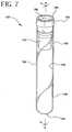
- FIGS. 7-13represent an alternative embodiment of the present invention.
- the alternative embodimentcomprises assembly 120 , which comprises a tube 130 , a closure 150 and a separator 170 .
- Tube 130has an open end 132 that includes a top edge 133 , a closed end 134 and a sidewall 136 extending between the open end and the closed end.
- Sidewall 136has an outer surface 138 and an inner surface 140 .
- Tube 130defines a receptacle with a central axis "A".
- Tube 130is preferably made from a substantially transparent and rigid material. Suitable materials or the tube include glass, polystyrene, polyethyleneterephthalate, polycarbonate and the like.
- Closure 150is disposed to fit over open end 132 of tube 130 .
- Closure 150comprises an annular upper portion 152 which extends over top edge 133 of sidewall 136 and a lower annular portion or skirt 154 of lesser diameter than the annular upper portion 152 which extends into and forms an interference fit with inner surface 140 of sidewall 136 for maintaining stopper 150 in place in open end 132 .
- Annular upper portion 152includes a top surface area 156 , sidewall 158 that converges from surface area 156 towards upper well area 160 .
- Well area 160is most preferably a thin diaphragm or a self sealing septum for directing and receiving the point of a needle to be inserted into and through the stopper.
- Lower annular skirt portion 154defines a lower well 162 , an inner wall surface, 164 an outer wall surface 166 and a bottom surface 168 .
- Well area 160 and lower well area 162define a thin diaphragm or self-sealing septum through which a needle may be inserted.
- the self sealing septum materialallows penetration by a piercing element such as a needle and then reseals when the piercing element is withdrawn.
- annular ledge or abutment 157separates annular upper portion 152 and lower annular portion 154 .
- gripping means 169Located on bottom surface 168 of lower annular portion 154 are gripping means 169 that are used to initially align and hold the separator.
- the closuremaybe made of natural rubber elastomer, synthetic thermoplastic and thermoset elastomeric materials.
- the closureis made of a resilient elastomeric material whereby the septum is self-sealing.
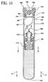
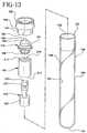
- separator 170comprises a bellow member 172 , a low-density buoyance or float member 190 and a high-density sinker or ballast member 210 .
- the components of the separatorare formed from materials to exhibit a combined density less than the density of red blood cells, but greater than the density of serum of a blood sample.
- Buoyancy member 190comprises a top section 211 a bottom section 212 and a central passageway 214 extending continuously between the ends.
- Bellow member 172comprises a rupturable elastomeric material such as Kraton® copolymer, a urethane or PVC.
- Bellow member 172includes a bottom 188, a top 186 , a seal body 191 extending between the top and bottom, an initially conically convex top wall 199 at top 186 .
- Ballast member 210comprises a cylindrical sidewall 220 extending from a top end 221 to a bottom end 222 and a central passageway 223 extending between the top and bottom ends.
- ballast member 210is fitted with bellow member 172 top end 221 of ballast member 210 is fitted within convex top wall 199 and then the bottom end of the ballast member is joined with top section 211 of the buoyance member whereby central passageway 223 extends from top wall 199 through to bottom end 222 of the ballast member 210 .
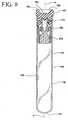
- a liquid sample Ais delivered to the tube by a needle that penetrates closure 150 in upper well area 160 and conical top wall 199 of bellow member 172 .
- the liquid sampleis blood.
- the liquid sampleis delivered into the passageway of the separator so that the liquid sample is introduced between closed end 34 of the tube and the separator whereby the outer surface of all components of the separator are substantially free of any contact with the fluid sample.
- seal bodydeflects, whereby the separator release from the closure and descends towards closed end 134 of tube 130 .
- a lower specific gravity fraction B of fluid sample Amoves upwardly past the separator.
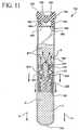
- seal body 191 of the separatordeflects reducing its diameter and eliminating its interference fit with the inner wall of the tube. This opens up a path 300 between the tube and the separator, permitting the flow of the low-density component of the fluid past the separator as the separator migrates down the tube.
- the low residual density component inside central passageway 223 of the separatorwill migrate downwardly and upwardly past the separator.
- separator 170serves as a divider between lower specific gravity portion B and higher specific gravity portion C of the liquid sample.
- Tube 130is compatible with most of the numerous additives used in sample collection tubes such as citrates, silicone, silicates, EDTA and the like that are used to condition the sample either to facilitate or retard clotting, or to preserve the sample for a particular analysis. It is within the purview of this invention that one or more additives may be used in the present invention for particular applications.
- additivessuch as citrates, silicone, silicates, EDTA and the like that are used to condition the sample either to facilitate or retard clotting, or to preserve the sample for a particular analysis. It is within the purview of this invention that one or more additives may be used in the present invention for particular applications.
- An assembly of the present inventionwas compared to a commercially available product that uses a gel as the separator mechanism. Ten samples of the present invention and ten samples of the commercial product were used.
- the commercial productwas VACUTAINER Brand PLUS SST® tubes (trademarks of and manufactured by Becton Dickinson and Co.. Franklin Lakes, NJ) (Catalog No. 367988).
- the separator of the present inventioncomprising a bellows, a float, and a ballast were made from separate molds using an injection molding process.
- the bellowswas made from a GLS Dynaflex® G6725 thermoplastic elastomer compound (DYNAFLEX® is a trademark of and manufactured by GLS Corporation, Cary, Illinois) having a specific gravity of 0.889.
- the floatwas made from a pre-compounded blend of Eastman LDPE 1870-A and 3M Scotchlite TM glass bubbles S60 (SCOTCHLITETM is a trademark of and manufactured by 3M, St. Paul, MN) to yield a specific gravity of about 0.809.
- the ballastwas made from Eastar® MN058 copolyester (EASTAR® is a trademark of and manufactured by Eastman Chemical Company, Kingsport, TN) with a specific gravity of about 1.335.
- the separatorwas assembled with a closure designed to receive the separator and then with a tube.
- the assemblywas assembled and evacuated to a level which yield 8.5 ml blood draw.
- a blood samplewas directed into each of the ten samples of the present invention and the commercial product. Each sample was placed in a floor model centrifuge and centrifuged at 1000 RCF for five minutes. The separator of the present invention and that of the commercial product migrated into position and formed a seal between the serum and the red blood cells/clot. The serum analytes were then measured and reported in Table 1. In clinical chemistry, analytes (components in human blood) are measured and used to aid in the diagnosis and monitoring of diseased states in human patients. The results of Table 1 show that the present invention, which has a non-gel separator, yields comparable serum analyte values as to the commercial product that contains a gel as the separator.
- the separator of the present inventioncomprising a bellows, a float, and a ballast, were made from separate molds using an injection molding process.
- the bellowswas made from GLS Dynaflex® G6725 thermoplastic elastomer compound (DYNAFLEX® is a trademark of and manufactured by GLS Corp., Gary, Ill) having a specific gravity of 0.889.
- the floatwas made from a pre-compounded blend of Dow LDPE 993I and Uniroyal Chemical Celogen® 754A to yield a specific gravity of 0.782.
- the ballastwas made from Eastar® MN058 copolyester (ESTAR® is a trademark of and manufactured by Eastman Chemical Company, Kingsport, TN) with a specific gravity of 1.335.
- ESTAR®is a trademark of and manufactured by Eastman Chemical Company, Kingsport, TN
- the separatorwas assembled with a closure designed to receive the separator and then with a tube. The assembly was assembled and evacuated to a level
- a blood samplewas directed into each sample. Then each sample was placed in a floor model centrifuge and centrifuged for three minutes. The separator of the present invention and that of the commercial product migrated into position and formed a seal between the serum and the red blood cells/clot. The serum analytes were then measured and reported in Table 2.
- An assembly of the present inventionwas compared to a commercially available product that has a gel component as the separator mechanism.
- a sample of the present invention and a sample of the commercial productwere used.
- the commercial productwas VACUTAINER Brand PLUS SST® tubes (trademarks of a manufactured by Becton Dickinson and Co., Franklin Lakes, NJ, Catalog No. 367988).
- the separator of the present inventioncomprising a bellows, a float, and a ballast, were made from separate molds using an injection molding process.
- the bellowswas made from GLS Dynaflex® G6730 thermoplastic elastomer compound (DYNAFLEX® is a trademark of an manufactured by GLS Corp., Gary, Ill) having a specific gravity of 0.889.
- the floatwas made from a pre-compounded blend of Dow LDPE 993I and Uniroyal Chemical Celogen® 754A to yield a specific gravity of 0.782.
- the ballastwas made from pigmented Eastar® MN058 copolyester (EASTAR® is a trademark of and manufactured by Eastman Chemical Co., Kingsport, TN) with a specific gravity of 1.335.
- EASTAR®is a trademark of and manufactured by Eastman Chemical Co., Kingsport, TN
- the separatorwas positioned at the bottom of the tube.
- a blood samplewas directed into each of the samples of the present invention and the commercial product. Then each sample was placed in a floor model centrifuge and centrifugal for ten minutes. The separator of the present invention and that of the commercial product migrates into position and forms a seal between the plasma and the red blood cells. The plasma analytes were measured and reported in Table 3.
Landscapes
- Health & Medical Sciences (AREA)
- Life Sciences & Earth Sciences (AREA)
- Chemical & Material Sciences (AREA)
- Engineering & Computer Science (AREA)
- Hematology (AREA)
- Biomedical Technology (AREA)
- General Health & Medical Sciences (AREA)
- Physics & Mathematics (AREA)
- Analytical Chemistry (AREA)
- Medicinal Chemistry (AREA)
- General Physics & Mathematics (AREA)
- Food Science & Technology (AREA)
- Molecular Biology (AREA)
- Biophysics (AREA)
- Biochemistry (AREA)
- Ecology (AREA)
- Urology & Nephrology (AREA)
- Immunology (AREA)
- Pathology (AREA)
- Clinical Laboratory Science (AREA)
- Chemical Kinetics & Catalysis (AREA)
- Centrifugal Separators (AREA)
- Investigating Or Analysing Biological Materials (AREA)
- Sampling And Sample Adjustment (AREA)
- Devices For Use In Laboratory Experiments (AREA)
Abstract
Description
- This invention relates to a device and method for separating heavier and lighter fractions of a fluid sample. More particularly, this invention relates to a device and method for collecting and transporting fluid samples whereby the device and fluid sample are subjected to centrifugation in order to cause separation of the heavier fraction from the lighter fraction of the fluid sample.
- Diagnostic tests may require separation of a patient's whole blood sample into components, such as serum or plasma, the lighter phase component, and red blood cells, the heavier phase component. Samples of whole blood are typically collected by venipuncture through a cannula or needle attached to a syringe or an evacuated collection tube. Separation of the blood into serum or plasma and red blood cells is then accomplished by rotation of the syringe or tube in a centrifuge. Such arrangements use a barrier for moving into an area adjacent the two phases of the sample being separated to maintain the components separated for subsequent examination of the individual components.
- A variety of devices have been used in collection devices to divide the area between the heavier and lighter phases of a fluid sample.
- The most widely used device includes thixotropic gel materials such as polyester gels in a tube. The present polyester gel serum separation tubes require special manufacturing equipment to prepare the gel and to fill the tubes. Moreover, the shelf-life of the product is limited in that overtime globules may be released from the gel mass. These globules have a specific gravity that is less than the separated serum and may float in the serum and may clog the measuring instruments, such as the instrument probes used during the clinical examination of the sample collected in the tube. Such clogging can lead to considerable downtime for the instrument to remove the clog.
- No commercially available gel is completely chemically inert to all analytes. If certain drugs are present in the blood sample when it is taken, there can be an adverse chemical reaction with the gel interface.
- The first part of claim 1 starts from an assembly for separating a fluid sample into a higher specific gravity phase and a lower specific gravity phase, as disclosed in US-A-3,894,950. The device disclosed therein comprises a separator element provided in a cylindrical tube and having external ribs for contacting the wall of the tubes. The separator element has a rigid core from metal, and a pathway extends vertically through the separator element. On top of the separator element a stretchable filter diaphragm is provided which acts as a pressure responsive valve-like filter element.
- Therefore, a need exists for a separator device that (i) is easily used to separate a blood sample; (ii) is independent of temperature during storage and shipping; (iii) is stable to radiation sterilization; (iv) employs the benefits of a thixotropic gel barrier yet avoids the many disadvantages of placing a gel in contact with the separated blood components; (v) minimizes cross contamination of the heavier and lighter phases of the sample during centrifugation; (vi) minimizes adhesion of the lower and higher density materials against the separator device; (vii) is able to move into position to form a barrier in less time than conventional methods and devices; (viii) is able to provide a clearer specimen with less cell contamination than conventional methods and devices; and (ix) can be used with standard sampling equipment.
- It is an object of the invention to provide an assembly for separating a fluid sample which fulfils the above-mentioned requirements.
- The assembly of the present invention is defined by claim 1. Accordingly, the float is mounted to the upper end of the bellows and the ballast is mounted to the lower end of the bellows.
- The invention refers further to a method of using the assembly.
- Most preferably, the container is a tube and the composite element is a separator arranged to move in the tube under the action of centrifugal force in order to separate the portions of a fluid sample.
- Most preferably, the tube comprises an open end, a closed end and a sidewall extending between the open end and closed end. The sidewall comprises an outer surface and an inner surface. The tube further comprises a closure disposed to fit in the open end of the tube with a resealable septum. Alternatively, both ends of the tube may be open, and both ends of the tube may be sealed by elastomeric closures. At least one of the closures of the tube may include a resealable septum.
- Preferably, the separator element is releasably positioned at the open end of the tube with the closure. Alternatively, the separator element may also be releasably positioned at the closed end of the tube.
- Preferably, the closure may further include a bottom recess that extends into the tube having a plurality of inwardly extending circumferentially spaced flexible walls or a flexible full ring for holding the separator.
- Preferably, the separator element comprises an overall specific gravity at a target specific gravity of σ1. The target specific gravity is that required to separate a fluid sample into at least two phases.
- Preferably, the separator comprises at least two or more regions of differing specific gravities. Preferably, at least one of the regions is higher than the target specific gravity and at least one of the regions is lower than the target specific gravity.
- Preferably, the separator element comprises a toroid or a bellows, a foam or a float and a sinker or a ballast. The bellows comprises opposed first and second ends and a seal body extending between the ends. The outer diameter of the seal body is larger than the inner diameter of the tube for sealing engagement. Most preferably, the seal body has elastic properties.
- Most preferably the float is securely mounted to the first end of the bellows and the ballast is securely mounted to the second end of the bellows.
- Alternatively, the bellows comprises a first end that is a resealable septum and an open second end.
- Preferably, the separator may be initially located at any position within the tube. Most preferably, the separator is held in position at the top of the tube by an interference fit between the seal body and the tube inner diameter.
- Preferably, the separator has central passageway that extends from the first end through the seal body and to the second end of the bellows.
- Preferably, the bellows has a specific gravity of about 0.8 to about 1.2. Most preferably, the bellows is made from an elastomer which has a 50% tensile modulus (YOUNGS) from about 7 kg/m2 (100 psi) to about 35 kg/cm2 (500 psi).
- Desirably, the seal body may be comprised of any natural or synthetic elastomer or mixture thereof, that are inert to the fluid sample of interest and is flexible.
- Preferably, the seal body comprises a qualitative stiffness, expressed as follows:

- Desirably, the qualitative stiffness of the seal body is from about 0.00006 to about 190.
- Preferably, the seal body may be subjected to a characteristic or radial deflection under an applied load, such as an axially applied load. The characteristic or radial deflection is defined as a change in length of the seal body relative to the change in cross section diameter of the seal body. Preferably, the seal body has a characteristic or radial deflection ratio of about 1.5 to about 3.5.
- Preferably, the seal body when subjected to an applied load, such as centrifugation, to cause axial deformation of the seal body, the change in cross section diameter may be expressed as follows:

wherein ΔDm is from about 5% to about 20%. - Therefore, a change in cross section diameter of the seal body is proportional to the undeflected cross section diameter of the seal body. Preferably, the proportion is from about .03 to about .20.
- Desirably, the ballast is a substantially rigid moldable thermoplastic material such as polyvinyl chloride, polystyrene, polyethylene, polypropylene, polyethyleneterethalate, stainless steel, polyester and mixtures thereof that are inert to the fluid sample of interest. Most preferably, the ballast is a high density material. Preferably, the ballast is mounted around the second end of the bellows so as not to interfere with the central passageway of the separator. Most preferably, the ballast has a useful specific gravity from about 1.1 to about 7.9.
- Desirably, the float is attached to the first end of the bellows whereby the float is in direct communication with the central passageway. Preferably, the float comprises small holes to bleed the air out of the central passageway of the separator. Most preferably, the float has a density from about .06 to about .95. Preferably, the float is a low density material such as polyethylene, polypropylene, polystyrene, foam, an air encapsulated system or a mixture of materials that reseal.
- Preferably, the separator has an aggregate specific gravity of about 1.028 to about 1.09 g/cc so that the separator will come to rest under centrifugal force substantially at the border between the heavier and lighter phases of a fluid sample under consideration.
- Preferably, the separator as a whole will function under load created by an applied acceleration from about 300g to about 3000g.
- Preferably, the separator is initially secured to the top area of the tube and in alignment with the closure. The separator is fitted at the top end of the tube whereby the bellows of the separator, which provides the largest diameter of the separator in its undeformed state, may have an interference fit with the inner surface of the sidewall of the tube.
- In use, a fluid sample enters the assembly by needle. The needle penetrates the closure and the float of the separator. The sample enters the assembly through the needle and through the central passageway of the bellows and then into the body of the tube. The needle is withdrawn from the assembly and the septum of the closure and the float reseals.
- The assembly is then subjected to centrifugation. Forces exerted by the centrifuge cause the seal body to separate from the inner wall of the tube whereby the seal body elongates due to the difference in the buoyancy of the different elements of the separator. Under centrifugation, the separator migrates axially down the tube towards the closed end to the desired interface.
- Sufficient movement of the separator will cause the separator to contact the blood. The ballast at the second end of the bellows moves axially downward under the centrifugal loading. The optional air bleed holes in the float or the resealable septum of the bellows serve to control the descent rate of the separator into the fluid sample.
- Following immersion of the separator in the fluid, the float provides a buoyant upward force on the separator due to the displaced fluid. Simultaneously, the ballast provides an axial force downward on the separator. The combined forces stretch the seal body axially causing radial movement of the seal body inwardly which pulls it out of contact with the inner wall of the tube so that it is free to move axially without any frictional drag.
- Therefore, a path is developed between the inner wall of the tube and the separator that permits the flow of the low-density component past the separator as it migrates down the tube. Migration of the separator terminates when it reaches the position between the lower density fluid component and higher density fluid or cellular/solid components, equal to its overall density. Upon terminating centrifugation, the seal body expands to its undeformed shape, sealing against the inner wall of the tube, thereby creating a barrier between the higher and lower density components of the sample fluid.
- The separator's position at the top of the tube in alignment with the closure and the separator's float and central passageway, provides easy direct loading of the fluid sample into the tube. Thus, the fluid sample is easily delivered into the tube without exposing the uncentrifuged fluid sample to the outer surface area of the separator.
- When the fluid sample is blood, the higher specific gravity portion that contains the cellular components is between the separator and the bottom of the tube after centrifugation. The lower specific gravity portion that contains the cell free serum or plasma fraction is between the float of the separator and the top of the tube.
- The separator of the present invention comprises a useful range of parameters and there are two principle driving equations for defining the parameters:


- The following non-dimensional parameters may then be substitute into the force balance:


- σt, σf, σs are the specific gravities of the bellows, float and ballast, respectively;
- Vt, Vf, Vs are the volumes of the bellows, float and ballast, respectively;
- ρw is the density of water;
- k is the separator spring constant;
- a is the applied acceleration; and
- δ is the deflection ration defined by: ΔL/ΔD, where ΔL is the change in length.
- The left side of the equation can be an infinite number of combinations of materials and geometries and if it is equal to the product of the right side it can be concluded that the device will function.
- Desirable values for the right side of the equation are as follows:
- δ = 1.5 - 3.5
- ΔD/D = .05 to .2
- S* = 0.043 to 0.220.
- Alternatively, the separator element may comprise an arrangement comprising a bellow member, a ballast member and a buoyancy or a float member.
- Most preferably, the bellow member is made of a material and shape which allows deflections caused by opposing forces.
- Most preferably, the buoyancy member has a component density whereby it has the capability of floating in serum of a blood sample. Preferably, the buoyancy member is made of a low density material such as foam or a material or mixture of materials so that it simulates a low density material such as foam.
- Most preferably, the ballast member has a component density whereby it has the capability of sinking in a blood sample. Preferably, the ballast member is made of a high density material such as a substantially rigid moldable thermoplastic material. Such materials include but are not limited to polyvinyl chloride, polystyrene, polyethylene, polypropylene, stainless steel, polyester and mixtures thereof that are inert to the fluid sample of interest.
- Most preferably, the separator element is arranged whereby the ballast member and buoyance members are connected and a central passageway extends through them. The bellow member covers the entrance to the central passageway and provides a pierceable barrier extending across the entrance to the central passageway.
- Most preferably, the separator elements are assembled to create opposing forces to deflect the bellow member inwardly and allow it to move axially in the tube while under the proper loading.
- Most preferably, the overall density of the separator is the target density σt whereby to cause the device to position itself between the higher and lower density of a fluid sample.
- Desirably, the bellow member may be comprised of any natural or synthetic elastomer or mixture thereof, that are inert to the fluid sample of interest and is flexible.
- Preferably, the bellow member comprises a qualitative stiffness, expressed as follows:

- Desirably, the qualitative stiffness of the bellow member is from about 0.00006 to about 190.
- Preferably, the bellow member may be subjected to a characteristic or radial deflection under an applied load, such as an axially applied load. The characteristic or radial deflection is defined as a change in length of the bellow member relative to the change in cross section diameter of the bellow member. Preferably, the bellow member has a characteristic or radial deflection ratio of about 1.5 to about 3.5.
- Preferably, the bellow member when subjected to an applied load, such as centrifugation, to cause axial deformation, the change in cross section diameter may be expressed as follows:

wherein ΔDm is from about 5% to about 20%. - Therefore, a change in cross section diameter of the bellow member is proportional to the undeflected cross section diameter of the bellow member. Preferably, the proportion is from about .03 to about .20.
- Desirably, the ballast member is a substantially rigid moldable thermoplastic material such as polyvinyl chloride, polystyrene, polyethylene, polypropylene, polyester and mixtures thereof that are inert to the fluid sample of interest. Most preferably, the ballast member is a high density material. Most preferably, the ballast member has a useful specific gravity from about 1.1 to about 7.9.
- Desirably, the buoyancy member has a useful specific gravity from about .06 to about .95. Preferably, the buoyancy member is a low density material such as foam or encapsulated air.
- Preferably, the separator has an aggregate specific gravity of about 1.028 to about 1.09 g/cc so that the separator will come to rest under centrifugal force substantially at the border between the heavier and lighter phases of a fluid sample under consideration.
- Preferably, the separator as a whole will function under load created by an applied acceleration from about 300g to about 3000g.
- Preferably, the separator is initially secured to the bottom recess of the closure. The separator is fitted with the closure whereby the bellows member of separator, which provides the largest diameter of the separator in its undeformed state, has a fit with the bottom recess of the closure. Alternatively, the separator may also be releasably positioned at the closed end of the tube.
- In use, a fluid sample enters the assembly by needle. The needle penetrates the closure and the bellow member of the separator. The sample enters the assembly through the needle and through the central passageway of the separator and then into the body of the tube. The needle is withdrawn from the assembly and the septum of the closure and the bellow member reseals.
- The assembly is then subjected to centrifugation. Forces exerted on the separator by the centrifuge cause the separator to separate from the closure or move from its initial position whereby the bellow member elongates as the separator migrates due to the forces pulling on it. Under centrifugation, the separator is released from the closure. The separator migrates axially down the tube towards the closed end.
- Sufficient movement of the separator will cause the separator to contact the blood. Air trapped in the central passageway creates a buoyancy that could prevent further sinking of the separator into the fluid. However, the trapped air vents through a defect in the bellow member that is caused by the needle. This venting of air permits further movement of the separator into the fluid.
- Following immersion of the separator in the fluid, the buoyancy member provides a buoyant upward force on the separator due to the displaced fluid. Simultaneously, the ballast member provides an axial force downward on the separator. The combined forces stretch the bellow member axially and pulls it out of contact with the closure so that it is free to move axially without any frictional drag.
- Therefore, a path is developed between the inner wall of the tube and the separator that permits the flow of the low-density component past the separator as it migrates down the tube. Migration of the separator terminates when it reaches the position between the lower density fluid component and higher density fluid or cellular/solid components, equal to its overall density. Upon terminating centrifugation, the bellow member expands to its undeformed shape, sealing against the inner wall of the tube, thereby creating a barrier between the higher and lower density components of the sample fluid.
- The separator's position at the top of the tube in alignment with the closure and the separator's penetrable bellows member and central passage, provides easy direct loading of the fluid sample into the tube. Thus, the fluid sample is easily delivered into the tube without exposing the uncentrifuged fluid sample to the outer surface area of the separator.
- When the fluid sample is blood, the higher specific gravity portion that contains the cellular components is between the separator and the bottom of the tube after centrifugation. The lower specific gravity portion that contains the cell free serum or plasma fraction is between the bellows of the separator and the top of the tube.
- The separator of the present invention comprises a useful range of parameters and there are two principle driving equations for defining the parameters:


- The following non-dimensional parameters may then be substitute into the force balance:


- σt, σf, σs are the specific gravities of the bellow member, buoyance member and ballast member, respectively;
- Vt, Vf, Vs are the volumes of the bellow member, buoyance member and ballast member, respectively;
- ρw is the density of water;
- k is the separator spring constant;
- a is the applied acceleration; and
- δ is the deflection ration defined by: ΔL/ΔD, where ΔL is the change in length.
- The left side of the equation can be an infinite number of combinations of materials and geometries and if it is equal to the product of the right side it can be concluded that the device will function.
- Desirable values for the right side of the equation are as follows:
- δ = 1.5 - 3.5
- ΔD/D = .05 to .2
- S* = 0.043 to 0.220.
- The assembly of the present invention is advantageous over existing separation products that use gel. In particular the assembly of the present invention will not interfere with analytes as compared to gels that may interfere with analytes. Another attribute of the present invention is that the assembly of the present invention will not interfere with therapeutic drug monitoring analytes.
- Most notably, is that the time to separate a fluid sample into separate densities is achieved in substantially less time with the assembly of the present invention as compared to assemblies that use gel.
- Another notable advantage of the present invention is that fluid specimens are not subjected to low density gel residuals that are at times available in products that use gel.
- A further attribute of the present invention is that there is no interference with instrument probes.
- Another attribute of the present invention is that samples for blood banking tests are more acceptable than when a gel separator is used.
- Another attribute of the present invention is that only the substantially cell-free serum fraction of a blood sample is exposed to the top surface of the separator, thus providing practitioners with a clean sample.
- Additionally, the assembly of the present invention does not require any additional steps or treatment by a medical practitioner, whereby a blood or fluid sample is drawn in the standard fashion, using standard sampling equipment.
- FIG. 1 is a perspective view of the assembly of the present invention.
- FIG. 2 is a longitudinal sectional view of the assembly of FIG. 1 taken along line 2-2 thereof.
- FIG. 3 is a longitudinal sectional view of the assembly of FIG. 1 taken along line 2-2 thereof illustrating fluid delivery into the assembly by a needle.
- FIG. 4 illustrates that assembly under centrifugation and the release of the separator from the gripping means of the closure.
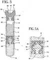
- FIGS. 5 and 5A illustrates the assembly after centrifugation and the separation of the liquid sample into higher and lower specific gravities.
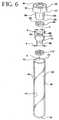
- FIG. 6 is a perspective view of the unassembled elements of the assembly of the present invention.
- FIG. 7 is a perspective view of an alternate embodiment of the assembly of the present invention.
- FIG. 8 is a longitudinal sectional view of the assembly of FIG. 7 taken along line 8-8 thereof.
- FIG. 9 is a longitudinal sectional view of the assembly of FIG. 7 taken along line 8-8 thereof illustrating fluid delivery into the assembly by a needle.
- FIG. 10 and 11 illustrates that assembly under centrifugation and the release of the separator from the gripping means of the closure.
- FIG. 12 illustrates the assembly after centrifugation and the separation of the liquid sample into higher and lower specific gravities.
- FIG. 13 is a perspective view of the unassembled elements of the assembly of the present invention.
- The present invention may be embodied in other specific forms and is not limited to any specific embodiments described in detail, which are merely exemplary. Various other modifications will be apparent to and readily made by those skilled in the art without departing from the scope of the invention. The scope of the invention is defined by the appended claims and their equivalents.
- One embodiment of the present invention is illustrated in FIGS. 1 to 6, wherein
assembly 20 comprises atube 30, aclosure 50 and aseparator 70. Tube 30 has anopen end 32 that includes atop edge 33, aclosed end 34 and asidewall 36 extending between the open end and the closed end.Sidewall 36 has anouter surface 38 and aninner surface 40.Tube 30 defines a receptacle with a central axis "A".Tube 30 is preferably made from a substantially transparent and rigid material. Suitable materials or the tube include glass, polystyrene, polyethyleneterephthalate, polycarbonate and the like.Closure 50 is disposed to fit overopen end 32 oftube 30.Closure 50 comprises an annularupper portion 52 which extends overtop edge 33 ofsidewall 36 and a lower annular portion orskirt 54 of lesser diameter than the annularupper portion 52 which extends into and forms an interference fit withinner surface 40 ofsidewall 36 for maintainingstopper 50 in place inopen end 32.- Annular
upper portion 52 includes atop surface area 56,sidewall 58 that converges fromsurface area 56 towardsupper well area 60. Wellarea 60 is most preferably a thin diaphragm or a self sealing septum for directing and receiving the point of a needle to be inserted into and through the stopper. - Lower
annular skirt portion 54 defines alower well 62, an inner wall surface,64 anouter wall surface 66 and abottom surface 68. Wellarea 60 andlower well area 62 define a thin diaphragm or self-sealing septum through which a needle may be inserted. The self sealing septum material allows penetration by a piercing element such as a needle and then reseals when the piercing element is withdrawn. - An annular ledge or
abutment 57 separates annularupper portion 52 and lowerannular portion 54. - Preferably, the closure maybe made of natural rubber elastomer, synthetic thermoplastic and thermoset elastomeric materials. Preferably, the closure is made of a resilient elastomeric material whereby the septum is self-sealing.
- As shown in FIG. 6,
separator 70 comprises an elastic toroid or an elastic bellows72, a low-density foam or alow density float 90 and a high-density sinker or ahigh density ballast 110. The components of the separator are formed from materials to exhibit a combined density less than the density of red blood cells, but greater than the density of serum of a blood sample. Bellows 72 includes atop section 86, abottom section 88, and aseal body 91 extending from the top section to the bottom section with acentral passageway 98 extending between the ends and the seal body.- Low-
density float 90 is located attop section 86 andballast 110 is located atbottom section 88.Ballast 110 surroundsbottom section 88 without obstructingcentral passageway 98.Low density float 90 is attop section 86 and in direct alignment withcentral passageway 98. - Low-
density float 90 comprisessmall holes 95 to bleed air out ofcentral passageway 98 when in use. - The outside diameter "a" of
top section 86 and the outside diameter "b" ofbottom section 88 is less than the outside diameter "c" of the seal body when the seal body is in its undeformed position. Seal body 91 ofbellows 72 and the inner wall of the tube form an interference fit. The low-density float and the high-density ballast do not interfere with the inner wall of the tube.- Bellows72 may be assembled by mounting
float 90 overtop section 86 andballast 110 around the outer circumference ofbottom end 88. The separator is then inserted into the open end of the tube. Sufficient radial interference causes the seal body to sealingly engage the inner tube sidewall. - As shown in FIG. 3, a liquid sampleA is delivered to the tube by a needle that penetrates
closure 50 inupper well area 60 and the float. For purposes of illustration only, the liquid sample is blood. The liquid sample is delivered into the passageway of the separator so that the liquid sample is introduced betweenclosed end 34 of the tube and the separator whereby the outer surface of all components of the separator are substantially free of any contact with the fluid sample. - As shown in FIG. 4 when
assembly 20 is subjected to centrifugation or axial centrifugation force, sealbody 91 ofseparator 70 deflects, releases from the inner wall of the tube and descends towardsclosed end 34 oftube 30. As the separator descends, a lower specific gravity fractionB of fluid sampleA moves upwardly past the separator. Air will be trapped in the passageway when the bottom section of the bellows contacts the fluid sample. This trapped air could restrict further downward movement of the separator. However, the small holes in the float defines a path through which trapped air may escape the passageway. Thus,separator 70 is permitted to sink into the fluid sample. - As the separator descends, seal
body 91 of the separator deflects reducing its diameter and eliminating its interference fit with the inner wall of the tube. This opens up apath 100 between the tube and the separator, permitting the flow of the low-density component of the fluid past the separator as the separator migrates down the tube. The low residual density component inside thepassageway 98 of the separator will migrate downwardly and upwardly past the separator. - As shown in FIGS. 5 and 5A, after centrifugation is terminated, the absence of the centrifugal load will cause tubular portion to resiliently return toward an underformed condition and tightly seal with the inner wall of the tube as shown in FIG. 5. Thus,
separator 70 serves as a divider between lower specific gravity portionB and higher specific gravity portion C of the liquid sample. Tube 30 is compatible with most of the numerous additives used in sample collection tubes such as citrates, silicone, silicates, EDTA and the like that are used to condition the sample either to facilitate or retard clotting, or to preserve the sample for a particular analysis. It is within the purview of this invention that one or more additives may be used in the present invention for particular applications.- FIGS. 7-13 represent an alternative embodiment of the present invention.
- As illustrated in FIGS. 7-13, the alternative embodiment comprises
assembly 120, which comprises atube 130, aclosure 150 and aseparator 170. Tube 130 has anopen end 132 that includes atop edge 133, aclosed end 134 and asidewall 136 extending between the open end and the closed end.Sidewall 136 has anouter surface 138 and aninner surface 140.Tube 130 defines a receptacle with a central axis "A".Tube 130 is preferably made from a substantially transparent and rigid material. Suitable materials or the tube include glass, polystyrene, polyethyleneterephthalate, polycarbonate and the like.Closure 150 is disposed to fit overopen end 132 oftube 130.Closure 150 comprises an annularupper portion 152 which extends overtop edge 133 ofsidewall 136 and a lower annular portion orskirt 154 of lesser diameter than the annularupper portion 152 which extends into and forms an interference fit withinner surface 140 ofsidewall 136 for maintainingstopper 150 in place inopen end 132.- Annular
upper portion 152 includes atop surface area 156,sidewall 158 that converges fromsurface area 156 towardsupper well area 160. Wellarea 160 is most preferably a thin diaphragm or a self sealing septum for directing and receiving the point of a needle to be inserted into and through the stopper. - Lower
annular skirt portion 154 defines alower well 162, an inner wall surface,164 anouter wall surface 166 and abottom surface 168. Wellarea 160 andlower well area 162 define a thin diaphragm or self-sealing septum through which a needle may be inserted. The self sealing septum material allows penetration by a piercing element such as a needle and then reseals when the piercing element is withdrawn. - An annular ledge or
abutment 157 separates annularupper portion 152 and lowerannular portion 154. Located onbottom surface 168 of lowerannular portion 154 are grippingmeans 169 that are used to initially align and hold the separator. - Preferably, the closure maybe made of natural rubber elastomer, synthetic thermoplastic and thermoset elastomeric materials. Preferably, the closure is made of a resilient elastomeric material whereby the septum is self-sealing.
- As shown in FIGS. 12 and 13,
separator 170 comprises abellow member 172, a low-density buoyance orfloat member 190 and a high-density sinker orballast member 210. The components of the separator are formed from materials to exhibit a combined density less than the density of red blood cells, but greater than the density of serum of a blood sample. Buoyancy member 190 comprises a top section211 abottom section 212 and acentral passageway 214 extending continuously between the ends.Bellow member 172 comprises a rupturable elastomeric material such as Kraton® copolymer, a urethane or PVC.Bellow member 172 includes a bottom188, a top186, aseal body 191 extending between the top and bottom, an initially conically convextop wall 199 attop 186.Ballast member 210 comprises a cylindrical sidewall220 extending from atop end 221 to abottom end 222 and acentral passageway 223 extending between the top and bottom ends.- The separator is assembled whereby
ballast member 210 is fitted withbellow member 172top end 221 ofballast member 210 is fitted within convextop wall 199 and then the bottom end of the ballast member is joined withtop section 211 of the buoyance member wherebycentral passageway 223 extends fromtop wall 199 through tobottom end 222 of theballast member 210. - As shown in FIG.9, a liquid sample A is delivered to the tube by a needle that penetrates
closure 150 inupper well area 160 and conicaltop wall 199 ofbellow member 172. For purposes of illustration only, the liquid sample is blood. The liquid sample is delivered into the passageway of the separator so that the liquid sample is introduced betweenclosed end 34 of the tube and the separator whereby the outer surface of all components of the separator are substantially free of any contact with the fluid sample. - As shown in FIGS. 10 and 11 when
assembly 120 is subjected to centrifugation or axial centrifugation force, seal body deflects, whereby the separator release from the closure and descends towardsclosed end 134 oftube 130. As the separator descends, a lower specific gravity fractionB of fluid sampleA moves upwardly past the separator. - As the separator descends,
seal body 191 of the separator deflects reducing its diameter and eliminating its interference fit with the inner wall of the tube. This opens up apath 300 between the tube and the separator, permitting the flow of the low-density component of the fluid past the separator as the separator migrates down the tube. The low residual density component insidecentral passageway 223 of the separator will migrate downwardly and upwardly past the separator. - After centrifugation is terminated, the absence of the centrifugal load will cause the seal body to resiliently return toward an undeformed condition and tightly seal with the inner wall of the tube as shown in FIG. 12. Thus,
separator 170 serves as a divider between lower specific gravity portionB and higher specific gravity portionC of the liquid sample. Tube 130 is compatible with most of the numerous additives used in sample collection tubes such as citrates, silicone, silicates, EDTA and the like that are used to condition the sample either to facilitate or retard clotting, or to preserve the sample for a particular analysis. It is within the purview of this invention that one or more additives may be used in the present invention for particular applications.- An assembly of the present invention was compared to a commercially available product that uses a gel as the separator mechanism. Ten samples of the present invention and ten samples of the commercial product were used. The commercial product was VACUTAINER Brand PLUS SST® tubes (trademarks of and manufactured by Becton Dickinson and Co.. Franklin Lakes, NJ) (Catalog No. 367988).
- The separator of the present invention comprising a bellows, a float, and a ballast were made from separate molds using an injection molding process. The bellows was made from a GLS Dynaflex® G6725 thermoplastic elastomer compound (DYNAFLEX® is a trademark of and manufactured by GLS Corporation, Cary, Illinois) having a specific gravity of 0.889. The float was made from a pre-compounded blend of Eastman LDPE 1870-A and 3M Scotchlite™ glass bubbles S60 (SCOTCHLITE™ is a trademark of and manufactured by 3M, St. Paul, MN) to yield a specific gravity of about 0.809. The ballast was made from Eastar® MN058 copolyester (EASTAR® is a trademark of and manufactured by Eastman Chemical Company, Kingsport, TN) with a specific gravity of about 1.335.
- The separator was assembled with a closure designed to receive the separator and then with a tube. The assembly was assembled and evacuated to a level which yield 8.5 ml blood draw.
- A blood sample was directed into each of the ten samples of the present invention and the commercial product. Each sample was placed in a floor model centrifuge and centrifuged at 1000 RCF for five minutes. The separator of the present invention and that of the commercial product migrated into position and formed a seal between the serum and the red blood cells/clot. The serum analytes were then measured and reported in Table 1. In clinical chemistry, analytes (components in human blood) are measured and used to aid in the diagnosis and monitoring of diseased states in human patients. The results of Table 1 show that the present invention, which has a non-gel separator, yields comparable serum analyte values as to the commercial product that contains a gel as the separator.

- The separator of the present invention comprising a bellows, a float, and a ballast, were made from separate molds using an injection molding process. The bellows was made from GLS Dynaflex® G6725 thermoplastic elastomer compound (DYNAFLEX® is a trademark of and manufactured by GLS Corp., Gary, Ill) having a specific gravity of 0.889. The float was made from a pre-compounded blend of Dow LDPE 993I and Uniroyal Chemical Celogen® 754A to yield a specific gravity of 0.782. The ballast was made from Eastar® MN058 copolyester (ESTAR® is a trademark of and manufactured by Eastman Chemical Company, Kingsport, TN) with a specific gravity of 1.335. The separator was assembled with a closure designed to receive the separator and then with a tube. The assembly was assembled and evacuated to a level which yield 8.5 ml blood draw.
- A blood sample was directed into each sample. Then each sample was placed in a floor model centrifuge and centrifuged for three minutes. The separator of the present invention and that of the commercial product migrated into position and formed a seal between the serum and the red blood cells/clot. The serum analytes were then measured and reported in Table 2.


- An assembly of the present invention was compared to a commercially available product that has a gel component as the separator mechanism. A sample of the present invention and a sample of the commercial product were used. The commercial product was VACUTAINER Brand PLUS SST® tubes (trademarks of a manufactured by Becton Dickinson and Co., Franklin Lakes, NJ, Catalog No. 367988). The separator of the present invention comprising a bellows, a float, and a ballast, were made from separate molds using an injection molding process. The bellows was made from GLS Dynaflex® G6730 thermoplastic elastomer compound (DYNAFLEX® is a trademark of an manufactured by GLS Corp., Gary, Ill) having a specific gravity of 0.889. The float was made from a pre-compounded blend of Dow LDPE 993I and Uniroyal Chemical Celogen® 754A to yield a specific gravity of 0.782. The ballast was made from pigmented Eastar® MN058 copolyester (EASTAR® is a trademark of and manufactured by Eastman Chemical Co., Kingsport, TN) with a specific gravity of 1.335. The separator was positioned at the bottom of the tube.
- A blood sample was directed into each of the samples of the present invention and the commercial product. Then each sample was placed in a floor model centrifuge and centrifugal for ten minutes. The separator of the present invention and that of the commercial product migrates into position and forms a seal between the plasma and the red blood cells. The plasma analytes were measured and reported in Table 3.
TABLE 3 Glucose BUN Creatinine Sodium Initial 24hrs Initial 24hrs Initial 24hrs Initial 24 hrs Present Invention Tube N=3 51 38 19 19 1.1 1.1 140 143 PLUS PST Tube N=1 49 29 19 20 1.1 1.2 142 142 Potassium Chloride Calcium Phosphorus, Inorganic Initial 24hrs Initial 24hrs Initial 24hrs Initial 24 hrs Present Invention Tube N=3 4.1 4.4 104 104 9.3 9.7 3.7 3.6 PLUS PST Tube N=1 4.0 4.2 104 104 9.5 9.6 3.9 3.9 Protein, Total Albumin Cholesterol Bilirubin, Total Initial 24hrs Initial 24hrs Initial 24hrs Initial 24 hrs Present Invention Tube N=3 7.8 7.8 4.6 4.7 176 179 1.0 0.8 PLUS PST Tube N=1 7.7 7.7 4.6 4.7 175 173 1.0 0.8 Alkaline Phosphatase LDH GGT AST Initial 24hrs Initial 24hrs Initial 24hrs Initial 24 hrs Present Invention Tube N=3 0.97 0.67 153 166 12 13 23 22 PLUS PST Tube N=1 1.0 0.8 149 170 13 13 23 22 ALT Uric Acid Iron, Total Triglycerides Initial 24hrs Initial 24hrs Initial 24hrs Initial 24 hrs Present Invention Tube N=3 17 18 3.8 4.1 351 352 82 87 PLUS PST Tube N=1 17 17 3.7 4.0 344 353 81 83


Claims (6)
- An assembly for separating a fluid sample into a higher specific gravity phase and a lower specific gravity phase comprising:a separator element (70;170) comprising a bellows (72;172), a float (90;190) and a ballast (110;210);said bellows(72; 172) comprising opposed first (86;186) and second ends (88;188), a seal body (91;191) extending between said ends and a central passageway (98;223) extending through said bellows;characterized in thatthe float (90;190) is mounted to said first end (86;186) of said bellows; andthe ballast (110;210) is mounted to said second end (88;188) of said bellows.
- An assembly according to claim 1, further comprising:a tube (30;130) comprising an open end (32;132), a closed end (34; 134), an inner diameter, an outer diameter and a sidewall (36;136) extending between said open end and said closed end;said sidewall (36;136) comprising an outer surface (38;138) and an inner surface (40; 140);a closure (50;150) disposed in said open end of said tube;said separator element movable axially in said tube under action of centrifugal force ;said separator element providing selectively an annular seal and an open passage there around in response to pressure differentials in said tube above and below said separator ;the seal body (91;191) extending between said ends for selectively providing an interference fit and an open passage with said inner surface (40;140) of said sidewall (36;136) of said tube in response to alternating equal and different pressures above and below said separator element (70;170) and the central passageway (98;223) extending through said bellows (72;172) to direct said fluid sample into said assembly
- An assembly according to claim 2, wherein the float (90;190) comprises a resealable septum.
- The assembly of one of claims 1-3, wherein the separator comprises:the separator element (170) comprising the bellow member (172), the ballast member (210) and a buoyancy member (190);said bellow member (172) comprising a bottom section, a top section, a seal body extending between said top section and said bottom section and an initially conically convex top wall at said top section;said buoyancy member (190) comprising a top section (211), a bottom section (212) and a central passageway (214) extending continuously between said top and bottom sections;said ballast member (210) comprising a top end (221), a bottom end (222), a sidewall (220) extending between said top end and said bottom end and a central passageway (223) surrounded by said sidewall extending between said top end and said bottom end; andwhereby said buoyancy member (190) is fitted within said convex top wall (186) of said bellow member (172) and said ballast member (210) is joined to surround said buoyancy member (190) whereby a central passageway (223) extends from said convex top wall (186) to said bottom end (222) of said ballast member (210).
- A method of using the assembly of claim 3, comprising the steps of:(a) providing the tube (30;130) comprising open end (32;132), closed end (34;134), inner diameter, outer diameter and sidewall (36;136) extending between said open end and said closed end and comprising outer surface (38;138) and inner surface (40; 140);(b) providing closure (50;150) disposed in said open end of said tube comprising resealable septum;(c) providing the separator element (70; 170) comprising the bellows, the float (90;190) and the ballast (110;210) whereby said bellows (72;172) comprises opposed first and second ends, the seal body (91;191) extending between said ends for selectively providing an interference fit and an open passage with said inner surface (40;140) of said sidewall of said tube in response to alternating equal and different pressures above and below said separator, and central passageway(98;223) extending through said bellows; said float (90;190) comprising said resealable septum is mounted to said first end of said bellows and said ballast (110;210) is mounted to said second end of said bellows;(d) providing said separator element (70;170) in said tube (30;130) whereby said seal body (91;191) comprises an interference fit with said inner surface (40;140);(e) providing a needle that penetrates said closure (50;150) and said float (90;190);(f) delivering a fluid sample to said tube (30;130) whereby said sample enters through said needle and through said central passageway (98;223) of said bellows and then into said body of said tube;(g) removing said needle from said assembly whereby each said septum of said closure (50; 150) and said float (90; 190) reseals;(h) subjecting said tube (30;130) with said separator element (70;170) to centrifugation whereby said seal body (91;191) separates from said inner wall of said tube and said separator migrates axially in said tube whereby the low density component of the sample migrates down the tube; and(i) terminating said centrifugation whereby said seal body (91;191) expands to its underformed shaping, sealing against said inner wall of said tube, thereby creating a barrier between said higher and lower density components of said fluid sample.
- The method of claim 5, wherein said bellows (172) has an initially conically convex top wall at its said top section.
Applications Claiming Priority (4)
| Application Number | Priority Date | Filing Date | Title |
|---|---|---|---|
| US11092898P | 1998-12-05 | 1998-12-05 | |
| US11093498P | 1998-12-05 | 1998-12-05 | |
| US110928P | 1998-12-05 | ||
| US110934P | 1998-12-05 |
Publications (3)
| Publication Number | Publication Date |
|---|---|
| EP1006360A2 EP1006360A2 (en) | 2000-06-07 |
| EP1006360A3 EP1006360A3 (en) | 2001-08-08 |
| EP1006360B1true EP1006360B1 (en) | 2006-05-31 |
Family
ID=26808517
Family Applications (1)
| Application Number | Title | Priority Date | Filing Date |
|---|---|---|---|
| EP99124305AExpired - LifetimeEP1006360B1 (en) | 1998-12-05 | 1999-12-06 | Device and method for separating components of a fluid sample |
Country Status (6)
| Country | Link |
|---|---|
| US (1) | US6479298B1 (en) |
| EP (1) | EP1006360B1 (en) |
| JP (1) | JP4306902B2 (en) |
| AT (1) | ATE328275T1 (en) |
| DE (1) | DE69931584T2 (en) |
| ES (1) | ES2260882T3 (en) |
Cited By (14)
| Publication number | Priority date | Publication date | Assignee | Title |
|---|---|---|---|---|
| US7780860B2 (en) | 2002-05-24 | 2010-08-24 | Biomet Biologics, Llc | Apparatus and method for separating and concentrating fluids containing multiple components |
| US7806276B2 (en) | 2007-04-12 | 2010-10-05 | Hanuman, Llc | Buoy suspension fractionation system |
| US7832566B2 (en) | 2002-05-24 | 2010-11-16 | Biomet Biologics, Llc | Method and apparatus for separating and concentrating a component from a multi-component material including macroparticles |
| US7837884B2 (en) | 2002-05-03 | 2010-11-23 | Hanuman, Llc | Methods and apparatus for isolating platelets from blood |
| US7845499B2 (en) | 2002-05-24 | 2010-12-07 | Biomet Biologics, Llc | Apparatus and method for separating and concentrating fluids containing multiple components |
| US7992725B2 (en) | 2002-05-03 | 2011-08-09 | Biomet Biologics, Llc | Buoy suspension fractionation system |
| US8313954B2 (en) | 2009-04-03 | 2012-11-20 | Biomet Biologics, Llc | All-in-one means of separating blood components |
| US8337711B2 (en) | 2008-02-29 | 2012-12-25 | Biomet Biologics, Llc | System and process for separating a material |
| US8394342B2 (en) | 2008-07-21 | 2013-03-12 | Becton, Dickinson And Company | Density phase separation device |
| US8747781B2 (en) | 2008-07-21 | 2014-06-10 | Becton, Dickinson And Company | Density phase separation device |
| US8794452B2 (en) | 2009-05-15 | 2014-08-05 | Becton, Dickinson And Company | Density phase separation device |
| US9283704B2 (en) | 2001-06-18 | 2016-03-15 | Becton, Dickinson And Company | Multilayer containers |
| US9333445B2 (en) | 2008-07-21 | 2016-05-10 | Becton, Dickinson And Company | Density phase separation device |
| US9694359B2 (en) | 2014-11-13 | 2017-07-04 | Becton, Dickinson And Company | Mechanical separator for a biological fluid |
Families Citing this family (58)
| Publication number | Priority date | Publication date | Assignee | Title |
|---|---|---|---|---|
| US6406671B1 (en)* | 1998-12-05 | 2002-06-18 | Becton, Dickinson And Company | Device and method for separating components of a fluid sample |
| US7001774B1 (en)* | 1999-03-05 | 2006-02-21 | Microliter Analytical Supplies, Inc. | Sample collection and processing device |
| US7947236B2 (en) | 1999-12-03 | 2011-05-24 | Becton, Dickinson And Company | Device for separating components of a fluid sample |
| US6803022B2 (en)* | 1999-12-06 | 2004-10-12 | Becton, Dickinson And Company | Device and method for separating components of a fluid sample |
| US6793892B1 (en) | 1999-12-06 | 2004-09-21 | Volker Niermann | Device and method for separating components of a fluid sample |
| AT500247B1 (en) | 2001-03-30 | 2007-06-15 | Greiner Bio One Gmbh | RECEIVING DEVICE, ESPECIALLY FOR BODY FLUIDS, WITH A SEPARATION DEVICE AND SEPARATING DEVICE THEREFOR |
| DE10149991A1 (en) | 2001-10-11 | 2003-04-30 | Vodafone Ag | Registration system for vehicles with GPS |
| US20060278588A1 (en) | 2002-05-24 | 2006-12-14 | Woodell-May Jennifer E | Apparatus and method for separating and concentrating fluids containing multiple components |
| ES2894356T3 (en)* | 2003-02-13 | 2022-02-14 | Becton Dickinson Co | Devices for the removal of components during blood collection and their uses |
| CN1307397C (en)* | 2003-05-23 | 2007-03-28 | 诺亚公司 | Flat closed heat pipe and its producing method |
| WO2005014173A1 (en)* | 2003-08-05 | 2005-02-17 | Becton, Dickinson And Company | Device and methods for collection of biological fluidsample and treatment of selected components |
| US7798021B2 (en)* | 2006-01-12 | 2010-09-21 | Gamble Kimberly R | Method and apparatus for sample processing and injection |
| US8567609B2 (en) | 2006-05-25 | 2013-10-29 | Biomet Biologics, Llc | Apparatus and method for separating and concentrating fluids containing multiple components |
| KR100790888B1 (en) | 2006-09-26 | 2008-01-02 | 삼성전자주식회사 | Centrifugal Force-based Fluid Injection Device for Microfluidic Chips |
| US8328024B2 (en) | 2007-04-12 | 2012-12-11 | Hanuman, Llc | Buoy suspension fractionation system |
| EP2259774B1 (en) | 2008-02-27 | 2012-12-12 | Biomet Biologics, LLC | Methods and compositions for delivering interleukin-1 receptor antagonist |
| KR100933151B1 (en) | 2008-05-09 | 2009-12-21 | 엄영록 | Teflon Sampling Vessel Using Gas Condensation by Air Cooling |
| WO2010020247A1 (en) | 2008-08-22 | 2010-02-25 | Reapplix Aps | Multilayered blood product |
| US20100093551A1 (en)* | 2008-10-09 | 2010-04-15 | Decision Biomarkers, Inc. | Liquid Transfer and Filter System |
| US8309343B2 (en) | 2008-12-01 | 2012-11-13 | Baxter International Inc. | Apparatus and method for processing biological material |
| EP2376232B1 (en)* | 2008-12-04 | 2017-03-22 | Thermogenesis Corp. | Apparatus and method for separating and isolating components of a biological fluid |
| US8187475B2 (en) | 2009-03-06 | 2012-05-29 | Biomet Biologics, Llc | Method and apparatus for producing autologous thrombin |
| US9011800B2 (en) | 2009-07-16 | 2015-04-21 | Biomet Biologics, Llc | Method and apparatus for separating biological materials |
| KR101069877B1 (en) | 2009-10-28 | 2011-10-05 | 임기표 | Kit of centrifuge separation and methods for centrifuging using the same |
| US10105706B2 (en) | 2010-01-19 | 2018-10-23 | Becton, Dickinson And Company | Container assembly and system for detection thereof |
| US8591391B2 (en) | 2010-04-12 | 2013-11-26 | Biomet Biologics, Llc | Method and apparatus for separating a material |
| US8377395B2 (en)* | 2010-04-29 | 2013-02-19 | Charles M. Coleman | Integrated blood specimen processor |
| JP5933914B2 (en)* | 2010-09-08 | 2016-06-15 | 真喜夫 浅地 | Elastic tube |
| CA2811777C (en)* | 2010-09-20 | 2015-08-11 | Reapplix Aps | Container for use when making a multi-layered blood product |
| JP2012239441A (en)* | 2011-05-23 | 2012-12-10 | Seiko Epson Corp | Reaction vessel |
| US9427707B2 (en) | 2012-08-10 | 2016-08-30 | Jean I. Montagu | Filtering blood |
| US9642956B2 (en) | 2012-08-27 | 2017-05-09 | Biomet Biologics, Llc | Apparatus and method for separating and concentrating fluids containing multiple components |
| WO2014039498A1 (en) | 2012-09-07 | 2014-03-13 | Becton, Dickinson And Company | Method and apparatus for microorganism detection |
| US9039999B2 (en) | 2012-11-30 | 2015-05-26 | Rarecyte, Inc. | Apparatus, system, and method for collecting a target material |
| EP2925853B1 (en)* | 2012-11-30 | 2019-07-24 | Rarecyte, Inc. | System for collecting a target material |
| US9539570B2 (en) | 2012-11-30 | 2017-01-10 | Rarecyte, Inc. | Apparatus, system, and method for collecting a target material |
| US9625360B2 (en)* | 2012-11-30 | 2017-04-18 | Rarecyte, Inc. | Apparatus, system, and method for collecting a target material |
| US9956555B2 (en) | 2012-11-30 | 2018-05-01 | Rarecyte, Inc. | Apparatus, system, and method for collecting a target material |
| US9895418B2 (en) | 2013-03-15 | 2018-02-20 | Biomet Biologics, Llc | Treatment of peripheral vascular disease using protein solutions |
| US9950035B2 (en) | 2013-03-15 | 2018-04-24 | Biomet Biologics, Llc | Methods and non-immunogenic compositions for treating inflammatory disorders |
| US20140271589A1 (en) | 2013-03-15 | 2014-09-18 | Biomet Biologics, Llc | Treatment of collagen defects using protein solutions |
| US10208095B2 (en) | 2013-03-15 | 2019-02-19 | Biomet Manufacturing, Llc | Methods for making cytokine compositions from tissues using non-centrifugal methods |
| US10143725B2 (en) | 2013-03-15 | 2018-12-04 | Biomet Biologics, Llc | Treatment of pain using protein solutions |
| JP5714063B2 (en)* | 2013-07-16 | 2015-05-07 | サーモジェネシス コーポレーション | Apparatus and method for separating and isolating body fluid components |
| CN105745318B (en)* | 2013-11-26 | 2018-06-12 | 瑞尔赛特股份有限公司 | For collecting the devices, systems, and methods of target substance |
| WO2015128769A1 (en)* | 2014-02-13 | 2015-09-03 | John Edgar Scragg | A separator for separating a heavier liquid from a lighter liquid |
| US20160136639A1 (en)* | 2014-11-13 | 2016-05-19 | Becton, Dickinson And Company | Mechanical Separator for a Biological Fluid |
| CN105342846A (en)* | 2015-12-18 | 2016-02-24 | 长沙汇一制药机械有限公司 | Cover for infusion bag and infusion bag |
| CN105380789A (en)* | 2015-12-18 | 2016-03-09 | 长沙汇一制药机械有限公司 | Cover used for infusion bag and provided with easy-to-break joints and infusion bag |
| DE102017108935B4 (en)* | 2017-04-26 | 2018-12-06 | Sarstedt Aktiengesellschaft & Co.Kg | Separator and tubular container with the separator |
| DE102017108937B4 (en) | 2017-04-26 | 2018-12-06 | Sarstedt Aktiengesellschaft & Co.Kg | separating body |
| DE102017108933B4 (en) | 2017-04-26 | 2018-12-06 | Sarstedt Aktiengesellschaft & Co.Kg | separating body |
| DE102017108940A1 (en)* | 2017-04-26 | 2018-10-31 | Sarstedt Aktiengesellschaft & Co.Kg | separating body |
| EP3658885A4 (en) | 2017-07-27 | 2021-09-22 | Biomerieux, Inc | INSULATING PIPE |
| KR102051207B1 (en) | 2018-01-30 | 2019-12-03 | 이준석 | Piston for centriguation |
| DE102019121723A1 (en) | 2019-08-13 | 2021-02-18 | Sarstedt Ag & Co. Kg | Separation bodies and methods for separating blood plasma and blood cells |
| CN111568442B (en)* | 2020-05-20 | 2022-05-31 | 江苏科华医疗器械科技有限公司 | Flexible stirring formula capillary plastics heparin tube |
| CN113941384B (en)* | 2021-11-21 | 2022-11-01 | 洛阳职业技术学院 | Capsule type secondary centrifuge tube capable of being applied to rapid nondestructive analysis |
Family Cites Families (18)
| Publication number | Priority date | Publication date | Assignee | Title |
|---|---|---|---|---|
| US3894950A (en) | 1974-02-27 | 1975-07-15 | Becton Dickinson Co | Serum separator improvement with stretchable filter diaphragm |
| US3891553A (en)* | 1974-02-27 | 1975-06-24 | Becton Dickinson Co | Serum and plasma separator {13 {0 constrictionless type |
| US3957654A (en)* | 1974-02-27 | 1976-05-18 | Becton, Dickinson And Company | Plasma separator with barrier to eject sealant |
| US3897343A (en)* | 1974-02-27 | 1975-07-29 | Becton Dickinson Co | Plasma separator-hydrostatic pressure type |
| US3890237A (en)* | 1974-02-27 | 1975-06-17 | Becton Dickinson Co | Plasma separator {13 {0 cord stop type |
| US3882021A (en)* | 1974-02-27 | 1975-05-06 | Becton Dickinson Co | Sealed assembly for separation of blood with anti-red cell barrier |
| US3909419A (en) | 1974-02-27 | 1975-09-30 | Becton Dickinson Co | Plasma separator with squeezed sealant |
| US3887466A (en)* | 1974-02-27 | 1975-06-03 | Becton Dickinson Co | Serum/plasma separator cannula fluid by-pass type centrifugal valve cannula seal |
| US3887464A (en)* | 1974-02-27 | 1975-06-03 | Becton Dickinson Co | Serum/plasma separator with centrifugal valve seal |
| CA1074273A (en) | 1976-05-06 | 1980-03-25 | Sherwood Medical Industries Inc. | Phase separation device |
| JPS5917386B2 (en)* | 1979-03-23 | 1984-04-20 | テルモ株式会社 | Blood separation method and device |
| US4315892A (en)* | 1980-07-18 | 1982-02-16 | Sherwood Medical Industries, Inc. | Fluid collection device having phase partitioning means |
| US4417981A (en) | 1981-05-04 | 1983-11-29 | Becton, Dickinson And Company | Blood phase separator device |
| SE448323B (en) | 1985-08-27 | 1987-02-09 | Ersson Nils Olof | PROCEDURE AND PROCEDURE TO SEPARATE SERUM OR PLASMA FROM BLOOD |
| US4818386A (en)* | 1987-10-08 | 1989-04-04 | Becton, Dickinson And Company | Device for separating the components of a liquid sample having higher and lower specific gravities |
| US5271852A (en)* | 1992-05-01 | 1993-12-21 | E. I. Du Pont De Nemours And Company | Centrifugal methods using a phase-separation tube |
| US5455009A (en) | 1993-09-14 | 1995-10-03 | Becton, Dickinson And Company | Blood collection assembly including clot-accelerating plastic insert |
| US5585007A (en) | 1994-12-07 | 1996-12-17 | Plasmaseal Corporation | Plasma concentrate and tissue sealant methods and apparatuses for making concentrated plasma and/or tissue sealant |
- 1999
- 1999-12-03USUS09/454,988patent/US6479298B1/ennot_activeExpired - Lifetime
- 1999-12-06ESES99124305Tpatent/ES2260882T3/ennot_activeExpired - Lifetime
- 1999-12-06DEDE69931584Tpatent/DE69931584T2/ennot_activeExpired - Lifetime
- 1999-12-06ATAT99124305Tpatent/ATE328275T1/enactive
- 1999-12-06JPJP34695099Apatent/JP4306902B2/ennot_activeExpired - Lifetime
- 1999-12-06EPEP99124305Apatent/EP1006360B1/ennot_activeExpired - Lifetime
Cited By (41)
| Publication number | Priority date | Publication date | Assignee | Title |
|---|---|---|---|---|
| US9283704B2 (en) | 2001-06-18 | 2016-03-15 | Becton, Dickinson And Company | Multilayer containers |
| US7992725B2 (en) | 2002-05-03 | 2011-08-09 | Biomet Biologics, Llc | Buoy suspension fractionation system |
| US7837884B2 (en) | 2002-05-03 | 2010-11-23 | Hanuman, Llc | Methods and apparatus for isolating platelets from blood |
| US8187477B2 (en) | 2002-05-03 | 2012-05-29 | Hanuman, Llc | Methods and apparatus for isolating platelets from blood |
| US7832566B2 (en) | 2002-05-24 | 2010-11-16 | Biomet Biologics, Llc | Method and apparatus for separating and concentrating a component from a multi-component material including macroparticles |
| US7845499B2 (en) | 2002-05-24 | 2010-12-07 | Biomet Biologics, Llc | Apparatus and method for separating and concentrating fluids containing multiple components |
| US7914689B2 (en) | 2002-05-24 | 2011-03-29 | Biomet Biologics, Llc | Apparatus and method for separating and concentrating fluids containing multiple components |
| US8808551B2 (en) | 2002-05-24 | 2014-08-19 | Biomet Biologics, Llc | Apparatus and method for separating and concentrating fluids containing multiple components |
| US8048321B2 (en) | 2002-05-24 | 2011-11-01 | Biomet Biologics, Llc | Apparatus and method for separating and concentrating fluids containing multiple components |
| US8062534B2 (en) | 2002-05-24 | 2011-11-22 | Biomet Biologics, Llc | Apparatus and method for separating and concentrating fluids containing multiple components |
| US7780860B2 (en) | 2002-05-24 | 2010-08-24 | Biomet Biologics, Llc | Apparatus and method for separating and concentrating fluids containing multiple components |
| US8119013B2 (en) | 2007-04-12 | 2012-02-21 | Hanuman, Llc | Method of separating a selected component from a multiple component material |
| US7806276B2 (en) | 2007-04-12 | 2010-10-05 | Hanuman, Llc | Buoy suspension fractionation system |
| US8337711B2 (en) | 2008-02-29 | 2012-12-25 | Biomet Biologics, Llc | System and process for separating a material |
| US9333445B2 (en) | 2008-07-21 | 2016-05-10 | Becton, Dickinson And Company | Density phase separation device |
| US9452427B2 (en) | 2008-07-21 | 2016-09-27 | Becton, Dickinson And Company | Density phase separation device |
| US8747781B2 (en) | 2008-07-21 | 2014-06-10 | Becton, Dickinson And Company | Density phase separation device |
| US9933344B2 (en) | 2008-07-21 | 2018-04-03 | Becton, Dickinson And Company | Density phase separation device |
| US9714890B2 (en) | 2008-07-21 | 2017-07-25 | Becton, Dickinson And Company | Density phase separation device |
| US8394342B2 (en) | 2008-07-21 | 2013-03-12 | Becton, Dickinson And Company | Density phase separation device |
| US9339741B2 (en) | 2008-07-21 | 2016-05-17 | Becton, Dickinson And Company | Density phase separation device |
| US9700886B2 (en) | 2008-07-21 | 2017-07-11 | Becton, Dickinson And Company | Density phase separation device |
| US8313954B2 (en) | 2009-04-03 | 2012-11-20 | Biomet Biologics, Llc | All-in-one means of separating blood components |
| US9731290B2 (en) | 2009-05-15 | 2017-08-15 | Becton, Dickinson And Company | Density phase separation device |
| US8998000B2 (en) | 2009-05-15 | 2015-04-07 | Becton, Dickinson And Company | Density phase separation device |
| US9364828B2 (en) | 2009-05-15 | 2016-06-14 | Becton, Dickinson And Company | Density phase separation device |
| US9079123B2 (en) | 2009-05-15 | 2015-07-14 | Becton, Dickinson And Company | Density phase separation device |
| US8794452B2 (en) | 2009-05-15 | 2014-08-05 | Becton, Dickinson And Company | Density phase separation device |
| US9802189B2 (en) | 2009-05-15 | 2017-10-31 | Becton, Dickinson And Company | Density phase separation device |
| US9919309B2 (en) | 2009-05-15 | 2018-03-20 | Becton, Dickinson And Company | Density phase separation device |
| US9919307B2 (en) | 2009-05-15 | 2018-03-20 | Becton, Dickinson And Company | Density phase separation device |
| US9919308B2 (en) | 2009-05-15 | 2018-03-20 | Becton, Dickinson And Company | Density phase separation device |
| US12090476B2 (en) | 2009-05-15 | 2024-09-17 | Becton, Dickinson And Company | Density phase separation device |
| US10343157B2 (en) | 2009-05-15 | 2019-07-09 | Becton, Dickinson And Company | Density phase separation device |
| US10376879B2 (en) | 2009-05-15 | 2019-08-13 | Becton, Dickinson And Company | Density phase separation device |
| US10413898B2 (en) | 2009-05-15 | 2019-09-17 | Becton, Dickinson And Company | Density phase separation device |
| US10456782B2 (en) | 2009-05-15 | 2019-10-29 | Becton, Dickinson And Company | Density phase separation device |
| US10807088B2 (en) | 2009-05-15 | 2020-10-20 | Becton, Dickinson And Company | Density phase separation device |
| US11351535B2 (en) | 2009-05-15 | 2022-06-07 | Becton, Dickinson And Company | Density phase separation device |
| US11786895B2 (en) | 2009-05-15 | 2023-10-17 | Becton, Dickinson And Company | Density phase separation device |
| US9694359B2 (en) | 2014-11-13 | 2017-07-04 | Becton, Dickinson And Company | Mechanical separator for a biological fluid |
Also Published As
| Publication number | Publication date |
|---|---|
| EP1006360A3 (en) | 2001-08-08 |
| JP2000199760A (en) | 2000-07-18 |
| ATE328275T1 (en) | 2006-06-15 |
| US6479298B1 (en) | 2002-11-12 |
| JP4306902B2 (en) | 2009-08-05 |
| EP1006360A2 (en) | 2000-06-07 |
| ES2260882T3 (en) | 2006-11-01 |
| DE69931584T2 (en) | 2007-05-10 |
| DE69931584D1 (en) | 2006-07-06 |
Similar Documents
| Publication | Publication Date | Title |
|---|---|---|
| EP1006360B1 (en) | Device and method for separating components of a fluid sample | |
| EP1014088B1 (en) | Device and method for separating components of a fluid sample | |
| US6497325B1 (en) | Device for separating components of a fluid sample | |
| US7972578B2 (en) | Device and method for separating components of a fluid sample | |
| US6409528B1 (en) | Device and method for collecting, preparation and stabilizing a sample | |
| US6516953B1 (en) | Device for separating components of a fluid sample | |
| AU2009274096B2 (en) | Density phase separation device | |
| US6803022B2 (en) | Device and method for separating components of a fluid sample | |
| US20020132367A1 (en) | Device and method for separating components of a fluid sample | |
| US6793892B1 (en) | Device and method for separating components of a fluid sample | |
| US8747781B2 (en) | Density phase separation device | |
| EP1192996B1 (en) | Device and method for separating components of a fluid sample |
Legal Events
| Date | Code | Title | Description |
|---|---|---|---|
| PUAI | Public reference made under article 153(3) epc to a published international application that has entered the european phase | Free format text:ORIGINAL CODE: 0009012 | |
| AK | Designated contracting states | Kind code of ref document:A2 Designated state(s):AT DE ES FR GB IT | |
| AX | Request for extension of the european patent | Free format text:AL;LT;LV;MK;RO;SI | |
| PUAL | Search report despatched | Free format text:ORIGINAL CODE: 0009013 | |
| AK | Designated contracting states | Kind code of ref document:A3 Designated state(s):AT BE CH CY DE DK ES FI FR GB GR IE IT LI LU MC NL PT SE | |
| AX | Request for extension of the european patent | Free format text:AL;LT;LV;MK;RO;SI | |
| 17P | Request for examination filed | Effective date:20020131 | |
| AKX | Designation fees paid | Free format text:AT DE ES FR GB IT | |
| 17Q | First examination report despatched | Effective date:20050210 | |
| GRAP | Despatch of communication of intention to grant a patent | Free format text:ORIGINAL CODE: EPIDOSNIGR1 | |
| GRAC | Information related to communication of intention to grant a patent modified | Free format text:ORIGINAL CODE: EPIDOSCIGR1 | |
| GRAS | Grant fee paid | Free format text:ORIGINAL CODE: EPIDOSNIGR3 | |
| GRAA | (expected) grant | Free format text:ORIGINAL CODE: 0009210 | |
| AK | Designated contracting states | Kind code of ref document:B1 Designated state(s):AT DE ES FR GB IT | |
| REG | Reference to a national code | Ref country code:GB Ref legal event code:FG4D | |
| REF | Corresponds to: | Ref document number:69931584 Country of ref document:DE Date of ref document:20060706 Kind code of ref document:P | |
| REG | Reference to a national code | Ref country code:ES Ref legal event code:FG2A Ref document number:2260882 Country of ref document:ES Kind code of ref document:T3 | |
| ET | Fr: translation filed | ||
| PLBE | No opposition filed within time limit | Free format text:ORIGINAL CODE: 0009261 | |
| STAA | Information on the status of an ep patent application or granted ep patent | Free format text:STATUS: NO OPPOSITION FILED WITHIN TIME LIMIT | |
| 26N | No opposition filed | Effective date:20070301 | |
| REG | Reference to a national code | Ref country code:FR Ref legal event code:PLFP Year of fee payment:17 | |
| REG | Reference to a national code | Ref country code:FR Ref legal event code:PLFP Year of fee payment:18 | |
| REG | Reference to a national code | Ref country code:FR Ref legal event code:PLFP Year of fee payment:19 | |
| PGFP | Annual fee paid to national office [announced via postgrant information from national office to epo] | Ref country code:AT Payment date:20181121 Year of fee payment:20 Ref country code:DE Payment date:20181126 Year of fee payment:20 | |
| PGFP | Annual fee paid to national office [announced via postgrant information from national office to epo] | Ref country code:GB Payment date:20181127 Year of fee payment:20 Ref country code:FR Payment date:20181127 Year of fee payment:20 Ref country code:IT Payment date:20181122 Year of fee payment:20 | |
| PGFP | Annual fee paid to national office [announced via postgrant information from national office to epo] | Ref country code:ES Payment date:20190102 Year of fee payment:20 | |
| REG | Reference to a national code | Ref country code:DE Ref legal event code:R071 Ref document number:69931584 Country of ref document:DE | |
| REG | Reference to a national code | Ref country code:GB Ref legal event code:PE20 Expiry date:20191205 | |
| REG | Reference to a national code | Ref country code:AT Ref legal event code:MK07 Ref document number:328275 Country of ref document:AT Kind code of ref document:T Effective date:20191206 | |
| PG25 | Lapsed in a contracting state [announced via postgrant information from national office to epo] | Ref country code:GB Free format text:LAPSE BECAUSE OF EXPIRATION OF PROTECTION Effective date:20191205 | |
| REG | Reference to a national code | Ref country code:ES Ref legal event code:FD2A Effective date:20200904 | |
| PG25 | Lapsed in a contracting state [announced via postgrant information from national office to epo] | Ref country code:ES Free format text:LAPSE BECAUSE OF EXPIRATION OF PROTECTION Effective date:20191207 |