EP1006211B2 - Method and apparatus for plasma treatment of substrates - Google Patents
Method and apparatus for plasma treatment of substratesDownload PDFInfo
- Publication number
- EP1006211B2 EP1006211B2EP99810972AEP99810972AEP1006211B2EP 1006211 B2EP1006211 B2EP 1006211B2EP 99810972 AEP99810972 AEP 99810972AEP 99810972 AEP99810972 AEP 99810972AEP 1006211 B2EP1006211 B2EP 1006211B2
- Authority
- EP
- European Patent Office
- Prior art keywords
- substrate
- chamber
- accordance
- treatment chamber
- treatment
- Prior art date
- Legal status (The legal status is an assumption and is not a legal conclusion. Google has not performed a legal analysis and makes no representation as to the accuracy of the status listed.)
- Expired - Lifetime
Links
- 239000000758substrateSubstances0.000titleclaimsdescription64
- 238000000034methodMethods0.000titleclaimsdescription29
- 238000009832plasma treatmentMethods0.000title1
- 238000000576coating methodMethods0.000claimsdescription15
- 238000004157plasmatronMethods0.000claimsdescription14
- 239000011248coating agentSubstances0.000claimsdescription12
- 238000004140cleaningMethods0.000claimsdescription8
- 238000010438heat treatmentMethods0.000claimsdescription7
- 238000007750plasma sprayingMethods0.000claimsdescription7
- 238000004381surface treatmentMethods0.000claimsdescription3
- 238000002203pretreatmentMethods0.000claims7
- 230000007613environmental effectEffects0.000claims1
- 230000001419dependent effectEffects0.000description2
- 230000003647oxidationEffects0.000description2
- 238000007254oxidation reactionMethods0.000description2
- 238000011161developmentMethods0.000description1
- 230000018109developmental processEffects0.000description1
- 210000002837heart atriumAnatomy0.000description1
- 239000012535impuritySubstances0.000description1
- 239000002184metalSubstances0.000description1
- 238000004544sputter depositionMethods0.000description1
Images


Classifications
- C—CHEMISTRY; METALLURGY
- C23—COATING METALLIC MATERIAL; COATING MATERIAL WITH METALLIC MATERIAL; CHEMICAL SURFACE TREATMENT; DIFFUSION TREATMENT OF METALLIC MATERIAL; COATING BY VACUUM EVAPORATION, BY SPUTTERING, BY ION IMPLANTATION OR BY CHEMICAL VAPOUR DEPOSITION, IN GENERAL; INHIBITING CORROSION OF METALLIC MATERIAL OR INCRUSTATION IN GENERAL
- C23C—COATING METALLIC MATERIAL; COATING MATERIAL WITH METALLIC MATERIAL; SURFACE TREATMENT OF METALLIC MATERIAL BY DIFFUSION INTO THE SURFACE, BY CHEMICAL CONVERSION OR SUBSTITUTION; COATING BY VACUUM EVAPORATION, BY SPUTTERING, BY ION IMPLANTATION OR BY CHEMICAL VAPOUR DEPOSITION, IN GENERAL
- C23C14/00—Coating by vacuum evaporation, by sputtering or by ion implantation of the coating forming material
- C23C14/22—Coating by vacuum evaporation, by sputtering or by ion implantation of the coating forming material characterised by the process of coating
- C23C14/54—Controlling or regulating the coating process
- C—CHEMISTRY; METALLURGY
- C23—COATING METALLIC MATERIAL; COATING MATERIAL WITH METALLIC MATERIAL; CHEMICAL SURFACE TREATMENT; DIFFUSION TREATMENT OF METALLIC MATERIAL; COATING BY VACUUM EVAPORATION, BY SPUTTERING, BY ION IMPLANTATION OR BY CHEMICAL VAPOUR DEPOSITION, IN GENERAL; INHIBITING CORROSION OF METALLIC MATERIAL OR INCRUSTATION IN GENERAL
- C23C—COATING METALLIC MATERIAL; COATING MATERIAL WITH METALLIC MATERIAL; SURFACE TREATMENT OF METALLIC MATERIAL BY DIFFUSION INTO THE SURFACE, BY CHEMICAL CONVERSION OR SUBSTITUTION; COATING BY VACUUM EVAPORATION, BY SPUTTERING, BY ION IMPLANTATION OR BY CHEMICAL VAPOUR DEPOSITION, IN GENERAL
- C23C14/00—Coating by vacuum evaporation, by sputtering or by ion implantation of the coating forming material
- C23C14/02—Pretreatment of the material to be coated
- C23C14/021—Cleaning or etching treatments
- C23C14/022—Cleaning or etching treatments by means of bombardment with energetic particles or radiation
- C—CHEMISTRY; METALLURGY
- C23—COATING METALLIC MATERIAL; COATING MATERIAL WITH METALLIC MATERIAL; CHEMICAL SURFACE TREATMENT; DIFFUSION TREATMENT OF METALLIC MATERIAL; COATING BY VACUUM EVAPORATION, BY SPUTTERING, BY ION IMPLANTATION OR BY CHEMICAL VAPOUR DEPOSITION, IN GENERAL; INHIBITING CORROSION OF METALLIC MATERIAL OR INCRUSTATION IN GENERAL
- C23C—COATING METALLIC MATERIAL; COATING MATERIAL WITH METALLIC MATERIAL; SURFACE TREATMENT OF METALLIC MATERIAL BY DIFFUSION INTO THE SURFACE, BY CHEMICAL CONVERSION OR SUBSTITUTION; COATING BY VACUUM EVAPORATION, BY SPUTTERING, BY ION IMPLANTATION OR BY CHEMICAL VAPOUR DEPOSITION, IN GENERAL
- C23C4/00—Coating by spraying the coating material in the molten state, e.g. by flame, plasma or electric discharge
- C23C4/12—Coating by spraying the coating material in the molten state, e.g. by flame, plasma or electric discharge characterised by the method of spraying
- C23C4/134—Plasma spraying
- C—CHEMISTRY; METALLURGY
- C23—COATING METALLIC MATERIAL; COATING MATERIAL WITH METALLIC MATERIAL; CHEMICAL SURFACE TREATMENT; DIFFUSION TREATMENT OF METALLIC MATERIAL; COATING BY VACUUM EVAPORATION, BY SPUTTERING, BY ION IMPLANTATION OR BY CHEMICAL VAPOUR DEPOSITION, IN GENERAL; INHIBITING CORROSION OF METALLIC MATERIAL OR INCRUSTATION IN GENERAL
- C23C—COATING METALLIC MATERIAL; COATING MATERIAL WITH METALLIC MATERIAL; SURFACE TREATMENT OF METALLIC MATERIAL BY DIFFUSION INTO THE SURFACE, BY CHEMICAL CONVERSION OR SUBSTITUTION; COATING BY VACUUM EVAPORATION, BY SPUTTERING, BY ION IMPLANTATION OR BY CHEMICAL VAPOUR DEPOSITION, IN GENERAL
- C23C8/00—Solid state diffusion of only non-metal elements into metallic material surfaces; Chemical surface treatment of metallic material by reaction of the surface with a reactive gas, leaving reaction products of surface material in the coating, e.g. conversion coatings, passivation of metals
- C23C8/06—Solid state diffusion of only non-metal elements into metallic material surfaces; Chemical surface treatment of metallic material by reaction of the surface with a reactive gas, leaving reaction products of surface material in the coating, e.g. conversion coatings, passivation of metals using gases
- C23C8/36—Solid state diffusion of only non-metal elements into metallic material surfaces; Chemical surface treatment of metallic material by reaction of the surface with a reactive gas, leaving reaction products of surface material in the coating, e.g. conversion coatings, passivation of metals using gases using ionised gases, e.g. ionitriding
Definitions
- the surface of the substratemust be clean and on the other hand, the substrate must be heated to a certain temperature. Both factors help to ensure a good bond between the substrate and the applied layer.
- the plasma coating of substratesusually takes place in a treatment chamber in which a negative pressure is usually generated, so that the risk of oxidation is largely eliminated.
- the substrate to be coatedis introduced into the actual treatment chamber in which it is first cleaned, then heated and then coated.
- the treatment time of the substratenot only depends on the time required for the actual coating process, but it is significantly extended by the cleaning and heating of the substrate.
- Devices for applying layersare for example in the DE 41 35 326 , of the JP 62 012 693 and the DD 291 783 disclosed.
- a substrateBy carrying out the time-consuming pretreatment of the substrate preceding the actual coating process outside the treatment chamber, a substrate can be plasma-coated in the treatment chamber, while at the same time a substrate to be subsequently coated can be pretreated outside the treatment chamber. As a result, the residence time of the substrate in the treatment chamber can be shortened and the throughput can be increased. At the same time, it is to be understood that the coating process and the pretreatment at least partially overlap in time. At the same time, however, it is by no means to be interpreted that both processes must take the same amount of time or that the two processes have to be started or ended at the same time.
- the time required for pretreatment (cleaning and heating) of the substrateis approximately 0.5 to 2 times the actual coating time.
- the throughputcan be increased by about 50 to 100%.
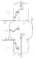
- FIGS. 1 and 2show the device during two different process phases, the basic structure of the device will be explained in more detail. Since the basic principle of pretreatment and coating of substrates by means of a plasmatrone is known, only the essential features associated with the invention will be discussed. In the present example, it is also assumed that the substrates to be subjected to a plasma surface treatment consist of metal.
- the devicehas a central treatment chamber 1, in which a plasma spraying device 10 is accommodated.
- the plasma spraying apparatus 10is disposed on a pivotal mechanism 11 movable in three planes.
- an antechamber 2, 3is arranged, which is laterally provided with a liftable lid 4, 5 each. When the cover 4, 5 is lifted off, the respective substrate S1, S2 can be fed to or removed from the prechamber 2, 3.
- Both atria 2, 3are each provided with a plasmatron 20, 30. Each plasmatron 20, 30 is attached to a pivoting mechanism 21, 31. Each prechamber 2, 3 is associated with a holding device 23, 33, which is designed to receive a substrate S1, S2. At the end of the respective holding device 23, 33, a clamping device 24, 34 is arranged, by means of which the substrate S1, S2 can be tightened. Each lid 4, 5 is provided with an opening 6, 7 for performing the holding device 23, 33.
- the holding devices 23, 33are movable in the longitudinal direction so far that the respective substrate S1, S2 outside the antechamber 2, 3 in the holding device 23, 33 or the clamping device 24, 34 clamped and can be transferred from the holding device 23, 33 in the treatment chamber 1.
- the holding devices 23, 33are also rotatable about their longitudinal axis, so that for the purpose of a uniform pretreatment or coating, the substrate S1, S2 can be rotated both during the pretreatment as well as during coating in the respectively optimal position.
- a slider 27, 37is provided, by means of which the treatment chamber 1 against the respective prechamber 2, 3 is tightly lockable.
- the essentially round shaped slide 27, 37are each guided in a receptacle 28, 38.
- the slide receivers 28, 38are provided with seals 29, 39. It is understood that in the area of the two covers 4, 5 seals are provided, which, however, are not shown in favor of a clear representation.
- Fig. 1shown first phase, the slide 37 is opened between the right antechamber 3 and the treatment chamber 1, while the slide 27 between the left pre-chamber 2 and the treatment chamber 1 is closed.
- an atmosphere adapted to the respective processcan be created in the left prechamber 2 and in the treatment chamber 1 together with the right prechamber 3, and a mutual influence on the respective process can be avoided.
- a negative pressure of the order of magnitude of approximately 10 to 50 mbarprevails both in the left prechamber 2 and in the treatment chamber 1.
- the first substrate S1 clamped in the holding device 33is coated in the treatment chamber 1 by means of the plasma spraying device 10.
- the coating jet emerging from the coating apparatus 10bears the reference numeral 12.
- a second substrate S2is pretreated by means of the plasmatron 20 in the left prechamber 2.
- a cleaning and heatingwherein in Fig. 1 the heating of the substrate S2 by means of a plasma flame 25 and in Fig. 2 the cleaning by a plasma 25A transferred from the plasmatron to the substrate is shown schematically.
- the substrate S2By switching the substrate S2 as a cathode and generating an arc 25A transmitted between the plasmatron 20 and the substrate S2, an electron flow from the second substrate S2 to the plasmatron 20 is effected, so that the surface of the substrate S2 is freed of impurities and oxides.
- This processis known to the skilled person by the term "sputtering".
- the substrate S2is alternately subjected to a cleaning and a heating process. It is understood that the first substrate S1 located in the processing chamber 1 was also cleaned and heated in the aforementioned manner prior to the plasma coating.
- the holding device 33is shifted to the right. As soon as the substrate S1 is in the right pre-chamber, the slider 37 is closed ( Fig. 3 ) and then the slider 27 is opened. In order to lift the cover 5 of the right antechamber 3 and remove the finished coated substrate S1, the pressure in the right antechamber 3 is increased to the atmospheric pressure. After lifting off the cover 5, the holding device 33 is displaced to the right to the extent that the finished coated substrate S1 can be stretched out of the clamping device 34 and replaced by a new one ( Fig. 4 ). At the same time, the second substrate S2 can now be transferred from the left prechamber 2 into the treatment chamber 1. After the holding device 33, together with a new substrate, has been moved back into the right prechamber 3, the lid 5 can be closed and the right prechamber 3 again evacuated.
- the substrate S2 accommodated in the treatment chamber 1can in turn be coated by means of the plasma spraying device 10, while in the right antechamber 2 the further substrate S3 is simultaneously pretreated by means of the plasmatron 30 in the aforementioned manner ( Fig. 5 ).
- the substratecan be transferred after pretreatment of the antechamber in the treatment chamber, without the risk of oxidation of the cleaned substrate surface.
Landscapes
- Chemical & Material Sciences (AREA)
- Engineering & Computer Science (AREA)
- Chemical Kinetics & Catalysis (AREA)
- Materials Engineering (AREA)
- Mechanical Engineering (AREA)
- Metallurgy (AREA)
- Organic Chemistry (AREA)
- Physics & Mathematics (AREA)
- Plasma & Fusion (AREA)
- Physical Vapour Deposition (AREA)
- Chemical Vapour Deposition (AREA)
- Coating By Spraying Or Casting (AREA)
Description
Translated fromGermanUm eine möglichst gute Qualität der mittels einer Plasmaspritzvorrichtung auf ein Substrat aufgetragenen Schicht zu erhalten, muss einerseits die Oberfläche des Substrats sauber sein und zum anderen muss das Substrat auf eine bestimmte Temperatur erhitzt werden. Beide Faktoren tragen dazu bei, eine gute Bindung zwischen dem Substrat und der aufgetragenen Schicht zu gewährleisten.In order to obtain the best possible quality of the applied by means of a plasma spraying device to a substrate layer, on the one hand the surface of the substrate must be clean and on the other hand, the substrate must be heated to a certain temperature. Both factors help to ensure a good bond between the substrate and the applied layer.
Das Plasma-Beschichten von Substraten findet im Normalfall in einer Behandlungskammer statt, in welcher zumeist ein Unterdruck erzeugt wird, damit die Oxidationsgefahr weitgehend gebannt ist. Bei bekannten Verfahren wird das zu beschichtende Substrat in die eigentliche Behandlungskammer eingeführt, in der es zuerst gereinigt, dann erhitzt und anschliessend beschichtet wird. Somit hängt die Behandlungszeit des Substrats nicht allein von der für den eigentlichen Beschichtungsvorgang benötigten Zeit ab, sondern sie wird durch das Reinigen und Erhitzen des Substrats massgeblich verlängert. Vorrichtungen zum Aufbringen von Schichten sind beispielsweise in der
Es ist daher die Aufgabe der Erfindung ein Verfahren sowie eine Einrichtung zur Plasma-Oberflächenbehandlung von Substraten vorzuschlagen, mittels welchem bzw. welcher der Durchsatz massgeblich gesteigert werden kann, wobei die Qualität der aufgetragenen Schicht qualitativ hohen Anforderungen genügen soll.It is therefore an object of the invention to propose a method and a device for plasma surface treatment of substrates, by means of which or which of the throughput can be significantly increased, the quality of the applied layer should meet high quality requirements.
Diese Aufgabe wird durch die im Kennzeichen des Anspruchs 1 angeführten Verfahrensschritte bzw. die im Kennzeichen des Anspruchs 9 aufgeführten Merkmale gelöst.This object is achieved by the method steps mentioned in the characterizing part of
Indem das zeitintensive, dem eigentlichen Beschichtungsvorgang vorangehende Vorbehandeln des Substrats ausserhalb der Behandlungskammer durchgeführt wird, kann in der Behandlungskammer ein Substrat plasmabeschichtet werden, währenddem zeitgleich ein nachfolgend zu beschichtendes Substrat ausserhalb der Behandlungskammer vorbehandelt werden kann. Dadurch kann die Verweilzeit des Substrats in der Behandlungskammer verkürzt und der Durchsatz erhöht werden. Unter zeitgleich ist zu verstehen, dass sich der Beschichtungsvorgang und das Vorbehandeln zeitlich zumindest teilweise überlappen. Zeitgleich ist jedoch keinesfalls so zu interpretieren, dass beide Vorgänge gleich lange dauern müssen oder dass die beiden Vorgänge zum gleichen Zeitpunkt gestartet oder beendet werden müssen.By carrying out the time-consuming pretreatment of the substrate preceding the actual coating process outside the treatment chamber, a substrate can be plasma-coated in the treatment chamber, while at the same time a substrate to be subsequently coated can be pretreated outside the treatment chamber. As a result, the residence time of the substrate in the treatment chamber can be shortened and the throughput can be increased. At the same time, it is to be understood that the coating process and the pretreatment at least partially overlap in time. At the same time, however, it is by no means to be interpreted that both processes must take the same amount of time or that the two processes have to be started or ended at the same time.
Erfahrungswerte zeigen, dass die zum Vorbehandeln (Reinigen und Erhitzen) des Substrats benötigte Zeit ca. dem 0.5 bis 2-fachen der eigentlichen Beschichtungszeit entspricht. Das heisst mit anderen Worten, dass durch ein ausserhalb der Behandlungskammer durchgeführtes Vorbehandeln des Substrats der Durchsatz um ca. 50 bis 100% erhöht werden kann.Experience has shown that the time required for pretreatment (cleaning and heating) of the substrate is approximately 0.5 to 2 times the actual coating time. In other words, by pretreating the substrate outside the treatment chamber, the throughput can be increased by about 50 to 100%.
Bevorzugte Verfahrensschritte sind in den abhängigen Ansprüchen 2 bis 11 umschrieben, währenddem bevorzugte Weiterbildungen der Einrichtung in den abhängigen Ansprüchen 13 bis 21 definiert sind.Preferred method steps are described in the
Anhand von Zeichnungen wird nachfolgend eine bevorzugte Variante des erfindungsgemässen Verfahrens sowie eine bevorzugte Ausführungsform der erfindungsgemässen Einrichtung näher erläutert. In diesen Zeichnungen zeigt:
Fig. 1 die Einrichtung während einer ersten Prozess-Phase;Fig. 2 die Einrichtung während einer zweiten Prozess-Phase;Fig. 3 die Einrichtung während einer dritten Prozess-Phase;Fig. 4 die Einrichtung während einer vierten Prozess-Phase, undFig. 5 die Einrichtung während einer fünften Prozess-Phase.
Fig. 1 the establishment during a first process phase;Fig. 2 the device during a second process phase;Fig. 3 the establishment during a third process phase;Fig. 4 the establishment during a fourth process phase, andFig. 5 the establishment during a fifth process phase.
Anhand der
Die Einrichtung weist eine zentrale Behandlungskammer 1 auf, in der eine Plasmaspritzvorrichtung 10 aufgenommen ist. Die Plasmaspritzvorrichtung 10 ist an einem in drei Ebenen beweglichen Schwenkmechanismus 11 angeordnet. Auf beiden Seiten der Behandlungskammer 1 ist je eine Vorkammer 2, 3 angeordnet, welche seitlich mit je einem abhebbaren Deckel 4, 5 versehen ist. Bei abgehobenem Deckel 4, 5 kann das jeweilige Substrat S1, S2 der Vorkammer 2, 3 zugeführt bzw. aus dieser entnommen werden.The device has a
Beide Vorkammern 2, 3 sind mit je einem Plasmatron 20, 30 versehen. Jedes Plasmatron 20, 30 ist an einem Schwenkmechanismus 21, 31 befestigt. Jeder Vorkammer 2, 3 ist eine Haltevorrichtung 23, 33 zugeordnet, welche zur Aufnahme eines Substrats S1, S2 ausgebildet ist. Am Ende der jeweiligen Haltevorrichtung 23, 33 ist eine Spannvorrichtung 24, 34 angeordnet, mittels welcher das Substrat S1, S2 festgespannt werden kann. Jeder Deckel 4, 5 ist mit einer Öffnung 6, 7 zum Durchführen der Haltevorrichtung 23, 33 versehen. Die Haltevorrichtungen 23, 33 sind in Längsrichtung soweit bewegbar, dass das jeweilige Substrat S1, S2 ausserhalb der Vorkammer 2, 3 in die Haltevorrichtung 23, 33 bzw. die Spannvorrichtung 24, 34 eingespannt und von der Haltevorrichtung 23, 33 in die Behandlungskammer 1 überführt werden kann. Die Haltevorrichtungen 23, 33 sind zudem um ihre Längsachse drehbar, so dass zum Zwecke einer gleichmässigen Vorbehandlung bzw. Beschichtung das Substrat S1, S2 sowohl während des Vorbehandelns wie auch während des Beschichtens in die jeweils optimale Position gedreht werden kann.Both
Zwischen der Behandlungskammer 1 und den beiden Vorkammern 2, 3 ist je ein Schieber 27, 37 vorgesehen, mittels welchem die Behandlungskammer 1 gegenüber der jeweiligen Vorkammer 2, 3 dicht abschliessbar ist. Die im wesentlichen rund ausgebildeten Schieber 27, 37 sind in je einer Aufnahme 28, 38 geführt. In den
Zum Evakuieren der Behandlungskammer 1 sowie der beiden Vorkammern 2, 3 ist eine Vakuumanlage vorgesehen, welche zugunsten einer übersichtlichen Darstellung jedoch ebenfalls nicht eingezeichnet ist. Da derartige Vakuumanlagen zudem bekannt sind, erübrigt es sich, an dieser Stelle näher darauf einzugehen.For evacuating the
Die Funktionsweise der Einrichtung wird nachfolgend anhand der
Das in der Haltevorrichtung 33 eingespannte erste Substrat S1 wird in der Behandlungskammer 1 mittels der Plasmaspritzvorrichtung 10 beschichtet. Der aus der Beschichtungsvorrichtung 10 austretende Beschichtungsstrahl trägt das Bezugszeichen 12. Gleichzeitig mit dem Beschichten des ersten Substrats S1 wird in der linken Vorkammer 2 ein zweites Substrat S2 mittels des Plasmatrons 20 vorbehandelt. Unter Vorbehandeln wird im vorliegenden Fall ein Reinigen und Erhitzen verstanden, wobei in
Nachdem das erste Substrat S1 beschichtet und das zweite Substrat S2 gereinigt und erhitzt wurde, wird die Haltevorrichtung 33 nach rechts verschoben. Sobald sich das Substrat S1 in der rechten Vorkammer befindet, wird der Schieber 37 geschlossen (
Danach kann das in der Behandlungskammer 1 aufgenommene Substrat S2 wiederum mittels der Plasmaspritzvorrichtung 10 beschichtet werden, währenddem in der rechten Vorkammer 2 gleichzeitig das weitere Substrat S3 mittels des Plasmatrons 30 in der vorerwähnten Art vorbehandelt wird (
Indem sowohl die Vorkammern 2, 3 wie auch die Behandlungskammer 1 evakuierbar sind, kann das Substrat nach dem Vorbehandeln von der Vorkammer in die Behandlungskammer überführt werden, ohne dass die Gefahr eines Oxydierens der gereinigten Substratoberfläche besteht.By both the
Es versteht sich, dass das vorgängige Beispiel lediglich eine mögliche Variante des erfindungsgemässen Verfahrens zusammen mit einer bevorzugte Ausführungsform der erfindungsgemässen Einrichtung umschreibt, und dass im Rahmen des in den Patentansprüchen definierten Schutzumfangs durchaus von vorgängigem Beispiel abweichende Ausführungsformen des Verfahrens sowie der Einrichtung möglich sind. Beispielsweise wäre es denkbar, anstelle von zwei Vorkammern mem auch deren drei vorzusehen. Auch die Art und Anordnung der Haltevorrichtungen kann durchaus anders gewählt werden.It is understood that the preceding example describes only one possible variant of the method according to the invention together with a preferred embodiment of the device according to the invention, and that within the scope of the scope defined in the patent claims different embodiments of the method and the device are entirely possible. For example, it would be conceivable instead of two prechambers mem also provide their three. The type and arrangement of the holding devices can also be chosen differently.
Claims (16)
- Method for the plasma surface treatment of substrates,characterised by the following method sequence:- a first substrate (S1) is plasma-coated in a treatment chamber (1) while at the same time a second substrate (S2) to be subsequently coated is heated and cleaned in a first pre-chamber (2) by means of a first plasmatron (20), wherein the plasmatron is moved during heating and cleaning;- the first substrate (S1) is thereafter removed from the treatment chamber (1) and the second substrate (S2) is transferred into the treatment chamber (1) and plasma-coated therein by means of a plasma-spraying device (10);- during the coating of the second substrate (S2) in the treatment chamber (1) a third substrate (S3) is simultaneously heated and cleaned in a second pre-chamber (3) by means of a further plasmatron (30), wherein the plasmatron is moved during heating and cleaning.
- Method in accordance with claim 1,
characterised in that
the second substrate (S2) is switched as a cathode for the cleaning and an arc (25A) is produced which is transferred from the plasmatron (20) onto the substrate (S2). - Method in accordance with any one of the preceding claims,
characterised in that
an underpressure is produced in the treatment chamber (1) at least during the plasma-coating of a substrate (S1). - Method in accordance with any one of the preceding claims,
characterised in that
an underpressure is produced in the pre-chamber (2) at least during the pre-treatment of a substrate (S2). - Method in accordance with any one of the preceding claims,
characterised in that
substrates (S2, S3) which are to be treated one after the other are alternately pre-treated in a first pre-treatment chamber (2) and a second pre-treatment chamber (3) respectively. - Method in accordance with any one of the preceding claims,
characterised in that
the respective pre-chamber (2, 3) is closed off during the pre-treatment of a substrate (2, 3) both with respect to the environmental atmosphere and also with respect to the treatment chamber (1). - Method in accordance with any one of the preceding claims,
characterised in that
the substrate (S2, S3) is moved during the pre-treatment. - Method in accordance with any one of the preceding claims,
characterised in that
the substrate (S1) and/or the plasmatron (10) is moved or are moved during the plasma-coating. - Apparatus for carrying out the method in accordance with any one of the preceding claims, including a treatment chamber (1) which can be evacuated with a plasma-spraying device (10) arranged therein and also two pre-chambers (2, 3) for the pre-treatment of a substrate (S1, S2) which is to be subsequently transferred to the treatment chamber (1),
characterised in that
two pre-chambers (2, 3) are provided adjoining the treatment chamber (1) which are each connected via a closable opening (26, 36) to the treatment chamber (1) andin that a plasmatron (20, 30) is provided which is moveably arranged for the pre-treatment of the substrate (S1, S2) which is subsequently to be coated in the treatment chamber (1) in each pre-chamber (2, 3) andin that a holding device (23, 33) for the clamping of the substrate (S1, S2) is associated with each pre-chamber (2, 3). - Apparatus in accordance with claim 9,
characterised in that
a slide (27, 37) for the closing off of the opening (26, 36) is associated with each pre-chamber (2, 3). - Apparatus in accordance with any one of the claims 9 and 10,
characterised in that
each pre-chamber (2, 3) is provided with a closable cover (4, 5), with each cover (4, 5) being provided with an opening (6, 7) for the through movement of the holding device (23, 33). - Apparatus in accordance with any one of the claims 9 to 11,
characterised in that
the holding device(s) (23, 33) is/are made movable in the longitudinal direction andin that the respective holding device (23, 33) is movable by at least the length of a pre-chamber (2, 3). - Apparatus in accordance with any one of the claims 9 to 12,
characterised in that
each holding device (23, 33) is provided at an end with a clamping device (24, 34). - Apparatus in accordance with claim 13,
characterised in that
at least the clamping device (24, 34) is rotatably formed. - Apparatus in accordance with any one of the claims 9 to 14,
characterised in that
the pre-chambers (2, 3) lie diametrically opposite to one another. - Apparatus in accordance with any one of the claims 9 to 15,
characterised in that
the holding devices (23, 33) are so displaceably arranged that the substrate (S1, S2) clamped therein can be moved from the pre-chamber (2, 3) via the respective opening (26, 36) into the treatment chamber (1) and back again.
Applications Claiming Priority (2)
| Application Number | Priority Date | Filing Date | Title |
|---|---|---|---|
| CH02395/98ACH697036A5 (en) | 1998-12-02 | 1998-12-02 | A method for plasma surface treatment of substrates, as well as means for performing the method. |
| CH239598 | 1998-12-02 |
Publications (3)
| Publication Number | Publication Date |
|---|---|
| EP1006211A1 EP1006211A1 (en) | 2000-06-07 |
| EP1006211B1 EP1006211B1 (en) | 2004-12-08 |
| EP1006211B2true EP1006211B2 (en) | 2011-03-16 |
Family
ID=4232779
Family Applications (1)
| Application Number | Title | Priority Date | Filing Date |
|---|---|---|---|
| EP99810972AExpired - LifetimeEP1006211B2 (en) | 1998-12-02 | 1999-10-27 | Method and apparatus for plasma treatment of substrates |
Country Status (6)
| Country | Link |
|---|---|
| EP (1) | EP1006211B2 (en) |
| JP (1) | JP4636641B2 (en) |
| CA (1) | CA2289873C (en) |
| CH (1) | CH697036A5 (en) |
| DE (1) | DE59911235D1 (en) |
| SG (1) | SG79289A1 (en) |
Families Citing this family (7)
| Publication number | Priority date | Publication date | Assignee | Title |
|---|---|---|---|---|
| RU2402628C1 (en)* | 2009-03-23 | 2010-10-27 | Государственное образовательное учреждение высшего профессионального образования "Кубанский государственный технологический университет" (ГОУВПО "КубГТУ") | Device for production of nano-structured coating of parts with cylinder surface and shape memory effect |
| EP2439305A1 (en) | 2010-10-07 | 2012-04-11 | Sulzer Metco AG | Thermal spray process avoiding the blockage of cooling holes in turbine components |
| RU2475567C1 (en)* | 2011-06-17 | 2013-02-20 | Государственное образовательное учреждение высшего профессионального образования "Кубанский государственный технологический университет " (ГОУВПО "КубГТУ") | Plant for obtaining nanostructured coatings from material with shape memory effect on cylindrical surface of parts |
| RU2674532C1 (en)* | 2018-06-15 | 2018-12-11 | Федеральное государственное бюджетное образовательное учреждение высшего образования "Кубанский государственный технологический университет" (ФГБОУ ВО "КубГТУ") | Vacuum unit for nanostructured coating made of material with shape memory effect on part surface |
| RU2762082C1 (en)* | 2020-12-14 | 2021-12-15 | Федеральное государственное казенное военное образовательное учреждение высшего образования "Военный учебно-научный центр Военно-воздушных сил "Военно-воздушная академия имени профессора Н.Е. Жуковского и Ю.А. Гагарина" (г. Воронеж) Министерства обороны Российской Федерации | Unit for applying composite materials on the surface of parts by plasma spraying |
| CN112974071B (en)* | 2021-02-23 | 2022-07-15 | 山东大学 | A coating surface modification device and working method based on thermal spraying process |
| CN115323307A (en)* | 2022-08-15 | 2022-11-11 | 奈文摩尔洛阳科技有限公司 | Nano zirconia thermal barrier coating plasma spraying device |
Citations (14)
| Publication number | Priority date | Publication date | Assignee | Title |
|---|---|---|---|---|
| GB1447754A (en)† | 1972-06-15 | 1976-09-02 | Secr Defence | Apparatus for and process of metal coating |
| US4090941A (en)† | 1977-03-18 | 1978-05-23 | United Technologies Corporation | Cathode sputtering apparatus |
| US4116791A (en)† | 1976-05-19 | 1978-09-26 | Battelle Memorial Institute | Method and apparatus for forming a deposit by means of ion plating using a magnetron cathode target as source of coating material |
| DE2812271A1 (en)† | 1978-03-21 | 1979-10-04 | Leybold Heraeus Gmbh & Co Kg | DEVICE FOR COATING SUBSTRATES IN BATCHS WITH MULTIPLE LOCK CHAMBERS |
| US4500564A (en)† | 1982-02-01 | 1985-02-19 | Agency Of Industrial Science & Technology | Method for surface treatment by ion bombardment |
| JPS6212693A (en)† | 1985-07-05 | 1987-01-21 | Nissin Electric Co Ltd | Epitaxial growth apparatus |
| GB2178227A (en)† | 1985-06-17 | 1987-02-04 | Honda Motor Co Ltd | Vacuum treating method and apparatus |
| EP0248117A2 (en)† | 1986-06-03 | 1987-12-09 | Aesculap Ag | Method of applying an abradable coating to endoarticulated prostheses |
| DD291783A5 (en)† | 1990-02-05 | 1991-07-11 | Fi "Manfred Von Ardenne",De | Zersteubungseinrichtung with rotating substrate carrier |
| EP0477990A2 (en)† | 1990-09-28 | 1992-04-01 | Applied Materials, Inc. | A method of enhancing the properties of a thin film on a substrate |
| DE4135326C1 (en)† | 1991-10-25 | 1993-06-09 | Siemens Ag, 8000 Muenchen, De | Coating components by thermal spraying - using preheating kiln to heat workpiece before plasma spraying in vacuum chamber |
| DE4228499C1 (en)† | 1992-09-01 | 1993-10-07 | Dresden Vakuumtech Gmbh | Plasma-aided coating of substrates - with a low-voltage arc discharge between a cathode and an anodic electrode |
| JPH07305158A (en)† | 1994-05-06 | 1995-11-21 | Nippon Steel Corp | Thermal spray pretreatment method |
| DE4427259A1 (en)† | 1994-07-30 | 1996-02-01 | Mtu Muenchen Gmbh | Method and apparatus for cleaning or preheating the surface of workpieces |
Family Cites Families (2)
| Publication number | Priority date | Publication date | Assignee | Title |
|---|---|---|---|---|
| JPH0586451A (en)* | 1991-09-27 | 1993-04-06 | Nippon Steel Corp | Vacuum plasma thermal spraying method and device therefor |
| US5470661A (en)* | 1993-01-07 | 1995-11-28 | International Business Machines Corporation | Diamond-like carbon films from a hydrocarbon helium plasma |
- 1998
- 1998-12-02CHCH02395/98Apatent/CH697036A5/ennot_activeIP Right Cessation
- 1999
- 1999-10-27DEDE1999511235patent/DE59911235D1/ennot_activeExpired - Lifetime
- 1999-10-27EPEP99810972Apatent/EP1006211B2/ennot_activeExpired - Lifetime
- 1999-11-03SGSG9905452Apatent/SG79289A1/enunknown
- 1999-11-17CACA002289873Apatent/CA2289873C/ennot_activeExpired - Fee Related
- 1999-12-02JPJP34309099Apatent/JP4636641B2/ennot_activeExpired - Fee Related
Patent Citations (14)
| Publication number | Priority date | Publication date | Assignee | Title |
|---|---|---|---|---|
| GB1447754A (en)† | 1972-06-15 | 1976-09-02 | Secr Defence | Apparatus for and process of metal coating |
| US4116791A (en)† | 1976-05-19 | 1978-09-26 | Battelle Memorial Institute | Method and apparatus for forming a deposit by means of ion plating using a magnetron cathode target as source of coating material |
| US4090941A (en)† | 1977-03-18 | 1978-05-23 | United Technologies Corporation | Cathode sputtering apparatus |
| DE2812271A1 (en)† | 1978-03-21 | 1979-10-04 | Leybold Heraeus Gmbh & Co Kg | DEVICE FOR COATING SUBSTRATES IN BATCHS WITH MULTIPLE LOCK CHAMBERS |
| US4500564A (en)† | 1982-02-01 | 1985-02-19 | Agency Of Industrial Science & Technology | Method for surface treatment by ion bombardment |
| GB2178227A (en)† | 1985-06-17 | 1987-02-04 | Honda Motor Co Ltd | Vacuum treating method and apparatus |
| JPS6212693A (en)† | 1985-07-05 | 1987-01-21 | Nissin Electric Co Ltd | Epitaxial growth apparatus |
| EP0248117A2 (en)† | 1986-06-03 | 1987-12-09 | Aesculap Ag | Method of applying an abradable coating to endoarticulated prostheses |
| DD291783A5 (en)† | 1990-02-05 | 1991-07-11 | Fi "Manfred Von Ardenne",De | Zersteubungseinrichtung with rotating substrate carrier |
| EP0477990A2 (en)† | 1990-09-28 | 1992-04-01 | Applied Materials, Inc. | A method of enhancing the properties of a thin film on a substrate |
| DE4135326C1 (en)† | 1991-10-25 | 1993-06-09 | Siemens Ag, 8000 Muenchen, De | Coating components by thermal spraying - using preheating kiln to heat workpiece before plasma spraying in vacuum chamber |
| DE4228499C1 (en)† | 1992-09-01 | 1993-10-07 | Dresden Vakuumtech Gmbh | Plasma-aided coating of substrates - with a low-voltage arc discharge between a cathode and an anodic electrode |
| JPH07305158A (en)† | 1994-05-06 | 1995-11-21 | Nippon Steel Corp | Thermal spray pretreatment method |
| DE4427259A1 (en)† | 1994-07-30 | 1996-02-01 | Mtu Muenchen Gmbh | Method and apparatus for cleaning or preheating the surface of workpieces |
Non-Patent Citations (3)
| Title |
|---|
| Auszug aus "Wikipedia" http://de.wikipedia.org/wiki/Lichtbogen vom 12.10.2007† |
| Auszug aus "Wikipedia" http://de.wikipedia.org/wiki/Tron vom 15.05.2006† |
| Technische Spezifikation "Elektronenstrahl-Springstrahlanlage, Typ ESPRI 150", von Ardenne Anlagentechnik GmbH, 12.11.1993, Dresden† |
Also Published As
| Publication number | Publication date |
|---|---|
| DE59911235D1 (en) | 2005-01-13 |
| JP4636641B2 (en) | 2011-02-23 |
| EP1006211A1 (en) | 2000-06-07 |
| JP2000169950A (en) | 2000-06-20 |
| CA2289873A1 (en) | 2000-06-02 |
| EP1006211B1 (en) | 2004-12-08 |
| CH697036A5 (en) | 2008-03-31 |
| SG79289A1 (en) | 2001-03-20 |
| CA2289873C (en) | 2006-02-28 |
Similar Documents
| Publication | Publication Date | Title |
|---|---|---|
| DE4126236C2 (en) | Rotating magnetron cathode and use of a rotating magnetron cathode | |
| DE3872859T2 (en) | METHOD FOR METALLIZING A SILICATE, QUARTZ, GLASS OR SAPPHIRE SUBSTRATE AND SUBSTRATE OBTAINED THEREFORE. | |
| DE4123959C1 (en) | ||
| DE3507337A1 (en) | DEVICE FOR CARRYING OUT VACUUM PROCESSES | |
| DE2241634B2 (en) | Process for the continuous application of metallic coatings on flat workpieces by means of cathode sputtering | |
| DE2812271A1 (en) | DEVICE FOR COATING SUBSTRATES IN BATCHS WITH MULTIPLE LOCK CHAMBERS | |
| EP1036212B1 (en) | Device for vacuum coating slide bearings | |
| DD207927A5 (en) | plasma etching | |
| EP1006211B2 (en) | Method and apparatus for plasma treatment of substrates | |
| DE102006057386A1 (en) | Method for coating a substrate with a catalytically active material comprises charging a vacuum chamber with a substrate, closing and evacuating the chamber, cleaning the substrate and further processing | |
| DE19606463C2 (en) | Multi-chamber sputtering device | |
| EP0888463A1 (en) | Means for vacuum coating of bulk material | |
| DE19626861B4 (en) | Vacuum treatment system for applying thin layers to substrates, for example to headlight reflectors | |
| CH688043A5 (en) | Vakuumbehandlungsanlage and Ventilanordnung. | |
| DE4040856A1 (en) | SPRAYING SYSTEM | |
| EP0874921B1 (en) | Process and system for electrochemical treatment of long stretched-out items | |
| EP0142083A2 (en) | Method and apparatus for the production of metallic coatings | |
| EP1715078A1 (en) | Continuous OLED coating apparatus | |
| DE2134377C3 (en) | Process for the deposition of thin layers on metallic workpieces by means of cathode sputtering | |
| EP0627496A2 (en) | Method and device for coating metal substrates, especially steel- and aluminium-sheets in shape of tapes | |
| CH663220A5 (en) | METHOD FOR PRODUCING LAYERING MATERIAL OR LAYERING PIECES. | |
| DE4307740C2 (en) | Method for producing housings with at least one metallic shielding layer | |
| DE3413142C1 (en) | Method for manufacturing a superconducting cavity resonator | |
| DE3806174A1 (en) | METHOD AND DEVICE FOR APPLYING LAYERS OF HIGH-TEMPERATURE-SUPRAL-CONDUCTING MATERIAL TO SUBSTRATES | |
| WO1989008332A1 (en) | Process and device for depositing layers of a high-temperature superconducting material on substrates |
Legal Events
| Date | Code | Title | Description |
|---|---|---|---|
| PUAI | Public reference made under article 153(3) epc to a published international application that has entered the european phase | Free format text:ORIGINAL CODE: 0009012 | |
| AK | Designated contracting states | Kind code of ref document:A1 Designated state(s):DE FR GB IT NL | |
| AX | Request for extension of the european patent | Free format text:AL;LT;LV;MK;RO;SI | |
| 17P | Request for examination filed | Effective date:20000706 | |
| AKX | Designation fees paid | Free format text:DE FR GB IT NL | |
| 17Q | First examination report despatched | Effective date:20020508 | |
| GRAP | Despatch of communication of intention to grant a patent | Free format text:ORIGINAL CODE: EPIDOSNIGR1 | |
| GRAS | Grant fee paid | Free format text:ORIGINAL CODE: EPIDOSNIGR3 | |
| GRAA | (expected) grant | Free format text:ORIGINAL CODE: 0009210 | |
| AK | Designated contracting states | Kind code of ref document:B1 Designated state(s):DE FR GB IT NL | |
| REG | Reference to a national code | Ref country code:GB Ref legal event code:FG4D Free format text:NOT ENGLISH | |
| GBT | Gb: translation of ep patent filed (gb section 77(6)(a)/1977) | Effective date:20041208 | |
| REF | Corresponds to: | Ref document number:59911235 Country of ref document:DE Date of ref document:20050113 Kind code of ref document:P | |
| PLAQ | Examination of admissibility of opposition: information related to despatch of communication + time limit deleted | Free format text:ORIGINAL CODE: EPIDOSDOPE2 | |
| PLBQ | Unpublished change to opponent data | Free format text:ORIGINAL CODE: EPIDOS OPPO | |
| PLAQ | Examination of admissibility of opposition: information related to despatch of communication + time limit deleted | Free format text:ORIGINAL CODE: EPIDOSDOPE2 | |
| PLAR | Examination of admissibility of opposition: information related to receipt of reply deleted | Free format text:ORIGINAL CODE: EPIDOSDOPE4 | |
| PLBI | Opposition filed | Free format text:ORIGINAL CODE: 0009260 | |
| PLBQ | Unpublished change to opponent data | Free format text:ORIGINAL CODE: EPIDOS OPPO | |
| 26 | Opposition filed | Opponent name:SIEMENSABTEILUNG: CT IP TS Effective date:20050524 | |
| NLR1 | Nl: opposition has been filed with the epo | Opponent name:SIEMENS ABTEILUNG: CT IP TS | |
| PLAX | Notice of opposition and request to file observation + time limit sent | Free format text:ORIGINAL CODE: EPIDOSNOBS2 | |
| ET | Fr: translation filed | ||
| PLAF | Information modified related to communication of a notice of opposition and request to file observations + time limit | Free format text:ORIGINAL CODE: EPIDOSCOBS2 | |
| PLBB | Reply of patent proprietor to notice(s) of opposition received | Free format text:ORIGINAL CODE: EPIDOSNOBS3 | |
| PLAO | Information deleted related to despatch of communication that opposition is rejected | Free format text:ORIGINAL CODE: EPIDOSDREJ1 | |
| PLCK | Communication despatched that opposition was rejected | Free format text:ORIGINAL CODE: EPIDOSNREJ1 | |
| APAH | Appeal reference modified | Free format text:ORIGINAL CODE: EPIDOSCREFNO | |
| APBP | Date of receipt of notice of appeal recorded | Free format text:ORIGINAL CODE: EPIDOSNNOA2O | |
| APBQ | Date of receipt of statement of grounds of appeal recorded | Free format text:ORIGINAL CODE: EPIDOSNNOA3O | |
| APBU | Appeal procedure closed | Free format text:ORIGINAL CODE: EPIDOSNNOA9O | |
| PUAH | Patent maintained in amended form | Free format text:ORIGINAL CODE: 0009272 | |
| STAA | Information on the status of an ep patent application or granted ep patent | Free format text:STATUS: PATENT MAINTAINED AS AMENDED | |
| 27A | Patent maintained in amended form | Effective date:20110316 | |
| AK | Designated contracting states | Kind code of ref document:B2 Designated state(s):DE FR GB IT NL | |
| REG | Reference to a national code | Ref country code:DE Ref legal event code:R102 Ref document number:59911235 Country of ref document:DE Effective date:20110316 | |
| REG | Reference to a national code | Ref country code:NL Ref legal event code:T3 | |
| REG | Reference to a national code | Ref country code:FR Ref legal event code:PLFP Year of fee payment:18 | |
| PGFP | Annual fee paid to national office [announced via postgrant information from national office to epo] | Ref country code:FR Payment date:20160919 Year of fee payment:18 | |
| PGFP | Annual fee paid to national office [announced via postgrant information from national office to epo] | Ref country code:GB Payment date:20161026 Year of fee payment:18 Ref country code:NL Payment date:20161010 Year of fee payment:18 | |
| REG | Reference to a national code | Ref country code:NL Ref legal event code:MM Effective date:20171101 | |
| GBPC | Gb: european patent ceased through non-payment of renewal fee | Effective date:20171027 | |
| REG | Reference to a national code | Ref country code:FR Ref legal event code:ST Effective date:20180629 | |
| PG25 | Lapsed in a contracting state [announced via postgrant information from national office to epo] | Ref country code:GB Free format text:LAPSE BECAUSE OF NON-PAYMENT OF DUE FEES Effective date:20171027 Ref country code:NL Free format text:LAPSE BECAUSE OF NON-PAYMENT OF DUE FEES Effective date:20171101 | |
| PG25 | Lapsed in a contracting state [announced via postgrant information from national office to epo] | Ref country code:FR Free format text:LAPSE BECAUSE OF NON-PAYMENT OF DUE FEES Effective date:20171031 | |
| PGFP | Annual fee paid to national office [announced via postgrant information from national office to epo] | Ref country code:DE Payment date:20181031 Year of fee payment:20 | |
| PGFP | Annual fee paid to national office [announced via postgrant information from national office to epo] | Ref country code:IT Payment date:20181108 Year of fee payment:20 | |
| REG | Reference to a national code | Ref country code:DE Ref legal event code:R071 Ref document number:59911235 Country of ref document:DE |