EP1005910A2 - Centrifuge tube with cylindrically symmetric separation element, liner and cap - Google Patents
Centrifuge tube with cylindrically symmetric separation element, liner and capDownload PDFInfo
- Publication number
- EP1005910A2 EP1005910A2EP99124315AEP99124315AEP1005910A2EP 1005910 A2EP1005910 A2EP 1005910A2EP 99124315 AEP99124315 AEP 99124315AEP 99124315 AEP99124315 AEP 99124315AEP 1005910 A2EP1005910 A2EP 1005910A2
- Authority
- EP
- European Patent Office
- Prior art keywords
- liner
- tube
- seal plug
- closure
- septum
- Prior art date
- Legal status (The legal status is an assumption and is not a legal conclusion. Google has not performed a legal analysis and makes no representation as to the accuracy of the status listed.)
- Withdrawn
Links
Images


Classifications
- G—PHYSICS
- G01—MEASURING; TESTING
- G01N—INVESTIGATING OR ANALYSING MATERIALS BY DETERMINING THEIR CHEMICAL OR PHYSICAL PROPERTIES
- G01N33/00—Investigating or analysing materials by specific methods not covered by groups G01N1/00 - G01N31/00
- G01N33/48—Biological material, e.g. blood, urine; Haemocytometers
- G01N33/483—Physical analysis of biological material
- G01N33/487—Physical analysis of biological material of liquid biological material
- G01N33/49—Blood
- G01N33/491—Blood by separating the blood components
- A—HUMAN NECESSITIES
- A61—MEDICAL OR VETERINARY SCIENCE; HYGIENE
- A61B—DIAGNOSIS; SURGERY; IDENTIFICATION
- A61B5/00—Measuring for diagnostic purposes; Identification of persons
- A61B5/15—Devices for taking samples of blood
- A61B5/150007—Details
- A61B5/150015—Source of blood
- A61B5/15003—Source of blood for venous or arterial blood
- A—HUMAN NECESSITIES
- A61—MEDICAL OR VETERINARY SCIENCE; HYGIENE
- A61B—DIAGNOSIS; SURGERY; IDENTIFICATION
- A61B5/00—Measuring for diagnostic purposes; Identification of persons
- A61B5/15—Devices for taking samples of blood
- A61B5/150007—Details
- A61B5/150206—Construction or design features not otherwise provided for; manufacturing or production; packages; sterilisation of piercing element, piercing device or sampling device
- A61B5/150221—Valves
- A—HUMAN NECESSITIES
- A61—MEDICAL OR VETERINARY SCIENCE; HYGIENE
- A61B—DIAGNOSIS; SURGERY; IDENTIFICATION
- A61B5/00—Measuring for diagnostic purposes; Identification of persons
- A61B5/15—Devices for taking samples of blood
- A61B5/150007—Details
- A61B5/150206—Construction or design features not otherwise provided for; manufacturing or production; packages; sterilisation of piercing element, piercing device or sampling device
- A61B5/150236—Pistons, i.e. cylindrical bodies that sit inside the syringe barrel, typically with an air tight seal, and slide in the barrel to create a vacuum or to expel blood
- A—HUMAN NECESSITIES
- A61—MEDICAL OR VETERINARY SCIENCE; HYGIENE
- A61B—DIAGNOSIS; SURGERY; IDENTIFICATION
- A61B5/00—Measuring for diagnostic purposes; Identification of persons
- A61B5/15—Devices for taking samples of blood
- A61B5/150007—Details
- A61B5/150206—Construction or design features not otherwise provided for; manufacturing or production; packages; sterilisation of piercing element, piercing device or sampling device
- A61B5/150251—Collection chamber divided into at least two compartments, e.g. for division of samples
- A—HUMAN NECESSITIES
- A61—MEDICAL OR VETERINARY SCIENCE; HYGIENE
- A61B—DIAGNOSIS; SURGERY; IDENTIFICATION
- A61B5/00—Measuring for diagnostic purposes; Identification of persons
- A61B5/15—Devices for taking samples of blood
- A61B5/150007—Details
- A61B5/150351—Caps, stoppers or lids for sealing or closing a blood collection vessel or container, e.g. a test-tube or syringe barrel
- A—HUMAN NECESSITIES
- A61—MEDICAL OR VETERINARY SCIENCE; HYGIENE
- A61B—DIAGNOSIS; SURGERY; IDENTIFICATION
- A61B5/00—Measuring for diagnostic purposes; Identification of persons
- A61B5/15—Devices for taking samples of blood
- A61B5/150007—Details
- A61B5/150374—Details of piercing elements or protective means for preventing accidental injuries by such piercing elements
- A61B5/150534—Design of protective means for piercing elements for preventing accidental needle sticks, e.g. shields, caps, protectors, axially extensible sleeves, pivotable protective sleeves
- A61B5/150572—Pierceable protectors, e.g. shields, caps, sleeves or films, e.g. for hygienic purposes
- A—HUMAN NECESSITIES
- A61—MEDICAL OR VETERINARY SCIENCE; HYGIENE
- A61B—DIAGNOSIS; SURGERY; IDENTIFICATION
- A61B5/00—Measuring for diagnostic purposes; Identification of persons
- A61B5/15—Devices for taking samples of blood
- A61B5/150007—Details
- A61B5/150755—Blood sample preparation for further analysis, e.g. by separating blood components or by mixing
- A—HUMAN NECESSITIES
- A61—MEDICAL OR VETERINARY SCIENCE; HYGIENE
- A61B—DIAGNOSIS; SURGERY; IDENTIFICATION
- A61B5/00—Measuring for diagnostic purposes; Identification of persons
- A61B5/15—Devices for taking samples of blood
- A61B5/153—Devices specially adapted for taking samples of venous or arterial blood, e.g. with syringes
- A61B5/154—Devices using pre-evacuated means
- B—PERFORMING OPERATIONS; TRANSPORTING
- B01—PHYSICAL OR CHEMICAL PROCESSES OR APPARATUS IN GENERAL
- B01D—SEPARATION
- B01D21/00—Separation of suspended solid particles from liquids by sedimentation
- B01D21/0003—Making of sedimentation devices, structural details thereof, e.g. prefabricated parts
- B—PERFORMING OPERATIONS; TRANSPORTING
- B01—PHYSICAL OR CHEMICAL PROCESSES OR APPARATUS IN GENERAL
- B01D—SEPARATION
- B01D21/00—Separation of suspended solid particles from liquids by sedimentation
- B01D21/26—Separation of sediment aided by centrifugal force or centripetal force
- B—PERFORMING OPERATIONS; TRANSPORTING
- B01—PHYSICAL OR CHEMICAL PROCESSES OR APPARATUS IN GENERAL
- B01D—SEPARATION
- B01D21/00—Separation of suspended solid particles from liquids by sedimentation
- B01D21/26—Separation of sediment aided by centrifugal force or centripetal force
- B01D21/262—Separation of sediment aided by centrifugal force or centripetal force by using a centrifuge
- B—PERFORMING OPERATIONS; TRANSPORTING
- B01—PHYSICAL OR CHEMICAL PROCESSES OR APPARATUS IN GENERAL
- B01L—CHEMICAL OR PHYSICAL LABORATORY APPARATUS FOR GENERAL USE
- B01L3/00—Containers or dishes for laboratory use, e.g. laboratory glassware; Droppers
- B01L3/50—Containers for the purpose of retaining a material to be analysed, e.g. test tubes
- B01L3/502—Containers for the purpose of retaining a material to be analysed, e.g. test tubes with fluid transport, e.g. in multi-compartment structures
- B01L3/5021—Test tubes specially adapted for centrifugation purposes
- B01L3/50215—Test tubes specially adapted for centrifugation purposes using a float to separate phases
- B—PERFORMING OPERATIONS; TRANSPORTING
- B01—PHYSICAL OR CHEMICAL PROCESSES OR APPARATUS IN GENERAL
- B01D—SEPARATION
- B01D2221/00—Applications of separation devices
- B01D2221/10—Separation devices for use in medical, pharmaceutical or laboratory applications, e.g. separating amalgam from dental treatment residues
- B—PERFORMING OPERATIONS; TRANSPORTING
- B01—PHYSICAL OR CHEMICAL PROCESSES OR APPARATUS IN GENERAL
- B01L—CHEMICAL OR PHYSICAL LABORATORY APPARATUS FOR GENERAL USE
- B01L2300/00—Additional constructional details
- B01L2300/04—Closures and closing means
- B01L2300/041—Connecting closures to device or container
- B01L2300/042—Caps; Plugs
Definitions
- This inventionrelates to a device and method for separating heavier and lighter fractions of a fluid sample. More particularly, this invention relates to a device and method for collecting and transporting fluid samples whereby the device and fluid sample are subjected to centrifugation to cause separation of the heavier fraction from the lighter fraction of the fluid sample.
- Diagnostic testsmay require separation of a patient's whole blood sample into components, such as serum or plasma, the lighter phase component, and red blood cells, the heavier phase component.
- Samples of whole bloodare typically collected by venipuncture through a cannula or needle attached to a syringe or an evacuated collection tube. Separation of the blood into serum or plasma and red blood cells is then accomplished by rotation of the syringe or tube in a centrifuge.
- Such arrangementsuse a barrier for moving into an area adjacent the two phases of the sample being separated to maintain the components separated for subsequent examination of the individual components.
- a variety of deviceshave been used in collection devices to divide the area between the heavier and lighter phases of a fluid sample.
- the most widely used deviceincludes thixotropic gel materials such as polyester gels in a tube.
- the present polyester gel serum separation tubesrequire special manufacturing equipment to prepare the gel and to fill the tubes.
- the shelf-life of the productis limited in that overtime globules may be released from the gel mass.
- These globuleshave a specific gravity that is less than the separated serum and may float in the serum and may clog the measuring instruments, such as the instrument probes used during clinical examination of the sample collected in the tube. Such clogging can lead to considerable downtime for the instrument to remove the clog.
- a separator devicethat (i) is easily used to separate a blood sample; (ii) is independent of temperature during storage and shipping; (iii) is stable to radiation sterilization; (iv) employs the benefits of a thixotropic gel barrier yet avoids the many disadvantages of placing a gel in contact with the separated blood components; (v) minimizes cross contamination of the heavier and lighter phases of the sample during centrifugation; (vi) minimizes adhesion of the lower and higher density materials against the separator device; (vii) can be used with standard sampling equipment; (viii) is able to move into position to form a barrier in less time than conventional methods and devices; and (ix) is able to provide a clearer specimen with less cell contamination than conventional methods and devices.
- the present inventionis a method and assembly for separating a fluid sample into a higher specific gravity phase and a lower specific gravity phase.
- the assembly of the present inventioncomprises a plurality of constituents.
- the assemblycomprises a container, a liner and a composite element.
- the containermay be a conventional tube having a closed bottom, an opened top and a rigid cylindrical wall extending therebetween.
- the tubemay include an inwardly directed rim near the open top.
- the assemblyfurther comprises a liner having a closed bottom, an open top and a tubular side wall.
- the lineris positioned in the tube such that the closed bottom of the liner is near the closed bottom of the tube.
- the linerin an unbiased condition, is cross-sectionally dimensioned along most of its length to lie in spaced relationship to the tube.
- the linermay include an outwardly directed flange substantially adjacent the top of the liner. The flange may be dimensioned for engagement against the rim of the tube to position the liner longitudinally within the tube.
- the stiffness coefficientis about .003 to about 190.
- the linerhas a thickness of about 1.0mm to about 2.5mm, a modulus of elasticity of about 13.8 MPa to about 69 MPa.
- the assembly of the present inventionwill function under load created by an applied acceleration of about 300g to about 3000g.
- the linerdeforms due to hydrostatic pressure under applied acceleration and returns to its initial state upon removal of the acceleration, thereby forming a seal by constricting the seal plug which is positioned in a target density region between the higher density portion and the lower density portion of a fluid sample.
- the assemblyfurther includes a tube closure that is sealingly engageable in the open top of the tube.
- the tube closuremay include a tube end seat having an outside diameter at least equal to the outside diameter of the tube for disposition substantially adjacent the open top of the tube.
- the tube closuremay include a tube stopper dimensioned for sealed engagement in portions of the tube between the top of the tube and the top of the liner.
- the tube closuremay further include a liner stopper dimensioned for sealing engagement in the open top of the liner.
- a plug recessextends into the bottom end of the tube closure.
- the entry to the plug recessmay have a plurality of inwardly extending circumferentially spaced flexible walls.
- the composite elementcomprises a seal plug.
- the seal plugmay be a single constituent or a plurality of constituents and comprises a specific density at a target density range as defined by separable fluid components densities.
- the seal plugmay migrate freely when under an applied acceleration to settle at a location in the fluid sample in the target density region and thereby become a barrier at a desired level between the components of the fluid sample after the acceleration is removed.
- the seal plughas an aggregate specific gravity of about 1.028 to about 1.09. Most preferably, the seal plug has an aggregate specific gravity so that it will rest after centrifugal force, between the heavier and lighter phases of a blood sample.
- the seal plugpreferably has an overall density between the densities of two phases of a blood sample.
- the seal plugcomprises a hard plastic shell having opposed first and second ends and an aperture extending between the ends. Outer circumferential portions of the hard plastic shell in proximity to the first end are dimensioned and configured for releasable engagement within the plug recess of the tube closure. Outer circumferential portions of the hard plastic shell in proximity to the second end are dimensioned for sealing engagement by the unbiased tube liner.
- the seal plugfurther includes an elastomeric septum that is securely mounted around the first end of the hard plastic shell to provide a pierceable barrier extending across the central passage through the shell.
- the seal plugcomprises an overall specific gravity at a target specific gravity of ⁇ t.
- the target specific gravityis that required to separate a fluid sample into two phases.
- a fluid sampleenters the assembly by a needle.
- the needlepenetrates the closure and through the elastomeric septum on the seal plug for delivering a fluid sample into the liner.
- the needleis withdrawn from the assembly and the assembly is subjected to centrifugation. Forces exerted by the centrifuge cause the seal plug to separate from the tube closure and cause the liner to expand outwardly against the tube. Centrifugal forces then cause the seal plug to move through the expanded liner and toward the closed bottom of the tube. Sufficient movement will cause the seal plug to contact the fluid. Air trapped in the passage through the hard plastic liner and between the fluid and the elastomeric septum could create a buoyancy that might prevent further sinking of the seal plug into the fluid.
- the trapped airwill be vented through a defect in the septum, such as the defect caused by the needle cannula.
- This venting of airpermits further movement of the seal plug into the fluid.
- the phases of the fluidwill be separating such that the heavier phase component of the fluid will concentrate closer to the closed bottom, and such that the lighter phase component of the fluid will be closer to the open top.
- the seal plugwill move primarily through the lighter phase component and toward the heavier phase component of the fluid.
- the centrifugemay be stopped after the seal plug stabilizes between the separate phases of the fluid.
- the linerUpon termination of the centrifugal load, the liner will resiliently return toward its unexpanded condition and will sealingly engage outer circumferential regions of the seal plug. As a result, the phases of the fluid sample are isolated from one another by the seal plug and may be separated for subsequent analysis.
- the higher specific gravity portion that contains the cellular componentsis between the separator and the bottom of the container after centrifugation.
- the lower specific gravity portion that contains the cell-free serum fraction or plasmais between the top surface of the separator and the top of the container after centrifugation.
- the separatoris able to substantially eliminate the presence of red blood cells in the lower specific gravity portion and the lower specific gravity is substantially free of cellular contamination.
- the assembly of the present inventionis advantageous over existing separation products that use gel.
- the assembly of the present inventionwill not interfere with analytes as compared to gels that may interfere with analytes.
- Another attribute of the present inventionis that the assembly of the present invention will not interfere with therapeutic drug monitoring analytes.
- Another notable advantage of the present inventionis that fluid specimens are not subjected to low density gel residuals that are at times available in products that use gel.
- a further attribute of the present inventionis that there is no interference with instrument probes.
- Another attribute of the present inventionis that samples for blood banking tests are more acceptable than when a gel separator is used.
- Another attribute of the present inventionis that only the substantially cell-free serum fraction of a blood sample is exposed to the top surface of the separator, thus providing practitioners with a clean sample.
- the assembly of the present inventiondoes not require any additional steps or treatment by a medical practitioner whereby a blood or fluid sample is drawn in the standard fashion, using standard sampling equipment.
- FIG. 1is a perspective view of a blood collection tube device in accordance with the subject invention.
- FIG. 2is a cross-sectional view taken along line 2-2 in Fig. 1.
- FIG. 3is a cross-sectional view similar to Fig. 2, but showing the device after insertion of a blood sample therein by a needle cannula.
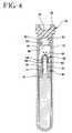
- FIG. 4is a cross-sectional view similar to Figs. 2 and 3, but showing the device at an early stage during centrifugation.
- FIG. 5is a cross-sectional view similar to Fig. 4, but showing the device at a later stage during centrifugation.
- FIG. 6is a cross-sectional view similar to Fig. 5, but showing the device upon completion of centrifugation, and with the respective phases of blood separated.
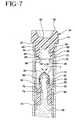
- FIG. 7is an enlarged cross-sectional view of portions of the device adjacent the seal plug during the early stages of centrifugation, as shown in Fig. 4.
- FIG. 8is an enlarged cross-sectional view of portions of the device adjacent the seal plug at a later stage during centrifugation, as shown in Fig. 5.
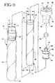
- FIG. 9is an exploded perspective view of the device.
- FIGS. 1 to 9The preferred apparatus of the present invention is illustrated in FIGS. 1 to 9, wherein device 10 comprises a tube 12 , an elastomeric liner 22 , a closure 34 , and a seal plug assembly 64 .
- Device 10includes rigid plastic tube 12 having an open top 14 , a closed bottom 16 and a cylindrical sidewall 18 .
- Sidewall 18defines a constant inside diameter "a" along a major portion of its length.
- Device 10further includes an elastomeric liner 22 having an open top 24 , a closed bottom 26 and a tubular sidewall 28 .
- Side wall 28in an unbiased condition, defines an inside diameter "c” and an outside diameter “d” along a major portion of the length of liner 22 .
- Outside diameter "d”is less than inside diameter "a" of sidewall 18 on tube 12 , and is approximately equal to or slightly less than inside diameter "b" of rim 20 .
- Liner 22is characterized by an outwardly directed flange 30 adjacent open top 24 . Portions of flange 30 immediately adjacent open top 24 are cylindrically generated and define an outside diameter "e”.
- portions of flange 30 spaced from open top 24taper to outside diameter "d" which exists elsewhere on sidewall 28 .
- Diameter “e” of flange 30is greater than inside diameter "b" of rim 20 on tube 12 , and is approximately equal to or slightly less than inside diameter "a” existing at locations on tube 12 between rim 20 and open top 14 thereof.
- portions of liner 22 below flange 30can be slid through rim 20 on tube 12 .
- flange 30can be slid into portions of tube 12 between rim 20 and open top 14 .
- flange 30will interfere with rim 20 and will prevent liner 22 from sliding entirely past rim 20 .
- the length of liner 22is selected to ensure that closed bottom 26 of liner 22 is spaced slightly from closed bottom 16 of tube 12 when flange 30 of liner 22 engages rim 20 of tube 12 .
- vent slits 31enable an escape of air from the space between liner 22 and tube 12 during assembly, and thereby facilitates the complete insertion of liner 22 into tube 12 .
- Device 10further includes a tube closure that can be pierced by a needle cannula and that will reseal itself after removal of the needle cannula.
- Tube closure 34includes a top end 36 and a bottom end 38 .
- Top end 36 of tube closure 34is characterized by a central recess 40 which defines a target area for piercing by a needle cannula.
- a radially aligned tube end seat 42is defined between top and bottom ends 36 and 38 and faces toward bottom end 38 .
- Tube end seat 42defines an outside diameter that exceeds the outside diameter of tube 12 .
- tube end seat 42can be sealingly engaged against open top end 14 of tube 12 .
- a liner end seat 44is defined on tube closure 34 at a distance below tube end seat 42 to ensure that liner end seat 44 is substantially adjacent open top end 24 of liner 22 when tube end seat 42 is adjacent to open top end 14 of tube 12 .
- Portions of tube stopper 46 adjacent liner end seat 44define a diameter approximately equal to inside diameter "a" of tube 12 .
- Portions of tube stopper 46 closer to tube end seat 42define a larger diameter. Consequently, tube stopper 46 is compressed during insertion into tube 14 for achieving a tight sealing engagement.
- a liner stopper 48extends from liner end seat 44 to bottom end 38 of tube closure 34 .
- Liner stopper 48has a cylindrical outer surface along most of its length with an outside diameter slightly greater than inside diameter "c" of liner 22 . However, portions of liner stopper 48 adjacent bottom end 38 are chamfered to a diameter that is less than inside diameter "c" of liner 22 . The chamfered bottom end of liner stopper 48 facilitates the inward compression required to urge liner stopper 48 of tube closure 34 into open top end 24 of liner 22 .
- Liner stopper 48is further characterized by at least one axially extending vent groove 50 to permit venting of gas from liner 22 during insertion of tube closure 34 .
- Tube closure 34is further characterized by a plug recess 52 extending axially into bottom end 38 .
- the entrance to plug recess 52is defined by a plurality of circumferentially spaced flexible release walls 54 that have inner surfaces 56 generated as part of a single cylinder with a diameter "f".
- Each flexible release wall 54further includes a chamfered surface 58 extending from the cylindrically generated surface 56 to the bottom end 38 of tube closure 34 .
- Flexible release walls 54each also include a radially aligned plug-gripping surface 60 facing into plug recess 52 .
- the top central portion of plug recess 52is defined by downwardly pointing conical surface 62 .
- Device 10further includes a seal plug assembly 64 which comprises a generally tubular hard plastic shell 66 and an elastomeric septum 68 .
- the components of seal plug assembly 64are formed from materials to exhibit a combined density less than the density of the red blood cells, but greater than the density of the serum.
- Shell 66includes a top end 70 , a bottom end 72 and a central passage 74 extending continuously between the ends.
- Annular sealing ribs 76 and 78extend outwardly from shell 66 at locations near bottom end 72 .
- Annular sealing ribs 76 and 78define diameters approximately equal to inside diameter "c" of liner 22 .
- Shell 66further includes an outwardly projecting annular septum flange 80 substantially adjacent top end 70 and an annular closure engagement wall 82 between sealing flange 78 and septum flange 80 .
- Closure engagement wall 82defines an outside diameter that is substantially equal to the inside diameter of plug recess 52 of tube closure 34 .
- a cylindrical wall 84extends between closure engagement wall 82 and sealing flange 78 .
- Cylindrical wall 84defines an outside diameter approximately equal to the inside diameter "f" defined by flexible release walls 54 of tube closure 34 .
- cylindrical wall 84defines a length approximately equal to the axial length of cylindrically generated portions 56 of flexible release walls 54 .
- Elastomeric septum 68is molded unitarily from a rupturable elastomeric material such as Kraton copolymer, a urethane or PVC.
- Septum 68includes a bottom 86 , a generally cylindrical side wall 88 extending upwardly from bottom wall 86 and an initially conically convex top wall 90 extending upwardly from cylindrical side wall 88 .
- a shell recess 92extends centrally into bottom 86 of septum 68 .
- Shell recess 92includes a small diameter entry having a length substantially equal to the axial distance between septum flange 80 and closure engaging flange 82 on shell 66 .
- Shell recess 92further includes a large diameter portion that dimensionally conforms to axial and diametric dimensions of septum flange 80 on shell 66 .
- Device 10is assembled by slidably inserting liner 22 into shell 12 until flange 30 of liner 22 is seated against annular rim 20 of tube 12 .
- outside diameter "d" of cylindrical side wall 28 of liner 22is less than inside diameter "a” of cylindrical side wall 18 of tube 12 . Accordingly, an annular space will exist between liner 22 and tube 12 at locations between annular rim 20 of tube 12 and closed bottom 16 thereof.
- Seal plug 64then may be assembled by mounting elastomeric septum 68 over top 70 of shell 66 . More particularly, septum flange 80 is forcibly urged into shell recess 92 in open bottom 86 of septum 68 . Small diameter portions of recess 92 will resiliently engage around portions of shell 66 between septum flange 80 and closure engagement flange 82 . Seal plug assembly 64 then is urged into plug recess 52 in bottom end 38 of tube closure 34 . This will require an initial outward stretching of portions of tube closure 34 adjacent bottom end 38 . However, tube closure 34 will resiliently return toward an undeflected condition with flexible release walls 54 engaged around cylindrical wall 84 between closure engagement flange 82 and annular sealing flange 78 . Additionally, conical surface 62 in shell recess 52 of tube closure 34 will cause convexly conical top wall 90 of septum 68 to deflect into concave configuration in nested engagement with conical surface 62 .
- closure 34 and seal plug 64then is inserted into open top end 14 of tube 12 . Sufficient insertion causes annular sealing flanges 76 and 78 of shell 66 to sealingly engage in liner 22 .
- Liner end seat 44will seat substantially adjacent open top 24 of liner 22 .
- Tube stopper 46will compress into tight sealing engagement with inner circumferential portions of tube 12 between liner 22 and open top 14 of tube 12 . Insertion of tube closure 43 into tube 12 will terminate when tube end seat 42 seats against open top 14 of tube 12 .
- a needle cannula 94is used to insert a sample of blood into device 10 . More particularly, as shown most clearly in Fig. 3 , needle cannula 94 is urged centrally into recess 40 at top end 36 of tube closure 34 . Continued advancement of needle cannula 94 will cause a rupturing of conical top wall 90 of septum 68 . An appropriate volume of blood 96 then is delivered from needle cannula 94 into liner 22 . Portions of tube closure 34 adjacent recess 40 will self-seal upon removal of needle cannula 94 . However, conical top wall 90 of septum 68 will remain with a defect.
- Device 10 with blood 96 thereinthen is placed in a centrifuge which places a centrifugal load on device 10 .
- the centrifugal loaddeflects flexible release walls 54 sufficiently downwardly to permit separation of seal plug assembly 64 from tube closure 34 .
- the centrifugal loadcauses an outward deflection of tubular sidewall 28 of elastomeric tube liner 22 .
- This outward deflection of liner 22permits seal plug 64 to move toward closed bottoms 26 and 16 of liner 22 and tube 12 respectively.
- Airwill be trapped in passage 74 of shell 66 approximately when bottom end 72 of shell 66 contacts blood 96 . This trapped air could restrict further downward movement of seal plug 64 .
- the defect in septum 68 caused by needle cannula 94defines a path through which trapped air may escape passage 74 .
- seal plug 64is permitted to sink into blood 96 .
- the centrifugal load created by the centrifugealso separates serum from red blood cells in blood 96 .
- red blood cellsunder the action of the centrifugal load, migrate around seal plug assembly 64 and toward closed bottom 26 of liner 22 .
- the less dense serum of blood 96will flow between shell 66 and outwardly deformed portions of elastomeric liner 22 as shown schematically in Fig. 5 .
- Seal plug 64will stabilize at a position in liner 22 between the red blood cells and the serum of blood 96 . This stabilized position is attributable to the formation of seal plug 66 and septum 68 from materials that will give seal plug 64 a density less than the density of the red blood cells, but greater than the density of the serum. After a specified time, the centrifuge will be stopped. The absence of the centrifugal load will cause side wall 28 of elastomeric liner 22 to resiliently return toward an undeformed condition and into tight sealing engagement with annular sealing flanges 76 and 78 of shell 66 . Thus, red blood cells 98 will be sealed between seal plug 64 and closed bottom 26 of liner 22 , while serum 100 will lie between seal plug 64 and closure 34 .
- Liner 22is compatible with most of the numerous additives used in sample collection tubes such as citrates, silicates. EDTA and the like that are used to condition the fluid sample either to facilitate or retard clotting, or to preserve the fluid sample for a particular analysis. It is within the purview of this invention that one or more additives may be used in the present invention for particular applications.
- additivesused in sample collection tubes such as citrates, silicates. EDTA and the like that are used to condition the fluid sample either to facilitate or retard clotting, or to preserve the fluid sample for a particular analysis. It is within the purview of this invention that one or more additives may be used in the present invention for particular applications.
- the separator of the present inventionwas made as follows: The three components of the separator, a liner, a septum, a seal plug were made by injection molding.
- the linerwas made from DuPont Dow Engage® 8400 polyolefin elastomer with a flexural modulus of 22 MPa.
- the septumwas made from GLS Dynaflex® 2712 (Dynaflex is a trademark of and manufactured by GLS Corp., Cory, Ill.), with a specific gravity of 0.889.
- the seal plugwas made from Bayer Lustran® 348 ABS with a specific gravity of 1.06.
- the separator of the present inventionwas made as follows: The two components of the separator, the liner was injection molded from DuPont Dow Engage® 8411 polyolefin elastomer with a flexural modulus of 29 MPa and the seal plug was injection molded from Bayer Lustran® 348 with a specific gravity of 1.06.
- the separator of the present inventionwas made as follows: The three components of the separator, the liner was injection molded from DuPont Dow Engage® 8411 polyolefin elastomer with a flexural modulus of 29 MPa and the septum was made from a Kraton® elastomer and the seal plug injection molded from Bayer Lustram® 348 with a specific gravity of 1.06.
Landscapes
- Health & Medical Sciences (AREA)
- Life Sciences & Earth Sciences (AREA)
- Engineering & Computer Science (AREA)
- Biomedical Technology (AREA)
- Hematology (AREA)
- General Health & Medical Sciences (AREA)
- Physics & Mathematics (AREA)
- Biophysics (AREA)
- Pathology (AREA)
- Molecular Biology (AREA)
- Heart & Thoracic Surgery (AREA)
- Medical Informatics (AREA)
- Surgery (AREA)
- Animal Behavior & Ethology (AREA)
- Public Health (AREA)
- Veterinary Medicine (AREA)
- Chemical & Material Sciences (AREA)
- Chemical Kinetics & Catalysis (AREA)
- Manufacturing & Machinery (AREA)
- Analytical Chemistry (AREA)
- Clinical Laboratory Science (AREA)
- Ecology (AREA)
- Urology & Nephrology (AREA)
- Food Science & Technology (AREA)
- Medicinal Chemistry (AREA)
- Biochemistry (AREA)
- General Physics & Mathematics (AREA)
- Immunology (AREA)
- Centrifugal Separators (AREA)
- Investigating Or Analysing Biological Materials (AREA)
- Measurement Of The Respiration, Hearing Ability, Form, And Blood Characteristics Of Living Organisms (AREA)
- Sampling And Sample Adjustment (AREA)
Abstract

Description
This invention relates to a device and method for separating heavier and lighterfractions of a fluid sample. More particularly, this invention relates to a device andmethod for collecting and transporting fluid samples whereby the device and fluid sampleare subjected to centrifugation to cause separation of the heavier fraction from the lighterfraction of the fluid sample.
Diagnostic tests may require separation of a patient's whole blood sample intocomponents, such as serum or plasma, the lighter phase component, and red blood cells,the heavier phase component. Samples of whole blood are typically collected byvenipuncture through a cannula or needle attached to a syringe or an evacuated collectiontube. Separation of the blood into serum or plasma and red blood cells is thenaccomplished by rotation of the syringe or tube in a centrifuge. Such arrangements use abarrier for moving into an area adjacent the two phases of the sample being separated to maintain the components separated for subsequent examination of the individualcomponents.
A variety of devices have been used in collection devices to divide the areabetween the heavier and lighter phases of a fluid sample.
The most widely used device includes thixotropic gel materials such as polyestergels in a tube. The present polyester gel serum separation tubes require specialmanufacturing equipment to prepare the gel and to fill the tubes. Moreover, the shelf-lifeof the product is limited in that overtime globules may be released from the gel mass.These globules have a specific gravity that is less than the separated serum and may floatin the serum and may clog the measuring instruments, such as the instrument probes usedduring clinical examination of the sample collected in the tube. Such clogging can lead toconsiderable downtime for the instrument to remove the clog.
No commercially available gel is completely chemically inert to all analytes. Ifcertain drugs are present in the blood sample when it is taken, there can be an adversechemical reaction with the gel interface.
Therefore, a need exists for a separator device that (i) is easily used to separate ablood sample; (ii) is independent of temperature during storage and shipping; (iii) isstable to radiation sterilization; (iv) employs the benefits of a thixotropic gel barrier yetavoids the many disadvantages of placing a gel in contact with the separated bloodcomponents; (v) minimizes cross contamination of the heavier and lighter phases of thesample during centrifugation; (vi) minimizes adhesion of the lower and higher densitymaterials against the separator device; (vii) can be used with standard sampling equipment; (viii) is able to move into position to form a barrier in less time thanconventional methods and devices; and (ix) is able to provide a clearer specimen with lesscell contamination than conventional methods and devices.
The present invention is a method and assembly for separating a fluid sample intoa higher specific gravity phase and a lower specific gravity phase. Desirably, theassembly of the present invention comprises a plurality of constituents. Preferably, theassembly comprises a container, a liner and a composite element.
The container may be a conventional tube having a closed bottom, an opened topand a rigid cylindrical wall extending therebetween. The tube may include an inwardlydirected rim near the open top.
The assembly further comprises a liner having a closed bottom, an open top and atubular side wall. The liner is positioned in the tube such that the closed bottom of theliner is near the closed bottom of the tube. The liner, in an unbiased condition, is cross-sectionallydimensioned along most of its length to lie in spaced relationship to the tube.However, the liner may include an outwardly directed flange substantially adjacent thetop of the liner. The flange may be dimensioned for engagement against the rim of thetube to position the liner longitudinally within the tube.
Preferably, the liner comprises a qualitative stiffness that may be characterized bya non-dimensional stiffness coefficient, S* and expressed as follows:S* =EOD-D aρw D2 where E is the modulus of elasticity, OD is the thickness defined by the outside diameter,D is the seal diameter, a is the applied acceleration, and ρw is the density of water. Thestiffness coefficient is about .003 to about 190.
Preferably, the liner has a thickness of about 1.0mm to about 2.5mm, a modulus ofelasticity of about 13.8 MPa to about 69 MPa.
Preferably, the assembly of the present invention will function under load createdby an applied acceleration of about 300g to about 3000g.
Preferably, the liner deforms due to hydrostatic pressure under applied accelerationand returns to its initial state upon removal of the acceleration, thereby forming a seal byconstricting the seal plug which is positioned in a target density region between the higherdensity portion and the lower density portion of a fluid sample.
The assembly further includes a tube closure that is sealingly engageable in theopen top of the tube. The tube closure may include a tube end seat having an outsidediameter at least equal to the outside diameter of the tube for disposition substantiallyadjacent the open top of the tube. The tube closure may include a tube stopperdimensioned for sealed engagement in portions of the tube between the top of the tubeand the top of the liner. The tube closure may further include a liner stopper dimensionedfor sealing engagement in the open top of the liner.
A plug recess extends into the bottom end of the tube closure. The entry to theplug recess may have a plurality of inwardly extending circumferentially spaced flexiblewalls.
Preferably, the composite element comprises a seal plug. The seal plug may be asingle constituent or a plurality of constituents and comprises a specific density at a targetdensity range as defined by separable fluid components densities. The seal plug maymigrate freely when under an applied acceleration to settle at a location in the fluidsample in the target density region and thereby become a barrier at a desired levelbetween the components of the fluid sample after the acceleration is removed.
Preferably, the seal plug has an aggregate specific gravity of about 1.028 to about1.09. Most preferably, the seal plug has an aggregate specific gravity so that it will restafter centrifugal force, between the heavier and lighter phases of a blood sample.
The seal plug preferably has an overall density between the densities of two phasesof a blood sample. The seal plug comprises a hard plastic shell having opposed first andsecond ends and an aperture extending between the ends. Outer circumferential portionsof the hard plastic shell in proximity to the first end are dimensioned and configured forreleasable engagement within the plug recess of the tube closure. Outer circumferentialportions of the hard plastic shell in proximity to the second end are dimensioned forsealing engagement by the unbiased tube liner. The seal plug further includes anelastomeric septum that is securely mounted around the first end of the hard plastic shellto provide a pierceable barrier extending across the central passage through the shell.
Preferably, the seal plug comprises an overall specific gravity at a target specificgravity of σt. The target specific gravity is that required to separate a fluid sample intotwo phases.
In use, a fluid sample enters the assembly by a needle. The needle penetrates theclosure and through the elastomeric septum on the seal plug for delivering a fluid sampleinto the liner. The needle is withdrawn from the assembly and the assembly is subjectedto centrifugation. Forces exerted by the centrifuge cause the seal plug to separate fromthe tube closure and cause the liner to expand outwardly against the tube. Centrifugalforces then cause the seal plug to move through the expanded liner and toward the closedbottom of the tube. Sufficient movement will cause the seal plug to contact the fluid. Airtrapped in the passage through the hard plastic liner and between the fluid and theelastomeric septum could create a buoyancy that might prevent further sinking of the sealplug into the fluid. However, the trapped air will be vented through a defect in theseptum, such as the defect caused by the needle cannula. This venting of air permitsfurther movement of the seal plug into the fluid. Simultaneously, the phases of the fluidwill be separating such that the heavier phase component of the fluid will concentratecloser to the closed bottom, and such that the lighter phase component of the fluid will becloser to the open top. The seal plug will move primarily through the lighter phasecomponent and toward the heavier phase component of the fluid.
The centrifuge may be stopped after the seal plug stabilizes between the separatephases of the fluid. Upon termination of the centrifugal load, the liner will resilientlyreturn toward its unexpanded condition and will sealingly engage outer circumferentialregions of the seal plug. As a result, the phases of the fluid sample are isolated from one another by the seal plug and may be separated for subsequent analysis.
When the fluid sample is blood, the higher specific gravity portion that containsthe cellular components is between the separator and the bottom of the container aftercentrifugation. The lower specific gravity portion that contains the cell-free serumfraction or plasma is between the top surface of the separator and the top of the containerafter centrifugation.
Therefore, at the final position of the separator after centrifugation, the separator isable to substantially eliminate the presence of red blood cells in the lower specific gravityportion and the lower specific gravity is substantially free of cellular contamination.
The assembly of the present invention is advantageous over existing separationproducts that use gel. In particular, the assembly of the present invention will notinterfere with analytes as compared to gels that may interfere with analytes. Anotherattribute of the present invention is that the assembly of the present invention will notinterfere with therapeutic drug monitoring analytes.
Most notably, is that the time to separate a fluid sample into separate densities isachieved in substantially less time with the assembly of the present invention ascompared to assemblies that use gel.
Another notable advantage of the present invention is that fluid specimens are notsubjected to low density gel residuals that are at times available in products that use gel.
A further attribute of the present invention is that there is no interference withinstrument probes.
Another attribute of the present invention is that samples for blood banking testsare more acceptable than when a gel separator is used.
Another attribute of the present invention is that only the substantially cell-freeserum fraction of a blood sample is exposed to the top surface of the separator, thusproviding practitioners with a clean sample.
Additionally, the assembly of the present invention does not require any additionalsteps or treatment by a medical practitioner whereby a blood or fluid sample is drawn inthe standard fashion, using standard sampling equipment.
FIG. 1 is a perspective view of a blood collection tube device in accordance withthe subject invention.
FIG. 2 is a cross-sectional view taken along line 2-2 in Fig. 1.
FIG. 3 is a cross-sectional view similar to Fig. 2, but showing the device afterinsertion of a blood sample therein by a needle cannula.
FIG. 4 is a cross-sectional view similar to Figs. 2 and 3, but showing the device atan early stage during centrifugation.
FIG. 5 is a cross-sectional view similar to Fig. 4, but showing the device at a laterstage during centrifugation.
FIG. 6 is a cross-sectional view similar to Fig. 5, but showing the device uponcompletion of centrifugation, and with the respective phases of blood separated.
FIG. 7 is an enlarged cross-sectional view of portions of the device adjacent theseal plug during the early stages of centrifugation, as shown in Fig. 4.
FIG. 8 is an enlarged cross-sectional view of portions of the device adjacent theseal plug at a later stage during centrifugation, as shown in Fig. 5.
FIG. 9 is an exploded perspective view of the device.
The present invention may be embodied in other specific forms and is not limitedto any specific embodiments described in detail, which are merely exemplary. Variousother modifications will be apparent to and readily made by those skilled in the artwithout departing from the scope and spirit of the invention. The scope of the inventionwill be measured by the appended claims and their equivalents.
The preferred apparatus of the present invention is illustrated in FIGS. 1 to 9,wherein device10 comprises a tube12, an elastomeric liner22, a closure34, and a sealplug assembly64.
Device10 includes rigid plastic tube12 having an open top14, a closed bottom16and a cylindrical sidewall18. Sidewall18 defines a constant inside diameter "a" along amajor portion of its length.
Device10 further includes an elastomeric liner22 having an open top24, a closedbottom26 and a tubular sidewall28. Side wall28, in an unbiased condition, defines aninside diameter "c" and an outside diameter "d" along a major portion of the length ofliner22. Outside diameter "d" is less than inside diameter "a" of sidewall18 on tube12,and is approximately equal to or slightly less than inside diameter "b" of rim20. Liner22is characterized by an outwardly directed flange30 adjacent open top24. Portions offlange30 immediately adjacent open top24 are cylindrically generated and define anoutside diameter "e". However, portions of flange30 spaced from open top24 taper tooutside diameter "d" which exists elsewhere on sidewall28. Diameter "e" of flange30 isgreater than inside diameter "b" of rim20 on tube12, and is approximately equal to orslightly less than inside diameter "a" existing at locations on tube12 between rim20 andopen top14 thereof. With these relative diametrical dimensions, portions of liner22below flange30 can be slid through rim20 on tube12. Additionally, flange30 can beslid into portions of tube12 between rim20 and open top14. However, flange30 willinterfere with rim20 and will prevent liner22 from sliding entirely past rim20. Thelength of liner22 is selected to ensure that closed bottom26 of liner22 is spaced slightlyfrom closed bottom16 of tube12 when flange30 of liner22 engages rim20 of tube12.
The outer circumferential surface of flange30 is provided with a plurality ofcircumferentially spaced, axially aligned vent slits31. Vent slits31 enable an escape of air from the space between liner22 and tube12 during assembly, and thereby facilitatesthe complete insertion of liner22 into tube12.
Device10 further includes a tube closure that can be pierced by a needle cannulaand that will reseal itself after removal of the needle cannula. Tube closure34 includes atop end36 and a bottom end38. Top end36 of tube closure34 is characterized by acentral recess40 which defines a target area for piercing by a needle cannula. A radiallyaligned tube end seat42 is defined between top and bottom ends36 and38 and facestoward bottom end38. Tube end seat42 defines an outside diameter that exceeds theoutside diameter of tube12. Thus, tube end seat42 can be sealingly engaged againstopen top end14 of tube12.
A liner end seat44 is defined on tube closure34 at a distance below tube end seat42 to ensure that liner end seat44 is substantially adjacent open top end24 of liner22when tube end seat42 is adjacent to open top end14 of tube12. Portions of tube stopper46 adjacent liner end seat44 define a diameter approximately equal to inside diameter "a"of tube12. Portions of tube stopper46 closer to tube end seat42 define a larger diameter.Consequently, tube stopper46 is compressed during insertion into tube14 for achieving atight sealing engagement.
A liner stopper48 extends from liner end seat44 to bottom end38 of tube closure34. Liner stopper48 has a cylindrical outer surface along most of its length with anoutside diameter slightly greater than inside diameter "c" of liner22. However, portionsof liner stopper48 adjacent bottom end38 are chamfered to a diameter that is less thaninside diameter "c" of liner22. The chamfered bottom end of liner stopper48 facilitatesthe inward compression required to urge liner stopper48 of tube closure34 into open top end24 of liner22. Liner stopper48 is further characterized by at least one axiallyextending vent groove50 to permit venting of gas from liner22 during insertion of tubeclosure34.
Tube closure34 is further characterized by a plug recess52 extending axially intobottom end38. The entrance to plug recess52 is defined by a plurality ofcircumferentially spaced flexible release walls54 that have inner surfaces56 generated aspart of a single cylinder with a diameter "f". Each flexible release wall54 furtherincludes a chamfered surface58 extending from the cylindrically generated surface56 tothe bottom end38 of tube closure34. Flexible release walls54 each also include aradially aligned plug-gripping surface60 facing into plug recess52. The top centralportion of plug recess52 is defined by downwardly pointing conical surface62.
Device10 further includes a seal plug assembly64 which comprises a generallytubular hard plastic shell66 and an elastomeric septum68. The components of seal plugassembly64 are formed from materials to exhibit a combined density less than the densityof the red blood cells, but greater than the density of the serum. Shell66 includes a topend70, a bottom end72 and a central passage74 extending continuously between theends. Annular sealing ribs76 and78 extend outwardly from shell66 at locations nearbottom end72. Annular sealing ribs76 and78 define diameters approximately equal toinside diameter "c" of liner22. Shell66 further includes an outwardly projecting annularseptum flange80 substantially adjacent top end70 and an annular closure engagementwall 82 between sealing flange78 and septum flange80. Closure engagement wall82defines an outside diameter that is substantially equal to the inside diameter of plug recess52 of tube closure34. A cylindrical wall84 extends between closure engagement wall82and sealing flange78. Cylindrical wall84 defines an outside diameter approximately equal to the inside diameter "f" defined by flexible release walls54 of tube closure34.Additionally, cylindrical wall84 defines a length approximately equal to the axial lengthof cylindrically generated portions56 of flexible release walls54.
Elastomeric septum68 is molded unitarily from a rupturable elastomeric materialsuch as Kraton copolymer, a urethane or PVC. Septum68 includes a bottom86, agenerally cylindrical side wall88 extending upwardly from bottom wall86 and aninitially conically convex top wall90 extending upwardly from cylindrical side wall88.A shell recess92 extends centrally into bottom86 of septum68. Shell recess92 includesa small diameter entry having a length substantially equal to the axial distance betweenseptum flange80 and closure engaging flange82 on shell66. Shell recess92 furtherincludes a large diameter portion that dimensionally conforms to axial and diametricdimensions of septum flange80 on shell66.
Device10 is assembled by slidably inserting liner22 into shell12 until flange30of liner22 is seated against annular rim20 of tube12. As noted above, outside diameter"d" of cylindrical side wall28 of liner22 is less than inside diameter "a" of cylindricalside wall18 of tube12. Accordingly, an annular space will exist between liner22 andtube12 at locations between annular rim20 of tube12 and closed bottom16 thereof.
Seal plug64 then may be assembled by mounting elastomeric septum68 over top70 of shell66. More particularly, septum flange80 is forcibly urged into shell recess92in open bottom86 of septum68. Small diameter portions of recess92 will resilientlyengage around portions of shell66 between septum flange80 and closure engagementflange82. Seal plug assembly64 then is urged into plug recess52 in bottom end38 oftube closure34. This will require an initial outward stretching of portions of tube closure34 adjacent bottom end38. However, tube closure34 will resiliently return toward anundeflected condition with flexible release walls54 engaged around cylindrical wall84between closure engagement flange82 and annular sealing flange78. Additionally,conical surface62 in shell recess52 of tube closure34 will cause convexly conical topwall90 of septum68 to deflect into concave configuration in nested engagement withconical surface62.
The assembly of closure34 and seal plug64 then is inserted into open top end14of tube12. Sufficient insertion causes annular sealing flanges76 and78 of shell66 tosealingly engage in liner22. Liner end seat44 will seat substantially adjacent open top24 of liner22. Tube stopper46 will compress into tight sealing engagement with innercircumferential portions of tube12 between liner22 and open top14 of tube12.Insertion of tube closure43 into tube12 will terminate when tube end seat42 seatsagainst open top14 of tube12.
A needle cannula94 is used to insert a sample of blood into device10. Moreparticularly, as shown most clearly inFig. 3, needle cannula94 is urged centrally intorecess40 at top end36 of tube closure34. Continued advancement of needle cannula94will cause a rupturing of conical top wall90 of septum68. An appropriate volume ofblood96 then is delivered from needle cannula94 into liner22. Portions of tube closure34 adjacent recess40 will self-seal upon removal of needle cannula94. However, conicaltop wall90 of septum68 will remain with a defect.
Device10 with blood96 therein then is placed in a centrifuge which places acentrifugal load on device10. The centrifugal load deflects flexible release walls54sufficiently downwardly to permit separation of seal plug assembly64 from tube closure34. Simultaneously, the centrifugal load causes an outward deflection of tubular sidewall28 of elastomeric tube liner22. This outward deflection of liner22 permits seal plug64to move toward closed bottoms26 and16 of liner22 and tube12 respectively. Air willbe trapped in passage74 of shell66 approximately when bottom end72 of shell66contacts blood96. This trapped air could restrict further downward movement of sealplug64. However, the defect in septum68 caused by needle cannula94 defines a paththrough which trapped air may escape passage74. Thus, seal plug64 is permitted to sinkinto blood96.
The centrifugal load created by the centrifuge also separates serum from red bloodcells in blood96. Thus, red blood cells, under the action of the centrifugal load, migratearound seal plug assembly64 and toward closed bottom26 of liner22. Simultaneously,the less dense serum of blood96 will flow between shell66 and outwardly deformedportions of elastomeric liner22 as shown schematically inFig. 5.
Seal plug64 will stabilize at a position in liner22 between the red blood cells andthe serum of blood96. This stabilized position is attributable to the formation of sealplug66 and septum68 from materials that will give seal plug64 a density less than thedensity of the red blood cells, but greater than the density of the serum. After a specifiedtime, the centrifuge will be stopped. The absence of the centrifugal load will cause sidewall28 of elastomeric liner22 to resiliently return toward an undeformed condition andinto tight sealing engagement with annular sealing flanges76 and78 of shell66. Thus,red blood cells98 will be sealed between seal plug64 and closed bottom26 of liner22,while serum100 will lie between seal plug64 and closure34.
Liner22 is compatible with most of the numerous additives used in samplecollection tubes such as citrates, silicates. EDTA and the like that are used to conditionthe fluid sample either to facilitate or retard clotting, or to preserve the fluid sample for aparticular analysis. It is within the purview of this invention that one or more additivesmay be used in the present invention for particular applications.
The separator of the present invention was made as follows: The threecomponents of the separator, a liner, a septum, a seal plug were made by injectionmolding. The liner was made from DuPont Dow Engage® 8400 polyolefin elastomerwith a flexural modulus of 22 MPa. The septum was made from GLS Dynaflex® 2712(Dynaflex is a trademark of and manufactured by GLS Corp., Cory, Ill.), with a specificgravity of 0.889. The seal plug was made from Bayer Lustran® 348 ABS with a specificgravity of 1.06.
The separator of the present invention was made as follows: The two componentsof the separator, the liner was injection molded from DuPont Dow Engage® 8411polyolefin elastomer with a flexural modulus of 29 MPa and the seal plug was injectionmolded from Bayer Lustran® 348 with a specific gravity of 1.06.
The separator of the present invention was made as follows: The threecomponents of the separator, the liner was injection molded from DuPont Dow Engage®8411 polyolefin elastomer with a flexural modulus of 29 MPa and the septum was made from a Kraton® elastomer and the seal plug injection molded from Bayer Lustram® 348with a specific gravity of 1.06.
Claims (10)
- A tube device for separating blood into first and second phases of differentrespective densities, said device comprising:a substantially rigid tube having an open top and a closed bottom;an elastomeric liner having an open top and a closed bottom and positioned in saidtube such that at least portions of said liner are spaced inwardly from said tube, said linerbeing resiliently expandable such that at least portions of said liner are engageable withsaid tube in response to loads imposed on said liner;a tube closure in said open top of said tube; anda seal plug sealingly engaged by said elastomeric liner in an unexpanded conditionof said liner, said seal plug further being releasably engaged with said tube closure forseparation from said tube closure in response to a selected axial load, said seal plughaving a density between the respective densities of the phases of a liquid sample.
- The device of Claim 1 wherein the top end of the liner is configured forsealing engagement with inner circumferential surface regions of said tube.
- The device of Claim 2 wherein a portion of said tube closure is sealinglyengaged in said open top of said liner and urges said open top of said liner into sealingengagement with said inner circumferential surface regions of said tube.
- The device of Claim 3 wherein the inner circumferential surface regions ofsaid tube engaged by said liner include an annular inwardly extending rim on said tube.
- The device of Claim 4 wherein the top of said liner includes an outwardlyextending flange engageable with said rim of said tube for limiting insertion of said linerinto said tube.
- The device of Claim 1 wherein the tube closure includes a plug recessdimensioned for releasably receiving at least a portion of said seal plug.
- The device of Claim 6 wherein the tube closure includes a plurality ofcircumferentially spaced flexible release walls for releasably engaging a portion of saidseal plug, said flexible release walls being resiliently deflectable toward said closedbottom of said liner in response to a selected load on said device.
- The device of Claim 7 wherein the seal plug includes an annular closureengaging flange disposed in said plug recess of said tube closure and releasably engagedwith said flexible release walls of said tube closure.
- The device of Claim 1 wherein said seal plug includes a substantially rigidgenerally tubular shell having opposed top and bottom ends and a passage extendingtherebetween, a rupturable septum sealingly covering portions of said passage adjacentsaid top end, said septum defining an air vent hole in response to rupturing of said septumby a needle cannula for permitting venting of air through said septum to enable said sealplug to sink into said blood.
- The device of Claim 1 wherein the seal plug includes a substantially rigidportion having a plurality of annular sealing flanges dimensioned for sealing engagementby said elastomeric liner in an unbiased condition of said liner.
Applications Claiming Priority (2)
| Application Number | Priority Date | Filing Date | Title |
|---|---|---|---|
| US11092798P | 1998-12-05 | 1998-12-05 | |
| US110927P | 1998-12-05 |
Publications (2)
| Publication Number | Publication Date |
|---|---|
| EP1005910A2true EP1005910A2 (en) | 2000-06-07 |
| EP1005910A3 EP1005910A3 (en) | 2002-06-12 |
Family
ID=22335695
Family Applications (1)
| Application Number | Title | Priority Date | Filing Date |
|---|---|---|---|
| EP99124315AWithdrawnEP1005910A3 (en) | 1998-12-05 | 1999-12-06 | Centrifuge tube with cylindrically symmetric separation element, liner and cap |
Country Status (3)
| Country | Link |
|---|---|
| US (1) | US6516953B1 (en) |
| EP (1) | EP1005910A3 (en) |
| JP (1) | JP4398032B2 (en) |
Cited By (52)
| Publication number | Priority date | Publication date | Assignee | Title |
|---|---|---|---|---|
| WO2002002237A1 (en)* | 2000-06-30 | 2002-01-10 | Beckman Coulter, Inc. | Removable conformal liners for centrifuge containers |
| WO2002078848A3 (en)* | 2001-03-30 | 2002-12-27 | Greiner Bio One Gmbh | Holding device, particularly for body fluids, comprising a separating device, and a separating device therefor |
| WO2003092894A3 (en)* | 2002-05-03 | 2004-03-25 | Hanuman Llc | Method and apparatus for isolating platelets from blood |
| WO2004030826A2 (en) | 2002-10-03 | 2004-04-15 | Battelle Memorial Institute | Buffy coat separator float system and method |
| WO2004031770A1 (en) | 2002-10-03 | 2004-04-15 | Battelle Memorial Institute | Buffy coat tube and float system and method |
| US7179391B2 (en) | 2002-05-24 | 2007-02-20 | Biomet Manufacturing Corp. | Apparatus and method for separating and concentrating fluids containing multiple components |
| US7374678B2 (en) | 2002-05-24 | 2008-05-20 | Biomet Biologics, Inc. | Apparatus and method for separating and concentrating fluids containing multiple components |
| US7708152B2 (en) | 2005-02-07 | 2010-05-04 | Hanuman Llc | Method and apparatus for preparing platelet rich plasma and concentrates thereof |
| US7806276B2 (en) | 2007-04-12 | 2010-10-05 | Hanuman, Llc | Buoy suspension fractionation system |
| US7832566B2 (en) | 2002-05-24 | 2010-11-16 | Biomet Biologics, Llc | Method and apparatus for separating and concentrating a component from a multi-component material including macroparticles |
| US7845499B2 (en) | 2002-05-24 | 2010-12-07 | Biomet Biologics, Llc | Apparatus and method for separating and concentrating fluids containing multiple components |
| EP2277625A1 (en) | 2004-01-23 | 2011-01-26 | Greiner Bio-One GmbH | Retaining device for blood, body fluids, tissue samples or tissue cultures |
| US8012077B2 (en) | 2008-05-23 | 2011-09-06 | Biomet Biologics, Llc | Blood separating device |
| WO2012026970A3 (en)* | 2010-08-21 | 2012-05-24 | Chapman John R | Centrifuge and separation vessel therefore |
| US8187475B2 (en) | 2009-03-06 | 2012-05-29 | Biomet Biologics, Llc | Method and apparatus for producing autologous thrombin |
| US8309343B2 (en) | 2008-12-01 | 2012-11-13 | Baxter International Inc. | Apparatus and method for processing biological material |
| US8313954B2 (en) | 2009-04-03 | 2012-11-20 | Biomet Biologics, Llc | All-in-one means of separating blood components |
| US8328024B2 (en) | 2007-04-12 | 2012-12-11 | Hanuman, Llc | Buoy suspension fractionation system |
| US8337711B2 (en) | 2008-02-29 | 2012-12-25 | Biomet Biologics, Llc | System and process for separating a material |
| US8394342B2 (en) | 2008-07-21 | 2013-03-12 | Becton, Dickinson And Company | Density phase separation device |
| US8567609B2 (en) | 2006-05-25 | 2013-10-29 | Biomet Biologics, Llc | Apparatus and method for separating and concentrating fluids containing multiple components |
| US8591391B2 (en) | 2010-04-12 | 2013-11-26 | Biomet Biologics, Llc | Method and apparatus for separating a material |
| US8747781B2 (en) | 2008-07-21 | 2014-06-10 | Becton, Dickinson And Company | Density phase separation device |
| US8794452B2 (en) | 2009-05-15 | 2014-08-05 | Becton, Dickinson And Company | Density phase separation device |
| US9011800B2 (en) | 2009-07-16 | 2015-04-21 | Biomet Biologics, Llc | Method and apparatus for separating biological materials |
| CN104588140A (en)* | 2008-07-21 | 2015-05-06 | 贝克顿·迪金森公司 | Density phase separation device |
| EP2928374A4 (en)* | 2012-12-05 | 2017-04-12 | Theranos, Inc. | Systems, devices, and methods for bodily fluid sample collection and transport |
| US9636062B2 (en) | 2012-09-06 | 2017-05-02 | Theranos, Inc. | Systems, devices, and methods for bodily fluid sample collection |
| US9642956B2 (en) | 2012-08-27 | 2017-05-09 | Biomet Biologics, Llc | Apparatus and method for separating and concentrating fluids containing multiple components |
| US9694359B2 (en) | 2014-11-13 | 2017-07-04 | Becton, Dickinson And Company | Mechanical separator for a biological fluid |
| US9701728B2 (en) | 2008-02-27 | 2017-07-11 | Biomet Biologics, Llc | Methods and compositions for delivering interleukin-1 receptor antagonist |
| US9713810B2 (en) | 2015-03-30 | 2017-07-25 | Biomet Biologics, Llc | Cell washing plunger using centrifugal force |
| US9757721B2 (en) | 2015-05-11 | 2017-09-12 | Biomet Biologics, Llc | Cell washing plunger using centrifugal force |
| US9877674B2 (en) | 2012-09-06 | 2018-01-30 | Theranos Ip Company, Llc | Systems, devices, and methods for bodily fluid sample collection |
| CN107684774A (en)* | 2017-09-29 | 2018-02-13 | 广州市雷德生物科技有限公司 | A kind of filter |
| US9895418B2 (en) | 2013-03-15 | 2018-02-20 | Biomet Biologics, Llc | Treatment of peripheral vascular disease using protein solutions |
| US9897589B2 (en) | 2002-05-24 | 2018-02-20 | Biomet Biologics, Llc | Apparatus and method for separating and concentrating fluids containing multiple components |
| US9950035B2 (en) | 2013-03-15 | 2018-04-24 | Biomet Biologics, Llc | Methods and non-immunogenic compositions for treating inflammatory disorders |
| US10143725B2 (en) | 2013-03-15 | 2018-12-04 | Biomet Biologics, Llc | Treatment of pain using protein solutions |
| US10208095B2 (en) | 2013-03-15 | 2019-02-19 | Biomet Manufacturing, Llc | Methods for making cytokine compositions from tissues using non-centrifugal methods |
| US10244973B2 (en) | 2012-12-05 | 2019-04-02 | Theranos Ip Company, Llc | Systems, devices, and methods for bodily fluid sample transport |
| US10248765B1 (en) | 2012-12-05 | 2019-04-02 | Theranos Ip Company, Llc | Systems, devices, and methods for bodily fluid sample collection, transport, and handling |
| US10371606B2 (en) | 2015-07-21 | 2019-08-06 | Theraos IP Company, LLC | Bodily fluid sample collection and transport |
| US10576130B2 (en) | 2013-03-15 | 2020-03-03 | Biomet Manufacturing, Llc | Treatment of collagen defects using protein solutions |
| US10856791B2 (en) | 2014-03-12 | 2020-12-08 | Labrador Diagnostics Llc | Systems, devices, and methods for bodily fluid sample collection |
| CN112806993A (en)* | 2021-01-11 | 2021-05-18 | 德阳市人民医院 | Blood sampling test tube subassembly |
| EP3847965A1 (en)* | 2015-12-11 | 2021-07-14 | Babson Diagnostics, Inc. | Specimen container and method for separating serum or plasma from whole blood |
| US11278884B2 (en) | 2014-10-28 | 2022-03-22 | Arteriocyte Medical Systems, Inc. | Centrifuge tube comprising a floating buoy, and methods for using the same |
| CN115475412A (en)* | 2022-10-20 | 2022-12-16 | 深圳瑞亚力集团有限公司 | Purification method for oil generated by liquid drops |
| US12025629B2 (en) | 2022-04-06 | 2024-07-02 | Babson Diagnostics, Inc. | Automated centrifuge loader |
| US12050052B1 (en) | 2021-08-06 | 2024-07-30 | Babson Diagnostics, Inc. | Refrigerated carrier device for biological samples |
| US12174207B2 (en) | 2016-11-14 | 2024-12-24 | Babson Diagnostics, Inc. | Blood sample preparation device and methods |
Families Citing this family (44)
| Publication number | Priority date | Publication date | Assignee | Title |
|---|---|---|---|---|
| US7947236B2 (en) | 1999-12-03 | 2011-05-24 | Becton, Dickinson And Company | Device for separating components of a fluid sample |
| US6354452B1 (en)* | 2000-07-25 | 2002-03-12 | Becton, Dickinson And Company | Collection container assembly |
| US7992725B2 (en) | 2002-05-03 | 2011-08-09 | Biomet Biologics, Llc | Buoy suspension fractionation system |
| CA2484876C (en) | 2002-05-13 | 2011-11-22 | Becton, Dickinson And Company | Protease inhibitor sample collection system |
| EP1549224A1 (en) | 2002-10-10 | 2005-07-06 | Becton Dickinson and Company | Sample collection system with caspase inhibitor |
| WO2005014173A1 (en)* | 2003-08-05 | 2005-02-17 | Becton, Dickinson And Company | Device and methods for collection of biological fluidsample and treatment of selected components |
| US20050124965A1 (en)* | 2003-12-08 | 2005-06-09 | Becton, Dickinson And Company | Phosphatase inhibitor sample collection system |
| DK1848473T3 (en)* | 2005-02-07 | 2013-09-02 | Hanuman Llc | Plasma concentrations device |
| EP2666493B1 (en)* | 2005-02-07 | 2020-09-23 | Hanuman LLC | Platelet rich plasma concentrate apparatus |
| US7866485B2 (en) | 2005-02-07 | 2011-01-11 | Hanuman, Llc | Apparatus and method for preparing platelet rich plasma and concentrates thereof |
| US7694828B2 (en) | 2005-04-27 | 2010-04-13 | Biomet Manufacturing Corp. | Method and apparatus for producing autologous clotting components |
| US20070003449A1 (en)* | 2005-06-10 | 2007-01-04 | Mehdi Hatamian | Valve for facilitating and maintaining fluid separation |
| US20070131612A1 (en)* | 2005-10-27 | 2007-06-14 | Duffy Neil F Jr | Cell separation method and apparatus |
| US8048678B2 (en) | 2005-10-27 | 2011-11-01 | Ecw Therapeutics, Inc. | Cell separation method and apparatus |
| EP2024742B1 (en)* | 2006-05-22 | 2020-03-04 | 3M Innovative Properties Company | System and method for preparing samples |
| JP2011502545A (en)* | 2007-11-20 | 2011-01-27 | スリーエム イノベイティブ プロパティズ カンパニー | Sample preparation container and method |
| US8647574B2 (en)* | 2007-11-20 | 2014-02-11 | 3M Innovative Properties Company | Sample preparation container and method |
| US8569072B2 (en)* | 2007-11-20 | 2013-10-29 | 3M Innovative Properties Company | Sample preparation container and method |
| CN101909757B (en)* | 2007-11-20 | 2013-07-24 | 3M创新有限公司 | Sample preparation for environmental sampling |
| EP3616618B1 (en)* | 2008-03-05 | 2022-11-30 | Becton, Dickinson and Company | Capillary action collection device |
| US20100093551A1 (en)* | 2008-10-09 | 2010-04-15 | Decision Biomarkers, Inc. | Liquid Transfer and Filter System |
| US8177072B2 (en)* | 2008-12-04 | 2012-05-15 | Thermogenesis Corp. | Apparatus and method for separating and isolating components of a biological fluid |
| US9272083B2 (en) | 2009-05-29 | 2016-03-01 | Endocellutions, Inc. | Apparatus and methods for aspirating and separating components of different densities from a physiological fluid containing cells |
| KR101069877B1 (en) | 2009-10-28 | 2011-10-05 | 임기표 | Kit of centrifuge separation and methods for centrifuging using the same |
| US20130017130A1 (en)* | 2010-03-30 | 2013-01-17 | Haubert Thomas D | Buffy coat separator float systems and methods |
| EP2553114A1 (en)* | 2010-03-30 | 2013-02-06 | Battelle Memorial Institute | Buffy coat separator float systems and methods |
| US9028425B2 (en)* | 2010-07-15 | 2015-05-12 | Becton, Dickinson And Company | Vented blood sampling device |
| MX347230B (en) | 2011-03-04 | 2017-04-20 | Becton Dickinson Co | Blood collection device containing lysophospholipase inhibitor. |
| WO2013045695A2 (en) | 2011-09-30 | 2013-04-04 | Pz Cormay S.A. | Method for delivering a sample of body fluid to an analysing system, a syringe designed for use therein and a kit comprising such a syringe |
| US9427707B2 (en) | 2012-08-10 | 2016-08-30 | Jean I. Montagu | Filtering blood |
| PL400953A1 (en) | 2012-09-27 | 2014-03-31 | Scope Fluidics Spółka Z Ograniczoną Odpowiedzialnością | Microfluidic system and method for providing a body fluid sample for the analysis system using the microfluidic system |
| US10603665B2 (en) | 2013-01-29 | 2020-03-31 | Endocellutions, Inc. | Cell concentration devices and methods that include an insert defining a lumen and a cannula assembly |
| US9550028B2 (en) | 2014-05-06 | 2017-01-24 | Biomet Biologics, LLC. | Single step desiccating bead-in-syringe concentrating device |
| US20160136639A1 (en)* | 2014-11-13 | 2016-05-19 | Becton, Dickinson And Company | Mechanical Separator for a Biological Fluid |
| FR3036954B1 (en)* | 2015-06-03 | 2017-07-14 | Imv Tech | STRAW FOR PRESERVING A PREDETERMINED DOSE OF LIQUID-BASED SUBSTANCE, AND INJECTION DEVICE AND METHOD FOR CARRYING OUT THE SAME |
| WO2017041205A1 (en)* | 2015-09-07 | 2017-03-16 | Mann+Hummel Gmbh | Liner with seal for rotor of centrifugal separator |
| PL237582B1 (en)* | 2015-09-15 | 2021-05-04 | Spark Tech Spolka Z Ograniczona Odpowiedzialnoscia | Insert for a centrifuge container, in particular a test tube, for separating fractions with the desired density range by density gradient centrifugation, and a centrifuge container containing this insert |
| US20200330982A1 (en)* | 2016-03-17 | 2020-10-22 | Amin KAZEMZADEH | Long-term storage and proportional dispensing device |
| JP6989609B2 (en) | 2017-01-25 | 2022-01-05 | ヤンタイ・アウスビオ・ラボラトリーズ・カンパニー・リミテッド | Equipment and methods for automated sample processing for diagnostic purposes |
| PL421074A1 (en) | 2017-03-31 | 2018-10-08 | Pz Cormay Spółka Akcyjna | Microflow system |
| DE102017108933B4 (en)* | 2017-04-26 | 2018-12-06 | Sarstedt Aktiengesellschaft & Co.Kg | separating body |
| EP3927447B1 (en) | 2018-11-30 | 2025-07-23 | Hans-Werner Heinrich | Separation system, apparatus, and methods of use |
| US11135580B1 (en)* | 2020-07-15 | 2021-10-05 | Prp Technologies Inc | Device, kit and methods for creating platelet rich plasma |
| CA3182142A1 (en)* | 2020-07-15 | 2022-01-20 | Prp Technologies, Inc. | Device, kit and methods for creating platelet rich plasma |
Family Cites Families (25)
| Publication number | Priority date | Publication date | Assignee | Title |
|---|---|---|---|---|
| US3849072A (en) | 1972-04-25 | 1974-11-19 | Becton Dickinson Co | Plasma separator |
| US3779383A (en) | 1972-04-25 | 1973-12-18 | Becton Dickinson Co | Sealed assembly for separation of blood components and method |
| US3897343A (en) | 1974-02-27 | 1975-07-29 | Becton Dickinson Co | Plasma separator-hydrostatic pressure type |
| US4083788A (en) | 1975-11-19 | 1978-04-11 | Ferrara Louis T | Blood serum-isolation device |
| US4088582A (en) | 1976-01-16 | 1978-05-09 | Sherwood Medical Industries Inc. | Blood phase separation means |
| AT381466B (en) | 1977-03-16 | 1986-10-27 | Ballies Uwe | SEPARATING TUBES FOR CENTRIFUGAL SEPARATION |
| US4131549A (en) | 1977-05-16 | 1978-12-26 | Ferrara Louis T | Serum separation device |
| US4257886A (en) | 1979-01-18 | 1981-03-24 | Becton, Dickinson And Company | Apparatus for the separation of blood components |
| AU542204B2 (en) | 1979-03-23 | 1985-02-14 | Terumo Corp. | Separating blood |
| EP0039898B1 (en) | 1980-05-08 | 1984-08-22 | Terumo Corporation | Apparatus for separating blood |
| DE3101733C2 (en) | 1981-01-21 | 1982-10-14 | Uwe Dr.Med. 2300 Kiel Ballies | Separating element in a separating tube for centrifugal separation |
| US4417981A (en) | 1981-05-04 | 1983-11-29 | Becton, Dickinson And Company | Blood phase separator device |
| US4443345A (en) | 1982-06-28 | 1984-04-17 | Wells John R | Serum preparator |
| SE448323B (en) | 1985-08-27 | 1987-02-09 | Ersson Nils Olof | PROCEDURE AND PROCEDURE TO SEPARATE SERUM OR PLASMA FROM BLOOD |
| US4818386A (en) | 1987-10-08 | 1989-04-04 | Becton, Dickinson And Company | Device for separating the components of a liquid sample having higher and lower specific gravities |
| US4877520A (en) | 1987-10-08 | 1989-10-31 | Becton, Dickinson And Company | Device for separating the components of a liquid sample having higher and lower specific gravities |
| US5269927A (en) | 1991-05-29 | 1993-12-14 | Sherwood Medical Company | Separation device for use in blood collection tubes |
| JPH06222055A (en) | 1993-01-22 | 1994-08-12 | Niigata Kako Kk | Component separating member for liquid sample |
| US5389265A (en) | 1993-06-02 | 1995-02-14 | E. I. Du Pont De Nemours And Company | Phase-separation tube |
| JPH07103969A (en) | 1993-08-13 | 1995-04-21 | Niigata Kako Kk | Blood separation member and blood collecting tube for blood separation |
| US5455009A (en) | 1993-09-14 | 1995-10-03 | Becton, Dickinson And Company | Blood collection assembly including clot-accelerating plastic insert |
| US5575778A (en)* | 1994-09-21 | 1996-11-19 | B. Braun Melsungen Ag | Blood-taking device |
| US5585007A (en) | 1994-12-07 | 1996-12-17 | Plasmaseal Corporation | Plasma concentrate and tissue sealant methods and apparatuses for making concentrated plasma and/or tissue sealant |
| US5632905A (en) | 1995-08-07 | 1997-05-27 | Haynes; John L. | Method and apparatus for separating formed and unformed components |
| AT409725B (en) | 1997-05-12 | 2002-10-25 | Greiner & Soehne C A | SEPARATOR |
- 1999
- 1999-12-02USUS09/452,981patent/US6516953B1/ennot_activeExpired - Lifetime
- 1999-12-06JPJP34694799Apatent/JP4398032B2/ennot_activeExpired - Lifetime
- 1999-12-06EPEP99124315Apatent/EP1005910A3/ennot_activeWithdrawn
Cited By (121)
| Publication number | Priority date | Publication date | Assignee | Title |
|---|---|---|---|---|
| WO2002002237A1 (en)* | 2000-06-30 | 2002-01-10 | Beckman Coulter, Inc. | Removable conformal liners for centrifuge containers |
| US7188734B2 (en) | 2001-03-30 | 2007-03-13 | Greiner Bio-One Gmbh | Holding device, particularly for bodily fluids, comprising a separating device, and a separating device therefor |
| WO2002078848A3 (en)* | 2001-03-30 | 2002-12-27 | Greiner Bio One Gmbh | Holding device, particularly for body fluids, comprising a separating device, and a separating device therefor |
| US7837884B2 (en) | 2002-05-03 | 2010-11-23 | Hanuman, Llc | Methods and apparatus for isolating platelets from blood |
| US7470371B2 (en) | 2002-05-03 | 2008-12-30 | Hanuman Llc | Methods and apparatus for isolating platelets from blood |
| WO2003092894A3 (en)* | 2002-05-03 | 2004-03-25 | Hanuman Llc | Method and apparatus for isolating platelets from blood |
| US8187477B2 (en) | 2002-05-03 | 2012-05-29 | Hanuman, Llc | Methods and apparatus for isolating platelets from blood |
| US7223346B2 (en) | 2002-05-03 | 2007-05-29 | Hanuman Llc | Methods and apparatus for isolating platelets from blood |
| US8950586B2 (en) | 2002-05-03 | 2015-02-10 | Hanuman Llc | Methods and apparatus for isolating platelets from blood |
| US7374678B2 (en) | 2002-05-24 | 2008-05-20 | Biomet Biologics, Inc. | Apparatus and method for separating and concentrating fluids containing multiple components |
| US10393728B2 (en) | 2002-05-24 | 2019-08-27 | Biomet Biologics, Llc | Apparatus and method for separating and concentrating fluids containing multiple components |
| US10183042B2 (en) | 2002-05-24 | 2019-01-22 | Biomet Manufacturing, Llc | Apparatus and method for separating and concentrating fluids containing multiple components |
| US7914689B2 (en) | 2002-05-24 | 2011-03-29 | Biomet Biologics, Llc | Apparatus and method for separating and concentrating fluids containing multiple components |
| US8603346B2 (en) | 2002-05-24 | 2013-12-10 | Biomet Biologics, Llc | Apparatus and method for separating and concentrating fluids containing multiple components |
| US9897589B2 (en) | 2002-05-24 | 2018-02-20 | Biomet Biologics, Llc | Apparatus and method for separating and concentrating fluids containing multiple components |
| US7780860B2 (en) | 2002-05-24 | 2010-08-24 | Biomet Biologics, Llc | Apparatus and method for separating and concentrating fluids containing multiple components |
| US7179391B2 (en) | 2002-05-24 | 2007-02-20 | Biomet Manufacturing Corp. | Apparatus and method for separating and concentrating fluids containing multiple components |
| US7832566B2 (en) | 2002-05-24 | 2010-11-16 | Biomet Biologics, Llc | Method and apparatus for separating and concentrating a component from a multi-component material including macroparticles |
| US8808551B2 (en) | 2002-05-24 | 2014-08-19 | Biomet Biologics, Llc | Apparatus and method for separating and concentrating fluids containing multiple components |
| US8062534B2 (en) | 2002-05-24 | 2011-11-22 | Biomet Biologics, Llc | Apparatus and method for separating and concentrating fluids containing multiple components |
| US8048321B2 (en) | 2002-05-24 | 2011-11-01 | Biomet Biologics, Llc | Apparatus and method for separating and concentrating fluids containing multiple components |
| US7845499B2 (en) | 2002-05-24 | 2010-12-07 | Biomet Biologics, Llc | Apparatus and method for separating and concentrating fluids containing multiple components |
| AU2003277223B8 (en)* | 2002-10-03 | 2009-11-19 | Battelle Memorial Institute | Buffy coat separator float system and method |
| EP1552270A4 (en)* | 2002-10-03 | 2009-12-30 | Battelle Memorial Institute | Buffy coat separator float system and method |
| WO2004030826A2 (en) | 2002-10-03 | 2004-04-15 | Battelle Memorial Institute | Buffy coat separator float system and method |
| WO2004031770A1 (en) | 2002-10-03 | 2004-04-15 | Battelle Memorial Institute | Buffy coat tube and float system and method |
| EP2559991A1 (en)* | 2002-10-03 | 2013-02-20 | Battelle Memorial Institute | Buffy coat separator float system and method |
| EP1546720A4 (en)* | 2002-10-03 | 2009-10-28 | Battelle Memorial Institute | Buffy coat tube and float system and method |
| EP2458381A3 (en)* | 2002-10-03 | 2012-07-25 | Battelle Memorial Institute | Buffy coat float |
| AU2003277223B2 (en)* | 2002-10-03 | 2009-11-05 | Battelle Memorial Institute | Buffy coat separator float system and method |
| EP2277625A1 (en) | 2004-01-23 | 2011-01-26 | Greiner Bio-One GmbH | Retaining device for blood, body fluids, tissue samples or tissue cultures |
| US8448800B2 (en) | 2004-01-23 | 2013-05-28 | Greiner Bio-One Gmbh | Method for the assembly of a cap with a receptacle |
| US7987995B2 (en) | 2005-02-07 | 2011-08-02 | Hanuman, Llc | Method and apparatus for preparing platelet rich plasma and concentrates thereof |
| US7708152B2 (en) | 2005-02-07 | 2010-05-04 | Hanuman Llc | Method and apparatus for preparing platelet rich plasma and concentrates thereof |
| US8133389B2 (en) | 2005-02-07 | 2012-03-13 | Hanuman, Llc | Method and apparatus for preparing platelet rich plasma and concentrates thereof |
| US8567609B2 (en) | 2006-05-25 | 2013-10-29 | Biomet Biologics, Llc | Apparatus and method for separating and concentrating fluids containing multiple components |
| US8596470B2 (en) | 2007-04-12 | 2013-12-03 | Hanuman, Llc | Buoy fractionation system |
| US8119013B2 (en) | 2007-04-12 | 2012-02-21 | Hanuman, Llc | Method of separating a selected component from a multiple component material |
| US7806276B2 (en) | 2007-04-12 | 2010-10-05 | Hanuman, Llc | Buoy suspension fractionation system |
| US8328024B2 (en) | 2007-04-12 | 2012-12-11 | Hanuman, Llc | Buoy suspension fractionation system |
| US9649579B2 (en) | 2007-04-12 | 2017-05-16 | Hanuman Llc | Buoy suspension fractionation system |
| US10400017B2 (en) | 2008-02-27 | 2019-09-03 | Biomet Biologics, Llc | Methods and compositions for delivering interleukin-1 receptor antagonist |
| US9701728B2 (en) | 2008-02-27 | 2017-07-11 | Biomet Biologics, Llc | Methods and compositions for delivering interleukin-1 receptor antagonist |
| US11725031B2 (en) | 2008-02-27 | 2023-08-15 | Biomet Manufacturing, Llc | Methods and compositions for delivering interleukin-1 receptor antagonist |
| US8337711B2 (en) | 2008-02-29 | 2012-12-25 | Biomet Biologics, Llc | System and process for separating a material |
| US8801586B2 (en) | 2008-02-29 | 2014-08-12 | Biomet Biologics, Llc | System and process for separating a material |
| US9719063B2 (en) | 2008-02-29 | 2017-08-01 | Biomet Biologics, Llc | System and process for separating a material |
| US8012077B2 (en) | 2008-05-23 | 2011-09-06 | Biomet Biologics, Llc | Blood separating device |
| US9714890B2 (en) | 2008-07-21 | 2017-07-25 | Becton, Dickinson And Company | Density phase separation device |
| CN104588140B (en)* | 2008-07-21 | 2016-06-29 | 贝克顿·迪金森公司 | Density phase separation device |
| US8394342B2 (en) | 2008-07-21 | 2013-03-12 | Becton, Dickinson And Company | Density phase separation device |
| US9700886B2 (en) | 2008-07-21 | 2017-07-11 | Becton, Dickinson And Company | Density phase separation device |
| CN104588140A (en)* | 2008-07-21 | 2015-05-06 | 贝克顿·迪金森公司 | Density phase separation device |
| US9933344B2 (en) | 2008-07-21 | 2018-04-03 | Becton, Dickinson And Company | Density phase separation device |
| US10350591B2 (en) | 2008-07-21 | 2019-07-16 | Becton, Dickinson And Company | Density phase separation device |
| US9452427B2 (en) | 2008-07-21 | 2016-09-27 | Becton, Dickinson And Company | Density phase separation device |
| US8747781B2 (en) | 2008-07-21 | 2014-06-10 | Becton, Dickinson And Company | Density phase separation device |
| US9333445B2 (en) | 2008-07-21 | 2016-05-10 | Becton, Dickinson And Company | Density phase separation device |
| US9339741B2 (en) | 2008-07-21 | 2016-05-17 | Becton, Dickinson And Company | Density phase separation device |
| US9423327B2 (en) | 2008-12-01 | 2016-08-23 | Baxalta GmbH | Apparatus and method for processing biological material |
| US9182328B2 (en) | 2008-12-01 | 2015-11-10 | Baxalta Incorporated | Apparatus and method for processing biological material |
| US9176038B2 (en) | 2008-12-01 | 2015-11-03 | Baxalta Incorporated | Apparatus and method for processing biological material |
| US8309343B2 (en) | 2008-12-01 | 2012-11-13 | Baxter International Inc. | Apparatus and method for processing biological material |
| US9097631B2 (en) | 2008-12-01 | 2015-08-04 | Baxter International Inc. | Apparatus and method for processing biological material |
| US8187475B2 (en) | 2009-03-06 | 2012-05-29 | Biomet Biologics, Llc | Method and apparatus for producing autologous thrombin |
| US8783470B2 (en) | 2009-03-06 | 2014-07-22 | Biomet Biologics, Llc | Method and apparatus for producing autologous thrombin |
| US8992862B2 (en) | 2009-04-03 | 2015-03-31 | Biomet Biologics, Llc | All-in-one means of separating blood components |
| US8313954B2 (en) | 2009-04-03 | 2012-11-20 | Biomet Biologics, Llc | All-in-one means of separating blood components |
| US9919308B2 (en) | 2009-05-15 | 2018-03-20 | Becton, Dickinson And Company | Density phase separation device |
| US8794452B2 (en) | 2009-05-15 | 2014-08-05 | Becton, Dickinson And Company | Density phase separation device |
| US8998000B2 (en) | 2009-05-15 | 2015-04-07 | Becton, Dickinson And Company | Density phase separation device |
| US11351535B2 (en) | 2009-05-15 | 2022-06-07 | Becton, Dickinson And Company | Density phase separation device |
| US9079123B2 (en) | 2009-05-15 | 2015-07-14 | Becton, Dickinson And Company | Density phase separation device |
| US9731290B2 (en) | 2009-05-15 | 2017-08-15 | Becton, Dickinson And Company | Density phase separation device |
| US10807088B2 (en) | 2009-05-15 | 2020-10-20 | Becton, Dickinson And Company | Density phase separation device |
| US9802189B2 (en) | 2009-05-15 | 2017-10-31 | Becton, Dickinson And Company | Density phase separation device |
| US9364828B2 (en) | 2009-05-15 | 2016-06-14 | Becton, Dickinson And Company | Density phase separation device |
| US10456782B2 (en) | 2009-05-15 | 2019-10-29 | Becton, Dickinson And Company | Density phase separation device |
| US10413898B2 (en) | 2009-05-15 | 2019-09-17 | Becton, Dickinson And Company | Density phase separation device |
| US12090476B2 (en) | 2009-05-15 | 2024-09-17 | Becton, Dickinson And Company | Density phase separation device |
| US9919307B2 (en) | 2009-05-15 | 2018-03-20 | Becton, Dickinson And Company | Density phase separation device |
| US10343157B2 (en) | 2009-05-15 | 2019-07-09 | Becton, Dickinson And Company | Density phase separation device |
| US9919309B2 (en) | 2009-05-15 | 2018-03-20 | Becton, Dickinson And Company | Density phase separation device |
| US10376879B2 (en) | 2009-05-15 | 2019-08-13 | Becton, Dickinson And Company | Density phase separation device |
| US11786895B2 (en) | 2009-05-15 | 2023-10-17 | Becton, Dickinson And Company | Density phase separation device |
| US9011800B2 (en) | 2009-07-16 | 2015-04-21 | Biomet Biologics, Llc | Method and apparatus for separating biological materials |
| US8591391B2 (en) | 2010-04-12 | 2013-11-26 | Biomet Biologics, Llc | Method and apparatus for separating a material |
| WO2012026970A3 (en)* | 2010-08-21 | 2012-05-24 | Chapman John R | Centrifuge and separation vessel therefore |
| US9642956B2 (en) | 2012-08-27 | 2017-05-09 | Biomet Biologics, Llc | Apparatus and method for separating and concentrating fluids containing multiple components |
| US9877674B2 (en) | 2012-09-06 | 2018-01-30 | Theranos Ip Company, Llc | Systems, devices, and methods for bodily fluid sample collection |
| US10842424B2 (en) | 2012-09-06 | 2020-11-24 | Labrador Diagnostics Llc | Systems, devices, and methods for bodily fluid sample collection |
| US9636062B2 (en) | 2012-09-06 | 2017-05-02 | Theranos, Inc. | Systems, devices, and methods for bodily fluid sample collection |
| US10248765B1 (en) | 2012-12-05 | 2019-04-02 | Theranos Ip Company, Llc | Systems, devices, and methods for bodily fluid sample collection, transport, and handling |
| US10244973B2 (en) | 2012-12-05 | 2019-04-02 | Theranos Ip Company, Llc | Systems, devices, and methods for bodily fluid sample transport |
| EP2928374A4 (en)* | 2012-12-05 | 2017-04-12 | Theranos, Inc. | Systems, devices, and methods for bodily fluid sample collection and transport |
| US9895418B2 (en) | 2013-03-15 | 2018-02-20 | Biomet Biologics, Llc | Treatment of peripheral vascular disease using protein solutions |
| US9950035B2 (en) | 2013-03-15 | 2018-04-24 | Biomet Biologics, Llc | Methods and non-immunogenic compositions for treating inflammatory disorders |
| US10441634B2 (en) | 2013-03-15 | 2019-10-15 | Biomet Biologics, Llc | Treatment of peripheral vascular disease using protein solutions |
| US11957733B2 (en) | 2013-03-15 | 2024-04-16 | Biomet Manufacturing, Llc | Treatment of collagen defects using protein solutions |
| US10576130B2 (en) | 2013-03-15 | 2020-03-03 | Biomet Manufacturing, Llc | Treatment of collagen defects using protein solutions |
| US10143725B2 (en) | 2013-03-15 | 2018-12-04 | Biomet Biologics, Llc | Treatment of pain using protein solutions |
| US10208095B2 (en) | 2013-03-15 | 2019-02-19 | Biomet Manufacturing, Llc | Methods for making cytokine compositions from tissues using non-centrifugal methods |
| US10856791B2 (en) | 2014-03-12 | 2020-12-08 | Labrador Diagnostics Llc | Systems, devices, and methods for bodily fluid sample collection |
| US11759777B2 (en) | 2014-10-28 | 2023-09-19 | Arteriocyte Medical Systems, Inc. | Centrifuge tube comprising a floating buoy, and methods for using the same |
| US11278884B2 (en) | 2014-10-28 | 2022-03-22 | Arteriocyte Medical Systems, Inc. | Centrifuge tube comprising a floating buoy, and methods for using the same |
| US9694359B2 (en) | 2014-11-13 | 2017-07-04 | Becton, Dickinson And Company | Mechanical separator for a biological fluid |
| US9713810B2 (en) | 2015-03-30 | 2017-07-25 | Biomet Biologics, Llc | Cell washing plunger using centrifugal force |
| US9757721B2 (en) | 2015-05-11 | 2017-09-12 | Biomet Biologics, Llc | Cell washing plunger using centrifugal force |
| US11305275B2 (en) | 2015-07-21 | 2022-04-19 | Labrador Diagnostics Llc | Bodily fluid sample collection and transport |
| US10371606B2 (en) | 2015-07-21 | 2019-08-06 | Theraos IP Company, LLC | Bodily fluid sample collection and transport |
| US12059676B1 (en) | 2015-12-11 | 2024-08-13 | Babson Diagnostics, Inc. | Device and method for testing serum and plasma separated from blood cells in whole blood samples |
| US11697114B2 (en) | 2015-12-11 | 2023-07-11 | Babson Diagnostics, Inc. | Centrifugation method separating serum or plasma from whole blood using a specimen container having a cap to retain blood cells |
| EP3847965A1 (en)* | 2015-12-11 | 2021-07-14 | Babson Diagnostics, Inc. | Specimen container and method for separating serum or plasma from whole blood |
| US12174207B2 (en) | 2016-11-14 | 2024-12-24 | Babson Diagnostics, Inc. | Blood sample preparation device and methods |
| CN107684774B (en)* | 2017-09-29 | 2023-09-22 | 广州市雷德生物科技有限公司 | Filtering device |
| CN107684774A (en)* | 2017-09-29 | 2018-02-13 | 广州市雷德生物科技有限公司 | A kind of filter |
| CN112806993A (en)* | 2021-01-11 | 2021-05-18 | 德阳市人民医院 | Blood sampling test tube subassembly |
| US12050052B1 (en) | 2021-08-06 | 2024-07-30 | Babson Diagnostics, Inc. | Refrigerated carrier device for biological samples |
| US12025629B2 (en) | 2022-04-06 | 2024-07-02 | Babson Diagnostics, Inc. | Automated centrifuge loader |
| CN115475412B (en)* | 2022-10-20 | 2024-02-02 | 深圳瑞亚力集团有限公司 | Purification method for liquid drop generated oil |
| CN115475412A (en)* | 2022-10-20 | 2022-12-16 | 深圳瑞亚力集团有限公司 | Purification method for oil generated by liquid drops |
Also Published As
| Publication number | Publication date |
|---|---|
| US6516953B1 (en) | 2003-02-11 |
| JP2000189406A (en) | 2000-07-11 |
| JP4398032B2 (en) | 2010-01-13 |
| EP1005910A3 (en) | 2002-06-12 |
Similar Documents
| Publication | Publication Date | Title |
|---|---|---|
| US6516953B1 (en) | Device for separating components of a fluid sample | |
| EP1005909B1 (en) | Centrifuge tube with round separation element, liner and cap | |
| EP1014088B1 (en) | Device and method for separating components of a fluid sample | |
| US7153477B2 (en) | Device and method for separating components of a fluid sample | |
| US6479298B1 (en) | Device and method for separating components of a fluid sample | |
| US6409528B1 (en) | Device and method for collecting, preparation and stabilizing a sample | |
| EP1106253B1 (en) | Device for separating components of a fluid sample | |
| US6471069B2 (en) | Device for separating components of a fluid sample | |
| US6793892B1 (en) | Device and method for separating components of a fluid sample | |
| JP5385383B2 (en) | Density phase separator | |
| US8747781B2 (en) | Density phase separation device | |
| US20020132367A1 (en) | Device and method for separating components of a fluid sample |
Legal Events
| Date | Code | Title | Description |
|---|---|---|---|
| PUAI | Public reference made under article 153(3) epc to a published international application that has entered the european phase | Free format text:ORIGINAL CODE: 0009012 | |
| AK | Designated contracting states | Kind code of ref document:A2 Designated state(s):AT BE CH CY DE DK ES FI FR GB GR IE IT LI LU MC NL PT SE | |
| AX | Request for extension of the european patent | Free format text:AL;LT;LV;MK;RO;SI | |
| PUAL | Search report despatched | Free format text:ORIGINAL CODE: 0009013 | |
| RIC1 | Information provided on ipc code assigned before grant | Free format text:7B 01L 3/14 A, 7G 01N 33/49 B | |
| AK | Designated contracting states | Kind code of ref document:A3 Designated state(s):AT BE CH CY DE DK ES FI FR GB GR IE IT LI LU MC NL PT SE | |
| AX | Request for extension of the european patent | Free format text:AL;LT;LV;MK;RO;SI | |
| 17P | Request for examination filed | Effective date:20020713 | |
| AKX | Designation fees paid | Designated state(s):DE FR GB IT | |
| 17Q | First examination report despatched | Effective date:20030408 | |
| STAA | Information on the status of an ep patent application or granted ep patent | Free format text:STATUS: THE APPLICATION IS DEEMED TO BE WITHDRAWN | |
| 18D | Application deemed to be withdrawn | Effective date:20031021 |