EP1004332B1 - Stationary exercise device - Google Patents
Stationary exercise deviceDownload PDFInfo
- Publication number
- EP1004332B1 EP1004332B1EP00104023AEP00104023AEP1004332B1EP 1004332 B1EP1004332 B1EP 1004332B1EP 00104023 AEP00104023 AEP 00104023AEP 00104023 AEP00104023 AEP 00104023AEP 1004332 B1EP1004332 B1EP 1004332B1
- Authority
- EP
- European Patent Office
- Prior art keywords
- foot
- frame
- guide
- exercise device
- rear end
- Prior art date
- Legal status (The legal status is an assumption and is not a legal conclusion. Google has not performed a legal analysis and makes no representation as to the accuracy of the status listed.)
- Expired - Lifetime
Links
- 230000033001locomotionEffects0.000claimsdescription25
- 230000008878couplingEffects0.000claimsdescription8
- 238000010168coupling processMethods0.000claimsdescription8
- 238000005859coupling reactionMethods0.000claimsdescription8
- 238000006073displacement reactionMethods0.000claimsdescription2
- 210000002683footAnatomy0.000description96
- 230000001429stepping effectEffects0.000description13
- 230000007246mechanismEffects0.000description12
- 230000009194climbingEffects0.000description8
- 238000010276constructionMethods0.000description7
- 230000000712assemblyEffects0.000description6
- 238000000429assemblyMethods0.000description6
- 239000007787solidSubstances0.000description5
- 230000008901benefitEffects0.000description4
- 230000008859changeEffects0.000description4
- 210000002414legAnatomy0.000description4
- 238000000034methodMethods0.000description3
- 210000003205muscleAnatomy0.000description3
- 230000014759maintenance of locationEffects0.000description2
- 239000000463materialSubstances0.000description2
- 230000003287optical effectEffects0.000description2
- 230000002787reinforcementEffects0.000description2
- 230000035939shockEffects0.000description2
- 238000010561standard procedureMethods0.000description2
- RYGMFSIKBFXOCR-UHFFFAOYSA-NCopperChemical compound[Cu]RYGMFSIKBFXOCR-UHFFFAOYSA-N0.000description1
- 239000006096absorbing agentSubstances0.000description1
- 210000003423ankleAnatomy0.000description1
- 235000019787caloric expenditureNutrition0.000description1
- 239000004020conductorSubstances0.000description1
- 229910052802copperInorganic materials0.000description1
- 239000010949copperSubstances0.000description1
- -1e.g.Substances0.000description1
- 210000000624ear auricleAnatomy0.000description1
- 230000002526effect on cardiovascular systemEffects0.000description1
- 239000012530fluidSubstances0.000description1
- 210000001624hipAnatomy0.000description1
- 230000002452interceptive effectEffects0.000description1
- 210000003127kneeAnatomy0.000description1
- 230000013011matingEffects0.000description1
- 230000036961partial effectEffects0.000description1
- 230000037081physical activityEffects0.000description1
- 230000000135prohibitive effectEffects0.000description1
- 230000036387respiratory rateEffects0.000description1
- 230000000717retained effectEffects0.000description1
- 230000000979retarding effectEffects0.000description1
- 238000004904shorteningMethods0.000description1
- 229920003051synthetic elastomerPolymers0.000description1
- 239000005061synthetic rubberSubstances0.000description1
- 238000003466weldingMethods0.000description1
Images


Classifications
- A—HUMAN NECESSITIES
- A63—SPORTS; GAMES; AMUSEMENTS
- A63B—APPARATUS FOR PHYSICAL TRAINING, GYMNASTICS, SWIMMING, CLIMBING, OR FENCING; BALL GAMES; TRAINING EQUIPMENT
- A63B22/00—Exercising apparatus specially adapted for conditioning the cardio-vascular system, for training agility or co-ordination of movements
- A63B22/02—Exercising apparatus specially adapted for conditioning the cardio-vascular system, for training agility or co-ordination of movements with movable endless bands, e.g. treadmills
- A—HUMAN NECESSITIES
- A63—SPORTS; GAMES; AMUSEMENTS
- A63B—APPARATUS FOR PHYSICAL TRAINING, GYMNASTICS, SWIMMING, CLIMBING, OR FENCING; BALL GAMES; TRAINING EQUIPMENT
- A63B22/00—Exercising apparatus specially adapted for conditioning the cardio-vascular system, for training agility or co-ordination of movements
- A63B22/0002—Exercising apparatus specially adapted for conditioning the cardio-vascular system, for training agility or co-ordination of movements involving an exercising of arms
- A63B22/001—Exercising apparatus specially adapted for conditioning the cardio-vascular system, for training agility or co-ordination of movements involving an exercising of arms by simultaneously exercising arms and legs, e.g. diagonally in anti-phase
- A—HUMAN NECESSITIES
- A63—SPORTS; GAMES; AMUSEMENTS
- A63B—APPARATUS FOR PHYSICAL TRAINING, GYMNASTICS, SWIMMING, CLIMBING, OR FENCING; BALL GAMES; TRAINING EQUIPMENT
- A63B22/00—Exercising apparatus specially adapted for conditioning the cardio-vascular system, for training agility or co-ordination of movements
- A63B22/0015—Exercising apparatus specially adapted for conditioning the cardio-vascular system, for training agility or co-ordination of movements with an adjustable movement path of the support elements
- A63B22/0023—Exercising apparatus specially adapted for conditioning the cardio-vascular system, for training agility or co-ordination of movements with an adjustable movement path of the support elements the inclination of the main axis of the movement path being adjustable, e.g. the inclination of an endless band
- A—HUMAN NECESSITIES
- A63—SPORTS; GAMES; AMUSEMENTS
- A63B—APPARATUS FOR PHYSICAL TRAINING, GYMNASTICS, SWIMMING, CLIMBING, OR FENCING; BALL GAMES; TRAINING EQUIPMENT
- A63B22/00—Exercising apparatus specially adapted for conditioning the cardio-vascular system, for training agility or co-ordination of movements
- A63B22/06—Exercising apparatus specially adapted for conditioning the cardio-vascular system, for training agility or co-ordination of movements with support elements performing a rotating cycling movement, i.e. a closed path movement
- A63B22/0664—Exercising apparatus specially adapted for conditioning the cardio-vascular system, for training agility or co-ordination of movements with support elements performing a rotating cycling movement, i.e. a closed path movement performing an elliptic movement
- A—HUMAN NECESSITIES
- A63—SPORTS; GAMES; AMUSEMENTS
- A63B—APPARATUS FOR PHYSICAL TRAINING, GYMNASTICS, SWIMMING, CLIMBING, OR FENCING; BALL GAMES; TRAINING EQUIPMENT
- A63B24/00—Electric or electronic controls for exercising apparatus of preceding groups; Controlling or monitoring of exercises, sportive games, training or athletic performances
- A—HUMAN NECESSITIES
- A63—SPORTS; GAMES; AMUSEMENTS
- A63B—APPARATUS FOR PHYSICAL TRAINING, GYMNASTICS, SWIMMING, CLIMBING, OR FENCING; BALL GAMES; TRAINING EQUIPMENT
- A63B22/00—Exercising apparatus specially adapted for conditioning the cardio-vascular system, for training agility or co-ordination of movements
- A63B22/0015—Exercising apparatus specially adapted for conditioning the cardio-vascular system, for training agility or co-ordination of movements with an adjustable movement path of the support elements
- A63B22/0017—Exercising apparatus specially adapted for conditioning the cardio-vascular system, for training agility or co-ordination of movements with an adjustable movement path of the support elements the adjustment being controlled by movement of the user
- A63B2022/002—Exercising apparatus specially adapted for conditioning the cardio-vascular system, for training agility or co-ordination of movements with an adjustable movement path of the support elements the adjustment being controlled by movement of the user electronically, e.g. by using a program
- A—HUMAN NECESSITIES
- A63—SPORTS; GAMES; AMUSEMENTS
- A63B—APPARATUS FOR PHYSICAL TRAINING, GYMNASTICS, SWIMMING, CLIMBING, OR FENCING; BALL GAMES; TRAINING EQUIPMENT
- A63B22/00—Exercising apparatus specially adapted for conditioning the cardio-vascular system, for training agility or co-ordination of movements
- A63B22/06—Exercising apparatus specially adapted for conditioning the cardio-vascular system, for training agility or co-ordination of movements with support elements performing a rotating cycling movement, i.e. a closed path movement
- A63B22/0664—Exercising apparatus specially adapted for conditioning the cardio-vascular system, for training agility or co-ordination of movements with support elements performing a rotating cycling movement, i.e. a closed path movement performing an elliptic movement
- A63B2022/067—Exercising apparatus specially adapted for conditioning the cardio-vascular system, for training agility or co-ordination of movements with support elements performing a rotating cycling movement, i.e. a closed path movement performing an elliptic movement with crank and handles being on opposite sides of the exercising apparatus with respect to the frontal body-plane of the user, e.g. the crank is behind and handles are in front of the user
- A—HUMAN NECESSITIES
- A63—SPORTS; GAMES; AMUSEMENTS
- A63B—APPARATUS FOR PHYSICAL TRAINING, GYMNASTICS, SWIMMING, CLIMBING, OR FENCING; BALL GAMES; TRAINING EQUIPMENT
- A63B21/00—Exercising apparatus for developing or strengthening the muscles or joints of the body by working against a counterforce, with or without measuring devices
- A63B21/005—Exercising apparatus for developing or strengthening the muscles or joints of the body by working against a counterforce, with or without measuring devices using electromagnetic or electric force-resisters
- A63B21/0051—Exercising apparatus for developing or strengthening the muscles or joints of the body by working against a counterforce, with or without measuring devices using electromagnetic or electric force-resisters using eddy currents induced in moved elements, e.g. by permanent magnets
- A63B21/0052—Exercising apparatus for developing or strengthening the muscles or joints of the body by working against a counterforce, with or without measuring devices using electromagnetic or electric force-resisters using eddy currents induced in moved elements, e.g. by permanent magnets induced by electromagnets
- A—HUMAN NECESSITIES
- A63—SPORTS; GAMES; AMUSEMENTS
- A63B—APPARATUS FOR PHYSICAL TRAINING, GYMNASTICS, SWIMMING, CLIMBING, OR FENCING; BALL GAMES; TRAINING EQUIPMENT
- A63B21/00—Exercising apparatus for developing or strengthening the muscles or joints of the body by working against a counterforce, with or without measuring devices
- A63B21/012—Exercising apparatus for developing or strengthening the muscles or joints of the body by working against a counterforce, with or without measuring devices using frictional force-resisters
- A63B21/015—Exercising apparatus for developing or strengthening the muscles or joints of the body by working against a counterforce, with or without measuring devices using frictional force-resisters including rotating or oscillating elements rubbing against fixed elements
- A—HUMAN NECESSITIES
- A63—SPORTS; GAMES; AMUSEMENTS
- A63B—APPARATUS FOR PHYSICAL TRAINING, GYMNASTICS, SWIMMING, CLIMBING, OR FENCING; BALL GAMES; TRAINING EQUIPMENT
- A63B21/00—Exercising apparatus for developing or strengthening the muscles or joints of the body by working against a counterforce, with or without measuring devices
- A63B21/22—Resisting devices with rotary bodies
- A63B21/225—Resisting devices with rotary bodies with flywheels
- A—HUMAN NECESSITIES
- A63—SPORTS; GAMES; AMUSEMENTS
- A63B—APPARATUS FOR PHYSICAL TRAINING, GYMNASTICS, SWIMMING, CLIMBING, OR FENCING; BALL GAMES; TRAINING EQUIPMENT
- A63B22/00—Exercising apparatus specially adapted for conditioning the cardio-vascular system, for training agility or co-ordination of movements
- A63B22/20—Exercising apparatus specially adapted for conditioning the cardio-vascular system, for training agility or co-ordination of movements using rollers, wheels, castors or the like, e.g. gliding means, to be moved over the floor or other surface, e.g. guide tracks, during exercising
- A63B22/201—Exercising apparatus specially adapted for conditioning the cardio-vascular system, for training agility or co-ordination of movements using rollers, wheels, castors or the like, e.g. gliding means, to be moved over the floor or other surface, e.g. guide tracks, during exercising for moving a support element in reciprocating translation, i.e. for sliding back and forth on a guide track
- A63B22/203—Exercising apparatus specially adapted for conditioning the cardio-vascular system, for training agility or co-ordination of movements using rollers, wheels, castors or the like, e.g. gliding means, to be moved over the floor or other surface, e.g. guide tracks, during exercising for moving a support element in reciprocating translation, i.e. for sliding back and forth on a guide track in a horizontal plane
- A—HUMAN NECESSITIES
- A63—SPORTS; GAMES; AMUSEMENTS
- A63B—APPARATUS FOR PHYSICAL TRAINING, GYMNASTICS, SWIMMING, CLIMBING, OR FENCING; BALL GAMES; TRAINING EQUIPMENT
- A63B22/00—Exercising apparatus specially adapted for conditioning the cardio-vascular system, for training agility or co-ordination of movements
- A63B22/20—Exercising apparatus specially adapted for conditioning the cardio-vascular system, for training agility or co-ordination of movements using rollers, wheels, castors or the like, e.g. gliding means, to be moved over the floor or other surface, e.g. guide tracks, during exercising
- A63B22/201—Exercising apparatus specially adapted for conditioning the cardio-vascular system, for training agility or co-ordination of movements using rollers, wheels, castors or the like, e.g. gliding means, to be moved over the floor or other surface, e.g. guide tracks, during exercising for moving a support element in reciprocating translation, i.e. for sliding back and forth on a guide track
- A63B22/205—Exercising apparatus specially adapted for conditioning the cardio-vascular system, for training agility or co-ordination of movements using rollers, wheels, castors or the like, e.g. gliding means, to be moved over the floor or other surface, e.g. guide tracks, during exercising for moving a support element in reciprocating translation, i.e. for sliding back and forth on a guide track in a substantially vertical plane, e.g. for exercising against gravity
- A—HUMAN NECESSITIES
- A63—SPORTS; GAMES; AMUSEMENTS
- A63B—APPARATUS FOR PHYSICAL TRAINING, GYMNASTICS, SWIMMING, CLIMBING, OR FENCING; BALL GAMES; TRAINING EQUIPMENT
- A63B2220/00—Measuring of physical parameters relating to sporting activity
- A63B2220/30—Speed
- A63B2220/34—Angular speed
- A—HUMAN NECESSITIES
- A63—SPORTS; GAMES; AMUSEMENTS
- A63B—APPARATUS FOR PHYSICAL TRAINING, GYMNASTICS, SWIMMING, CLIMBING, OR FENCING; BALL GAMES; TRAINING EQUIPMENT
- A63B2230/00—Measuring physiological parameters of the user
- A63B2230/04—Measuring physiological parameters of the user heartbeat characteristics, e.g. ECG, blood pressure modulations
- A63B2230/06—Measuring physiological parameters of the user heartbeat characteristics, e.g. ECG, blood pressure modulations heartbeat rate only
- Y—GENERAL TAGGING OF NEW TECHNOLOGICAL DEVELOPMENTS; GENERAL TAGGING OF CROSS-SECTIONAL TECHNOLOGIES SPANNING OVER SEVERAL SECTIONS OF THE IPC; TECHNICAL SUBJECTS COVERED BY FORMER USPC CROSS-REFERENCE ART COLLECTIONS [XRACs] AND DIGESTS
- Y10—TECHNICAL SUBJECTS COVERED BY FORMER USPC
- Y10S—TECHNICAL SUBJECTS COVERED BY FORMER USPC CROSS-REFERENCE ART COLLECTIONS [XRACs] AND DIGESTS
- Y10S482/00—Exercise devices
- Y10S482/908—Adjustable
Definitions
- the present inventionrelates to exercise equipment, and more specifically to a stationary exercise device for simulating a range of stepping motions, including skiing, walking, jogging, running and climbing.
- Such devicescan be composed of foot levers that are pivotally mounted to a frame at their forward ends and have foot receiving pads at their rearward ends. The user pushes his/her feet down against the foot levers to simulate stair climbing. Resistance to the downward movement of the foot levers is provided by springs, fluid shock absorbers and/or other elements.
- document US-A-5 242 343discloses an exercise device having a pair of foot links each guided such that, in use, a user's foot describes a reciprocal oval path.
- the aforementioned devicesexercise different muscles of the user's legs and other parts of the body. Thus, to exercise all of these muscles, three separate exercise apparatus are needed. This not only may be cost prohibitive, but also many people do not have enough physical space for all of this equipment. Further, if only one of the foregoing exercise apparatus is purchased by a user, the user may tire of always utilizing the singular equipment and may desire to use other types of equipment.
- a singular piece of equipmentmay be utilized to simulate different exercise apparatus, including cross country skiing, walking, jogging, running and climbing. Further, jogging and running are simulated without imparting shock to the user's body joints in the manner of exercise treadmills.
- the exercise device of the present inventionutilizes a frame configured to be supported on a floor.
- the framedefines a rearward pivot axis about which first and second foot links are coupled to travel along an arcuate path relative to the pivot axis.
- the foot linksadapted to support the user's feet, have forward ends that are engaged with a guide mounted on the frame to enable the forward ends of the foot links to travel back and forth along a defined path.
- the angular elevation of the guide and/or the elevation of the guide relative to the framemay be selectively changed to alter the path traveled by the foot supporting portion of the first and second links thereby to simulate various types of stepping motion.
- the guideincludes rails for receiving and guiding the forward ends of the foot links.
- the railsmay be raised and lowered relative to the frame.
- the guidesmay be pivotally mounted on the frame, and the angle of inclination of the guides may be selectively altered.
- the guidesmay be in the form of tracks that engage with the forward ends of the foot links.
- the elevation and/or angular orientation of the tracks relative to the framemay be selectively changed thereby to alter the types of stepping motion experienced by the user.
- the guide for the forward ends of the foot linksmay include one or more pivot or rocker arms pivotally supported by the frame, with the lower ends of the rocker arms pivotally connected to the forward ends of the foot links.
- the lengths of the rocker armsmay be lengthened or shortened thereby to raise and lower the connection point between the rocker arms and the forward ends of the foot links, thereby to change the type of stepping motion experienced by the user.
- flywheelsare mounted on a rearward portion of the frame to rotate about the frame pivot axis.
- the rearward ends of the foot linksare pivotally pinned to the flywheels at a selective location from the frame pivot axis.
- the flywheelserves not only as the coupling means between the rearward ends of the foot links and the frame pivot axis, but also as a momentum storing device to simulate the momentum of the body during various stepping motions.
- resistancemay be applied to the rotation of the flywheels, to make the stepping motion harder or easier to achieve.
- This resistancemay be coordinated with the workout level desired by the user, for instance, a desired heart rate range for optimum caloric expenditure.
- a heart rate monitor or other sensormay be utilized to sense the desired physical parameter to be optimized during exercise.
- the rearward end of the foot linksare connected to the pivot axis by a connection system that allows relative pivoting motion between the pivot axis and foot links about two axes, both orthogonal (transverse) to the length of the foot links.
- the forward ends of the foot linksare free to move or shift relative to the rearward ends of the foot links in the sideways direction, i.e., traverse to the length of the foot links.
- the apparatus 18 of the present inventionincludes a floor engaging frame 20 incorporating a forward post 22 extending initially upwardly and then diagonally forwardly.
- a pair of flywheels 24a and 24bare located at the rear of the frame 20 for rotation about a horizontal, transverse axis 26.
- the flywheels 24a and 24bmay be covered by a rear hood 28.
- the rearward ends of foot links 28a and 28bare pivotally attached to corresponding flywheels 24a and 24b to travel about a circular path around axis 26 as the flywheels rotate.
- Rollers 32a and 32bare rotatably mounted to the forward ends of foot links 30a and 30b to ride along corresponding tubular tracks 34a and 34b of a guide 36.
- the forward ends of the foot links 30a and 30breciprocate back and forth along tracks 34a and 34b as the rearward ends of the foot links rotate about axis 26 causing the foot pedals or pads 27 carried by the foot links to travel along various elliptical paths, as described more fully below.
- a lift mechanism 38mounted on the post 22, is operable to selectively change the inclination of the guide 36 thereby to alter the stepping motion of the user of the apparatus of the present invention.
- the apparatusAt a low angle of inclination, the apparatus provides a cross country skiing motion and as the angle of inclination progressively rises, the motion changes from walking to running to climbing.
- a forward hood 39substantially encases the lift mechanisms.
- the present inventionemploys a braking system 40 for imparting a desired level of resistance to the rotation of flywheels 24a and 24b, and thus, the level of effort required of the user of apparatus 18.
- a braking system 40for imparting a desired level of resistance to the rotation of flywheels 24a and 24b, and thus, the level of effort required of the user of apparatus 18.
- Frame 20is illustrated as including a longitudinal central member 42 terminating at front and rear relatively shorter transverse members 44 and 46. Ideally, but not essentially, the frame 20 is composed of rectangular tubular members, which are relatively light in weight but provide substantial strength. End caps 48 are engaged within the open ends of the transverse members 44 and 46 to close off the ends of these members.
- the post structure 22includes a lower, substantially vertical section 52 and an upper section 54 that extends diagonally upwardly and forwardly from the lower section.
- the post lower and upper sections 52 and 54may also be composed of rectangular tubular material.
- An end cap 48also engages within the upper end of the post upper section 54 to close off the opening therein.
- a continuous, closed form handle bar 56is mounted on the upper portion of post upper section 54 for grasping by an individual while utilizing the present apparatus 18.
- the handle barincludes an upper transverse section 58 which is securely attached to the upper end of the post upper section 54 by a clamp 60 engaging around the handle bar upper section and securable to the post upper section by a pair of fasteners 62.
- the handle baralso includes side sections 62a and 62b each composed of an upper diagonally disposed section, an intermediate, substantially vertical section and lower diagonally disposed sections 68a and 68b extending downwardly and flaring outwardly from the intermediate side sections.
- the handle bar 56also includes a transverse lower section 70 having a central portion clamped to post upper section 54 by a clamp 60, which is held in place by a pair of fasteners 62.
- the handle bar 56may be in part or in whole covered by a gripping material or surface, such as tape, foamed synthetic rubber, etc.
- a display panel 74is mounted on the post bar upper section 54 at a location between the upper and lower transverse sections 58 and 70 of the handle bar 56.
- the display panelincludes a central display screen 76 and several smaller screens 78 as well as a keypad composed of a number of depressible "buttons" 80, as discussed in greater detail below.
- the flywheels 24a and 24bare mounted on the outboard, opposite ends of a drive shaft 84 rotatably extending transversely through the upper end of a rear post 86 extending upwardly from a rear portion of the frame central member 42.
- a bearing assembly 88is employed to anti-frictionally mount the drive shaft 84 on the rear post 86.
- the flywheels 24a and 24bare keyed or otherwise attached to the drive shaft 84 so that the flywheels rotate in unison with the drive shaft. It will be appreciated that the center of the drive shaft 84 corresponds with the location of transverse axis 26.
- a belt drive sheave 90is also mounted on drive shaft 84 between flywheel 24a and the adjacent side of rear post 86.
- the rear post 86may be fixedly attached to frame longitudinal member 42 by any expedient manner, such as by welding or bolting.
- a corner type brace 92is employed at the juncture of the forward lower section of rear post 86 with the upper surface of longitudinal member 42 to provide reinforcement therebetween.
- other types of bracing or reinforcementmay be utilized.
- the flywheels 24a and 24bare illustrated as incorporating spokes 94 that radiate outwardly from a central hub 95 to intersect a circumferential rim 96.
- the flywheels 24a and 24bmay be of other constructions, for instance, in the form of a substantially solid disk, without departing from the spirit or scope of the present invention.
- the rear hood 28encloses the flywheels 24a and 24b, the brake system 40 and the rear portions of the foot links 30a and 30b.
- the hood 28rests on frame rear transverse member 46 as well as on a pair of auxiliary longitudinal members 97 extending forwardly from the transverse member 46 to intersect the outward ends of auxiliary intermediate transverse members 98.
- the upper surfaces of the hood support members 97 and 98coincide with the upper surfaces of frame member 42 and 46.
- a plurality of attachment brackets 99are mounted on the upper surfaces of the auxiliary support members 97 and 98 as well as frame members 42 and 46. Threaded openings are formed in the brackets 99 to receive fasteners used to attach the hood 28 thereto.
- the heights of hood support members 97 and 98are shorter than the cross-sectional height of frame members 42 and 46 so as not to bear on the underlying floor.
- the foot links 30a and 30b as illustratedare composed of elongate tubular members but can be of other types of construction, for example, solid rods.
- the rear ends of the foot links 30a and 30bpivotally pinned to outer perimeter portions of flywheels 24a and 24b by fasteners 100 that extend through collars 102 formed at the rear ends of the foot links to engage within apertures 104 formed in perimeter portions of the flywheels.
- the aperture 104is located at the juncture between flywheel spoke 94 and the outer rim 96. This portion of the flywheel has been enlarged to form a boss 106.
- the foot links 30a and 30bextend outwardly of the front side of hood 28 through vertical openings 108 formed in the front wall of the hood.
- a second boss 110is formed on the diametrically opposite spoke to the spoke on which boss 106 is located, but at a location closer to axis 26 than the location boss 106.
- the collars 102 at the rear ends of the foot linksmay be attached to the flywheels at bosses 110 instead of bosses 106, thereby reducing the diameter of the circumferential paths traveled by the rear ends of the foot links during rotation of the flywheel, and thus, correspondingly shortening the length of the elliptical path circumscribed by the foot pedals 27.
- Concave rollers 32a and 32bare rotatably joined to the forward ends of the foot links 30a and 30b by cross shafts 114.
- the concave curvature of the rollerscoincide with the diameter of the tracks 34a and 34b of the guide 36.
- the rollers 32a and 32bmaintain the forward ends of the foot links securely engaged with the guide 36 during use of the present apparatus.
- Foot receiving pedals 27are mounted on the upper surfaces of the foot links 30 to receive and retain the user's foot.
- the pedals 27are illustrated as formed with a plurality of transverse ridges that not only enhance the structural integrity of the foot pads, but also serve an anti-skid function between the bottom of the user's shoe or foot and the foot pedals.
- the foot pedalsmay be designed to be positionable along the length of the foot links to accommodate user's of different heights and in particular different leg lengths or in seams.
- the guide 36is illustrated as generally U-shaped with its rearward, free ends pivotally pinned to an intermediate location along the length of frame central member 42.
- the free ends of the guide 36may be pivotally attached to the central frame member 42 by any convenient method, including by being journaled over the outer ends of a cross tube 118.
- the guideis composed of parallel, tubular tracks 34a and 34b disposed in alignment with the foot links 30a and 30b.
- the forward ends of the tracks 34a and 34bare joined together by an arcuate portion 119 that crosses the post 22 forwardly thereof.
- the forward portion of the guide 36is supported by lift mechanism 38, which is most dearly shown in FIGURES 9 and 10.
- the lift mechanism 38includes a crossbar 120 supported by the lower end of a generally U-shaped, vertically movable carriage 122. Roller tube sections 124 are engaged over the outer ends of the crossbar 120 to directly underlie and bear against the bottoms of tracks 34a and 34b.
- the carriage 122is restrained to travel vertically along the height of a central guide bar 126 which is securely fastened to the forward face of the post lower section 54 by any appropriate method, such as by fasteners 128.
- the guide bar 126is generally T-shaped, having a central web portion that bears against the post lower section 52 and transversely extending flange portions that are spaced forwardly of the post lower section.
- a pair of generally Z-shaped retention brackets 130retain the carriage 122 in engagement with the guide bar 126.
- the retention bracketseach include a first transverse flange section mounted to the back flange surface of the carriage, an intermediate web section extending along the outer side edges of the guide bar flanges and a second transverse flange section disposed within the gap formed by the front surface of the post lower section 52 and the opposite surface of the guide bar flange. It will be appreciated that by this construction the carriage 122 is allowed to vertically travel relative to the guide bar 126 but is retained in engagement with the guide bar.
- the carriage 122is raised and lowered by an electrically powered lift actuator 136.
- the lift actuator 136includes an upper screw section 138 is rotatably powered by an electric motor 140 operably connected to the upper end of the screw section.
- the top of the screw sectionis rotatably engaged with a retaining socket assembly 142 which is pinned to a U-shaped bracket 144 secured to the forward face of post 22 near the juncture of the post lower section 52 and upper section 54.
- a cross pin 146extends through aligned openings formed in the flanges of the bracket 144 and aligned diametrically opposed apertures formed in the socket 142.
- the socket 142allows the screw 138 to rotate relative to the socket while remaining in vertical engagement with the collar.
- the lower portion of the screw section 138threadably engages within a lower tubular casing 147 having its bottom end portion fixedly attached to crossbar 120.
- motor 140may be operable to rotate the screw section 138 in one direction to lower the carriage 122 or in the opposite direction to raise the carriage, as desired.
- the angle of inclination of the guide 36is changed which in turn changes the stepping motion experienced by the user of apparatus 18.
- the engagement of the screw section 138 into the casing 120, and thus the angle of inclination of the guide 36is readily discernible by standard techniques, for instance by using a rotating potentiometer 147, FIGURE 14.
- the forward hood 39substantially encases the lift mechanism 38.
- the hood 39extends forwardly from the side walls of the post lower and upper sections 52 and 54 to enclose the carriage 122, guide bar 126, lift actuator 136 and other components of the lift mechanism. Only the free ends of the cross bar 120 and associated roller tube sections 124 protrude outwardly from vertical slots 148 formed in the side walls of the hood 39.
- a plurality of fasteners 149are provided to detachably attach the hood 39 to the side walls of the post 22.
- the present inventionincludes a system for selectively applying the braking or retarding force on the rotation of the flywheels through a eddy current brake system 40.
- the brake system 40includes a larger drive sheave 90, noted above, that drives a smaller driven sheave 150 through a V-belt 152.
- the driven sheave 150is mounted on the free end of a rotatable stub shaft 154 that extends outwardly from a pivot arm 156 pivotally mounted to the rear side of rear post 86 by a U-shaped bracket 158 and a pivot pin 160 extending through aligned openings formed in the bracket as well as aligned openings formed in the side walls of the pivot arm 156.
- An extension spring 161extends between the bottom of arm 156 at the free end thereof and the top of frame member 42 to maintain sufficient tension on belt 152 to avoid slippage between the belt and the sheaves 90 and 150.
- the relative sizes of sheaves 90 and 150are such as to achieve a step of speed at about six to ten times and ideally about eight times. In other words, the driven shaft 154 rotates about six to ten times faster than the drive shaft 84.
- a solid metallic disk 162is mounted on stub shaft 154 inboard of driven sheave 150 to also rotate with the driven sheave.
- an annular face plate 164 of highly electrically conductive materiale.g., copper, is mounted on the face of the solid disk 162 adjacent the driven pulley 150.
- a pair of magnet assemblies 168are mounted closely adjacent the face of the solid disk 162 opposite the annular plate 164.
- the assemblies 168each include a central core in the form of a bar magnet 170 surrounded by a coil assembly 172.
- the assemblies 168are mounted on a keeper bar 174 by fasteners 176 extending through aligned holes formed in the keeper bar and the magnet cores.
- the magnet assemblies 168are positioned along the outer perimeter portion of the disk 162 in alignment with the annular plate 164.
- the location of the magnet assembliesmay be adjusted relative to the adjacent face of the disk 162 so as to be positioned as closely as possible to the disk without actually touching or interfering with the rotation of the disk.
- This positioning of the magnet assemblies 168is accomplished by adjusting the position of the keeper bar 174 relative to a support plate 178 mounted on the rearward, free end of pivot arm 156.
- a pair of horizontal slots, not shown,are formed in the support plate 178 through which extend threaded fasteners 179 that then engage within tapped holes formed in the forward edge of the keeper bar 174.
- the significant difference in size between the diameters of drive sheave 90 and driven sheave 150results in a substantial step up in rotational speed of the disk 62 relative to the rotational speed of the flywheels 24a and 24b.
- the rotational speed of the disk 62is thereby sufficient to produce relatively high levels of braking torque through the eddy current brake assembly 40.
- an optical or magnetic strobe wheelmay be mounted on disk 162, drive sheave 90 or other rotating member of the present apparatus.
- the rotational speed of the strobe wheelmay be monitored by an optical or magnetic sensor 180 (FIGURE 14) to generate an electrical signal related to such rotational speed.
- the userstands on the foot pads 27 while gripping the handle bar 56 for stability.
- the userimparts a downward stepping action on one foot pads thereby causing the flywheels 24a and 24b to rotate about axis 26.
- the rear ends of the foot linksrotate about the axis 26 and simultaneously the forward ends of the foot links ride up and down the tracks 34a and 34b.
- the forward end of the foot linkmoves downwardly along its track as the point of attachment of the foot link to the flywheel moves from a location substantially closest to the post 22 (maximum extended position of the foot link) to a location substantially furthest from the post, i.e., the maximum retracted position of the foot link.
- FIGURE 13also illustrates the corresponding path of travel of the center of the foot pads 27, and thus, the path of travel of the user's feet. As shown in FIGURE 13, this path of travel is basically in the shape of a forwardly and upwardly tilted ellipse.
- FIGURE 13shows the path of travel of the foot pad 27 at three different angular orientations of guide 36 corresponding to different elevations of the lift mechanism 38.
- the corresponding foot pad travel path 181is illustrated. This generally corresponds to a gliding or cross-country skiing motion.
- the guide 36is shown at a second orientation at a steeper angle (approximately 20°) from the horizontal, with the corresponding path of travel, of the foot pedal 116 depicted by elliptical path 182.
- This path of travelgenerally corresponds to a walking motion.
- FIGURE 13also illustrates a third even steeper angular orientation of the guide 36, approximately 30° from the horizontal.
- the corresponding elliptical path of travel of the foot pad 27is illustrated by 183 in FIGURE 13. This path of travel corresponds to a climbing motion. It will be appreciated that by adjusting the angle of the guide 36, different types of motion are attainable through the present invention. Thus, the present invention may be utilized to emulate different types of physical activity, from skiing to walking to running to climbing. Heretofore to achieve these different motions, different exercise equipment would have been needed.
- a physical workout parametere.g., user's heart rate
- An electrical signaltypically analog in nature, related to the user's heart rate is generated.
- Various types of heart rate monitorsare available, including chest worn monitors, ear lobe monitors and finger monitors.
- the output from the monitor 186is routed through an analog to digital interface 188, through controller 190 and to a central processing unit (CPU) 192, ideally located within display panel 74.
- CPUcentral processing unit
- other physical parameters of the exercisermay be utilized, including respiratory rate, age, weight, sex, etc.
- the exercise control system 184 of the present inventionincludes an alternating current power inlet 194 connectable to a standard amperage AC 110 volt power supply.
- the power inlet 194is routed to a transformer 196 and then on to the brake system 40 and the display panel 74.
- the lift mechanism 38utilizes AC power, and thus, is not connected to the transformer 196.
- the lift mechanism 38incorporates a sensing system 147 to sense the extension and retraction of the lift mechanism, and thus, the angle of inclination of the guide 36.
- This informationis routed through the analog to digital interface 188, through controller 190 and to the CPU 192.
- the rotational speed of the flywheels 24a and 24bis also monitored by a sensor 180, as discussed above, with this information is transmitted to the CPU through the analog to digital interface 188 and controller 190.
- the CPUis apprised of the heart rate or other physical parameter of the exerciser being sensed by sensor 186, the angle of inclination of the guide 36 and the speed of the flywheels 24a and 24b.
- This information, or related informationmay be displayed to the exerciser through display 76.
- a desired workout levelmay be maintained through the control system 184.
- certain parametersmay be inputted through the keypad 80 by the exerciser, such as age, height, sex, to achieve a desired heart rate range during exercise.
- the desired heart rate rangemay be directly entered by the exerciser.
- Other parametersmay or may not be inputted by the exerciser, such as the desired speed of the flywheels corresponding to cycles per minute of the foot links and/or inclination of the guide 36.
- the control system of the present inventionwill adjust the braking system 40 and/or lift mechanism 38 to achieve the desired workout level.
- various courses or workout regimesmay be preprogrammed into the CPU 192 or designed by the user to reflect various parameters, including a desired cardiovascular range, type of stepping action, etc.
- the control system 184 thereuponwill control the brake system 40 as well as the lift mechanism 38 to correspond to the desired workout regime.
- FIGURE 15A further preferred embodiment of the present invention is illustrated in FIGURE 15.
- the apparatus 18' shown in FIGURE 15is constructed similarly to apparatus 18 shown in the prior figures. Accordingly, those components of apparatus 18' that are the same as, or similar to, those components of apparatus 18 bear the same part number, but with the addition of the prime ("'") designation.
- Apparatus 18'includes a single flywheel 24' rotatably mounted at the rear of frame 20'.
- a pair of crank arms 200a and 200bextend transversely in diametrically opposite directions from the ends of a drive shaft 84' to pivotally connect to the rear ends of foot links 30a' and 30b'.
- the crank arms 200a and 200bare fixedly attached to the drive shaft 84'. It will be appreciated that the crank arms 200a and 200b support the rear ends of the foot links 30a' and 30b' during fore and aft motion thereof.
- the lengths of the crank armscan be altered to change the "stroke" of the foot links to accommodate uses of different leg/inseam lengths.
- the forward ends of the foot links 30a' and 30b'are pivotally pinned to the lower ends of rocker or swing arms 201a and 201 b at pivot joints 202.
- the swing armsare preferably tubular in construction and dog-leg in shape, having their upper ends pinned to post 22' at axis 204 near the intersection of lower section 52' and upper section 54' of the post.
- Each of the swing armsincludes a tubular upper section 206 and a tubular lower section 208. The upper end portion of the lower section 208 slidably engages within the lower end portion of a corresponding upper section 206, thereby to selectively alter the length of the swing arms.
- the swing arm upper and lower sectionsmay be maintained in engagement with each other by any convenient means, such as by a cross pin 210 extending through diametrically aligned openings formed in the swing arm upper section and one of the sets of diametrically aligned openings formed in the lower sections.
- an extension spring or other devicemay be located with the interior of the swing arm upper and lower sections to bias the upper and lower sections into engagement with each other.
- the engagement of the swing arm upper and lower sectionsmay be "automatically” controlled by incorporating a linear actuator or other powered device into the construction of the swing arms.
- the swing arms 201a and 201bsupport the forward ends of the foot links 30a' and 30b' to travel along an arcuate path 212 defined by the pivot axis 204 of the upper ends of the swing arms about post 22' and the radial length between such axis 204 and the pivot point 202 defining the connection point of the forward end of the foot link and the lower end of its corresponding swing arm.
- the path 212may be altered as the relative engagement between the swing arm upper section 206 and lower section 208 is changed. This results in a change in the stepping motion experienced by the user, which stepping motion may be altered in a manner similar to that achieved by varying the angle of inclination of guide 36, discussed above.
- the apparatus 18'is capable or providing the same advantages as provided by the apparatus 18, noted above.
- a band brake system 220is provided to selectively impart rotational resistance on the flywheel 24'.
- the band brake systemincludes a brake band 222 that extends around the outer rim of the flywheel 24' and also about a small diameter takeup roller 224 that is rotatably attached to the outer/free end of a linear actuator 226.
- the opposite end of the linear actuatoris pivotally pinned to a mounting bracket 226 attached to frame 42'.
- the linear actuatormay be mechanically, electrically or otherwise selectively controlled by the user to impart a desired frictional load on the flywheel 24'.
- other known methodsmay be used to impart a desired level of rotational resistance on the flywheel 24'. For instance, a caliper brake (not shown) can be employed to engage against the outer rim portion of the flywheel itself or on a disk (not shown) that rotates with the flywheel.
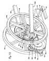
- FIGURE 16A still further preferred embodiment of the present invention is illustrated in FIGURE 16. Multi-pivoting connections between the foot links 30a' and 30b' to flywheels 24a and 24b are provided.
- a rail pivot block 230is pivotally pinned to each flywheel 24a and 24b at apertures 104 by a threaded fastener 232 and mating nut 234.
- the rail pivot blocks 230move in a plane approximately parallel to the plane of the corresponding flywheel.
- Foot links 30a' and 30b'are hollow at the rear ends for receiving the rail pivot blocks 230.
- a block mounting pin 231extends through opposing holes on the top and bottom of the rear end of foot links 30a' and 30b' and snugly through a hole in the pivot block for attaching the pivot block 230 to the rear end of the foot links.
- Slots 236extend longitudinally from the rear ends of foot links 30a and 30b allow access to the fasteners 232 and 234.
- the rail pivot blocks 230are generally rectangular in shape and sized to fit between the upper and lower flange walls of the hollow foot links. However, the internal width of the flange portions of the foot links is wider than the thickness of the rail pivot blocks 230 to allow angular displacement of the foot links relative to pivot block about mounting pin 231, which acts as the pivot point.
- This constructionprovides a foot link connection between the flywheels 24a and 24b and guides 36 that compensate for possible inconsistencies in the alignment of the flywheels 24a and 24b as well as the guide 36, especially in the direction transverse to the length of the foot links 30a and 30b. It can be appreciated to one of ordinary skill that varying the thickness of rail pivot blocks 230 and the position of the block mounting pins 231 allow a designer to fine tune the construction depending on expected tolerances that may occur in the alignment of the other components of the present invention.
Landscapes
- Health & Medical Sciences (AREA)
- General Health & Medical Sciences (AREA)
- Physical Education & Sports Medicine (AREA)
- Cardiology (AREA)
- Vascular Medicine (AREA)
- Rehabilitation Tools (AREA)
Description
- The present invention relates to exercise equipment, and more specifically to astationary exercise device for simulating a range of stepping motions, including skiing,walking, jogging, running and climbing.
- The benefits of regular aerobic exercise has been well established andaccepted. Because of inclement weather, time constraints and for other reasons, it isnot possible to always walk, jog or run outdoors or swim in a pool. As such, varioustypes of exercise equipment have been developed for aerobic exercise. For example,cross country skiing exercise devices simulate the gliding motion of cross countryskiing. Such machines provide a good range of motion for the muscles of the legs.Treadmills are also utilized by many people for walking, jogging or even running.One drawback of most treadmills is that during jogging or running, significant jarringof the hip, knee, ankle and other joints of the body may occur. Another type ofexercise device simulates stair climbing. Such devices can be composed of foot leversthat are pivotally mounted to a frame at their forward ends and have foot receivingpads at their rearward ends. The user pushes his/her feet down against the foot leversto simulate stair climbing. Resistance to the downward movement of the foot leversis provided by springs, fluid shock absorbers and/or other elements. Furthermore, document US-A-5 242 343discloses an exercise device having a pair of foot links eachguided such that, in use, a user's foot describes a reciprocal oval path.
- The aforementioned devices exercise different muscles of the user's legs andother parts of the body. Thus, to exercise all of these muscles, three separate exerciseapparatus are needed. This not only may be cost prohibitive, but also many people donot have enough physical space for all of this equipment. Further, if only one of theforegoing exercise apparatus is purchased by a user, the user may tire of alwaysutilizing the singular equipment and may desire to use other types of equipment.
- Through the present invention, a singular piece of equipment may be utilizedto simulate different exercise apparatus, including cross country skiing, walking,jogging, running and climbing. Further, jogging and running are simulated withoutimparting shock to the user's body joints in the manner of exercise treadmills.
- These and other advantages of the present invention will be readily apparentfrom the drawings, discussion and description which follow.
- The exercise device of the present invention utilizes a frame configured to besupported on a floor. The frame defines a rearward pivot axis about which first andsecond foot links are coupled to travel along an arcuate path relative to the pivot axis.The foot links, adapted to support the user's feet, have forward ends that are engagedwith a guide mounted on the frame to enable the forward ends of the foot links totravel back and forth along a defined path. The angular elevation of the guide and/orthe elevation of the guide relative to the frame may be selectively changed to alter thepath traveled by the foot supporting portion of the first and second links thereby tosimulate various types of stepping motion.
- In a more specific aspect of the present invention, the guide includes rails forreceiving and guiding the forward ends of the foot links. The rails may be raised andlowered relative to the frame. For example, the guides may be pivotally mounted onthe frame, and the angle of inclination of the guides may be selectively altered.
- In a yet more specific aspect of the present invention, the guides may be in theform of tracks that engage with the forward ends of the foot links. The elevationand/or angular orientation of the tracks relative to the frame may be selectivelychanged thereby to alter the types of stepping motion experienced by the user.
- In another aspect of the present invention, the guide for the forward ends ofthe foot links may include one or more pivot or rocker arms pivotally supported bythe frame, with the lower ends of the rocker arms pivotally connected to the forwardends of the foot links. The lengths of the rocker arms may be lengthened or shortenedthereby to raise and lower the connection point between the rocker arms and the forward ends of the foot links, thereby to change the type of stepping motionexperienced by the user.
- In a further aspect of the present invention, flywheels are mounted on arearward portion of the frame to rotate about the frame pivot axis. The rearwardends of the foot links are pivotally pinned to the flywheels at a selective location fromthe frame pivot axis. The flywheel serves not only as the coupling means between therearward ends of the foot links and the frame pivot axis, but also as a momentumstoring device to simulate the momentum of the body during various steppingmotions.
- According to a further aspect of the present invention, resistance may beapplied to the rotation of the flywheels, to make the stepping motion harder or easierto achieve. This resistance may be coordinated with the workout level desired by theuser, for instance, a desired heart rate range for optimum caloric expenditure. A heartrate monitor or other sensor may be utilized to sense the desired physical parameter tobe optimized during exercise.
- In a still further aspect of the present invention, the rearward end of the footlinks are connected to the pivot axis by a connection system that allows relativepivoting motion between the pivot axis and foot links about two axes, bothorthogonal (transverse) to the length of the foot links. As such, the forward ends ofthe foot links are free to move or shift relative to the rearward ends of the foot links inthe sideways direction, i.e., traverse to the length of the foot links.
- The foregoing aspects and many of the advantages of the present inventionwill be more readily appreciated as the same becomes better understood by referenceto the following detailed description, when taken in conjunction with theaccompanying drawings, wherein:
- FIGURE 1 is a perspective view of an exercise apparatus of the presentinvention looking from the rear toward the front of the apparatus;
- FIGURE 2 is a top view of the apparatus of FIGURE 1;
- FIGURE 3 is a bottom view of the apparatus of FIGURE 1;
- FIGURE 4 is a front view of the apparatus of FIGURE 1;
- FIGURE 5 is a rear view of the apparatus of FIGURE 1;
- FIGURE 6 is side elevational view of the apparatus of FIGURE 1;
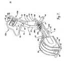
- FIGURE 7 is a perspective view of the apparatus of FIGURE 1, wherein ahood has been installed over the rear portion of the apparatus, this perspective viewlooks from the rear of the apparatus towards the front;
- FIGURE 8 is a view similar to FIGURE 7, but looking from the front of theapparatus towards the rear;
- FIGURE 9 is a view similar to FIGURE 8, but with the front and rear hoodsremoved;
- FIGURE 10 is an enlarged, fragmentary, perspective view of the forwardportion of the apparatus shown in FIGURE 9;
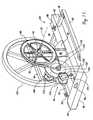
- FIGURE 11 is an enlarged, fragmentary, rear perspective view of theapparatus shown in FIGURE 9, with one of the flywheels removed;
- FIGURE 12 is a view similar to FIGURE 11, but from the opposite side of theapparatus and with the near flywheel removed;
- FIGURE 13 is a side elevational view of the apparatus of the present inventionshown in schematic illustrating the paths of the user's foot at different angles ofinclination of the guide for the foot links;
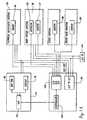
- FIGURE 14 is a schematic drawing of the system utilized in the presentinvention for altering the workout level while utilizing the present apparatus; and,
- FIGURE 15 is a side elevational view of a further preferred embodiment of thepresent invention; and
- FIGURE 16 is an enlarged, partial perspective view of a further preferredembodiment of the present invention.
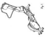
- Referring initially to FIGURES 1-9, the
apparatus 18 of the present inventionincludes afloor engaging frame 20 incorporating aforward post 22 extending initiallyupwardly and then diagonally forwardly. A pair of flywheels 24a and 24b are locatedat the rear of theframe 20 for rotation about a horizontal,transverse axis 26. Theflywheels 24a and 24b may be covered by arear hood 28. The rearward ends of footlinks 28a and 28b are pivotally attached to corresponding flywheels 24a and 24b totravel about a circular path aroundaxis 26 as the flywheels rotate.Rollers foot links tubular tracks 34a and 34b of aguide 36. The forward ends ofthefoot links tracks 34a and 34b as therearward ends of the foot links rotate aboutaxis 26 causing the foot pedals orpads 27carried by the foot links to travel along various elliptical paths, as described more fullybelow. - A
lift mechanism 38, mounted on thepost 22, is operable to selectively changethe inclination of theguide 36 thereby to alter the stepping motion of the user of theapparatus of the present invention. At a low angle of inclination, the apparatus provides a cross country skiing motion and as the angle of inclination progressivelyrises, the motion changes from walking to running to climbing. Aforward hood 39substantially encases the lift mechanisms. - In addition, as most clearly shown in FIGURES 11 and 12, the presentinvention employs a
braking system 40 for imparting a desired level of resistance tothe rotation of flywheels 24a and 24b, and thus, the level of effort required of the userofapparatus 18. The following description describes the foregoing and other aspectsof the present invention in greater detail. Frame 20 is illustrated as including a longitudinalcentral member 42terminating at front and rear relatively shortertransverse members frame 20 is composed of rectangular tubular members, whichare relatively light in weight but provide substantial strength. End caps 48 areengaged within the open ends of thetransverse members - The
post structure 22 includes a lower, substantiallyvertical section 52 and anupper section 54 that extends diagonally upwardly and forwardly from the lowersection. Ideally, but not essentially, the post lower andupper sections end cap 48 also engages withinthe upper end of the postupper section 54 to close off the opening therein. - A continuous, closed
form handle bar 56 is mounted on the upper portion ofpostupper section 54 for grasping by an individual while utilizing thepresentapparatus 18. The handle bar includes an uppertransverse section 58 which issecurely attached to the upper end of the postupper section 54 by aclamp 60engaging around the handle bar upper section and securable to the post upper sectionby a pair offasteners 62. The handle bar also includes side sections 62a and 62b eachcomposed of an upper diagonally disposed section, an intermediate, substantiallyvertical section and lower diagonally disposed sections 68a and 68b extendingdownwardly and flaring outwardly from the intermediate side sections. Thehandlebar 56 also includes a transverselower section 70 having a central portion clamped topostupper section 54 by aclamp 60, which is held in place by a pair offasteners 62.Although not shown, thehandle bar 56 may be in part or in whole covered by agripping material or surface, such as tape, foamed synthetic rubber, etc. - A
display panel 74 is mounted on the post barupper section 54 at a locationbetween the upper and lowertransverse sections handle bar 56. Thedisplay panel includes acentral display screen 76 and several smaller screens 78 as well as a keypad composed of a number of depressible "buttons" 80, as discussed ingreater detail below. - The flywheels 24a and 24b are mounted on the outboard, opposite ends of a
drive shaft 84 rotatably extending transversely through the upper end of arear post 86extending upwardly from a rear portion of the framecentral member 42. A bearingassembly 88 is employed to anti-frictionally mount thedrive shaft 84 on therearpost 86. In a preferred embodiment of the present invention, the flywheels 24aand 24b are keyed or otherwise attached to thedrive shaft 84 so that the flywheelsrotate in unison with the drive shaft. It will be appreciated that the center of thedriveshaft 84 corresponds with the location oftransverse axis 26. Abelt drive sheave 90 isalso mounted ondrive shaft 84 between flywheel 24a and the adjacent side ofrearpost 86. - The
rear post 86 may be fixedly attached to framelongitudinal member 42 byany expedient manner, such as by welding or bolting. In accordance with a preferredembodiment of the present invention, acorner type brace 92 is employed at thejuncture of the forward lower section ofrear post 86 with the upper surface oflongitudinal member 42 to provide reinforcement therebetween. Of course, othertypes of bracing or reinforcement may be utilized. - The flywheels 24a and 24b are illustrated as incorporating
spokes 94 thatradiate outwardly from acentral hub 95 to intersect acircumferential rim 96. Theflywheels 24a and 24b may be of other constructions, for instance, in the form of asubstantially solid disk, without departing from the spirit or scope of the presentinvention. - The
rear hood 28 encloses the flywheels 24a and 24b, thebrake system 40 andthe rear portions of thefoot links hood 28 rests on frame reartransverse member 46 as well as on a pair of auxiliarylongitudinal members 97extending forwardly from thetransverse member 46 to intersect the outward ends ofauxiliary intermediatetransverse members 98. The upper surfaces of thehoodsupport members frame member attachment brackets 99 are mounted on the uppersurfaces of theauxiliary support members frame members brackets 99 to receive fasteners used toattach thehood 28 thereto. As most clearly illustrated in FIGURES 11 and 12,ideally in cross section the heights ofhood support members frame members - The foot links 30a and 30b as illustrated are composed of elongate tubularmembers but can be of other types of construction, for example, solid rods. The rearends of the
foot links fasteners 100 that extend throughcollars 102 formed at therear ends of the foot links to engage withinapertures 104 formed in perimeterportions of the flywheels. As most clearly shown in FIGURE 12, theaperture 104 islocated at the juncture between flywheel spoke 94 and theouter rim 96. This portionof the flywheel has been enlarged to form aboss 106. The foot links 30a and 30bextend outwardly of the front side ofhood 28 throughvertical openings 108 formedin the front wall of the hood. - As also shown in FIGURE 12, a
second boss 110 is formed on thediametrically opposite spoke to the spoke on whichboss 106 is located, but at alocation closer toaxis 26 than thelocation boss 106. Thecollars 102 at the rear endsof the foot links may be attached to the flywheels atbosses 110 instead ofbosses 106,thereby reducing the diameter of the circumferential paths traveled by the rear ends ofthe foot links during rotation of the flywheel, and thus, correspondingly shortening thelength of the elliptical path circumscribed by thefoot pedals 27. It will be appreciatedthat attaching thecollars 102 tobosses 110 results in a shorter stroke of the footlinks, and thus, a shorter stride taken by the exerciser in comparison to the striderequired when the collars are attached to the flywheels atbosses 106. Concave rollers foot links cross shafts 114. The concave curvature of the rollerscoincide with the diameter of thetracks 34a and 34b of theguide 36. As such, therollers guide 36 during use of the present apparatus.Foot receiving pedals 27 aremounted on the upper surfaces of the foot links 30 to receive and retain the user'sfoot. Thepedals 27 are illustrated as formed with a plurality of transverse ridges thatnot only enhance the structural integrity of the foot pads, but also serve an anti-skidfunction between the bottom of the user's shoe or foot and the foot pedals. Althoughnot shown, the foot pedals may be designed to be positionable along the length of thefoot links to accommodate user's of different heights and in particular different leglengths or in seams.- The
guide 36 is illustrated as generally U-shaped with its rearward, free endspivotally pinned to an intermediate location along the length of framecentralmember 42. The free ends of theguide 36 may be pivotally attached to thecentralframe member 42 by any convenient method, including by being journaled over the outer ends of across tube 118. The guide is composed of parallel,tubular tracks 34aand 34b disposed in alignment with thefoot links tracks 34a and 34b are joined together by anarcuate portion 119 that crosses thepost 22 forwardly thereof. - The forward portion of the
guide 36 is supported bylift mechanism 38, whichis most dearly shown in FIGURES 9 and 10. Thelift mechanism 38 includes acrossbar 120 supported by the lower end of a generally U-shaped, verticallymovablecarriage 122.Roller tube sections 124 are engaged over the outer ends of thecrossbar 120 to directly underlie and bear against the bottoms oftracks 34a and 34b.Thecarriage 122 is restrained to travel vertically along the height of acentral guidebar 126 which is securely fastened to the forward face of the postlower section 54 byany appropriate method, such as byfasteners 128. In cross section, theguide bar 126is generally T-shaped, having a central web portion that bears against the postlowersection 52 and transversely extending flange portions that are spaced forwardly of thepost lower section. A pair of generally Z-shapedretention brackets 130 retain thecarriage 122 in engagement with theguide bar 126. The retention brackets eachinclude a first transverse flange section mounted to the back flange surface of thecarriage, an intermediate web section extending along the outer side edges of theguide bar flanges and a second transverse flange section disposed within the gapformed by the front surface of the postlower section 52 and the opposite surface ofthe guide bar flange. It will be appreciated that by this construction thecarriage 122is allowed to vertically travel relative to theguide bar 126 but is retained inengagement with the guide bar. - The
carriage 122 is raised and lowered by an electricallypowered liftactuator 136. Thelift actuator 136 includes anupper screw section 138 is rotatablypowered by anelectric motor 140 operably connected to the upper end of the screwsection. The top of the screw section is rotatably engaged with a retainingsocketassembly 142 which is pinned to aU-shaped bracket 144 secured to the forward faceofpost 22 near the juncture of the postlower section 52 andupper section 54. Across pin 146 extends through aligned openings formed in the flanges of thebracket 144 and aligned diametrically opposed apertures formed in thesocket 142.Thesocket 142 allows thescrew 138 to rotate relative to the socket while remainingin vertical engagement with the collar. - The lower portion of the
screw section 138 threadably engages within a lowertubular casing 147 having its bottom end portion fixedly attached tocrossbar 120. Itwill be appreciated thatmotor 140 may be operable to rotate thescrew section 138 in one direction to lower thecarriage 122 or in the opposite direction to raise thecarriage, as desired. As the carriage is lowered or raised, the angle of inclination oftheguide 36 is changed which in turn changes the stepping motion experienced by theuser ofapparatus 18. The engagement of thescrew section 138 into thecasing 120,and thus the angle of inclination of theguide 36, is readily discernible by standardtechniques, for instance by using arotating potentiometer 147, FIGURE 14. - The
forward hood 39 substantially encases thelift mechanism 38. Thehood 39 extends forwardly from the side walls of the post lower anduppersections carriage 122,guide bar 126,lift actuator 136 andother components of the lift mechanism. Only the free ends of thecross bar 120 andassociatedroller tube sections 124 protrude outwardly fromvertical slots 148 formedin the side walls of thehood 39. A plurality offasteners 149 are provided todetachably attach thehood 39 to the side walls of thepost 22. - The present invention includes a system for selectively applying the braking orretarding force on the rotation of the flywheels through a eddy
current brakesystem 40. Thebrake system 40 includes alarger drive sheave 90, noted above, thatdrives a smaller drivensheave 150 through a V-belt 152. The drivensheave 150 ismounted on the free end of arotatable stub shaft 154 that extends outwardly from apivot arm 156 pivotally mounted to the rear side ofrear post 86 by aU-shapedbracket 158 and apivot pin 160 extending through aligned openings formed in thebracket as well as aligned openings formed in the side walls of thepivot arm 156. Anextension spring 161 extends between the bottom ofarm 156 at the free end thereofand the top offrame member 42 to maintain sufficient tension onbelt 152 to avoidslippage between the belt and thesheaves sheaves shaft 154 rotates about sixto ten times faster than thedrive shaft 84. - A solid
metallic disk 162 is mounted onstub shaft 154 inboard of drivensheave 150 to also rotate with the driven sheave. Ideally, anannular face plate 164 ofhighly electrically conductive material, e.g., copper, is mounted on the face of thesolid disk 162 adjacent the drivenpulley 150. A pair ofmagnet assemblies 168 aremounted closely adjacent the face of thesolid disk 162 opposite theannular plate 164.Theassemblies 168 each include a central core in the form of abar magnet 170surrounded by acoil assembly 172. Theassemblies 168 are mounted on akeeperbar 174 byfasteners 176 extending through aligned holes formed in the keeper barand the magnet cores. As illustrated in FIGURES 11 and 12, themagnet assemblies 168 are positioned along the outer perimeter portion of thedisk 162 inalignment with theannular plate 164. The location of the magnet assemblies may beadjusted relative to the adjacent face of thedisk 162 so as to be positioned as closelyas possible to the disk without actually touching or interfering with the rotation of thedisk. This positioning of themagnet assemblies 168 is accomplished by adjusting theposition of thekeeper bar 174 relative to asupport plate 178 mounted on therearward, free end ofpivot arm 156. A pair of horizontal slots, not shown, areformed in thesupport plate 178 through which extend threadedfasteners 179 thatthen engage within tapped holes formed in the forward edge of thekeeper bar 174. - As noted above, the significant difference in size between the diameters of
drive sheave 90 and drivensheave 150 results in a substantial step up in rotationalspeed of thedisk 62 relative to the rotational speed of the flywheels 24a and 24b. Therotational speed of thedisk 62 is thereby sufficient to produce relatively high levels ofbraking torque through the eddycurrent brake assembly 40. - As discussed more fully below, it is desirable to monitor the speed of thewheels 24a and 24b so as to measure the distance traveled by the user of thepresent apparatus and also to control the level of workout experienced by the user.Any standard method of measuring the speed of the flywheels may be utilized. Forinstance, an optical or magnetic strobe wheel may be mounted on
disk 162, drivesheave 90 or other rotating member of the present apparatus. The rotational speed ofthe strobe wheel may be monitored by an optical or magnetic sensor 180(FIGURE 14) to generate an electrical signal related to such rotational speed. - To use the present invention, the user stands on the
foot pads 27 whilegripping thehandle bar 56 for stability. The user imparts a downward stepping actionon one foot pads thereby causing the flywheels 24a and 24b to rotate aboutaxis 26.As a result, the rear ends of the foot links rotate about theaxis 26 and simultaneouslythe forward ends of the foot links ride up and down thetracks 34a and 34b. Theforward end of the foot link moves downwardly along its track as the point ofattachment of the foot link to the flywheel moves from a location substantially closestto the post 22 (maximum extended position of the foot link) to a location substantiallyfurthest from the post, i.e., the maximum retracted position of the foot link. From thispoint of the maximum retracted position of the foot link, further rotation of theflywheel causes the foot link to travel back upwardly and forwardly along thetrack 34a back to the maximum extended position of the foot link. These twopositions are shown in FIGURE 13. FIGURE 13 also illustrates the correspondingpath of travel of the center of thefoot pads 27, and thus, the path of travel of the user's feet. As shown in FIGURE 13, this path of travel is basically in the shape of aforwardly and upwardly tilted ellipse. - FIGURE 13 shows the path of travel of the
foot pad 27 at three differentangular orientations ofguide 36 corresponding to different elevations of theliftmechanism 38. In the smallest angular orientation shown in FIGURE 13(approximately 10° above the horizontal), the corresponding footpad travel path 181is illustrated. This generally corresponds to a gliding or cross-country skiing motion.Theguide 36 is shown at a second orientation at a steeper angle (approximately 20°)from the horizontal, with the corresponding path of travel, of the foot pedal 116depicted byelliptical path 182. This path of travel generally corresponds to a walkingmotion. FIGURE 13 also illustrates a third even steeper angular orientation of theguide 36, approximately 30° from the horizontal. The corresponding elliptical path oftravel of thefoot pad 27 is illustrated by 183 in FIGURE 13. This path of travelcorresponds to a climbing motion. It will be appreciated that by adjusting the angle oftheguide 36, different types of motion are attainable through the present invention.Thus, the present invention may be utilized to emulate different types of physicalactivity, from skiing to walking to running to climbing. Heretofore to achieve thesedifferent motions, different exercise equipment would have been needed. - Applicants note that in each of the foregoing different paths of travel of thefoot pad, and thus also the user's feet, a common relationship occurs. When the rearend of a foot link travels forwardly from a rearmost position, for instance, as shown inFIGURE 13, the heel portion of the user's foot initially rises at a faster rate than thetoe portion of the user's foot. Correspondingly, when the rearward end of the footlink travels rearwardly from a foremost position, the heel portion of the user's footinitially lowers at a faster rate than the toe portion. This same relationship is truewhen the forward ends of the foot links travel from a position at the lower end of the
guide 36 to a position at the upper end of theguide 36. In other words, when theforward end of a foot link travels from a lower, rearmost point alongguide 36forwardly and upwardly along the guide, the heel portion of the user's foot initiallyrises at a faster rate than the toe portion. Correspondingly, when the forward end ofthe foot link travels downwardly and rearwardly from an upper, forwardmost locationalong theguide 36, the heel portion of the user's foot initially lowers at a faster ratethan the toe portion. This generally corresponds with the relative motion of the user'sheel and toe during cross country skiing, walking, running and climbing or otherstepping motions. - Applicants'
system 184 for controlling and coordinating the angle ofinclination of theguide 36 and the resistance applied to the rotation of theflywheels 24a and 24b to achieve a desired workout level is illustrated schematically inFIGURE 14. As shown in FIGURE 14, a physical workout parameter, e.g., user'sheart rate, is monitored by asensor 186. An electrical signal, typically analog innature, related to the user's heart rate is generated. Various types of heart ratemonitors are available, including chest worn monitors, ear lobe monitors and fingermonitors. The output from themonitor 186 is routed through an analog todigitalinterface 188, throughcontroller 190 and to a central processing unit (CPU) 192,ideally located withindisplay panel 74. In addition to, or in lieu of, the user's heartrate, other physical parameters of the exerciser may be utilized, including respiratoryrate, age, weight, sex, etc. - Continuing to refer to FIGURE 14, the
exercise control system 184 of thepresent invention includes an alternatingcurrent power inlet 194 connectable to astandard amperage AC 110 volt power supply. Thepower inlet 194 is routed to atransformer 196 and then on to thebrake system 40 and thedisplay panel 74. Theliftmechanism 38 utilizes AC power, and thus, is not connected to thetransformer 196. - As previously discussed, the
lift mechanism 38 incorporates asensingsystem 147 to sense the extension and retraction of the lift mechanism, and thus, theangle of inclination of theguide 36. This information is routed through the analog todigital interface 188, throughcontroller 190 and to theCPU 192. The rotationalspeed of the flywheels 24a and 24b is also monitored by asensor 180, as discussedabove, with this information is transmitted to the CPU through the analog todigitalinterface 188 andcontroller 190. Thus, during use of theapparatus 18 of the presentinvention, the CPU is apprised of the heart rate or other physical parameter of theexerciser being sensed bysensor 186, the angle of inclination of theguide 36 and thespeed of the flywheels 24a and 24b. This information, or related information, may bedisplayed to the exerciser throughdisplay 76. - Further, through the present invention, a desired workout level may bemaintained through the
control system 184. For instance, certain parameters may beinputted through thekeypad 80 by the exerciser, such as age, height, sex, to achieve adesired heart rate range during exercise. Alternatively, the desired heart rate rangemay be directly entered by the exerciser. Other parameters may or may not beinputted by the exerciser, such as the desired speed of the flywheels corresponding tocycles per minute of the foot links and/or inclination of theguide 36. With this information, the control system of the present invention will adjust thebrakingsystem 40 and/orlift mechanism 38 to achieve the desired workout level. - It is to be understood that various courses or workout regimes may bepreprogrammed into the
CPU 192 or designed by the user to reflect variousparameters, including a desired cardiovascular range, type of stepping action, etc.Thecontrol system 184 thereupon will control thebrake system 40 as well as theliftmechanism 38 to correspond to the desired workout regime. - A further preferred embodiment of the present invention is illustrated inFIGURE 15. The apparatus 18' shown in FIGURE 15 is constructed similarly to
apparatus 18 shown in the prior figures. Accordingly, those components ofapparatus 18' that are the same as, or similar to, those components ofapparatus 18bear the same part number, but with the addition of the prime ("'") designation. - Apparatus 18' includes a single flywheel 24' rotatably mounted at the rear offrame 20'. A pair of crank arms 200a and 200b extend transversely in diametricallyopposite directions from the ends of a
drive shaft 84' to pivotally connect to the rearends offoot links 30a' and 30b'. The crank arms 200a and 200b are fixedly attachedto thedrive shaft 84'. It will be appreciated that the crank arms 200a and 200bsupport the rear ends of thefoot links 30a' and 30b' during fore and aft motionthereof. In this regard, the lengths of the crank arms can be altered to change the"stroke" of the foot links to accommodate uses of different leg/inseam lengths. - The forward ends of the
foot links 30a' and 30b' are pivotally pinned to thelower ends of rocker or swing arms 201a and 201 b at pivot joints 202. The swingarms are preferably tubular in construction and dog-leg in shape, having their upperends pinned to post 22' ataxis 204 near the intersection of lower section 52' andupper section 54' of the post. Each of the swing arms includes a tubularuppersection 206 and a tubularlower section 208. The upper end portion of thelowersection 208 slidably engages within the lower end portion of a correspondinguppersection 206, thereby to selectively alter the length of the swing arms. The swing armupper and lower sections may be maintained in engagement with each other by anyconvenient means, such as by across pin 210 extending through diametrically alignedopenings formed in the swing arm upper section and one of the sets of diametricallyaligned openings formed in the lower sections. - Although not illustrated, an extension spring or other device may be locatedwith the interior of the swing arm upper and lower sections to bias the upper andlower sections into engagement with each other. Alternatively, the engagement of theswing arm upper and lower sections may be "automatically" controlled by incorporating a linear actuator or other powered device into the construction of theswing arms.
- The swing arms 201a and 201b support the forward ends of the
foot links 30a'and 30b' to travel along anarcuate path 212 defined by thepivot axis 204 of the upperends of the swing arms aboutpost 22' and the radial length betweensuch axis 204 andthepivot point 202 defining the connection point of the forward end of the foot linkand the lower end of its corresponding swing arm. It will be appreciated that thepath 212 may be altered as the relative engagement between the swing armuppersection 206 andlower section 208 is changed. This results in a change in the steppingmotion experienced by the user, which stepping motion may be altered in a mannersimilar to that achieved by varying the angle of inclination ofguide 36, discussedabove. As such, the apparatus 18' is capable or providing the same advantages asprovided by theapparatus 18, noted above. - A
band brake system 220 is provided to selectively impart rotational resistanceon the flywheel 24'. The band brake system includes abrake band 222 that extendsaround the outer rim of the flywheel 24' and also about a smalldiameter takeuproller 224 that is rotatably attached to the outer/free end of alinear actuator 226. Theopposite end of the linear actuator is pivotally pinned to a mountingbracket 226attached to frame 42'. It will be appreciated that the linear actuator may bemechanically, electrically or otherwise selectively controlled by the user to impart adesired frictional load on the flywheel 24'. Also, other known methods may be usedto impart a desired level of rotational resistance on the flywheel 24'. For instance, acaliper brake (not shown) can be employed to engage against the outer rim portion ofthe flywheel itself or on a disk (not shown) that rotates with the flywheel. - A still further preferred embodiment of the present invention is illustrated inFIGURE 16. Multi-pivoting connections between the
foot links 30a' and 30b' toflywheels 24a and 24b are provided. Arail pivot block 230 is pivotally pinned to eachflywheel 24a and 24b atapertures 104 by a threadedfastener 232 andmating nut 234.The rail pivot blocks 230 move in a plane approximately parallel to the plane of thecorresponding flywheel.Foot links 30a' and 30b' are hollow at the rear ends forreceiving the rail pivot blocks 230. Ablock mounting pin 231 extends throughopposing holes on the top and bottom of the rear end offoot links 30a' and 30b' andsnugly through a hole in the pivot block for attaching thepivot block 230 to the rearend of the foot links. Slots 236 extend longitudinally from the rear ends offootlinks fasteners - Ideally, the rail pivot blocks 230 are generally rectangular in shape and sizedto fit between the upper and lower flange walls of the hollow foot links. However,the internal width of the flange portions of the foot links is wider than the thickness ofthe rail pivot blocks 230 to allow angular displacement of the foot links relative topivot block about mounting
pin 231, which acts as the pivot point. This constructionprovides a foot link connection between the flywheels 24a and 24b and guides 36 thatcompensate for possible inconsistencies in the alignment of the flywheels 24a and 24bas well as theguide 36, especially in the direction transverse to the length of thefootlinks block mounting pins 231allow a designer to fine tune the construction depending on expected tolerances thatmay occur in the alignment of the other components of the present invention. - While preferred embodiments of the present invention have been illustratedand described, it would be appreciated that various changes may be made theretowithout departing from the spirit and scope of the present invention.
Claims (17)
- An exercise device to simulate various types of stepping motions, comprising;a frame (20) having a forward end portion and a rearward end portion and a pivot axis(26) defined near the rearward end portion thereon;a first (30a) and second (30b) foot link, each foot link including a rear end portion, afront end portion, and a foot supporting portion (27) therebetween;a coupling system (100, 102, 104, 106, 110) associated with the rear end portion ofeach foot link (30a, 30b) for pivotally connecting the rear end of each foot link (30a, 30b) tothe pivot axis (26) so that the first end travels in an arcuate path relative to the pivot axis (26)wherein the coupling system (100, 102, 104, 106, 110) connecting the rear end portions ofthe foot links at selective distances from the frame pivot axis (26) to alter the arcuate paths oftravel of the rear end portions of the foot links travel relative to the frame pivot axis;a guide (36) to engage and direct the forward end portions of the foot links (30a, 30b)along preselected reciprocating paths of travel as the rear end portions of the respective footlinks (30a, 30b) travel along arcuate paths of travel so that when the exercise device is in usewith the user facing the forward end portion of the frame and when the rear end portions ofone of the foot links is traveling forwardly from a rearmost position towards a foremostposition, the heel portion of the user's foot initially rises at a faster rate than a toe portionthereof, and when the rear end portions of the foot link is traveling rearwardly from aforemost position towards a rearmost position, the heel portion of the user's foot initiallylowers at a faster rate than the toe portion.
- The exercise device according to Claim 1, wherein the coupling system (100,102, 104, 106, 110) includes first (24a) and second (24b) wheels rotatably mounted on the frame (20) about the frame pivot axis (26) and the coupling system pivotally connecting therear end portions of the first (28a) and second (28b) foot links to the first and second wheels.
- The exercise device according to Claim 2, wherein the rear end portions of thefirst (28a) and second (28b) foot links are pivotally connectable to a flywheel assembly (24a,24b) at selective locations (106, 110) relative to the frame pivot axis (26).
- The exercise device according to Claim 1, wherein the coupling system (100,102, 104, 106, 110) including pivot means (230, 231, 232, 234) for pivotally connecting therear end portions of the first (28a) and second (28b) foot links to the pivot axis (26) whileallowing lateral angular displacement of the foot links at the connection between the rear endportions of the foot links and the pivot axis (26).
- The exercise device according to Claim 4, wherein the coupling system (100,102, 104, 106, 110) includes first (200a) and second (200b) crank arms, with one end of eachcrank arm pivotable about the pivot axis (26') and the other end of each crank arm pivotallypinned to the rear end portion of a corresponding first (201a) and second (201b) foot link.
- The exercise device according to Claim 5, wherein the pivot means (230, 231,232, 234) are interposed between the ends of the crank arms (200a, 200b) opposite the pivotaxis (26') and the rear end portions of the first (201a) and second (201b) foot links, the pivotmeans pivotally connected about a first axis (232) with the crank arms and pivotallyconnected about a second axis (231) with the rear end portions of the first and second footlinks, with the first and second axes of the pivot means being substantially orthogonal to eachother.
- The exercise device of Claim 4, wherein the pivot means (230, 231, 232, 234)has two orthogonal axes (232, 231) of rotation.
- The exercise device of Claim 1, wherein the guide (36) is disposed at aninclined relationship with the floor, and a control system (38) is operable to alter theinclination of the guide relative to the floor.
- The exercise device according to Claim 8, wherein the guide (36) extendslongitudinally relative to the frame (20) and in general alignment with the first (28a) andsecond (28b) foot links, and wherein the guide includes means (118) for pivotally attachingthe guide to the frame about a pivot axis, and the control system (38) includes means forvarying the orientation of the guide relative to the frame about the guide pivot axis.
- The exercise device according to Claim 1, wherein the control system (38)includes means (136) for raising and lowering the guide relative to the frame.
- The exercise device according to Claim 1, wherein the guide (36) comprisesfirst (34a) and second (34b) tracks, and the control system (38) operably engaging the tracksto alter the orientation of the tracks relative to the frame (20).
- The exercise device according to Claim 11, wherein the control system (38)operably engaging the tracks (34a, 34b) to vary the angular orientation of the tracks relativeto the frame (20).
- The exercise device according to Claim 1, wherein the guide (200a, 200b) ispivotally supported by the frame (421), and the control system (208, 210) operably engagesthe guide to raise and lower the guide relative to the frame.
- The exercise device according to Claim 13, wherein the guide (200a, 200b)includes at least one rocker arm (200a, 200b) pivotally supported by the frame (421) andpivotally connected to a forward end portion of the first (201a) and second (201b) links.
- The exercise device according to Claim 14, wherein the control system (208,210) operably engages the rocker arm (200a, 200b) to raise and lower the rocker arm relativeto the frame.
- The exercise device according to Claim 15, wherein the control systemincludes means (208, 201) for altering the length of the rocker arm thereby to adjust theelevation of the guide (200a, 200b).
- The exercise device according to Claim 1, further comprising a housing (28)for enclosing the coupling system (100, 102, 104, 106, 110) and rearward end portions of thefirst (30a) and second (30b) first links, thereby to also serve as a rear abutment to the feet ofthe user.
Applications Claiming Priority (7)
| Application Number | Priority Date | Filing Date | Title |
|---|---|---|---|
| US56849995A | 1995-12-07 | 1995-12-07 | |
| US670515 | 1996-06-27 | ||
| US08/670,515US5685804A (en) | 1995-12-07 | 1996-06-27 | Stationary exercise device |
| EP97932280AEP0858358B1 (en) | 1996-06-27 | 1997-06-26 | Stationary exercise device |
| US08/967,801US6146313A (en) | 1995-12-07 | 1997-11-10 | Cross training exercise device |
| US09/382,555US6749540B1 (en) | 1995-12-07 | 1999-08-25 | Cross training exercise device |
| US09/382,556US6482130B1 (en) | 1995-12-07 | 1999-08-25 | Cross training exercise device |
Related Parent Applications (1)
| Application Number | Title | Priority Date | Filing Date |
|---|---|---|---|
| EP97932280ADivisionEP0858358B1 (en) | 1995-12-07 | 1997-06-26 | Stationary exercise device |
Publications (3)
| Publication Number | Publication Date |
|---|---|
| EP1004332A2 EP1004332A2 (en) | 2000-05-31 |
| EP1004332A3 EP1004332A3 (en) | 2000-10-04 |
| EP1004332B1true EP1004332B1 (en) | 2005-05-04 |
Family
ID=46305037
Family Applications (2)
| Application Number | Title | Priority Date | Filing Date |
|---|---|---|---|
| EP00104023AExpired - LifetimeEP1004332B1 (en) | 1995-12-07 | 1997-06-26 | Stationary exercise device |
| EP98309155AExpired - LifetimeEP0914842B1 (en) | 1995-12-07 | 1998-11-09 | Cross training exercise device |
Family Applications After (1)
| Application Number | Title | Priority Date | Filing Date |
|---|---|---|---|
| EP98309155AExpired - LifetimeEP0914842B1 (en) | 1995-12-07 | 1998-11-09 | Cross training exercise device |
Country Status (3)
| Country | Link |
|---|---|
| US (3) | US5685804A (en) |
| EP (2) | EP1004332B1 (en) |
| WO (1) | WO1997049460A1 (en) |
Cited By (1)
| Publication number | Priority date | Publication date | Assignee | Title |
|---|---|---|---|---|
| RU2511544C2 (en)* | 2012-07-25 | 2014-04-10 | Ержан КарымгазыУлы Мукенев | Multifunctional elliptical trainer |
Families Citing this family (315)
| Publication number | Priority date | Publication date | Assignee | Title |
|---|---|---|---|---|
| US6168552B1 (en)* | 1992-11-04 | 2001-01-02 | Paul William Eschenbach | Selective lift elliptical exercise apparatus |
| US6024676A (en)* | 1997-06-09 | 2000-02-15 | Eschenbach; Paul William | Compact cross trainer exercise apparatus |
| US6056670A (en) | 1994-05-25 | 2000-05-02 | Unisen, Inc. | Power controlled exercising machine and method for controlling the same |
| US5743834A (en)* | 1995-01-25 | 1998-04-28 | Rodgers, Jr.; Robert E. | Stationary exercise apparatus with adjustable crank |
| US7086993B1 (en)* | 1995-06-30 | 2006-08-08 | Maresh Joseph D | Exercise methods and apparatus |
| US6939271B1 (en)* | 1995-12-07 | 2005-09-06 | Precor Incorporated | Crosstraining exercise device |
| US6749540B1 (en)* | 1995-12-07 | 2004-06-15 | Precor Incorporated | Cross training exercise device |
| US5685804A (en)* | 1995-12-07 | 1997-11-11 | Precor Incorporated | Stationary exercise device |
| US5947872A (en)* | 1996-06-17 | 1999-09-07 | Brunswick Corporation | Cross training exercise apparatus |
| US5961424A (en) | 1997-02-18 | 1999-10-05 | Schwinn Cycling & Fitness Inc. | Free wheel clutch mechanism for bicycle drive train |
| US7488275B2 (en)* | 1997-02-18 | 2009-02-10 | Nautilus, Inc. | Free wheel clutch mechanism for bicycle drive train |
| US7175570B2 (en) | 1997-02-18 | 2007-02-13 | Nautilus, Inc. | Exercise bicycle frame |
| USD474252S1 (en) | 1997-02-18 | 2003-05-06 | Nautilus, Inc. | Exercise bicycle frame |
| US7569001B2 (en) | 1997-02-18 | 2009-08-04 | Nautilus, Inc. | Free wheel clutch mechanism for bicycle drive train |
| US6080086A (en)* | 1997-03-14 | 2000-06-27 | Maresh; Joseph D. | Elliptical motion exercise methods and apparatus |
| US5792026A (en)* | 1997-03-14 | 1998-08-11 | Maresh; Joseph D. | Exercise method and apparatus |
| US6629909B1 (en) | 1997-04-24 | 2003-10-07 | Kenneth W. Stearns | Elliptical exercise methods and apparatus |
| US5803871A (en)* | 1997-04-24 | 1998-09-08 | Stearns; Kenneth W. | Exercise methods and apparatus |
| US5938568A (en)* | 1997-05-05 | 1999-08-17 | Maresh; Joseph D. | Exercise methods and apparatus |
| US5759135A (en)* | 1997-05-29 | 1998-06-02 | Chen; Paul | Stationary exerciser |
| US6422977B1 (en) | 1997-06-09 | 2002-07-23 | Paul William Eschenbach | Compact elliptical exercise machine with adjustment |
| US6440042B2 (en) | 1997-06-09 | 2002-08-27 | Paul William Eschenbach | Pathfinder elliptical exercise machine |
| US6612969B2 (en) | 1997-06-09 | 2003-09-02 | Paul William Eschenbach | Variable stride elliptical exercise apparatus |
| US5755643A (en)* | 1997-07-02 | 1998-05-26 | Sands; Lenny | Folding collapsible step exerciser with damping means |
| US6248046B1 (en) | 1997-07-07 | 2001-06-19 | Joseph D. Maresh | Elliptical motion exercise methods and apparatus |
| US5746683A (en)* | 1997-07-16 | 1998-05-05 | Lee; Kuo-Lung | Folding collapsible step exercising machine |
| US5759136A (en)* | 1997-07-17 | 1998-06-02 | Chen; Paul | Exerciser having movable foot supports |
| US5762588A (en)* | 1997-07-17 | 1998-06-09 | Chen; Paul | Stationary exerciser |
| US6010430A (en)* | 1997-08-07 | 2000-01-04 | Mankovtiz; Roy J. | Exercise apparatus for use with conventional chairs |
| US5823914A (en)* | 1997-09-16 | 1998-10-20 | Chen; Chih-Liang | Exercising device |
| US5830112A (en)* | 1997-10-16 | 1998-11-03 | Greenmaster Industrial Corp. | Foldable jogging simulator |
| US6846273B1 (en)* | 1997-10-17 | 2005-01-25 | Kenneth W. Stearns | Exercise methods and apparatus |
| US5910072A (en)* | 1997-12-03 | 1999-06-08 | Stairmaster Sports/Medical Products, Inc. | Exercise apparatus |
| TW355370U (en)* | 1997-12-08 | 1999-04-01 | Wei-Bin Chen | Rotary type stepper |
| US6019710A (en)* | 1998-01-06 | 2000-02-01 | Icon Health & Fitness, Inc. | Exercising device with elliptical movement |
| USD405852S (en) | 1998-01-21 | 1999-02-16 | Stamina Products, Inc. | Elliptical motion exercise rider |
| US5916065A (en)* | 1998-02-10 | 1999-06-29 | Stamina Products, Inc. | Multiple leg movement exercise apparatus |
| DE19805164C1 (en)* | 1998-02-10 | 1999-05-27 | Reha Stim Fa | Training apparatus for mobility impaired patients |
| US5836854A (en)* | 1998-02-10 | 1998-11-17 | Kuo; Hai Pin | Roaming excerciser |
| USD406289S (en)* | 1998-02-20 | 1999-03-02 | Sunny Hwang | Stepping exerciser |
| USD408477S (en)* | 1998-04-09 | 1999-04-20 | Precor Incorporated | Stationary exercise device |
| USD412192S (en) | 1998-04-23 | 1999-07-20 | Precor Incorporated | Display panel |
| US5941804A (en)* | 1998-04-28 | 1999-08-24 | Johnston; Allen K. | Exercise machine for simulating running |
| US6146314A (en)* | 1998-05-15 | 2000-11-14 | Stamina Products, Inc. | Pedal-type exerciser |
| US6908416B2 (en) | 1998-07-23 | 2005-06-21 | Unisen, Inc. | Exercise and therapeutic trainer |
| US6183398B1 (en) | 1998-07-23 | 2001-02-06 | Unisen, Inc. | Exercise trainer with a stride multiplier |
| US7025710B2 (en) | 1998-07-23 | 2006-04-11 | Unisen, Inc. | Elliptical exercise device and arm linkage |
| USD423064S (en)* | 1998-09-18 | 2000-04-18 | Takmay Industrial Co., Ltd. | Toy |
| US5947874A (en)* | 1998-09-23 | 1999-09-07 | Dougherty; Wayne | Elliptical simulated stair climbing exercise device |
| US6123650A (en)* | 1998-11-03 | 2000-09-26 | Precor Incorporated | Independent elliptical motion exerciser |
| USD427253S (en)* | 1998-11-10 | 2000-06-27 | Takmay Industrial Co., Ltd. | Toy |
| US6171217B1 (en) | 1999-02-09 | 2001-01-09 | Gordon L. Cutler | Convertible elliptical and recumbent cycle |
| JP2000262038A (en)* | 1999-03-09 | 2000-09-22 | Cateye Co Ltd | Load device for regometer |
| US6165107A (en)* | 1999-03-18 | 2000-12-26 | Illinois Tool Works Inc. | Flexibly coordinated motion elliptical exerciser |
| USD427156S (en)* | 1999-04-19 | 2000-06-27 | Precor Incorporated | Display panel |
| US6846272B2 (en) | 1999-06-15 | 2005-01-25 | Brunswick Corporation | Elliptical step exercise apparatus |
| US6210305B1 (en)* | 1999-07-27 | 2001-04-03 | Paul William Eschenbach | Variable lift exercise apparatus with curved guide |
| US6361476B1 (en) | 1999-07-27 | 2002-03-26 | Paul William Eschenbach | Variable stride elliptical exercise apparatus |
| US6042512A (en)* | 1999-07-27 | 2000-03-28 | Eschenbach; Paul William | Variable lift cross trainer exercise apparatus |
| US6090014A (en)* | 1999-08-09 | 2000-07-18 | Eschenbach; Paul William | Adjustable cross trainer exercise apparatus |
| US6045488A (en)* | 1999-08-11 | 2000-04-04 | Eschenbach; Paul William | Lift variable cross trainer exercise apparatus |
| US6077198A (en)* | 1999-08-30 | 2000-06-20 | Eschenbach; Paul William | Selective lift cross trainer exercise apparatus |
| USD438579S1 (en) | 1999-09-03 | 2001-03-06 | Illinois Tool Works Inc. | Control panel |
| US6077196A (en)* | 1999-10-01 | 2000-06-20 | Eschenbach; Paul William | Adjustable elliptical exercise apparatus |
| US6752744B2 (en) | 1999-10-14 | 2004-06-22 | Precor Incorporated | Exercise device |
| US6238321B1 (en) | 1999-10-14 | 2001-05-29 | Illinois Tool Works, Inc. | Exercise device |
| DE10000135B4 (en)* | 2000-01-04 | 2018-05-24 | Anton Reck | Movement device with two movable actuators |
| EP1268008B1 (en) | 2000-03-29 | 2007-11-07 | Steven Heidecke | Exercise device |
| US6206806B1 (en) | 2000-03-31 | 2001-03-27 | Yong S. Chu | Elliptical motion exerciser |
| USD440612S1 (en) | 2000-04-24 | 2001-04-17 | Illinois Tool Works, Inc. | Display panel extension |
| US6659915B2 (en) | 2000-12-12 | 2003-12-09 | Steven B. Klein | Exercise machine |
| US7060004B2 (en)* | 2000-12-19 | 2006-06-13 | Hai Pin Kuo | Exerciser having easily adjustable mechanism |
| RU2200604C2 (en)* | 2000-12-25 | 2003-03-20 | Ахметов Зиннур Борисович | Exerciser for working out and strengthening of vertebra joints and vertebral column deep muscles and for correcting posture |
| US6669600B2 (en) | 2000-12-29 | 2003-12-30 | Richard D. Warner | Computerized repetitive-motion exercise logger and guide system |
| US7226393B2 (en) | 2001-01-19 | 2007-06-05 | Nautilus, Inc. | Exercise bicycle |
| US6689019B2 (en) | 2001-03-30 | 2004-02-10 | Nautilus, Inc. | Exercise machine |
| US7559879B2 (en)* | 2001-04-16 | 2009-07-14 | Brunswick Corporation | Stride adjustment mechanism |
| US6468184B1 (en) | 2001-04-17 | 2002-10-22 | Sunny Lee | Combined cycling and stepping exerciser |
| US20040058784A1 (en)* | 2001-07-11 | 2004-03-25 | Roberts Robert E. | Stationary type of exercise apparatus that enables movement of the user's feet in a reciprocating motion |
| US6461279B1 (en) | 2001-07-25 | 2002-10-08 | Hai Pin Kuo | Treadmill having dual treads for stepping exercises |
| US6875160B2 (en)* | 2001-08-30 | 2005-04-05 | Icon Ip, Inc. | Elliptical exercise device with leaf spring supports |
| CA2411657C (en)* | 2001-11-13 | 2009-05-19 | Cybex International, Inc. | Exercise device for cross training |
| US8057363B2 (en)* | 2001-11-13 | 2011-11-15 | Cybex International, Inc. | Home ARC exercise machine |
| US8025609B2 (en)* | 2001-11-13 | 2011-09-27 | Cybex International, Inc. | Cross trainer exercise apparatus |
| US8454478B2 (en)* | 2001-11-13 | 2013-06-04 | Cybex International, Inc. | Vertical arc exercise machine |
| US7455626B2 (en) | 2001-12-31 | 2008-11-25 | Nautilus, Inc. | Treadmill |
| US7011607B2 (en)* | 2002-01-23 | 2006-03-14 | Saris Cycling Group, Inc. | Variable magnetic resistance unit for an exercise device |
| US20040077463A1 (en)* | 2002-02-26 | 2004-04-22 | Rodgers Robert E. | Stationary exercise apparatus with pivoting foot platforms |
| US20030166434A1 (en)* | 2002-03-01 | 2003-09-04 | Illinois Tool Works, Inc. | Self-powered fitness equipment |
| USD473273S1 (en) | 2002-03-06 | 2003-04-15 | Nautilus, Inc. | Exercise bicycle handlebar |
| US6648353B1 (en)* | 2002-07-01 | 2003-11-18 | Pedro Pablo Cabal | Upright step-cycle with elliptical motion pedalling |
| US7381158B2 (en)* | 2002-07-19 | 2008-06-03 | Bodyguard Fitness | Elliptical exerciser |
| USD489101S1 (en) | 2002-07-23 | 2004-04-27 | Cybex International, Inc. | Exercise device for cross training |
| WO2004014494A1 (en)* | 2002-08-07 | 2004-02-19 | True Fitness Technology, Inc. | Adjustable stride elliptical motion exercise machine and associated methods |
| US20040067822A1 (en)* | 2002-10-07 | 2004-04-08 | Mike Sher | Instrument for exercise machine |
| US7169087B2 (en)* | 2003-02-19 | 2007-01-30 | Icon Health & Fitness, Inc. | Cushioned elliptical exerciser |
| US6964633B2 (en)* | 2003-02-20 | 2005-11-15 | Saris Cycling Group, Inc. | Exercise device with an adjustable magnetic resistance arrangement |
| ITAN20030028A1 (en)* | 2003-05-16 | 2004-11-17 | Rodolfo Panatta | GYM BIKE THAT USES THE EFFECT OF |
| US6849034B2 (en)* | 2003-05-23 | 2005-02-01 | Paul William Eschenbach | Turnabout climber exercise apparatus |
| US7169089B2 (en) | 2003-06-06 | 2007-01-30 | Rodgers Jr Robert E | Compact variable path exercise apparatus with a relatively long cam surface |
| US7169088B2 (en) | 2003-06-06 | 2007-01-30 | Rodgers Jr Robert E | Compact variable path exercise apparatus |
| US7172531B2 (en) | 2003-06-06 | 2007-02-06 | Rodgers Jr Robert E | Variable stride exercise apparatus |
| US7214168B2 (en) | 2003-06-06 | 2007-05-08 | Rodgers Jr Robert E | Variable path exercise apparatus |
| US7201705B2 (en) | 2003-06-06 | 2007-04-10 | Rodgers Jr Robert E | Exercise apparatus with a variable stride system |
| US7244217B2 (en) | 2003-06-06 | 2007-07-17 | Rodgers Jr Robert E | Exercise apparatus that allows user varied stride length |
| US7462134B2 (en) | 2003-06-23 | 2008-12-09 | Nautilus, Inc. | Variable stride exercise device |
| US7785235B2 (en) | 2003-06-23 | 2010-08-31 | Nautilus, Inc. | Variable stride exercise device |
| US20050009668A1 (en)* | 2003-07-10 | 2005-01-13 | Greg Savettiere | Elliptical/treadmill exercise apparatus |
| US7097593B2 (en) | 2003-08-11 | 2006-08-29 | Nautilus, Inc. | Combination of treadmill and stair climbing machine |
| WO2005056121A2 (en)* | 2003-12-08 | 2005-06-23 | Schroder Mitchell J | Elliptical crosstraining exercise machine |
| US7060005B2 (en)* | 2004-01-05 | 2006-06-13 | Diamondback Fitness, Inc. | Exercise device |
| US7270626B2 (en) | 2004-01-23 | 2007-09-18 | Octane Fitness, Llc | Exercise equipment with automatic adjustment of stride length and/or stride height based upon direction of foot support rotation |
| US7448986B1 (en) | 2004-02-18 | 2008-11-11 | Octane Fitness, Llc | Exercise equipment with automatic adjustment of stride length and/or stride height based upon the heart rate of a person exercising on the exercise equipment |
| US7361122B2 (en) | 2004-02-18 | 2008-04-22 | Octane Fitness, Llc | Exercise equipment with automatic adjustment of stride length and/or stride height based upon speed of foot support |
| USD527060S1 (en) | 2004-03-22 | 2006-08-22 | Nautilus, Inc. | Exercise device with treadles |
| US7766797B2 (en) | 2004-08-11 | 2010-08-03 | Icon Ip, Inc. | Breakaway or folding elliptical exercise machine |
| US7740563B2 (en) | 2004-08-11 | 2010-06-22 | Icon Ip, Inc. | Elliptical exercise machine with integrated anaerobic exercise system |
| US7097592B2 (en)* | 2005-01-31 | 2006-08-29 | Leao Wang | Oval-tracked exercise apparatus with an adjustable exercise track (I) |
| US20060189446A1 (en) | 2005-01-31 | 2006-08-24 | Rogus John M | Elliptical step mechanism |
| US7303511B2 (en)* | 2005-02-01 | 2007-12-04 | John Bull | Exercise device |
| US7731634B2 (en) | 2005-02-09 | 2010-06-08 | Precor Incorporated | Elliptical exercise equipment with stowable arms |
| US7264576B2 (en)* | 2005-03-15 | 2007-09-04 | Stamina Products, Inc. | Elliptical exercise device |
| US20060281604A1 (en)* | 2005-06-08 | 2006-12-14 | Precor Incorporated | Cross training exercise device |
| TW200709827A (en)* | 2005-09-02 | 2007-03-16 | Chia Ting Foundries Co Ltd | Elliptical fitness device |
| US20070054788A1 (en)* | 2005-09-07 | 2007-03-08 | Johnston Allen K | Control system and method for exercise machine |
| EP1948327B1 (en)* | 2005-11-04 | 2013-01-09 | Johnso Health Tech Co., Ltd. | Stationary exercise apparatus |
| US7654936B2 (en)* | 2005-11-04 | 2010-02-02 | Johnson Health Tech. | Stationary exercise apparatus |
| US7722505B2 (en) | 2005-11-04 | 2010-05-25 | Johnson Health Tech. | Stationary exercise apparatus |
| US9808667B2 (en)* | 2005-11-04 | 2017-11-07 | Johnson Health Tech. Co., Ltd. | Stationary exercise apparatus |
| CN100467090C (en)* | 2005-11-04 | 2009-03-11 | 乔山健康科技股份有限公司 | Elliptical machine capable of adjusting track inclination of pedal |
| US10814160B2 (en)* | 2005-11-04 | 2020-10-27 | Johnson Health Tech. Co., Ltd. | Stationary exercise apparatus |
| US7731635B2 (en)* | 2006-01-30 | 2010-06-08 | Precor Incorporated | Cross training exercise device |
| US20070219065A1 (en)* | 2006-03-13 | 2007-09-20 | Anderson Timothy T | Climber apparatus |
| US7976435B2 (en) | 2006-05-15 | 2011-07-12 | Johnson Health Tech Co., Ltd. | Stationary exercise apparatus |
| CN101327366B (en)* | 2007-06-22 | 2010-11-24 | 乔山健康科技股份有限公司 | Elliptic motion machine capable of adjusting pedal track |
| US7862489B2 (en)* | 2006-07-17 | 2011-01-04 | Studio Moderna Sa | Multipurpose exercise system |
| US7717828B2 (en) | 2006-08-02 | 2010-05-18 | Icon Ip, Inc. | Exercise device with pivoting assembly |
| US7658698B2 (en) | 2006-08-02 | 2010-02-09 | Icon Ip, Inc. | Variable stride exercise device with ramp |
| US7749137B2 (en)* | 2006-11-16 | 2010-07-06 | Nautilus, Inc. | Variable stride exercise device |
| US7717446B2 (en)* | 2006-11-21 | 2010-05-18 | Pt Motion Works, Inc. | Self-propelled vehicle propelled by an elliptical drive train |
| US9011291B2 (en) | 2011-04-14 | 2015-04-21 | Precor Incorporated | Exercise device path traces |
| FI20075068A7 (en)* | 2007-02-02 | 2008-08-03 | Accell Fitness Div B V | Training device |
| US7736279B2 (en) | 2007-02-20 | 2010-06-15 | Icon Ip, Inc. | One-step foldable elliptical exercise machine |
| US7918766B2 (en)* | 2007-03-28 | 2011-04-05 | Brunswick Corporation | Elliptical mechanism |
| US7674205B2 (en)* | 2007-05-08 | 2010-03-09 | Icon Ip, Inc. | Elliptical exercise machine with adjustable foot motion |
| US7618350B2 (en) | 2007-06-04 | 2009-11-17 | Icon Ip, Inc. | Elliptical exercise machine with adjustable ramp |
| US7896782B2 (en)* | 2008-03-09 | 2011-03-01 | Tamari Ran | Exercising machine |
| US7758472B2 (en)* | 2008-05-28 | 2010-07-20 | Precor Incorporated | Exercise device ramp roller retainer |
| US7740564B2 (en)* | 2008-06-16 | 2010-06-22 | Johnson Health Tech Co., Ltd. | Stationary exercise apparatus |
| EP2147701B1 (en) | 2008-07-22 | 2012-09-12 | Johnson Health Tech. Co., Ltd. | Stationary exercise apparatus |
| US8585561B2 (en) | 2009-03-13 | 2013-11-19 | Nautilus, Inc. | Exercise bike |
| CA2762109C (en)* | 2009-05-19 | 2017-08-15 | Pt Motion Works, Inc. | Adjustable crank arms for elliptical bike and method of use |
| CN102438883B (en) | 2009-05-19 | 2014-10-15 | Pt运动产品公司 | Inner rail for an elliptical bike and method of use thereof |
| US8123242B2 (en)* | 2009-05-19 | 2012-02-28 | Pt Motion Works, Inc. | Folding steering column for elliptical bike and method of use |
| USD616050S1 (en) | 2009-07-31 | 2010-05-18 | Nautilus, Inc. | Exercise bike |
| US8007405B2 (en)* | 2009-10-12 | 2011-08-30 | Madonna Rehabilitation Hospital | Rehabilitation and exercise machine |
| USD624612S1 (en) | 2009-10-21 | 2010-09-28 | Nautilus, Inc. | Exercise bike |
| USD633416S1 (en) | 2010-03-17 | 2011-03-01 | Pt Motion Works, Inc. | Elliptical bicycle frame |
| USD633827S1 (en) | 2010-03-17 | 2011-03-08 | Pt Motion Works, Inc. | Elliptical bicycle frame |
| US8062188B1 (en)* | 2010-05-12 | 2011-11-22 | Strength Master Fitness Tech Co., Ltd. | Elliptical exercise machine |
| US8647240B2 (en) | 2010-10-08 | 2014-02-11 | Innovative Applications, Inc. | Exercise device |
| US9339691B2 (en) | 2012-01-05 | 2016-05-17 | Icon Health & Fitness, Inc. | System and method for controlling an exercise device |
| US9597540B2 (en) | 2012-02-14 | 2017-03-21 | Precor Incorporated | Adaptive motion exercise device |
| US9290233B2 (en) | 2013-01-16 | 2016-03-22 | William Leland Goin | Human-powered drivetrain |
| WO2014153158A1 (en) | 2013-03-14 | 2014-09-25 | Icon Health & Fitness, Inc. | Strength training apparatus with flywheel and related methods |
| DK3338864T3 (en) | 2013-03-15 | 2021-01-18 | Nautilus Inc | EXERCISE EQUIPMENT |
| US9199115B2 (en) | 2013-03-15 | 2015-12-01 | Nautilus, Inc. | Exercise machine |
| US9950209B2 (en) | 2013-03-15 | 2018-04-24 | Nautilus, Inc. | Exercise machine |
| CN103170099B (en)* | 2013-03-18 | 2015-04-22 | 浙江利佳运动器材有限公司 | Clamping structure used for folding elliptical machine |
| CN103706084B (en) | 2013-10-16 | 2015-11-04 | 周利莎 | A kind of Elliptical-track prostrate type movement body builder |
| US9254413B2 (en)* | 2013-11-19 | 2016-02-09 | Kun Shan University | Elliptical exerciser |
| US9254412B2 (en)* | 2013-11-19 | 2016-02-09 | Kun Shan University | Elliptical exerciser |
| CN105848733B (en) | 2013-12-26 | 2018-02-13 | 爱康保健健身有限公司 | Magnetic resistance mechanism in hawser apparatus |
| US10433612B2 (en) | 2014-03-10 | 2019-10-08 | Icon Health & Fitness, Inc. | Pressure sensor to quantify work |
| DE102014003479A1 (en) | 2014-03-14 | 2015-09-17 | Cyclometrics GbR ( vertr. Gesellschafter Rüdiger Alshut und Patrick Waibel, 76227 Karlsruhe) | Method and system for determining the power transmitted by a user to a sports device |
| US9586085B2 (en) | 2014-06-04 | 2017-03-07 | Precor Incorporated | Exercise apparatus with non-uniform foot pad transverse spacing |
| WO2015191445A1 (en) | 2014-06-09 | 2015-12-17 | Icon Health & Fitness, Inc. | Cable system incorporated into a treadmill |
| WO2015195965A1 (en) | 2014-06-20 | 2015-12-23 | Icon Health & Fitness, Inc. | Post workout massage device |
| WO2016073857A1 (en) | 2014-11-07 | 2016-05-12 | Fitness Cubed Inc. | Portable elliptical exercise machine |
| US11305153B2 (en) | 2014-11-07 | 2022-04-19 | Fitness Cubed Inc. | Portable elliptical exercise machine and transport mechanism |
| US10252102B2 (en) | 2014-11-07 | 2019-04-09 | Fitness Cubed Inc. | Portable elliptical exercise machine, resistance band extension, and transport mechanism |
| US10569124B2 (en) | 2014-11-07 | 2020-02-25 | Fitness Cubed Inc. | Portable elliptical exercise machine, resistance band extension, and transport mechanism |
| US10258828B2 (en) | 2015-01-16 | 2019-04-16 | Icon Health & Fitness, Inc. | Controls for an exercise device |
| US9937376B2 (en) | 2015-02-24 | 2018-04-10 | Icon Health & Fitness, Inc. | Entrapped roller of an elliptical |
| US9937378B2 (en) | 2015-02-24 | 2018-04-10 | Icon Health & Fitness, Inc. | Lateral roller support in an elliptical |
| US9937377B2 (en) | 2015-02-24 | 2018-04-10 | Icon Health & Fitness, Inc. | Central resistance mechanism in an elliptical |
| US10391361B2 (en) | 2015-02-27 | 2019-08-27 | Icon Health & Fitness, Inc. | Simulating real-world terrain on an exercise device |
| US9636540B2 (en) | 2015-03-10 | 2017-05-02 | True Fitness Technology, Inc. | Adjustable stride elliptical motion exercise machine with large stride variability and fast adjustment |
| TWI576137B (en)* | 2015-11-11 | 2017-04-01 | Ladder machine | |
| US10953305B2 (en) | 2015-08-26 | 2021-03-23 | Icon Health & Fitness, Inc. | Strength exercise mechanisms |
| TWI644702B (en) | 2015-08-26 | 2018-12-21 | 美商愛康運動與健康公司 | Strength exercise mechanisms |
| US10940360B2 (en) | 2015-08-26 | 2021-03-09 | Icon Health & Fitness, Inc. | Strength exercise mechanisms |
| USD792530S1 (en) | 2015-09-28 | 2017-07-18 | Nautilus, Inc. | Elliptical exercise machine |
| US10569122B2 (en)* | 2015-10-21 | 2020-02-25 | Hurford Global, Llc | Attachable rotary range of motion rehabilitation apparatus |
| USD827732S1 (en)* | 2016-06-24 | 2018-09-04 | Wei-Teh Ho | Stepper exercise machine |
| US10212994B2 (en) | 2015-11-02 | 2019-02-26 | Icon Health & Fitness, Inc. | Smart watch band |
| US9925411B2 (en) | 2015-11-06 | 2018-03-27 | Dyaco International Inc. | Exercise machine having a hubless rotary mechanism |
| US9649529B1 (en)* | 2015-11-23 | 2017-05-16 | Larry D. Miller Trust | Elliptical exercise device with moving control tracks |
| US10369404B2 (en) | 2015-12-31 | 2019-08-06 | Nautilus, Inc. | Pedal assembly for exercise machine |
| US10220911B2 (en) | 2016-03-03 | 2019-03-05 | Steven Ascher | Drive assembly for a human-powered machine |
| US10293211B2 (en) | 2016-03-18 | 2019-05-21 | Icon Health & Fitness, Inc. | Coordinated weight selection |
| US10272317B2 (en) | 2016-03-18 | 2019-04-30 | Icon Health & Fitness, Inc. | Lighted pace feature in a treadmill |
| US10625137B2 (en) | 2016-03-18 | 2020-04-21 | Icon Health & Fitness, Inc. | Coordinated displays in an exercise device |
| US10561894B2 (en) | 2016-03-18 | 2020-02-18 | Icon Health & Fitness, Inc. | Treadmill with removable supports |
| US10441840B2 (en) | 2016-03-18 | 2019-10-15 | Icon Health & Fitness, Inc. | Collapsible strength exercise machine |
| US10493349B2 (en) | 2016-03-18 | 2019-12-03 | Icon Health & Fitness, Inc. | Display on exercise device |
| US10449403B2 (en) | 2016-03-31 | 2019-10-22 | Accessportamerica, Inc. | Gait pattern training device |
| US10252109B2 (en) | 2016-05-13 | 2019-04-09 | Icon Health & Fitness, Inc. | Weight platform treadmill |
| US10471299B2 (en) | 2016-07-01 | 2019-11-12 | Icon Health & Fitness, Inc. | Systems and methods for cooling internal exercise equipment components |
| US10441844B2 (en) | 2016-07-01 | 2019-10-15 | Icon Health & Fitness, Inc. | Cooling systems and methods for exercise equipment |
| US10369449B2 (en) | 2016-09-02 | 2019-08-06 | True Fitness Technology, Inc. | Braking systems for exercise machines |
| US10646746B1 (en) | 2016-09-12 | 2020-05-12 | Rom Technologies, Inc. | Adjustable rehabilitation and exercise device |
| WO2018049299A1 (en) | 2016-09-12 | 2018-03-15 | ROM3 Rehab LLC | Adjustable rehabilitation and exercise device |
| US10671705B2 (en) | 2016-09-28 | 2020-06-02 | Icon Health & Fitness, Inc. | Customizing recipe recommendations |
| UA117703C2 (en) | 2016-10-10 | 2018-09-10 | Сергій Анатолійович Солодовник | ELLIPTIC TRAINER FOR ONE-TIME TRAINING OF THE BAND, Pelvic BELT AND MUSCLE MUSCLE MUSCLES |
| US10500473B2 (en) | 2016-10-10 | 2019-12-10 | Icon Health & Fitness, Inc. | Console positioning |
| US10376736B2 (en) | 2016-10-12 | 2019-08-13 | Icon Health & Fitness, Inc. | Cooling an exercise device during a dive motor runway condition |
| USD802062S1 (en) | 2016-10-24 | 2017-11-07 | Precor Incorporated | Shroud of an exercise device |
| USD798399S1 (en) | 2016-10-24 | 2017-09-26 | Precor Incorporated | Housing of an exercise device |
| USD801454S1 (en) | 2016-10-24 | 2017-10-31 | Precor Incorporated | Rear housing of an exercise device |
| USD797219S1 (en) | 2016-10-24 | 2017-09-12 | Precor Incorporated | Foot pad of an exercise device |
| USD797870S1 (en) | 2016-10-24 | 2017-09-19 | Precor Incorporated | Foot pad of an exercise device |
| USD801451S1 (en) | 2016-10-24 | 2017-10-31 | Precor Incorporated | Exercise device |
| USD798398S1 (en) | 2016-10-24 | 2017-09-26 | Precor Incorporated | Handle bar of an exercise device |
| TWI637770B (en) | 2016-11-01 | 2018-10-11 | 美商愛康運動與健康公司 | Drop-in pivot configuration for stationary bikes |
| US10661114B2 (en) | 2016-11-01 | 2020-05-26 | Icon Health & Fitness, Inc. | Body weight lift mechanism on treadmill |
| TWI646997B (en) | 2016-11-01 | 2019-01-11 | 美商愛康運動與健康公司 | Distance sensor for console positioning |
| US10625114B2 (en) | 2016-11-01 | 2020-04-21 | Icon Health & Fitness, Inc. | Elliptical and stationary bicycle apparatus including row functionality |
| TWI680782B (en) | 2016-12-05 | 2020-01-01 | 美商愛康運動與健康公司 | Offsetting treadmill deck weight during operation |
| US10328301B2 (en) | 2016-12-30 | 2019-06-25 | Nautilus, Inc. | Exercise machine with adjustable stride |
| US11123602B2 (en) | 2017-01-03 | 2021-09-21 | True Fitness Technology, Inc. | Mechanical braking system for exercise machines |
| US10702736B2 (en) | 2017-01-14 | 2020-07-07 | Icon Health & Fitness, Inc. | Exercise cycle |
| USD843502S1 (en)* | 2017-04-05 | 2019-03-19 | Jackson Hsieh | Elliptical stepper exercise machine |
| CN106823272A (en)* | 2017-04-10 | 2017-06-13 | 广东奥玛健身器材有限公司 | A kind of elliptical machine |
| US10561891B2 (en) | 2017-05-26 | 2020-02-18 | Nautilus, Inc. | Exercise machine |
| USD853503S1 (en)* | 2017-06-27 | 2019-07-09 | Kai Bin Xing | Exercise device |
| USD854100S1 (en)* | 2017-06-27 | 2019-07-16 | Kai Bin Xing | Exercise device |
| US10737138B1 (en)* | 2017-07-18 | 2020-08-11 | Ki-Zen Power Systems, LLC | Handlebars with rebounding punching pads for an exercise device |
| US11451108B2 (en) | 2017-08-16 | 2022-09-20 | Ifit Inc. | Systems and methods for axial impact resistance in electric motors |
| US10729965B2 (en) | 2017-12-22 | 2020-08-04 | Icon Health & Fitness, Inc. | Audible belt guide in a treadmill |
| TW201927375A (en) | 2017-12-22 | 2019-07-16 | 美商諾特樂斯公司 | Lateral elliptical trainer |
| US11338188B2 (en) | 2018-01-18 | 2022-05-24 | True Fitness Technology, Inc. | Braking mechanism for a self-powered treadmill |
| EP4512493A3 (en) | 2018-02-19 | 2025-07-09 | Woodway USA, Inc. | Differential air pressure exercise and therapeutic device |
| TWM570179U (en)* | 2018-06-15 | 2018-11-21 | 川盛電機股份有限公司 | Mountain climbing machine |
| US10946238B1 (en) | 2018-07-23 | 2021-03-16 | Life Fitness, Llc | Exercise machines having adjustable elliptical striding motion |
| US10709927B1 (en)* | 2018-10-30 | 2020-07-14 | Alfred Sidney Smith, Jr. | Multi-position horizontal elliptical cycle fitness equipment |
| US11471729B2 (en) | 2019-03-11 | 2022-10-18 | Rom Technologies, Inc. | System, method and apparatus for a rehabilitation machine with a simulated flywheel |
| US11904202B2 (en) | 2019-03-11 | 2024-02-20 | Rom Technolgies, Inc. | Monitoring joint extension and flexion using a sensor device securable to an upper and lower limb |
| US11185735B2 (en) | 2019-03-11 | 2021-11-30 | Rom Technologies, Inc. | System, method and apparatus for adjustable pedal crank |
| US10751562B1 (en)* | 2019-03-15 | 2020-08-25 | Chuan Sheng Electric Co., Ltd | Climbing machine |
| TWI702976B (en)* | 2019-04-22 | 2020-09-01 | 岱宇國際股份有限公司 | Exercise machine |
| US11801423B2 (en) | 2019-05-10 | 2023-10-31 | Rehab2Fit Technologies, Inc. | Method and system for using artificial intelligence to interact with a user of an exercise device during an exercise session |
| US12102878B2 (en) | 2019-05-10 | 2024-10-01 | Rehab2Fit Technologies, Inc. | Method and system for using artificial intelligence to determine a user's progress during interval training |
| US11433276B2 (en) | 2019-05-10 | 2022-09-06 | Rehab2Fit Technologies, Inc. | Method and system for using artificial intelligence to independently adjust resistance of pedals based on leg strength |
| US11957960B2 (en) | 2019-05-10 | 2024-04-16 | Rehab2Fit Technologies Inc. | Method and system for using artificial intelligence to adjust pedal resistance |
| US11904207B2 (en) | 2019-05-10 | 2024-02-20 | Rehab2Fit Technologies, Inc. | Method and system for using artificial intelligence to present a user interface representing a user's progress in various domains |
| US20200360761A1 (en)* | 2019-05-14 | 2020-11-19 | OrthoGenesys, Inc. | System, method and apparatus for cycling device having pedals with independently adjustable resistance |
| US12402804B2 (en) | 2019-09-17 | 2025-09-02 | Rom Technologies, Inc. | Wearable device for coupling to a user, and measuring and monitoring user activity |
| USD928635S1 (en) | 2019-09-18 | 2021-08-24 | Rom Technologies, Inc. | Goniometer |
| AU2020354536A1 (en) | 2019-09-27 | 2022-05-12 | Kompan A/S | Multi-functional training apparatus |
| US20210134458A1 (en) | 2019-10-03 | 2021-05-06 | Rom Technologies, Inc. | System and method to enable remote adjustment of a device during a telemedicine session |
| US11887717B2 (en) | 2019-10-03 | 2024-01-30 | Rom Technologies, Inc. | System and method for using AI, machine learning and telemedicine to perform pulmonary rehabilitation via an electromechanical machine |
| US12427376B2 (en) | 2019-10-03 | 2025-09-30 | Rom Technologies, Inc. | Systems and methods for an artificial intelligence engine to optimize a peak performance |
| US12062425B2 (en) | 2019-10-03 | 2024-08-13 | Rom Technologies, Inc. | System and method for implementing a cardiac rehabilitation protocol by using artificial intelligence and standardized measurements |
| US12176089B2 (en) | 2019-10-03 | 2024-12-24 | Rom Technologies, Inc. | System and method for using AI ML and telemedicine for cardio-oncologic rehabilitation via an electromechanical machine |
| US11978559B2 (en) | 2019-10-03 | 2024-05-07 | Rom Technologies, Inc. | Systems and methods for remotely-enabled identification of a user infection |
| US11915815B2 (en) | 2019-10-03 | 2024-02-27 | Rom Technologies, Inc. | System and method for using artificial intelligence and machine learning and generic risk factors to improve cardiovascular health such that the need for additional cardiac interventions is mitigated |
| US11139060B2 (en) | 2019-10-03 | 2021-10-05 | Rom Technologies, Inc. | Method and system for creating an immersive enhanced reality-driven exercise experience for a user |
| US12150792B2 (en) | 2019-10-03 | 2024-11-26 | Rom Technologies, Inc. | Augmented reality placement of goniometer or other sensors |
| US12191018B2 (en) | 2019-10-03 | 2025-01-07 | Rom Technologies, Inc. | System and method for using artificial intelligence in telemedicine-enabled hardware to optimize rehabilitative routines capable of enabling remote rehabilitative compliance |
| US12220201B2 (en) | 2019-10-03 | 2025-02-11 | Rom Technologies, Inc. | Remote examination through augmented reality |
| US20210134412A1 (en) | 2019-10-03 | 2021-05-06 | Rom Technologies, Inc. | System and method for processing medical claims using biometric signatures |
| US12420143B1 (en) | 2019-10-03 | 2025-09-23 | Rom Technologies, Inc. | System and method for enabling residentially-based cardiac rehabilitation by using an electromechanical machine and educational content to mitigate risk factors and optimize user behavior |
| US11955223B2 (en) | 2019-10-03 | 2024-04-09 | Rom Technologies, Inc. | System and method for using artificial intelligence and machine learning to provide an enhanced user interface presenting data pertaining to cardiac health, bariatric health, pulmonary health, and/or cardio-oncologic health for the purpose of performing preventative actions |
| US11830601B2 (en) | 2019-10-03 | 2023-11-28 | Rom Technologies, Inc. | System and method for facilitating cardiac rehabilitation among eligible users |
| US20230245750A1 (en) | 2019-10-03 | 2023-08-03 | Rom Technologies, Inc. | Systems and methods for using elliptical machine to perform cardiovascular rehabilitation |
| US12347543B2 (en) | 2019-10-03 | 2025-07-01 | Rom Technologies, Inc. | Systems and methods for using artificial intelligence to implement a cardio protocol via a relay-based system |
| US12100499B2 (en) | 2020-08-06 | 2024-09-24 | Rom Technologies, Inc. | Method and system for using artificial intelligence and machine learning to create optimal treatment plans based on monetary value amount generated and/or patient outcome |
| US11325005B2 (en) | 2019-10-03 | 2022-05-10 | Rom Technologies, Inc. | Systems and methods for using machine learning to control an electromechanical device used for prehabilitation, rehabilitation, and/or exercise |
| US11282599B2 (en) | 2019-10-03 | 2022-03-22 | Rom Technologies, Inc. | System and method for use of telemedicine-enabled rehabilitative hardware and for encouragement of rehabilitative compliance through patient-based virtual shared sessions |
| US11265234B2 (en) | 2019-10-03 | 2022-03-01 | Rom Technologies, Inc. | System and method for transmitting data and ordering asynchronous data |
| US12020800B2 (en) | 2019-10-03 | 2024-06-25 | Rom Technologies, Inc. | System and method for using AI/ML and telemedicine to integrate rehabilitation for a plurality of comorbid conditions |
| US11961603B2 (en) | 2019-10-03 | 2024-04-16 | Rom Technologies, Inc. | System and method for using AI ML and telemedicine to perform bariatric rehabilitation via an electromechanical machine |
| US11756666B2 (en) | 2019-10-03 | 2023-09-12 | Rom Technologies, Inc. | Systems and methods to enable communication detection between devices and performance of a preventative action |
| US11923065B2 (en) | 2019-10-03 | 2024-03-05 | Rom Technologies, Inc. | Systems and methods for using artificial intelligence and machine learning to detect abnormal heart rhythms of a user performing a treatment plan with an electromechanical machine |
| US12230382B2 (en) | 2019-10-03 | 2025-02-18 | Rom Technologies, Inc. | Systems and methods for using artificial intelligence and machine learning to predict a probability of an undesired medical event occurring during a treatment plan |
| US11955220B2 (en) | 2019-10-03 | 2024-04-09 | Rom Technologies, Inc. | System and method for using AI/ML and telemedicine for invasive surgical treatment to determine a cardiac treatment plan that uses an electromechanical machine |
| US11282608B2 (en) | 2019-10-03 | 2022-03-22 | Rom Technologies, Inc. | Method and system for using artificial intelligence and machine learning to provide recommendations to a healthcare provider in or near real-time during a telemedicine session |
| US11270795B2 (en) | 2019-10-03 | 2022-03-08 | Rom Technologies, Inc. | Method and system for enabling physician-smart virtual conference rooms for use in a telehealth context |
| US12327623B2 (en) | 2019-10-03 | 2025-06-10 | Rom Technologies, Inc. | System and method for processing medical claims |
| US12020799B2 (en) | 2019-10-03 | 2024-06-25 | Rom Technologies, Inc. | Rowing machines, systems including rowing machines, and methods for using rowing machines to perform treatment plans for rehabilitation |
| US11515021B2 (en) | 2019-10-03 | 2022-11-29 | Rom Technologies, Inc. | Method and system to analytically optimize telehealth practice-based billing processes and revenue while enabling regulatory compliance |
| US12246222B2 (en) | 2019-10-03 | 2025-03-11 | Rom Technologies, Inc. | Method and system for using artificial intelligence to assign patients to cohorts and dynamically controlling a treatment apparatus based on the assignment during an adaptive telemedical session |
| US11955221B2 (en) | 2019-10-03 | 2024-04-09 | Rom Technologies, Inc. | System and method for using AI/ML to generate treatment plans to stimulate preferred angiogenesis |
| US11955222B2 (en) | 2019-10-03 | 2024-04-09 | Rom Technologies, Inc. | System and method for determining, based on advanced metrics of actual performance of an electromechanical machine, medical procedure eligibility in order to ascertain survivability rates and measures of quality-of-life criteria |
| US12154672B2 (en) | 2019-10-03 | 2024-11-26 | Rom Technologies, Inc. | Method and system for implementing dynamic treatment environments based on patient information |
| US12224052B2 (en) | 2019-10-03 | 2025-02-11 | Rom Technologies, Inc. | System and method for using AI, machine learning and telemedicine for long-term care via an electromechanical machine |
| US12420145B2 (en) | 2019-10-03 | 2025-09-23 | Rom Technologies, Inc. | Systems and methods of using artificial intelligence and machine learning for generating alignment plans to align a user with an imaging sensor during a treatment session |
| US11317975B2 (en) | 2019-10-03 | 2022-05-03 | Rom Technologies, Inc. | Method and system for treating patients via telemedicine using sensor data from rehabilitation or exercise equipment |
| US12380984B2 (en) | 2019-10-03 | 2025-08-05 | Rom Technologies, Inc. | Systems and methods for using artificial intelligence and machine learning to generate treatment plans having dynamically tailored cardiac protocols for users to manage a state of an electromechanical machine |
| US12087426B2 (en) | 2019-10-03 | 2024-09-10 | Rom Technologies, Inc. | Systems and methods for using AI ML to predict, based on data analytics or big data, an optimal number or range of rehabilitation sessions for a user |
| US12230381B2 (en) | 2019-10-03 | 2025-02-18 | Rom Technologies, Inc. | System and method for an enhanced healthcare professional user interface displaying measurement information for a plurality of users |
| US11915816B2 (en) | 2019-10-03 | 2024-02-27 | Rom Technologies, Inc. | Systems and methods of using artificial intelligence and machine learning in a telemedical environment to predict user disease states |
| US11826613B2 (en) | 2019-10-21 | 2023-11-28 | Rom Technologies, Inc. | Persuasive motivation for orthopedic treatment |
| US12424319B2 (en) | 2019-11-06 | 2025-09-23 | Rom Technologies, Inc. | System for remote treatment utilizing privacy controls |
| USD907143S1 (en) | 2019-12-17 | 2021-01-05 | Rom Technologies, Inc. | Rehabilitation device |
| US11673019B2 (en)* | 2020-03-03 | 2023-06-13 | Nautilus, Inc. | Elliptical exercise machine |
| US11413497B2 (en) | 2020-03-03 | 2022-08-16 | Nautilus, Inc. | Elliptical exercise machine |
| US12011638B2 (en) | 2020-03-09 | 2024-06-18 | Life Fitness, Llc | Exercise machines for facilitating elliptical striding motion |
| WO2021262809A1 (en) | 2020-06-26 | 2021-12-30 | Rom Technologies, Inc. | System, method and apparatus for anchoring an electronic device and measuring a joint angle |
| USD963769S1 (en) | 2020-12-18 | 2022-09-13 | Davinci Ii Csj, Llc | Elliptical machine |
| TWI783411B (en)* | 2021-03-17 | 2022-11-11 | 力山工業股份有限公司 | Elliptical trainer with incline adjustment mechanism |
| US11291879B1 (en)* | 2021-04-14 | 2022-04-05 | Davinci Ii Csj, Llc | Exercise machine |
| USD1085286S1 (en)* | 2024-04-16 | 2025-07-22 | Zheng Xing (Tongxiang) Health Technology Co., Ltd. | Elliptical machine |
| USD1080771S1 (en)* | 2024-07-11 | 2025-06-24 | Hangzhou Xinyuan Electronic Technology Co., Ltd. | Elliptical machine |
Family Cites Families (77)
| Publication number | Priority date | Publication date | Assignee | Title |
|---|---|---|---|---|
| US518757A (en)* | 1894-04-24 | Pedal for crank-powers | ||
| US219439A (en)* | 1879-09-09 | Improvement in passive-motion walking-machines | ||
| US1323004A (en)* | 1919-11-25 | Mechanism for propelling vehicles | ||
| FR815872A (en)* | 1937-01-13 | 1937-07-24 | Physical training device | |
| US2603486A (en)* | 1948-07-23 | 1952-07-15 | Joseph Borroughs | Push and pull exerciser |
| US2641249A (en)* | 1951-01-17 | 1953-06-09 | Healthomatic Corp | Adjustable foot support device for exercising machines |
| US2826192A (en)* | 1955-10-18 | 1958-03-11 | James E Mangas | Therapeutic electrical exerciser |
| US2892455A (en)* | 1957-09-27 | 1959-06-30 | Leach L Hutton | Walking trainer and coordinator |
| US3316898A (en)* | 1964-10-23 | 1967-05-02 | James W Brown | Rehabilitation and exercise apparatus |
| CH443088A (en)* | 1966-12-12 | 1967-08-31 | Rueegsegger Walter | Training apparatus for skiers |
| US3432164A (en)* | 1967-02-14 | 1969-03-11 | Hugh A Deeks | Exercising machine |
| US3566861A (en)* | 1969-04-18 | 1971-03-02 | Beacon Enterprises Inc | Exerciser and physical rehabilitation apparatus |
| US3759511A (en)* | 1971-03-29 | 1973-09-18 | K Gustafson | Adjustable friction type exercising device |
| US3713438A (en)* | 1971-05-06 | 1973-01-30 | M Knutsen | Therapeutic exercising apparatus |
| US3824994A (en)* | 1973-01-29 | 1974-07-23 | R S Reciprocating Trainer Ente | Reciprocating walker |
| US4023795A (en)* | 1975-12-15 | 1977-05-17 | Pauls Edward A | Cross-country ski exerciser |
| US4053173A (en)* | 1976-03-23 | 1977-10-11 | Chase Sr Douglas | Bicycle |
| US4188030A (en)* | 1976-10-18 | 1980-02-12 | Repco Limited | Cycle exerciser |
| US4185622A (en)* | 1979-03-21 | 1980-01-29 | Swenson Oscar J | Foot and leg exerciser |
| DE2919494C2 (en)* | 1979-05-15 | 1982-12-30 | Christian 7120 Bietigheim-Bissingen Baer | Training device with two cranks supported by a stand |
| US4505473A (en)* | 1980-03-31 | 1985-03-19 | Pro George M | Cycle support for exercising |
| US4379566A (en)* | 1981-01-26 | 1983-04-12 | Creative Motion Industries, Inc. | Operator powered vehicle |
| US4456276A (en)* | 1981-04-15 | 1984-06-26 | Peter Bortolin | Bicycle assembly |
| US4561318A (en)* | 1981-10-05 | 1985-12-31 | Schirrmacher Douglas R | Lever power system |
| US4509742A (en)* | 1983-06-06 | 1985-04-09 | Cones Charles F | Exercise bicycle |
| US4555109A (en)* | 1983-09-14 | 1985-11-26 | Hartmann Joseph C | Exercising machine |
| EP0138569A1 (en)* | 1983-10-14 | 1985-04-24 | William T. Wilkinson | Method and device for simulating climbing |
| US4720093A (en)* | 1984-06-18 | 1988-01-19 | Del Mar Avionics | Stress test exercise device |
| US4645200A (en)* | 1985-05-28 | 1987-02-24 | Hix William R | Isometric exercising device |
| US4700946A (en)* | 1985-10-11 | 1987-10-20 | Breunig Donald E | Exercise Device |
| US4679786A (en)* | 1986-02-25 | 1987-07-14 | Rodgers Robert E | Universal exercise machine |
| US4786050A (en)* | 1986-11-06 | 1988-11-22 | Geschwender Robert C | Exercise machine |
| US4986261A (en)* | 1987-01-30 | 1991-01-22 | Superspine, Inc. | Apparatus for performing coordinated walking motions with the spine in an unloaded state |
| US5038758A (en)* | 1987-04-21 | 1991-08-13 | Superspine, Inc. | User controlled device for decompressing the spine |
| US4779863A (en)* | 1987-06-26 | 1988-10-25 | Yang Kuey M | Running exercise bicycle |
| US4842268A (en)* | 1987-08-07 | 1989-06-27 | Bellwether, Inc. | Exercise machine |
| US4900013A (en)* | 1988-01-27 | 1990-02-13 | Rodgers Jr Robert E | Exercise apparatus |
| US5131895A (en)* | 1988-01-27 | 1992-07-21 | Rogers Jr Robert E | Exercise apparatus |
| SU1600816A1 (en)* | 1988-09-29 | 1990-10-23 | Всесоюзный Научно-Исследовательский Институт Физической Культуры | Cyclist exercising device |
| US5007630A (en) | 1988-10-07 | 1991-04-16 | Precor Incorporated | Exercise treadmill |
| US5135447A (en)* | 1988-10-21 | 1992-08-04 | Life Fitness | Exercise apparatus for simulating stair climbing |
| US5295928A (en)* | 1989-01-31 | 1994-03-22 | Rennex Brian G | Bi-directional stair/treadmill/reciprocating-pedal exerciser |
| US5186697A (en)* | 1989-01-31 | 1993-02-16 | Rennex Brian G | Bi-directional stair/treadmill/reciprocating-pedal exerciser |
| US4869494A (en)* | 1989-03-22 | 1989-09-26 | Lambert Sr Theodore E | Exercise apparatus for the handicapped |
| US4949954A (en)* | 1989-05-04 | 1990-08-21 | Hix William R | Jointed bicycle-simulation device for isometric exercise |
| US4949993A (en)* | 1989-07-31 | 1990-08-21 | Laguna Tectrix, Inc. | Exercise apparatus having high durability mechanism for user energy transmission |
| US5039088A (en)* | 1990-04-26 | 1991-08-13 | Shifferaw Tessema D | Exercise machine |
| US5039087A (en)* | 1990-05-11 | 1991-08-13 | Kuo Hai Pin | Power stairclimber |
| US4989857A (en)* | 1990-06-12 | 1991-02-05 | Kuo Hai Pin | Stairclimber with a safety speed changing device |
| USD330236S (en) | 1991-01-15 | 1992-10-13 | Diversified Products Corporation | Seatless cycle exerciser |
| US5149312A (en)* | 1991-02-20 | 1992-09-22 | Proform Fitness Products, Inc. | Quick disconnect linkage for exercise apparatus |
| US5178593A (en)* | 1991-07-05 | 1993-01-12 | Roberts Mark J | Combination stationary recumbent exercise apparatus and upper body exerciser |
| US5169363A (en)* | 1991-10-15 | 1992-12-08 | Campanaro Thomas J | Lower extremity rehabilitation system |
| US5279529A (en)* | 1992-04-16 | 1994-01-18 | Eschenbach Paul W | Programmed pedal platform exercise apparatus |
| US5279530A (en)* | 1992-05-01 | 1994-01-18 | Hess Daniel F | Portable leg exercising apparatus |
| US5242343A (en)* | 1992-09-30 | 1993-09-07 | Larry Miller | Stationary exercise device |
| US5290211A (en)* | 1992-10-29 | 1994-03-01 | Stearns Technologies, Inc. | Exercise device |
| US5403255A (en)* | 1992-11-02 | 1995-04-04 | Johnston; Gary L. | Stationary exercising apparatus |
| US5299993A (en)* | 1992-12-01 | 1994-04-05 | Pacific Fitness Corporation | Articulated lower body exerciser |
| US5529554A (en)* | 1993-04-22 | 1996-06-25 | Eschenbach; Paul W. | Collapsible exercise machine with multi-mode operation |
| US5352169A (en)* | 1993-04-22 | 1994-10-04 | Eschenbach Paul W | Collapsible exercise machine |
| US5423729A (en)* | 1994-08-01 | 1995-06-13 | Eschenbach; Paul W. | Collapsible exercise machine with arm exercise |
| US5690589A (en)* | 1995-01-25 | 1997-11-25 | Rodgers, Jr.; Robert E. | Stationary exercise apparatus |
| US5738614A (en)* | 1995-01-25 | 1998-04-14 | Rodgers, Jr.; Robert E. | Stationary exercise apparatus with retractable arm members |
| US5540637A (en)* | 1995-01-25 | 1996-07-30 | Ccs, Llc | Stationary exercise apparatus having a preferred foot platform orientation |
| US5595553A (en)* | 1995-01-25 | 1997-01-21 | Ccs, Llc | Stationary exercise apparatus |
| US5743834A (en)* | 1995-01-25 | 1998-04-28 | Rodgers, Jr.; Robert E. | Stationary exercise apparatus with adjustable crank |
| US5593372A (en)* | 1995-01-25 | 1997-01-14 | Ccs, Llc | Stationary exercise apparatus having a preferred foot platform path |
| US5527246A (en)* | 1995-01-25 | 1996-06-18 | Rodgers, Jr.; Robert E. | Mobile exercise apparatus |
| US5573480A (en)* | 1995-01-25 | 1996-11-12 | Ccs, Llc | Stationary exercise apparatus |
| US5529555A (en)* | 1995-06-06 | 1996-06-25 | Ccs, Llc | Crank assembly for an exercising device |
| JP3038242B2 (en)* | 1995-01-25 | 2000-05-08 | シーシーエス フイットネス,インコーポレイテッド | Stationary exercise equipment |
| US5549526A (en)* | 1995-01-25 | 1996-08-27 | Ccs, Llc | Stationary exercise apparatus |
| US5518473A (en)* | 1995-03-20 | 1996-05-21 | Miller; Larry | Exercise device |
| US5685804A (en)* | 1995-12-07 | 1997-11-11 | Precor Incorporated | Stationary exercise device |
| US5562574A (en)* | 1996-02-08 | 1996-10-08 | Miller; Larry | Compact exercise device |
| US5653662A (en)* | 1996-05-24 | 1997-08-05 | Rodgers, Jr.; Robert E. | Stationary exercise apparatus |
- 1996
- 1996-06-27USUS08/670,515patent/US5685804A/ennot_activeExpired - Lifetime
- 1997
- 1997-06-26WOPCT/US1997/011032patent/WO1997049460A1/enactiveIP Right Grant
- 1997-06-26EPEP00104023Apatent/EP1004332B1/ennot_activeExpired - Lifetime
- 1997-11-10USUS08/967,801patent/US6146313A/ennot_activeExpired - Lifetime
- 1998
- 1998-11-09EPEP98309155Apatent/EP0914842B1/ennot_activeExpired - Lifetime
- 1999
- 1999-08-25USUS09/382,556patent/US6482130B1/ennot_activeExpired - Lifetime
Cited By (1)
| Publication number | Priority date | Publication date | Assignee | Title |
|---|---|---|---|---|
| RU2511544C2 (en)* | 2012-07-25 | 2014-04-10 | Ержан КарымгазыУлы Мукенев | Multifunctional elliptical trainer |
Also Published As
| Publication number | Publication date |
|---|---|
| WO1997049460A1 (en) | 1997-12-31 |
| EP0914842A2 (en) | 1999-05-12 |
| EP0914842B1 (en) | 2003-02-05 |
| EP1004332A2 (en) | 2000-05-31 |
| EP1004332A3 (en) | 2000-10-04 |
| US5685804A (en) | 1997-11-11 |
| US6482130B1 (en) | 2002-11-19 |
| US6146313A (en) | 2000-11-14 |
| EP0914842A3 (en) | 1999-08-18 |
Similar Documents
| Publication | Publication Date | Title |
|---|---|---|
| EP1004332B1 (en) | Stationary exercise device | |
| US6749540B1 (en) | Cross training exercise device | |
| US6939271B1 (en) | Crosstraining exercise device | |
| EP0858358B1 (en) | Stationary exercise device | |
| US7618350B2 (en) | Elliptical exercise machine with adjustable ramp | |
| CA2411657C (en) | Exercise device for cross training | |
| US7731635B2 (en) | Cross training exercise device | |
| EP1878476B1 (en) | Pendulous exercise device | |
| US7556592B2 (en) | Method of using exercise apparatus for simulating skating movement | |
| US7530930B2 (en) | Exercise apparatus | |
| US20250001246A1 (en) | Movably supported exercise device | |
| US20060172862A1 (en) | Physical exercise apparatus and footrest platform for use with the apparatus | |
| US20060281604A1 (en) | Cross training exercise device | |
| EP1418987B1 (en) | Mogul skiing simulating device | |
| US11992725B2 (en) | Movably supported exercise device | |
| CN108786009B (en) | Indoor fitness equipment with adjustable inclination angle | |
| CA2253175C (en) | Cross training exercise device | |
| HK1015721B (en) | Stationary exercise device |
Legal Events
| Date | Code | Title | Description |
|---|---|---|---|
| PUAI | Public reference made under article 153(3) epc to a published international application that has entered the european phase | Free format text:ORIGINAL CODE: 0009012 | |
| 17P | Request for examination filed | Effective date:20000316 | |
| AC | Divisional application: reference to earlier application | Ref document number:858358 Country of ref document:EP | |
| AK | Designated contracting states | Kind code of ref document:A2 Designated state(s):DE ES FI FR GB IT | |
| PUAL | Search report despatched | Free format text:ORIGINAL CODE: 0009013 | |
| RIN1 | Information on inventor provided before grant (corrected) | Inventor name:PASERO, PETER Inventor name:BARKER, PAUL D. Inventor name:WHAN-TONG, JANICE | |
| AK | Designated contracting states | Kind code of ref document:A3 Designated state(s):DE ES FI FR GB IT | |
| RAP1 | Party data changed (applicant data changed or rights of an application transferred) | Owner name:ILLINOIS TOOL WORKS INC. | |
| AKX | Designation fees paid | Free format text:DE ES FI FR GB IT | |
| 17Q | First examination report despatched | Effective date:20020521 | |
| RAP1 | Party data changed (applicant data changed or rights of an application transferred) | Owner name:PRECOR INCORPORATED | |
| GRAP | Despatch of communication of intention to grant a patent | Free format text:ORIGINAL CODE: EPIDOSNIGR1 | |
| GRAA | (expected) grant | Free format text:ORIGINAL CODE: 0009210 | |
| GRAS | Grant fee paid | Free format text:ORIGINAL CODE: EPIDOSNIGR3 | |
| AC | Divisional application: reference to earlier application | Ref document number:0858358 Country of ref document:EP Kind code of ref document:P | |
| AK | Designated contracting states | Kind code of ref document:B1 Designated state(s):DE ES FI FR GB IT | |
| PG25 | Lapsed in a contracting state [announced via postgrant information from national office to epo] | Ref country code:FI Free format text:LAPSE BECAUSE OF FAILURE TO SUBMIT A TRANSLATION OF THE DESCRIPTION OR TO PAY THE FEE WITHIN THE PRESCRIBED TIME-LIMIT Effective date:20050504 | |
| REG | Reference to a national code | Ref country code:GB Ref legal event code:FG4D | |
| REF | Corresponds to: | Ref document number:69733216 Country of ref document:DE Date of ref document:20050609 Kind code of ref document:P | |
| PG25 | Lapsed in a contracting state [announced via postgrant information from national office to epo] | Ref country code:ES Free format text:LAPSE BECAUSE OF FAILURE TO SUBMIT A TRANSLATION OF THE DESCRIPTION OR TO PAY THE FEE WITHIN THE PRESCRIBED TIME-LIMIT Effective date:20050815 | |
| PLBE | No opposition filed within time limit | Free format text:ORIGINAL CODE: 0009261 | |
| STAA | Information on the status of an ep patent application or granted ep patent | Free format text:STATUS: NO OPPOSITION FILED WITHIN TIME LIMIT | |
| ET | Fr: translation filed | ||
| 26N | No opposition filed | Effective date:20060207 | |
| PGFP | Annual fee paid to national office [announced via postgrant information from national office to epo] | Ref country code:IT Payment date:20090622 Year of fee payment:13 | |
| PGFP | Annual fee paid to national office [announced via postgrant information from national office to epo] | Ref country code:DE Payment date:20090619 Year of fee payment:13 Ref country code:GB Payment date:20090624 Year of fee payment:13 | |
| GBPC | Gb: european patent ceased through non-payment of renewal fee | Effective date:20100626 | |
| REG | Reference to a national code | Ref country code:FR Ref legal event code:ST Effective date:20110228 | |
| PG25 | Lapsed in a contracting state [announced via postgrant information from national office to epo] | Ref country code:IT Free format text:LAPSE BECAUSE OF NON-PAYMENT OF DUE FEES Effective date:20100626 | |
| PG25 | Lapsed in a contracting state [announced via postgrant information from national office to epo] | Ref country code:DE Free format text:LAPSE BECAUSE OF NON-PAYMENT OF DUE FEES Effective date:20110101 | |
| PG25 | Lapsed in a contracting state [announced via postgrant information from national office to epo] | Ref country code:FR Free format text:LAPSE BECAUSE OF NON-PAYMENT OF DUE FEES Effective date:20100630 | |
| PG25 | Lapsed in a contracting state [announced via postgrant information from national office to epo] | Ref country code:GB Free format text:LAPSE BECAUSE OF NON-PAYMENT OF DUE FEES Effective date:20100626 | |
| PGFP | Annual fee paid to national office [announced via postgrant information from national office to epo] | Ref country code:FR Payment date:20090611 Year of fee payment:13 |