EP1004325B1 - Breathing gas delivery apparatus - Google Patents
Breathing gas delivery apparatusDownload PDFInfo
- Publication number
- EP1004325B1 EP1004325B1EP00200797AEP00200797AEP1004325B1EP 1004325 B1EP1004325 B1EP 1004325B1EP 00200797 AEP00200797 AEP 00200797AEP 00200797 AEP00200797 AEP 00200797AEP 1004325 B1EP1004325 B1EP 1004325B1
- Authority
- EP
- European Patent Office
- Prior art keywords
- flow
- patient
- pressure
- leak
- average
- Prior art date
- Legal status (The legal status is an assumption and is not a legal conclusion. Google has not performed a legal analysis and makes no representation as to the accuracy of the status listed.)
- Expired - Lifetime
Links
Images


Classifications
- A—HUMAN NECESSITIES
- A61—MEDICAL OR VETERINARY SCIENCE; HYGIENE
- A61M—DEVICES FOR INTRODUCING MEDIA INTO, OR ONTO, THE BODY; DEVICES FOR TRANSDUCING BODY MEDIA OR FOR TAKING MEDIA FROM THE BODY; DEVICES FOR PRODUCING OR ENDING SLEEP OR STUPOR
- A61M16/00—Devices for influencing the respiratory system of patients by gas treatment, e.g. ventilators; Tracheal tubes
- A61M16/20—Valves specially adapted to medical respiratory devices
- A61M16/201—Controlled valves
- A61M16/202—Controlled valves electrically actuated
- A61M16/203—Proportional
- A61M16/205—Proportional used for exhalation control
- A—HUMAN NECESSITIES
- A61—MEDICAL OR VETERINARY SCIENCE; HYGIENE
- A61M—DEVICES FOR INTRODUCING MEDIA INTO, OR ONTO, THE BODY; DEVICES FOR TRANSDUCING BODY MEDIA OR FOR TAKING MEDIA FROM THE BODY; DEVICES FOR PRODUCING OR ENDING SLEEP OR STUPOR
- A61M16/00—Devices for influencing the respiratory system of patients by gas treatment, e.g. ventilators; Tracheal tubes
- A61M16/0057—Pumps therefor
- A61M16/0066—Blowers or centrifugal pumps
- A61M16/0069—Blowers or centrifugal pumps the speed thereof being controlled by respiratory parameters, e.g. by inhalation
- A—HUMAN NECESSITIES
- A61—MEDICAL OR VETERINARY SCIENCE; HYGIENE
- A61M—DEVICES FOR INTRODUCING MEDIA INTO, OR ONTO, THE BODY; DEVICES FOR TRANSDUCING BODY MEDIA OR FOR TAKING MEDIA FROM THE BODY; DEVICES FOR PRODUCING OR ENDING SLEEP OR STUPOR
- A61M16/00—Devices for influencing the respiratory system of patients by gas treatment, e.g. ventilators; Tracheal tubes
- A61M16/021—Devices for influencing the respiratory system of patients by gas treatment, e.g. ventilators; Tracheal tubes operated by electrical means
- A61M16/022—Control means therefor
- A61M16/024—Control means therefor including calculation means, e.g. using a processor
- A61M16/026—Control means therefor including calculation means, e.g. using a processor specially adapted for predicting, e.g. for determining an information representative of a flow limitation during a ventilation cycle by using a root square technique or a regression analysis
- A—HUMAN NECESSITIES
- A61—MEDICAL OR VETERINARY SCIENCE; HYGIENE
- A61M—DEVICES FOR INTRODUCING MEDIA INTO, OR ONTO, THE BODY; DEVICES FOR TRANSDUCING BODY MEDIA OR FOR TAKING MEDIA FROM THE BODY; DEVICES FOR PRODUCING OR ENDING SLEEP OR STUPOR
- A61M16/00—Devices for influencing the respiratory system of patients by gas treatment, e.g. ventilators; Tracheal tubes
- A61M16/20—Valves specially adapted to medical respiratory devices
- A61M16/201—Controlled valves
- A61M16/202—Controlled valves electrically actuated
- A61M16/203—Proportional
- A61M16/204—Proportional used for inhalation control
- A—HUMAN NECESSITIES
- A61—MEDICAL OR VETERINARY SCIENCE; HYGIENE
- A61M—DEVICES FOR INTRODUCING MEDIA INTO, OR ONTO, THE BODY; DEVICES FOR TRANSDUCING BODY MEDIA OR FOR TAKING MEDIA FROM THE BODY; DEVICES FOR PRODUCING OR ENDING SLEEP OR STUPOR
- A61M16/00—Devices for influencing the respiratory system of patients by gas treatment, e.g. ventilators; Tracheal tubes
- A61M16/0057—Pumps therefor
- A61M16/0066—Blowers or centrifugal pumps
- A—HUMAN NECESSITIES
- A61—MEDICAL OR VETERINARY SCIENCE; HYGIENE
- A61M—DEVICES FOR INTRODUCING MEDIA INTO, OR ONTO, THE BODY; DEVICES FOR TRANSDUCING BODY MEDIA OR FOR TAKING MEDIA FROM THE BODY; DEVICES FOR PRODUCING OR ENDING SLEEP OR STUPOR
- A61M16/00—Devices for influencing the respiratory system of patients by gas treatment, e.g. ventilators; Tracheal tubes
- A61M16/06—Respiratory or anaesthetic masks
- A—HUMAN NECESSITIES
- A61—MEDICAL OR VETERINARY SCIENCE; HYGIENE
- A61M—DEVICES FOR INTRODUCING MEDIA INTO, OR ONTO, THE BODY; DEVICES FOR TRANSDUCING BODY MEDIA OR FOR TAKING MEDIA FROM THE BODY; DEVICES FOR PRODUCING OR ENDING SLEEP OR STUPOR
- A61M16/00—Devices for influencing the respiratory system of patients by gas treatment, e.g. ventilators; Tracheal tubes
- A61M16/0003—Accessories therefor, e.g. sensors, vibrators, negative pressure
- A61M2016/0015—Accessories therefor, e.g. sensors, vibrators, negative pressure inhalation detectors
- A61M2016/0018—Accessories therefor, e.g. sensors, vibrators, negative pressure inhalation detectors electrical
- A61M2016/0021—Accessories therefor, e.g. sensors, vibrators, negative pressure inhalation detectors electrical with a proportional output signal, e.g. from a thermistor
- A—HUMAN NECESSITIES
- A61—MEDICAL OR VETERINARY SCIENCE; HYGIENE
- A61M—DEVICES FOR INTRODUCING MEDIA INTO, OR ONTO, THE BODY; DEVICES FOR TRANSDUCING BODY MEDIA OR FOR TAKING MEDIA FROM THE BODY; DEVICES FOR PRODUCING OR ENDING SLEEP OR STUPOR
- A61M16/00—Devices for influencing the respiratory system of patients by gas treatment, e.g. ventilators; Tracheal tubes
- A61M16/0003—Accessories therefor, e.g. sensors, vibrators, negative pressure
- A61M2016/003—Accessories therefor, e.g. sensors, vibrators, negative pressure with a flowmeter
- A61M2016/0033—Accessories therefor, e.g. sensors, vibrators, negative pressure with a flowmeter electrical
- A61M2016/0036—Accessories therefor, e.g. sensors, vibrators, negative pressure with a flowmeter electrical in the breathing tube and used in both inspiratory and expiratory phase
- A—HUMAN NECESSITIES
- A61—MEDICAL OR VETERINARY SCIENCE; HYGIENE
- A61M—DEVICES FOR INTRODUCING MEDIA INTO, OR ONTO, THE BODY; DEVICES FOR TRANSDUCING BODY MEDIA OR FOR TAKING MEDIA FROM THE BODY; DEVICES FOR PRODUCING OR ENDING SLEEP OR STUPOR
- A61M2205/00—General characteristics of the apparatus
- A61M2205/15—Detection of leaks
- A—HUMAN NECESSITIES
- A61—MEDICAL OR VETERINARY SCIENCE; HYGIENE
- A61M—DEVICES FOR INTRODUCING MEDIA INTO, OR ONTO, THE BODY; DEVICES FOR TRANSDUCING BODY MEDIA OR FOR TAKING MEDIA FROM THE BODY; DEVICES FOR PRODUCING OR ENDING SLEEP OR STUPOR
- A61M2205/00—General characteristics of the apparatus
- A61M2205/35—Communication
- A61M2205/3546—Range
- A61M2205/3561—Range local, e.g. within room or hospital
Definitions
- the sleep apnea syndromeand in particular obstructive sleep apnea, afflicts an estimated 4% to 9% of the general population and is due to episodic upper airway obstruction during sleep.
- Those afflicted with obstructive sleep apneaexperience sleep fragmentation and intermittent, complete or nearly complete cessation of ventilation during sleep with potentially severe degrees of oxyhemoglobin unsaturation.
- These featuresmay be translated clinically into debilitating daytime sleepiness, cardiac disrhythmias, pulmonary-artery hypertension, congestive heart failure and cognitive dysfunction.
- Other sequelae of sleep apneainclude right ventricular dysfunction with cor pulmonale, carbon dioxide retention during wakefulness as well as during sleep, and continuous reduced arterial oxygen tension.
- Hypersomnolent sleep apnea patientsmay be at risk for excessive mortality from these factors as well as from an elevated risk for accidents such as while driving or operating other potentially dangerous equipment.
- the mechanismincludes either anatomic or functional abnormalities of the upper airway which result in increased air flow resistance. Such abnormalities may include narrowing of the upper airway due to suction forces evolved during inspiration, the effect of gravity pulling the tongue back to appose the pharyngeal wall, and/or insufficient muscle tone in the upper airway dilator muscles. It has also been hypothesized that a mechanism responsible for the known association between obesity and sleep apnea is excessive soft tissue in the anterior and lateral neck which applies sufficient pressure on internal structures to narrow the airway.
- the treatment of sleep apneahas included such surgical interventions as uvalopalatopharyngoplasty, gastric surgery for obesity, and maxillo-facial reconstruction.
- Another mode of surgical intervention used in the treatment of sleep apneais tracheostomy.
- Pharmacologic therapyhas in general been disappointing, especially in patients with more than mild sleep apnea.
- side effects from the pharmacologic agents that have been usedare frequent.
- medical practitionerscontinue to seek non-invasive modes of treatment for sleep apnea with high success rates and high patient compliance including, for example in cases relating to obesity, weight loss through a regimen of exercise and regulated diet.
- U.S. patent 4,773,411discloses a method and apparatus for ventilatory treatment characterized as airway pressure release ventilation and which provides a substantially constant elevated airway pressure with periodic short term reductions of the elevated airway pressure to a pressure magnitude no less than ambient atmospheric pressure.
- Publications pertaining to the application of CPAP in treatment of sleep apneainclude the following:
- CPAPhas been found to be very effective and well accepted, it suffers from some of the same limitations, although to a lesser degree, as do the surgical options; specifically, a significant proportion of sleep apnea patients do not tolerate CPAP well. Thus, development of other viable non-invasive therapies has been a continuing objective in the art.
- the present inventionmay be used in a novel and improved method for treatment of sleep apnea and concerns an apparatus for carrying out such improved treatment method.
- the inventioncontemplates the treatment of sleep apnea through application of pressure at variance with ambient atmospheric pressure within the upper airway of the patient in a manner to promote dilation of the airway to thereby relieve upper airway occlusion during sleep.
- positive pressureis applied alternately at relatively higher and lower pressure levels within the airway of the patient so that the pressure-induced force applied to dilate the patient's airway is alternately a larger and a smaller magnitude dilating force.
- the higher and lower magnitude positive pressuresare initiated by spontaneous patient respiration with the higher magnitude pressure being applied during inspiration and the lower magnitude pressure being applied during expiration.
- the inventionfurther contemplates a novel and improved apparatus as defined in claim 1 which is operable in accordance with a novel and improved method to provide sleep apnea treatment.
- a flow generator and an adjustable pressure controllersupply air flow at a predetermined, adjustable pressure to the airway of a patient through a flow transducer.
- the flow transducergenerates an output signal which is then conditioned to provide a signal proportional to the instantaneous flow rate of air to the patient.
- the instantaneous flow rate signalis fed to a low pass filter which passes only a signal indicative of the average flow rate over time.
- the average flow rate signaltypically would be expected to be a value representing a positive flow as the system is likely to have at least minimal leakage from the patient circuit (e.g.
- the average flow signalis indicative of leakage because the summation of all other components of flow over time must be essentially zero since inspiration flow must equal expiration flow volume over time, that is, over a period of time the volume of air breathed in equals the volume of the gases breathed out.
- Both the instantaneous flow signal and the average flow rate signalare fed to an inspiration/expiration decision module which is, in its simplest form, a comparator that continually compares the input signals and provides a corresponding drive signal to the pressure controller.
- an inspiration/expiration decision modulewhich is, in its simplest form, a comparator that continually compares the input signals and provides a corresponding drive signal to the pressure controller.
- the instantaneous flowexceeds average flow, the patient is inhaling and the drive signal supplied to the pressure controller sets the pressure controller to deliver air, at a preselected elevated pressure, to the airway of the patient.
- the decision circuitrythus provides a drive signal to set the pressure controller to provide a relatively lower magnitude of pressure in the airway of the patient.
- the patient's airwaythus is maintained open by alternating higher and lower magnitudes of pressure which are applied during spontaneous inhalation and exhalation, respectively.
- CPAPmandates equal pressures during both inhalation and exhalation.
- the elevated pressure during both phases of breathingmay create difficulty in exhaling and the sensation of an inflated chest.
- both inspiratory and expiratory air flow resistances in the airwayare elevated during sleep preceding the onset of apnea, the airway flow resistance may be less during expiration than during inspiration.
- the bi-level CPAP therapy as characterized abovemay be sufficient to maintain pharyngeal patency during expiration even though the pressure applied during expiration is not as high as that needed to maintain pharyngeal patency during inspiration.
- some patientsmay have increased upper airway resistance primarily during inspiration with resulting adverse physiologic consequences.
- our inventionalso contemplates applying elevated pressure only during inhalation thus eliminating the need for global (inhalation and exhalation) increases in airway pressure.
- the relatively lower pressure applied during expirationmay in some cases approach or equal ambient pressure.
- the lower pressure applied in the airway during expirationenhances patient tolerance by alleviating some of the uncomfortable sensations normally associated with CPAP.
- the switch between higher and lower pressure magnitudescan be controlled by spontaneous patient respiration, and the patient thus is able to independently govern respiration rate and volume.
- the inventioncontemplates automatic compensation for system leakage whereby nasal mask fit and air flow system integrity are of less consequence than in the prior art.
- other important benefits of the inventioninclude lower mean airway pressures for the patient and enhanced safety, comfort and tolerance.
- a further object of the inventionto provide a novel and improved apparatus which is operable according to a novel methodology in carrying out such a treatment for sleep apnea.
- Another object of the inventionis to provide an apparatus for generating alternately high and low pressure gas flow to a consumer of the gas with the higher and lower pressure flows being controlled by comparison of the instantaneous flow rate to the gas consumer with the average flow rate to the consumer, which average flow rate may include leakage from the system, and whereby the apparatus automatically compensates for system leakage.
- Figs. 1 to 4 of the drawingsare taken from our own EP-A-425092 which discloses an apparatus for delivering gas to and from the airway of a patient under the control of a controller which controls the pressure of the gas during both inspiration (inhalation) and expiration (exhalation). That published Application provides a starting point for a complete understanding of the present invention. No repetition of the specific description of Figs. 1 to 4 is believed to be necessary to assist the reader in a complete understanding of the present invention.
- An alternative embodiment of the inventioncontemplates detecting the beginning of inspiration and expiration by reference to a patient flow rate wave form such as shown in Fig. 5.
- a patient flow rate wave formsuch as shown in Fig. 5.
- Comparison of instantaneous flow rate with average flow rate as set forth hereinaboveprovides a satisfactory method for determining whether a patient is inhaling or exhaling; however, other means for evaluating instantaneous flow rate can also be used, and these may be used alone or in combination with average flow rate.
- Fig. 5shows a typical patient flow rate wave form with inspiration or inhalation flow shown as positive flow above base line B and exhalation flow shown as negative flow below base line B.
- the flow rate wave formmay thus be sampled at discrete time intervals. The current sample is compared with that taken at an earlier time. This approach appears to offer the benefit of higher sensitivity to patient breathing effort in that it exhibits less sensitivity to errors in the estimated system leakage, as discussed hereinabove.
- the estimated inspiratory and expiratory flow rate wave formswill change slowly during the period beginning after a few hundred milliseconds into the respective inspiratory and expiratory phases, up until the respective phase is about to end.
- Samples of the flow rate wave formare taken periodically, and the current sample is compared repeatedly with a previous sample.
- inspirationif the magnitude of the current sample is less than some appropriate fraction of the comparison sample, then the inspiration phase is deemed to be finished.
- This conditionthus can be used to trigger a change to the desired exhalation phase pressure.
- the same processcan be used during exhalation to provide a trigger condition for the changeover to inhalation pressure.
- Fig. 6illustrates a flow diagram for a suitable algorithm showing repeated sampling of the patient flow rate wave form at time intervals ⁇ t, as shown at 110, and repeated comparison of the flow at current time t with a prior sampling, for example the flow at time t-4 as indicated at 112.
- the time increment between successive samplingsis small enough that the comparison with the value observed in the fourth prior sampling event covers a suitably small portion of the flow rate wave form.
- the designations for flow sampled at time t, the sample value taken four sampling events prior at time t-4, and the time interval ⁇ tillustrate one suitable proportionate relationship between ⁇ t and the time duration of a patient breath. This is, however, only an illustration. In fact, electronic technology such as disclosed hereinabove would be capable of performing this algorithm using much smaller ⁇ t intervals, provided other parameters of the algorithm, such as the identity of the comparison sample and/or the proportion relationship between the compared samples, are adjusted accordingly.
- the current flow sample valueis compared with the sample value observed t-4 sampling events prior. If the current flow sample value is less than, for example, 75% of the comparison flow value (116), the system triggers a change in state to the exhalation phase (118). If the current flow sample value is not less than 75% of the comparison value (120), no change in breathing state is triggered.
- the breathing stateis not inspiration, and the current flow sample value is less than 75% of the selected comparison value (122), then an expiration phase, rather than an inspiration phase, is completed and the system is triggered to change the state of breathing to inspiration (124). If the specified flow condition is not met, again no change in breathing phase is triggered (126).
- the routine characterized by Fig. 6repeats continuously as indicated at 128, each time comparing a current flow sample with the fourth (or other suitable) prior sample to determine whether the system should trigger from one breathing phase to the other.
- Figs. 5 and 6does not trigger changes in breathing per se within the context of the invention as set forth in the balance of the above specification. Rather, in that context the Fig. 5 and 6 embodiment merely detects changes between inspiration and expiration in spontaneous patient breathing, and triggers the system to supply the specified higher or lower airway pressure as set forth hereinabove.
- triggeringcan be still further improved.
- the primary objectives of improvements in triggering sensitivitygenerally are to decrease the tendency of a system to trigger automatically from EPAP to IPAP in the absence of inspiratory effort by the patient, and to increase system sensitivity to the end of patient inspiratory effort. These are not contradictory objectives. Decreasing auto-trigger sensitivity does not necessarily also decrease triggering sensitivity to patient effort.
- the ideal ventilator triggering sensitivityis represented by close synchronization between changes of state in the patient's respiration (between inspiration and expiration), and the corresponding changes of state by the ventilator.
- Many conventional pressure support ventilatorswhich trigger on the basis of specified flow or pressure thresholds can approach such close synchronization only under limited conditions.
- the firstis the patient respiratory cycle as indicated by patient effort. If the patient makes any effort, it must include inspiratory effort. Patient expiration may be active or passive.
- the second cycleis the ventilator respiratory cycle, that is, the cycle delivered by the ventilator.
- This cyclealso has an inspiratory phase and an expiratory phase, but the ventilator may or may not be synchronized with the corresponding phases of the patient respiratory cycle.
- the third cycleis the flow respiratory cycle, as indicated by the direction of flow to or from the patient's airway. Flow passes from the ventilator into the patient on inspiration and out of the patient on expiration. If one looks at this cycle only, the inspiratory/expiratory changes could be identified by the zero flow crossings between positive and negative flow.
- the flow respiratory cycleshould be synchronized with the patient respiratory cycle, with the assistance of the ventilator.
- One important objective of the triggering described hereis to synchronize the ventilator cycle with the patient cycle so that the flow cycle is coordinated with patient inspiratory effort.
- flow triggeringthe pressure delivered by the ventilator affects the flow, in addition to the effect on flow of the patient's own efforts. This is another reason why zero flow crossings may not necessarily be good indicators of changes in patient effort.
- flow triggeringprovides certain advantages not available with some other modes of ventilator triggering.
- ventilators which use pressure variation for triggeringwhen the patient makes an inspiratory effort lung volume begins to increase. This volume change causes a pressure drop, which in some conventional closed circuit ventilators is sensed by the ventilator triggering system to initiate breathing gas delivery. With flow triggering there is no need for a pressure drop to occur in the breathing circuit.
- the triggering algorithmmay still require the patient lung volume to increase, but since the pressure in the ventilator circuit does not have to drop the patient expends less energy in the inspiratory effort to achieve a given volume change.
- an open circuitthat is one in which exhaled gases are flushed from the system via a fixed leak
- the open circuitis simpler than one with a separate exhaust valve and exhaust tubing and therefore simpler to use and less costly, and for these and other reasons may often be preferred over a closed circuit.
- the flow rate signalmust exceed a threshold value equivalent to 40 cc per second continuously for 35 milliseconds in order to trigger the system to IPAP. If the flow rate signal drops below the specified threshold value during the specified time interval, the threshold timer is reset to zero.
- the resulting time delay between the time when a triggering time requirement is satisfied and the time when gas supply pressure actually begins to risewill adversely affect sensitivity.
- the patientis continuing to make inspiratory effort and thus will be doing much greater actual work than that needed to trigger the ventilator, and much greater work than would be done if the ventilator responded more quickly.
- Another exampleoccurs during rapid breathing when a patient begins to make an inspiratory effort before exhalation flow rate drops to zero. In this case, an additional delay occurs until flow reverses and the exhalation valve has time to close.
- Triggering to EPAP upon exhalationalso can present problems.
- a typical prior pressure support ventilatorwill trigger off at the end of inspiration based on the patient's flow decreasing past a flow threshold, or on timing out of a timer, for example.
- the trigger-to-exhalation flow thresholdcan be either a fixed value or a fraction of peak flow, for example 25% of peak flow.
- a patient with moderately severe COPDchronic obstructive pulmonary disease
- the long time constant for the COPD patientmeans that flow will drop slowly during inspiration.
- the disclosed systemmay be provided with apparatus to continually monitor multiple conditions rather than monitoring only a single condition as represented by the description in EP-A-425092 pertinent to element 82.
- inspiratory timeis limited to no more than about 3 seconds under normal conditions, and normal exhalation flow rate is required to be nearly zero by about 5 seconds after the beginning of exhalation.
- the systemmonitors estimated patient flow rate and requires its value to cross zero at least once approximately every 5 seconds.
- an inputis required from the output of a comparator which compares patient flow rate with a zero value.
- the comparatoris a bistable device which provides one output (i.e. true) when patient flow is greater than zero, and an alternative output (i.e. false) when patient flow is less than zero. If the comparator output is either true or false continuously for longer than about 5 seconds, a signal is generated which triggers the system to EPAP.
- the second conditionis the monitoring of the IPAP/EPAP state to see if it remains in EPAP for more than about 5 seconds. If it does, the volume will be held at zero until there is another valid trigger to IPAP. This function prevents the volume signal from drifting away from zero when there is an apnea. After 5 seconds in EPAP volume should normally be zero.
- FIG. 7A typical flow rate tracing for a normal patient experiencing relaxed breathing is shown in Fig. 7.
- the simplest approach for synchronizing ventilator triggering to spontaneous patient respirationhas often been to use the zero flow points 129 as the reference for triggering between EPAP and IPAP; however, this approach does not address the potential problems.
- flow rate reversalsmay not necessarily correspond to changes in patient spontaneous breathing effort for all patients.
- the flow signalis not necessarily uniform. Concerning this problem in particular, small flow variations corresponding to noise in electronic signals will occur due to random variations in system and airway pressure caused by flow turbulence or random variations in the pressure control system. Additional flow rate noise results from small oscillations in the breathing gas flow rate due to changes in blood volume within the patient's chest cavity with each heart beat.
- FIG. 7there is shown a flow rate versus time trace for the respiratory flow of a typical, spontaneously breathing person. Time advances from left to right on the horizontal axis and flow rate varies about a zero-value base line on the vertical axis.
- the illustrated flow rate versus time traceis an analog for spontaneous breathing by a patient and for any detectors or sensors, whether based on mechanical, electronic or other apparatus, for detecting patient flow rate as a function of time.
- the flow trace slope or shapemay be used to trigger the system between the IPAP and EPAP state in reliance on changes in patient effort rather than on relatively fixed flow thresholds.
- the basic algorithm for operation of this further improved triggering systemis as follows.
- the input to the systemis the current flow rate at any point on the flow trace, for example point 130 in Fig. 7.
- the flow valueis differentiated to get the corresponding current slope 132 of the flow function at time T.
- the slopecorresponds to the instantaneous rate of change of flow rate.
- the slope 132is scaled by a time factor ⁇ t, and is then added to the current flow value. This gives a prediction of the flow 134 at a future time t+ ⁇ t, based on the current slope 132 of the flow trace.
- the magnitude of time interval ⁇ tis determined by the selected scale factor by which slope 132 is scaled.
- the resulting flow prediction 134assumes, effectively, a uniform rate of change for the flow throughout the period ⁇ t. It will be understood that in Fig. 7 the magnitude of time intervals ⁇ t is exaggerated, and is different for the end of inspiration and beginning of inspiration changes, to facilitate clear illustration. In practice, ⁇ t may be approximately 300 milliseconds, for example.
- the accuracy of the predicted future flow rate value 134will depend upon the actual, varying slope of the flow trace during time interval ⁇ t as compared to the presumed uniform slope 132. To the extent that the flow trace during interval ⁇ t deviates from slope 132, the actual flow value 136 at the end of time interval ⁇ t will vary from the predicted flow value 134. Accordingly, it may be seen that the effectiveness of this algorithm depends upon the actual deviation in the flow trace from slope 132 during any given ⁇ t time interval being small except when the patient makes a significant change in respiratory effort.
- an offset factormay be added to it to produce an offset predicted value 138.
- the offsetis negative during inspiration so that the predicted flow at time t+ ⁇ t will be held below the actual flow at t+ ⁇ t except when the flow trace changes in the decreasing flow direction, such as would occur at the end of inspiration when patient effort ceases or even reverses.
- a trigger to IPAPcan be governed by prediction of a future flow rate based on differentiation of an instantaneous flow rate 139 plus an offset factor to provide a predicted flow rate value 142.
- the offset factorwill be a positive offset since it is an abruptly increasing flow rate that one would wish to detect.
- the systemwill trigger to IPAP.
- the systemis triggered to IPAP or EPAP depending upon the direction, either positive or negative, in which actual flow varies from the predicted flow.
- the flow rate prediction based on current flow trace slope, and the comparison of the predicted flow rate with actual flow rate as described,is repeated at a high rate to generate a continuous or nearly continuous stream of actual flow-to-predicted flow comparisons.
- the processis continuous, while in a digital system the process is repeated every 10 milliseconds or faster.
- most actual-to-predicted flow comparisonsdo not result in triggering because actual flow rate does not deviate sufficiently from the predicted rate. Only at the inspiratory/expiratory changes does this occur.
- the resultis a triggering method which, because it is based on flow predictions, does not require changes in patient inspiratory effort to achieve triggering in synchronism with spontaneous patient respiration.
- the described differentiation technique of flow predictionis but one example of a suitable flow wave shape triggering algorithm.
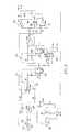
- Input signal 146is estimated patient flow, although it may alternatively be total flow. Use of estimated flow, in accordance with other aspects of the invention as described hereinabove, allows for further improved triggering if the system includes an unknown leak component.
- the input signal 146is differentiated by inverting differentiator 148.
- the diodes, switches and operational amplifier group indicated generally at 150are included for practical considerations. They form a switchable polarity ideal diode that is used to clip the large positive derivative of the flow trace at the beginning of inspiration, and the large negative derivative at the beginning of expiration. These derivatives are usually large, especially when ventilator pressure changes occur. If the large derivatives are not clipped, they can interfere with trigger circuit operation in the early part of each respiratory phase.
- the differentiated input signalis scaled by feedback resistor 152 and input capacitor 154. These have a time constant equal to 300 milliseconds which is a preferred delay time for the delay portion of the circuit.
- the series input resistor 156limits high frequency noise which is outside the range of breathing frequencies of interest.
- the differentiated input signalis subtracted from the flow signal in a difference amplifier 172 since the derivative circuit output is inverted and a sum is needed.
- the requisite delayis produced using two fifth order, switched capacitor Bessel low pass filters 158.
- the Bessel filterhas a linear phase shift with frequency which has the effect of providing a time delay. Since the time delay depends on the order of the filter as well as the frequency response, two filter sections are needed to provide a high enough cutoff frequency with the 300 millisecond time delay.
- the 300 millisecond delaywas determined experimentally. This value seems appropriate in that the time constants for respiratory muscle activity are on the order of 50 to 100 milliseconds. Thus, a delay longer than 50 to 100 milliseconds would be needed to intercept flow changes caused by changes in respiratory muscle activity.
- a 555 type timer chip 160is set up as a 1 kHz oscillator. Along with the RC combination 174 at the Filter input, element 160 controls the cutoff frequency of the switched capacitor filters 158. Finally, a comparator 162 with hysteresis, provided by input resistor 176 and feedback resistors 166 and 164, changes its state based on the difference between the input flow rate signal and the processed flowrate signal. There is a fixed hysteresis during the inspiratory phase caused by resistor 166. The hysteresis characteristic of the described circuit provides the negative offset during inspiration and the positive offset during expiration mentioned above.
- the hysteresisis initially greater than that during inspiration and is based on the magnitude of the flow signal as set by the current through resistor 164 and diode 178.
- the inverting amplifier 180has a gain of 10 so that it saturates when the flow signal is greater than 0.5 volts, which corresponds to a flow of 30 liters per minute.
- the hysteresisis therefore almost doubled during the initial part of the exhalation phase by virtue of the 100k resistor 164 in parallel with the 82k resistor 166, in contrast with the 82k resistor 166 acting alone during inspiration. That is, during exhalation the output of invertor 180 is positive. Therefore, diode 178 is forward biased and supplies current through resistor 164 in addition to that supplied by resistor 176.
- the hysteresisdecreases linearly with flow rate to be the same as that during inspiration. This feature prevents premature triggering to inspiration while gradually increasing the sensitivity of the system toward the end of exhalation.
- the hysteresisis somewhat dependent on the flow signal since it is supplied through a resistor 164. With the components described (82k feedback resistor 166, 1.5k input resistor 156) and a +5 volt system power supply (not shown), the hysteresis is about 90 millivolts at zero flow. This corresponds with a trigger offset of 90 cc per second above the instantaneous flow signal.
- Fig. 9illustrates operation of the flow trace shape trigger circuit with the heavy line 168 indicating the flow signal at the - input and the lighter line 170 indicating the processed flow signal at the + input to the system comparator 162.
- Line 170shows hysteresis decreasing as flow approaches zero during exhalation.
- Figs. 10A and 10Billustrate the behavior of two ventilator triggering algorithms when used in a simulation of a spontaneously breathing patient with a large respiratory time constant.
- the uppermost tracerepresents estimated patient flow
- the center tracerepresents patient respiratory effort
- the bottom tracerepresents ventilator pressure generated at the mask which interfaces with the patient airway.
- the letter Iindicates patient inspiratory effort in each respiratory cycle.
- Fig. 10Aillustrates the sorts of triggering problems which were described hereinabove and which have been known to occur with actual patients.
- Patient inspiratory effortdoes not consistently trigger the ventilator, as shown by the asynchrony between patient effort, the estimated patient flow, and pressure generated at the mask.
- Fig. 10Billustrates ventilator response to the same simulated patient using the above-described shape triggering algorithm, but with all other settings unchanged.
- a comparison of Fig. 10A with 10Breveals the improved synchronization of delivered pressure with spontaneous patient effort.
- Figs. 10A and 10Bexhibits significant exhalatory flow at the beginning of an inspiratory effort. From Fig. 10B, it may be clearly seen that the shape triggering algorithm triggers appropriately at the beginning and end of each and every inspiratory effort even though the inspiratory effort begins while there is still exhalatory flow. Thus, the shape triggering algorithm achieves the objective of synchronizing ventilator triggering with changes in patient effort.
- Figs. 11A and 11Bare similar to Figs. 10A and 10B, respectively, but the simulated patient has a shorter respiratory system time constant.
- Fig. 11Aillustrates, from top to bottom, estimated patient flow, patient respiratory effort, and pressure at the mask for a given triggering algorithm
- Fig. 11Billustrates the same parameters for the above-described flow trace shape triggering algorithm.
- Fig. 11Ait is clear that even with a substantial drop in flow when patient effort stops, the system does not trigger to EPAP until flow drops below about 25% of peak flow.
- the end of the inspiratory phaseis not synchronized with the end of patient inspiratory effort.
- the shape triggering algorithm of Fig. 11Bproduces, for the same patient, consistently synchronized triggering at the end of patient inspiratory effort.
- a ventilatorcan be triggered on the basis of changes in the shape of the flow signal which correspond to changes in patient respiratory effort.
- This triggering algorithmsolves several vexing problems which have limited the utility of some prior triggering algorithms such as standard pressure support triggering. It is also to be noted that the described flow signal shape triggering algorithm does not rely on any calculation of system leakage, although the shape triggering algorithm can operate more reliably with an estimate of system leakage than without it.
- the described shape triggering algorithmmay be used in parallel with the earlier described flow triggering algorithm to provide a dual triggering system in which a secondary triggering algorithm will function in the event the primary algorithm malfunctions.
- This sort of dual triggering systemcan operate on a continuing breath-to-breath basis such that at any desired trigger point the secondary triggering algorithm will trigger the ventilator if the primary triggering algorithm does not.
- leak compensation techniquesare also contemplated by this invention.
- the algorithm described thererelies on two requirements as follows: (1) the patient's inhaled and exhaled volumes over time are the same, (and indeed if the patient's rest volume just prior to the beginning of inspiration is the same from breath to breath, the inhaled and exhaled volumes for each individual breath will also be the same); (2) when the patient is inhaling, total flow is greater than leak flow and when the patient is exhaling total flow is less than leak flow.
- the leak componentitself can have two components, namely the known or intended leak of an exhalation port and an unknown leak component resulting from one or more inadvertent leaks such as leakage across a mask seal or at a tubing connection.
- the unknown or inadvertent leak componentwould be quite difficult to determine exactly as it can be a function of both pressure and time. Therefore, to the extent it is necessary to determine this leak component, its value is estimated; however, significant leak management improvements can also be developed without separating the leak into its intended and inadvertent components.
- the objectiveis still to adjust the estimate of leakage so that its average value is the same as the average value of the true leak over integral respiratory cycles.
- the average of the true leakcan be obtained as the average of total flow since the patient flow component of average total flow is zero.
- leakis a function of pressure, such as the leak from a WHISPER SWIVEL (tm) connector
- the leakwill likely be less at EPAP than it is at IPAP, with an average value corresponding to a pressure between EPAP and IPAP. That is, for a leak which is a function of pressure, the leakage rate at a lower pressure is less than the leakage rate at a higher pressure.
- This characteristic of leak flowcan be utilized in algorithms other than that described hereinabove to compensate for system leakage.
- the purpose of determining leakageis to thereby determine patient flow in an open system.
- a closed systemideally has no leaks, but in practice may have inadvertent leaks; however, in an open system gas flow from the system, whether by a regulated leak at an exhaust point or through inadvertent leaks from tubing connections and seal interfaces, will constitute a significant part of the total system flow.
- leakage in the patient circuit of an open systemcan be calculated by using the total flow as detected by a pneumotach.
- This parameterwhich we refer to as raw flow, includes all flow leaving or entering the gas flow source (eg., a blower) via the patient circuit. Therefore, raw flow includes both patient flow and system leakage.
- the purpose of the described leak management algorithmis to separate raw flow into patient flow and leakage components.
- a non-pressure dependent leakFor a non-pressure dependent leak, one first determines when patient inhalation begins. We refer to this point in the patient's respiratory cycle as a the breath trigger and use it as a reference point to compare patient inspiratory and expiratory volumes. By using the beginning of inspiration as a breath trigger point, the leakage calculation is done with the patient's beginning lung volume at approximately the same level for every calculation.
- the breath trigger reference pointis identified by satisfaction of two conditions as follows: (1) raw flow greater than average leak rate; and (2) patient is ready to inhale. Concerning the first of these conditions, the comparison of raw flow with average leak rate reveals whether the patient is inhaling or exhaling because, as noted above, the nature of the raw flow component is such that raw flow exceeds system leakage during patient inspiration and is less than system leakage during patient expiration.
- the second conditionthat of determining whether the patient is ready to inhale, is assessed by reference to either of two additional conditions as follows: (1) the patient has exhaled a predetermined fraction of the inhaled volume, for example 1/4 of inhalation volume; or (2) the patient has exhaled for more than a predetermined time, for example 300 milliseconds.
- An alternative statement of the first of these conditionsis that the patient's exhaled volume is at least a significant fraction of inspiratory volume.
- an exhalation time of more than 300 millisecondscan be detected by comparison of raw flow with estimated average leakage rate since, as noted above, raw flow is less than estimated average leak rate during exhalation.
- the seeming contradiction of requiring raw flow greater than average leak rate to satisfy one breath trigger condition, and raw flow less than average leak rate as one parameter that can satisfy the second breath trigger conditionis explained as follows.
- the condition that raw flow is greater than average leak ratemerely indicates that the patient has begun an inhalation cycle; that is, the patient has exerted the initial inspiratory effort that is revealed as raw flow exceeding average system leakage.
- the raw flow signalcan and does cross the average leak rate signal due to spurious noise in the raw flow signal, not all incidents of raw flow being greater than average leakage will denote the beginning of patient inspiratory effort.
- noise in the raw flow signalmay typically result in multiple crossings between the raw flow signal and the average leak signal. Especially troublesome in this regard is noise causing a momentary - to + transition while the actual major condition is the flow crossing zero due to a true inspiratory to expiratory transition.
- the additional ready-to-inhale conditionis imposed. Under this condition, the raw flow greater than average leak condition is validated only if one of the two conditions indicating the patient's respiration was just previously in an exhalatory state is satisfied. In the case of the second of these conditions, the 300 millisecond duration of raw flow less than average leakage corresponds to patient exhalation. Thus, the time element plays a role in the described breath trigger algorithm and must be understood. Raw flow less than average leakage indicates exhalation which then provides a ready-to-inhale output. A subsequent reversal of raw flow to a value greater than average leakage indicates the detection of patient inspiratory effort. The breath trigger thus consistently initiates an inspiratory cycle in synchronism with spontaneous patient respiration.
- the ready-to-inhale parameteris reset to await satisfaction of one of the two conditions specified above that provides a ready-to-inhale validation.
- the breath triggering processis then repeated upon occurrence of the next patient inspiratory effort when raw flow again exceeds average system leakage.
- the time interval between breath triggers from one breath to the nextcan be captured and the raw flow signal integrated over that time interval to find the raw volume or total volume for each breath.
- the raw volumemay then be divided by the time between breath triggers, for example the time interval between the next successive pair of breath triggers, to determine a recent time rate of leakage.
- the patient's respiration from one breath trigger to the nextrises from zero volume to a maximum value comprised of inspiratory volume and leakage volume during inspiration.
- the continued integration of negative flowreduces the raw volume parameter progressively as the exhaled volume is subtracted.
- the raw volume parameter from the prior breathis equal to only the leakage volume and any change in patient resting volume; however, this latter value generally is assumed to be zero.
- the raw volume parameteris really only leak volume
- dividing that value by the time duration of the breathprovides an estimate of the leak rate for the most recent breath.
- an average leak ratecan be determined to provide a more stable signal.
- the number of respiratory cycles over which the recent leak may be averaged to determine average leak ratemay be anywhere between one and infinity, depending upon the desired balance between signal stability and rapid error correction. Longer term averaging results in greater stability but slower error correction. Shorter term averaging provides less stability but quicker error correction.
- the average leak rate whose calculation is described herewas used initially in this algorithm in one of the conditions for initiating a breath trigger.
- the parameters used in the conditions for initiating a breath triggerthus can be continually updated, used to satisfy the breath trigger conditions, and then the successive breath triggers are used in turn to again update these parameters.
- a related approach to leakage analysisinvolves the use of a leak component which is, or is assumed to be, a function of patient circuit pressure.
- This sort of leak analysiscan be useful in such ventilation regimens as, for example, proportional assist ventilation such as described in U.S. patent 5,107,830 . It is important in proportional assist ventilation to know both the average leak rate and the instantaneous leak for the system.
- proportional assist ventilationinvolves variation of pressure according to the level of ventilation assistance required by the patient from moment to moment. Since at least some components of system leakage can be a function of pressure, those components will also vary more or less in synchronism with varying patient ventilation needs.
- Known leakagemay be any leak, intentional or otherwise, having known flow characteristics, for example the leakage through a WHISPER SWIVEL (tm) or through a plateau exhalation valve. That is, the known leak is not necessarily a fixed leak, but can also be a function of pressure. Although such leaks of known characteristics could be lumped together with leaks having unknown characteristics but assumed to be functions of pressure, the following analysis can be carried out with leaks of known characteristics included or excluded from the leakage calculation described.
- the pressure dependent leakis calculated as a function of system pressure from analysis of the raw flow signal.
- One function by which the pressure dependent leak component is related to pressureis that for any orifice defining a pressure drop between a pressurized system and a lower pressure surrounding environment, the flow through the orifice will be proportional to the square root of the pressure difference across the orifice multiplied by a constant K which characterizes the mechanical features of the orifice itself, that is its size, surface smoothness, and so forth.
- the breath trigger defined aboveis utilized to mark the beginning and end of patient respiratory cycles, and the average patient circuit pressure is measured for each breath.
- the average leak rateas calculated hereinabove, is multiplied by the time duration of the previous breath to determine pressure dependent leak volume on a per-breath basis. If the pressure dependent leak component is separated from the known leak component, then the known leak component is also separated from average leak rate before the average leak rate is used to determine pressure dependent leak volume.
- the pressure dependent leak volumeis then divided by the average of the square root of the pressure for the prior breath to give the corresponding orifice characteristic K. Over the next breath, the pressure dependent leak is found by multiplying the calculated orifice characteristic K by the square root of instantaneous pressure. This gives the pressure dependent leak rate as a function of pressure throughout the breath. This is an important parameter in such ventilation regimens as the above characterized proportional assist ventilation. More generally, however, it is important for the therapist to have reliable information on system leakage. The pressure dependent leak rate therefore can be useful for characterizing leakage in a variety ventilation systems.
- Initiation of the recovery algorithmis determined to be necessary if any one of four known physiological events occurs as follows: (1) exhalation continues for more than 5 seconds; (2) inhalation continues for more than 5 seconds; (3) inspiratory tidal volume is greater than 5 liters; or (4) expiratory tidal volume is less than -1 liter.
- the ventilator systemshould include elements for monitoring operation to detect occurrence of any one of these events.
- rediscovery of the leakis initiated by changing the average leak rate to the raw flow signal by gradually adding a percentage of the difference between raw flow and average leak to the average leak rate.
- the percentage of difference addedshould be selected to provide a time constant of approximately one second.
- the increasing average leak rateultimately will cause a breath trigger in accordance with one of the triggering algorithms as described above, and the repetitive leak calculations will then resume with each respiratory cycle.
- the algorithmmay also be based on comparison of estimated patient flow to a zero value, and calculate only an unknown leak as a function of pressure.
- a breath indicator or triggeris employed as a marker for the start of patient inspiration.
- the breath triggeroccurs when two conditions are met, namely: (1) estimated patient flow is greater than 0; and (2) patient is ready to inhale.
- the ready-to-inhale conditionis satisfied when: (1) the patient has exhaled a specified portion (eg. 25%) of inspiratory volume; (2) estimated patient flow is less than 0; and (3) inspiratory volume is greater than a constant represented by 0 or a small positive value.
- the conditions requiring inspiratory volume to be both less than a percentage of expiratory volume and greater than a small positive valueare not contradictory as these measurements are taken at different times.
- the ready-to-inhale conditionmust be satisfied by the specified parameters, including detection of an estimated patient flow less than zero since the last inhalation. Then, a breath trigger can occur when estimated patient flow goes positive since estimated patient flow greater than 0 indicates initial patient inhalatory effort.
- the unknown orificeis calculated by dividing the value obtained from raw flow integration by the value obtained from integration of the square root of pressure to provide the characteristic K for the unknown orifice.
- the unknown orificeis a hypothetical leak source intended to describe the characteristic of leakage from all sources of pressure dependent leak.
- the unknown orifice characteristicis multiplied by the square root of patient circuit pressure at any time during the following breath to provide a measure of the instantaneous unknown leak. Estimated patient flow is then found by subtracting the instantaneous unknown leak from the raw flow.
- K⁇ 0 T total flow ⁇ d ⁇ t ⁇ 0 T ⁇ Pressure ⁇ d ⁇ t
- the calculationscan be modified to provide greater accuracy by subtracting the known leak component from raw flow prior to integration of raw flow to determine the unknown orifice, and also prior to utilizing raw flow to determine estimated patient flow.
- the integral of raw flow minus the known leak, divided by the integral of the square root of patient circuit pressurewill provide the parameter K characterizing the unknown orifice attributable to only the unknown leak. That orifice characteristic K can then be multiplied by the square root of patient circuit pressure during the subsequent breath to provide a measure of the unknown leak component. Estimated patient flow at any time then would be found by subtracting both the known leak and the calculated unknown leak from the raw flow signal.
- the modified algorithmpreferably also includes a recovery routine for essentially the same reasons as earlier stated.
- a breath trigger for this modified algorithmdepends upon estimated patient flow crossing the zero value as the patient breaths. When the leak value changes, both raw flow and estimated patient flow will increase if the leak is increasing, or decrease if the leak is decreasing. It is possible for such an increase or decrease to be large enough that estimated patient flow will never cross the 0 value. When this occurs no breath trigger occurs and there will be no new or updated leak calculations unless a recovery routine is performed.
- a recovery algorithmmay be utilized to detect when leakage calculation is out of control according to two limiting parameters as follows: (1) inspiratory tidal volume is greater than a physiological value such as 4.5 liters; or (2) inspiratory tidal volume is less than a non-physiological value such as -1 liter.
- inspiratory tidal volumeis greater than a physiological value such as 4.5 liters; or (2) inspiratory tidal volume is less than a non-physiological value such as -1 liter.
- the data used for these continued calculationscan include data from after the change in leak magnitude so that the estimate of the unknown leak is improved. Even if the new unknown leak value is incorrect, continuing repeated calculations also will be based on data from after the change in leak magnitude. Thus, the calculated estimate of unknown leak will continue to quickly approach reliable values.
- Fig. 12illustrates the described leak management algorithm in action, with intentional introduction of a very large leak.
- the four tracesrepresent, from top to bottom, pressure, estimated patient flow, estimated inspiratory volume, and estimated leak (combined known and unknown leakage).
- the X axisis progressing time, moving from left to right.
- a very large leakwas introduced as indicated at point O on the estimated patient flow trace.
- the estimated patient flow and estimated inspiratory volumerise off scale very quickly.
- estimated inspiratory volumehas reached 4.5 liters and a breath trigger thus is forced.
- the resulting calculationestimates the leak to be a very high value which, in the estimated leak portion of Fig. 12 is off scale.
- the resulting estimated patient flowis approximately 50 liters per minute where in fact it should be zero. Tidal volume continues to rise rapidly as indicated at point 3 and would ultimately force another breath trigger when it reached the 4.5 liter limit.
- the large system leakis removed at time T', however, so the rise in tidal volume ceases.
Landscapes
- Health & Medical Sciences (AREA)
- Emergency Medicine (AREA)
- Pulmonology (AREA)
- Engineering & Computer Science (AREA)
- Anesthesiology (AREA)
- Biomedical Technology (AREA)
- Heart & Thoracic Surgery (AREA)
- Hematology (AREA)
- Life Sciences & Earth Sciences (AREA)
- Animal Behavior & Ethology (AREA)
- General Health & Medical Sciences (AREA)
- Public Health (AREA)
- Veterinary Medicine (AREA)
- Measurement Of The Respiration, Hearing Ability, Form, And Blood Characteristics Of Living Organisms (AREA)
- Pharmaceuticals Containing Other Organic And Inorganic Compounds (AREA)
- Investigating Or Analysing Biological Materials (AREA)
Description
- The sleep apnea syndrome, and in particular obstructive sleep apnea, afflicts an estimated 4% to 9% of the general population and is due to episodic upper airway obstruction during sleep. Those afflicted with obstructive sleep apnea experience sleep fragmentation and intermittent, complete or nearly complete cessation of ventilation during sleep with potentially severe degrees of oxyhemoglobin unsaturation. These features may be translated clinically into debilitating daytime sleepiness, cardiac disrhythmias, pulmonary-artery hypertension, congestive heart failure and cognitive dysfunction. Other sequelae of sleep apnea include right ventricular dysfunction with cor pulmonale, carbon dioxide retention during wakefulness as well as during sleep, and continuous reduced arterial oxygen tension. Hypersomnolent sleep apnea patients may be at risk for excessive mortality from these factors as well as from an elevated risk for accidents such as while driving or operating other potentially dangerous equipment.
- Although details of the pathogenesis of upper airway obstruction in sleep apnea patients have not been fully defined, it is generally accepted that the mechanism includes either anatomic or functional abnormalities of the upper airway which result in increased air flow resistance. Such abnormalities may include narrowing of the upper airway due to suction forces evolved during inspiration, the effect of gravity pulling the tongue back to appose the pharyngeal wall, and/or insufficient muscle tone in the upper airway dilator muscles. It has also been hypothesized that a mechanism responsible for the known association between obesity and sleep apnea is excessive soft tissue in the anterior and lateral neck which applies sufficient pressure on internal structures to narrow the airway.
- The treatment of sleep apnea has included such surgical interventions as uvalopalatopharyngoplasty, gastric surgery for obesity, and maxillo-facial reconstruction. Another mode of surgical intervention used in the treatment of sleep apnea is tracheostomy. These treatments constitute major undertakings with considerable risk of post-operative morbidity if not mortality. Pharmacologic therapy has in general been disappointing, especially in patients with more than mild sleep apnea. In addition, side effects from the pharmacologic agents that have been used are frequent. Thus, medical practitioners continue to seek non-invasive modes of treatment for sleep apnea with high success rates and high patient compliance including, for example in cases relating to obesity, weight loss through a regimen of exercise and regulated diet.
- Recent work in the treatment of sleep apnea has included the use of continuous positive airway pressure (CPAP) to maintain the airway of the patient in a continuously open state during sleep. For example,
U.S. patent 4,655,213 and Australian patentAU-B-83901/82 - Also of interest is
U.S. patent 4,773,411 which discloses a method and apparatus for ventilatory treatment characterized as airway pressure release ventilation and which provides a substantially constant elevated airway pressure with periodic short term reductions of the elevated airway pressure to a pressure magnitude no less than ambient atmospheric pressure. - Publications pertaining to the application of CPAP in treatment of sleep apnea include the following:
- 1.Lindsay, DA, Issa FG, and Sullivan C.E. "Mechanisms of Sleep Desaturation in Chronic Airflow Limitation Studied with Nasal Continuous Positive Airway Pressure (CPAP)", Am Rev Respir Dis, 1982; 125: p.112.
- 2.Sanders MH, Moore SE, Eveslage J. "CPAP via nasal mask: A treatment for occlusive sleep apnea", Chest, 1983; 83: pp. 144-145.
- 3.Sullivan CE, Berthon-Jones M, Issa FG. "Remission of severe obesity-hypoventilation syndrome after short-term treatment during sleep with continuous positive airway pressure", Am Rev Respir Dis, 1983; 128: pp. 177-181.
- 4.Sullivan CE, Issa FG, Berthon-Jones M, Eveslage. "Reversal of obstructive sleep apnea by continuous positive airway pressure applied through the nares", Lancet, 1981; 1: pp. 862-865.
- 5.Sullivan CE, Berthon-Jones M. Issa FG. "Treatment of obstructive apnea with continuous positive airway pressure applied through the nose", Am Rev Respir Dis, 1982; 125: p.107. Annual Meeting Abstracts.
- 6.Rapoport DM, Sorkin B, Garay SM, Goldring RM. "Reversal of the 'Pickwickian Syndrome' by long-term use of nocturnal nasal-airway pressure", N Engl J. Med, 1982; 307: pp.931-933.
- 7.Sanders MH, Holzer BC, Pennock BE. "The effect of nasal CPAP on various sleep apnea patterns", Chest, 1983; 84: p.336.
- Although CPAP has been found to be very effective and well accepted, it suffers from some of the same limitations, although to a lesser degree, as do the surgical options; specifically, a significant proportion of sleep apnea patients do not tolerate CPAP well. Thus, development of other viable non-invasive therapies has been a continuing objective in the art.
- The present invention may be used in a novel and improved method for treatment of sleep apnea and concerns an apparatus for carrying out such improved treatment method. The invention contemplates the treatment of sleep apnea through application of pressure at variance with ambient atmospheric pressure within the upper airway of the patient in a manner to promote dilation of the airway to thereby relieve upper airway occlusion during sleep.
- In one embodiment of the invention, positive pressure is applied alternately at relatively higher and lower pressure levels within the airway of the patient so that the pressure-induced force applied to dilate the patient's airway is alternately a larger and a smaller magnitude dilating force. The higher and lower magnitude positive pressures are initiated by spontaneous patient respiration with the higher magnitude pressure being applied during inspiration and the lower magnitude pressure being applied during expiration.
- The invention further contemplates a novel and improved apparatus as defined in
claim 1 which is operable in accordance with a novel and improved method to provide sleep apnea treatment. More specifically, a flow generator and an adjustable pressure controller supply air flow at a predetermined, adjustable pressure to the airway of a patient through a flow transducer. The flow transducer generates an output signal which is then conditioned to provide a signal proportional to the instantaneous flow rate of air to the patient. In an embodiment the instantaneous flow rate signal is fed to a low pass filter which passes only a signal indicative of the average flow rate over time. The average flow rate signal typically would be expected to be a value representing a positive flow as the system is likely to have at least minimal leakage from the patient circuit (e.g. small leaks about the perimeter of the respiration mask worn by the patient). The average flow signal is indicative of leakage because the summation of all other components of flow over time must be essentially zero since inspiration flow must equal expiration flow volume over time, that is, over a period of time the volume of air breathed in equals the volume of the gases breathed out. - Both the instantaneous flow signal and the average flow rate signal are fed to an inspiration/expiration decision module which is, in its simplest form, a comparator that continually compares the input signals and provides a corresponding drive signal to the pressure controller. In general, when the instantaneous flow exceeds average flow, the patient is inhaling and the drive signal supplied to the pressure controller sets the pressure controller to deliver air, at a preselected elevated pressure, to the airway of the patient. Similarly, when the instantaneous flow rate is less than the average flow rate, the patient is exhaling and the decision circuitry thus provides a drive signal to set the pressure controller to provide a relatively lower magnitude of pressure in the airway of the patient. The patient's airway thus is maintained open by alternating higher and lower magnitudes of pressure which are applied during spontaneous inhalation and exhalation, respectively.
- As has been noted, some sleep apnea patients do not tolerate standard CPAP therapy. Specifically, approximately 25% of patients cannot tolerate CPAP due to the attendant discomfort. CPAP mandates equal pressures during both inhalation and exhalation. The elevated pressure during both phases of breathing may create difficulty in exhaling and the sensation of an inflated chest. However, we have determined that although both inspiratory and expiratory air flow resistances in the airway are elevated during sleep preceding the onset of apnea, the airway flow resistance may be less during expiration than during inspiration. Thus it follows that the bi-level CPAP therapy as characterized above may be sufficient to maintain pharyngeal patency during expiration even though the pressure applied during expiration is not as high as that needed to maintain pharyngeal patency during inspiration. In addition, some patients may have increased upper airway resistance primarily during inspiration with resulting adverse physiologic consequences. Thus, our invention also contemplates applying elevated pressure only during inhalation thus eliminating the need for global (inhalation and exhalation) increases in airway pressure. The relatively lower pressure applied during expiration may in some cases approach or equal ambient pressure. The lower pressure applied in the airway during expiration enhances patient tolerance by alleviating some of the uncomfortable sensations normally associated with CPAP.
- Under prior CPAP therapy, pressures as high as 20 cm H20 (1cm H20 = 100Pa) have been required, and some patients on nasal CPAP thus have been needlessly exposed to unnecessarily high expiratory pressures with the attendant discomfort and elevated mean airway pressure, and theoretic risk of barotrauma. In an embodiment Our invention permits independent application of a higher inspiratory airway pressure in conjunction with a lower expiratory airway pressure in order to provide a therapy which is better tolerated by the 25% of the patient population which does not tolerate CPAP therapy, and which may be safer in the other 75% of the patient population.
- As has been noted hereinabove, the switch between higher and lower pressure magnitudes can be controlled by spontaneous patient respiration, and the patient thus is able to independently govern respiration rate and volume. As has been also noted, the invention contemplates automatic compensation for system leakage whereby nasal mask fit and air flow system integrity are of less consequence than in the prior art. In addition to the benefit of automatic leak compensation, other important benefits of the invention include lower mean airway pressures for the patient and enhanced safety, comfort and tolerance.
- A further object of the invention to provide a novel and improved apparatus which is operable according to a novel methodology in carrying out such a treatment for sleep apnea.
- Another object of the invention is to provide an apparatus for generating alternately high and low pressure gas flow to a consumer of the gas with the higher and lower pressure flows being controlled by comparison of the instantaneous flow rate to the gas consumer with the average flow rate to the consumer, which average flow rate may include leakage from the system, and whereby the apparatus automatically compensates for system leakage.
- These and other objects and further advantages of the invention will be more readily appreciated upon consideration of the following detailed description and accompanying drawings, in which:
- Fig. 1 is a functional block diagram of an apparatus which may be operable according to the instant invention;
- Fig. 2 is a functional block diagram showing an alternative embodiment of the invention;
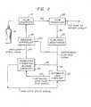
- Fig. 3 is a functional block diagram of the Estimated Leak Computer of Fig. 2;
- Fig. 4 is a frontal elevation of a control panel for the apparatus of this invention;
- Fig. 5 is a trace of patient flow rate versus time pertaining to another embodiment of the invention;
- Fig. 6 is a flow diagram relating to the embodiment of Fig. 5;
- Fig. 7 is a trace of patient flow rate versus time illustrating another embodiment of the invention;
- Fig. 8 is a schematic illustration of a circuit according to an embodiment of the invention;
- Fig. 9 is a trace of flow rate versus time showing processed and unprocessed flow rate signals;
- Figs. 10a and 10b are illustrations of the operation of control algorithms according to other embodiments of the invention;
- Figs. 11a and 11b are illustrations of the operation of still other control algorithms according to other embodiments of the invention; and
- Fig. 12 illustrates operation of yet another control algorithm according to an embodiment of the invention.
- Figs. 1 to 4 of the drawings are taken from our own
EP-A-425092 - Not all of the circuits shown in the figures belong to the invention.
- An alternative embodiment of the invention contemplates detecting the beginning of inspiration and expiration by reference to a patient flow rate wave form such as shown in Fig. 5. Comparison of instantaneous flow rate with average flow rate as set forth hereinabove provides a satisfactory method for determining whether a patient is inhaling or exhaling; however, other means for evaluating instantaneous flow rate can also be used, and these may be used alone or in combination with average flow rate.
- For example, Fig. 5 shows a typical patient flow rate wave form with inspiration or inhalation flow shown as positive flow above base line B and exhalation flow shown as negative flow below base line B. The flow rate wave form may thus be sampled at discrete time intervals. The current sample is compared with that taken at an earlier time. This approach appears to offer the benefit of higher sensitivity to patient breathing effort in that it exhibits less sensitivity to errors in the estimated system leakage, as discussed hereinabove.
- Normally, the estimated inspiratory and expiratory flow rate wave forms will change slowly during the period beginning after a few hundred milliseconds into the respective inspiratory and expiratory phases, up until the respective phase is about to end. Samples of the flow rate wave form are taken periodically, and the current sample is compared repeatedly with a previous sample. During inspiration, if the magnitude of the current sample is less than some appropriate fraction of the comparison sample, then the inspiration phase is deemed to be finished. This condition thus can be used to trigger a change to the desired exhalation phase pressure. The same process can be used during exhalation to provide a trigger condition for the changeover to inhalation pressure.
- Fig. 6 illustrates a flow diagram for a suitable algorithm showing repeated sampling of the patient flow rate wave form at time intervals Δt, as shown at 110, and repeated comparison of the flow at current time t with a prior sampling, for example the flow at time t-4 as indicated at 112. Of course, the time increment between successive samplings is small enough that the comparison with the value observed in the fourth prior sampling event covers a suitably small portion of the flow rate wave form. For example, as shown in Fig. 5 the designations for flow sampled at time t, the sample value taken four sampling events prior at time t-4, and the time interval Δt illustrate one suitable proportionate relationship between Δt and the time duration of a patient breath. This is, however, only an illustration. In fact, electronic technology such as disclosed hereinabove would be capable of performing this algorithm using much smaller Δt intervals, provided other parameters of the algorithm, such as the identity of the comparison sample and/or the proportion relationship between the compared samples, are adjusted accordingly.
- Continuing through the flow chart of Fig. 6, if the patient's state of breathing is inspiration (114), the current flow sample value is compared with the sample value observed t-4 sampling events prior. If the current flow sample value is less than, for example, 75% of the comparison flow value (116), the system triggers a change in state to the exhalation phase (118). If the current flow sample value is not less than 75% of the comparison value (120), no change in breathing state is triggered.
- If the breathing state is not inspiration, and the current flow sample value is less than 75% of the selected comparison value (122), then an expiration phase, rather than an inspiration phase, is completed and the system is triggered to change the state of breathing to inspiration (124). If the specified flow condition is not met, again no change in breathing phase is triggered (126).
- The routine characterized by Fig. 6 repeats continuously as indicated at 128, each time comparing a current flow sample with the fourth (or other suitable) prior sample to determine whether the system should trigger from one breathing phase to the other.
- Of course, it will be understood that the embodiment set forth above with reference to Figs. 5 and 6 does not trigger changes in breathing per se within the context of the invention as set forth in the balance of the above specification. Rather, in that context the Fig. 5 and 6 embodiment merely detects changes between inspiration and expiration in spontaneous patient breathing, and triggers the system to supply the specified higher or lower airway pressure as set forth hereinabove.
- Common problems resulting from insufficient ventilator triggering sensitivity include failure of the ventilator to trigger to IPAP upon exertion of inspiratory effort by the patient, and failure of the ventilator in IPAP to trigger off or to EPAP at the end of patient inspiratory effort. Patient respiratory effort relates primarily to the inspiratory portion of the respiration cycle because in general only the inspiratory part of the cycle involves active effort. The expiratory portion of the respiration cycle generally is passive. A further characteristic of the respiratory cycle is that expiratory flow rate generally may reach zero and remain at zero momentarily before the next inspiratory phase begins. Therefore the normal stable state for a patient-triggered ventilator should be the expiratory state, which is referred to herein as EPAP.
- Although the apparatus as above described provides sensitive triggering between the IPAP and EPAP modes, triggering can be still further improved. The primary objectives of improvements in triggering sensitivity generally are to decrease the tendency of a system to trigger automatically from EPAP to IPAP in the absence of inspiratory effort by the patient, and to increase system sensitivity to the end of patient inspiratory effort. These are not contradictory objectives. Decreasing auto-trigger sensitivity does not necessarily also decrease triggering sensitivity to patient effort.
- Generally, for a patient whose ventilatory drive is functioning normally, the ideal ventilator triggering sensitivity is represented by close synchronization between changes of state in the patient's respiration (between inspiration and expiration), and the corresponding changes of state by the ventilator. Many conventional pressure support ventilators which trigger on the basis of specified flow or pressure thresholds can approach such close synchronization only under limited conditions.
- In the system described hereinabove, where triggering is based on specified levels of estimated patient flow rate, close synchronization between system state changes and patient respiration state changes can be readily achieved. This is especially true for patients having no severe expiratory flow limitation as the flow rate reversals for such patients typically may correspond quite closely with changes in the patient respiratory effort; however, flow rate reversals may not necessarily correspond precisely to changes in patient respiratory effort for all patients. For example, those patients experiencing respiratory distress or those being ventilated with pressure support ventilation may not exhibit the desired close correspondence between patient effort and breathing gas supply flow rate reversals.
- In addressing improvements in synchronized triggering based on flow rate, at least three different respiratory cycles are considered. The first is the patient respiratory cycle as indicated by patient effort. If the patient makes any effort, it must include inspiratory effort. Patient expiration may be active or passive.
- The second cycle is the ventilator respiratory cycle, that is, the cycle delivered by the ventilator. This cycle also has an inspiratory phase and an expiratory phase, but the ventilator may or may not be synchronized with the corresponding phases of the patient respiratory cycle.
- The third cycle is the flow respiratory cycle, as indicated by the direction of flow to or from the patient's airway. Flow passes from the ventilator into the patient on inspiration and out of the patient on expiration. If one looks at this cycle only, the inspiratory/expiratory changes could be identified by the zero flow crossings between positive and negative flow.
- Ideally, if the patient's breathing drive is competent, the flow respiratory cycle should be synchronized with the patient respiratory cycle, with the assistance of the ventilator. One important objective of the triggering described here is to synchronize the ventilator cycle with the patient cycle so that the flow cycle is coordinated with patient inspiratory effort. With flow triggering the pressure delivered by the ventilator affects the flow, in addition to the effect on flow of the patient's own efforts. This is another reason why zero flow crossings may not necessarily be good indicators of changes in patient effort.
- As described, flow triggering provides certain advantages not available with some other modes of ventilator triggering. For example, in ventilators which use pressure variation for triggering, when the patient makes an inspiratory effort lung volume begins to increase. This volume change causes a pressure drop, which in some conventional closed circuit ventilators is sensed by the ventilator triggering system to initiate breathing gas delivery. With flow triggering there is no need for a pressure drop to occur in the breathing circuit. The triggering algorithm may still require the patient lung volume to increase, but since the pressure in the ventilator circuit does not have to drop the patient expends less energy in the inspiratory effort to achieve a given volume change.
- Additionally, in an open circuit, that is one in which exhaled gases are flushed from the system via a fixed leak, it would be difficult to generate the required pressure drop for pressure based triggering upon exertion of small patient inspiratory effort. That is, with an open circuit the magnitude of patient effort required to generate even a very small pressure drop would be considerable. Thus, it would be correspondingly quite difficult to achieve sufficient sensitivity in a pressure based triggering system to provide reliable triggering if used in conjunction with an open circuit. In general, the open circuit is simpler than one with a separate exhaust valve and exhaust tubing and therefore simpler to use and less costly, and for these and other reasons may often be preferred over a closed circuit.
- In a presently preferred triggering scheme for the above described flow rate triggering system, the flow rate signal must exceed a threshold value equivalent to 40 cc per second continuously for 35 milliseconds in order to trigger the system to IPAP. If the flow rate signal drops below the specified threshold value during the specified time interval, the threshold timer is reset to zero. These threshold values permit triggering with a minimal patient volume change of only 1.4 cc, which represents much improved sensitivity over some prior pressure triggered ventilators.
- In reality, however, such minimal patient volume change represents overly sensitive triggering which would not be practical in actual practice. Noise in the flow rate signal would continually reset the threshold timer during intervals when the patient flow rate is very close to 40 cc per second. Therefore, it is believed a minimum volume change for consistent triggering of the described system would be about 3 cc., although this too is considered to be a very sensitive triggering level. It is noted, however, that pressure signal noise can also occur in prior pressure triggered ventilators, thus creating triggering sensitivity problems. Due to this and other details of their operation the theoretical maximum sensitivity of such prior ventilators is better than the sensitivity which can actually be achieved in operation.
- As one example of an operating detail which can adversely affect sensitivity in prior ventilators, if the ventilator response time is slow, the resulting time delay between the time when a triggering time requirement is satisfied and the time when gas supply pressure actually begins to rise will adversely affect sensitivity. During the time delay, the patient is continuing to make inspiratory effort and thus will be doing much greater actual work than that needed to trigger the ventilator, and much greater work than would be done if the ventilator responded more quickly. Another example occurs during rapid breathing when a patient begins to make an inspiratory effort before exhalation flow rate drops to zero. In this case, an additional delay occurs until flow reverses and the exhalation valve has time to close.
- Triggering to EPAP upon exhalation also can present problems. A typical prior pressure support ventilator will trigger off at the end of inspiration based on the patient's flow decreasing past a flow threshold, or on timing out of a timer, for example. The trigger-to-exhalation flow threshold can be either a fixed value or a fraction of peak flow, for example 25% of peak flow. As one example of the sort of problem which can affect triggering to exhalation in prior ventilators, a patient with moderately severe COPD (chronic obstructive pulmonary disease) will exhibit comparatively high respiratory system resistance and perhaps low respiratory system elastance. This will result in a comparatively long time constant for the patient, the time constant being the time taken for exhalation flow to decay to 1/4 of peak flow or other suitable selected proportion of peak flow. The long time constant for the COPD patient means that flow will drop slowly during inspiration.
- The only way this patient will be able to trigger the ventilator to exhalation will be to increase exhalatory effort. That is, the patient must actively decrease the flow rate by respiratory muscle effort to trigger to exhalation. Further, because of the patient's large time constant, there may be considerable exhalation flow when the patient's inspiratory cycle begins, and the trigger to IPAP thus will be delayed, to the detriment of ventilator sensitivity.
- To achieve greater sensitivity to patient effort in an improved embodiment of the invention, the disclosed system may be provided with apparatus to continually monitor multiple conditions rather than monitoring only a single condition as represented by the description in
EP-A-425092 element 82. In the improved embodiment, inspiratory time is limited to no more than about 3 seconds under normal conditions, and normal exhalation flow rate is required to be nearly zero by about 5 seconds after the beginning of exhalation. - To employ the first of these conditions the system monitors estimated patient flow rate and requires its value to cross zero at least once approximately every 5 seconds. To monitor this condition, an input is required from the output of a comparator which compares patient flow rate with a zero value. The comparator is a bistable device which provides one output (i.e. true) when patient flow is greater than zero, and an alternative output (i.e. false) when patient flow is less than zero. If the comparator output is either true or false continuously for longer than about 5 seconds, a signal is generated which triggers the system to EPAP.
- The second condition is the monitoring of the IPAP/EPAP state to see if it remains in EPAP for more than about 5 seconds. If it does, the volume will be held at zero until there is another valid trigger to IPAP. This function prevents the volume signal from drifting away from zero when there is an apnea. After 5 seconds in EPAP volume should normally be zero.
- Further improvements in triggering sensitivity require consideration of more than flow rate levels for determination of suitable triggering thresholds. In particular, changes in the shape or slope of the patient's flow rate wave form can be utilized to better synchronize a ventilation system with spontaneous respiratory effort exerted by the patient. Some such considerations are discussed hereinabove with reference to Figs. 5 and 6.
- A typical flow rate tracing for a normal patient experiencing relaxed breathing is shown in Fig. 7. The simplest approach for synchronizing ventilator triggering to spontaneous patient respiration has often been to use the zero flow points 129 as the reference for triggering between EPAP and IPAP; however, this approach does not address the potential problems. First, as noted above, flow rate reversals may not necessarily correspond to changes in patient spontaneous breathing effort for all patients. Second, the flow signal is not necessarily uniform. Concerning this problem in particular, small flow variations corresponding to noise in electronic signals will occur due to random variations in system and airway pressure caused by flow turbulence or random variations in the pressure control system. Additional flow rate noise results from small oscillations in the breathing gas flow rate due to changes in blood volume within the patient's chest cavity with each heart beat. Third, since pressure support commonly is an all-or-nothing mode of ventilation, and since the respiratory systems of all patients will exhibit an elastance component, an inappropriate trigger to IPAP will always result in delivery of some volume of breathing gas unless the patient's airway is completely obstructed. Thus, reliance on zero flow or flow reversals for triggering will in many instances result in loss of synchronization between a patient inspiratory effort and ventilator delivery of breathing gas.
- Referring to Fig. 7, there is shown a flow rate versus time trace for the respiratory flow of a typical, spontaneously breathing person. Time advances from left to right on the horizontal axis and flow rate varies about a zero-value base line on the vertical axis. Of course, in the description below referring to Fig. 7 it is to be understood that the illustrated flow rate versus time trace is an analog for spontaneous breathing by a patient and for any detectors or sensors, whether based on mechanical, electronic or other apparatus, for detecting patient flow rate as a function of time.
- It will be noted on reference to Fig. 7 that relatively sharp breaks or slope changes occur in the flow rate trace when patient inhalation effort begins and ends. Thus, although the slope of the flow rate trace may vary widely from patient to patient depending on the patient resistance and elastance, for any given patient it will tend to be relatively constant during inhalation and exhalation. The relatively sudden increase in flow trace slope when an inspiratory effort begins, and a corresponding sudden decrease in slope when inspiratory effort ends, can be used to identify IPAP and EPAP trigger points. Since the abrupt changes in flow trace slope at the beginning and end of inhalation correspond with the beginning and end of inspiratory effort, the flow trace slope or shape may be used to trigger the system between the IPAP and EPAP state in reliance on changes in patient effort rather than on relatively fixed flow thresholds.
- The basic algorithm for operation of this further improved triggering system is as follows. The input to the system is the current flow rate at any point on the flow trace, for
example point 130 in Fig. 7. The flow value is differentiated to get the correspondingcurrent slope 132 of the flow function at time T. Of course, the slope corresponds to the instantaneous rate of change of flow rate. - The
slope 132 is scaled by a time factor Δt, and is then added to the current flow value. This gives a prediction of theflow 134 at a future time t+ Δt, based on thecurrent slope 132 of the flow trace. As noted, the magnitude of time interval Δt is determined by the selected scale factor by whichslope 132 is scaled. The resultingflow prediction 134 assumes, effectively, a uniform rate of change for the flow throughout the period Δt. It will be understood that in Fig. 7 the magnitude of time intervals Δt is exaggerated, and is different for the end of inspiration and beginning of inspiration changes, to facilitate clear illustration. In practice, Δt may be approximately 300 milliseconds, for example. - The accuracy of the predicted future
flow rate value 134 will depend upon the actual, varying slope of the flow trace during time interval Δt as compared to the presumeduniform slope 132. To the extent that the flow trace during interval Δt deviates fromslope 132, theactual flow value 136 at the end of time interval Δt will vary from the predictedflow value 134. Accordingly, it may be seen that the effectiveness of this algorithm depends upon the actual deviation in the flow trace fromslope 132 during any given Δt time interval being small except when the patient makes a significant change in respiratory effort. - To further modify the predicted
flow 134, an offset factor may be added to it to produce an offset predictedvalue 138. The offset is negative during inspiration so that the predicted flow at time t+ Δt will be held below the actual flow at t+Δt except when the flow trace changes in the decreasing flow direction, such as would occur at the end of inspiration when patient effort ceases or even reverses. - The above description refers to an end-of-inspiration trigger to EPAP. In an entirely similar fashion, as indicated generally at 140 in Fig. 7, a trigger to IPAP can be governed by prediction of a future flow rate based on differentiation of an
instantaneous flow rate 139 plus an offset factor to provide a predictedflow rate value 142. It is noted that in this instance the offset factor will be a positive offset since it is an abruptly increasing flow rate that one would wish to detect. In this instance, when actual flow rate increases sufficiently during the Δt interval to exceed predictedvalue 142, for example as indicated at 144, the system will trigger to IPAP. Thus, at any point in the flow cycle when actual flow after a predetermined time interval Δt differs sufficiently from the predicted, offset flow value based on flow trace slope at time T, the system is triggered to IPAP or EPAP depending upon the direction, either positive or negative, in which actual flow varies from the predicted flow. - The flow rate prediction based on current flow trace slope, and the comparison of the predicted flow rate with actual flow rate as described, is repeated at a high rate to generate a continuous or nearly continuous stream of actual flow-to-predicted flow comparisons. For example, in an analog system the process is continuous, while in a digital system the process is repeated every 10 milliseconds or faster. In the resulting locus of predicted flow value points, most actual-to-predicted flow comparisons do not result in triggering because actual flow rate does not deviate sufficiently from the predicted rate. Only at the inspiratory/expiratory changes does this occur. The result is a triggering method which, because it is based on flow predictions, does not require changes in patient inspiratory effort to achieve triggering in synchronism with spontaneous patient respiration. Of course, the described differentiation technique of flow prediction is but one example of a suitable flow wave shape triggering algorithm.
- A schematic diagram of one analog circuit embodying elements of the above-described improved trigger system is shown in Fig. 8.
Input signal 146 is estimated patient flow, although it may alternatively be total flow. Use of estimated flow, in accordance with other aspects of the invention as described hereinabove, allows for further improved triggering if the system includes an unknown leak component. Theinput signal 146 is differentiated by invertingdifferentiator 148. The diodes, switches and operational amplifier group indicated generally at 150 are included for practical considerations. They form a switchable polarity ideal diode that is used to clip the large positive derivative of the flow trace at the beginning of inspiration, and the large negative derivative at the beginning of expiration. These derivatives are usually large, especially when ventilator pressure changes occur. If the large derivatives are not clipped, they can interfere with trigger circuit operation in the early part of each respiratory phase. - The differentiated input signal is scaled by
feedback resistor 152 andinput capacitor 154. These have a time constant equal to 300 milliseconds which is a preferred delay time for the delay portion of the circuit. Theseries input resistor 156 limits high frequency noise which is outside the range of breathing frequencies of interest. The differentiated input signal is subtracted from the flow signal in adifference amplifier 172 since the derivative circuit output is inverted and a sum is needed. - The requisite delay is produced using two fifth order, switched capacitor Bessel low pass filters 158. The Bessel filter has a linear phase shift with frequency which has the effect of providing a time delay. Since the time delay depends on the order of the filter as well as the frequency response, two filter sections are needed to provide a high enough cutoff frequency with the 300 millisecond time delay. The 300 millisecond delay was determined experimentally. This value seems appropriate in that the time constants for respiratory muscle activity are on the order of 50 to 100 milliseconds. Thus, a delay longer than 50 to 100 milliseconds would be needed to intercept flow changes caused by changes in respiratory muscle activity.
- A 555
type timer chip 160 is set up as a 1 kHz oscillator. Along with theRC combination 174 at the Filter input,element 160 controls the cutoff frequency of the switched capacitor filters 158. Finally, acomparator 162 with hysteresis, provided byinput resistor 176 andfeedback resistors resistor 166. The hysteresis characteristic of the described circuit provides the negative offset during inspiration and the positive offset during expiration mentioned above. - During the expiratory phase, the hysteresis is initially greater than that during inspiration and is based on the magnitude of the flow signal as set by the current through
resistor 164 anddiode 178. The invertingamplifier 180 has a gain of 10 so that it saturates when the flow signal is greater than 0.5 volts, which corresponds to a flow of 30 liters per minute. The hysteresis is therefore almost doubled during the initial part of the exhalation phase by virtue of the100k resistor 164 in parallel with the82k resistor 166, in contrast with the82k resistor 166 acting alone during inspiration. That is, during exhalation the output ofinvertor 180 is positive. Therefore,diode 178 is forward biased and supplies current throughresistor 164 in addition to that supplied byresistor 176. - Once the flow signal drops below the 0.5 volt level, the hysteresis decreases linearly with flow rate to be the same as that during inspiration. This feature prevents premature triggering to inspiration while gradually increasing the sensitivity of the system toward the end of exhalation. The hysteresis is somewhat dependent on the flow signal since it is supplied through a
resistor 164. With the components described (82k feedback resistor 166, 1.5k input resistor 156) and a +5 volt system power supply (not shown), the hysteresis is about 90 millivolts at zero flow. This corresponds with a trigger offset of 90 cc per second above the instantaneous flow signal. - Fig. 9 illustrates operation of the flow trace shape trigger circuit with the
heavy line 168 indicating the flow signal at the - input and thelighter line 170 indicating the processed flow signal at the + input to thesystem comparator 162.Line 170 shows hysteresis decreasing as flow approaches zero during exhalation. - The triggering algorithm described immediately above is referred to as shape triggering (i.e. relying on changes in the shape or slope of the flow trace) to distinguish it from the flow triggering algorithm described earlier. Figs. 10A and 10B illustrate the behavior of two ventilator triggering algorithms when used in a simulation of a spontaneously breathing patient with a large respiratory time constant. In each of Figs. 10A and 10B, the uppermost trace represents estimated patient flow, the center trace represents patient respiratory effort, and the bottom trace represents ventilator pressure generated at the mask which interfaces with the patient airway. The letter I indicates patient inspiratory effort in each respiratory cycle.
- As may be seen, Fig. 10A illustrates the sorts of triggering problems which were described hereinabove and which have been known to occur with actual patients. Patient inspiratory effort does not consistently trigger the ventilator, as shown by the asynchrony between patient effort, the estimated patient flow, and pressure generated at the mask. Fig. 10B, by contrast, illustrates ventilator response to the same simulated patient using the above-described shape triggering algorithm, but with all other settings unchanged. A comparison of Fig. 10A with 10B reveals the improved synchronization of delivered pressure with spontaneous patient effort.
- It is noted that the simulated patient on which Figs. 10A and 10B are based exhibits significant exhalatory flow at the beginning of an inspiratory effort. From Fig. 10B, it may be clearly seen that the shape triggering algorithm triggers appropriately at the beginning and end of each and every inspiratory effort even though the inspiratory effort begins while there is still exhalatory flow. Thus, the shape triggering algorithm achieves the objective of synchronizing ventilator triggering with changes in patient effort.
- Figs. 11A and 11B are similar to Figs. 10A and 10B, respectively, but the simulated patient has a shorter respiratory system time constant. Fig. 11A illustrates, from top to bottom, estimated patient flow, patient respiratory effort, and pressure at the mask for a given triggering algorithm, and Fig. 11B illustrates the same parameters for the above-described flow trace shape triggering algorithm. In Fig. 11A it is clear that even with a substantial drop in flow when patient effort stops, the system does not trigger to EPAP until flow drops below about 25% of peak flow. Thus, the end of the inspiratory phase is not synchronized with the end of patient inspiratory effort. By contrast, the shape triggering algorithm of Fig. 11B produces, for the same patient, consistently synchronized triggering at the end of patient inspiratory effort.
- As may be appreciated from the above description, a ventilator can be triggered on the basis of changes in the shape of the flow signal which correspond to changes in patient respiratory effort. This triggering algorithm solves several vexing problems which have limited the utility of some prior triggering algorithms such as standard pressure support triggering. It is also to be noted that the described flow signal shape triggering algorithm does not rely on any calculation of system leakage, although the shape triggering algorithm can operate more reliably with an estimate of system leakage than without it.
- Although the described shape triggering algorithm works to trigger both to IPAP and to EPAP, it tends to work best for triggering to EPAP because normally a much larger and more abrupt change in patient respiratory effort occurs at the end of inspiration than at the beginning.
- It will be noted further that the described shape triggering algorithm may be used in parallel with the earlier described flow triggering algorithm to provide a dual triggering system in which a secondary triggering algorithm will function in the event the primary algorithm malfunctions. This sort of dual triggering system can operate on a continuing breath-to-breath basis such that at any desired trigger point the secondary triggering algorithm will trigger the ventilator if the primary triggering algorithm does not.
- Additional improvements in leak compensation techniques are also contemplated by this invention. As noted in the above description concerning leak compensation, the algorithm described there relies on two requirements as follows: (1) the patient's inhaled and exhaled volumes over time are the same, (and indeed if the patient's rest volume just prior to the beginning of inspiration is the same from breath to breath, the inhaled and exhaled volumes for each individual breath will also be the same); (2) when the patient is inhaling, total flow is greater than leak flow and when the patient is exhaling total flow is less than leak flow.
- In the above description relating to leakage, only total patient circuit flow is actually measured even though this flow is made up of two components, patient flow and leakage flow. Further, in the above description concerning leakage the leak is not estimated as a function of pressure. Rather, an average leak is calculated by integrating total flow. Since patient inhalation volume and exhalation volume are essentially the same, the average flow over a complete respiratory cycle is generally equal to the average leak per cycle.
- It is to be noted further that the leak component itself can have two components, namely the known or intended leak of an exhalation port and an unknown leak component resulting from one or more inadvertent leaks such as leakage across a mask seal or at a tubing connection. The unknown or inadvertent leak component would be quite difficult to determine exactly as it can be a function of both pressure and time. Therefore, to the extent it is necessary to determine this leak component, its value is estimated; however, significant leak management improvements can also be developed without separating the leak into its intended and inadvertent components.
- Regardless of whether or not the overall leak can be characterized as a function of time or pressure, the objective is still to adjust the estimate of leakage so that its average value is the same as the average value of the true leak over integral respiratory cycles. Of course, the average of the true leak can be obtained as the average of total flow since the patient flow component of average total flow is zero.
- If one assumes the leak is a function of pressure, such as the leak from a WHISPER SWIVEL (tm) connector, we then can assume the leak will likely be less at EPAP than it is at IPAP, with an average value corresponding to a pressure between EPAP and IPAP. That is, for a leak which is a function of pressure, the leakage rate at a lower pressure is less than the leakage rate at a higher pressure. This characteristic of leak flow can be utilized in algorithms other than that described hereinabove to compensate for system leakage.
- In all systems described herein, the purpose of determining leakage is to thereby determine patient flow in an open system. Of course, a closed system ideally has no leaks, but in practice may have inadvertent leaks; however, in an open system gas flow from the system, whether by a regulated leak at an exhaust point or through inadvertent leaks from tubing connections and seal interfaces, will constitute a significant part of the total system flow. Accordingly, leakage in the patient circuit of an open system can be calculated by using the total flow as detected by a pneumotach. This parameter, which we refer to as raw flow, includes all flow leaving or entering the gas flow source (eg., a blower) via the patient circuit. Therefore, raw flow includes both patient flow and system leakage. The purpose of the described leak management algorithm is to separate raw flow into patient flow and leakage components.
- It is not necessary to directly measure either the patient flow or leakage component of raw flow, but consequently the results of the leakage calculations are to be regarded as estimated values. One mode of leak management is discussed hereinabove with reference to Figs. 1 to 5. The following algorithm description relates to alternative approaches to leak management.
- For a non-pressure dependent leak, one first determines when patient inhalation begins. We refer to this point in the patient's respiratory cycle as a the breath trigger and use it as a reference point to compare patient inspiratory and expiratory volumes. By using the beginning of inspiration as a breath trigger point, the leakage calculation is done with the patient's beginning lung volume at approximately the same level for every calculation.
- The breath trigger reference point is identified by satisfaction of two conditions as follows: (1) raw flow greater than average leak rate; and (2) patient is ready to inhale. Concerning the first of these conditions, the comparison of raw flow with average leak rate reveals whether the patient is inhaling or exhaling because, as noted above, the nature of the raw flow component is such that raw flow exceeds system leakage during patient inspiration and is less than system leakage during patient expiration.
- The second condition, that of determining whether the patient is ready to inhale, is assessed by reference to either of two additional conditions as follows: (1) the patient has exhaled a predetermined fraction of the inhaled volume, for example 1/4 of inhalation volume; or (2) the patient has exhaled for more than a predetermined time, for example 300 milliseconds. An alternative statement of the first of these conditions is that the patient's exhaled volume is at least a significant fraction of inspiratory volume. As to the second condition, an exhalation time of more than 300 milliseconds can be detected by comparison of raw flow with estimated average leakage rate since, as noted above, raw flow is less than estimated average leak rate during exhalation. If raw flow thus is less than the average leak rate for longer than 300 milliseconds, the condition is met. If either of the
conditions - The seeming contradiction of requiring raw flow greater than average leak rate to satisfy one breath trigger condition, and raw flow less than average leak rate as one parameter that can satisfy the second breath trigger condition is explained as follows. The condition that raw flow is greater than average leak rate merely indicates that the patient has begun an inhalation cycle; that is, the patient has exerted the initial inspiratory effort that is revealed as raw flow exceeding average system leakage. However, as discussed hereinabove, since the raw flow signal can and does cross the average leak rate signal due to spurious noise in the raw flow signal, not all incidents of raw flow being greater than average leakage will denote the beginning of patient inspiratory effort. In fact, noise in the raw flow signal may typically result in multiple crossings between the raw flow signal and the average leak signal. Especially troublesome in this regard is noise causing a momentary - to + transition while the actual major condition is the flow crossing zero due to a true inspiratory to expiratory transition.
- In order to avoid multiple triggers at these points of signal crossings that do not denote initial patient inspiratory effort, the additional ready-to-inhale condition is imposed. Under this condition, the raw flow greater than average leak condition is validated only if one of the two conditions indicating the patient's respiration was just previously in an exhalatory state is satisfied. In the case of the second of these conditions, the 300 millisecond duration of raw flow less than average leakage corresponds to patient exhalation. Thus, the time element plays a role in the described breath trigger algorithm and must be understood. Raw flow less than average leakage indicates exhalation which then provides a ready-to-inhale output. A subsequent reversal of raw flow to a value greater than average leakage indicates the detection of patient inspiratory effort. The breath trigger thus consistently initiates an inspiratory cycle in synchronism with spontaneous patient respiration.
- When the breath trigger occurs, the ready-to-inhale parameter is reset to await satisfaction of one of the two conditions specified above that provides a ready-to-inhale validation. The breath triggering process is then repeated upon occurrence of the next patient inspiratory effort when raw flow again exceeds average system leakage.
- The time interval between breath triggers from one breath to the next can be captured and the raw flow signal integrated over that time interval to find the raw volume or total volume for each breath. The raw volume may then be divided by the time between breath triggers, for example the time interval between the next successive pair of breath triggers, to determine a recent time rate of leakage.
- It is noted that the patient's respiration from one breath trigger to the next, as represented by the integration of the raw flow signal, rises from zero volume to a maximum value comprised of inspiratory volume and leakage volume during inspiration. As the respiratory cycle continues through expiration, the continued integration of negative flow reduces the raw volume parameter progressively as the exhaled volume is subtracted. Thus, at the next breath trigger, the raw volume parameter from the prior breath is equal to only the leakage volume and any change in patient resting volume; however, this latter value generally is assumed to be zero.
- Thus, as the raw volume parameter is really only leak volume, dividing that value by the time duration of the breath provides an estimate of the leak rate for the most recent breath. By averaging the recent leak rate over time an average leak rate can be determined to provide a more stable signal. Among other benefits, this reduces any effects of breath-to-breath volume variation resulting from breath-to-breath changes in patient resting volume. The number of respiratory cycles over which the recent leak may be averaged to determine average leak rate may be anywhere between one and infinity, depending upon the desired balance between signal stability and rapid error correction. Longer term averaging results in greater stability but slower error correction. Shorter term averaging provides less stability but quicker error correction.
- Finally, it is to be noted that the average leak rate whose calculation is described here was used initially in this algorithm in one of the conditions for initiating a breath trigger. The parameters used in the conditions for initiating a breath trigger thus can be continually updated, used to satisfy the breath trigger conditions, and then the successive breath triggers are used in turn to again update these parameters.
- A related approach to leakage analysis involves the use of a leak component which is, or is assumed to be, a function of patient circuit pressure. This sort of leak analysis can be useful in such ventilation regimens as, for example, proportional assist ventilation such as described in
U.S. patent 5,107,830 . It is important in proportional assist ventilation to know both the average leak rate and the instantaneous leak for the system. However, proportional assist ventilation involves variation of pressure according to the level of ventilation assistance required by the patient from moment to moment. Since at least some components of system leakage can be a function of pressure, those components will also vary more or less in synchronism with varying patient ventilation needs. - Thus, an alternative algorithm for leak analysis that can be used in a proportional assist ventilation system and in other systems as deemed suitable would be based on the requirement that patient flow equals raw flow, as defined hereinabove, less any known leak component and any pressure dependent leak component. Known leakage may be any leak, intentional or otherwise, having known flow characteristics, for example the leakage through a WHISPER SWIVEL (tm) or through a plateau exhalation valve. That is, the known leak is not necessarily a fixed leak, but can also be a function of pressure. Although such leaks of known characteristics could be lumped together with leaks having unknown characteristics but assumed to be functions of pressure, the following analysis can be carried out with leaks of known characteristics included or excluded from the leakage calculation described.
- The pressure dependent leak, whether constituted of total leakage or only a component of total leakage, is calculated as a function of system pressure from analysis of the raw flow signal. One function by which the pressure dependent leak component is related to pressure is that for any orifice defining a pressure drop between a pressurized system and a lower pressure surrounding environment, the flow through the orifice will be proportional to the square root of the pressure difference across the orifice multiplied by a constant K which characterizes the mechanical features of the orifice itself, that is its size, surface smoothness, and so forth.
- To find the pressure dependent leak component, it is necessary only to characterize one hypothetical orifice as representing the source of all pressure dependent leakage. To find the hypothetical orifice, the breath trigger defined above is utilized to mark the beginning and end of patient respiratory cycles, and the average patient circuit pressure is measured for each breath. The average leak rate, as calculated hereinabove, is multiplied by the time duration of the previous breath to determine pressure dependent leak volume on a per-breath basis. If the pressure dependent leak component is separated from the known leak component, then the known leak component is also separated from average leak rate before the average leak rate is used to determine pressure dependent leak volume.
- The pressure dependent leak volume is then divided by the average of the square root of the pressure for the prior breath to give the corresponding orifice characteristic K. Over the next breath, the pressure dependent leak is found by multiplying the calculated orifice characteristic K by the square root of instantaneous pressure. This gives the pressure dependent leak rate as a function of pressure throughout the breath. This is an important parameter in such ventilation regimens as the above characterized proportional assist ventilation. More generally, however, it is important for the therapist to have reliable information on system leakage. The pressure dependent leak rate therefore can be useful for characterizing leakage in a variety ventilation systems.
- For either of the last described leak calculations, recovery routines are desired to deal with those instances when a breath trigger does not occur when it should due to failure of the raw flow signal to cross the average leak rate signal as the patient breathes. When the system leak changes, the raw flow signal will increase if the leak increases or decrease if the leak decreases. It is possible for this increase or decrease to be large enough that the raw flow signal never crosses the average leak rate, and when this occurs there will be no breath trigger and thus no new or updated leak calculations. To recover from such an incident, an algorithm is needed to begin the leakage calculations again and thereby bring the calculated average leak rate back into line with actual system functioning. Initiation of the recovery algorithm is determined to be necessary if any one of four known physiological events occurs as follows: (1) exhalation continues for more than 5 seconds; (2) inhalation continues for more than 5 seconds; (3) inspiratory tidal volume is greater than 5 liters; or (4) expiratory tidal volume is less than -1 liter.
- The ventilator system should include elements for monitoring operation to detect occurrence of any one of these events. When one such event is detected, rediscovery of the leak is initiated by changing the average leak rate to the raw flow signal by gradually adding a percentage of the difference between raw flow and average leak to the average leak rate. Preferably, the percentage of difference added should be selected to provide a time constant of approximately one second.
- As the gradual increase in average leak rate in accordance with the recovery algorithm causes the average leak rate value to approach raw flow value, the increasing average leak rate ultimately will cause a breath trigger in accordance with one of the triggering algorithms as described above, and the repetitive leak calculations will then resume with each respiratory cycle.
- From the above leak management algorithm it may be seen that the algorithm may also be based on comparison of estimated patient flow to a zero value, and calculate only an unknown leak as a function of pressure. In a manner similar to the leak management algorithm above characterized, a breath indicator or trigger is employed as a marker for the start of patient inspiration. The breath trigger occurs when two conditions are met, namely: (1) estimated patient flow is greater than 0; and (2) patient is ready to inhale. The ready-to-inhale condition is satisfied when: (1) the patient has exhaled a specified portion (eg. 25%) of inspiratory volume; (2) estimated patient flow is less than 0; and (3) inspiratory volume is greater than a constant represented by 0 or a small positive value.
- As with the above-described algorithms, the conditions requiring inspiratory volume to be both less than a percentage of expiratory volume and greater than a small positive value are not contradictory as these measurements are taken at different times. First, the ready-to-inhale condition must be satisfied by the specified parameters, including detection of an estimated patient flow less than zero since the last inhalation. Then, a breath trigger can occur when estimated patient flow goes positive since estimated patient flow greater than 0 indicates initial patient inhalatory effort.
- From one breath trigger to the next, raw flow is integrated and the square root of pressure is also integrated. Then at the next breath trigger the unknown orifice is calculated by dividing the value obtained from raw flow integration by the value obtained from integration of the square root of pressure to provide the characteristic K for the unknown orifice. As noted above, the unknown orifice is a hypothetical leak source intended to describe the characteristic of leakage from all sources of pressure dependent leak.
- Once the unknown orifice characteristic has been calculated, it is multiplied by the square root of patient circuit pressure at any time during the following breath to provide a measure of the instantaneous unknown leak. Estimated patient flow is then found by subtracting the instantaneous unknown leak from the raw flow.
- In both of the algorithms which treat the system leak as the gas flowing through a hypothetical orifice of characteristic K, the constant K is calculated in essentially the same way. Although the equation for the calculation is derived differently for the two approaches, the result is the same, as follows.

- In cases where the system also includes a known leak component such as a leak resulting from use of a plateau valve or a WHISPER SWIVEL (tm) as described above, the calculations can be modified to provide greater accuracy by subtracting the known leak component from raw flow prior to integration of raw flow to determine the unknown orifice, and also prior to utilizing raw flow to determine estimated patient flow. In this case, the integral of raw flow minus the known leak, divided by the integral of the square root of patient circuit pressure will provide the parameter K characterizing the unknown orifice attributable to only the unknown leak. That orifice characteristic K can then be multiplied by the square root of patient circuit pressure during the subsequent breath to provide a measure of the unknown leak component. Estimated patient flow at any time then would be found by subtracting both the known leak and the calculated unknown leak from the raw flow signal.
- The modified algorithm preferably also includes a recovery routine for essentially the same reasons as earlier stated. A breath trigger for this modified algorithm depends upon estimated patient flow crossing the zero value as the patient breaths. When the leak value changes, both raw flow and estimated patient flow will increase if the leak is increasing, or decrease if the leak is decreasing. It is possible for such an increase or decrease to be large enough that estimated patient flow will never cross the 0 value. When this occurs no breath trigger occurs and there will be no new or updated leak calculations unless a recovery routine is performed.
- To correct this condition, a recovery algorithm may be utilized to detect when leakage calculation is out of control according to two limiting parameters as follows: (1) inspiratory tidal volume is greater than a physiological value such as 4.5 liters; or (2) inspiratory tidal volume is less than a non-physiological value such as -1 liter. When either of these non-physiological events occurs, the leakage calculation is out of control and the system leak must be rediscovered by artificially inducing a breath trigger. Thus, the system would require flow detecting apparatus to sense the specified limiting values of inspiratory tidal volume and provide a breath trigger reference point. This restarts system operation essentially in the same manner as described above with reference to other algorithms, and thus initiates a new leak calculation. The data used for these continued calculations can include data from after the change in leak magnitude so that the estimate of the unknown leak is improved. Even if the new unknown leak value is incorrect, continuing repeated calculations also will be based on data from after the change in leak magnitude. Thus, the calculated estimate of unknown leak will continue to quickly approach reliable values.
- Fig. 12 illustrates the described leak management algorithm in action, with intentional introduction of a very large leak. In Fig. 12, the four traces represent, from top to bottom, pressure, estimated patient flow, estimated inspiratory volume, and estimated leak (combined known and unknown leakage). The X axis is progressing time, moving from left to right.
- As can be seen from Fig. 12, for the first three respiratory cycles the algorithm is able to determine leakage as a function of pressure. At the start of each inspiration an unknown orifice characteristic K is calculated.
Points Point 2 on the estimated leak trace shows a much smoother transition between old and new unknown orifice characteristics than doespoint 1, thus indicating thatpoint 2 is a transition between unknown orifice characteristics of essentially the same value. - To test algorithm response to leakage, a very large leak was introduced as indicated at point O on the estimated patient flow trace. Predictably, the estimated patient flow and estimated inspiratory volume rise off scale very quickly. At time T, estimated inspiratory volume has reached 4.5 liters and a breath trigger thus is forced. The resulting calculation estimates the leak to be a very high value which, in the estimated leak portion of Fig. 12 is off scale. The resulting estimated patient flow is approximately 50 liters per minute where in fact it should be zero. Tidal volume continues to rise rapidly as indicated at
point 3 and would ultimately force another breath trigger when it reached the 4.5 liter limit. The large system leak is removed at time T', however, so the rise in tidal volume ceases. - With the leak removed from the system, estimated patient flow and estimated inspiratory volume rapidly drop off scale. Thus, when inspiratory tidal volume reaches the recovery limit of -1 liter, another breath trigger is forced thus leading to a new leak calculation and a resulting estimated leak lower than the previous leak calculation. This brings estimated patient flow back onto scale. Although the new leak calculation is better than the previous one, it is not by any means perfect. With estimated patient flow based on this new unknown leak orifice characteristic, tidal volume may once again drop below the -1 liter limit such as indicated at
point 4 thus forcing another breath trigger. Once again a new unknown orifice calculation is performed and used for an unknown leak calculation which results in a very good value, thus returning the system to normal ranges of operation. The system thus was reliable in recovery from even very large changes in leak magnitude. The much smaller changes in leak magnitude that are more commonly encountered are readily handled under this algorithm by either the normal calculation or the recovery calculation.

Claims (4)
- A bi-level positive airway pressure apparatus for supplying breathing gas at alternating high and low level positive airway pressure to the airway of the patient (12), comprising:pressure generating means (20) for generating the flow of breathing gas;a conduit having a first end coupled to an output of the pressure generating means and adapted to carry the flow of breathing gas;a respiration mask (22) adapted to be worn by the patient, coupled to a second end of the conduit and adapted to communicate the flow of breathing gas with an airway of the patient when the mask is worn by the patient, wherein the conduit and the respiration mask define a pressurized patient circuit;venting means (24) associated with the patient circuit for providing a flow of exhaust gas from the patient circuit to ambient atmosphere;flow sensing means (28) for measuring a total flow of breathing gas passing through the patient circuit;pressure sensing means (26) coupled to the patient circuit for measuring a pressure P(t) of gas within the patient circuit; andprocessing means for;(I) calculating, based on the output of the flow sensing means, an average leak rate of gas from the patient circuit over a time duration;(II) determining, based on the pressure sensing means, an average of the square root of breathing gas pressure in the pressurized patient circuit over the time duration;(III) determining a constant K which represents a proportionality constant for a hypothetical orifice representing the leakage of gas from all leak sources, the determination of K being based on the average leak rate and the average of the square root of breathing gas pressure over the time duration; and(IV) for a subsequent time duration, multiplying the square root of instantaneous breathing gas pressure in the pressurized patient circuit by the proportionality constant K calculated for the preceding time duration to derive an instantaneous leakage rate of gas from the patient circuit
- Apparatus according to claim 1, wherein the time duration corresponds to a duration of a patient breath.
- Apparatus according to claim 1, wherein the venting means is a continuously open exhaust vent in the patient circuit.
- Apparatus according to claim 1, 2, or claim 3, wherein the derived instantaneous leakage rate of gas from the patient circuit is used as a trigger to force a transition from a high to a low level positive airway pressure within the airway of the patient.
Applications Claiming Priority (3)
| Application Number | Priority Date | Filing Date | Title |
|---|---|---|---|
| US349634 | 1994-12-02 | ||
| US08/349,634US5632269A (en) | 1989-09-22 | 1994-12-02 | Breathing gas delivery method and apparatus |
| EP95308735AEP0714670B1 (en) | 1994-12-02 | 1995-12-04 | Breathing gas delivery apparatus |
Related Parent Applications (1)
| Application Number | Title | Priority Date | Filing Date |
|---|---|---|---|
| EP95308735ADivisionEP0714670B1 (en) | 1994-12-02 | 1995-12-04 | Breathing gas delivery apparatus |
Publications (3)
| Publication Number | Publication Date |
|---|---|
| EP1004325A2 EP1004325A2 (en) | 2000-05-31 |
| EP1004325A3 EP1004325A3 (en) | 2000-06-07 |
| EP1004325B1true EP1004325B1 (en) | 2007-08-15 |
Family
ID=23373301
Family Applications (4)
| Application Number | Title | Priority Date | Filing Date |
|---|---|---|---|
| EP20060075125WithdrawnEP1649887A3 (en) | 1994-12-02 | 1995-12-04 | Apparatus for treating sleep apnea syndrome |
| EP00200797AExpired - LifetimeEP1004325B1 (en) | 1994-12-02 | 1995-12-04 | Breathing gas delivery apparatus |
| EP02078814AExpired - LifetimeEP1270036B1 (en) | 1994-12-02 | 1995-12-04 | Breathing gas delivery apparatus |
| EP95308735AExpired - LifetimeEP0714670B1 (en) | 1994-12-02 | 1995-12-04 | Breathing gas delivery apparatus |
Family Applications Before (1)
| Application Number | Title | Priority Date | Filing Date |
|---|---|---|---|
| EP20060075125WithdrawnEP1649887A3 (en) | 1994-12-02 | 1995-12-04 | Apparatus for treating sleep apnea syndrome |
Family Applications After (2)
| Application Number | Title | Priority Date | Filing Date |
|---|---|---|---|
| EP02078814AExpired - LifetimeEP1270036B1 (en) | 1994-12-02 | 1995-12-04 | Breathing gas delivery apparatus |
| EP95308735AExpired - LifetimeEP0714670B1 (en) | 1994-12-02 | 1995-12-04 | Breathing gas delivery apparatus |
Country Status (7)
| Country | Link |
|---|---|
| US (8) | US5632269A (en) |
| EP (4) | EP1649887A3 (en) |
| JP (1) | JP2832812B2 (en) |
| AU (1) | AU698519B2 (en) |
| CA (1) | CA2162981C (en) |
| DE (4) | DE69534893T2 (en) |
| ES (3) | ES2088852T3 (en) |
Cited By (4)
| Publication number | Priority date | Publication date | Assignee | Title |
|---|---|---|---|---|
| US8241213B2 (en) | 1997-01-27 | 2012-08-14 | Lynn Lawrence A | Microprocessor system for the analysis of physiologic datasets |
| US8862196B2 (en) | 2001-05-17 | 2014-10-14 | Lawrence A. Lynn | System and method for automatic detection of a plurality of SP02 time series pattern types |
| US9053222B2 (en) | 2002-05-17 | 2015-06-09 | Lawrence A. Lynn | Patient safety processor |
| WO2024069315A1 (en)* | 2022-09-26 | 2024-04-04 | Covidien Lp | Hybrid single-limb medical ventilation |
Families Citing this family (350)
| Publication number | Priority date | Publication date | Assignee | Title |
|---|---|---|---|---|
| US5632269A (en)* | 1989-09-22 | 1997-05-27 | Respironics Inc. | Breathing gas delivery method and apparatus |
| EP1149603A3 (en) | 1991-12-20 | 2003-10-22 | Resmed Limited | Ventilator for continuous positive airway pressure breathing (CPAP) |
| US20050062609A9 (en) | 1992-08-19 | 2005-03-24 | Lynn Lawrence A. | Pulse oximetry relational alarm system for early recognition of instability and catastrophic occurrences |
| EP0927538B1 (en) | 1993-11-05 | 2004-04-07 | Resmed Limited | Determination of airway patency |
| US6675797B1 (en) | 1993-11-05 | 2004-01-13 | Resmed Limited | Determination of patency of the airway |
| DE69422900T2 (en) | 1993-12-01 | 2000-06-08 | Resmed Ltd., North Ryde | Continuous positive airway pressure (CPAP) device |
| US6237593B1 (en) | 1993-12-03 | 2001-05-29 | Resmed Limited | Estimation of flow and detection of breathing CPAP treatment |
| US6932084B2 (en) | 1994-06-03 | 2005-08-23 | Ric Investments, Inc. | Method and apparatus for providing positive airway pressure to a patient |
| AUPN236595A0 (en) | 1995-04-11 | 1995-05-11 | Rescare Limited | Monitoring of apneic arousals |
| AUPN344195A0 (en) | 1995-06-08 | 1995-07-06 | Rescare Limited | Monitoring of oro-nasal respiration |
| AUPN394895A0 (en) | 1995-07-03 | 1995-07-27 | Rescare Limited | Auto-calibration of pressure transducer offset |
| AUPN547895A0 (en) | 1995-09-15 | 1995-10-12 | Rescare Limited | Flow estimation and compenstion of flow-induced pressure swings cpap treatment |
| EP0862474A4 (en) | 1995-09-18 | 2000-05-03 | Resmed Ltd | Pressure control in cpap treatment or assisted respiration |
| AUPN616795A0 (en)* | 1995-10-23 | 1995-11-16 | Rescare Limited | Ipap duration in bilevel cpap or assisted respiration treatment |
| US6158432A (en) | 1995-12-08 | 2000-12-12 | Cardiopulmonary Corporation | Ventilator control system and method |
| US6463930B2 (en) | 1995-12-08 | 2002-10-15 | James W. Biondi | System for automatically weaning a patient from a ventilator, and method thereof |
| AUPN973596A0 (en) | 1996-05-08 | 1996-05-30 | Resmed Limited | Control of delivery pressure in cpap treatment or assisted respiration |
| AU756622B2 (en)* | 1996-08-14 | 2003-01-16 | Resmed Limited | Determination of leak and respiratory airflow |
| AU2002306200B2 (en)* | 1996-08-14 | 2004-12-23 | Resmed Limited | Determination of Leak and Respiratory Airflow |
| AUPO163896A0 (en) | 1996-08-14 | 1996-09-05 | Resmed Limited | Determination of respiratory airflow |
| AUPO247496A0 (en)* | 1996-09-23 | 1996-10-17 | Resmed Limited | Assisted ventilation to match patient respiratory need |
| AU746101B2 (en)* | 1996-09-23 | 2002-04-18 | Resmed Limited | Assisted ventilation to match patient respiratory need |
| AUPO301796A0 (en) | 1996-10-16 | 1996-11-07 | Resmed Limited | A vent valve apparatus |
| AUPO418696A0 (en) | 1996-12-12 | 1997-01-16 | Resmed Limited | A substance delivery apparatus |
| US5896857A (en)* | 1996-12-20 | 1999-04-27 | Resmed Limited | Valve for use in a gas delivery system |
| US5884622A (en)* | 1996-12-20 | 1999-03-23 | University Of Manitoba | Automatic determination of passive elastic and resistive properties of the respiratory system during assisted mechanical ventilation |
| US9042952B2 (en) | 1997-01-27 | 2015-05-26 | Lawrence A. Lynn | System and method for automatic detection of a plurality of SPO2 time series pattern types |
| US20060155207A1 (en)* | 1997-01-27 | 2006-07-13 | Lynn Lawrence A | System and method for detection of incomplete reciprocation |
| US20060161071A1 (en)* | 1997-01-27 | 2006-07-20 | Lynn Lawrence A | Time series objectification system and method |
| AUPO511397A0 (en) | 1997-02-14 | 1997-04-11 | Resmed Limited | An apparatus for varying the flow area of a conduit |
| DE19706092C2 (en)* | 1997-02-17 | 2000-02-24 | Map Gmbh | Procedure for switching to the inhalation or exhalation phase with a CPAP therapy device |
| US5881717A (en)* | 1997-03-14 | 1999-03-16 | Nellcor Puritan Bennett Incorporated | System and method for adjustable disconnection sensitivity for disconnection and occlusion detection in a patient ventilator |
| US6336454B1 (en) | 1997-05-16 | 2002-01-08 | Resmed Limited | Nasal ventilation as a treatment for stroke |
| AUPO742297A0 (en) | 1997-06-18 | 1997-07-10 | Resmed Limited | An apparatus for supplying breathable gas |
| US20070191697A1 (en)* | 2006-02-10 | 2007-08-16 | Lynn Lawrence A | System and method for SPO2 instability detection and quantification |
| US9521971B2 (en) | 1997-07-14 | 2016-12-20 | Lawrence A. Lynn | System and method for automatic detection of a plurality of SPO2 time series pattern types |
| AUPP026997A0 (en) | 1997-11-07 | 1997-12-04 | Resmed Limited | Administration of cpap treatment pressure in presence of apnea |
| SE9704643D0 (en)* | 1997-12-12 | 1997-12-12 | Astra Ab | Inhalation apparatus and method |
| US6017315A (en) | 1998-02-25 | 2000-01-25 | Respironics, Inc. | Patient monitor and method of using same |
| US6588423B1 (en)* | 1998-02-27 | 2003-07-08 | Universite De Montreal | Method and device responsive to myoelectrical activity for triggering ventilatory support |
| ATE303837T1 (en)* | 1998-03-05 | 2005-09-15 | Zivena Inc | LUNG DOSING SYSTEM |
| USD421298S (en)* | 1998-04-23 | 2000-02-29 | Resmed Limited | Flow generator |
| AUPP370198A0 (en)* | 1998-05-25 | 1998-06-18 | Resmed Limited | Control of the administration of continuous positive airway pressure treatment |
| ATE272418T1 (en)* | 1998-08-19 | 2004-08-15 | Map Medizin Technologie Gmbh | DEVICE FOR SWITCHING INTO THE INHALATION OR EXHAUSTATION PHASE IN CPAP THERAPY |
| AUPP693398A0 (en) | 1998-11-05 | 1998-12-03 | Resmed Limited | Fault diagnosis in CPAP and NIPPV devices |
| US6253767B1 (en) | 1998-12-10 | 2001-07-03 | Robert F. Mantz | Gas concentrator |
| AUPP783198A0 (en) | 1998-12-21 | 1999-01-21 | Resmed Limited | Determination of mask fitting pressure and correct mask fit |
| US6920875B1 (en)* | 1999-06-15 | 2005-07-26 | Respironics, Inc. | Average volume ventilation |
| SE9902709D0 (en)* | 1999-07-15 | 1999-07-15 | Siemens Elema Ab | Method for controlling an expiratory valve in a fan |
| US6758216B1 (en)* | 1999-09-15 | 2004-07-06 | Resmed Limited | Ventilatory assistance using an external effort sensor |
| EP1810708B1 (en)* | 1999-09-15 | 2009-11-18 | Resmed Ltd. | Patient-ventilator synchronization using dual phase sensors |
| AU778469B2 (en)* | 1999-09-15 | 2004-12-09 | Resmed Limited | Patient-ventilator synchronization using dual phase sensors |
| US6910480B1 (en)* | 1999-09-15 | 2005-06-28 | Resmed Ltd. | Patient-ventilator synchronization using dual phase sensors |
| US7063086B2 (en)* | 1999-09-23 | 2006-06-20 | Fisher & Paykel Healthcare Limited | Breathing assistance apparatus |
| AU778777B2 (en) | 1999-09-23 | 2004-12-23 | Fisher & Paykel Healthcare Limited | Breathing assistance apparatus |
| US7225809B1 (en)* | 1999-11-01 | 2007-06-05 | Ric Investments, Llc | Method and apparatus for monitoring and controlling a medical device |
| SE9904382D0 (en)* | 1999-12-02 | 1999-12-02 | Siemens Elema Ab | High Frequency Oscillation Patient Fan System |
| DE19961253C1 (en)* | 1999-12-18 | 2001-01-18 | Draeger Medizintech Gmbh | Respiration apparatus has respiration pressure and respiration gas flow measured values used as setting parameters for new respiration pattern upon switching respiration pattern |
| US6938619B1 (en)* | 2000-06-13 | 2005-09-06 | Scott Laboratories, Inc. | Mask free delivery of oxygen and ventilatory monitoring |
| US6439229B1 (en)* | 2000-08-08 | 2002-08-27 | Newport Medical Instruments, Inc. | Pressure support ventilation control system and method |
| US6814073B2 (en) | 2000-08-29 | 2004-11-09 | Resmed Limited | Respiratory apparatus with improved flow-flattening detection |
| US6752151B2 (en)* | 2000-09-25 | 2004-06-22 | Respironics, Inc. | Method and apparatus for providing variable positive airway pressure |
| NZ524990A (en) | 2000-09-28 | 2005-02-25 | Invacare Corp | Carbon dioxide-based BI-level CPAP control |
| US6626175B2 (en)* | 2000-10-06 | 2003-09-30 | Respironics, Inc. | Medical ventilator triggering and cycling method and mechanism |
| US6622726B1 (en)* | 2000-10-17 | 2003-09-23 | Newport Medical Instruments, Inc. | Breathing apparatus and method |
| US7574368B2 (en)* | 2000-12-15 | 2009-08-11 | Ric Investments, Llc | System and method for upgrading a pressure generating system |
| EP1228779A1 (en)* | 2001-02-01 | 2002-08-07 | Instrumentarium Corporation | Method and apparatus for determining a zero gas flow state in a bidirectional gas flow conduit |
| US7066175B2 (en)* | 2001-05-07 | 2006-06-27 | Emergent Respiratory Products, Inc. | Portable gas powered positive pressure breathing apparatus and method |
| US6851425B2 (en) | 2001-05-25 | 2005-02-08 | Respironics, Inc. | Exhaust port assembly for a pressure support system |
| CA2351217C (en)* | 2001-06-19 | 2008-12-02 | Teijin Limited | An apparatus for supplying a therapeutic oxygen gas |
| US6810877B2 (en)* | 2001-08-02 | 2004-11-02 | Medical Electronics Devices Corp. | High sensitivity pressure switch |
| US7938114B2 (en)* | 2001-10-12 | 2011-05-10 | Ric Investments Llc | Auto-titration bi-level pressure support system and method of using same |
| US7168429B2 (en) | 2001-10-12 | 2007-01-30 | Ric Investments, Llc | Auto-titration pressure support system and method of using same |
| NZ532968A (en)* | 2001-10-17 | 2007-05-31 | Minrad Inc | Drug delivery system for conscious sedation |
| US6910482B2 (en)* | 2001-10-19 | 2005-06-28 | Chart Inc. | Self-calibrating supplemental oxygen delivery system |
| US20030140924A1 (en)* | 2001-11-06 | 2003-07-31 | Aylsworth Alonzo C. | Therapeutic gas conserver and control |
| DE10200183A1 (en)* | 2002-01-04 | 2003-07-17 | Heptec Gmbh | Method for determining the mask pressure of a CPAP (continuous positive airway pressure) breathing device to enable its pressure regulation, whereby a theoretical pressure is determined to which a correction pressure is applied |
| CA2489108C (en)* | 2002-06-27 | 2014-02-11 | Yrt Limited | Method and device for monitoring and improving patient-ventilator interaction |
| US20040200472A1 (en)* | 2003-01-09 | 2004-10-14 | Suny Stony Brook/Respironics | Method of treating functional somatic syndromes and diagnosing sleep disorders based on functional somatic syndrome symptoms |
| AU2004208574B2 (en)* | 2003-01-30 | 2007-08-30 | Compumedics Limited | Algorithm for automatic positive air pressure titration |
| AU2003901042A0 (en)* | 2003-03-07 | 2003-03-20 | Resmed Limited | Back-up rate for a ventilator |
| US7565906B2 (en)* | 2003-04-28 | 2009-07-28 | Ric Investments, Inc. | Pressure/flow control valve and system using same |
| US7296571B2 (en)* | 2003-05-28 | 2007-11-20 | Foltz James W | Electrical cautery-oxygen safety device |
| US8020555B2 (en)* | 2003-06-18 | 2011-09-20 | New York University | System and method for improved treatment of sleeping disorders using therapeutic positive airway pressure |
| DE10337138A1 (en) | 2003-08-11 | 2005-03-17 | Freitag, Lutz, Dr. | Method and arrangement for the respiratory assistance of a patient as well as tracheal prosthesis and catheter |
| US7588033B2 (en) | 2003-06-18 | 2009-09-15 | Breathe Technologies, Inc. | Methods, systems and devices for improving ventilation in a lung area |
| AU2003903138A0 (en)* | 2003-06-20 | 2003-07-03 | Resmed Limited | Method and apparatus for improving the comfort of cpap |
| US7621270B2 (en)* | 2003-06-23 | 2009-11-24 | Invacare Corp. | System and method for providing a breathing gas |
| US7152598B2 (en) | 2003-06-23 | 2006-12-26 | Invacare Corporation | System and method for providing a breathing gas |
| US7066180B2 (en)* | 2003-07-09 | 2006-06-27 | Airmatrix Technologies, Inc. | Method and system for measuring airflow of nares |
| US7114497B2 (en)* | 2003-07-18 | 2006-10-03 | Acoba, Llc | Method and system of individually controlling airway pressure of a patient's nares |
| US7118536B2 (en)* | 2003-07-25 | 2006-10-10 | Ric Investments, Llc. | Apnea/hypopnea detection system and method |
| US6988994B2 (en)* | 2003-08-14 | 2006-01-24 | New York University | Positive airway pressure system and method for treatment of sleeping disorder in patient |
| CN1905917B (en) | 2003-08-18 | 2011-08-03 | 门罗生命公司 | Method and device for non-invasive ventilation with nasal interface |
| US7124057B2 (en)* | 2003-08-19 | 2006-10-17 | Festo Corporation | Method and apparatus for diagnosing a cyclic system |
| US7044129B1 (en)* | 2003-09-03 | 2006-05-16 | Ric Investments, Llc. | Pressure support system and method |
| US20050056284A1 (en)* | 2003-09-15 | 2005-03-17 | Fred Rascoe | Electronic breathing system |
| US7343917B2 (en)* | 2003-09-22 | 2008-03-18 | Resmed Limited | Clear cycle for ventilation device |
| US6837243B1 (en)* | 2003-09-30 | 2005-01-04 | Scott Technologies, Inc. | Automatic transfer regulator for hose-line respirator |
| US7007692B2 (en)* | 2003-10-29 | 2006-03-07 | Airmatrix Technologies, Inc. | Method and system of sensing airflow and delivering therapeutic gas to a patient |
| US7802571B2 (en) | 2003-11-21 | 2010-09-28 | Tehrani Fleur T | Method and apparatus for controlling a ventilator |
| EP2417993B1 (en) | 2004-01-07 | 2021-05-19 | ResMed Pty Ltd | Apparatus for providing expiratory pressure relief in positive airway pressure therapy |
| WO2005096729A2 (en)* | 2004-03-31 | 2005-10-20 | Resmed Limited | Methods and apparatus for monitoring the cardiovascular condition of patients with sleep disordered breathing |
| US7878198B2 (en) | 2004-03-31 | 2011-02-01 | Michael Farrell | Methods and apparatus for monitoring the cardiovascular condition of patients with sleep disordered breathing |
| US7387608B2 (en)* | 2004-04-06 | 2008-06-17 | David A Dunlop | Apparatus and method for the treatment of sleep related disorders |
| US7276031B2 (en)* | 2004-05-12 | 2007-10-02 | New York University | System and method for classifying patient's breathing using artificial neural network |
| US7575005B2 (en)* | 2004-05-18 | 2009-08-18 | Excel-Tech Ltd. | Mask assembly with integrated sensors |
| US20070208269A1 (en)* | 2004-05-18 | 2007-09-06 | Mumford John R | Mask assembly, system and method for determining the occurrence of respiratory events using frontal electrode array |
| US20060258930A1 (en)* | 2004-05-18 | 2006-11-16 | Jianping Wu | Device for use in sleep stage determination using frontal electrodes |
| US8244340B2 (en)* | 2006-12-22 | 2012-08-14 | Natus Medical Incorporated | Method, system and device for sleep stage determination using frontal electrodes |
| US20060005834A1 (en)* | 2004-07-07 | 2006-01-12 | Acoba, Llc | Method and system of providing therapeutic gas to a patient to prevent breathing airway collapse |
| US20080276939A1 (en)* | 2004-07-08 | 2008-11-13 | Breas Medical Ab | Delta Flow Pressure Regulation |
| US20060011195A1 (en)* | 2004-07-14 | 2006-01-19 | Ric Investments, Llc. | Method and apparatus for non-rebreathing positive airway pressure ventilation |
| US7882834B2 (en)* | 2004-08-06 | 2011-02-08 | Fisher & Paykel Healthcare Limited | Autotitrating method and apparatus |
| US20060060198A1 (en)* | 2004-09-17 | 2006-03-23 | Acoba, Llc | Method and system of scoring sleep disordered breathing |
| US7717110B2 (en)* | 2004-10-01 | 2010-05-18 | Ric Investments, Llc | Method and apparatus for treating Cheyne-Stokes respiration |
| CN101043913B (en)* | 2004-10-20 | 2012-02-08 | 雷斯梅德有限公司 | Method and apparatus for detecting futile inspiratory effort and improving patient-ventilator interaction |
| US20060096596A1 (en)* | 2004-11-05 | 2006-05-11 | Occhialini James M | Wearable system for positive airway pressure therapy |
| US20060169281A1 (en)* | 2005-02-03 | 2006-08-03 | Aylsworth Alonzo C | Continuous flow selective delivery of therapeutic gas |
| US20060174885A1 (en)* | 2005-02-08 | 2006-08-10 | Acoba, Llc | Method and related system to control applied pressure in CPAP systems |
| ITMI20050491A1 (en)* | 2005-03-24 | 2006-09-25 | Paolo Licciulli | APPARATUS FOR THE ADMINISTRATION OF PHARMACEUTICAL PRODUCTS IN THE FORM OF AEROSOL |
| ITRM20050217A1 (en)* | 2005-05-06 | 2006-11-07 | Ginevri S R L | PROCEDURE FOR NASAL VENTILATION AND ITS APPARATUS, IN PARTICULAR FOR NEONATAL FLOW-SYNCHRONIZED ASSISTED VENTILATION. |
| EP1893267B1 (en)* | 2005-06-14 | 2016-09-28 | ResMed Limited | Apparatus for controlling mask leak in cpap treatment |
| ES2585642T3 (en)* | 2005-06-21 | 2016-10-07 | Breas Medical Ab | Device, method and software to compensate for fan leaks |
| JP2009508645A (en) | 2005-09-20 | 2009-03-05 | ルッツ フレイテッグ, | System, method and apparatus for assisting patient breathing |
| US7886739B2 (en)* | 2005-10-11 | 2011-02-15 | Carefusion 207, Inc. | System and method for circuit compliance compensated volume control in a patient respiratory ventilator |
| US8172766B1 (en)* | 2005-11-04 | 2012-05-08 | Cleveland Medical Devices Inc. | Integrated sleep diagnosis and treatment device and method |
| US8545416B1 (en)* | 2005-11-04 | 2013-10-01 | Cleveland Medical Devices Inc. | Integrated diagnostic and therapeutic system and method for improving treatment of subject with complex and central sleep apnea |
| US7942824B1 (en) | 2005-11-04 | 2011-05-17 | Cleveland Medical Devices Inc. | Integrated sleep diagnostic and therapeutic system and method |
| US9427540B2 (en)* | 2005-11-08 | 2016-08-30 | Carefusion 207, Inc. | High frequency oscillator ventilator |
| JP2009519058A (en)* | 2005-12-16 | 2009-05-14 | ハミルトン・メディカル・アーゲー | Ventilator tube system |
| US20070151563A1 (en)* | 2005-12-23 | 2007-07-05 | Kenji Ozaki | Apparatus and method for controlling gas-delivery mechanism for use in respiratory ventilators |
| US8474455B2 (en)* | 2006-01-10 | 2013-07-02 | Carefusion 207, Inc. | System and method for circuit compliance compensated volume assured pressure control in a patient respiratory ventilator |
| US7706852B2 (en) | 2006-01-30 | 2010-04-27 | Nellcor Puritan Bennett Llc | System and method for detection of unstable oxygen saturation |
| US7668579B2 (en) | 2006-02-10 | 2010-02-23 | Lynn Lawrence A | System and method for the detection of physiologic response to stimulation |
| NZ607280A (en) | 2006-03-06 | 2014-06-27 | Resmed Ltd | Method and apparatus for improved flow limitation detection of obstructive sleep apnea |
| AU2015204360B2 (en)* | 2006-03-06 | 2017-09-14 | ResMed Pty Ltd | Method and Apparatus for Improved Flow Limitation Detection of Obstructive Sleep Apnea |
| CN102526850B (en)* | 2006-03-06 | 2016-01-27 | 瑞思迈有限公司 | Asphyxia in CPAP treatment/hypopneic is determined |
| US7861716B2 (en)* | 2006-03-15 | 2011-01-04 | Carefusion 207, Inc. | Closed loop control system for a high frequency oscillation ventilator |
| US8152710B2 (en)* | 2006-04-06 | 2012-04-10 | Ethicon Endo-Surgery, Inc. | Physiological parameter analysis for an implantable restriction device and a data logger |
| US7909033B2 (en) | 2006-05-03 | 2011-03-22 | Comedica Incorporated | Breathing treatment apparatus |
| CN101484202B (en)* | 2006-05-12 | 2013-12-04 | Yrt有限公司 | Method and device for generating a signal that reflects respiratory efforts in patients on ventilatory support |
| JP5191005B2 (en) | 2006-05-18 | 2013-04-24 | ブリーズ テクノロジーズ, インコーポレイテッド | Method and device for tracheostomy |
| DE102006027052B3 (en)* | 2006-06-10 | 2007-08-09 | Dräger Medical AG & Co. KG | Method for determination of consumption level of anesthetic substance, comprises use of data about all flows moving through respirator system |
| EP2068992B1 (en) | 2006-08-03 | 2016-10-05 | Breathe Technologies, Inc. | Devices for minimally invasive respiratory support |
| EP2789359A3 (en)* | 2006-08-30 | 2014-12-24 | ResMed Ltd. | Determination of leak during CPAP treatment |
| US8051854B2 (en) | 2006-09-15 | 2011-11-08 | Comedica Incorporated | Continuous high-frequency oscillation breathing treatment apparatus |
| US8205615B1 (en) | 2006-09-29 | 2012-06-26 | Ric Investments, Llc | Self directing exhaust port assembly |
| FR2906450B3 (en) | 2006-09-29 | 2009-04-24 | Nellcor Puritan Bennett Incorp | SYSTEM AND METHOD FOR DETECTING RESPIRATORY EVENTS |
| US20080078392A1 (en)* | 2006-09-29 | 2008-04-03 | Pelletier Dana G | Breath detection system |
| US20080114689A1 (en)* | 2006-11-03 | 2008-05-15 | Kevin Psynik | Patient information management method |
| US20080114618A1 (en)* | 2006-11-03 | 2008-05-15 | Kevin Pysnik | Patient information management system |
| WO2008058328A1 (en)* | 2006-11-13 | 2008-05-22 | Resmed Ltd | Systems, methods, and/or apparatuses for non-invasive monitoring of respiratory parameters in sleep disordered breathing |
| US7435225B2 (en)* | 2006-11-22 | 2008-10-14 | General Electric Company | Method and arrangement for measuring breath gases of a patient |
| US8020558B2 (en) | 2007-01-26 | 2011-09-20 | Cs Medical, Inc. | System for providing flow-targeted ventilation synchronized to a patient's breathing cycle |
| US9586018B2 (en) | 2007-01-26 | 2017-03-07 | Cs Medical, Inc. | System for providing flow-targeted ventilation synchronized to a patients breathing cycle |
| US8789527B2 (en)* | 2007-02-12 | 2014-07-29 | Ric Investments, Llc | Pressure support system with automatic comfort feature modification |
| US20090139522A1 (en)* | 2007-02-21 | 2009-06-04 | Vortran Medical Technology 1, Inc. | Monitor for automatic resuscitator with optional gas flow control |
| US20080202521A1 (en)* | 2007-02-23 | 2008-08-28 | General Electric Company | Setting mandatory mechanical ventilation parameters based on patient physiology |
| US20080230062A1 (en)* | 2007-03-23 | 2008-09-25 | General Electric Company | Setting expiratory time in mandatory mechanical ventilation based on a deviation from a stable condition of exhaled gas volumes |
| EP2144674A4 (en)* | 2007-04-13 | 2012-12-26 | Invacare Corp | Apparatus and method for providing positive airway pressure |
| US9050434B2 (en) | 2007-05-18 | 2015-06-09 | Comedica Incorporated | Lung therapy device |
| WO2008144589A1 (en) | 2007-05-18 | 2008-11-27 | Breathe Technologies, Inc. | Methods and devices for sensing respiration and providing ventilation therapy |
| DE102007026036B3 (en)* | 2007-06-04 | 2008-03-27 | Dräger Medical AG & Co. KG | Operation of a respiratory and/or anesthetic system matches the actual and set portion of the peak expiratory flow |
| DE102007026035B3 (en)* | 2007-06-04 | 2008-03-27 | Dräger Medical AG & Co. KG | Operating breathing and/or anaesthetizing apparatus in APRV mode involves detecting spontaneous expiration effort, initiating pressure release phase if detected spontaneous expiration effort occurs in predefined trigger window |
| US8794235B2 (en)* | 2007-06-08 | 2014-08-05 | Ric Investments, Llc | System and method for treating ventilatory instability |
| DE102007035977B4 (en)* | 2007-08-01 | 2009-07-16 | Toptron Gmbh | Electronic flow sensor |
| CA2696773A1 (en) | 2007-08-23 | 2009-02-26 | Invacare Corporation | Method and apparatus for adjusting desired pressure in positive airway pressure devices |
| US20090078258A1 (en)* | 2007-09-21 | 2009-03-26 | Bowman Bruce R | Pressure regulation methods for positive pressure respiratory therapy |
| US20090078255A1 (en)* | 2007-09-21 | 2009-03-26 | Bowman Bruce R | Methods for pressure regulation in positive pressure respiratory therapy |
| EP2200686A4 (en) | 2007-09-26 | 2017-11-01 | Breathe Technologies, Inc. | Methods and devices for providing inspiratory and expiratory flow relief during ventilation therapy |
| EP2203206A4 (en) | 2007-09-26 | 2017-12-06 | Breathe Technologies, Inc. | Methods and devices for treating sleep apnea |
| DE102007052897B4 (en)* | 2007-11-07 | 2013-02-21 | Dräger Medical GmbH | Method for automatically controlling a ventilation system and associated ventilation system |
| US20170188940A9 (en) | 2007-11-26 | 2017-07-06 | Whispersom Corporation | Device to detect and treat Apneas and Hypopnea |
| JP5976991B2 (en)* | 2007-12-04 | 2016-08-24 | コーニンクレッカ フィリップス エヌ ヴェKoninklijke Philips N.V. | Method for operating a medical device |
| US20090165795A1 (en)* | 2007-12-31 | 2009-07-02 | Nellcor Puritan Bennett Llc | Method and apparatus for respiratory therapy |
| US20090188500A1 (en)* | 2008-01-29 | 2009-07-30 | Joseph Dee Faram | Combination breathing treatment method |
| US20090205660A1 (en)* | 2008-02-15 | 2009-08-20 | Vortran Medical Technology 1, Inc. | Monitor for automatic resuscitator with primary and secondary gas flow control |
| US8275553B2 (en) | 2008-02-19 | 2012-09-25 | Nellcor Puritan Bennett Llc | System and method for evaluating physiological parameter data |
| US8365730B2 (en) | 2008-03-24 | 2013-02-05 | Covidien Lp | Method and system for classification of photo-plethysmographically detected respiratory effort |
| US20090247837A1 (en)* | 2008-03-27 | 2009-10-01 | Nellcor Puritan Bennett Llc | System And Method For Diagnosing Sleep Apnea |
| EP2257328A2 (en) | 2008-03-27 | 2010-12-08 | Nellcor Puritan Bennett LLC | Breathing assistance systems with lung recruitment maneuvers |
| EP2106819A1 (en) | 2008-03-31 | 2009-10-07 | Linde AG | Pressure support ventilation with a passive PEEP valve |
| US8746248B2 (en) | 2008-03-31 | 2014-06-10 | Covidien Lp | Determination of patient circuit disconnect in leak-compensated ventilatory support |
| US8272380B2 (en) | 2008-03-31 | 2012-09-25 | Nellcor Puritan Bennett, Llc | Leak-compensated pressure triggering in medical ventilators |
| US10207069B2 (en) | 2008-03-31 | 2019-02-19 | Covidien Lp | System and method for determining ventilator leakage during stable periods within a breath |
| US8267085B2 (en) | 2009-03-20 | 2012-09-18 | Nellcor Puritan Bennett Llc | Leak-compensated proportional assist ventilation |
| WO2009129506A1 (en) | 2008-04-18 | 2009-10-22 | Breathe Technologies, Inc. | Methods and devices for sensing respiration and controlling ventilator functions |
| US8776793B2 (en) | 2008-04-18 | 2014-07-15 | Breathe Technologies, Inc. | Methods and devices for sensing respiration and controlling ventilator functions |
| US8251876B2 (en) | 2008-04-22 | 2012-08-28 | Hill-Rom Services, Inc. | Breathing exercise apparatus |
| WO2009149357A1 (en) | 2008-06-06 | 2009-12-10 | Nellcor Puritan Bennett Llc | Systems and methods for ventilation in proportion to patient effort |
| US8726902B2 (en)* | 2008-06-13 | 2014-05-20 | General Electric Company | System and method for smart delivery of backup breaths |
| CN102196837B (en) | 2008-08-22 | 2015-09-09 | 呼吸科技公司 | Methods and devices for providing mechanical ventilation utilizing an open airway interface |
| US8398555B2 (en) | 2008-09-10 | 2013-03-19 | Covidien Lp | System and method for detecting ventilatory instability |
| US8047999B2 (en)* | 2008-09-19 | 2011-11-01 | Medtronic, Inc. | Filtering of a physiologic signal in a medical device |
| DE102008048824A1 (en)* | 2008-09-22 | 2010-03-25 | Borm, Hans-Jürgen | Method and device for the automatic determination of a ventilation volume in mechanical ventilation, taking into account leaks |
| US20100071696A1 (en)* | 2008-09-25 | 2010-03-25 | Nellcor Puritan Bennett Llc | Model-predictive online identification of patient respiratory effort dynamics in medical ventilators |
| WO2010036816A1 (en) | 2008-09-25 | 2010-04-01 | Nellcor Puritan Bennett Llc | Inversion-based feed-forward compensation of inspiratory trigger dynamics in medical ventilators |
| US8302602B2 (en) | 2008-09-30 | 2012-11-06 | Nellcor Puritan Bennett Llc | Breathing assistance system with multiple pressure sensors |
| US10252020B2 (en) | 2008-10-01 | 2019-04-09 | Breathe Technologies, Inc. | Ventilator with biofeedback monitoring and control for improving patient activity and health |
| US9314579B2 (en) | 2008-10-17 | 2016-04-19 | Koninklijke Philips N.V. | Porting block for a medical ventilator |
| JP5657546B2 (en) | 2008-10-17 | 2015-01-21 | コーニンクレッカ フィリップス エヌ ヴェ | Input airflow assembly in a ventilator |
| BRPI0914035A2 (en) | 2008-10-17 | 2015-11-03 | Koninkl Philips Electronics Nv | ventilator and method for ventilating a patient using a ventilator |
| JP5400162B2 (en) | 2008-10-17 | 2014-01-29 | コーニンクレッカ フィリップス エヌ ヴェ | Medical ventilator power control |
| EP2355882A4 (en)* | 2008-11-10 | 2014-07-23 | Chart Sequal Technologies Inc | Medical ventilator system and method using oxygen concentrators |
| US8082312B2 (en)* | 2008-12-12 | 2011-12-20 | Event Medical, Inc. | System and method for communicating over a network with a medical device |
| US9132250B2 (en) | 2009-09-03 | 2015-09-15 | Breathe Technologies, Inc. | Methods, systems and devices for non-invasive ventilation including a non-sealing ventilation interface with an entrainment port and/or pressure feature |
| US8910633B2 (en) | 2009-01-29 | 2014-12-16 | Yrt Limited | Method for estimating leaks from ventilator circuits |
| US10773038B2 (en) | 2009-02-11 | 2020-09-15 | ResMed Pty Ltd | Acoustic detection for respiratory treatment apparatus |
| JP5802559B2 (en) | 2009-02-25 | 2015-10-28 | コーニンクレッカ フィリップス エヌ ヴェ | Detection of patient-ventilator dyssynchrony |
| EP2401015B1 (en) | 2009-02-25 | 2016-03-30 | Koninklijke Philips N.V. | Pressure support system with machine delivered breaths |
| US8424521B2 (en) | 2009-02-27 | 2013-04-23 | Covidien Lp | Leak-compensated respiratory mechanics estimation in medical ventilators |
| US8418691B2 (en) | 2009-03-20 | 2013-04-16 | Covidien Lp | Leak-compensated pressure regulated volume control ventilation |
| CN111420208B (en) | 2009-04-02 | 2023-07-04 | 呼吸科技公司 | Methods, systems and devices for non-invasive open ventilation using a gas delivery nozzle within an outer tube |
| US9962512B2 (en) | 2009-04-02 | 2018-05-08 | Breathe Technologies, Inc. | Methods, systems and devices for non-invasive ventilation including a non-sealing ventilation interface with a free space nozzle feature |
| EP3351170B1 (en) | 2009-04-22 | 2023-05-31 | ResMed Pty Ltd | Detection of asynchrony |
| US20100288283A1 (en)* | 2009-05-15 | 2010-11-18 | Nellcor Puritan Bennett Llc | Dynamic adjustment of tube compensation factor based on internal changes in breathing tube |
| US8545231B2 (en)* | 2009-06-25 | 2013-10-01 | Charles Richard Lloyd | Obstructive sleep apnea demonstration model device |
| JP5785543B2 (en) | 2009-07-24 | 2015-09-30 | コーニンクレッカ フィリップス エヌ ヴェ | Device and method for assisting cough |
| US8789529B2 (en)* | 2009-08-20 | 2014-07-29 | Covidien Lp | Method for ventilation |
| WO2011029074A1 (en) | 2009-09-03 | 2011-03-10 | Breathe Technologies, Inc. | Methods, systems and devices for non-invasive ventilation including a non-sealing ventilation interface with an entrainment port and/or pressure feature |
| US9151425B2 (en) | 2009-11-02 | 2015-10-06 | Comedica Incorporated | Multiple conduit connector apparatus and method |
| BR112012015035A2 (en)* | 2009-12-21 | 2017-06-27 | Koninl Philips Electronics Nv | pressure support system and method for automatically identifying a patient interface device in use with a pressure support system |
| WO2011080604A1 (en) | 2009-12-28 | 2011-07-07 | Koninklijke Philips Electronics N.V. | Exhaust port assembly that minimizes noise |
| BR112012017107A2 (en) | 2010-01-14 | 2017-10-17 | Koninl Philips Electronics Nv | systems for administering a breath gas flow to a patient's airway, method of ventilating a patient, and system for ventilating a patient |
| WO2011086435A2 (en) | 2010-01-14 | 2011-07-21 | Koninklijke Philips Electronics N.V. | Servo ventilation using negative pressure support |
| US8171094B2 (en)* | 2010-01-19 | 2012-05-01 | Event Medical, Inc. | System and method for communicating over a network with a medical device |
| WO2011089491A1 (en) | 2010-01-22 | 2011-07-28 | Koninklijke Philips Electronics N.V. | Automatically controlled ventilation system |
| US8707952B2 (en) | 2010-02-10 | 2014-04-29 | Covidien Lp | Leak determination in a breathing assistance system |
| US20110213215A1 (en)* | 2010-02-26 | 2011-09-01 | Nellcor Puritan Bennett Llc | Spontaneous Breathing Trial Manager |
| CN102781501A (en) | 2010-03-02 | 2012-11-14 | 皇家飞利浦电子股份有限公司 | Helmet-type of patient interface device and method use |
| CN102892449B (en)* | 2010-05-11 | 2016-04-20 | 皇家飞利浦电子股份有限公司 | Inductance in pressure support system compensates |
| US20130109993A1 (en) | 2010-05-17 | 2013-05-02 | Koninklijke Philips Electronics N.V. | System and method for estimating upper airway resistance and lung compliance employing induced central apneas |
| WO2011151741A1 (en) | 2010-06-04 | 2011-12-08 | Koninklijke Philips Electronics N.V. | Automatic humidity control in a pressure support system |
| EP2575944B1 (en) | 2010-06-04 | 2017-02-22 | Koninklijke Philips N.V. | Automatic control of temperature in a patient circuit |
| EP2590702B1 (en)* | 2010-07-09 | 2014-05-14 | Koninklijke Philips N.V. | Leak estimation using leak model identification |
| WO2012014106A1 (en)* | 2010-07-27 | 2012-02-02 | Koninklijke Philips Electronics N.V. | Leak estimation using function estimation. |
| NZ703966A (en) | 2010-07-30 | 2016-07-29 | Resmed Ltd | Methods and devices with leak detection |
| CA2807416C (en) | 2010-08-16 | 2019-02-19 | Breathe Technologies, Inc. | Methods, systems and devices using lox to provide ventilatory support |
| CN102397609A (en)* | 2010-09-07 | 2012-04-04 | 北京航天长峰股份有限公司 | Volume-guaranteed pressure-limited ventilation method for anesthesia machine and respirator |
| CA2811423C (en) | 2010-09-30 | 2019-03-12 | Breathe Technologies, Inc. | Methods, systems and devices for humidifying a respiratory tract |
| DE102010055253B4 (en)* | 2010-12-20 | 2016-11-10 | Drägerwerk AG & Co. KGaA | Automatically controlled ventilator |
| DE102010055242B4 (en)* | 2010-12-20 | 2016-11-03 | Drägerwerk AG & Co. KGaA | Automatically controlled ventilator |
| US8991392B1 (en) | 2010-12-21 | 2015-03-31 | Fisher & Paykel Healthcare Limited | Pressure adjustment method for CPAP machine |
| CN102266614A (en)* | 2010-12-31 | 2011-12-07 | 北京谊安医疗系统股份有限公司 | Inspiratory trigger control method and device, and breathing machine |
| FR2971163A1 (en) | 2011-02-07 | 2012-08-10 | Air Liquide | DEVICE FOR DETECTING INSPIRATORY FLOW LIMITATION IN A PATIENT SUFFERING FROM OBSTRUCTIVE SLEEP APNEY |
| US8783250B2 (en) | 2011-02-27 | 2014-07-22 | Covidien Lp | Methods and systems for transitory ventilation support |
| US9084859B2 (en) | 2011-03-14 | 2015-07-21 | Sleepnea Llc | Energy-harvesting respiratory method and device |
| US8714154B2 (en) | 2011-03-30 | 2014-05-06 | Covidien Lp | Systems and methods for automatic adjustment of ventilator settings |
| US8776792B2 (en) | 2011-04-29 | 2014-07-15 | Covidien Lp | Methods and systems for volume-targeted minimum pressure-control ventilation |
| WO2012160477A1 (en) | 2011-05-20 | 2012-11-29 | Koninklijke Philips Electronics N.V. | Rotating electrical connector and respiratory gas delivery system employing same |
| WO2013042007A1 (en) | 2011-09-21 | 2013-03-28 | Koninklijke Philips Electronics N.V. | Upper airway resistance measurement device |
| CN103813825B (en)* | 2011-09-22 | 2017-01-18 | 皇家飞利浦有限公司 | Method and apparatus for monitoring and controlling pressure support equipment |
| US9364624B2 (en) | 2011-12-07 | 2016-06-14 | Covidien Lp | Methods and systems for adaptive base flow |
| US9498589B2 (en) | 2011-12-31 | 2016-11-22 | Covidien Lp | Methods and systems for adaptive base flow and leak compensation |
| US9022031B2 (en) | 2012-01-31 | 2015-05-05 | Covidien Lp | Using estimated carinal pressure for feedback control of carinal pressure during ventilation |
| DE102012003115A1 (en)* | 2012-02-16 | 2013-08-22 | Dräger Medical GmbH | ventilation system |
| FR2987274A1 (en)* | 2012-02-27 | 2013-08-30 | Air Liquide Medical Systems | Ventilating device for detecting respiratory cycles of patient, has signal processing unit attached with sensor to determine average gas leak value and inspiratory flow value from measured signal flow |
| US10179218B2 (en)* | 2012-03-02 | 2019-01-15 | Breathe Technologies, Inc. | Dual pressure sensor continuous positive airway pressure (CPAP) therapy |
| US11191914B2 (en)* | 2012-03-02 | 2021-12-07 | Breathe Techologies, Inc. | Dual pressure sensor continuous positive airway pressure (CPAP) therapy |
| US9399109B2 (en)* | 2012-03-02 | 2016-07-26 | Breathe Technologies, Inc. | Continuous positive airway pressure (CPAP) therapy using measurements of speed and pressure |
| US9180271B2 (en) | 2012-03-05 | 2015-11-10 | Hill-Rom Services Pte. Ltd. | Respiratory therapy device having standard and oscillatory PEP with nebulizer |
| US9327089B2 (en) | 2012-03-30 | 2016-05-03 | Covidien Lp | Methods and systems for compensation of tubing related loss effects |
| US8844526B2 (en) | 2012-03-30 | 2014-09-30 | Covidien Lp | Methods and systems for triggering with unknown base flow |
| US9993604B2 (en) | 2012-04-27 | 2018-06-12 | Covidien Lp | Methods and systems for an optimized proportional assist ventilation |
| EP2849643B1 (en)* | 2012-05-14 | 2021-11-17 | ResMed Motor Technologies Inc | Control of pressure for breathing comfort |
| JP6207599B2 (en) | 2012-06-08 | 2017-10-04 | コーニンクレッカ フィリップス エヌ ヴェKoninklijke Philips N.V. | Patient sleep therapy self-management tool |
| US10362967B2 (en) | 2012-07-09 | 2019-07-30 | Covidien Lp | Systems and methods for missed breath detection and indication |
| US9375542B2 (en) | 2012-11-08 | 2016-06-28 | Covidien Lp | Systems and methods for monitoring, managing, and/or preventing fatigue during ventilation |
| US12080401B2 (en) | 2012-12-03 | 2024-09-03 | Metrohealth Ventures Llc | Combination respiratory therapy device, system and method |
| US9795752B2 (en) | 2012-12-03 | 2017-10-24 | Mhs Care-Innovation, Llc | Combination respiratory therapy device, system, and method |
| EP2936854B1 (en) | 2012-12-20 | 2019-04-10 | Koninklijke Philips N.V. | Automatic pairing of wireless peripherals in a system such as pressure support respiratory therapy system |
| RU2676433C2 (en)* | 2012-12-26 | 2018-12-28 | Конинклейке Филипс Н.В. | System and method for limiting flow and/or pressure compensation during limited flow respiratory therapy |
| US9492629B2 (en) | 2013-02-14 | 2016-11-15 | Covidien Lp | Methods and systems for ventilation with unknown exhalation flow and exhalation pressure |
| US9358355B2 (en) | 2013-03-11 | 2016-06-07 | Covidien Lp | Methods and systems for managing a patient move |
| US9981096B2 (en) | 2013-03-13 | 2018-05-29 | Covidien Lp | Methods and systems for triggering with unknown inspiratory flow |
| US10342942B2 (en) | 2013-03-15 | 2019-07-09 | Fisher & Paykel Healthcare Limited | Respiratory assistance device and method of controlling said device |
| US20140261426A1 (en)* | 2013-03-15 | 2014-09-18 | Breathe Technologies, Inc. | Dual Pressure Sensor Patient Ventilator |
| JP2016515414A (en) | 2013-03-21 | 2016-05-30 | コーニンクレッカ フィリップス エヌ ヴェKoninklijke Philips N.V. | Gas delivery system including a flow generator using a continuously variable transmission |
| JP6552116B2 (en)* | 2013-04-03 | 2019-07-31 | コーニンクレッカ フィリップス エヌ ヴェKoninklijke Philips N.V. | Critical care ventilator with mouthpiece ventilation |
| US10493223B2 (en)* | 2013-06-19 | 2019-12-03 | Koninklijke Philips N.V. | Determining of subject zero flow using cluster analysis |
| RU2677056C2 (en) | 2013-06-28 | 2019-01-15 | Конинклейке Филипс Н.В. | Humidifier assembly and method of providing moisture to supplied gas in a pressure support system |
| US20160184538A1 (en) | 2013-08-12 | 2016-06-30 | Koninklijke Philips N.V. | Detecting the fit of a patient interface device |
| FR3009788A1 (en)* | 2013-08-23 | 2015-02-27 | Air Liquide | OXYGEN THERAPY EQUIPMENT |
| EP3030302B1 (en) | 2013-09-04 | 2023-02-22 | Fisher&Paykel Healthcare Limited | Improvements to flow therapy |
| WO2015038666A1 (en) | 2013-09-10 | 2015-03-19 | Ahmad Samir S | Zero pressure start continuous positive airway pressure therapy |
| WO2015038663A1 (en)* | 2013-09-10 | 2015-03-19 | Ahmad Samir S | Continuous positive airway pressure therapy target pressure comfort signature |
| US9996954B2 (en) | 2013-10-03 | 2018-06-12 | Covidien Lp | Methods and systems for dynamic display of a trace of a physiological parameter |
| US9675771B2 (en) | 2013-10-18 | 2017-06-13 | Covidien Lp | Methods and systems for leak estimation |
| EP3082919B1 (en) | 2013-12-18 | 2019-05-29 | Koninklijke Philips N.V. | Gas delivery system and method of sanitizing the gas flow path within a gas delivery system |
| CN104740735B (en)* | 2013-12-26 | 2018-07-20 | 北京谊安医疗系统股份有限公司 | Expiration tidal volume VTE computational methods |
| US11433198B2 (en) | 2014-05-16 | 2022-09-06 | Fisher & Paykel Healthcare Limited | Methods and apparatus for flow therapy |
| US9808591B2 (en) | 2014-08-15 | 2017-11-07 | Covidien Lp | Methods and systems for breath delivery synchronization |
| US9950129B2 (en) | 2014-10-27 | 2018-04-24 | Covidien Lp | Ventilation triggering using change-point detection |
| US9925346B2 (en) | 2015-01-20 | 2018-03-27 | Covidien Lp | Systems and methods for ventilation with unknown exhalation flow |
| US11497870B2 (en) | 2015-02-24 | 2022-11-15 | Somnetics International, Inc. | Systems and methods for estimating flow in positive airway pressure therapy |
| GB2552626B (en) | 2015-03-31 | 2021-08-04 | Fisher & Paykel Healthcare Ltd | Methods and apparatus for oxygenation and/or CO2 removal |
| EP4186548A1 (en)* | 2015-04-02 | 2023-05-31 | Hill-Rom Services PTE. LTD. | Mask leakage detection for a respiratory device |
| US20180133419A1 (en) | 2015-05-07 | 2018-05-17 | Koninklijke Philips N.V. | Monitoring the degradation of a component of a patient interface device |
| US10792458B2 (en) | 2015-06-03 | 2020-10-06 | Koninklijke Philips N.V. | Rainout control in a pressure support system |
| US10792457B2 (en) | 2015-06-29 | 2020-10-06 | Koninklijke Philips N.V. | Collapsible humidifier |
| JP2018519083A (en) | 2015-06-30 | 2018-07-19 | コーニンクレッカ フィリップス エヌ ヴェKoninklijke Philips N.V. | Barometric pressure sensor for variable resistance positive airway pressure device circuit compensation |
| US11027081B2 (en) | 2015-07-07 | 2021-06-08 | Koninklijke Philips N.V. | Method and systems for patient airway and leak flow estimation for non-invasive ventilation |
| CN106345020B (en)* | 2015-07-15 | 2019-05-17 | 北京谊安医疗系统股份有限公司 | The control method of pressure control capability mode in a kind of ventilator |
| US11298074B2 (en) | 2015-12-08 | 2022-04-12 | Fisher & Paykel Healthcare Limited | Flow-based sleep stage determination |
| WO2017109634A1 (en) | 2015-12-22 | 2017-06-29 | Koninklijke Philips N.V. | Pressure support device including sensor to detect non-sleep disordered breathing conditions |
| US11433211B2 (en) | 2016-03-17 | 2022-09-06 | Zoll Medical Corporation | Flow sensor for ventilation |
| DE102016206442A1 (en)* | 2016-04-15 | 2017-10-19 | Hamilton Medical Ag | Ventilator with improved synchrony in the transition from expiratory to inspiratory operation |
| US10869977B2 (en)* | 2016-04-28 | 2020-12-22 | Invent Medical Corporation | System and method for accurate estimation of intentional and unintentional leaks in flow generation systems |
| EP3448482B1 (en) | 2016-04-29 | 2023-07-26 | Fisher & Paykel Healthcare Limited | Apparatus for oxygenation and/or co2 removal |
| US11389608B2 (en) | 2016-09-19 | 2022-07-19 | Koninklijke Philips N.V. | Methods and systems for patient airway and leak flow estimation for non-invasive ventilation |
| CN110325110B (en) | 2016-11-10 | 2022-08-09 | 纽约州立大学研究基金会 | Systems, methods, and biomarkers for airway obstruction |
| EP3558432B1 (en) | 2016-12-23 | 2024-03-27 | Koninklijke Philips N.V. | Pressure support device and method of determining changes in a patient circuit |
| US11458268B2 (en) | 2017-03-31 | 2022-10-04 | Koninklijke Philips N.V. | Systems and methods for concurrent airway stabilization and pulmonary stretch receptor activation |
| WO2019002431A1 (en) | 2017-06-30 | 2019-01-03 | Koninklijke Philips N.V. | Systems for concurrent airway stabilization and pulmonary stretch receptor activation |
| WO2019063390A1 (en) | 2017-09-28 | 2019-04-04 | Koninklijke Philips N.V. | System and method for detecting stroke in patients during pressure support therapy |
| WO2019063744A1 (en) | 2017-09-29 | 2019-04-04 | Koninklijke Philips N.V. | Pressure support device and method of providing an alert for non-effective pressure compensation regimen |
| US10792449B2 (en) | 2017-10-03 | 2020-10-06 | Breathe Technologies, Inc. | Patient interface with integrated jet pump |
| DE102018008620A1 (en)* | 2017-11-07 | 2019-05-09 | Löwenstein Medical Technology S.A. | Apparatus for ventilation taking into account the influences of a tube |
| AU2018353928B2 (en) | 2017-11-14 | 2019-06-13 | Covidien Lp | Methods and systems for drive pressure spontaneous ventilation |
| US11116931B2 (en) | 2017-12-18 | 2021-09-14 | Koninklijke Philips N.V. | System and method for controlling conduit heating |
| US20190192799A1 (en) | 2017-12-22 | 2019-06-27 | Koninklijke Philips N.V. | Delivery of a pressure support therapy |
| CN108245750A (en)* | 2017-12-29 | 2018-07-06 | 湖南明康中锦医疗科技发展有限公司 | A kind of control method, the device and system of Oxygen therapy apparatus output tolerance |
| JP2021520258A (en)* | 2018-04-06 | 2021-08-19 | レスメド・プロプライエタリー・リミテッド | Methods and devices for the treatment of respiratory illness |
| WO2019222258A1 (en) | 2018-05-14 | 2019-11-21 | Covidien Lp | Systems and methods for respiratory effort detection utilizing signal distortion |
| US11534568B2 (en) | 2018-06-28 | 2022-12-27 | Koninklijke Philips N.V. | Pressure support system and method of providing pressure support therapy to a patient |
| US11517691B2 (en) | 2018-09-07 | 2022-12-06 | Covidien Lp | Methods and systems for high pressure controlled ventilation |
| WO2020058146A1 (en) | 2018-09-21 | 2020-03-26 | Koninklijke Philips N.V. | Radio frequency powered airway pressure support device |
| US11752287B2 (en) | 2018-10-03 | 2023-09-12 | Covidien Lp | Systems and methods for automatic cycling or cycling detection |
| CN109303960B (en)* | 2018-10-26 | 2020-11-03 | 北京怡和嘉业医疗科技股份有限公司 | A kind of ventilation treatment equipment and control method |
| EP3902587A1 (en) | 2018-12-24 | 2021-11-03 | Koninklijke Philips N.V. | Pressure support system and method of providing pressure support therapy to a patient |
| CN110038198B (en)* | 2019-05-07 | 2021-09-21 | 濡新(北京)科技发展有限公司 | Closed-loop expectoration method and system for automatically titrating expectoration pressure |
| US11324954B2 (en) | 2019-06-28 | 2022-05-10 | Covidien Lp | Achieving smooth breathing by modified bilateral phrenic nerve pacing |
| US11904094B2 (en)* | 2019-09-09 | 2024-02-20 | Koninklijke Philips N.V. | Pressure and oxygen mix control for single limb non-invasive ventilation |
| CN112969486B (en)* | 2019-10-10 | 2023-02-28 | 深圳迈瑞生物医疗电子股份有限公司 | Ventilation switching control method and device, medical ventilation equipment, storage medium |
| US12070554B2 (en) | 2019-11-11 | 2024-08-27 | Hill-Rom Services Pte. Ltd. | Pneumatic connector apparatus and method |
| CN112999478A (en)* | 2019-12-20 | 2021-06-22 | 广州和普乐健康科技有限公司 | Adaptive tidal volume calculation method and device and breathing machine |
| US12208183B2 (en) | 2020-03-13 | 2025-01-28 | Julian HENLEY | Electro-ionic devices for improved protection from airborne biopathogens |
| US12017232B2 (en) | 2020-03-13 | 2024-06-25 | Julian HENLEY | Electro-ionic mask devices for improved protection from airborne biopathogens |
| WO2021243316A1 (en)* | 2020-05-29 | 2021-12-02 | Resmed Sensor Technologies Limited | Systems and methods for predicting mask leaks |
| US11318276B2 (en) | 2020-08-05 | 2022-05-03 | Effortless Oxygen, Llc | Flow triggered gas delivery |
| US11247008B1 (en) | 2020-08-05 | 2022-02-15 | Effortless Oxygen, Llc | Flow triggered gas delivery |
| US11420007B2 (en) | 2020-08-05 | 2022-08-23 | Effortless Oxygen, Llc | Flow triggered gas delivery |
| CN111760146B (en)* | 2020-08-11 | 2022-12-20 | 南通大学附属医院 | Control method for flow velocity waveform of breathing machine based on SIMV ventilation mode |
| US12257437B2 (en) | 2020-09-30 | 2025-03-25 | Covidien Lp | Intravenous phrenic nerve stimulation lead |
| CN112284753B (en)* | 2020-12-28 | 2021-03-12 | 中国航发上海商用航空发动机制造有限责任公司 | Method and device for measuring and analyzing flow of gas compressor test and gas compressor test system |
| WO2022175487A1 (en) | 2021-02-22 | 2022-08-25 | Koninklijke Philips N.V. | Method for providing comfort feature in a pressure support device and pressure support device including same |
| EP4294485A1 (en) | 2021-02-22 | 2023-12-27 | Koninklijke Philips N.V. | Pressure support device |
| CN112915330B (en)* | 2021-02-24 | 2023-02-14 | 浙江工业大学 | Mechanical ventilation platform pressure measurement compliance evaluation method |
| US20250032733A1 (en)* | 2021-10-06 | 2025-01-30 | Sleepres, Llc | Positive airway pressure systems and methods for delivering air to a patient |
Family Cites Families (90)
| Publication number | Priority date | Publication date | Assignee | Title |
|---|---|---|---|---|
| US3191596A (en)* | 1960-09-19 | 1965-06-29 | Forrest M Bird | Respirator |
| US3267935A (en)* | 1961-05-04 | 1966-08-23 | Air Shield Inc | Respiratory assister |
| US3362404A (en)* | 1964-11-16 | 1968-01-09 | Bennett Respiration Products I | Respiration apparatus for administering intermittent positive pressure breathing therapy |
| US3485243A (en)* | 1965-08-02 | 1969-12-23 | Bird F M | Respirator with improved exhalation valve and control means |
| US3580051A (en)* | 1969-10-03 | 1971-05-25 | Us Army | Method for leak testing masks |
| US3669108A (en)* | 1969-10-20 | 1972-06-13 | Veriflo Corp | Ventilator |
| US3741208A (en)* | 1971-02-23 | 1973-06-26 | B Jonsson | Lung ventilator |
| US4036221A (en)* | 1972-05-01 | 1977-07-19 | Sutter Hospitals Medical Research Foundation | Respirator |
| US3972327A (en)* | 1973-03-22 | 1976-08-03 | Hoffmann-La Roche Inc. | Respirator |
| US3896800A (en)* | 1973-07-27 | 1975-07-29 | Airco Inc | Method and apparatus for triggering the inspiratory phase of a respirator |
| CH568756A5 (en)* | 1973-09-07 | 1975-11-14 | Hoffmann La Roche | |
| US3946729A (en)* | 1974-10-17 | 1976-03-30 | Hewlett-Packard Company | Ventilator patient monitor |
| US4031885A (en)* | 1975-10-15 | 1977-06-28 | Puritan-Bennett Corporation | Method and apparatus for determining patient lung pressure, compliance and resistance |
| US4050458A (en)* | 1976-01-26 | 1977-09-27 | Puritan-Bennett Corporation | Respiration system with patient assist capability |
| US4323064A (en)* | 1976-10-26 | 1982-04-06 | Puritan-Bennett Corporation | Volume ventilator |
| US4207884A (en)* | 1976-12-20 | 1980-06-17 | Max Isaacson | Pressure controlled breathing apparatus |
| US4082093A (en)* | 1977-04-27 | 1978-04-04 | Bourns, Inc. | Compensator valve |
| GB1583273A (en)* | 1977-05-06 | 1981-01-21 | Medishield Corp Ltd | Lung ventilators |
| US4239039A (en)* | 1979-02-28 | 1980-12-16 | Thompson Harris A | Dual control valve for positive pressure artificial respiration apparatus |
| SE418456B (en)* | 1979-06-21 | 1981-06-09 | Engstrom Medical Ab | ventilator |
| SE434799B (en)* | 1980-06-18 | 1984-08-20 | Gambro Engstrom Ab | SET AND DEVICE FOR CONTROL OF A LUNG FAN |
| US4457303A (en)* | 1980-11-26 | 1984-07-03 | Tritec Industries, Inc. | Respirating gas supply control method and apparatus therefor |
| DE3174838D1 (en)* | 1981-03-26 | 1986-07-24 | Vas Es Muszeripari Szovetkezet | Respirator device, particularly for use in perinatal medicine |
| US4592349A (en)* | 1981-08-10 | 1986-06-03 | Bird F M | Ventilator having an oscillatory inspiratory phase and method |
| DE3276924D1 (en)* | 1981-04-24 | 1987-09-17 | Somed Pty Ltd | Device for treating snoring sickness |
| CA1194318A (en)* | 1981-05-18 | 1985-10-01 | Edwin A. Pascoe | Dry grinding cemented carbide workpieces with silver- coated diamond grit |
| DE3119814C2 (en)* | 1981-05-19 | 1984-07-26 | Drägerwerk AG, 2400 Lübeck | HFJ ventilator with a controllable breathing gas source and device for generating negative pressure |
| US4393869A (en)* | 1981-06-22 | 1983-07-19 | Canadian Patents & Development Limited | Electronically controlled respirator |
| DE3206482C2 (en)* | 1982-02-23 | 1984-03-15 | Drägerwerk AG, 2400 Lübeck | Ventilation device with a device for safety monitoring |
| US4448192A (en)* | 1982-03-05 | 1984-05-15 | Hewlett Packard Company | Medical ventilator device parametrically controlled for patient ventilation |
| EP0094533B1 (en)* | 1982-05-15 | 1986-03-12 | Fried. Krupp Gesellschaft mit beschränkter Haftung | Method for leakage testing of pipes or networks of pipes |
| FR2530148B1 (en)* | 1982-07-13 | 1985-11-29 | France Prod Oxygenes Co | DEVICE FOR THE TREATMENT OF PATIENT RESPIRATORY FAILURE |
| US4550726A (en)* | 1982-07-15 | 1985-11-05 | Mcewen James A | Method and apparatus for detection of breathing gas interruptions |
| US4506666A (en)* | 1982-12-03 | 1985-03-26 | Kircaldie, Randall And Mcnab | Method and apparatus for rectifying obstructive apnea |
| GB2172206B (en)* | 1983-09-30 | 1987-04-15 | Andy Roussos | Anaesthetic apparatus and a valve assembly therefor |
| US4655213A (en)* | 1983-10-06 | 1987-04-07 | New York University | Method and apparatus for the treatment of obstructive sleep apnea |
| JPS6099268A (en)* | 1983-11-04 | 1985-06-03 | シャープ株式会社 | Constant flow control method |
| DE3429345A1 (en)* | 1983-12-09 | 1985-06-13 | Drägerwerk AG, 2400 Lübeck | CIRCUIT BREATHING PROTECTOR FOR OVERPRESSURE OPERATION |
| JPS60124940U (en)* | 1984-02-02 | 1985-08-23 | シャープ株式会社 | artificial respirator |
| US4584996A (en)* | 1984-03-12 | 1986-04-29 | Blum Alvin S | Apparatus for conservative supplemental oxygen therapy |
| US4612928A (en)* | 1984-08-28 | 1986-09-23 | Tiep Brian L | Method and apparatus for supplying a gas to a body |
| US4527557A (en)* | 1984-11-01 | 1985-07-09 | Bear Medical Systems, Inc. | Medical ventilator system |
| FR2573311B1 (en)* | 1984-11-20 | 1988-06-24 | Boc Sa Ohmeda | ARTIFICIAL VENTILATION APPARATUS HAVING A VOLUMETRIC INSPIRATORY ASSISTANCE DEVICE |
| IN166365B (en)* | 1985-03-25 | 1990-04-21 | Plasser Bahnbaumasch Franz | |
| US4686975A (en)* | 1985-05-03 | 1987-08-18 | Applied Membrane Technology, Inc. | Electronic respirable gas delivery device |
| JPS6294175A (en)* | 1985-10-18 | 1987-04-30 | 鳥取大学長 | Respiration synchronous type gas blowing apparatus and method |
| US4846166A (en)* | 1985-11-12 | 1989-07-11 | University Of Cincinnati | Non-invasive quantitative method for fit testing respirators and corresponding respirator apparatus |
| US4637385A (en)* | 1986-01-13 | 1987-01-20 | Tibor Rusz | Pulmonary ventilator controller |
| US4773411A (en)* | 1986-05-08 | 1988-09-27 | Downs John B | Method and apparatus for ventilatory therapy |
| US4674492A (en)* | 1986-07-25 | 1987-06-23 | Filcon Corporation | Alarm system for respirator apparatus and method of use |
| IT1200044B (en)* | 1986-12-31 | 1989-01-05 | Elmed Ginevri Srl | CONSTANT FLOW PRESSURE BREATHER AND CONTROLLED VENTILATION |
| GB8704104D0 (en) | 1987-02-21 | 1987-03-25 | Manitoba University Of | Respiratory system load apparatus |
| US4830008A (en)* | 1987-04-24 | 1989-05-16 | Meer Jeffrey A | Method and system for treatment of sleep apnea |
| US5199424A (en)* | 1987-06-26 | 1993-04-06 | Sullivan Colin E | Device for monitoring breathing during sleep and control of CPAP treatment that is patient controlled |
| US5522382A (en)* | 1987-06-26 | 1996-06-04 | Rescare Limited | Device and method for treating obstructed breathing having a delay/ramp feature |
| US4941469A (en)* | 1987-11-12 | 1990-07-17 | Carmeli Adahan | Portable ventilator apparatus |
| US4807616A (en)* | 1987-07-09 | 1989-02-28 | Carmeli Adahan | Portable ventilator apparatus |
| US4823787A (en)* | 1987-07-09 | 1989-04-25 | Carmeli Adahan | Portable ventilator apparatus |
| US4838257A (en)* | 1987-07-17 | 1989-06-13 | Hatch Guy M | Ventilator |
| US4782832A (en)* | 1987-07-30 | 1988-11-08 | Puritan-Bennett Corporation | Nasal puff with adjustable sealing means |
| US4802485A (en)* | 1987-09-02 | 1989-02-07 | Sentel Technologies, Inc. | Sleep apnea monitor |
| US4889632A (en)* | 1987-12-10 | 1989-12-26 | Ceskoslovenska Akademie Ved | Macroporous polymeric membranes for the separation of polymers and a method of their application |
| FR2624744B1 (en)* | 1987-12-18 | 1993-09-17 | Inst Nat Sante Rech Med | METHOD FOR REGULATING AN ARTIFICIAL VENTILATION DEVICE AND SUCH A DEVICE |
| US5065756A (en)* | 1987-12-22 | 1991-11-19 | New York University | Method and apparatus for the treatment of obstructive sleep apnea |
| US4915103A (en)* | 1987-12-23 | 1990-04-10 | N. Visveshwara, M.D., Inc. | Ventilation synchronizer |
| US4823788A (en)* | 1988-04-18 | 1989-04-25 | Smith Richard F M | Demand oxygen controller and respiratory monitor |
| US4957107A (en)* | 1988-05-10 | 1990-09-18 | Sipin Anatole J | Gas delivery means |
| US4972842A (en) | 1988-06-09 | 1990-11-27 | Vital Signals, Inc. | Method and apparatus for precision monitoring of infants on assisted ventilation |
| AU662039B2 (en)* | 1989-05-19 | 1995-08-17 | Puritan-Bennett Corporation | Inspiratory airway pressure system |
| US5259373A (en)* | 1989-05-19 | 1993-11-09 | Puritan-Bennett Corporation | Inspiratory airway pressure system controlled by the detection and analysis of patient airway sounds |
| US5134995A (en)* | 1989-05-19 | 1992-08-04 | Puritan-Bennett Corporation | Inspiratory airway pressure system with admittance determining apparatus and method |
| JPH0390164A (en)* | 1989-06-16 | 1991-04-16 | Manabu Akashi | Artificial respiration device for controlling flow rate and pressure in circuit matched with respiration flow rate of patient |
| US5148802B1 (en)* | 1989-09-22 | 1997-08-12 | Respironics Inc | Method and apparatus for maintaining airway patency to treat sleep apnea and other disorders |
| US5239995A (en)* | 1989-09-22 | 1993-08-31 | Respironics, Inc. | Sleep apnea treatment apparatus |
| US5632269A (en)* | 1989-09-22 | 1997-05-27 | Respironics Inc. | Breathing gas delivery method and apparatus |
| US5161525A (en)* | 1990-05-11 | 1992-11-10 | Puritan-Bennett Corporation | System and method for flow triggering of pressure supported ventilation |
| US5117819A (en)* | 1990-09-10 | 1992-06-02 | Healthdyne, Inc. | Nasal positive pressure device |
| ES2075875T3 (en)* | 1990-12-20 | 1995-10-16 | Siemens Ag | BREATHING APPARATUS WITH PATIENT GAS FLOW DEPENDENT SENSITIVITY. |
| US5458137A (en)* | 1991-06-14 | 1995-10-17 | Respironics, Inc. | Method and apparatus for controlling sleep disorder breathing |
| DE4122069A1 (en)* | 1991-07-04 | 1993-01-07 | Draegerwerk Ag | METHOD FOR DETECTING A PATIENT'S BREATHING PHASES IN ASSISTANT VENTILATION METHODS |
| AU3127093A (en)* | 1991-11-14 | 1993-06-15 | Paul M. Suratt | Auto cpap system |
| US5490502A (en)* | 1992-05-07 | 1996-02-13 | New York University | Method and apparatus for optimizing the continuous positive airway pressure for treating obstructive sleep apnea |
| US5335654A (en)* | 1992-05-07 | 1994-08-09 | New York University | Method and apparatus for continuous adjustment of positive airway pressure for treating obstructive sleep apnea |
| US5645054A (en)* | 1992-06-01 | 1997-07-08 | Sleepnet Corp. | Device and method for the treatment of sleep apnea syndrome |
| FR2695320B1 (en)* | 1992-09-04 | 1994-12-09 | Sefam | Method for regulating the pressure of an air flow and respiratory assistance device implementing said method. |
| US5438980A (en)* | 1993-01-12 | 1995-08-08 | Puritan-Bennett Corporation | Inhalation/exhalation respiratory phase detection circuit |
| EP0927538B1 (en)* | 1993-11-05 | 2004-04-07 | Resmed Limited | Determination of airway patency |
| US5540219A (en)* | 1995-01-26 | 1996-07-30 | Respironics, Inc. | Sleep apnea treatment apparatus |
| US5654053A (en)* | 1995-06-15 | 1997-08-05 | The United States Of America As Represented By The Secretary Of The Navy | High-energy-absorbing enclosure for internal explosion containment |
| AUPO163896A0 (en) | 1996-08-14 | 1996-09-05 | Resmed Limited | Determination of respiratory airflow |
- 1994
- 1994-12-02USUS08/349,634patent/US5632269A/ennot_activeExpired - Lifetime
- 1995
- 1995-11-15CACA002162981Apatent/CA2162981C/ennot_activeExpired - Lifetime
- 1995-11-30AUAU39130/95Apatent/AU698519B2/ennot_activeExpired
- 1995-12-04EPEP20060075125patent/EP1649887A3/ennot_activeWithdrawn
- 1995-12-04ESES95308735Tpatent/ES2088852T3/ennot_activeExpired - Lifetime
- 1995-12-04DEDE69534893Tpatent/DE69534893T2/ennot_activeExpired - Lifetime
- 1995-12-04DEDE69535564Tpatent/DE69535564T2/ennot_activeExpired - Lifetime
- 1995-12-04ESES00200797Tpatent/ES2291170T3/ennot_activeExpired - Lifetime
- 1995-12-04DEDE0714670Tpatent/DE714670T1/enactivePending
- 1995-12-04EPEP00200797Apatent/EP1004325B1/ennot_activeExpired - Lifetime
- 1995-12-04JPJP7315672Apatent/JP2832812B2/ennot_activeExpired - Lifetime
- 1995-12-04EPEP02078814Apatent/EP1270036B1/ennot_activeExpired - Lifetime
- 1995-12-04DEDE69535791Tpatent/DE69535791D1/ennot_activeExpired - Lifetime
- 1995-12-04ESES02078814Tpatent/ES2310581T3/ennot_activeExpired - Lifetime
- 1995-12-04EPEP95308735Apatent/EP0714670B1/ennot_activeExpired - Lifetime
- 1996
- 1996-01-18USUS08/588,598patent/US5803065A/ennot_activeExpired - Lifetime
- 1997
- 1997-03-25USUS08/823,855patent/US6029664A/ennot_activeExpired - Lifetime
- 2000
- 2000-01-14USUS09/483,538patent/US6305374B1/ennot_activeExpired - Lifetime
- 2001
- 2001-09-26USUS09/966,547patent/US6539940B2/ennot_activeExpired - Lifetime
- 2003
- 2003-03-03USUS10/378,369patent/US6948497B2/ennot_activeExpired - Lifetime
- 2005
- 2005-05-27USUS11/139,235patent/US7100607B2/ennot_activeExpired - Fee Related
- 2006
- 2006-07-13USUS11/485,819patent/US20070044796A1/ennot_activeAbandoned
Cited By (4)
| Publication number | Priority date | Publication date | Assignee | Title |
|---|---|---|---|---|
| US8241213B2 (en) | 1997-01-27 | 2012-08-14 | Lynn Lawrence A | Microprocessor system for the analysis of physiologic datasets |
| US8862196B2 (en) | 2001-05-17 | 2014-10-14 | Lawrence A. Lynn | System and method for automatic detection of a plurality of SP02 time series pattern types |
| US9053222B2 (en) | 2002-05-17 | 2015-06-09 | Lawrence A. Lynn | Patient safety processor |
| WO2024069315A1 (en)* | 2022-09-26 | 2024-04-04 | Covidien Lp | Hybrid single-limb medical ventilation |
Also Published As
Similar Documents
| Publication | Publication Date | Title |
|---|---|---|
| EP1004325B1 (en) | Breathing gas delivery apparatus | |
| US5433193A (en) | Breathing gas delivery method and apparatus | |
| EP1328305B1 (en) | Apparatus for providing variable positive airway pressure | |
| EP1229956B1 (en) | Patient-ventilator synchronization using dual phase sensors | |
| EP1322365B1 (en) | Medical ventilator triggering and cycling mechanism | |
| EP0929336B1 (en) | Determination of leak airflow | |
| EP2401017B1 (en) | Automatic pressure titration | |
| JP2002315831A (en) | Assisted method/equipment for air infiltration according to user's necessity of breathing | |
| JP2926392B2 (en) | Detector | |
| CA2259795C (en) | Method of determining leak component of gas flow | |
| AU733655B2 (en) | Breathing gas delivery method | |
| EP1810708B1 (en) | Patient-ventilator synchronization using dual phase sensors | |
| AU2004203313B2 (en) | Method and apparatus for providing breathing gas to a patient |
Legal Events
| Date | Code | Title | Description |
|---|---|---|---|
| PUAI | Public reference made under article 153(3) epc to a published international application that has entered the european phase | Free format text:ORIGINAL CODE: 0009012 | |
| PUAL | Search report despatched | Free format text:ORIGINAL CODE: 0009013 | |
| AC | Divisional application: reference to earlier application | Ref document number:714670 Country of ref document:EP | |
| AK | Designated contracting states | Kind code of ref document:A2 Designated state(s):DE ES FR GB IT | |
| AX | Request for extension of the european patent | Free format text:LT;LV;SI | |
| AK | Designated contracting states | Kind code of ref document:A3 Designated state(s):DE ES FR GB IT SE | |
| AX | Request for extension of the european patent | Free format text:LT;LV;SI | |
| 17P | Request for examination filed | Effective date:20000620 | |
| AKX | Designation fees paid | Free format text:DE ES FR GB IT | |
| RAP1 | Party data changed (applicant data changed or rights of an application transferred) | Owner name:RESPIRONICS INC. | |
| RTI1 | Title (correction) | Free format text:BREATHING GAS DELIVERY APPARATUS | |
| GRAP | Despatch of communication of intention to grant a patent | Free format text:ORIGINAL CODE: EPIDOSNIGR1 | |
| GRAS | Grant fee paid | Free format text:ORIGINAL CODE: EPIDOSNIGR3 | |
| GRAA | (expected) grant | Free format text:ORIGINAL CODE: 0009210 | |
| AC | Divisional application: reference to earlier application | Ref document number:0714670 Country of ref document:EP Kind code of ref document:P | |
| AK | Designated contracting states | Kind code of ref document:B1 Designated state(s):DE ES FR GB IT | |
| REG | Reference to a national code | Ref country code:GB Ref legal event code:FG4D | |
| REF | Corresponds to: | Ref document number:69535564 Country of ref document:DE Date of ref document:20070927 Kind code of ref document:P | |
| REG | Reference to a national code | Ref country code:ES Ref legal event code:FG2A Ref document number:2291170 Country of ref document:ES Kind code of ref document:T3 | |
| PLBE | No opposition filed within time limit | Free format text:ORIGINAL CODE: 0009261 | |
| STAA | Information on the status of an ep patent application or granted ep patent | Free format text:STATUS: NO OPPOSITION FILED WITHIN TIME LIMIT | |
| 26N | No opposition filed | Effective date:20080516 | |
| PGFP | Annual fee paid to national office [announced via postgrant information from national office to epo] | Ref country code:ES Payment date:20081128 Year of fee payment:14 | |
| PGFP | Annual fee paid to national office [announced via postgrant information from national office to epo] | Ref country code:IT Payment date:20081125 Year of fee payment:14 | |
| PG25 | Lapsed in a contracting state [announced via postgrant information from national office to epo] | Ref country code:IT Free format text:LAPSE BECAUSE OF NON-PAYMENT OF DUE FEES Effective date:20091204 | |
| REG | Reference to a national code | Ref country code:ES Ref legal event code:FD2A Effective date:20111116 | |
| PG25 | Lapsed in a contracting state [announced via postgrant information from national office to epo] | Ref country code:ES Free format text:LAPSE BECAUSE OF NON-PAYMENT OF DUE FEES Effective date:20091205 | |
| PGFP | Annual fee paid to national office [announced via postgrant information from national office to epo] | Ref country code:GB Payment date:20141230 Year of fee payment:20 | |
| PGFP | Annual fee paid to national office [announced via postgrant information from national office to epo] | Ref country code:DE Payment date:20150227 Year of fee payment:20 | |
| PGFP | Annual fee paid to national office [announced via postgrant information from national office to epo] | Ref country code:FR Payment date:20141230 Year of fee payment:20 | |
| REG | Reference to a national code | Ref country code:DE Ref legal event code:R071 Ref document number:69535564 Country of ref document:DE | |
| REG | Reference to a national code | Ref country code:GB Ref legal event code:PE20 Expiry date:20151203 | |
| PG25 | Lapsed in a contracting state [announced via postgrant information from national office to epo] | Ref country code:GB Free format text:LAPSE BECAUSE OF EXPIRATION OF PROTECTION Effective date:20151203 |