EP1002500A1 - Catheter set for plexus anaesthesia - Google Patents
Catheter set for plexus anaesthesiaDownload PDFInfo
- Publication number
- EP1002500A1 EP1002500A1EP99120710AEP99120710AEP1002500A1EP 1002500 A1EP1002500 A1EP 1002500A1EP 99120710 AEP99120710 AEP 99120710AEP 99120710 AEP99120710 AEP 99120710AEP 1002500 A1EP1002500 A1EP 1002500A1
- Authority
- EP
- European Patent Office
- Prior art keywords
- catheter
- plexus
- stimulation
- wire
- steel cannula
- Prior art date
- Legal status (The legal status is an assumption and is not a legal conclusion. Google has not performed a legal analysis and makes no representation as to the accuracy of the status listed.)
- Withdrawn
Links
Images

Classifications
- A—HUMAN NECESSITIES
- A61—MEDICAL OR VETERINARY SCIENCE; HYGIENE
- A61B—DIAGNOSIS; SURGERY; IDENTIFICATION
- A61B17/00—Surgical instruments, devices or methods
- A61B17/34—Trocars; Puncturing needles
- A61B17/3401—Puncturing needles for the peridural or subarachnoid space or the plexus, e.g. for anaesthesia
- A—HUMAN NECESSITIES
- A61—MEDICAL OR VETERINARY SCIENCE; HYGIENE
- A61N—ELECTROTHERAPY; MAGNETOTHERAPY; RADIATION THERAPY; ULTRASOUND THERAPY
- A61N1/00—Electrotherapy; Circuits therefor
- A61N1/02—Details
- A61N1/04—Electrodes
- A61N1/05—Electrodes for implantation or insertion into the body, e.g. heart electrode
- A61N1/0551—Spinal or peripheral nerve electrodes
Definitions
- the inventionrelates to a catheter set for plexus anesthesia to carry out a continuous nerve block.
- DE 32 29 466 A1describes a puncturing and catheterization device known that a steel cannula and one on the steel cannula has a push-on short catheter.
- the electrically conductive steel cannulais at its rear end equipped with an electrical connector so that your Tip used as an electrode for peripheral nerve stimulation can be.
- peripheral nerve stimulationa The stimulation device uses electrical stimulation pulses generated. These impulses are transmitted through the steel cannula adjacent body tissues. If the steel cannula at an appropriate distance from the nerve cord to be blocked is, this reacts to the stimulation impulses. Based of muscle contraction, the anesthesiologist can determine whether the Steel cannula has reached the desired target area. If this if this is the case, the plexus catheter can then be installed, through which the anesthetic is supplied. This continuous Plexus anesthesia becomes postoperative or analgesia used for long operations.
- the inventionhas for its object a catheter set for the plexus anesthesia with which it is possible to create one Lay the plexus catheter with high precision in order to easily most effective place for continuous plexus anesthesia to visit.
- a stimulation wireis used in all variants provided that at its distal end as a stimulation electrode serves and at the proximal end has the necessary electrical connection.
- the stimulation wirealso part of the plexus catheter. This makes it possible advancing the plexus catheter over the puncture depth to undertake nerve stimulation by the Stimulation wire stimulation pulses are placed. This allows a fine positioning of the catheter tip under nerve stimulation. This makes it possible to easily insert the catheter Way to place with high accuracy in that area in which the drug to be administered through the catheter most effective.
- the plexus catheterpasses through the Short catheter is pushed through the stimulation wire as an electrically conductive element an integral part of the Be a plexus catheter.
- the stimulation wirestands slightly behind the closed tip of the plexus catheter. Short There are lateral openings behind the distal end of the plexus catheter attached as the emission sites for the streamlines serve. It should be emphasized that the lateral delivery of the Streamlines for stimulation are more efficient because of the catheter advanced parallel to the nerve. It is at the proximal end provided with a connector or connection area. The closed one distal catheter tip enables precise Position the stimulation wire in the plexus catheter. To the others are at risk from the plexus catheter protruding wire avoided. Another advantage is there in that through the hole or holes in the plexus catheter Size of the stimulation electrode is exactly defined. Finally, the stimulation wire can be relatively stiff be carried out so that a high catheter stability and a kink-free feed are guaranteed.
- the third variant of the inventionrelates to a catheter set according to DE 44 43 672 C2 (Möllmann et al.), But also in the plexus catheter running or integrated stimulation wire.
- the short catheter 10has a short catheter 10 and one Steel cannula 11, with the short catheter 10 over the Steel cannula 11 can be pushed.
- the short catheter 10is trained like a Braunule. It has a semi-rigid one Tube 12 made of plastic, the catheter tip 13 is tapered in the shape of a truncated cone.
- a catheter hub 14 made of rigid plasticis attached, which has an inner cone (not shown) and Luer lock connecting elements 15 for connecting a syringe or a Has hose connector.
- the steel cannula 11consists of a cannula tube 16 made of steel, an asymmetrical sharp tip 17 at the distal end having.
- the cannula tube 16can be insulated Coating made of plastic, which is only the bare Leaves tip 17.
- the cannula tube 16has such a length that it in the Short catheter 10 can be inserted. If the Catheter hub 14 abuts the cannula hub 19, only protrudes still the conductive tip 17 out of the catheter tube 12.
- the steel cannula tube 16is with a wire connected as an insulated cable 22 from the cannula attachment 19th is brought out. At the end of the cable 22 there is one electrical connection device in the form of a connector 23.
- This connection device 23is connected to a cable 24 of a Stimulation device 26 connected, which Stimulation pulses in the form of electrical voltage pulses generated.
- the cable 24is provided with a connector 28, that fits with the connector 23.
- the other cable 25 the stimulation deviceis connected to an EKG clamp 27, which are attached to a skin electrode (not shown) which is fastened near the puncture site.
- the connector 23When puncturing, the connector 23 is the first Puncture cannula 11 with the connector 28 of the stimulation device 26 connected. This will get the electrical Stimulation pulses to the bare tip 17 of the steel cannula 11. If this tip is near a nerve cord the nerves are stimulated to reflex movements. This shows the anesthetist whether the proximity of the for the nerve block appropriate area has been reached. Here the fascia surrounding the nerves is usually pierced, but without damaging the nerves.
- the plexus catheter 30is a flexible hose with an outside diameter of about 1 mm. On There are markings on this hose that correspond to the Anesthetists show the insertion depth.
- the stimulation wire 31runs through the plexus catheter 30, that ends behind the closed catheter tip. At the distal There is a closed end of the plexus catheter 30 Catheter tip 32 in the form of a rounded tip. The distal End of the stimulation wire 31 abuts the inner wall of the Catheter tip 32. As can be seen from Fig.
- annular gap 33there is between the stimulation wire 31 and the inner wall of the plexus catheter 30 an annular gap 33.
- the annular gap 33enables the stimulation wire 31 to be easily moved in the plexus catheter 30. It also enables injection a liquid anesthetic.
- the holes 34are circumferential equidistantly distributed and in the longitudinal direction of the plexus catheter offset against each other. In the present case there are three holes 34 available, which are circumferentially offset by 120 ° to each other are.
- the holes 34each delimit an electrode 35 that consists of the part of the bare surface of the surface exposed through the hole Stimulation wire 31 is made.
- Fig. 2are the electrical Streamlines 36 are shown, which originate from the electrode 35 and run through the body tissues. At 37 is an in nearby nerve is called that of the streamlines 36 is detected and stimulated.
- the plexus catheter 30After laying the short catheter 10 and pulling out the Steel cannula 11 becomes the plexus catheter 30 with the one located therein Stimulation wire 31 inserted into the short catheter 10. Here the connectors 28 and 38 are plugged together. Under stimulation now becomes the plexus catheter 30 together with the stimulation wire 31 advanced so that under stimulation control the place can be found where a drug injected at the tip of the catheter 37 is the largest Effectiveness unfolds.
- the stimulation wire 31is pulled out and attached to the proximal Catheter end 39 a connector 40 is attached, which one Luer lock connector 41 for coupling a syringe that the contains liquid to be injected.
- a short catheter 10is used and a steel cannula 11 is provided which corresponds to the corresponding parts correspond to the first embodiment.
- the stimulation wire 31ais thicker than the stimulation wire 31 and it is provided with an insulating jacket 45 that only the Stimulation electrode 35a and the connection area leaves free.
- the plexus catheter 30aaccording to FIG. 3 has at the proximal end a fixed catheter hub 46 and is on distal end open.
- the contact terminal 47is removed and the proximal end of the stimulation wire 31a forth Stimulation catheter 30a over the stimulation wire 31a pushed. There are markings on the stimulation wire 31a, which indicate when the catheter tip 32a is the tip of the Has reached stimulation wire. Then the The stimulation wire 31a is withdrawn from the plexus catheter 30a. A syringe can then be connected to the catheter hub 46 become.
- FIG. 4essentially corresponds the catheter set from DE 44 43 672 C2.
- one Steel cannula 10bis provided with which a puncture is made while the plexus catheter 30b in the steel cannula 10b lies.
- the plexus catheter 30bcontains a needle 50 with a sharp one Tip 51 protruding from catheter tip 32b.
- the rear end of the needle 50is connected to a wire 52, protruding from the plexus catheter 30b.
- After insertion of the plexus catheter 30b with the aid of the needle 50Steel cannula 10b withdrawn across the plexus catheter. Then the plexus catheter 30b is held while the needle by pulling on the wire 52.
- a stimulation wire 31bis then inserted into the Plexus catheter 30b inserted until the stimulation electrode 35b at the distal end of the stimulation wire from the Catheter tip 32b protrudes. Then the plexus catheter 30b advanced together with the stimulation wire 31b become. The stimulation electrode 35b forms a blunt one Tip through which no nerves can be damaged. While of the advancement is a contact terminal on the connection area 48 47 connected so that the advance under Stimulation control can be performed. If the Plexus catheter 30b has reached its final position the stimulation wire 31b is pulled out of it.
Landscapes
- Health & Medical Sciences (AREA)
- Life Sciences & Earth Sciences (AREA)
- Animal Behavior & Ethology (AREA)
- Veterinary Medicine (AREA)
- Public Health (AREA)
- Nuclear Medicine, Radiotherapy & Molecular Imaging (AREA)
- Surgery (AREA)
- Engineering & Computer Science (AREA)
- Biomedical Technology (AREA)
- Heart & Thoracic Surgery (AREA)
- General Health & Medical Sciences (AREA)
- Molecular Biology (AREA)
- Medical Informatics (AREA)
- Pathology (AREA)
- Anesthesiology (AREA)
- Neurology (AREA)
- Neurosurgery (AREA)
- Orthopedic Medicine & Surgery (AREA)
- Cardiology (AREA)
- Radiology & Medical Imaging (AREA)
- Electrotherapy Devices (AREA)
- Measurement And Recording Of Electrical Phenomena And Electrical Characteristics Of The Living Body (AREA)
Abstract
Translated fromGermanDescription
Translated fromGermanDie Erfindung betrifft ein Katheterset für die Plexusanästhesiezur Durchführung einer kontinuierlichen Nervenblockade.The invention relates to a catheter set for plexus anesthesiato carry out a continuous nerve block.
Aus DE 32 29 466 A1 ist eine Punktier- und Katheterisierungsvorrichtungbekannt, die eine Stahlkanüle und einen aufdie Stahlkanüle aufschiebbaren Kurzkatheter aufweist. Dieelektrisch leitende Stahlkanüle ist an ihrem rückwärtigen Endemit einem elektrischen Anschlußteil ausgestattet, so daß ihreSpitze als Elektrode für die periphere Nervenstimulation benutztwerden kann. Bei der peripheren Nervenstimulation wird einStimulationsgerät benutzt, das elektrische Stimulationsimpulseerzeugt. Diese Impulse werden durch die Stahlkanüle auf dasangrenzende Körpergewebe übertragen. Wenn sich die Stahlkanülein entsprechendem Abstand zu dem zu blockierenden Nervenstrangbefindet, reagiert dieser auf die Stimulationsimpulse. Anhandvon Muskelkontraktion kann der Anästhesist feststellen, ob dieStahlkanüle das gewünschte Zielgebiet erreicht hat. Wenn diesder Fall ist, kann anschließend der Plexuskatheter verlegt werden,durch den das Anästhetikum zugeführt wird. Diese kontinuierlichePlexusanästhesie wird zur postoperativen Analgesie oderbei längeren Operationen angewandt.DE 32 29 466 A1 describes a puncturing and catheterization deviceknown that a steel cannula and one onthe steel cannula has a push-on short catheter. Theelectrically conductive steel cannula is at its rear endequipped with an electrical connector so that yourTip used as an electrode for peripheral nerve stimulationcan be. In peripheral nerve stimulation, aThe stimulation device uses electrical stimulation pulsesgenerated. These impulses are transmitted through the steel cannulaadjacent body tissues. If the steel cannulaat an appropriate distance from the nerve cord to be blockedis, this reacts to the stimulation impulses. Basedof muscle contraction, the anesthesiologist can determine whether theSteel cannula has reached the desired target area. If thisif this is the case, the plexus catheter can then be installed,through which the anesthetic is supplied. This continuousPlexus anesthesia becomes postoperative or analgesiaused for long operations.
Mit dem bekannten Katheterset wird unter Nervenstimulation dasZielgebiet bestimmt, bis zu der die Stahlkanüle vorgeschobenwird. Anschließend wird entweder durch einen Kurzkatheterhindurch oder über einen Stimulationsdraht der Plexuskatheterbis an dieselbe Stelle vorgeschoben. Dabei besteht allerdingsauch die Möglichkeit, den Plexuskatheter entlang der Nerven nochweiter vorzuschieben. Während die Stahlkanüle nur so weit vorgeschobenwird, bis sie die Faszienwand durchstochen hat, kannes zweckmäßig sein, den Katheter über den von der Stahlkanüleerzeugten Einstichkanal hinaus weiter vorzuschieben, bis dieKatheterspitze eine Stelle erreicht, die wegen desZusammentreffens zahlreicher Nerven für die Plexusanästhesiebesonders geeignet ist. Dieses Vorschieben des Plexuskatheterserfolgt im Stand der Technik blind, d.h. ohneStimulationsüberwachung.With the well-known catheter set under nerve stimulationTarget area determined up to which the steel cannula is advancedbecomes. Then either through a short catheterthrough or over a stimulation wire of the plexus catheteradvanced to the same place. However, there isalso the possibility of still having the plexus catheter along the nervesto advance further. While the steel cannula just advanced so faruntil she has pierced the fascia wallit should be convenient to pass the catheter over the from the steel cannulacontinue to push the generated puncture canal until theCatheter tip reached a point because of theMeeting of numerous nerves for plexus anesthesiais particularly suitable. This advancement of the plexus cathetertakes place blindly in the prior art, i.e. withoutStimulation monitoring.
Der Erfindung liegt die Aufgabe zugrunde, ein Katheterset fürdie Plexusanästhesie zu schaffen, mit dem es möglich ist, einenPlexuskatheter hochgenau zu verlegen, um auf einfache Weise diefür die kontinuierliche Plexusanästhesie wirksamste Stelleaufzusuchen.The invention has for its object a catheter set forthe plexus anesthesia with which it is possible to create oneLay the plexus catheter with high precision in order to easilymost effective place for continuous plexus anesthesiato visit.
Die Lösung dieser Aufgabe erfolgt erfindungsgemäß mit den imPatentanspruch 1, Patentanspruch 5 bzw. Patentanspruch 8 angegebenenMerkmalen.This object is achieved with the imClaim 1,
Die erfindungsgemäßen Lösungen nach den Ansprüchen 1, 4 und 7unterscheiden sich dadurch, daß der Anspruch 1 auf derBraunülen-Technik und der Anspruch 5 auf der Seldinger-Technikund der Anspruch 8 auf der Möllmann-Technik beruht. Bei derBraunülen-Technik wird mit Hilfe einer Stahlkanüle einKurzkatheter verlegt und anschließend wird der Plexuskatheterdurch den Kurzkatheter hindurch vorgeschoben. Der Kurzkatheter wird dann über den Plexuskatheter abgezogen. Bei der Seldinger-Technikwird ebenfalls mit einer Stahlkanüle ein Kurzkatheterverlegt und durch diesen wird ein Stimulationsdrahtvorgeschoben. Über den Stimulationsdraht wird dann derPlexuskatheter eingeführt.The solutions according to claims 1, 4 and 7differ in that claim 1 on theBraunülen technology and claim 5 on the Seldinger technologyand claim 8 is based on the Möllmann technology. In theBraunülen technique is inserted using a steel cannulaShort catheter is placed and then the plexus catheteradvanced through the short catheter. The short catheteris then withdrawn through the plexus catheter. With the Seldinger technologyalso becomes a short catheter with a steel cannulalaid and through this a stimulation wireadvanced. Then over the stimulation wirePlexus catheter introduced.
Erfindungsgemäß ist bei allen Varianten ein Stimulationsdrahtvorgesehen, der an seinem distalen Ende als Stimulationselektrodedient und am proximalen Ende dieerforderliche elektrische Anschlußmöglichkeit aufweist. Bei derBraunülen-Technik wird der Stimulationsdraht zusammen mit demPlexuskatheter eingeführt, wobei der Stimulationsdraht auch Bestandteildes Plexuskatheters sein kann. Dadurch ist es möglich,das Vorschieben des Plexuskatheters über die Punktionstiefehinaus unter Nervenstimulation vorzunehmen, indem an denStimulationsdraht Stimulationsimpulse gelegt werden. Dies erlaubteine Feinpositionierung der Katheterspitze unter Nervenstimulation.Damit ist es möglich, den Katheter auf einfacheWeise mit hoher Genauigkeit in demjenigen Bereich zu plazieren,in dem das durch den Katheter zu applizierende Medikament diegrößte Wirksamkeit entfaltet.According to the invention, a stimulation wire is used in all variantsprovided that at its distal end as a stimulation electrodeserves and at the proximal endhas the necessary electrical connection. In theBraunülen technology uses the stimulation wire together with thePlexus catheter introduced, the stimulation wire also partof the plexus catheter. This makes it possibleadvancing the plexus catheter over the puncture depthto undertake nerve stimulation by theStimulation wire stimulation pulses are placed. This allowsa fine positioning of the catheter tip under nerve stimulation.This makes it possible to easily insert the catheterWay to place with high accuracy in that areain which the drug to be administered through the cathetermost effective.
Bei der Braunülen-Version, bei der der Plexuskatheter durch denKurzkatheter hindurchgeschoben wird, kann der Stimulationsdrahtals elektrisch leitendes Element integraler Bestandteil desPlexuskatheters sein. Der Stimulationsdraht steht geringfügighinter der geschlossenen Spitze des Plexuskatheters zurück. Kurzhinter dem distalen Ende des Plexuskatheters sind seitliche Öffnungenangebracht, die als Emissionsorte für die Stromliniendienen. Hierbei ist hervorzuheben, daß die seitliche Abgabe derStromlinien für die Stimulation effizienter ist, da der Katheterparallel zum Nerv vorgeschoben wird. Am proximalen Ende ist ermit einem Steckverbinder oder Anschlußbereich versehen. Die geschlossenedistale Katheterspitze ermöglicht eine präzise Positionierung des Stimulationsdrahtes im Plexuskatheter. Zumanderen werden Gefahren durch einen aus dem Plexuskathetervorstehenden Draht vermieden. Ein weiterer Vorteil bestehtdarin, daß durch das Loch bzw. die Löcher im Plexuskatheter dieGröße der Stimulationselektrode exakt definiert wird.Schließlich kann der Stimulationsdraht verhältnismäßig steifausgeführt werden, so daß eine hohe Katheterstabilität und einknickfreier Vorschub gewährleistet sind.In the Braunulen version, in which the plexus catheter passes through theShort catheter is pushed through the stimulation wireas an electrically conductive element an integral part of theBe a plexus catheter. The stimulation wire stands slightlybehind the closed tip of the plexus catheter. ShortThere are lateral openings behind the distal end of the plexus catheterattached as the emission sites for the streamlinesserve. It should be emphasized that the lateral delivery of theStreamlines for stimulation are more efficient because of the catheteradvanced parallel to the nerve. It is at the proximal endprovided with a connector or connection area. The closed onedistal catheter tip enables precisePosition the stimulation wire in the plexus catheter. To theothers are at risk from the plexus catheterprotruding wire avoided. Another advantage is therein that through the hole or holes in the plexus catheterSize of the stimulation electrode is exactly defined.Finally, the stimulation wire can be relatively stiffbe carried out so that a high catheter stability and akink-free feed are guaranteed.
Die dritte Variante der Erfindung betrifft ein Katheterset nachDE 44 43 672 C2 (Möllmann et al.), jedoch mit in dem Plexuskatheterverlaufendem oder integriertem Stimulationsdraht.The third variant of the invention relates to a catheter set according toDE 44 43 672 C2 (Möllmann et al.), But also in the plexus catheterrunning or integrated stimulation wire.
Im folgenden werden unter. Bezugnahme auf die ZeichnungenAusführungsbeispiele der Erfindung näher erläutert.The following are under. Reference to the drawingsEmbodiments of the invention explained in more detail.
Es zeigen:
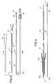
- Fig. 1
- eine erste Ausführungsform des Kathetersets nach demBraunülen-Prinzip zusammen mit einemStimulationsgerät, das bei der Verlegung desPlexuskatheters benutzt wird,
- Fig. 2
- eine vergrößerte Darstellung der Einzelheit II vonFig. 1,
- Fig. 3
- ein Katheterset nach dem Prinzip der Seldinger-Technikund
- Fig. 4
- ein Ausführungsbeispiel nach der Möllmann-Technik.
- Fig. 1
- a first embodiment of the catheter set according to the Braunulen principle together with a stimulation device which is used when laying the plexus catheter,
- Fig. 2
- 2 shows an enlarged illustration of detail II from FIG. 1,
- Fig. 3
- a catheter set based on the Seldinger technique and
- Fig. 4
- an embodiment according to the Möllmann technology.
Das Katheterset nach Fig. 1 weist einen Kurzkatheter 10 und eineStahlkanüle 11 auf, wobei der Kurzkatheter 10 über dieStahlkanüle 11 geschoben werden kann. Der Kurzkatheter 10 ist nach Art einer Braunüle ausgebildet. Er besitzt ein halbstarresRohr 12 aus Kunststoff, wobei die Katheterspitze 13kegelstumpfförmig verjüngt ist. Am distalen Ende des Rohres 12ist ein Katheteransatz 14 aus starrem Kunststoff befestigt,welcher einen (nicht dargestellten) Innenkonus und Luer-Lock-Verbindungselemente15 zum Anschließen einer Spritze oder einesSchlauchkonnektors aufweist.1 has a
Die Stahlkanüle 11 besteht aus einem Kanülenrohr 16 aus Stahl,das am distalen Ende eine asymmetrische scharfe Spitze 17aufweist. Das Kanülenrohr 16 kann mit einer isolierendenBeschichtung aus Kunststoff umhüllt sein, die nur die blankeSpitze 17 freiläßt. Am proximalen Ende des Kanülenrohrs 16befindet sich ein Kanülenansatz 19 aus Kunststoff/Metall. Ausdiesem Kanülenansatz 19 ragt ein flexibler Schlauch 20 heraus,der mit dem Lumen des Kanülenrohrs 16 in Verbindung steht undder an seinem Ende mit einem Luer-Lock-Verbinder 21 versehenist, um während der Punktion eine Flüssigkeit injizieren zukönnen. Das Kanülenrohr 16 hat eine solche Länge, daß es in denKurzkatheter 10 eingeschoben werden kann. Wenn derKatheteransatz 14 gegen den Kanülenansatz 19 stößt, ragt nurnoch die leitende Spitze 17 aus dem Katheterrohr 12 heraus.The
Das aus Stahl bestehende Kanülenrohr 16 ist mit einem Drahtverbunden, der als isoliertes Kabel 22 aus dem Kanülenansatz 19herausgeführt ist. Am Ende des Kabels 22 befindet sich eineelektrische Anschlußvorrichtung in Form eines Steckverbinders23.The
Diese Anschlußvorrichtung 23 wird an das eine Kabel 24 einesStimulationsgerätes 26 angeschlossen, welches dieStimulationsimpulse in Form elektrischer Spannungsimpulseerzeugt. Das Kabel 24 ist mit einem Steckverbinder 28 versehen,der mit dem Steckverbinder 23 zusammenpaßt. Das andere Kabel 25 des Stimulationsgerätes ist mit einer EKG-Klammer 27 verbunden,die an eine (nicht dargestellte) Hautelektrode angesetzt werdenkann, welche nahe der Punktionsstelle befestigt wird.This
Bei der Punktion ist zunächst der Steckverbinder 23 derPunktionskanüle 11 mit dem Steckverbinder 28 des Stimulationsgerätes26 verbunden. Dadurch gelangen die elektrischenStimulationsimpulse an die blanke Spitze 17 der Stahlkanüle 11.Wenn diese Spitze sich in der Nähe eines Nervenstrangesbefindet, werden die Nerven zu Reflexbewegungen angeregt.Dadurch ist für den Anästhesisten erkennbar, ob die Nähe des fürdie Nervenblockade geeigneten Bereichs erreicht wurde. Dabeiwird in der Regel die die Nerven umgebende Faszie durchstochen,ohne daß allerdings die Nerven beschädigt werden dürfen.When puncturing, the
Im Anschluß an die beschriebene Punktion wird die Stahlkanüle 11aus dem Kurzkatheter 10 herausgezogen und die Steckverbinder 23und 28 werden getrennt. Dann wird der Plexuskatheter 30 mit demdarin liegenden Stimulationsdraht 31 durch den Katheteransatz 14in den Kurzkatheter 10 eingeführt. Der Plexuskatheter 30 ist einflexibler Schlauch mit einem Außendurchmesser von etwa 1 mm. Andiesem Schlauch befinden sich Markierungen, die demAnästhesisten die Einschubtiefe anzeigen. Durch denPlexuskatheter 30 hindurch verläuft der Stimulationsdraht 31,der hinter der geschlossenen Katheterspitze endet. Am distalenEnde des Plexuskatheters 30 befindet sich eine geschlosseneKatheterspitze 32 in Form einer abgerundeten Kuppe. Das distaleEnde des Stimulationsdrahtes 31 stößt gegen die Innenwand derKatheterspitze 32. Wie aus Fig. 2 hervorgeht, besteht zwischendem Stimulationsdraht 31 und der Innenwand des Plexuskatheters30 ein Ringspalt 33. Ein Plexuskatheter 30, dessenInnendurchmesser 0,7 mm beträgt, enthält einen Stimulationsdraht31, dessen Durchmesser 0,5 mm beträgt. Der Ringspalt 33ermöglicht ein leichtes Verschieben des Stimulationsdrahtes 31 im Plexuskatheter 30. Ferner ermöglicht er auch die Injektioneines flüssigen Anästhetikums.Following the puncture described, the
In der Nähe der Katheterspitze 32 sind seitlich amPlexuskatheter 30 Löcher 34 vorgesehen, die durch die Wand desPlexuskatheters hindurchgehen. Die Löcher 34 sind umfangsmäßigäquidistant verteilt und in Längsrichtung des Plexuskathetersgegeneinander versetzt. Im vorliegenden Fall sind drei Löcher 34vorhanden, die umfangsmäßig um jeweils 120° zueinander versetztsind. Die Löcher 34 begrenzen jeweils eine Elektrode 35, die ausdem durch das Loch exponierten Teil der blanken Oberfläche desStimulationsdrahtes 31 besteht. In Fig. 2 sind die elektrischenStromlinien 36 dargestellt, die von der Elektrode 35 ausgehenund durch das Körpergewebe hindurch verlaufen. Mit 37 ist ein inder Nähe befindlicher Nerv bezeichnet, der von den Stromlinien36 erfaßt und stimuliert wird.Near the
Das proximale Ende des Stimulationsdrahtes 31, das aus demPlexus-Katheter 30 herausragt, ist mit einem Steckverbinder 38versehen, der in gleicher Weise ausgebildet ist, wie derSteckverbinder 23 und der daher mit dem Steckverbinder 28 desStimulationsgerätes 26 zusammenpaßt.The proximal end of the
Nach dem Verlegen des Kurzkatheters 10 und dem Herausziehen derStahlkanüle 11 wird der Plexuskatheter 30 mit dem darinliegendenStimulationsdraht 31 in den Kurzkatheter 10 eingeschoben. Dabeisind die Steckverbinder 28 und 38 zusammengsteckt. Unter Stimulationwird nun der Plexuskatheter 30 zusammen mit dem Stimulationsdraht31 weiter vorgeschoben, so daß unter Stimulationskontrollediejenige Stelle gefunden werden kann, an derein an der Katheterspitze 37 injiziertes Medikament die größteWirksamkeit entfaltet. Nach dem Plazieren des Plexuskatheters 30wird der Stimulationsdraht 31 herausgezogen und an das proximale Katheterende 39 wird ein Anschlußstück 40 angesetzt, welches einenLuer-Lock-Anschluß 41 zum Ankuppeln einer Spritze, die diezu injizierende Flüssigkeit enthält, aufweist.After laying the
Während bei dem ersten Ausführungsbeispiel der Plexuskatheter 30zusammen mit dem darinliegenden Stimulationsdraht 31 durch denKurzkatheter 10 hindurchgeschoben wird, ist in Fig. 3 einKatheterset dargestellt, bei dem der Plexuskatheter 30a nach derSeldinger-Methode verlegt wird. Hierzu sind ein Kurzkatheter 10und eine Stahlkanüle 11 vorgesehen, die den entsprechenden Teilendes ersten Ausführungsbeispiels entsprechen. DerStimulationsdraht 31a ist dicker als der Stimulationsdraht 31und er ist mit einem Isoliermantel 45 versehen, der nur dieStimulationselektrode 35a und den Anschlußbereich freiläßt.While in the first embodiment the
Der Plexuskatheter 30a gemäß Fig. 3 weist am proximalen Endeeinen fest angebrachten Katheteransatz 46 auf und ist amdistalen Ende offen.The
Bei Benutzung des Kathetersets nach Fig. 3 wird zunächst mit derStahlkanüle 11 und dem darauf aufgeschoben Kurzkatheter 10 diePunktion durchgeführt, wobei das Einführen unterStimulationskontrolle erfolgt. Dann wird die Stahlkanüle 11 ausdem Kurzkatheter 10 herausgezogen und der Stimulationsdraht 31awird in den Kurzkatheter 10 eingeschoben, wobei eineKontaktklemme 47 an den Anschlußbereich 48 angesteckt ist. Dasweitere Vorschieben des Stimulationsdrahtes 31a über die Spitzedes Kurzkatheters 10 heraus erfolgt also ebenfalls unterStimulationskontrolle.3 is first used with the
Wenn die Stimulationselektrode 35a die gewünschte Stelleerreicht hat, wird die Kontaktklemme 47 entfernt und vomproximalen Ende des Stimulationsdrahtes 31a her wird derStimulationskatheter 30a über den Stimulationsdraht 31a geschoben. Am Stimulationsdraht 31a befinden sich Markierungen,die anzeigen, wann die Katheterspitze 32a die Spitze desStimulationsdrahtes erreicht hat. Danach wird derStimulationsdraht 31a aus dem Plexuskatheter 30a herausgezogen.An den Katheteransatz 46 kann dann eine Spritze angeschlossenwerden.When the stimulation electrode 35a is the desired locationhas reached, the
Das Ausführungsbeispiel von Fig. 4 entspricht im wesentlichendem Katheterset von DE 44 43 672 C2. Hierbei ist eineStahlkanüle 10b vorgesehen, mit der eine Punktion vorgenommenwird, während der Plexuskatheter 30b in der Stahlkanüle 10bliegt. Der Plexuskatheter 30b enthält eine Nadel 50 mit scharferSpitze 51, die aus der Katheterspitze 32b herausragt. Dasrückwärtige Ende der Nadel 50 ist mit einem Draht 52 verbunden,der aus dem Plexuskatheter 30b herausragt. Nach dem Einführendes Plexuskatheters 30b mit Hilfe der Nadel 50 wird dieStahlkanüle 10b über den Plexuskatheter hinweg zurückgezogen.Dann wird der Plexuskatheter 30b festgehalten, während die Nadeldurch Ziehen an dem Draht 52 aus ihm herausgezogen wird.Anschließend wird ein Stimulationsdraht 31b in denPlexuskatheter 30b eingeschoben, bis die Stimulationselektrode35b am distalen Ende des Stimulationsdrahtes aus derKatheterspitze 32b hervorsteht. Dann kann der Plexuskatheter 30bzusammen mit dem Stimulationsdraht 31b weiter vorgeschobenwerden. Die Stimulationselektrode 35b bildet eine stumpfeSpitze, durch die keine Nerven beschädigt werden können. Währenddes Vorschiebens ist an den Anschlußbereich 48 eine Kontaktklemme47 angeschlossen, so daß das Vorschieben unterStimulationskontrolle durchgeführt werden kann. Wenn derPlexuskatheter 30b seine endgültige Position erreicht hat, wirdder Stimulationsdraht 31b aus ihm herausgezogen.The embodiment of FIG. 4 essentially correspondsthe catheter set from DE 44 43 672 C2. Here is oneSteel cannula 10b is provided with which a puncture is madewhile the
Claims (8)
Translated fromGermanwobei der Stimulationsdraht (31) an seinem distalen Endemindestens eine freiliegende Stimulationselektrode (35)und am proximalen Ende ein elektrisches Anschlußelement(38) aufweist.
wherein the stimulation wire (31) has at least one exposed stimulation electrode (35) at its distal end and an electrical connection element (38) at the proximal end.
Applications Claiming Priority (2)
| Application Number | Priority Date | Filing Date | Title |
|---|---|---|---|
| DE29820525U | 1998-11-17 | ||
| DE29820525UDE29820525U1 (en) | 1998-11-17 | 1998-11-17 | Catheter set for plexus anesthesia |
Publications (1)
| Publication Number | Publication Date |
|---|---|
| EP1002500A1true EP1002500A1 (en) | 2000-05-24 |
Family
ID=8065437
Family Applications (1)
| Application Number | Title | Priority Date | Filing Date |
|---|---|---|---|
| EP99120710AWithdrawnEP1002500A1 (en) | 1998-11-17 | 1999-10-19 | Catheter set for plexus anaesthesia |
Country Status (3)
| Country | Link |
|---|---|
| EP (1) | EP1002500A1 (en) |
| JP (1) | JP2000140132A (en) |
| DE (1) | DE29820525U1 (en) |
Cited By (30)
| Publication number | Priority date | Publication date | Assignee | Title |
|---|---|---|---|---|
| WO2002055145A1 (en)* | 2001-01-11 | 2002-07-18 | Heinrich Pajunk | Catheter for neural blockades |
| EP1574231A1 (en)* | 2004-03-10 | 2005-09-14 | Brushey Stephen | Anesthesia conduction catheter for delivery of electrical stimulus |
| US6986789B2 (en) | 2003-08-22 | 2006-01-17 | Aesculap Ag & Co. Kg | Intervertebral implant |
| US7198644B2 (en) | 2003-07-08 | 2007-04-03 | Aesculap Ag & Co. Kg | Intervertebral implant |
| US7549995B2 (en) | 2003-07-08 | 2009-06-23 | Aesculap Ag | Surgical instrument for handling an implant |
| US7585325B2 (en) | 2004-06-16 | 2009-09-08 | Aesculap Ag | Intervertebral implant |
| US7655045B2 (en) | 2003-05-06 | 2010-02-02 | Aesculap Implant Systems, Llc | Artificial intervertebral disc |
| US7832409B2 (en) | 2003-05-06 | 2010-11-16 | Aesculap Implant Systems, Llc | Method of inserting an artificial intervertebral disc |
| US8185205B2 (en) | 2007-10-22 | 2012-05-22 | B. Braun Medical Inc. | Catheter switch and method of using a catheter switch in administering a nerve or plexus block |
| US20130158427A1 (en)* | 2010-09-10 | 2013-06-20 | Sewoon Medical Co., Ltd. | Catheter set comprising guide wire |
| US8628469B2 (en) | 2003-09-25 | 2014-01-14 | Nuvasive, Inc. | Surgical access system and related methods |
| US8663100B2 (en) | 2002-10-08 | 2014-03-04 | Nuvasive, Inc. | Surgical access system and related methods |
| US8672840B2 (en) | 2002-06-26 | 2014-03-18 | Nuvasive, Inc. | Surgical access system and related methods |
| US8696559B2 (en) | 2003-02-27 | 2014-04-15 | Nuvasive, Inc. | Surgical access system and related methods |
| US8738123B2 (en) | 2001-09-25 | 2014-05-27 | Nuvasive, Inc. | System and methods for performing surgical procedures and assessments |
| US8747307B2 (en) | 2003-01-16 | 2014-06-10 | Nuvasive, Inc. | Surgical access system and related methods |
| US8790406B1 (en) | 2011-04-01 | 2014-07-29 | William D. Smith | Systems and methods for performing spine surgery |
| US8812116B2 (en) | 2001-07-11 | 2014-08-19 | Nuvasive, Inc. | System and methods for determining nerve proximity, direction, and pathology during surgery |
| WO2014124719A1 (en) | 2013-02-15 | 2014-08-21 | Pajunk GmbH Medizintechnologie | Set for peripheral nerve blocking |
| US9198765B1 (en) | 2011-10-31 | 2015-12-01 | Nuvasive, Inc. | Expandable spinal fusion implants and related methods |
| US9314152B2 (en) | 2003-09-25 | 2016-04-19 | Nuvasive, Inc. | Surgical access system and related methods |
| US9532796B2 (en) | 2010-06-30 | 2017-01-03 | Myromed, Llc | Devices and methods for cutting tissue |
| US9622732B2 (en) | 2004-10-08 | 2017-04-18 | Nuvasive, Inc. | Surgical access system and related methods |
| US9743853B2 (en) | 1999-11-24 | 2017-08-29 | Nuvasive, Inc. | Electromyography system |
| US9763731B2 (en) | 2012-02-10 | 2017-09-19 | Myromed, Llc | Vacuum powered rotary devices and methods |
| DE102016110379A1 (en) | 2016-06-06 | 2017-12-07 | Pajunk GmbH Medizintechnologie | Unipolar cannula |
| US9937317B2 (en) | 2012-01-30 | 2018-04-10 | Ipsumpro, S.L. | Modified medical syringe with a flow regulator for the administration of local anaesthetic |
| EP3620208A1 (en) | 2018-09-06 | 2020-03-11 | Pajunk GmbH Medizintechnologie | Cannula |
| US10959860B2 (en) | 2008-12-26 | 2021-03-30 | Pantheon Spinal, Llc | Method of retroperitoneal lateral insertion of spinal implants |
| EP4292635A3 (en)* | 2022-05-23 | 2024-02-21 | B. Braun Melsungen AG | Catheter set for forming different catheter assemblies for peripheral regional anesthesia |
Families Citing this family (6)
| Publication number | Priority date | Publication date | Assignee | Title |
|---|---|---|---|---|
| DE20107778U1 (en) | 2001-05-08 | 2001-10-11 | B. Braun Melsungen Ag, 34212 Melsungen | Puncture cannula |
| KR101185944B1 (en)* | 2009-03-13 | 2012-09-25 | 최상식 | Catheter set having guide wire |
| KR102384707B1 (en)* | 2020-05-20 | 2022-04-08 | 인제대학교 산학협력단 | Tunneling apparatus for nerve block |
| KR102633526B1 (en)* | 2020-11-17 | 2024-02-06 | 가톨릭관동대학교산학협력단 | Catheter apparatus capable of signal correction according to length |
| DE102023123897A1 (en)* | 2023-09-05 | 2025-03-06 | Pajunk GmbH Medizintechnologie | nerve stimulation set |
| DE102023123896A1 (en)* | 2023-09-05 | 2025-03-06 | Pajunk GmbH Medizintechnologie | device for nerve stimulation |
Citations (4)
| Publication number | Priority date | Publication date | Assignee | Title |
|---|---|---|---|---|
| DE3229466A1 (en) | 1982-08-06 | 1984-02-09 | Sterimed Gesellschaft für medizinischen Bedarf mbH, 6600 Saarbrücken | POINTING AND CATHETERIZING DEVICE FOR HUMAN OR ANIMAL BODIES |
| DE8803153U1 (en)* | 1988-03-09 | 1988-06-23 | B. Braun Melsungen Ag, 3508 Melsungen | Catheter device for plexus anesthesia |
| DE4443672A1 (en) | 1994-04-25 | 1995-10-26 | Braun Melsungen Ag | Device for inserting a catheter into a body cavity |
| WO1998033547A1 (en)* | 1997-01-30 | 1998-08-06 | Mayo Foundation For Medical Education And Research | Peripheral nerve site anesthesia |
Family Cites Families (7)
| Publication number | Priority date | Publication date | Assignee | Title |
|---|---|---|---|---|
| DE8106577U1 (en)* | 1981-03-07 | 1981-08-13 | Zenz, Michael, Dr., 3000 Hannover | INJECTION DEVICE FOR BLOCKING PERIPHERAL NERVES, e.g. ON PLEXUSANESTHESIA |
| DE8222222U1 (en)* | 1982-08-06 | 1982-11-25 | Mehler, Doron, Dr., 3000 Hannover | CATHETER SET |
| DE3508013A1 (en)* | 1984-07-28 | 1986-02-06 | Peter 7730 Villingen-Schwenningen Krebs | COMBINATION NEEDLE FOR THE AXILLAERE PLEXUS-BRACHIALIS-ANESTHESIA |
| DE8510201U1 (en)* | 1985-04-04 | 1985-05-30 | Mehler, Doron, Dr., 3000 Hannover | Catheter set |
| DE8629969U1 (en)* | 1986-11-08 | 1987-01-02 | Dotterweich, Hans, 79268 Bötzingen | Cannula for regional anesthesia |
| DE8712603U1 (en)* | 1987-09-18 | 1987-11-05 | B. Braun Melsungen Ag, 34212 Melsungen | Plexus cannula for plexus anesthesia |
| DE8715740U1 (en)* | 1987-11-27 | 1988-01-14 | Krebs, Peter, Dr., 7730 Villingen-Schwenningen | Combination needle for axillary plexus brachialis anesthesia |
- 1998
- 1998-11-17DEDE29820525Upatent/DE29820525U1/ennot_activeExpired - Lifetime
- 1999
- 1999-10-04JPJP28262899Apatent/JP2000140132A/enactivePending
- 1999-10-19EPEP99120710Apatent/EP1002500A1/ennot_activeWithdrawn
Patent Citations (4)
| Publication number | Priority date | Publication date | Assignee | Title |
|---|---|---|---|---|
| DE3229466A1 (en) | 1982-08-06 | 1984-02-09 | Sterimed Gesellschaft für medizinischen Bedarf mbH, 6600 Saarbrücken | POINTING AND CATHETERIZING DEVICE FOR HUMAN OR ANIMAL BODIES |
| DE8803153U1 (en)* | 1988-03-09 | 1988-06-23 | B. Braun Melsungen Ag, 3508 Melsungen | Catheter device for plexus anesthesia |
| DE4443672A1 (en) | 1994-04-25 | 1995-10-26 | Braun Melsungen Ag | Device for inserting a catheter into a body cavity |
| WO1998033547A1 (en)* | 1997-01-30 | 1998-08-06 | Mayo Foundation For Medical Education And Research | Peripheral nerve site anesthesia |
Cited By (84)
| Publication number | Priority date | Publication date | Assignee | Title |
|---|---|---|---|---|
| US9743853B2 (en) | 1999-11-24 | 2017-08-29 | Nuvasive, Inc. | Electromyography system |
| US7805188B2 (en) | 2000-03-24 | 2010-09-28 | Micor, Inc. | Anesthesia conduction catheter for delivery of electrical stimulus |
| WO2002055145A1 (en)* | 2001-01-11 | 2002-07-18 | Heinrich Pajunk | Catheter for neural blockades |
| US9456783B2 (en) | 2001-07-11 | 2016-10-04 | Nuvasive, Inc. | System and methods for determining nerve proximity, direction and pathology during surgery |
| US9037250B2 (en) | 2001-07-11 | 2015-05-19 | Nuvasive, Inc. | System and methods for determining nerve proximity, direction and pathology during surgery |
| US9931077B2 (en) | 2001-07-11 | 2018-04-03 | Nuvasive, Inc. | System and methods for determining nerve proximity, direction and pathology during surgery |
| US8812116B2 (en) | 2001-07-11 | 2014-08-19 | Nuvasive, Inc. | System and methods for determining nerve proximity, direction, and pathology during surgery |
| US10716509B2 (en) | 2001-07-11 | 2020-07-21 | Nuvasive, Inc. | System and methods for determining nerve proximity, direction and pathology during surgery |
| US10507120B2 (en) | 2001-09-25 | 2019-12-17 | Nuvasive, Inc. | Systems and methods for performing surgical procedures and assessments |
| US8977352B2 (en) | 2001-09-25 | 2015-03-10 | Nuvasive, Inc. | Systems and methods for performing surgical procedures and assessments |
| US8768450B2 (en) | 2001-09-25 | 2014-07-01 | Nuvasive, Inc. | System and methods for performing surgical procedures and assessments |
| US8738123B2 (en) | 2001-09-25 | 2014-05-27 | Nuvasive, Inc. | System and methods for performing surgical procedures and assessments |
| US9826968B2 (en) | 2002-06-26 | 2017-11-28 | Nuvasive, Inc. | Surgical access system and related methods |
| US10251633B2 (en) | 2002-06-26 | 2019-04-09 | Nuvasive, Inc. | Surgical access system and related methods |
| US8672840B2 (en) | 2002-06-26 | 2014-03-18 | Nuvasive, Inc. | Surgical access system and related methods |
| US9750490B2 (en) | 2002-06-26 | 2017-09-05 | Nuvasive, Inc. | Surgical access system and related methods |
| US9833227B2 (en) | 2002-06-26 | 2017-12-05 | Nuvasive, Inc. | Surgical access system and related methods |
| US8708899B2 (en) | 2002-06-26 | 2014-04-29 | Nuvasive, Inc. | Surgical access system and related methods |
| US8915846B2 (en) | 2002-06-26 | 2014-12-23 | Nuvasive, Inc. | Surgical access system and related methods |
| US9848861B2 (en) | 2002-06-26 | 2017-12-26 | Nuvasive, Inc. | Surgical access system and related methods |
| US10980524B2 (en) | 2002-06-26 | 2021-04-20 | Nuvasive, Inc. | Surgical access system and related methods |
| US9820729B2 (en) | 2002-10-08 | 2017-11-21 | Nuvasive, Inc. | Surgical access system and related methods |
| US10695044B2 (en) | 2002-10-08 | 2020-06-30 | Nuvasive, Inc. | Surgical access system and related methods |
| US8679006B2 (en) | 2002-10-08 | 2014-03-25 | Nuvasive, Inc. | Surgical access system and related methods |
| US9204871B2 (en) | 2002-10-08 | 2015-12-08 | Nuvasive, Inc. | Surgical access system and related methods |
| US8663100B2 (en) | 2002-10-08 | 2014-03-04 | Nuvasive, Inc. | Surgical access system and related methods |
| US8956283B2 (en) | 2002-10-08 | 2015-02-17 | Nuvasive, Inc. | Surgical access system and related methods |
| US9572562B2 (en) | 2002-10-08 | 2017-02-21 | Nuvasive, Inc. | Surgical access system and related methods |
| US8747307B2 (en) | 2003-01-16 | 2014-06-10 | Nuvasive, Inc. | Surgical access system and related methods |
| US9795371B2 (en) | 2003-01-16 | 2017-10-24 | Nuvasive, Inc. | Surgical access system and related methods |
| US8753270B2 (en) | 2003-01-16 | 2014-06-17 | Nuvasive, Inc. | Surgical access system and related methods |
| US10357238B2 (en) | 2003-01-16 | 2019-07-23 | Nuvasive, Inc. | Surgical access system and related methods |
| US11219440B2 (en) | 2003-01-16 | 2022-01-11 | Nuvasive, Inc. | Surgical access system and related methods |
| US9301743B2 (en) | 2003-01-16 | 2016-04-05 | Nuvasive, Inc. | Surgical access system and related methods |
| US9468405B2 (en) | 2003-02-27 | 2016-10-18 | Nuvasive, Inc. | Surgical access system and related methods |
| US8696559B2 (en) | 2003-02-27 | 2014-04-15 | Nuvasive, Inc. | Surgical access system and related methods |
| US7766966B2 (en) | 2003-05-06 | 2010-08-03 | Aesculap Implant Systems, Llc | Artificial intervertebral disc |
| US7832409B2 (en) | 2003-05-06 | 2010-11-16 | Aesculap Implant Systems, Llc | Method of inserting an artificial intervertebral disc |
| US7655045B2 (en) | 2003-05-06 | 2010-02-02 | Aesculap Implant Systems, Llc | Artificial intervertebral disc |
| US7198644B2 (en) | 2003-07-08 | 2007-04-03 | Aesculap Ag & Co. Kg | Intervertebral implant |
| US7549995B2 (en) | 2003-07-08 | 2009-06-23 | Aesculap Ag | Surgical instrument for handling an implant |
| US6986789B2 (en) | 2003-08-22 | 2006-01-17 | Aesculap Ag & Co. Kg | Intervertebral implant |
| US9974531B2 (en) | 2003-09-25 | 2018-05-22 | Nuvasive, Inc. | Surgical access system and related methods |
| US8945004B2 (en) | 2003-09-25 | 2015-02-03 | Nuvasive, Inc. | Surgical access system and related methods |
| US10357233B2 (en) | 2003-09-25 | 2019-07-23 | Nuvasive, Inc. | Surgical access system and related methods |
| US9610071B2 (en) | 2003-09-25 | 2017-04-04 | Nuvasive, Inc. | Surgical access system and related methods |
| US11064934B2 (en) | 2003-09-25 | 2021-07-20 | Nuvasive, Inc. | Surgical access system and related methods |
| US8821396B1 (en) | 2003-09-25 | 2014-09-02 | Nuvasive, Inc. | Surgical access system and related methods |
| US9314152B2 (en) | 2003-09-25 | 2016-04-19 | Nuvasive, Inc. | Surgical access system and related methods |
| US9265493B2 (en) | 2003-09-25 | 2016-02-23 | Nuvasive, Inc. | Surgical access system and related methods |
| US8753271B1 (en) | 2003-09-25 | 2014-06-17 | Nuvasive, Inc. | Surgical access system and related methods |
| US8764649B2 (en) | 2003-09-25 | 2014-07-01 | Nuvasive, Inc. | Surgical access system and related methods |
| US9788822B2 (en) | 2003-09-25 | 2017-10-17 | Nuvasive, Inc. | Surgical access system and related methods |
| US8942801B2 (en) | 2003-09-25 | 2015-01-27 | Nuvasive, Inc. | Surgical access system and related methods |
| US8628469B2 (en) | 2003-09-25 | 2014-01-14 | Nuvasive, Inc. | Surgical access system and related methods |
| US10653308B2 (en) | 2003-10-17 | 2020-05-19 | Nuvasive, Inc. | Surgical access system and related methods |
| EP1574231A1 (en)* | 2004-03-10 | 2005-09-14 | Brushey Stephen | Anesthesia conduction catheter for delivery of electrical stimulus |
| US7585325B2 (en) | 2004-06-16 | 2009-09-08 | Aesculap Ag | Intervertebral implant |
| US11723644B2 (en) | 2004-10-08 | 2023-08-15 | Nuvasive, Inc. | Surgical access system and related methods |
| US9622732B2 (en) | 2004-10-08 | 2017-04-18 | Nuvasive, Inc. | Surgical access system and related methods |
| US8185205B2 (en) | 2007-10-22 | 2012-05-22 | B. Braun Medical Inc. | Catheter switch and method of using a catheter switch in administering a nerve or plexus block |
| US11969359B2 (en) | 2008-12-26 | 2024-04-30 | Pantheon Spinal, Llc | Method of retroperitoneal lateral insertion of spinal implants |
| US10959860B2 (en) | 2008-12-26 | 2021-03-30 | Pantheon Spinal, Llc | Method of retroperitoneal lateral insertion of spinal implants |
| US12383411B2 (en) | 2008-12-26 | 2025-08-12 | Pantheon Spinal, Llc | Spinal surgery methods and devices |
| US9532796B2 (en) | 2010-06-30 | 2017-01-03 | Myromed, Llc | Devices and methods for cutting tissue |
| US9216269B2 (en)* | 2010-09-10 | 2015-12-22 | Sewoon Medical Co., Ltd. | Catheter set comprising guide wire |
| US9504803B2 (en) | 2010-09-10 | 2016-11-29 | Sewoon Medical Co., Ltd. | Catheter set comprising guide wire |
| US20130158427A1 (en)* | 2010-09-10 | 2013-06-20 | Sewoon Medical Co., Ltd. | Catheter set comprising guide wire |
| US9949840B1 (en) | 2011-04-01 | 2018-04-24 | William D. Smith | Systems and methods for performing spine surgery |
| US8790406B1 (en) | 2011-04-01 | 2014-07-29 | William D. Smith | Systems and methods for performing spine surgery |
| US9198765B1 (en) | 2011-10-31 | 2015-12-01 | Nuvasive, Inc. | Expandable spinal fusion implants and related methods |
| US9655744B1 (en) | 2011-10-31 | 2017-05-23 | Nuvasive, Inc. | Expandable spinal fusion implants and related methods |
| US9937317B2 (en) | 2012-01-30 | 2018-04-10 | Ipsumpro, S.L. | Modified medical syringe with a flow regulator for the administration of local anaesthetic |
| US9763731B2 (en) | 2012-02-10 | 2017-09-19 | Myromed, Llc | Vacuum powered rotary devices and methods |
| US9770289B2 (en) | 2012-02-10 | 2017-09-26 | Myromed, Llc | Vacuum powered rotary devices and methods |
| DE102013101538C5 (en) | 2013-02-15 | 2019-03-28 | Pajunk GmbH Medizintechnologie | Set for the peripheral nerve block |
| US11167114B2 (en) | 2013-02-15 | 2021-11-09 | Pajunk GmbH Medizintechnologie | Set for peripheral nerve blocking |
| EP2956071B1 (en)* | 2013-02-15 | 2021-04-07 | Pajunk GmbH Medizintechnologie | Set for peripheral nerve blocking |
| WO2014124719A1 (en) | 2013-02-15 | 2014-08-21 | Pajunk GmbH Medizintechnologie | Set for peripheral nerve blocking |
| US11191564B2 (en) | 2016-06-06 | 2021-12-07 | Pajunk GmbH Medizintechnologie | Unipolar cannula |
| DE102016110379A1 (en) | 2016-06-06 | 2017-12-07 | Pajunk GmbH Medizintechnologie | Unipolar cannula |
| US11534202B2 (en) | 2018-09-06 | 2022-12-27 | Pajunk GmbH Medizintechnologie | Cannula |
| EP3620208A1 (en) | 2018-09-06 | 2020-03-11 | Pajunk GmbH Medizintechnologie | Cannula |
| EP4292635A3 (en)* | 2022-05-23 | 2024-02-21 | B. Braun Melsungen AG | Catheter set for forming different catheter assemblies for peripheral regional anesthesia |
Also Published As
| Publication number | Publication date |
|---|---|
| JP2000140132A (en) | 2000-05-23 |
| DE29820525U1 (en) | 2000-04-06 |
Similar Documents
| Publication | Publication Date | Title |
|---|---|---|
| EP1002500A1 (en) | Catheter set for plexus anaesthesia | |
| DE3327585C2 (en) | ||
| DE8803153U1 (en) | Catheter device for plexus anesthesia | |
| EP2956071B1 (en) | Set for peripheral nerve blocking | |
| EP1260186B1 (en) | Needle assembly for blocking peripheral nerves | |
| EP1267980B1 (en) | Catheter for neural blockades | |
| EP0102538A1 (en) | Device for puncture and catheterisation for human or animal bodies | |
| DE202008018476U1 (en) | A deployment system and guide for treating a target tissue region | |
| EP1849493A1 (en) | Catheter set for epidural or peripheral nerve block | |
| DE2929233A1 (en) | DEVICE FOR FORMING A TISSUE TUNNEL AND / OR FOR POSITIONING A PIPE IN BODY TISSUE | |
| WO1997015347A1 (en) | Stimulation device | |
| DE19640670B4 (en) | Bipolar electrode | |
| DE102017111280B4 (en) | Electro-medical adapter, electromedical electrode and electromedical pulse generator | |
| DE19807487C2 (en) | Use of a catheter for nerve block | |
| EP0966922B2 (en) | Unipolar cannula for continuous anaesthesia | |
| DE102016112598A1 (en) | Catheter set for vascular access | |
| DE3526738C2 (en) | ||
| AT406121B (en) | Anaesthesiology needle | |
| DE8715740U1 (en) | Combination needle for axillary plexus brachialis anesthesia | |
| EP4520390A1 (en) | Set for nerve stimulation | |
| DE102023130417A1 (en) | Medical order for electrical neurostimulation | |
| DE102023123896A1 (en) | device for nerve stimulation | |
| EP2181656A1 (en) | Device for inserting medical implants | |
| DE8229899U1 (en) | ELECTRICALLY CONDUCTIVE CONNECTOR FOR DEVICES FOR CONTROLLING THE POSITION OF CENTRAL VENETON CATHETERS | |
| DE2516712A1 (en) | Catheter electrode for implantable electrode - has lead end finishing in curved hook pivoted out of flat section |
Legal Events
| Date | Code | Title | Description |
|---|---|---|---|
| PUAI | Public reference made under article 153(3) epc to a published international application that has entered the european phase | Free format text:ORIGINAL CODE: 0009012 | |
| AK | Designated contracting states | Kind code of ref document:A1 Designated state(s):AT BE CH CY DE DK ES FI FR GB GR IE IT LI LU MC NL PT SE | |
| AX | Request for extension of the european patent | Free format text:AL;LT;LV;MK;RO;SI | |
| 17P | Request for examination filed | Effective date:20000707 | |
| AKX | Designation fees paid | Free format text:AT BE CH CY DE DK ES FI FR GB GR IE IT LI LU MC NL PT SE | |
| 17Q | First examination report despatched | Effective date:20030929 | |
| STAA | Information on the status of an ep patent application or granted ep patent | Free format text:STATUS: THE APPLICATION IS DEEMED TO BE WITHDRAWN | |
| 18D | Application deemed to be withdrawn | Effective date:20050311 |