EP1002450B1 - Method for operating a direct current metal halogen arc lamp and circuit pertaining thereto - Google Patents
Method for operating a direct current metal halogen arc lamp and circuit pertaining theretoDownload PDFInfo
- Publication number
- EP1002450B1 EP1002450B1EP98944998AEP98944998AEP1002450B1EP 1002450 B1EP1002450 B1EP 1002450B1EP 98944998 AEP98944998 AEP 98944998AEP 98944998 AEP98944998 AEP 98944998AEP 1002450 B1EP1002450 B1EP 1002450B1
- Authority
- EP
- European Patent Office
- Prior art keywords
- period
- aus
- ein
- region
- arc lamp
- Prior art date
- Legal status (The legal status is an assumption and is not a legal conclusion. Google has not performed a legal analysis and makes no representation as to the accuracy of the status listed.)
- Expired - Lifetime
Links
Images


Classifications
- H—ELECTRICITY
- H05—ELECTRIC TECHNIQUES NOT OTHERWISE PROVIDED FOR
- H05B—ELECTRIC HEATING; ELECTRIC LIGHT SOURCES NOT OTHERWISE PROVIDED FOR; CIRCUIT ARRANGEMENTS FOR ELECTRIC LIGHT SOURCES, IN GENERAL
- H05B41/00—Circuit arrangements or apparatus for igniting or operating discharge lamps
- H05B41/14—Circuit arrangements
- H05B41/36—Controlling
- H05B41/38—Controlling the intensity of light
- H05B41/39—Controlling the intensity of light continuously
- H05B41/392—Controlling the intensity of light continuously using semiconductor devices, e.g. thyristor
- H—ELECTRICITY
- H05—ELECTRIC TECHNIQUES NOT OTHERWISE PROVIDED FOR
- H05B—ELECTRIC HEATING; ELECTRIC LIGHT SOURCES NOT OTHERWISE PROVIDED FOR; CIRCUIT ARRANGEMENTS FOR ELECTRIC LIGHT SOURCES, IN GENERAL
- H05B41/00—Circuit arrangements or apparatus for igniting or operating discharge lamps
- H05B41/14—Circuit arrangements
- H05B41/26—Circuit arrangements in which the lamp is fed by power derived from DC by means of a converter, e.g. by high-voltage DC
- H05B41/28—Circuit arrangements in which the lamp is fed by power derived from DC by means of a converter, e.g. by high-voltage DC using static converters
- H05B41/288—Circuit arrangements in which the lamp is fed by power derived from DC by means of a converter, e.g. by high-voltage DC using static converters with semiconductor devices and specially adapted for lamps without preheating electrodes, e.g. for high-intensity discharge lamps, high-pressure mercury or sodium lamps or low-pressure sodium lamps
- H05B41/2881—Load circuits; Control thereof
- H05B41/2882—Load circuits; Control thereof the control resulting from an action on the static converter
- H—ELECTRICITY
- H05—ELECTRIC TECHNIQUES NOT OTHERWISE PROVIDED FOR
- H05B—ELECTRIC HEATING; ELECTRIC LIGHT SOURCES NOT OTHERWISE PROVIDED FOR; CIRCUIT ARRANGEMENTS FOR ELECTRIC LIGHT SOURCES, IN GENERAL
- H05B41/00—Circuit arrangements or apparatus for igniting or operating discharge lamps
- H05B41/14—Circuit arrangements
- H05B41/36—Controlling
- H05B41/38—Controlling the intensity of light
- H05B41/39—Controlling the intensity of light continuously
- H05B41/392—Controlling the intensity of light continuously using semiconductor devices, e.g. thyristor
- H05B41/3921—Controlling the intensity of light continuously using semiconductor devices, e.g. thyristor with possibility of light intensity variations
- H05B41/3927—Controlling the intensity of light continuously using semiconductor devices, e.g. thyristor with possibility of light intensity variations by pulse width modulation
- H05B41/3928—Controlling the intensity of light continuously using semiconductor devices, e.g. thyristor with possibility of light intensity variations by pulse width modulation for high-pressure lamps, e.g. high-intensity discharge lamps, high-pressure mercury or sodium lamps
- Y—GENERAL TAGGING OF NEW TECHNOLOGICAL DEVELOPMENTS; GENERAL TAGGING OF CROSS-SECTIONAL TECHNOLOGIES SPANNING OVER SEVERAL SECTIONS OF THE IPC; TECHNICAL SUBJECTS COVERED BY FORMER USPC CROSS-REFERENCE ART COLLECTIONS [XRACs] AND DIGESTS
- Y02—TECHNOLOGIES OR APPLICATIONS FOR MITIGATION OR ADAPTATION AGAINST CLIMATE CHANGE
- Y02B—CLIMATE CHANGE MITIGATION TECHNOLOGIES RELATED TO BUILDINGS, e.g. HOUSING, HOUSE APPLIANCES OR RELATED END-USER APPLICATIONS
- Y02B20/00—Energy efficient lighting technologies, e.g. halogen lamps or gas discharge lamps
Definitions
- the present inventionrelates to a method for operating a direct current metal halide arc lamp according to claim 1, an associated circuit arrangement according to claim 10 and a method for operating a Rectangular AC metal halide arc lamp according to claim 17.
- DC metal halide arc lampsare used, for example, for projection applications needed.
- the spectrumshould sufficient in the place of the highest luminance, in front of the cathode Portions of the primary colors blue, green and red included.
- the filling elementsUse indium for blue and lithium for red.
- the proportion of red in the Lightmay be increased, however, it should be borne in mind that lithium predominantly shows very long-wave emissions, i.e. to a very deep red Share leads.
- DE-A-2 705 540discloses a method for operating a low pressure fluorescent lamp in tubular form and a circuit arrangement for Operating such a low-pressure fluorescent lamp according to this method.
- Ais applied to the electrodes of the low-pressure fluorescent lamp preload superimposed with voltage pulses.
- the bias voltage 800 Vthe maximum pulse voltage 10000 V and the Pulse duration between 0.1 ⁇ s and 10 ⁇ s.
- This documentalso discloses that with pulse repetition frequencies in the order of 60 Hz to 20,000 Hz the pulse duration generally in the range of about 0.1 to 10% of the pulse train period lies.
- US-A-4 904 903discloses a method of operating a rectangular AC metal halide arc lamp with alternating positive and negative pulse trains. There is between each pulse train inserted a currentless break. For the period between the pulses a value of 1 ms can be taken from this font within a train become.
- DE-A-3 636 901discloses a method for operating a rectangular alternating current sodium vapor discharge lamp with alternating positive and negative pulse trains. There is between each pulse train inserted a break. The frequency of the pulses within each pulse train is e.g. between 20 and 50 kHz.
- the objectis characterized by the features of the independent Claims resolved.
- the basic idea of the inventionis to operate the DC metal halide arc lamp with a clocked voltage signal.
- the signalis cyclically cycled to an on-amplitude during a period T on and to a voltage of a smaller amplitude during the subsequent period T off .
- the time period Tis one between 10 and 100 microseconds and the period T of between 1 and 50 microseconds. The same applies to the operation of rectangular AC lamps according to the invention.
- the inventionoffers the advantage of significantly increasing the radiation of the element lithium or other elements of group 1A, ie the red component, in front of the cathode. Since the normal calibration curve x ⁇ has its maximum in this spectral region, the standard color value x increases compared to y. Therefore, by adding an element with radiation lines in the range 520 to 580 nm, for example thallium 535.1 nm, the y value can be increased without the Planck curve being exceeded and the color impression shifting to green. With an increase in the y value, there is an increase in the useful luminous flux.
- the circuit arrangement according to the inventionit has proven to be particularly advantageous to choose the operation of the pulsator in such a way that the voltage in the output signal of the pulsator is essentially 0 V during the time T out .
- the time period Ta vary periodically or T ', for example, be swept with a sweep frequency of 50 to 500 Hz, preferably 100 Hz.
- the time period T off or T ' offcan be constant or can also be varied.
- T from respectively T 'froma variation occurs in a particularly advantageous manner in adaptation to the variation of T a and T' into consideration, with the aim that the generated in the signal after the ignition device for the control of the square wave AC lamp minimum voltage value despite of variation of T a and T a magnitude remains constant '. Further advantageous embodiments are described in the subclaims.
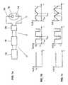
- FIG. 1ashows a block diagram of a circuit arrangement for operation a DC metal halide arc lamp 10 having an anode 12 and includes a cathode 14.
- This circuit arrangementcomprises an electrical one Ballast 16, a pulsator 18 and an igniter 20.
- FIG. 1bthe time course of the output voltage after the electrical ballast 16 is shown on the left. As can be seen, this is a signal with constant voltage U v .
- the course of the voltage U p (t) after the pulsator 18is shown in the middle of FIG. 1b.
- Tis the tension of the amplitude U p
- nis smaller than U p
- U npreferably being essentially 0 V.
- the right diagram of FIG. 1bshows the voltage curve after the igniter 20, ie the curve of the voltage U L (t) applied to the lamp.
- the signal U L (t) which operates the lampcan also be generated separately, ie without the influence of the igniter, for example by means of a suitably keyed square-wave signal or by adding a DC voltage signal to a sawtooth signal. It is then applied to the lamp in addition to an ignition circuit which ensures the ignition of the lamp and is then no longer used.
- the three diagrams in FIG. 1cshow from the left the time profile of the current I v (t) after the electrical ballast 16, the time profile of the current I p (t) after the pulsator 18 and the time profile of the current I L (t ) after the ignitor 20, ie the current flowing through the lamp.
- the time period Tis a time duration T and the off during operation of the lamp constant.
- the constant DC voltageis chopped by the pulsator after it has been ignited and after a certain start-up time, ie until a predetermined lamp voltage is exceeded.
- FIG. 2schematically shows the course of the voltage U L (t) over time for a second exemplary embodiment.
- the circuit arrangementis supplemented in accordance with Figure 1a to a device which enables the period of time T a ein_min between a minimum value T and to vary a maximum value T ein_max, ie for example ein_min between T and effetzusweepen T ein_max having a frequency F continuously.
- the curve marked Ashows the curve of the voltage U L (t) at the beginning of a sweep period
- the curve marked Bshows the curve of the voltage U L (t) at the end of a period of the sweep frequency F.
- the sweep frequency Fis typically between 50 and 500 Hz, preferably 100 Hz. This mode of operation prevents acoustic resonances.
- Tmay be a constant, while T is varied from a sweep frequency F between T and T aus_min aus_max, while in another embodiment, both T a T be varied from a sweep frequency F as well.
- the ratio of T a and Tcan be adjusted in each case so that the resulting minimum value U L min during the entire operation is constant.
- the reflector spectrumis represented by a 6 mm aperture for two differently operated and filled DC metal halide arc lamps.
- the standard color value xincreases compared to y. Therefore, by adding an element with radiation lines in the range 510 to 580 nm, in the present case thallium 535.1 nm, the y value can be increased without the Planck curve being exceeded and the color impression shifting to green. The increase in the luminous flux results from the increase in the y value.
- the useful luminous fluxincreases by approx. 5 to 10%.
- the concentration of lithiumwhich is preferably in the form of lithium iodide or bromide is added is 0.2 ⁇ mol / ml to 5 ⁇ mol / ml.
- the concentration of thalliumwhich is preferably in the form of Thallium iodide or bromide can be added up to a value of 3 ⁇ mol / ml, preferably between 0.6 ⁇ mol / ml and 3 ⁇ mol / ml.
- FIG. 4ashows a circuit arrangement for operating a rectangular AC lamp.
- a ballast 116is followed by a pulsator 118 Ignitor 120 connects.
- the rectangular ac lampis 110 denotes and comprises two identical electrodes 112, 114.
- FIG. 4bshows as an output of the ballast 116 is a rectangular alternating signal during a time period T P a voltage amplitude of U + v, and has a period T N a voltage amplitude of -U v.
- the signal after the pulsator 118is characterized in that the voltage is chopped both during the period T P and during the period T N.
- the signal after the ignition device 120ie the signal that is present at the lamp, is characterized by a sawtooth-like course both in the positive voltage range and in the negative voltage range.
- a chopped AC rectangular signalsimilar to the view in Fig. 4b center, respectively, are used, the place of the rectangles of the durations T a, T off, T has 'a and T' of a triangular shape a signal. It is essential that the time periods T off or T ' off , ie the time periods of lower amplitude or the decrease from an - possibly local - maximum to an - optionally local - minimum in the range of positive voltage and accordingly in the range of negative voltage in the range between 1 and 50 ⁇ s are.
- the signal which controls the lamp during operationcan be generated separately and can only be supplied after the lamp has been ignited.
- U L (t)can be generated, for example, by adding a square-wave change signal and a sawtooth signal.
- the time periods T a and T 'is apreferably lie between 10 and 100 microseconds.
- T Tcan in the method of operating a DC metal halide arc lamp also here, 'a, T from respectively T' made independently be constant or be varied with time.
- the sum of T P and T Nresults in a frequency F R of the order of 50 to 600 Hz.
- the sub-time durations T a, T 'a, T from respectively T' madecan be tuned the temporal variation to the frequency F R be, preferably such that a complete period of the sweep frequency F can run during the time period T P or T N.
- the sweep frequency Fis between 50 and 1500 Hz.
- a further embodimentprovides that only the voltage during the period T P or only the voltage during the period T N is chopped and the other voltage is left unhacked.
Landscapes
- Circuit Arrangements For Discharge Lamps (AREA)
- Discharge Lamp (AREA)
Description
Translated fromGermanDie vorliegende Erfindung betrifft ein Verfahren zum Betreiben einer Gleichstrom-Metallhalogenidbogenlampegemäß Anspruch 1, eine zugehörige Schaltungsanordnunggemäß Anspruch 10 sowie ein Verfahren zum Betreiben einerRechteckwechselstrom-Metallhalogenidbogenlampe gemäß Anspruch 17.The present invention relates to a method for operating a direct current metal halide arc lampaccording to claim 1, an associated circuit arrangementaccording to
Gleichstrom-Metallhalogenidbogenlampen werden beispielsweise für Projektionsanwendungenbenötigt. Für eine gute Farbwiedergabe sollte das Spektrumim Ort der höchsten Leuchtdichte, also vor der Kathode, ausreichendeAnteile der Grundfarben Blau, Grün und Rot enthalten. Es ist bekannt, die FüllungselementeIndium für Blau und Lithium für Rot zu verwenden. Bei üblichenProjektionslampen mangelt es jedoch insbesondere an der GrundfarbeRot, da die Strahlung des Elementes Lithium überwiegend nicht aus dem Ortder höchsten Leuchtdichte, sondern aus dem Bogenmantel emittiert wird.Zwar kann durch eine Erhöhung des Lithiumanteils der Rotanteil im erzeugtenLicht erhöht werden, jedoch ist hierbei zu berücksichtigen, daß Lithiumvorwiegend sehr langwellige Emissionen zeigt, also zu einem sehr tiefrotemAnteil führt. Da die spektrale Empfindlichkeit des menschlichen Auges amlangwelligen Rand deutlich abnimmt, muß, soweit sich der Rotanteil auf dieLithiumemission stützt, eine entsprechend erhöhte spektrale Leistung erzeugt werden, um den erwünschten Lichtstrom zu erzeugen.Andererseits hat sich herausgestellt, daß die Zugabe von Lithium zu der Lampenfüllungden sogenannten Farbtrennungseffekt verstärkt, d.h. verschiedeneSpektralbereiche des erzeugten Lichts werden an verschiedenen Orten in derLampe erzeugt, was zu einer Verschlechterung der Lichtqualität fürProjektionsanwendungen führt, die sich in Farbsäumen an Grenz- oderRandbereichen projizierter Bilder äußert.DC metal halide arc lamps are used, for example, for projection applicationsneeded. For good color rendering, the spectrum shouldsufficient in the place of the highest luminance, in front of the cathodePortions of the primary colors blue, green and red included. It is known the filling elementsUse indium for blue and lithium for red. With usualProjection lamps, however, lack the basic color in particularRed, because the radiation of the element lithium mostly does not come from the areathe highest luminance, but is emitted from the arc jacket.By increasing the proportion of lithium, the proportion of red in theLight may be increased, however, it should be borne in mind that lithiumpredominantly shows very long-wave emissions, i.e. to a very deep redShare leads. Since the spectral sensitivity of the human eye atlong-wave edge decreases significantly, as far as the red portion on theLithium emission supports a correspondingly increased spectralPower is generated to produce the desired luminous flux.On the other hand, it has been found that the addition of lithium to the lamp fillreinforces the so-called color separation effect, i.e. variousSpectral ranges of the generated light are at different locations in theLamp generated, causing deterioration in light quality forProjection applications that result in fringes at the border orEdge areas of projected images.
Entsprechende Probleme ergeben sich beim Betrieb von Rechteckwechselstromlampen.Corresponding problems arise when operating rectangular AC lamps.
Aus der DE 39 20 675 ist bekannt, zur Erzeugung einer Entladung mit größererHelligkeit eine Kurzbogen-Entladungslampe mit einem konstanten Basisstromzu betreiben, dem ein periodischer Impulsstrom überlagert ist. DieImpulsdauer liegt im Bereich von 0,03 bis 3 ms, wobei die Impulspausenzwischen 0,1 und 10 ms variieren. Eine Ansteuerung einer Gleichstrombogenlampemit einem Signal, dessen Impulspausen in diesem Bereich liegen,würde insbesondere ohne Verwendung eines zusätzlichen Basisstromsbeträchtlicher konstanter Amplitude zum Erlöschen derGleichstrombogenlampe führen. Ein Zusammenhang zwischen Ansteuersignalund Spektrum des erzeugten Lichts kann dieser Druckschrift nichtentnommen werden.From DE 39 20 675 it is known to generate a discharge with a larger oneBrightness of a short-arc discharge lamp with a constant base currentto operate on which a periodic pulse current is superimposed. ThePulse duration is in the range of 0.03 to 3 ms, with the pulse pausesvary between 0.1 and 10 ms. A control of a DC arc lampwith a signal whose pulse pauses are in this range,would in particular without using an additional base currentconsiderable constant amplitude to extinguish theLead DC arc lamp. A relationship between the control signaland spectrum of the generated light can not this documentbe removed.
In der EP 0 443 795, der US 5 047 695 sowie der US 5 198 727 werden DC-Entladungenmit überlagerten AC-"ripples" beschrieben, wobei die AC-"ripples"im Frequenzbereich zwischen 20 und 200 kHz zur akustischenStraffung des Bogens liegen.In
DE-A-2 705 540 offenbart ein Verfahren zum Betreiben einer Niederdruckfluoreszenzlampein Röhrenform sowie eine Schaltungsanordnung zumBetreiben einer derartigen Niederdruckfluoreszenzlampe gemäß diesem Verfahren.Dabei wird an die Elektroden der Niederdruckfluoreszenzlampe einemit Spannungspulsen überlagerte Vorspannung angelegt. Für eine mit Xenongefüllte Entladungsröhre mit einem Elektrodenabstand von 100 cm beträgtdie Vorspannung 800 V, die maximale Pulsspannung 10000 V und diePulszeitdauer zwischen 0,1 µs und 10 µs. Außerdem offenbart diese Schrift,dass bei Pulsfolgefrequenzen in der Größenordnung von 60 Hz bis 20000 Hzdie Pulszeitdauer im allgemeinen im Bereich von etwa 0,1 bis 10% der Pulsfolgeperiodeliegt.DE-A-2 705 540 discloses a method for operating a low pressure fluorescent lampin tubular form and a circuit arrangement forOperating such a low-pressure fluorescent lamp according to this method.A is applied to the electrodes of the low-pressure fluorescent lamppreload superimposed with voltage pulses. For one with xenonfilled discharge tube with an electrode spacing of 100 cmthe bias voltage 800 V, the maximum pulse voltage 10000 V and thePulse duration between 0.1 µs and 10 µs. This document also disclosesthat with pulse repetition frequencies in the order of 60 Hz to 20,000 Hzthe pulse duration generally in the range of about 0.1 to 10% of the pulse train periodlies.
US-A-4 904 903 offenbart ein Verfahren zum Betreiben einer Rechteckwechselstrom-Metallhalogenidbogenlampemit abwechselnd positiven undnegativen Impulszügen. Zwischen den einzelnen Impulszügen ist jeweilseine stromlose Pause eingefügt. Für die Zeitdauer zwischen den Impulseninnerhalb eines Zuges kann dieser Schrift ein Wert von 1 ms entnommenwerden.US-A-4 904 903 discloses a method of operating a rectangular AC metal halide arc lampwith alternating positive andnegative pulse trains. There is between each pulse traininserted a currentless break. For the period between the pulsesa value of 1 ms can be taken from this font within a trainbecome.
DE-A-3 636 901 offenbart ein Verfahren zum Betreiben einer Rechteckwechselstrom-Natriumdampfentladungslampemit abwechselnd positivenund negativen Impulszügen. Zwischen den einzelnen Impulszügen ist jeweilseine Pause eingefügt. Die Frequenz der Impulse innerhalb jedes Impulszugesbeträgt z.B. zwischen 20 und 50 kHz.DE-A-3 636 901 discloses a method for operating a rectangular alternating current sodium vapor discharge lampwith alternating positiveand negative pulse trains. There is between each pulse traininserted a break. The frequency of the pulses within each pulse trainis e.g. between 20 and 50 kHz.
Es ist deshalb Aufgabe der vorliegenden Erfindung, ein Verfahren zumBetreiben einer Gleichstrom-Metallhalogenidbogenlampe, insbesondere einerGleichstrom-Metallhalogenidbogenlampe für Projektionszwecke, bzw. einerRechteckwechselstromlampe vorzuschlagen, wodurch die photometrischenDaten verbessert werden. Es ist weiterhin Aufgabe der vorliegendenErfindung, eine zugehörige Schaltungsanordnungen, sowie eineGleichstromlampe mit einer für den erfindungsgemäßen Betrieb besondersgeeigneten Füllung zu beschreiben.It is therefore an object of the present invention to provide a method forOperating a DC metal halide arc lamp, especially oneDC metal halide arc lamp for projection purposes, or onePropose rectangular AC lamp, making the photometricData to be improved. It is still the task of the presentInvention, an associated circuitry, and aDC lamp with a special for the operation according to the inventionto describe a suitable filling.
Erfindungsgemäß wird die Aufgabe durch die Merkmale der unabhängigenAnsprüche gelöst.According to the invention, the object is characterized by the features of the independentClaims resolved.
Der Grundgedanke der Erfindung besteht darin, die Gleichstrom-Metallhalogenidbogenlampemit einem getakteten Spannungssignal zubetreiben. Dabei wird das Signal zyklisch während eines Zeitraums Tein aufeine Ein-Amplitude und während des nachfolgenden Zeitraums Taus auf eineSpannung von betragsmäßig geringerer Amplitude getaktet.The basic idea of the invention is to operate the DC metal halide arc lamp with a clocked voltage signal. The signal is cyclically cycled toan on-amplitude during a period T on and to a voltage of a smaller amplitude during the subsequent period Toff .
Vorteilhafterweise beträgt die Zeitdauer Tein zwischen 10 und 100 µs und dieZeitdauer Taus zwischen 1 und 50 µs. Entsprechendes gilt für denerfindungsgemäßen Betrieb von Rechteckwechselstromlampen.Advantageously, the time period T isone between 10 and 100 microseconds and the period Tof between 1 and 50 microseconds. The same applies to the operation of rectangular AC lamps according to the invention.
Die Erfindung bietet den Vorteil, die Strahlung des Elementes Lithium oderanderer Elemente der Gruppe 1A, d.h. des Rotanteils, vor der Kathode deutlichanzuheben. Da die Normal-Eichkurve xλ in diesem Spektralgebiet ihrMaximum besitzt, steigt der Normfarbwert x gegenüber y an. Deshalb kanndurch Zugabe eines Elements mit Strahlungslinien im Bereich 520 bis 580 nm,z.B. Thallium 535,1 nm, der y-Wert angehoben werden, ohne daß die Planckkurve überschritten wird und der Farbeindruck ins Grünlicheabwandert. Mit einer Erhöhung des y-Wertes geht eine Steigerung des Nutzlichtstromseinher. Überraschenderweise ergibt sich beim erfindungsgemäßenBetrieb von Gleichstrom-Metallhalogenidbogenlampen durch dieVeränderung der konvektiven Strömungsverhältnisse in der Lampe einedeutliche Verringerung der Elektrodentemperaturen, insbesondere der beiMetall-Hallogenid-Gleichstromlampen meist überlasteten Anode. Dies führtzu einer Verbesserung des Lichtstromabfalls mit der Zeit, der sogenanntenmaintenance, da Schwärzung und Elektrodenrückbrand vermindert werden.Hieraus resultiert eine verlängerte Lebensdauer der Gleichstrombogen-lampe.The invention offers the advantage of significantly increasing the radiation of the element lithium or other elements of group 1A, ie the red component, in front of the cathode. Since the normal calibration curve xλ has its maximum in this spectral region, the standard color value x increases compared to y. Therefore, by adding an element with radiation lines in the range 520 to 580 nm, for example thallium 535.1 nm, the y value can be increased without the Planck curve being exceeded and the color impression shifting to green. With an increase in the y value, there is an increase in the useful luminous flux. Surprisingly, when operating direct-current metal halide arc lamps according to the invention, the change in the convective flow conditions in the lamp results in a significant reduction in the electrode temperatures, in particular the anode which is usually overloaded in the case of metal-halide direct current lamps. This leads to an improvement in the luminous flux drop over time, the so-called maintenance, since blackening and electrode burn-back are reduced. This results in an extended service life for the DC arc lamp.
Bei der erfindungsgemäßen Schaltungsanordnung hat es sich als besondersvorteilhaft herausgestellt, den Betrieb des Pulsators so zu wählen, daß imAusgangssignal des Pulsators die Spannung während der Zeit Taus imwesentlichen 0 V beträgt. Entsprechendes gilt für die erfindungsgemäßeSchaltungsanordnung zum Betreiben einer Rechteckwechselstromlampe, d.h.hier sind die Amplitudenwerte Un und -Un während der Zeitdauern Taus undT'aus, siehe Fig. 4, vorteilhafterweise beide im wesentlichen 0 V.In the circuit arrangement according to the invention, it has proven to be particularly advantageous to choose the operation of the pulsator in such a way that the voltage in the output signal of the pulsator is essentially 0 V during the time Tout . The same applies correspondingly to the circuit arrangement according to the invention for operating a rectangular alternating current lamp, ie here the amplitude values Un and -Un during the periods Toff and T 'off , see FIG. 4, advantageously both essentially 0 V.
Zur Verhinderung akustischer Resonanzen kann die Zeitdauer Tein bzw. T'einperiodisch variiert werden, z.B. mit einer Sweepfrequenz von 50 bis 500 Hz,vorzugsweise 100 Hz, gesweept werden. Hierbei kann die Zeitdauer Taus bzw.T'aus konstant sein oder ebenfalls variiert werden. Bei Variation von Taus bzw.T'aus kommt in besonders vorteilhafter Weise eine Variation in Anpassung andie Variation von Tein bzw. T'ein in Betracht, mit dem Ziel, daß der im Signalnach dem Zündgerät für die Ansteuerung der Rechteckwechselstromlampeerzeugte minimale Spannungswert trotz Variation von Tein bzw. T'einbetragsmäßig konstant bleibt. Weitere vorteilhafte Ausführungsformen sind inden Unteransprüchen beschrieben.For preventing acoustic resonances, the time period T,a varyperiodically or T ', for example, be swept with a sweep frequency of 50 to 500 Hz, preferably 100 Hz. The time period Toff or T 'off can be constant or can also be varied. In variation of Tfrom respectively T'from a variation occurs in a particularly advantageous manner in adaptation to the variation of Ta and T'into consideration, with the aim that the generated in the signal after the ignition device for the control of the square wave AC lamp minimum voltage value despite of variation of Ta and Ta magnitude remains constant '. Further advantageous embodiments are described in the subclaims.
Es zeigen:
- Figur 1a
- ein Blockschaltbild einer Schaltungsanordnung zum Betreiben einerGleichstrom-Metallhalogenidbogenlampe mit einem getaktetenGleichspannungssignal;
- Figur 1b
- Spannungsverläufe für ein erstes Ausführungsbeispiel an verschiedenenStellen der Schaltungsanordnung nach Figur 1a;
- Figur 1c
- Stromverläufe für ein erstes Ausführungsbeispiel an verschiedenenStellen der Schaltungsanordnung nach Figur 1a;
- Figur 2
- den Spannungsverlauf nach dem Zündgerät in der Schaltungsanordnungnach Figur 1a für ein zweites Ausführungsbeispiel;
- Figur 3
- das Reflektorspektrum durch eine 6-mm-Blende für eine ungetaktetbetriebene Gleichstrom-Metallhalogenidbogenlampe, deren Füllungkein Thallium enthält, sowie für eine getaktet betriebeneGleichstrom-Metallhalogenidbogenlampe mit Tein = 35 µs und Taus= 13 µs, wobei die Füllung der Gleichstrom-MetallhalogenidbogenlampeThalliumjodid in einer Konzentrationvon 0,36 mg/ml enthält.
- Figur 4a
- ein Blockschaltbild einer Schaltungsanordnung zum Betreiben einerRechteckwechselstromlampe mit einem untergetakteten Rechtecksignal;und
- Figur 4b
- Spannungsverläufe an verschiedenen Stellen der Schaltungsanordnungnach Figur 4a.
- Figure 1a
- a block diagram of a circuit arrangement for operating a DC metal halide arc lamp with a clocked DC voltage signal;
- Figure 1b
- Voltage profiles for a first exemplary embodiment at various points in the circuit arrangement according to FIG. 1a;
- Figure 1c
- Current profiles for a first exemplary embodiment at various points in the circuit arrangement according to FIG. 1a;
- Figure 2
- the voltage curve after the ignitor in the circuit arrangement of Figure 1a for a second embodiment;
- Figure 3
- the reflector spectrum through a 6-mm aperture for non-clocked-operated DC metal halide arc lamp, the filling of which contains no thallium, as well as for a clocked-operated DC metal halide arc lamp with Ta = 35 microseconds and Toff = 13 microseconds, wherein the filling of the DC Metal halide arc lamp containing thallium iodide in a concentration of 0.36 mg / ml.
- Figure 4a
- a block diagram of a circuit arrangement for operating a rectangular AC lamp with an underclocked rectangular signal; and
- Figure 4b
- Voltage profiles at various points in the circuit arrangement according to FIG. 4a.
Figur 1a zeigt ein Blockschaltbild einer Schaltungsanordnung zum Betreibeneiner Gleichstrom-Metallhalogenidbogenlampe 10, welche eine Anode 12 undeine Kathode 14 umfaßt. Diese Schaltungsanordnung umfaßt ein elektrischesVorschaltgerät 16, einen Pulsator 18 sowie ein Zündgerät 20.Figure 1a shows a block diagram of a circuit arrangement for operationa DC metal
In Figur 1b ist links der zeitliche Verlauf der Ausgangsspannung nach demelektrischen Vorschaltgerät 16 dargestellt. Wie zu erkennen ist, ist dies einSignal mit konstanter Spannung Uv. In der Mitte von Figur 1b ist der zeitlicheVerlauf der Spannung Up(t) nach dem Pulsator 18 dargestellt. Während einerZeitdauer Tein beträgt die Spannung der Amplitude Up, wohingegen siewährend einer Zeitdauer Taus Un beträgt. Un ist hierbei kleiner als Up, wobei Unvorzugsweise im wesentlichen 0 V beträgt. Das rechte Diagramm von Figur 1bzeigt den Spannungsverlauf nach dem Zündgerät 20, d.h. den Verlauf der ander Lampe anliegenden Spannung UL(t). Diese gleicht einem Sägezahnsignal,wobei der Anstieg der Spannung UL(t) während der Zeit Tein sowie dasAbfallen der Spannung UL(t) während der Zeit Taus hauptsächlich durch die Induktivitätendes Zündgerätes 20 beeinflußt ist. Der beabsichtigte Erfolg stelltsich jedoch auch bei direkter Ansteuerung der Lampe mit einem RechteckoderDreiecksignal ein. Wesentlich ist, daß die Pausen, d.h. bei einemRechtecksignal die Zeiten geringer Spannung bzw. bei einem Sägezahnsignaloder einem Dreiecksignal die Zeiten, in denen die Spannung von einemMaximalwert auf einen Minimalwert abfällt - gegebenenfalls auch nur lokal -im Bereich zwischen 1 und 50 µs liegen. Das die Lampe betreibende SignalUL(t) kann auch separat erzeugt werden, d.h. ohne den Einfluß desZündgeräts, z.B. durch ein geeignet getastetes Rechtecksignal oder durch Addition eines Gleichspannungssignals mit einem Sägezahnsignal. Es wirddann zusätzlich zu einem Zündkreis, der für die Zündung der Lampe sorgtund danach nicht mehr verwendet wird, an die Lampe angelegt.In Figure 1b, the time course of the output voltage after the
Die drei Diagramme in Figur 1c zeigen von links den zeitlichen Verlauf desStroms Iv(t) nach dem elektrischen Vorschaltgerät 16, den zeitlichen Verlaufdes Stroms Ip(t) nach dem Pulsator 18 bzw. den zeitlichen Verlauf des StromsIL(t) nach dem Zündgerät 20, d.h. des über die Lampe fließenden Stroms. Beidem in den Figuren 1b und 1c dargestellten Ausführungsbeispiel ist dieZeitdauer Tein bzw. die Zeitdauer Taus während des Betriebs der Lampekonstant.The three diagrams in FIG. 1c show from the left the time profile of the current Iv (t) after the
Beim Betrieb der Lampe nach diesem Ausführungsbeispiel wird nach ihrerZündung und einer gewissen Anlaufzeit, d.h. bis zum Überschreiten einerfestgelegten Lampenspannung, durch den Pulsator die konstanteGleichspannung zerhackt. Die Zeitdauer Tein liegt zwischen 10 und 100 µs.Besonders vorteilhafte Ergebnisse zeigten sich für Tein = 35 µs und Taus = 13 µsund Un = 0 V. Bei verlustlos angenommenem Pulsator und Zündgerät gilt mitT = Tein + Taus folgende Leistungsbilanz:
mittlere Lampenleistung = mittlere Leistung am Pulsator = konstante EVG-Leistung,oder
average lamp power = average power at the pulsator = constant ECG power, or
Hieraus folgt, daß mit steigender Auszeit Taus die Amplitude von gepulstemLampenstrom und gepulster Lampenspannung ansteigt.From this it follows that the amplitude of the pulsed lamp current and the pulsed lamp voltage increases with increasing timeout Tout .
In Figur 2 ist beispielhaft der zeitliche Verlauf der Spannung UL(t) für einzweites Ausführungsbeispiel schematisch dargestellt. Bei diesemAusführungsbeispiel ist die Schaltungsanordnung gemäß Figur 1a um eineVorrichtung ergänzt, die es ermöglicht, die Zeitdauer Tein zwischen einemMinimalwert Tein_min und einem Maximalwert Tein_max zu variieren, d.h.beispielsweise mit einer Frequenz F kontinuierlich zwischen Tein_min und Tein_maxdurchzusweepen. Der mit A bezeichnete Kurvenzug zeigt den Verlauf derSpannung UL(t) zu Beginn einer Sweepperiode, während der mit B gekennzeichneteKurvenzug den Verlauf der Spannung UL(t) zum Ende einerPeriodendauer der Sweepfrequenz F zeigt. Die Sweepfrequenz F beträgttypischerweise zwischen 50 und 500 Hz, vorzugsweise 100 Hz. Durch dieseBetriebsweise lassen sich akustische Resonanzen verhindern.FIG. 2 schematically shows the course of the voltage UL (t) over time for a second exemplary embodiment. In this embodiment, the circuit arrangement is supplemented in accordance with Figure 1a to a device which enables the period of time Taein_min between a minimum value T and to vary a maximum value Tein_max, ie for exampleein_min between T and durchzusweepen Tein_max having a frequency F continuously. The curve marked A shows the curve of the voltage UL (t) at the beginning of a sweep period, while the curve marked B shows the curve of the voltage UL (t) at the end of a period of the sweep frequency F. The sweep frequency F is typically between 50 and 500 Hz, preferably 100 Hz. This mode of operation prevents acoustic resonances.
In nicht dargestellten Ausführungsbeispielen kann Tein konstant sein, währendTaus mit einer Sweepfrequenz F zwischen Taus_min und Taus_max variiert wird,während in einem weiteren Ausführungsbeispiel sowohl Tein als auch Taus miteiner Sweepfrequenz F variiert werden. Hierbei kann das Verhältnis von Teinund Taus jeweils so eingestellt werden, daß der resultierende Minimalwert ULmin während des gesamten Betriebs konstant ist.In non-illustrated embodiments, T may bea constant, while T is variedfrom a sweep frequency F between T and Taus_minaus_max, while in another embodiment, both Ta T be variedfrom a sweep frequency F as well. Here, the ratio of Ta and T can be adjustedin each case so that the resulting minimum value ULmin during the entire operation is constant.
In Figur 3 ist das Reflektorspektrum durch eine 6-mm-Blende für zweiunterschiedlich betriebene und gefüllte Gleichstrom-Metallhalogenidbogenlampendargestellt. Während der dick gezeichneteVerlauf das Spektrum einer Gleichstrom-Metallhalogenidbogenlampe zeigt,die gemäß dem Stand der Technik, also nicht getaktet, betrieben wird, undderen Füllung kein Thalliumjodid enthält, zeigt der dünn dargestellte Verlaufdas Spektrum bei getaktetem Betrieb, d.h. vorliegend für Tein = 35 µs und Taus =13 µs, wobei die Füllung der Lampe Thalliumjodid in einer Konzentration von 0,36 mg/ml enthält. Es fällt auf, daß durch den getakteten Betrieb dieStrahlung des Elements Lithium insbesondere bei 610,3 nm, aber auch bei 670,7nm deutlich angehoben ist. Da die Normal-Eichkurve xλ in diesemSpektralgebiet ein Maximum besitzt, steigt der Normfarbwert x gegenüber yan. Deshalb kann durch Zugabe eines Elements mit Strahlungslinien imBereich 510 bis 580 nm, vorliegend Thallium 535,1 nm, der y-Wert angehobenwerden, ohne daß die Planckkurve überschritten wird und der Farbeindruckins Grünliche abwandert. Aus der Erhöhung des y-Wertes resultiert eineSteigerung des Nutzlichtstroms.In Figure 3, the reflector spectrum is represented by a 6 mm aperture for two differently operated and filled DC metal halide arc lamps. During the thick lined the course illustrates the spectrum of a direct current metal halide arc lamp, which is operated according to the prior art, that is not clocked, and their fill contains no thallium iodide, of course shown thinly shows the spectrum for pulsed operation, ie in the presentand for T = 35 µs and Toff = 13 µs, the lamp filling containing thallium iodide in a concentration of 0.36 mg / ml. It is noticeable that the radiation of the element lithium is significantly increased due to the clocked operation, particularly at 610.3 nm, but also at 670.7 nm. Since the normal calibration curve xλ has a maximum in this spectral region, the standard color value x increases compared to y. Therefore, by adding an element with radiation lines in the range 510 to 580 nm, in the present case thallium 535.1 nm, the y value can be increased without the Planck curve being exceeded and the color impression shifting to green. The increase in the luminous flux results from the increase in the y value.
Für eine Gleichstrom-Metallhalogenidbogenlampe mit einer Leistung von 270W, einer Brennspannung von ca. 40 V, einem Elektrodenabstand von 1,9 mm,einem Lampenvolumen von 0,7 ml, einer Wandbelastung von 65 W/cm2, einerLebensdauer von ca. 2000 Std. mit folgender Füllung 23,5 mg Hg, 200 mbarArgon, 0,51 mg HgBr2, 0,05 mg InJ, 0,08 mg LiJ, 0,19 mg ZnJ2, 0,07 mg Gd und0,05 mg Y wurde bei nichtgetakteter Betriebsweise eine Farbtemperatur vonca. 9000 K erzielt, sowie ein Farbort von x = 0,28, y = 0,32.For a DC metal halide arc lamp with an output of 270 W, an operating voltage of approx. 40 V, an electrode spacing of 1.9 mm, a lamp volume of 0.7 ml, a wall load of 65 W / cm2 , a service life of approx. 2000 hours with the following filling 23.5 mg Hg, 200 mbar argon, 0.51 mg HgBr2 , 0.05 mg InJ, 0.08 mg LiJ, 0.19 mg ZnJ2 , 0.07 mg Gd and 0, 05 mg Y, a color temperature of approx. 9000 K was achieved when the operating mode was not clocked, and a color locus of x = 0.28, y = 0.32.
Bei nichtgetakteter Betriebsweise beträgt die Farbtemperatur einer Lampe mitderselben Füllung, ergänzt um einen zusätzlichen Bestandteil anThalliumjodid von 0,25 mg, ca. 8000 K, der Farbort x = 0,29, y = 0,34, währendbei getakteter Betriebsweise dieser Lampe mit Tein = 35 µs, Taus = 13 µs und Un= 0 V die Farbtemperatur ca. 6000 K beträgt und der Farbort x = 0,32, y = 0,34.Durch die Erhöhung des y-Wertes steigt der Nutzlichtstrom um ca. 5 bis 10 %.In the non-clocked mode of operation, the color temperature of a lamp with the same filling, supplemented by an additional component of thallium iodide of 0.25 mg, approx. 8000 K, is the color locus x = 0.29, y = 0.34, while in the clocked mode of operation of this lamp witha T = 35 microseconds,from T = 13 microseconds, and Un = 0 V, the color temperature is about 6000 K and the color coordinates x = 0.32, y = 0.34. By increasing the y value, the useful luminous flux increases by approx. 5 to 10%.
Die Konzentration von Lithium, das vorzugsweise in Form von Lithiumjodidoder -bromid zugegeben wird, beträgt 0,2 µmol/ml bis 5 µmol/ml.The concentration of lithium, which is preferably in the form of lithium iodideor bromide is added is 0.2 µmol / ml to 5 µmol / ml.
Die Konzentration von Thallium, das vorzugsweise in Form vonThalliumjodid oder -bromid zugegeben wird, kann bis zu einem Wert von 3µmol/ml betragen, vorzugsweise zwischen 0,6 µmol/ml und 3 µmol/ml.The concentration of thallium, which is preferably in the form ofThallium iodide or bromide can be added up to a value of 3µmol / ml, preferably between 0.6 µmol / ml and 3 µmol / ml.
Die erfindungsgemäße Idee, ein über einen längeren Zeitraum mit konstanterAmplitude verlaufendes Signal auf eine Spannung von betragsmäßiggeringerer Amplitude zu takten, läßt sich erfindungsgemäß auch auf denBetrieb von Rechteckwechselstromlampen anwenden, wobei die Zeitdauerngeringerer Spannung auch hier erfindungsgemäß zwischen 1 und 50 µs liegen.Figur 4a zeigt eine Schaltungsanordnung zum Betreiben einer Rechteckwechselstromlampe.Auf ein Vorschaltgerät 116 folgt ein Pulsator 118, dem sich einZündgerät 120 anschließt. Die Rechteckwechselstromlampe ist mit 110bezeichnet und umfaßt zwei identische Elektroden 112,114.The idea of the invention, a constant over a longer period of timeAmplitude signal to a voltage of magnitudeAccording to the invention, clocking with a lower amplitude can also be performed on theApply operation of rectangular AC lamps, the time periodslower voltage are between 1 and 50 microseconds according to the invention.FIG. 4a shows a circuit arrangement for operating a rectangular AC lamp.A
Figur 4b zeigt als Ausgangssignal des Vorschaltgeräts 116 ein Rechteckwechselsignal,das während einer Zeitdauer TP eine Spannungsamplitude von +Uvhat und während einer Zeitdauer TN eine Spannungsamplitude von -Uv. DasSignal nach dem Pulsator 118 zeichnet sich dadurch aus, daß die Spannungsowohl während der Zeitdauer TP als auch während der Zeitdauer TN zerhacktist. Das heißt, innerhalb der Zeitdauer TP existieren Bereiche mit ZeitdauernTein, während derer das Signal die Amplitude +Up hat, und Bereiche der DauerTaus, während derer das Signal die Amplitude +Un hat, bzw. innerhalb des BereichsTN existieren Bereiche der Zeitdauer T'ein, während derer die Spannungdie Amplitude -Up hat, und Bereiche T'aus, während derer die Spannung dieAmplitude -Un hat. Hierbei ist der Betrag von Un kleiner als der Betrag von Up,wobei besonders vorteilhaft Un = -Un = 0 V ist. Anstelle konstanter Werte fürUn und Up kommen auch sich nicht überlappende Amplitudenbereiche in Betracht.Das Signal nach dem Zündgerät 120, d.h. das Signal, das an der Lampe anliegt, zeichnet sich durcheinen sägezahnartigen Verlauf sowohl im positiven Spannungsbereich also imnegativen Spannungsbereich aus. Alternativ kann auch ein zerhacktesRechteckwechselsignal, ähnlich der Darstellung in Fig. 4b Mitte, bzw. einSignal, das anstelle der Rechtecke der Dauern Tein, Taus, T'ein bzw. T'ausdreieckförmigen Verlauf aufweist, verwendet werden. Wesentlich ist, daß dieZeitdauern Taus bzw. T'aus, d.h. die Zeitdauern geringerer Amplitude bzw. desAbfallens von einem - gegebenenfalls lokalen - Maximum zu einem -gegebenenfalls lokalen - Minimum im Bereich positiver Spannung und entsprechendim Bereich negativer Spannung im Bereich zwischen 1 und 50 µsliegen.4b shows as an output of the
Auch hier kann das die Lampe im Betrieb ansteuernde Signal separat erzeugtwerden und erst nach der Zündung der Lampe zugeführt werden. UL(t) kannbeispielsweise durch Addition eines Rechteckwechselsignals und einesSägezahnsignals erzeugt werden.Here, too, the signal which controls the lamp during operation can be generated separately and can only be supplied after the lamp has been ignited. UL (t) can be generated, for example, by adding a square-wave change signal and a sawtooth signal.
Die Zeitdauern Tein bzw. T'ein liegen vorzugsweise zwischen 10 und 100 µs.Wie bei dem Verfahren zum Betreiben einer Gleichstrom-Metallhalogenidbogenlampekönnen auch hier Tein, T'ein, Taus bzw. T'ausunabhängig voneinander konstant sein oder mit der Zeit variiert werden. DieSumme aus TP und TN ergibt eine Frequenz FR in der Größenordnung von 50bis 600 Hz. Bei Variation der Unterzeitdauern Tein, T'ein, Taus bzw. T'aus kann diezeitliche Variation auf die Frequenz FR abgestimmt sein, vorzugsweise so, daßwährend der Zeitdauer TP bzw. TN eine komplette Periode der SweepfrequenzF ablaufen kann. Die Sweepfrequenz F beträgt zwischen 50 und 1500 Hz.The time periods Ta and T'is a preferably lie between 10 and 100 microseconds. As T T can in the method of operating a DC metal halide arc lamp alsohere,'a, Tfrom respectively T'made independently be constant or be varied with time. The sum of TP and TN results in a frequency FR of the order of 50 to 600 Hz. At variation of the sub-time durations Ta, T'a, Tfrom respectively T'made can be tuned the temporal variation to the frequency FR be, preferably such that a complete period of the sweep frequency F can run during the time period TP or TN. The sweep frequency F is between 50 and 1500 Hz.
Eine weitere Ausgestaltung sieht vor, lediglich die Spannung während derZeitdauer TP bzw. lediglich die Spannung während der Zeitdauer TN zu zerhackenund die jeweils andere Spannung unzerhackt zu lassen.A further embodiment provides that only the voltage during the period TP or only the voltage during the period TN is chopped and the other voltage is left unhacked.
Claims (21)
- Method for operating a DC metal halide arc lampwith asymmetric electrodes (12, 14) and with anionizable filling,characterized in that the DCmetal halide arc lamp is driven with the aid of aperiodic clocked signal (UL(t)) only afterstarting, the period Taus between the beginning ofthe drop from a maximum value and the subsequentrise in the signal amplitude being between 1 and50 µs.
- Method according to Claim 1, for operating a DCmetal halide arc lamp, the filling of whichcontains no sodium.
- Method according to one of the preceding claims,for operating a DC metal halide arc lamp, thefilling of which contains at least one element ofthe group A1, in particular lithium.
- Method according to one of the preceding claims,characterized in that the period Tein between twoconsecutive periods Taus is between 10 and 100 µs.
- Method according to one of the preceding claims,characterized in that the period Tein is sweptthrough with a frequency F in a region of Tein_minand Tein_max.
- Method according to one of the preceding claims,characterized in that the period Taus is sweptthrough with a frequency F in a region of Taus_minand Taus_max.
- Method according to Claim 5 or 6,characterized inthat the sweep frequency F is between 50 and500 Hz.
- Method according to one of the preceding claims,characterized in that the minimum value of thesignal (UL(t)) is greater than 0 V.
- Method according to one of Claims 1 to 8,
characterized in that the filling of the metalhalide arc lamp comprises at least the followingconstituents:an additional constituent of thallium in aconcentration of from 0.6 µmol/ml to 3 µmol/ml.a starting gas,mercury,a halogen, andlithium in a concentration of from 0.2 µmol/mlto 5 µmol/ml, and - Circuit arrangement with a DC metal halide arclamp with asymmetric electrodes (12, 14), anelectric ballast and a starter,characterized inthat a pulsator is connected between the electricballast and starter, the pulsator being designedto provide at its output a clocked DC voltagesignal (Up(t)) which has a voltage in a firstregion (Up) during a first period Tein, and avoltage in a second region (Un) during a secondperiod Taus, the voltage values in the secondregion being smaller than the voltage values in the first region, and Taus being between 1 and50 µs.
- Circuit arrangement according to Claim 10,characterized in that the period Tein is between 10and 100 µs.
- Circuit arrangement according to one of Claims 10or 11,characterized in that it comprises a devicewith the aid of which it is possible to sweepthrough the period Tein with a frequency F in aregion of Tein_min and Tein_max.
- Circuit arrangement according to one of Claims 10to 12,characterized in that it comprises a devicewith the aid of which it is possible to sweepthrough the period Taus with a frequency F in theregion of Taus_min and Taus_max.
- Circuit arrangement according to Claim 12 or 13,characterized in that the sweep frequency F isbetween 50 and 500 Hz.
- Circuit arrangement according to one of Claims 10to 14,characterized in that the voltage in thesecond region is essentially 0 V.
- Circuit arrangement according to one of Claims 10to 15,characterized in that the filling of themetal halide arc lamp comprises at least thefollowing constituents:an additional constituent of thallium in aconcentration of from 0.6 µmol/ml to 3 µmol/ml.a starting gas,mercury,a halogen, andlithium in a concentration of from 0.2 µmol/mlto 5 µmol/ml, and
- Method for operating a square-wave AC metal halidearc lamp, the square-wave AC metal halide arc lampbeing driven with the aid of a signal (UL(t)) withan amplitude of greater than or equal to 0 duringa first period (TP) and an amplitude of less thanor equal to 0 during a second period (TN), withinthe first period (TP) the signal (UL(t)) having nregions, n ≥ 1, and/or within the second period(TN) having m regions, m ≥ 1, in which the absolutevalue of the signal amplitude is smaller than theabsolute value of the maximum signal amplitudewithin the associated period (TP;TN), the periodTaus between the beginning of the drop from amaximum value and the subsequent rise in thesignal amplitude is between 1 and 50 µs in theregion TP, and the period T'aus between thebeginning of the rise from a minimum value and thesubsequent drop in the signal amplitude is between1 and 50 µs in the region TN,characterized in thatthe signal (UL(t)) has no interpulse periodsbetween two consecutive periods (TP, TN) and is fedto the square-wave AC metal halide arc lamp onlyafter starting.
- Method according to Claim 17,characterized inthat the period Tein or T'ein, respectively, betweentwo consecutive periods Taus or T'aus, respectively,is between 10 and 100 µs.
- Method according to Claim 17 or 18,characterizedin that the period Tein or T'ein, respectively, isswept through with a frequency F in a region ofTein_min and Tein_max.
- Method according to one of Claims 17 to 19,characterized in that the period Taus or T'aus,respectively, is swept through with a frequency Fin a region of Taus_min and Taus_max.
- Method according to Claim 19 or 20,characterizedin that the sweep frequency F is between 50 and1500 Hz.
Applications Claiming Priority (3)
| Application Number | Priority Date | Filing Date | Title |
|---|---|---|---|
| DE19733806 | 1997-08-05 | ||
| DE19733806 | 1997-08-05 | ||
| PCT/DE1998/001993WO1999008492A1 (en) | 1997-08-05 | 1998-07-16 | Method for operating a direct current metal halogen arc lamp and circuit pertaining thereto |
Publications (2)
| Publication Number | Publication Date |
|---|---|
| EP1002450A1 EP1002450A1 (en) | 2000-05-24 |
| EP1002450B1true EP1002450B1 (en) | 2002-10-16 |
Family
ID=7838027
Family Applications (1)
| Application Number | Title | Priority Date | Filing Date |
|---|---|---|---|
| EP98944998AExpired - LifetimeEP1002450B1 (en) | 1997-08-05 | 1998-07-16 | Method for operating a direct current metal halogen arc lamp and circuit pertaining thereto |
Country Status (9)
| Country | Link |
|---|---|
| US (1) | US6340869B1 (en) |
| EP (1) | EP1002450B1 (en) |
| JP (1) | JP2001513590A (en) |
| KR (1) | KR100382698B1 (en) |
| CN (1) | CN1206884C (en) |
| CA (1) | CA2297051C (en) |
| DE (1) | DE59805987D1 (en) |
| TW (1) | TW443076B (en) |
| WO (1) | WO1999008492A1 (en) |
Families Citing this family (8)
| Publication number | Priority date | Publication date | Assignee | Title |
|---|---|---|---|---|
| US6680582B1 (en) | 2000-10-06 | 2004-01-20 | Koninklijke Philips Electronics N.V. | System and method for employing pulse width modulation for reducing vertical segregation in a gas discharge lamp |
| US6653799B2 (en) | 2000-10-06 | 2003-11-25 | Koninklijke Philips Electronics N.V. | System and method for employing pulse width modulation with a bridge frequency sweep to implement color mixing lamp drive scheme |
| DE10202645A1 (en)* | 2002-01-23 | 2003-07-31 | Philips Intellectual Property | Method and device for controlling a gas discharge lamp and lighting system with a gas discharge lamp and control device |
| AU2002368347A1 (en)* | 2002-11-12 | 2004-06-03 | Simon Richard Greenwood | Improved lamp colour control for dimmed high intensity discharge lamps |
| US20080231206A1 (en)* | 2004-01-28 | 2008-09-25 | Koninklijke Philips Electronic, N.V. | Method and Ballast for Driving a High-Pressure Gas Discharge Lamp |
| US20060209269A1 (en)* | 2005-03-15 | 2006-09-21 | Peter Gerets | Single light valve projection device and method for projecting images |
| WO2008068673A2 (en)* | 2006-12-04 | 2008-06-12 | Philips Intellectual Property & Standards Gmbh | Flashlight with adjustable light output |
| CN102696281A (en)* | 2009-12-30 | 2012-09-26 | 皇家飞利浦电子股份有限公司 | Apparatus for driving a gas discharge lamp |
Citations (1)
| Publication number | Priority date | Publication date | Assignee | Title |
|---|---|---|---|---|
| US5051665A (en)* | 1990-06-21 | 1991-09-24 | Gte Products Corporation | Fast warm-up ballast for arc discharge lamp |
Family Cites Families (17)
| Publication number | Priority date | Publication date | Assignee | Title |
|---|---|---|---|---|
| FR2147094A1 (en)* | 1971-07-29 | 1973-03-09 | Holobeam | Long-arc gas discharge lamp - contg metal lic vapour besides inert gas, for high light yield |
| GB1502612A (en)* | 1974-06-07 | 1978-03-01 | Thorn Electrical Ind Ltd | Discharge lamps containing an inert gas and a metal halid |
| DE2705540A1 (en)* | 1977-02-10 | 1978-08-17 | Grace W R & Co | Gas discharge lamp using inert gas - is fed with short pulses of voltage exceeding gas ionisation voltage levels |
| JPS5738594A (en)* | 1980-08-20 | 1982-03-03 | Ushio Electric Inc | Device for firing discharge lamp |
| US4373146A (en)* | 1980-10-20 | 1983-02-08 | Gte Products Corporation | Method and circuit for operating discharge lamp |
| US4680509A (en)* | 1985-12-23 | 1987-07-14 | Gte Laboratories, Inc. | Method and apparatus for starting high intensity discharge lamps |
| DE3636901A1 (en)* | 1986-10-30 | 1988-05-05 | Philips Patentverwaltung | Method for operating a high-pressure sodium-vapour discharge lamp |
| FR2614748A1 (en)* | 1987-04-29 | 1988-11-04 | Omega Electronics Sa | DEVICE FOR SUPPLYING A DISCHARGE LAMP |
| DD272166A1 (en)* | 1988-03-25 | 1989-09-27 | Narva Rosa Luxemburg K | Wall-stabilized high-pressure discharge lamp |
| US4904903A (en)* | 1988-04-05 | 1990-02-27 | Innovative Controls, Inc. | Ballast for high intensity discharge lamps |
| US4988918A (en)* | 1988-06-23 | 1991-01-29 | Toshiba Lighting And Technology Corporation | Short arc discharge lamp |
| US5198727A (en) | 1990-02-20 | 1993-03-30 | General Electric Company | Acoustic resonance operation of xenon-metal halide lamps on unidirectional current |
| US5047695A (en) | 1990-02-20 | 1991-09-10 | General Electric Company | Direct current (DC) acoustic operation of xenon-metal halide lamps using high-frequency ripple |
| DE4301256A1 (en)* | 1993-01-19 | 1994-07-21 | Patent Treuhand Ges Fuer Elektrische Gluehlampen Mbh | Method and circuit arrangement for setting different color temperatures in a sodium high-pressure discharge lamp |
| DE4301184C2 (en)* | 1993-01-19 | 1997-12-18 | B & S Elektronische Geraete Gm | Control device for at least one discharge lamp |
| US6111359A (en)* | 1996-05-09 | 2000-08-29 | Philips Electronics North America Corporation | Integrated HID reflector lamp with HID arc tube in a pressed glass reflector retained in a shell housing a ballast |
| US5932976A (en)* | 1997-01-14 | 1999-08-03 | Matsushita Electric Works R&D Laboratory, Inc. | Discharge lamp driving |
- 1998
- 1998-07-16EPEP98944998Apatent/EP1002450B1/ennot_activeExpired - Lifetime
- 1998-07-16JPJP2000506806Apatent/JP2001513590A/enactivePending
- 1998-07-16KRKR10-2000-7001165Apatent/KR100382698B1/ennot_activeExpired - Fee Related
- 1998-07-16CNCNB988080931Apatent/CN1206884C/ennot_activeExpired - Fee Related
- 1998-07-16CACA002297051Apatent/CA2297051C/ennot_activeExpired - Fee Related
- 1998-07-16WOPCT/DE1998/001993patent/WO1999008492A1/enactiveIP Right Grant
- 1998-07-16DEDE59805987Tpatent/DE59805987D1/ennot_activeExpired - Fee Related
- 1998-07-16USUS09/485,143patent/US6340869B1/ennot_activeExpired - Fee Related
- 1998-07-23TWTW087112055Apatent/TW443076B/ennot_activeIP Right Cessation
Patent Citations (1)
| Publication number | Priority date | Publication date | Assignee | Title |
|---|---|---|---|---|
| US5051665A (en)* | 1990-06-21 | 1991-09-24 | Gte Products Corporation | Fast warm-up ballast for arc discharge lamp |
Also Published As
| Publication number | Publication date |
|---|---|
| JP2001513590A (en) | 2001-09-04 |
| CA2297051C (en) | 2004-04-13 |
| CN1206884C (en) | 2005-06-15 |
| EP1002450A1 (en) | 2000-05-24 |
| KR20010022574A (en) | 2001-03-26 |
| KR100382698B1 (en) | 2003-05-09 |
| CN1266606A (en) | 2000-09-13 |
| TW443076B (en) | 2001-06-23 |
| WO1999008492A1 (en) | 1999-02-18 |
| US6340869B1 (en) | 2002-01-22 |
| CA2297051A1 (en) | 1999-02-18 |
| DE59805987D1 (en) | 2002-11-21 |
Similar Documents
| Publication | Publication Date | Title |
|---|---|---|
| DE60216402T2 (en) | Operation of a high-pressure gas discharge lamp with a lower frequency | |
| DE69616000T2 (en) | Neon gas discharge lamp and pulse operating method | |
| DE69719903T2 (en) | Method and device for supplying a high-pressure discharge lamp | |
| EP2382847B1 (en) | Method and electronic power supply for operating a gas discharge lamp and a projector | |
| WO1994023442A1 (en) | Process for operating an incoherently emitting radiation source | |
| DE2657824C2 (en) | Method for operating a high-pressure metal halide lamp and device for carrying out the method | |
| DE19517515A1 (en) | Discharge lamp and method for operating such discharge lamps | |
| DE10220509A1 (en) | Method and circuit arrangement for operating a high-pressure gas discharge lamp | |
| DE69711278T2 (en) | LIGHTING ARRANGEMENT WITH DISCHARGE LAMP | |
| EP1002450B1 (en) | Method for operating a direct current metal halogen arc lamp and circuit pertaining thereto | |
| DE102004025614A1 (en) | Ballast and method for a high pressure discharge lamp | |
| DE69125704T2 (en) | INTEGRATED HIGH FREQUENCY LIGHT SOURCE FOR LARGE SCREEN DISPLAY DEVICE | |
| DE69314594T2 (en) | Method and circuit for operating high-pressure sodium discharge lamps | |
| DE102011089592B4 (en) | DLP projector with current increase, frequency modulation and current height modulation for a discharge lamp and corresponding method | |
| EP1063682B1 (en) | Method for driving a discharge lamp | |
| DE3636901A1 (en) | Method for operating a high-pressure sodium-vapour discharge lamp | |
| DE2825532A1 (en) | METHOD AND DEVICE FOR OPERATING A HIGH PRESSURE STEAM LAMP | |
| DE69527107T2 (en) | Method for operating a neon discharge lamp | |
| EP1118099B1 (en) | Dimmable discharge lamp for dielectrically impeded discharges | |
| EP2382846A2 (en) | Method and electronic operating device for operating a gas discharge lamp and projector | |
| DE69818474T2 (en) | DISCHARGE LAMP | |
| DE69810053T2 (en) | Device for operating a discharge lamp | |
| EP1430511A2 (en) | Dielectric barrier discharge lamp and method and circuit for igniting and operating said lamp | |
| EP0111373A1 (en) | Circuit arrangement for starting and operating high pressure gas discharge lamps | |
| EP0990262A1 (en) | Discharge lamp with dielectrically impeded electrodes |
Legal Events
| Date | Code | Title | Description |
|---|---|---|---|
| PUAI | Public reference made under article 153(3) epc to a published international application that has entered the european phase | Free format text:ORIGINAL CODE: 0009012 | |
| 17P | Request for examination filed | Effective date:20000121 | |
| AK | Designated contracting states | Kind code of ref document:A1 Designated state(s):BE CH DE FR GB IT LI NL | |
| 17Q | First examination report despatched | Effective date:20001030 | |
| RIC1 | Information provided on ipc code assigned before grant | Free format text:7H 05B 41/392 A, 7H 05B 41/288 B | |
| GRAG | Despatch of communication of intention to grant | Free format text:ORIGINAL CODE: EPIDOS AGRA | |
| RIC1 | Information provided on ipc code assigned before grant | Free format text:7H 05B 41/392 A, 7H 05B 41/288 B | |
| GRAG | Despatch of communication of intention to grant | Free format text:ORIGINAL CODE: EPIDOS AGRA | |
| GRAH | Despatch of communication of intention to grant a patent | Free format text:ORIGINAL CODE: EPIDOS IGRA | |
| GRAH | Despatch of communication of intention to grant a patent | Free format text:ORIGINAL CODE: EPIDOS IGRA | |
| GRAA | (expected) grant | Free format text:ORIGINAL CODE: 0009210 | |
| AK | Designated contracting states | Kind code of ref document:B1 Designated state(s):BE CH DE FR GB IT LI NL | |
| REG | Reference to a national code | Ref country code:GB Ref legal event code:FG4D Free format text:NOT ENGLISH | |
| REG | Reference to a national code | Ref country code:CH Ref legal event code:NV Representative=s name:SIEMENS SCHWEIZ AG Ref country code:CH Ref legal event code:EP | |
| REF | Corresponds to: | Ref document number:59805987 Country of ref document:DE Date of ref document:20021121 | |
| GBT | Gb: translation of ep patent filed (gb section 77(6)(a)/1977) | Effective date:20030211 | |
| ET | Fr: translation filed | ||
| PG25 | Lapsed in a contracting state [announced via postgrant information from national office to epo] | Ref country code:LI Free format text:LAPSE BECAUSE OF NON-PAYMENT OF DUE FEES Effective date:20030731 Ref country code:CH Free format text:LAPSE BECAUSE OF NON-PAYMENT OF DUE FEES Effective date:20030731 Ref country code:BE Free format text:LAPSE BECAUSE OF NON-PAYMENT OF DUE FEES Effective date:20030731 | |
| PLBE | No opposition filed within time limit | Free format text:ORIGINAL CODE: 0009261 | |
| STAA | Information on the status of an ep patent application or granted ep patent | Free format text:STATUS: NO OPPOSITION FILED WITHIN TIME LIMIT | |
| 26N | No opposition filed | Effective date:20030717 | |
| BERE | Be: lapsed | Owner name:*PATENT-TREUHAND-G.- FUR ELEKTRISCHE GLUHLAMPEN M. Effective date:20030731 | |
| PG25 | Lapsed in a contracting state [announced via postgrant information from national office to epo] | Ref country code:NL Free format text:LAPSE BECAUSE OF NON-PAYMENT OF DUE FEES Effective date:20040201 | |
| REG | Reference to a national code | Ref country code:CH Ref legal event code:PL | |
| NLV4 | Nl: lapsed or anulled due to non-payment of the annual fee | Effective date:20040201 | |
| PGFP | Annual fee paid to national office [announced via postgrant information from national office to epo] | Ref country code:GB Payment date:20060707 Year of fee payment:9 | |
| PGFP | Annual fee paid to national office [announced via postgrant information from national office to epo] | Ref country code:FR Payment date:20060727 Year of fee payment:9 | |
| PGFP | Annual fee paid to national office [announced via postgrant information from national office to epo] | Ref country code:IT Payment date:20060731 Year of fee payment:9 | |
| PGFP | Annual fee paid to national office [announced via postgrant information from national office to epo] | Ref country code:DE Payment date:20060918 Year of fee payment:9 | |
| GBPC | Gb: european patent ceased through non-payment of renewal fee | Effective date:20070716 | |
| PG25 | Lapsed in a contracting state [announced via postgrant information from national office to epo] | Ref country code:DE Free format text:LAPSE BECAUSE OF NON-PAYMENT OF DUE FEES Effective date:20080201 | |
| PG25 | Lapsed in a contracting state [announced via postgrant information from national office to epo] | Ref country code:GB Free format text:LAPSE BECAUSE OF NON-PAYMENT OF DUE FEES Effective date:20070716 | |
| REG | Reference to a national code | Ref country code:FR Ref legal event code:ST Effective date:20080331 | |
| PG25 | Lapsed in a contracting state [announced via postgrant information from national office to epo] | Ref country code:FR Free format text:LAPSE BECAUSE OF NON-PAYMENT OF DUE FEES Effective date:20070731 | |
| PG25 | Lapsed in a contracting state [announced via postgrant information from national office to epo] | Ref country code:IT Free format text:LAPSE BECAUSE OF NON-PAYMENT OF DUE FEES Effective date:20070716 |