EP1001294A1 - Lightwaveguide with mantle - Google Patents
Lightwaveguide with mantleDownload PDFInfo
- Publication number
- EP1001294A1 EP1001294A1EP99402493AEP99402493AEP1001294A1EP 1001294 A1EP1001294 A1EP 1001294A1EP 99402493 AEP99402493 AEP 99402493AEP 99402493 AEP99402493 AEP 99402493AEP 1001294 A1EP1001294 A1EP 1001294A1
- Authority
- EP
- European Patent Office
- Prior art keywords
- optical waveguide
- waveguide according
- tube
- optical
- fiber
- Prior art date
- Legal status (The legal status is an assumption and is not a legal conclusion. Google has not performed a legal analysis and makes no representation as to the accuracy of the status listed.)
- Ceased
Links
- 239000004020conductorSubstances0.000claimsabstractdescription40
- 239000013307optical fiberSubstances0.000claimsabstractdescription35
- 229910052751metalInorganic materials0.000claimsabstractdescription29
- 239000002184metalSubstances0.000claimsabstractdescription29
- 239000011241protective layerSubstances0.000claimsabstractdescription7
- 229920000642polymerPolymers0.000claimsabstractdescription5
- 238000009422external insulationMethods0.000claimsabstractdescription3
- 230000003287optical effectEffects0.000claimsdescription69
- 239000000835fiberSubstances0.000claimsdescription42
- 230000001681protective effectEffects0.000claimsdescription23
- 238000009413insulationMethods0.000claimsdescription21
- 239000006260foamSubstances0.000claimsdescription18
- 239000010410layerSubstances0.000claimsdescription12
- 239000000463materialSubstances0.000claimsdescription11
- -1polypropylenePolymers0.000claimsdescription6
- 239000004743PolypropyleneSubstances0.000claimsdescription3
- 238000005187foamingMethods0.000claimsdescription3
- 229920001155polypropylenePolymers0.000claimsdescription3
- 230000005540biological transmissionEffects0.000description8
- 229920003023plasticPolymers0.000description8
- 239000004033plasticSubstances0.000description8
- 230000008878couplingEffects0.000description7
- 238000010168coupling processMethods0.000description7
- 238000005859coupling reactionMethods0.000description7
- 238000010276constructionMethods0.000description5
- 238000004519manufacturing processMethods0.000description5
- 229920003229poly(methyl methacrylate)Polymers0.000description5
- 239000004926polymethyl methacrylateSubstances0.000description5
- 239000000126substanceSubstances0.000description5
- 238000003466weldingMethods0.000description5
- 239000004698PolyethyleneSubstances0.000description3
- 230000008901benefitEffects0.000description3
- 238000000034methodMethods0.000description3
- 229920000573polyethylenePolymers0.000description3
- RYGMFSIKBFXOCR-UHFFFAOYSA-NCopperChemical compound[Cu]RYGMFSIKBFXOCR-UHFFFAOYSA-N0.000description2
- 238000005299abrasionMethods0.000description2
- 229910052782aluminiumInorganic materials0.000description2
- XAGFODPZIPBFFR-UHFFFAOYSA-NaluminiumChemical compound[Al]XAGFODPZIPBFFR-UHFFFAOYSA-N0.000description2
- 238000005452bendingMethods0.000description2
- 238000005266castingMethods0.000description2
- 238000006243chemical reactionMethods0.000description2
- 238000005253claddingMethods0.000description2
- 150000001875compoundsChemical class0.000description2
- 229910052802copperInorganic materials0.000description2
- 239000010949copperSubstances0.000description2
- 238000005260corrosionMethods0.000description2
- 230000007797corrosionEffects0.000description2
- 238000013016dampingMethods0.000description2
- 238000010292electrical insulationMethods0.000description2
- 230000007613environmental effectEffects0.000description2
- 150000002739metalsChemical class0.000description2
- 239000013308plastic optical fiberSubstances0.000description2
- 238000000926separation methodMethods0.000description2
- RNFJDJUURJAICM-UHFFFAOYSA-N2,2,4,4,6,6-hexaphenoxy-1,3,5-triaza-2$l^{5},4$l^{5},6$l^{5}-triphosphacyclohexa-1,3,5-trieneChemical compoundN=1P(OC=2C=CC=CC=2)(OC=2C=CC=CC=2)=NP(OC=2C=CC=CC=2)(OC=2C=CC=CC=2)=NP=1(OC=1C=CC=CC=1)OC1=CC=CC=C1RNFJDJUURJAICM-UHFFFAOYSA-N0.000description1
- 239000004604Blowing AgentSubstances0.000description1
- 229910001369BrassInorganic materials0.000description1
- 229910000906BronzeInorganic materials0.000description1
- 244000089486Phragmites australis subsp australisSpecies0.000description1
- 229920005830Polyurethane FoamPolymers0.000description1
- 241000283984RodentiaSpecies0.000description1
- 229910000831SteelInorganic materials0.000description1
- 238000010521absorption reactionMethods0.000description1
- 230000001154acute effectEffects0.000description1
- 238000004026adhesive bondingMethods0.000description1
- 239000000956alloySubstances0.000description1
- 229910045601alloyInorganic materials0.000description1
- 230000003321amplificationEffects0.000description1
- 230000004888barrier functionEffects0.000description1
- 239000010951brassSubstances0.000description1
- 239000010974bronzeSubstances0.000description1
- 229920000891common polymerPolymers0.000description1
- KUNSUQLRTQLHQQ-UHFFFAOYSA-Ncopper tinChemical compound[Cu].[Sn]KUNSUQLRTQLHQQ-UHFFFAOYSA-N0.000description1
- 238000002788crimpingMethods0.000description1
- 238000006073displacement reactionMethods0.000description1
- 230000005672electromagnetic fieldEffects0.000description1
- 238000001125extrusionMethods0.000description1
- 230000002349favourable effectEffects0.000description1
- 239000003063flame retardantSubstances0.000description1
- 239000012530fluidSubstances0.000description1
- 239000000446fuelSubstances0.000description1
- 239000011521glassSubstances0.000description1
- 239000003365glass fiberSubstances0.000description1
- 239000003292glueSubstances0.000description1
- 230000002209hydrophobic effectEffects0.000description1
- 230000001771impaired effectEffects0.000description1
- 230000006872improvementEffects0.000description1
- 230000003993interactionEffects0.000description1
- 239000007788liquidSubstances0.000description1
- 239000000314lubricantSubstances0.000description1
- 238000011089mechanical engineeringMethods0.000description1
- 238000003199nucleic acid amplification methodMethods0.000description1
- 229920005787opaque polymerPolymers0.000description1
- 229920005594polymer fiberPolymers0.000description1
- 229920000098polyolefinPolymers0.000description1
- 239000011496polyurethane foamSubstances0.000description1
- 230000008569processEffects0.000description1
- 238000007493shaping processMethods0.000description1
- 230000008054signal transmissionEffects0.000description1
- 238000005476solderingMethods0.000description1
- 239000002904solventSubstances0.000description1
- 238000005507sprayingMethods0.000description1
- 239000007858starting materialSubstances0.000description1
- 239000010959steelSubstances0.000description1
- 210000003462veinAnatomy0.000description1
Images

Classifications
- G—PHYSICS
- G02—OPTICS
- G02B—OPTICAL ELEMENTS, SYSTEMS OR APPARATUS
- G02B6/00—Light guides; Structural details of arrangements comprising light guides and other optical elements, e.g. couplings
- G02B6/44—Mechanical structures for providing tensile strength and external protection for fibres, e.g. optical transmission cables
- G02B6/4401—Optical cables
- G02B6/4415—Cables for special applications
- G—PHYSICS
- G02—OPTICS
- G02B—OPTICAL ELEMENTS, SYSTEMS OR APPARATUS
- G02B6/00—Light guides; Structural details of arrangements comprising light guides and other optical elements, e.g. couplings
- G02B6/44—Mechanical structures for providing tensile strength and external protection for fibres, e.g. optical transmission cables
- G02B6/4401—Optical cables
- G02B6/4429—Means specially adapted for strengthening or protecting the cables
- G02B6/4435—Corrugated mantle
- G—PHYSICS
- G02—OPTICS
- G02B—OPTICAL ELEMENTS, SYSTEMS OR APPARATUS
- G02B6/00—Light guides; Structural details of arrangements comprising light guides and other optical elements, e.g. couplings
- G02B6/44—Mechanical structures for providing tensile strength and external protection for fibres, e.g. optical transmission cables
- G02B6/4479—Manufacturing methods of optical cables
- G02B6/4486—Protective covering
- G02B6/4488—Protective covering using metallic tubes
Definitions
- the inventionrelates to an optical waveguide, in particular for a vehicle an optical fiber made of polymeric material and a protective layer, which encloses the fiber.
- optical fibers of the optical waveguidescomprise a light-guiding core, which is made by a Jacket for guiding the light is enclosed, and possibly one or more outer Protective layers.
- optical fibers made of polymeric optical materialshave been found Fibers as advantageous, for example from polymethyl methacrylate (PMMA) and / or fluorinated PMMA.
- PMMApolymethyl methacrylate
- glass fibersthey offer the advantages of mechanical robustness, the simple one Manageability and assembly due to the large diameter and the Possibility of operating with visible light. The higher damping compared to glass is, however, of secondary importance in the short transmission paths in vehicles Importance.
- the inventionhas the task of an optical waveguide to develop, which is safely protected from environmental influences and a simple connection signal processing components with a minimal number of lines
- the protective layeris a tube Metal is, the tube has a corrugation at an angle to its longitudinal axis, the tube one forms electrical conductor and is provided with external insulation.
- a polymer-optical fiberis used in the optical waveguide, for example a gradient index or step index fiber made of PMMA, fluorinated PMMA or another plastic with suitable optical properties
- the outer diameter of the fiberis preferably about 1 mm, the core diameter usually exceeds the cladding diameter significantly, so that the simple coupling of light and connection of the fiber is guaranteed to operate single wavelength as well as several different light wavelengths to transmit over a fiber.
- the fiberis encircled by a corrugated metal tube, the corrugation z. B. is formed from closed rings or helical. Depth and period of Corrugation is set so that the elastic properties of the metal unite Ensure safe protection of the fiber against both radial and axial loads.
- the fiberlies freely in the tube, the inside diameter of which is the fiber diameter Therefore, there is a power transmission from axially acting on the pipe Tensile loads on the fiber excluded.
- the corrugationenables a high one Flexibility of the tube with a predetermined minimum bending radius, the one Kinking the fiber and thus impairing its optical properties excludes
- the minimum bending radius of the tubeis preferably at least 10 times of the fiber diameter.
- the metal tubeforms a vapor-tight one Barrier layer around the fiber, the damage by solvent or gaseous Excludes substances from the environment. Is conceivable within the tube gel-like or liquid filling compound with, for example, hydrophobic or pollutant-absorbing To provide properties in which the fiber is embedded
- the metal tubeis provided with electrical insulation, for example a layer of a polymer, such as a polyolefin such as. B. polyethylene.
- foamed materialsare also suitable for insulation, such as a polyurethane foam. It is expedient to use halogen-free and / or flame-retardant materials for the insulation and for any outer sheath that may be present, in order to improve safety in the event of a fire.
- the insulationcreates an electrical conductor which is used in particular to supply energy to those components which are connected to the optical fiber.
- the optical waveguide and its protective tubethus form a hybrid cable that is simultaneously suitable for energy and data transmission. In principle, it is also possible to transmit electrical signals via the corrugated tube.
- Metals which are highly conductive, such as copper or aluminum,are particularly suitable as the material of the tube or, depending on the desired electrical and mechanical properties, alloys, such as brass or bronze. If mechanical strength is paramount, steel is also conceivable.
- the electrical insulationprevents contact corrosion with body or other support parts on which the conductor is laid.
- the wall thickness of the metal tubeis expediently 100 ⁇ m to a few 100 ⁇ m, a line cross-section of the wall sufficient for current transmission being necessary, which is preferably in the range from one to a few mm 2 .
- the proposed optical fiberis characterized by safe protection of the optical fiber against environmental influences, such as mechanical loads in transverse and Longitudinal direction, high temperatures, chemical substances and vibrations. Good rodent protection is also provided. Interactions of the transferred However, signals with external electromagnetic fields are excluded.
- the Handling the optical fiberis easy, with the metal tube facing the polymer fiber Protects damage during processing and laying.
- the optical waveguideis preferred for the connection of components that are both require electrical power supply as well as an optical signal transmission. Its use is particularly conceivable in modular systems, with a multiplex operation of the optical waveguide is advantageous at several wavelengths.
- vehicle constructionFor example, the automotive, aircraft or shipbuilding, the use is also in other small-scale areas appropriate, the special protection of the Optical fiber, for example in mechanical engineering or chemical plants.
- the optical waveguide according to the inventionUse connection of information systems, e.g. B. telephone, radio or Navigation systems, as well as in control systems with sensors and actuators.
- the Network structures usedare arbitrary and can for example be ring or be star-shaped.
- the outer diameter of the corrugated metal tubeup to 6 mm, preferably 2-4 mm. That way is a good one Flexibility of the tube with high radial load capacity and sufficient electrical Cable cross-section attainable. Accordingly, the handling of the Optical fiber.
- the metal tubepreferably encloses a single optical one Fiber.
- a longitudinally welded tubeis available as a protective tube Metal pipe. It is preferably made by placing a metal band around the optical one Vein is formed into a tube, the inside diameter of which is the outside diameter Core exceeds. The pipe is then welded along its edges, for what laser welding is particularly suitable. Finally, the corrugation of the Rohres and its insulation.
- the optical fiberit is expedient for the optical fiber to have an outer protective cover is provided polymeric material that encloses the fiber jacket and usually attached to it is present.
- polymeric materialthat encloses the fiber jacket and usually attached to it is present.
- light-absorbing protective coversthat cause interference Avoid the transmitted signals by incidence of light in the areas where the fiber is led out of the metal tube.
- the protective coverforms a mechanical one Protection of the fiber both in areas where it is led out of the metal tube as well as against abrasion inside, for example in the case of frequent vibrations.
- the hybrid conductorcan be used like a conventional electrical conductor can be handled. Both the metal pipe as well its insulation can be waterproof and / or stationary with connecting elements connect.
- Fastenersinclude all components that are used in the The assembly must be fixed on the conductor. Examples are electrical connectors, optical Connector or hybrid connector for the conductors, seals or grommets for the bushing through walls, such as between the engine compartment and the passenger compartment Motor vehicle, or fasteners for attachment or strain relief. Suitable methods for the watertight or fixed connection are, for example Welding, soldering, crimping, gluing, casting or spraying or the Use of spring or clamp connections, e.g. B. insulation displacement connections.
- the electrical connection of the corrugated pipe to other componentscan also be done create this way.
- the protective tubeis provided at the end with an end piece, the one Has opening for leading out the optical fiber.
- the openingexpediently points a larger diameter than the fiber, leaving a gap between the two is available. If necessary, closing the gap, for example with a casting compound, possible.
- the end piecesimplifies mechanical fixing of the protective tube and its electrical contact, if it is made of a conductive material, in particular a metal. It is advisable to fix the end piece on to crimp the protective tube.
- spiral corrugation of the tubethere is also an inside or External thread on the end piece is advantageous, with which it relates to the corrugation of the Screw on the protective tube or screw it into its opening.
- a cable with the optical waveguide according to the inventionpreferably comprises at least one further electrical conductor insulated against the protective tube of the optical waveguide.
- Heis suitable as an electrical return line if the body, a frame or Carrier body of a vehicle or a device as an electrical return line is unsuitable, for example in vehicles with a plastic body. Leave as well different supply voltages to a consumer in this way feed so that, for example, vehicle electrical systems with multiple voltages possible are.
- the material of the conductoris, for example, metals such as copper or aluminum suitable In the simplest case, the other conductor or conductors are wires or strands.
- the arrangement of the further conductor in the interior of the tubeproves to be expedient. This creates a cable with a small cross-section.
- a pipeis particularly suitable as a further conductor. It is preferably coaxial with the Protection tube of the optical fiber.
- the optical fiberis from both tubes enclosed so that their protection improves.
- the inner tubeis a tube with a smoother one Surface conceivable, since the flexibility of the cable is particularly due to the mechanical Properties of the outer tube is determined. This is a particularly low one Cross section of the cable accessible.
- one, preferably the inner tubehave an open longitudinal gap to simplify production. The mechanical Stability and radial gas tightness is ensured by the other tube, for example is closed all round by welding.
- foamsproduced by physical mixing, for Example a polypropylene foam, or foams produced by chemical reaction are usable.
- Foam insulationreduces the weight of the cable favorable electrical properties. They are particularly useful as mutual insulation coaxial pipes.
- a cableIn many cases it is advantageous for a cable to have at least two polymer-optical fibers each includes a protective tube. In this way it is possible, for example To lead independent optical conductors together for safety reasons. Further can be differentiated by mutually insulated protective tubes Lead supply voltages to a consumer or a forward and return line to Establish voltage source. Are more than two protective tubes connected to one another their arrangement in one plane is appropriate in order to maintain the flexibility of the cable. To connect the pipes, it makes sense to glue their insulation together, a common jacket to extrude the insulation or a continuous insulation to extrude the protective tubes. One is appropriate Notch or constriction in the jacket or insulation between the protective tubes is arranged and their separation easier.
- optical waveguide according to the inventionalso for connecting individual Component is suitable, it is proposed in particular as part of the Use a device or vehicle wiring harness. With that you can both the total weight and the total length of the wires of the wiring harness reduce significantly.
- an optical couplerFor connecting the optical fibers of optical fibers according to the invention with each other, an optical coupler is appropriate. Stem couplers are particularly advantageous, which allow the connection of several optical fibers to each other.
- a coupler with an optically active Coupling mediumadvantageous, which causes an amplification of the optical signals.
- the coupleris also suitable for contacting, especially the power supply of the electrical conductor of the optical fiber.
- This configurationis particularly the case with expediently an active coupler which supplies the optical power Amplifier.
- Connected contactsalso allow the Coupler the connection of the electrical conductors to each other. This way is only an electrical connection for electrical in different optical fibers Ladder required.
- the couplerpreferably comprises electrical conductor a voltage supply and possibly a ground connection and other power supplies with different potential.
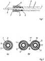
- the optical waveguidecomprises an optical fiber 1 with a core and a cladding polymeric material and a tube 2 made of metal, which provides mechanical protection for the Fiber 1 and an electrical conductor forms the wall of the tube 2 is radial Stiffening and improvement of flexibility curled, the curl in the form of a Helix 3 runs around the axis 4 of the optical waveguide.
- the tube 2On the outside is the tube 2 provided with insulation 5, such as a layer of polyethylene. It prevents Short circuits between the tube 2 and a support part, such as the body part Vehicle on which it is installed
- the tube 2is connected to an end piece 6, for example is crimped or screwed to the helical corrugation also made of metal and used for mechanical fixing and electrical Contacting the tube 2.
- a central opening 7allows the fiber 1 to Lead connection to other components out of pipe 2. This prevents one Protective cover 8 made of an opaque polymer that damage the fiber 1st or there is an incidence of light in this area. Also inside the tube 2 is one Protective cover 8 is useful to avoid abrasion of the fiber 1.
- An overmolding 9 shown in broken linesconnects the end piece 6 Moisture-proof with the insulation 5. It is also possible to use elements in this way a connector, such as projections for guiding or locking.
- FIG. 2ashows a cross section through the optical waveguide in FIG. 1 central fiber 1 with its protective cover 8, the tube 2 and the outer insulation 5.
- Fig. 2bshows the cross section through a hybrid cable with two optical fibers the optical fibers 10, 11. They are each in a protective cover 12, 13 and are arranged in metal tubes 14, 15. Both tubes 14, 15 are from one common insulation 16 enclosed. A constriction 17 with a notch 18 enables the simple separation of both optical fibers.
- a connected electro-optical componentdifferent Supply voltages via the two mutually insulated pipes 14, 15 are supplied become. This allows the two fibers 10, 11, two independent of each other Provide systems for optical data transmission, for example to ensure security increase.
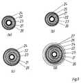
- Fig. 3cross sections through hybrid cables with several electrical conductors are shown.
- the cables in drawing files (a) and (b)have a diameter of for example 3-4 mm each from a polymeric optical fiber 20, in a smooth inner tube 21, which is guided coaxially in an outer corrugated tube 22, both tubes 21, 22nd are made of metal and serve as electrical conductors through an intermediate one arranged foamed or compact insulation 23 are spaced apart.
- the tube 22is also provided with insulation 24.
- the inner tube 21can be an open one Have longitudinal gap 25. Thus, it can be easily formed by mechanical shaping Manufacture way from a metal strip without the need to To close longitudinal gap 25, for example by welding. By using two However, the protection of the fiber 20 can be carried out all round closed tubes 21, 22 improve.
- 3cshows an embodiment of the hybrid cable with two corrugated metal tubes 21, 22. In this way there is good flexibility even with larger diameters of the cable reachable.
- the outer corrugated tube 26is preferably located on the electrical potential of the body of a vehicle or the frame of a Device and serves as a return line. In this case, an outer jacket 27 be dispensed with, while such a jacket 27 is in danger of corrosion or deviating potential of the corrugated tube 26 proves to be expedient.
- the optical waveguides according to the invention with a star couplerare preferred connected, as shown in Figure 4.
- the couplercomprises several, four in the example Connections 30-33, each of which can be connected to an optical waveguide according to the invention are.
- an optical coupling element 34for example one Lens, which enables the coupling and decoupling of light into the fiber 1
- the coupling elements 34 of all connectionsare interconnected by an optical one Star coupler, preferably connected to an optical gain medium.
- the coupling element 34is concentric with three electrical contacts 35-37 surround.
- the inner contact 35serves to connect an electrical one Conductor with a first supply voltage (e.g. 12 V), the contact 35 for connection a second electrical conductor with a second supply voltage (e.g. 42 V) and the contact 37 as a ground contact.
- Similar contacts 35 - 37 of all connections 30 - 33are electrically connected to each other.
- the contacts 35 - 37are useful to the contacts 35 - 37 as Form plug contacts, in which, for example, the end piece of a Optical fiber can be inserted
- the contacts 35 - 37 as Threadsare formed, in which there is an end piece or a spiral corrugated can screw in the electrical conductor of an optical fiber Coupler the connection for all electrical conductors of the optical fibers to the Power supply, which takes place via an electrical supply line 38 of the coupler.
- FIG. 5shows a further exemplary embodiment of an optical waveguide according to the teaching of Invention shown.
- the foam layer 39consists of Polyethylene, polypropylene or other temperature-resistant plastic.
- the degree of frothingshould survey over 50%, preferably up to 85%.
- the wall thickness of the Foam layer 39is preferably 0.3 to 2.0 mm.
- the main advantage of Foam layercan be seen in the fact that it has succeeded in the optical waveguide Use ambient temperatures up to 130 ° C.
- the foam layerforms moreover a cushion for the fiber. For this it is advantageous if the foam has a soft mechanical characteristic that does not contribute to an increase in damping the fiber leads. It ensures that mechanical forces are neither radial nor axial Act in the direction of the fiber.
- the productionis advantageously carried out by extrusion of a foamable Plastic layer on the fiber, the foaming process chemically or physically is carried out.
- a metal bandis inserted lengthwise around the of the foam layer 39 provided fiber 1 to a tube with a longitudinal slot shaped.
- the tubecan be reduced to a small one Diameter can be pulled down and is then used in the same operation an annular or helical corrugation.
- onecan Plastic jacket to be extruded onto the corrugated pipe.
Landscapes
- Physics & Mathematics (AREA)
- General Physics & Mathematics (AREA)
- Optics & Photonics (AREA)
- Communication Cables (AREA)
- Optical Fibers, Optical Fiber Cores, And Optical Fiber Bundles (AREA)
Abstract
Description
Translated fromGermanDie Erfindung bezieht sich auf einen Lichtwellenleiter, insbesondere für ein Fahrzeug, miteiner optischen Faser die aus polymerem Material besteht, sowie mit einer Schutzlage,welche die Faser umschließt.The invention relates to an optical waveguide, in particular for a vehiclean optical fiber made of polymeric material and a protective layer,which encloses the fiber.
Im Fahrzeugbau besteht das Problem, daß der zunehmende Einsatz elektrischer undelektronischer Komponenten in Fahrzeugen zu einem starken Anwachsen derzumAnschluß notwendigen Leitungen geführt hat. Um die Leitungslänge und ihr Gesamtgewichtzu verringern und den Aufbau sowie die Konfektionierung des Kabelbaums zuvereinfachen, sind daher Bussysteme entwickelt worden. Sie ermöglichen dieDatenübertragung zwischen mehreren Komponenten über eine gemeinsame Leitung undreduzieren somit die erforderliche Leitungszahl.In vehicle construction there is the problem that the increasing use of electrical andelectronic components in vehicles to a strong growthConnection necessary lines has led. The cable length and its total weightto reduce and the construction and assembly of the wiring harnesssimplify, bus systems have therefore been developed. They make that possibleData transmission between several components via a common line andthus reduce the number of lines required.
Hohe Übertragungsraten lassen sich insbesondere durch Bussysteme mit Lichtwellenleiternerreichen, die mit optischen oder elektrooptischen Komponenten zusammenwirken. Dieoptischen Fasern der Lichtwellenleiter umfassen einen lichtleitenden Kern, der von einemMantel zur Führung des Lichtes umschlossen ist, sowie ggf. eine oder mehrere äußereSchutzschichten. Im Fahrzeugbau erweisen sich Lichtwellenleiter aus polymeren optischenFasern als vorteilhaft, etwa aus Polymethylmethacrylat (PMMA) und/oder fluoriertemPMMA. Geeignet sind z. B. Gradientenindexfasern mit einem Durchmesser von 1 mm.Gegenüber Glasfasern bieten sie die Vorteile mechanischer Robustheit, der einfachenHandhabbarkeit und Konfektionierung aufgrund des großen Durchmessers sowie die Möglichkeit des Betriebs mit sichtbarem Licht. Die im Vergleich zu Glas höhere Dämpfungist dagegen bei den kurzen Übertragungswegen in Fahrzeugen von untergeordneterBedeutung.High transmission rates can be achieved in particular through bus systems with optical fibersachieve that interact with optical or electro-optical components. Theoptical fibers of the optical waveguides comprise a light-guiding core, which is made by aJacket for guiding the light is enclosed, and possibly one or more outerProtective layers. In vehicle construction, optical fibers made of polymeric optical materials have been foundFibers as advantageous, for example from polymethyl methacrylate (PMMA) and / or fluorinatedPMMA. Are suitable for. B. gradient index fibers with a diameter of 1 mm.Compared to glass fibers, they offer the advantages of mechanical robustness, the simple oneManageability and assembly due to the large diameter and thePossibility of operating with visible light. The higher damping compared to glassis, however, of secondary importance in the short transmission paths in vehiclesImportance.
Als nachteilig erweist sich jedoch, daß zusätzliche Energieleitungen für die elektrischeSpannungsversorgung der Sensoren und Aktuatoren notwendig sind. Zudem können dieoptischen Eigenschaften gebräuchlicher Polymerfasern durch Aufnahme von undchemische Reaktion mit Substanzen aus ihrer Umgebung erheblich beeinträchtigt oderzerstört werden. Neben den Betriebsflüssigkeiten, z. B. Schmiermitteln oder Kraftstoffen, istdie Vielzahl der in Fahrzeugen eingesetzten Kunststoffe problematisch, die beständigSubstanzen abgeben, etwa nach Abschluß des Herstellungsprozesses ausgasende Edukteoder Treibmittel. Zudem ist in aller Regel ein guter Schutz der Fasern vor Feuchtigkeit undthermischen Belastungen, speziell beim Einsatz im Motorraum oder bei der Anbindung vonSensoren oder Aktuatoren außerhalb der Fahrgastzelle erforderlich. Die im Stande derTechnik übliche Führung der Fasern in einer Schutzhülle oder einem Röhrchen ausKunststoff ist für diese Zwecke unzureichend, da Polymere in der Regel nicht hinreichendgasdicht sind.It proves disadvantageous, however, that additional power lines for the electricalPower supply to the sensors and actuators are necessary. In addition, theoptical properties of common polymer fibers by absorption of andchemical reaction with substances from their environment is significantly impaired orbe destroyed. In addition to the operating fluids, e.g. B. lubricants or fuelsthe large number of plastics used in vehicles is problematic, the permanentRelease substances, such as starting materials that outgas after completion of the manufacturing processor blowing agent. In addition, there is usually good protection of the fibers from moisture andthermal loads, especially when used in the engine compartment or when connectingSensors or actuators required outside the passenger compartment. The capable ofTechnique usual guidance of the fibers in a protective cover or a tubePlastic is inadequate for these purposes, since polymers are usually not sufficientare gastight.
Weiterhin ist es bekannt, Metallrohre als Komponenten elektrischer Kabel mit einer Wellungzu versehen, um ihre Biegsamkeit und Querdruckstabilität zu verbessern. Die Wellungerfolgt im Winkel zur Längsachse des Rohres. Dabei sind sowohl schraubenförmigeWellungen mit im spitzen Winkel zur Rohrlängsachse verlaufenden Wellenkämmen alsauch rechtwinklig zur Achse ausgerichtete Wellungen aus geschlossenen Ringengebräuchlich. Durch Variation von Tiefe und Abstand der Wellen lassen sich diemechanischen Eigenschaften des Rohres, etwa die Biegsamkeit, in weiten Grenzeneinstellen.Furthermore, it is known to use metal pipes as components of electrical cables with a corrugationto improve their flexibility and lateral pressure stability. The curltakes place at an angle to the longitudinal axis of the tube. Both are helicalCorrugations with wave crests running at an acute angle to the pipe longitudinal axis asalso corrugations of closed rings oriented at right angles to the axisin use. By varying the depth and spacing of the waves, themechanical properties of the pipe, such as flexibility, within wide limitsto adjust.
Vor diesem Hintergrund hat sich die Erfindung zur Aufgabe gestellt einen Lichtwellenleiterzu entwickeln, der sicher vor Umwelteinflüssen geschützt ist und eine einfache Verbindungvon signalverarbeitenden Kömponenten mit einer minimalen Zahl von Leitungen ermöglichtAgainst this background, the invention has the task of an optical waveguideto develop, which is safely protected from environmental influences and a simple connectionsignal processing components with a minimal number of lines
Diese Aufgabe wird erfindungsgemäß dadurch gelöst, daß die Schutzlage ein Rohr ausMetall ist, das Rohr eine Wellung im Winkel zu seiner Längsachse aufweist, das Rohr einenelektrischen Leiter bildet und mit einer außenseitigen Isolierung versehen ist.This object is achieved in that the protective layer is a tubeMetal is, the tube has a corrugation at an angle to its longitudinal axis, the tube oneforms electrical conductor and is provided with external insulation.
Bei der Erfindung wird im Lichtwellenleiter eine polymeroptische Faser verwendet, etwaeine Gradientenindex- oder Stufenindexfaser, die aus PMMA, fluoriertem PMMA odereinem anderen Kunststoff mit geeigneten optischen Eigenschaften besteht DerAußendurchmesser der Faser beträgt bevorzugt etwa 1 mm, wobei der Kemdurchmesserden Manteldurchmesser meist deutlich übersteigt, so daß die einfache Lichteinkopplungund Verbindung der Faser gewährleistet ist Denkbar ist sowohl, die Faser bei einereinzelnen Wellenlänge zu betreiben als auch mehrere unterschiedliche Lichtwellenlängenüber eine Faser zu übertragen.In the invention, a polymer-optical fiber is used in the optical waveguide, for examplea gradient index or step index fiber made of PMMA, fluorinated PMMA oranother plastic with suitable optical propertiesThe outer diameter of the fiber is preferably about 1 mm, the core diameterusually exceeds the cladding diameter significantly, so that the simple coupling of lightand connection of the fiber is guaranteedto operate single wavelength as well as several different light wavelengthsto transmit over a fiber.
Die Faser ist umlaufend von einem Wellrohr aus Metall umschlossen, dessen Wellung z. B.aus geschlossenen Ringen oder schraubenförmig ausgebildet ist. Tiefe und Periode derWellung sind derart eingestellt, daß die elastischen Eigenschaften des Metalls einensicheren Schutz der Faser sowohl vor radialen als auch axialen Belastungen gewährleisten.Die Faser liegt dabei frei im Rohr, dessen Innendurchmesser den Faserdurchmesserübersteigt Daher ist eine Kraftübertragung von axial auf das Rohr wirkendenZugbelastungen auf die Faser ausgeschlossen. Die Wellung ermöglicht eine hoheBiegsamkeit des Rohres mit einem vorgegebenen minimalen Biegeradius, der einAbknicken der Faser und damit eine Beeinträchtigung ihrer optischen Eigenschaftenausschließt Bevorzugt beträgt der minimale Biegeradius des Rohres zumindest das 10-fachedes Faserdurchmessers. Weiterhin bildet das Metallrohr eine dampfdichteSperrschicht um die Faser, die Schädigungen durch Lösungsmittel oder gasförmigeSubstanzen aus der Umgebung ausschließt. Denkbar ist, innerhalb des Rohres einegelförmige oder flüssige Füllmasse mit beispielsweise hydrophoben oder SchadstoffabsorbierendenEigenschaften vorzusehen, in welche die Faser eingebettet istThe fiber is encircled by a corrugated metal tube, the corrugation z. B.is formed from closed rings or helical. Depth and period ofCorrugation is set so that the elastic properties of the metal uniteEnsure safe protection of the fiber against both radial and axial loads.The fiber lies freely in the tube, the inside diameter of which is the fiber diameterTherefore, there is a power transmission from axially acting on the pipeTensile loads on the fiber excluded. The corrugation enables a high oneFlexibility of the tube with a predetermined minimum bending radius, the oneKinking the fiber and thus impairing its optical propertiesexcludes The minimum bending radius of the tube is preferably at least 10 timesof the fiber diameter. Furthermore, the metal tube forms a vapor-tight oneBarrier layer around the fiber, the damage by solvent or gaseousExcludes substances from the environment. Is conceivable within the tubegel-like or liquid filling compound with, for example, hydrophobic or pollutant-absorbingTo provide properties in which the fiber is embedded
Außenseitig ist das Metallrohr mit einer elektrischen Isolierung versehen, beispielsweiseeiner Schicht aus einem Polymer, etwa einem Polyolefin wie z. B. Polyethylen. Nebenkompakten Polymeren sind auch geschäumte Werkstoffe für die Isolierung geeignet, etwaein Polyurethanschaum. Zweckmäßig ist es, für die Isolierung sowie für einen ggf.vorhandenen äußeren Mantel halogenfreie und/ oder schwer entflammbare Materialien zuverwenden, um die Sicherheit im Brandfall zu verbessern. Mit der Isolierung entsteht einelektrischer Leiter, der insbesondere zur Energieversorgung derjenigen Komponentendient, die mit der optischen Faser verbunden sind. Somit bildet der Lichtwellenleiter mitseinem Schutzrohr ein Hybridkabel, das gleichzeitig zur Energie- und Datenübertragunggeeignet ist Grundsätzlich ist es auch möglich, elektrische Signale über das Wellrohr zu übertragen. Als Material des Rohres sind insbesondere gut leitfähige Metalle, wie Kupferoder Aluminium, geeignet oder - in Abhängigkeit von den gewünschten elektrischen undmechanischen Eigenschaften - Legierungen, etwa Messing oder Bronze. Sofern diemechanische Festigkeit im Vordergrund steht, ist grundsätzlich auch Stahl denkbar. Dabeiverhindert die elektrische Isolierung eine Kontaktkorrosion mit Karosserie- oder andererenTrägerteilen, auf denen der Leiter verlegt ist. Die Wandstärke des Metallrohres beträgtzweckmäßig 100 µm bis einige 100 µm, wobei ein für die Stromübertragung hinreichenderLeitungsquerschnitt der Wandung notwendig ist, der vorzugsweise im Bereich eines biseiniger mm2 liegt.On the outside, the metal tube is provided with electrical insulation, for example a layer of a polymer, such as a polyolefin such as. B. polyethylene. In addition to compact polymers, foamed materials are also suitable for insulation, such as a polyurethane foam. It is expedient to use halogen-free and / or flame-retardant materials for the insulation and for any outer sheath that may be present, in order to improve safety in the event of a fire. The insulation creates an electrical conductor which is used in particular to supply energy to those components which are connected to the optical fiber. The optical waveguide and its protective tube thus form a hybrid cable that is simultaneously suitable for energy and data transmission. In principle, it is also possible to transmit electrical signals via the corrugated tube. Metals which are highly conductive, such as copper or aluminum, are particularly suitable as the material of the tube or, depending on the desired electrical and mechanical properties, alloys, such as brass or bronze. If mechanical strength is paramount, steel is also conceivable. The electrical insulation prevents contact corrosion with body or other support parts on which the conductor is laid. The wall thickness of the metal tube is expediently 100 μm to a few 100 μm, a line cross-section of the wall sufficient for current transmission being necessary, which is preferably in the range from one to a few mm2 .
Der vorgeschlagene Lichtwellenleiter zeichnet sich durch einen sicheren Schutz deroptischen Faser gegenüber Umwelteinflüssen, wie mechanischen Belastungen in QuerundLängsrichtung, hohen Temperaturen, chemischen Substanzen und Vibrationen aus.Weiterhin ist ein guter Nagetierschutz gegeben. Wechselwirkungen der übertragenenSignale mit äußeren elektromagnetischen Feldern sind dagegen ausgeschlossen. DieHandhabung des Lichtwellenleiters ist einfach, wobei das Metallrohr die Polymerfaser vorBeschädigung bei der Verarbeitung und Verlegung schützt.The proposed optical fiber is characterized by safe protection of theoptical fiber against environmental influences, such as mechanical loads in transverse andLongitudinal direction, high temperatures, chemical substances and vibrations.Good rodent protection is also provided. Interactions of the transferredHowever, signals with external electromagnetic fields are excluded. TheHandling the optical fiber is easy, with the metal tube facing the polymer fiberProtects damage during processing and laying.
Der Lichtwellenleiter ist für die Verbindung von Komponenten bevorzugt, die sowohl eineelektrische Energieversorgung als auch eine optische Signalübertragung erfordern.Denkbar ist sein Einsatz insbesondere in modularen Systemen, wobei ein Multiplexbetriebdes Lichtwellenleiters bei mehreren Wellenlängen von Vorteil ist. Neben dem Fahrzeugbau,beispielsweise dem Kraftfahrzeug-, Flugzeug- oder Schiffbau, ist der Einsatz auch inanderen kleinräumigen Bereichen zweckmäßig, die einen besonderen Schutz desLichtwellenleiters erfordern, etwa im Maschinenbau oder chemischen Anlagen. Speziell imFahrzeugbau ist es sowohl möglich, den erfindungsgemäßen Lichtwellenleiter für dieVerbindung von Informationssystemen einzusetzen, z. B. Telefon, Radio oderNavigationssystemen, als auch in Steuerungssystemen mit Sensoren und Aktuatoren. Dieverwendeten Netzstrukturen sind dabei beliebig und können beispielsweise ring- odersternförmig sein.The optical waveguide is preferred for the connection of components that are bothrequire electrical power supply as well as an optical signal transmission.Its use is particularly conceivable in modular systems, with a multiplex operationof the optical waveguide is advantageous at several wavelengths. In addition to vehicle construction,For example, the automotive, aircraft or shipbuilding, the use is also inother small-scale areas appropriate, the special protection of theOptical fiber, for example in mechanical engineering or chemical plants. Especially inVehicle construction, it is both possible to use the optical waveguide according to the inventionUse connection of information systems, e.g. B. telephone, radio orNavigation systems, as well as in control systems with sensors and actuators. TheNetwork structures used are arbitrary and can for example be ring orbe star-shaped.
In einer vorteilhaften Ausgestaltung der Erfindung beträgt der Außendurchmesser desgewellten Metallrohres bis zu 6 mm, vorzugsweise 2-4 mm. Auf diese Weise ist eine guteFlexibilität des Rohres bei hoher radialer Belastbarkeit und hinreichendem elektrischenLeitungsquerschnitt erreichbar. Entsprechend vereinfacht sich die Handhabung des Lichtwellenleiters. Vorzugsweise umschließt das Metallrohr dabei eine einzelne optischeFaser.In an advantageous embodiment of the invention, the outer diameter of thecorrugated metal tube up to 6 mm, preferably 2-4 mm. That way is a good oneFlexibility of the tube with high radial load capacity and sufficient electricalCable cross-section attainable. Accordingly, the handling of theOptical fiber. The metal tube preferably encloses a single optical oneFiber.
Als Schutzrohr bietet sich aufgrund der einfachen Fertigung ein längsnahtgeschweißtesMetallrohr an. Seine Herstellung erfolgt bevorzugt, indem ein Metallband um die optischeAder zu einem Rohr geformt wird, dessen Innendurchmesser den Außendurchmesser derAder übersteigt. Nachfolgend wird das Rohr entlang seiner Kanten verschweißt, wozuspeziell eine Laserverschweißung geeignet ist. Abschließend erfolgen die Wellung desRohres und seine Isolierung.Due to the simple manufacture, a longitudinally welded tube is available as a protective tubeMetal pipe. It is preferably made by placing a metal band around the optical oneVein is formed into a tube, the inside diameter of which is the outside diameterCore exceeds. The pipe is then welded along its edges, for whatlaser welding is particularly suitable. Finally, the corrugation of theRohres and its insulation.
Vielfach ist es zweckmäßig, daß die optische Faser mit einer äußeren Schutzhülle auspolymerem Material versehen ist, die den Fasermantel umschließt und in der Regel darananliegt. Von Vorteil sind insbesondere lichtabsorbierende Schutzhüllen, die eine Störungder übertragenen Signale durch Lichteinfall in den Bereichen vermeiden, in denen die Faseraus dem Metallrohr herausgeführt ist. Weiterhin bildet die Schutzhülle einen mechanischenSchutz der Faser sowohl in Bereichen, in denen sie aus dem Metallrohr herausgeführt ist,als auch gegenüber Abrieb in dessen Innerem, etwa im Fall häufiger Vibrationen.In many cases, it is expedient for the optical fiber to have an outer protective coveris provided polymeric material that encloses the fiber jacket and usually attached to itis present. Of particular advantage are light-absorbing protective covers that cause interferenceAvoid the transmitted signals by incidence of light in the areas where the fiberis led out of the metal tube. Furthermore, the protective cover forms a mechanical oneProtection of the fiber both in areas where it is led out of the metal tubeas well as against abrasion inside, for example in the case of frequent vibrations.
Da die optische Faser im Inneren des Rohres sicher geschützt ist, kann der Hybridleiter wieein herkömmlicher elektrischer Leiter gehandhabt werden. Sowohl das Metallrohr als auchseine Isolierung läßt sich wasserdicht und/oder ortsfest mit Verbindungselementenverbinden. Zu Verbindungselementen zählen sämtliche Komponenten, die bei derKonfektionierung am Leiter fixiert werden. Beispiele sind elektrische Verbinder, optischeVerbinder oder Hybridverbinder für die Leiter, Dichtungen oder Tüllen zur Durchführungdurch Wandungen, etwa zwischen dem Motorraum und dem Fahrgastraum einesKraftfahrzeuges, oder Befestigungselemente zur Anbringung oder Zugentlastung.Geeignete Verfahren zur wasserdichten bzw. ortsfesten Verbindung sind zum BeispielVerschweißen, Verlöten, Crimpen, Verkleben, Angießen oder Anspritzen oder dieVerwendung von federnden oder Klemmverbindungen, z. B. Schneidklemmverbindungen.Auch die elektrische Verbindung des Wellrohres mit anderen Komponenten läßt sich aufdiese Weise herstellen.Since the optical fiber inside the tube is safely protected, the hybrid conductor can be used likea conventional electrical conductor can be handled. Both the metal pipe as wellits insulation can be waterproof and / or stationary with connecting elementsconnect. Fasteners include all components that are used in theThe assembly must be fixed on the conductor. Examples are electrical connectors, opticalConnector or hybrid connector for the conductors, seals or grommets for the bushingthrough walls, such as between the engine compartment and the passenger compartmentMotor vehicle, or fasteners for attachment or strain relief.Suitable methods for the watertight or fixed connection are, for exampleWelding, soldering, crimping, gluing, casting or spraying or theUse of spring or clamp connections, e.g. B. insulation displacement connections.The electrical connection of the corrugated pipe to other components can also be donecreate this way.
Bevorzugt ist das Schutzrohr endseitig mit einem Abschlußstück versehen, das eineÖffnung zum Herausführen der optischen Faser aufweist. Zweckmäßig weist die Öffnungeinen größeren Durchmesser als die Faser auf, so daß ein Spalt zwischen beiden vorhanden ist. Bei Bedarf ist ein Verschließen des Spaltes, etwa mit einer Vergußmasse,möglich. Das Abschlußstück vereinfacht eine mechanische Festlegung des Schutzrohressowie dessen elektrische Kontaktierung, sofern es aus einem leitfähigen Werkstoff,insbesondere einem Metall besteht. Zur Fixierung bietet es sich an, das Abschlußstück aufdas Schutzrohr zu crimpen. Bei spiralförmiger Wellung des Rohres ist auch ein Innen- oderAußengewinde auf dem Abschlußstück von Vorteil, mit dem es sich auf die Wellung desSchutzrohres aufschrauben bzw. in dessen Öffnung einschrauben läßt.Preferably, the protective tube is provided at the end with an end piece, the oneHas opening for leading out the optical fiber. The opening expediently pointsa larger diameter than the fiber, leaving a gap between the twois available. If necessary, closing the gap, for example with a casting compound,possible. The end piece simplifies mechanical fixing of the protective tubeand its electrical contact, if it is made of a conductive material,in particular a metal. It is advisable to fix the end piece onto crimp the protective tube. In the case of spiral corrugation of the tube there is also an inside orExternal thread on the end piece is advantageous, with which it relates to the corrugation of theScrew on the protective tube or screw it into its opening.
Bevorzugt umfaßt ein Kabel mit dem erfindungsgemäßen Lichtwellenleiter zumindest einenweiteren, gegen das Schutzrohr des Lichtwellenleiters isolierten, elektrischen Leiter. Ereignet sich als elektrische Rückleitung, wenn die Karosserie, ein Rahmen oderTrägerkörper eines Fahrzeuges bzw. einer Vorrichtung als elektrische Rückleitungungeeignet ist, also etwa bei Fahrzeugen mit einer Kunststoffkarosserie. Ebenso lassensich einem Verbraucher auf diese Weise unterschiedliche Versorgungsspannungenzuführen, so daß beispielsweise Kraftfahrzeugbordnetze mit mehreren Spannungenmöglich sind. Als Material der Leiter sind zum Beispiel Metalle wie Kupfer oder Aluminiumgeeignet Im einfachsten Fall sind der oder die weiteren Leiter Drähte oder Litzen.A cable with the optical waveguide according to the invention preferably comprises at least onefurther electrical conductor insulated against the protective tube of the optical waveguide. Heis suitable as an electrical return line if the body, a frame orCarrier body of a vehicle or a device as an electrical return lineis unsuitable, for example in vehicles with a plastic body. Leave as welldifferent supply voltages to a consumer in this wayfeed so that, for example, vehicle electrical systems with multiple voltagespossible are. The material of the conductor is, for example, metals such as copper or aluminumsuitable In the simplest case, the other conductor or conductors are wires or strands.
Als zweckmäßig erweist sich die Anordnung des weiteren Leiters im Inneren des Rohres.Auf diese Weise entsteht ein Kabel mit geringem Querschnitt. Alternativ besteht dieMöglichkeit, das Schutzrohr des Lichtwellenleiters und die weiteren elektrischen Leiterparallel in einem gemeinsamen Mantel zu führen.The arrangement of the further conductor in the interior of the tube proves to be expedient.This creates a cable with a small cross-section. Alternatively, there isPossibility of the protective tube of the optical fiber and the other electrical conductorsto run in parallel in a common coat.
Besonders geeignet als weiterer Leiter ist ein Rohr. Vorzugsweise verläuft es koaxial zumSchutzrohr des Lichtwellenleiters. In diesem Fall wird die optische Faser von beiden Rohrenumschlossen, so daß sich ihr Schutz verbessert. Als inneres Rohr ist ein Rohr mit glatterOberfläche denkbar, da die Biegsamkeit des Kabels insbesondere durch die mechanischenEigenschaften des äußeren Rohres bestimmt wird. Damit ist ein besonders geringerQuerschnitt des Kabels erreichbar. Weiterhin kann eines, vorzugsweise das innere Rohr,einen offenen Längsspalt aufweisen, um die Fertigung zu vereinfachen. Die mechanischeStabilität und radiale Gasdichtigkeit wird dabei sichergestellt, indem das andere Rohr, etwadurch Verschweißung, umlaufend geschlossen ist.A pipe is particularly suitable as a further conductor. It is preferably coaxial with theProtection tube of the optical fiber. In this case the optical fiber is from both tubesenclosed so that their protection improves. The inner tube is a tube with a smoother oneSurface conceivable, since the flexibility of the cable is particularly due to the mechanicalProperties of the outer tube is determined. This is a particularly low oneCross section of the cable accessible. Furthermore, one, preferably the inner tube,have an open longitudinal gap to simplify production. The mechanicalStability and radial gas tightness is ensured by the other tube, for exampleis closed all round by welding.
Um eine hohe Flexibilität des Kabels zu erzielen, werden sowohl für das Schutzrohr alsauch für den oder die weiteren Leiter Wellrohre verwendet.In order to achieve a high flexibility of the cable, both for the protective tube andalso used for the other conductor (s).
Zur gegenseitigen Isolierung der elektrischen Leiter sind neben kompakten Materialien auchSchaumstoffe geeignet, wobei durch physikalische Mischung hergestellte Schäume, zumBeispiel ein Polypropylenschaum, oder durch chemische Reaktion erzeugte Schaumstoffeverwendbar sind. Schaumstoffisolierungen reduzieren das Gewicht des Kabels beigünstigen elektrischen Eigenschaften. Sie bieten sich speziell als gegenseitige Isolierungkoaxial ineinander verlaufender Rohre an.In addition to compact materials, there is also a mutual insulation of the electrical conductorsSuitable foams, foams produced by physical mixing, forExample a polypropylene foam, or foams produced by chemical reactionare usable. Foam insulation reduces the weight of the cablefavorable electrical properties. They are particularly useful as mutual insulationcoaxial pipes.
In vielen Fällen ist es vorteilhaft, daß ein Kabel zumindest zwei polymeroptische Fasern mitjeweils einem Schutzrohr umfaßt. Auf diese Weise ist es beispielsweise möglich, ausSicherheitsgründen voneinander unabhängige optische Leiter gemeinsam zu führen. Fernerlassen sich durch gegeneinander isolierte Schutzrohre unterschiedlicheVersorgungsspannungen zu einem Verbraucher leiten oder eine Hin- und Rückleitung zurSpannungsquelle herstellen. Sind mehr als zwei Schutzrohre miteinander verbunden, istihre Anordnung in einer Ebene zweckmäßig, um die Biegsamkeit des Kabels zu erhalten.Zur Verbindung der Rohre bietet es sich an, ihre Isolierungen miteinander zu verkleben,einen gemeinsamen Mantel um die Isolierungen zu extrudieren oder einezusammenhängende Isolierung um die Schutzrohre zu extrudieren. Zweckmäßig ist eineEinkerbung oder Engstelle, die im Mantel bzw. der Isolierung zwischen den Schutzrohrenangeordnet ist und ihre Trennung erleichtert.In many cases it is advantageous for a cable to have at least two polymer-optical fiberseach includes a protective tube. In this way it is possible, for exampleTo lead independent optical conductors together for safety reasons. Furthercan be differentiated by mutually insulated protective tubesLead supply voltages to a consumer or a forward and return line toEstablish voltage source. Are more than two protective tubes connected to one anothertheir arrangement in one plane is appropriate in order to maintain the flexibility of the cable.To connect the pipes, it makes sense to glue their insulation together,a common jacket to extrude the insulation or acontinuous insulation to extrude the protective tubes. One is appropriateNotch or constriction in the jacket or insulation between the protective tubesis arranged and their separation easier.
Obwohl der erfindungsgemäße Lichtwellenleiter auch zur Verbindung einzelnerKomponenten geeignet ist, wird insbesondere vorgeschlagen, ihn als Bestandteil desKabelbaums einer Vorrichtung oder eines Fahrzeuges einzusetzen. Damit lassen sichsowohl das Gesamtgewicht als auch die Gesamtlänge der Adern des Kabelbaumserheblich verringern.Although the optical waveguide according to the invention also for connecting individualComponent is suitable, it is proposed in particular as part of theUse a device or vehicle wiring harness. With that you canboth the total weight and the total length of the wires of the wiring harnessreduce significantly.
Zur Verbindung der optischen Fasern von erfindungsgemäßen Lichtwellenleiternuntereinander ist ein optischer Koppler zweckmäßig. Von Vorteil sind speziell Stemkoppler,welche die Verbindung mehrerer Lichtwellenleiter untereinander gestatten.For connecting the optical fibers of optical fibers according to the inventionwith each other, an optical coupler is appropriate. Stem couplers are particularly advantageous,which allow the connection of several optical fibers to each other.
Um bei längeren Übertragungswegen oder der Kopplung mehrerer Lichtwellenleiter einehinreichende Signalintensität zu gewährleisten, ist ein Koppler mit einem optisch aktivenKoppelmedium von Vorteil, das eine Verstärkung der optischen Signale bewirkt.In order to achieve a longer transmission path or the coupling of several optical fibersTo ensure sufficient signal intensity is a coupler with an optically activeCoupling medium advantageous, which causes an amplification of the optical signals.
Der Koppler bietet sich auch für die Kontaktierung, speziell die Spannungsversorgung derelektrischen Leiter des Lichtwellenleiters an. Diese Ausgestaltung ist insbesondere beieinem aktiven Koppler zweckmäßig, der eine Spannungsversorgung des optischenVerstärkers erfordert. Daneben ermöglichen miteinander verbundene Kontakte desKopplers die Verbindung der elektrischen Leiter untereinander. Auf diese Weise ist lediglichein elektrischer Anschluß für in unterschiedlichen Lichtwellenleitern geführte elektrischeLeiter erforderlich. Bevorzugt umfaßt der Koppler entsprechend der Ausgestaltung derelektrischen Leiter eine Spannungsversorgung sowie gegebenenfalls einen Masseanschlußund weitere Spannungsversorgungen mit unterschiedlichem Potential.The coupler is also suitable for contacting, especially the power supply of theelectrical conductor of the optical fiber. This configuration is particularly the case withexpediently an active coupler which supplies the optical powerAmplifier. Connected contacts also allow theCoupler the connection of the electrical conductors to each other. This way is onlyan electrical connection for electrical in different optical fibersLadder required. According to the design of the coupler preferably compriseselectrical conductor a voltage supply and possibly a ground connectionand other power supplies with different potential.
Im folgenden Beschreibungsteil sind Ausführungsbeispiele der Erfindung näher erläutert.Die Zeichnung zeigt in prinzipienhafter Darstellung
Der Lichtwellenleiter umfaßt eine optische Faser 1 mit einem Kern und einem Mantel auspolymerem Material sowie ein Rohr 2 aus Metall, das einen mechanischen Schutz derFaser 1 und einen elektrischen Leiter bildet Die Wandung des Rohres 2 ist zur radialenAussteifung und Verbesserung der Biegsamkeit gewellt, wobei die Wellung in Form einerSchraubenlinie 3 um die Achse 4 des Lichtwellenleiters verläuft. Außenseitig ist das Rohr 2mit einer Isolierung 5 versehen, etwa einer Schicht aus Polyethylen. Sie verhindertKurzschlüsse zwischen dem Rohr 2 und einem Trägerteil, etwa dem Karosserieteil einesFahrzeuges, auf dem es verlegt istThe optical waveguide comprises an
Endseitig ist das Rohr 2 mit einem Abschlußstück 6 verbunden, das beispielsweiseaufgecrimpt oder mit der schraubenlinienförmigen Wellung verschraubt ist Es bestehtgleichfalls aus Metall und dient zur mechanischen Festlegung und elektrischenKontaktierung des Rohres 2. Eine zentrale Öffnung 7 ermöglicht es, die Faser 1 zumAnschluß an andere Komponenten aus dem Rohr 2 herauszuführen. Dabei verhindert eineSchutzhülle 8 aus einem lichtundurchlässigen Polymer, daß eine Beschädigung der Faser 1 oder ein Lichteinfall in diesen Bereich erfolgt. Auch im Inneren des Rohrs 2 ist eineSchutzhülle 8 zweckmäßig, um einen Abrieb der Faser 1 zu vermeiden.At the end, the
Eine gestrichelt dargestellte Umspritzung 9 verbindet das Abschlußstück 6feuchtigkeitsdicht mit der Isolierung 5. Ebenso ist es möglich, auf diese Weise Elementeeines Steckerverbinders, etwa Vorsprünge zur Führung oder Verrieglung, anzuformen.An
Fig. 2a zeigt einen Querschnitt durch den Lichtwellenleiter in Fig. 1. Erkennbar sind diezentrale Faser 1 mit ihrer Schutzhülle 8, das Rohr 2 und die äußere Isolierung 5.FIG. 2a shows a cross section through the optical waveguide in FIG. 1
Fig. 2b gibt den Querschnitt durch ein Hybridkabel wieder, das zwei Lichtwellenleiter mitden optischen Fasern 10, 11 umfaßt. Sie befinden sich jeweils in einer Schutzhülle 12, 13und sind in Metallrohren 14, 15 angeordnet. Beide Rohre 14, 15 werden von einergemeinsamen Isolierung 16 umschlossen. Eine Engstelle 17 mit einer Kerbe 18 ermöglichtdie einfache Trennung beider Lichtwellenleiter. Mit dem dargestellten Hybridkabel könneneiner angeschlossenen elektrooptischen Komponente unterschiedlicheVersorgungsspannungen über die beiden gegeneinander isolierten Rohre 14, 15 zugeführtwerden. Dabei gestatten es die beiden Fasern 10,11, zwei voneinander unabhängigeSysteme zur optischen Datenübertragung vorzusehen, beispielsweise um die Sicherheit zuerhöhen.Fig. 2b shows the cross section through a hybrid cable with two optical fibersthe
In Fig. 3 sind Querschnitte durch Hybridkabel mit mehreren elektrischen Leitern dargestellt.Die Kabel in den Teilbildern (a) und (b) bestehen bei einem Durchmesser vonbeispielsweise 3-4 mm jeweils aus einer polymeren optischen Faser 20, in einem glatteninneren Rohr 21, das koaxial in einem äußeren Wellrohr 22 geführt ist Beide Rohre 21, 22bestehen aus Metall und dienen als elektrische Leiter, die durch eine dazwischenangeordnete geschäumte oder kompakte Isolierung 23 voneinander beabstandet sind.Außenseitig ist das Rohr 22 gleichfalls mit einer Isolierung 24 versehen.In Fig. 3 cross sections through hybrid cables with several electrical conductors are shown.The cables in drawing files (a) and (b) have a diameter offor example 3-4 mm each from a polymeric
Da das äußere Rohr 22 bereits einen mechanischen Schutz und gasdichten Abschluß derFaser 20 von der Umgebung sicherstellt, kann das innere Rohr 21 einen offenenLängsspalt 25 aufweisen. Somit läßt es sich durch mechanische Formung auf einfacheWeise aus einem Metallband herstellen, ohne daß die Notwendigkeit besteht, denLängsspalt 25, etwa durch Verschweißung, zu verschließen. Durch Verwendung zweier umlaufend geschlossener Rohre 21, 22 läßt sich jedoch der Schutz der Faser 20verbessern.Since the
Fig. 3c zeigt eine Ausgestaltung des Hybridkabels mit zwei gewellten Metallrohren 21, 22.Auf diese Weise ist auch bei größeren Durchmessern des Kabels eine gute Flexibilitäterreichbar.3c shows an embodiment of the hybrid cable with two
Bei dem in Fig. 3d dargestellten Kabel sind drei konzentrische Wellrohre 21, 22, 26vorhanden, zwischen denen sich Isolierungen 23, 24 befinden. Sie gestatten es, einemVerbraucher zwei unterschiedliche Versorgungsspannungen, beispielsweise von 12V und42V, über die Wellrohre 21, 22 zuzuführen. Das äußere Wellrohr 26 befindet sich bevorzugtauf dem elektrischen Potential der Karosserie eines Fahrzeuges bzw. des Rahmens einerVorrichtung und dient als Rückleitung. In diesem Fall kann auf einen äußeren Mantel 27verzichtet werden, während sich ein derartiger Mantel 27 bei Korrosionsgefahr oderabweichendem Potential des Wellrohres 26 als zweckmäßig erweist.In the cable shown in FIG. 3d there are three concentric
Im Ergebnis entstehen auf diese Weise Hybridkabel, die eine wesentliche Vereinfachungder Verkabelung von Kraftfahrzeugen bei gleichzeitiger Gewichtseinsparung unddauerhafter Funktionssicherheit ermöglichen.As a result, hybrid cables are created in this way, which is a significant simplificationthe wiring of motor vehicles while saving weight andEnable permanent functional reliability.
Bevorzugt werden die erfindungsgemäßen Lichtwellenleiter mit einem Sternkopplerverbunden, wie er in Figur 4 dargestellt ist. Der Koppler umfaßt mehrere, im Beispiel vierAnschlüsse 30 - 33, die jeweils mit einem erfindungsgemäßen Lichtwellenleiter verbindbarsind. Im Zentrum jedes Anschlusses 30 - 33 ist ein optisches Koppelelement 34, etwa eineLinse, vorhanden, welches die Ein- und Auskopplung von Licht in die Faser 1 ermöglichtDie Koppelelemente 34 sämtlicher Anschlüsse sind untereinander durch einen optischenSternkoppler, vorzugsweise mit einem optischen Verstärkungsmedium, verbunden.The optical waveguides according to the invention with a star coupler are preferredconnected, as shown in Figure 4. The coupler comprises several, four in the exampleConnections 30-33, each of which can be connected to an optical waveguide according to the inventionare. In the center of each connection 30-33 there is an
Das Koppelelement 34 ist jeweils von drei elektrischen Kontakten 35 - 37 konzentrischumgeben. Beispielsweise dient der innere Kontakt 35 zur Verbindung eines elektrischenLeiters mit einer ersten Versorgungsspannung (z.B. 12 V), der Kontakt 35 zur Verbindungeines zweiten elektrischen Leiters mit einer zweiten Versorgungsspannung (z.B. 42 V) undder Kontakt 37 als Massekontakt. Gleichartige Kontakte 35 - 37 aller Anschlüsse 30 - 33sind untereinander elektrisch verbunden. Zweckmäßig ist es, die Kontakte 35 - 37 alsSteckkontakte auszubilden, in die beispielsweise das Abschlußstück eines Lichtwellenleiters einschiebbar ist Alternativ ist denkbar, daß die Kontakte 35 - 37 alsGewinde ausgebildet sind, in die sich ein Abschlußstück oder ein spiralgewellterelektrischer Leiter eines Lichtwellenleiters einschrauben läßt Zweckmäßig bildet derKoppler den Anschluß für sämtliche elektrischen Leiter der Lichtwellenleiter an dieSpannungsversorgung, die über eine elektrische Zuleitung 38 des Kopplers erfolgt.The
In Figur 5 ist ein weiteres Ausführungsbeispiel eines Lichtwellenleiters gemäß der Lehre derErfindung dargestellt. Zwischen der Faser 1 und dem Rohr 2 ist eine Schicht 39 aus einemaufgeschäumten Kunststoff vorgesehen. Die Schaumstoffschicht 39 besteht ausPolyethylen, Polypropylen oder einem anderen temperaturbeständigen Kunststoff. DerAufschäumgrad sollte über 50 % vorzugsweise bis zu 85 % befragen. Die Wanddicke derSchaumstoffschicht 39 beträgt vorzugsweise 0,3 bis 2,0 mm. Der wesentliche Vorteil derSchaumstoffschicht ist darin zu sehen, daß es gelungen ist, den Lichtwellenleiter beiUmgebungstemperaturen bis zu 130 °C einzusetzen. Die Schaumstoffschicht bildetdarüberhinaus ein Polster für die Faser. Hierzu ist es von Vorteil, wenn der Schaumstoffeine weiche mechanische Charakteristik aufweist, die zu keiner Dämpfungserhöhung beider Faser führt. Sie gewährleistet, daß mechanische Kräfte weder in radialer noch in axialerRichtung auf die Faser einwirken.FIG. 5 shows a further exemplary embodiment of an optical waveguide according to the teaching ofInvention shown. Between the
Die Herstellung erfolgt vorteilhafterweise durch Extrusion einer aufschäumbarenKunststoffschicht auf die Faser, wobei der Aufschäumvorgang chemisch oder physikalischdurchgeführt wird. Nach dem Aufschäumen wird ein Metallband längseinlaufend um die mitder Schaumstoffschicht 39 versehene Faser 1 herum zu einem Rohr mit Längsschlitzgeformt. Nach dem Verschweißen des Längsschlitzes kann das Rohr auf einen geringenDurchmesser heruntergezogen werden und wird anschließend im selben Arbeitsgang miteiner ring- oder schraubenlinienförmigen Wellung versehen. Abschließend kann noch einKunststoffmantel auf das gewellte Rohr extrudiert werden.The production is advantageously carried out by extrusion of a foamablePlastic layer on the fiber, the foaming process chemically or physicallyis carried out. After foaming, a metal band is inserted lengthwise around theof the
Claims (26)
Translated fromGermanApplications Claiming Priority (4)
| Application Number | Priority Date | Filing Date | Title |
|---|---|---|---|
| DE19852480 | 1998-11-13 | ||
| DE1998152480DE19852480A1 (en) | 1998-11-13 | 1998-11-13 | Light wave guide, e.g. for a vehicle, comprises an optical fibre with a metal pipe around it, and an external insulation. |
| DE19901354 | 1999-01-15 | ||
| DE1999101354DE19901354A1 (en) | 1999-01-15 | 1999-01-15 | Light wave guide, e.g. for a vehicle, comprises an optical fibre with a metal pipe around it, and an external insulation. |
Publications (1)
| Publication Number | Publication Date |
|---|---|
| EP1001294A1true EP1001294A1 (en) | 2000-05-17 |
Family
ID=26050137
Family Applications (1)
| Application Number | Title | Priority Date | Filing Date |
|---|---|---|---|
| EP99402493ACeasedEP1001294A1 (en) | 1998-11-13 | 1999-10-11 | Lightwaveguide with mantle |
Country Status (3)
| Country | Link |
|---|---|
| US (1) | US6246821B1 (en) |
| EP (1) | EP1001294A1 (en) |
| JP (1) | JP2000147337A (en) |
Cited By (1)
| Publication number | Priority date | Publication date | Assignee | Title |
|---|---|---|---|---|
| DE102014210992A1 (en)* | 2014-06-10 | 2015-12-17 | Conti Temic Microelectronic Gmbh | sensor system |
Families Citing this family (174)
| Publication number | Priority date | Publication date | Assignee | Title |
|---|---|---|---|---|
| JP2002199388A (en)* | 2000-12-25 | 2002-07-12 | Canon Inc | X-ray imaging equipment |
| US6778319B2 (en)* | 2001-09-10 | 2004-08-17 | Np Photonics, Inc. | Side-pumped multi-port optical amplifier and method of manufacture using fiber drawing technologies |
| US20050069275A1 (en)* | 2002-01-23 | 2005-03-31 | Jos Brants | Optical fibre tube sealing |
| US7352937B2 (en)* | 2002-12-17 | 2008-04-01 | Finisar Corporation | Devices, systems and methods for connecting a single mode fiber to a legacy multi-mode fiber |
| US7425676B2 (en)* | 2005-09-08 | 2008-09-16 | At&T Intellectual Property L.L.P. | Coaxial cable for exterior use |
| US7272281B2 (en)* | 2006-02-01 | 2007-09-18 | Sbc Knowledge Ventures, L.P. | Powered fiber cable |
| US7539379B2 (en)* | 2006-02-01 | 2009-05-26 | At&T Intellectual Property I, L.P. | Electronic cable signature |
| US7424189B2 (en)* | 2006-03-09 | 2008-09-09 | Adc Telecommunications, Inc. | Mid-span breakout with potted closure |
| US7532799B2 (en)* | 2007-04-12 | 2009-05-12 | Adc Telecommunications | Fiber optic telecommunications cable assembly |
| US7609925B2 (en)* | 2007-04-12 | 2009-10-27 | Adc Telecommunications, Inc. | Fiber optic cable breakout configuration with tensile reinforcement |
| CN104220847B (en)* | 2012-03-08 | 2017-03-29 | 韦特福特科技控股有限责任公司 | Optical sensor with integrated feedthrough |
| US9113347B2 (en) | 2012-12-05 | 2015-08-18 | At&T Intellectual Property I, Lp | Backhaul link for distributed antenna system |
| US10009065B2 (en) | 2012-12-05 | 2018-06-26 | At&T Intellectual Property I, L.P. | Backhaul link for distributed antenna system |
| US9525524B2 (en) | 2013-05-31 | 2016-12-20 | At&T Intellectual Property I, L.P. | Remote distributed antenna system |
| US9999038B2 (en) | 2013-05-31 | 2018-06-12 | At&T Intellectual Property I, L.P. | Remote distributed antenna system |
| US8897697B1 (en) | 2013-11-06 | 2014-11-25 | At&T Intellectual Property I, Lp | Millimeter-wave surface-wave communications |
| US9209902B2 (en) | 2013-12-10 | 2015-12-08 | At&T Intellectual Property I, L.P. | Quasi-optical coupler |
| KR20150078265A (en)* | 2013-12-30 | 2015-07-08 | 엘에스전선 주식회사 | Optical fiber and power line composite cable |
| US9692101B2 (en) | 2014-08-26 | 2017-06-27 | At&T Intellectual Property I, L.P. | Guided wave couplers for coupling electromagnetic waves between a waveguide surface and a surface of a wire |
| US9768833B2 (en) | 2014-09-15 | 2017-09-19 | At&T Intellectual Property I, L.P. | Method and apparatus for sensing a condition in a transmission medium of electromagnetic waves |
| US10063280B2 (en) | 2014-09-17 | 2018-08-28 | At&T Intellectual Property I, L.P. | Monitoring and mitigating conditions in a communication network |
| US9628854B2 (en) | 2014-09-29 | 2017-04-18 | At&T Intellectual Property I, L.P. | Method and apparatus for distributing content in a communication network |
| US9615269B2 (en) | 2014-10-02 | 2017-04-04 | At&T Intellectual Property I, L.P. | Method and apparatus that provides fault tolerance in a communication network |
| US9685992B2 (en) | 2014-10-03 | 2017-06-20 | At&T Intellectual Property I, L.P. | Circuit panel network and methods thereof |
| US9503189B2 (en) | 2014-10-10 | 2016-11-22 | At&T Intellectual Property I, L.P. | Method and apparatus for arranging communication sessions in a communication system |
| US9762289B2 (en) | 2014-10-14 | 2017-09-12 | At&T Intellectual Property I, L.P. | Method and apparatus for transmitting or receiving signals in a transportation system |
| US9973299B2 (en) | 2014-10-14 | 2018-05-15 | At&T Intellectual Property I, L.P. | Method and apparatus for adjusting a mode of communication in a communication network |
| US9520945B2 (en) | 2014-10-21 | 2016-12-13 | At&T Intellectual Property I, L.P. | Apparatus for providing communication services and methods thereof |
| US9627768B2 (en) | 2014-10-21 | 2017-04-18 | At&T Intellectual Property I, L.P. | Guided-wave transmission device with non-fundamental mode propagation and methods for use therewith |
| US9769020B2 (en) | 2014-10-21 | 2017-09-19 | At&T Intellectual Property I, L.P. | Method and apparatus for responding to events affecting communications in a communication network |
| US9564947B2 (en) | 2014-10-21 | 2017-02-07 | At&T Intellectual Property I, L.P. | Guided-wave transmission device with diversity and methods for use therewith |
| US9312919B1 (en) | 2014-10-21 | 2016-04-12 | At&T Intellectual Property I, Lp | Transmission device with impairment compensation and methods for use therewith |
| US9653770B2 (en) | 2014-10-21 | 2017-05-16 | At&T Intellectual Property I, L.P. | Guided wave coupler, coupling module and methods for use therewith |
| US9780834B2 (en) | 2014-10-21 | 2017-10-03 | At&T Intellectual Property I, L.P. | Method and apparatus for transmitting electromagnetic waves |
| US9577306B2 (en) | 2014-10-21 | 2017-02-21 | At&T Intellectual Property I, L.P. | Guided-wave transmission device and methods for use therewith |
| US10340573B2 (en) | 2016-10-26 | 2019-07-02 | At&T Intellectual Property I, L.P. | Launcher with cylindrical coupling device and methods for use therewith |
| US10243784B2 (en) | 2014-11-20 | 2019-03-26 | At&T Intellectual Property I, L.P. | System for generating topology information and methods thereof |
| US9654173B2 (en) | 2014-11-20 | 2017-05-16 | At&T Intellectual Property I, L.P. | Apparatus for powering a communication device and methods thereof |
| US9800327B2 (en) | 2014-11-20 | 2017-10-24 | At&T Intellectual Property I, L.P. | Apparatus for controlling operations of a communication device and methods thereof |
| US9461706B1 (en) | 2015-07-31 | 2016-10-04 | At&T Intellectual Property I, Lp | Method and apparatus for exchanging communication signals |
| US9954287B2 (en) | 2014-11-20 | 2018-04-24 | At&T Intellectual Property I, L.P. | Apparatus for converting wireless signals and electromagnetic waves and methods thereof |
| US9544006B2 (en) | 2014-11-20 | 2017-01-10 | At&T Intellectual Property I, L.P. | Transmission device with mode division multiplexing and methods for use therewith |
| US9680670B2 (en) | 2014-11-20 | 2017-06-13 | At&T Intellectual Property I, L.P. | Transmission device with channel equalization and control and methods for use therewith |
| US10009067B2 (en) | 2014-12-04 | 2018-06-26 | At&T Intellectual Property I, L.P. | Method and apparatus for configuring a communication interface |
| US9997819B2 (en) | 2015-06-09 | 2018-06-12 | At&T Intellectual Property I, L.P. | Transmission medium and method for facilitating propagation of electromagnetic waves via a core |
| US9742462B2 (en) | 2014-12-04 | 2017-08-22 | At&T Intellectual Property I, L.P. | Transmission medium and communication interfaces and methods for use therewith |
| US10144036B2 (en) | 2015-01-30 | 2018-12-04 | At&T Intellectual Property I, L.P. | Method and apparatus for mitigating interference affecting a propagation of electromagnetic waves guided by a transmission medium |
| US9876570B2 (en) | 2015-02-20 | 2018-01-23 | At&T Intellectual Property I, Lp | Guided-wave transmission device with non-fundamental mode propagation and methods for use therewith |
| US9749013B2 (en) | 2015-03-17 | 2017-08-29 | At&T Intellectual Property I, L.P. | Method and apparatus for reducing attenuation of electromagnetic waves guided by a transmission medium |
| US10224981B2 (en) | 2015-04-24 | 2019-03-05 | At&T Intellectual Property I, Lp | Passive electrical coupling device and methods for use therewith |
| US9705561B2 (en) | 2015-04-24 | 2017-07-11 | At&T Intellectual Property I, L.P. | Directional coupling device and methods for use therewith |
| US9793954B2 (en) | 2015-04-28 | 2017-10-17 | At&T Intellectual Property I, L.P. | Magnetic coupling device and methods for use therewith |
| US9948354B2 (en) | 2015-04-28 | 2018-04-17 | At&T Intellectual Property I, L.P. | Magnetic coupling device with reflective plate and methods for use therewith |
| US9490869B1 (en) | 2015-05-14 | 2016-11-08 | At&T Intellectual Property I, L.P. | Transmission medium having multiple cores and methods for use therewith |
| US9871282B2 (en) | 2015-05-14 | 2018-01-16 | At&T Intellectual Property I, L.P. | At least one transmission medium having a dielectric surface that is covered at least in part by a second dielectric |
| US9748626B2 (en) | 2015-05-14 | 2017-08-29 | At&T Intellectual Property I, L.P. | Plurality of cables having different cross-sectional shapes which are bundled together to form a transmission medium |
| US10650940B2 (en) | 2015-05-15 | 2020-05-12 | At&T Intellectual Property I, L.P. | Transmission medium having a conductive material and methods for use therewith |
| US10679767B2 (en) | 2015-05-15 | 2020-06-09 | At&T Intellectual Property I, L.P. | Transmission medium having a conductive material and methods for use therewith |
| US9917341B2 (en) | 2015-05-27 | 2018-03-13 | At&T Intellectual Property I, L.P. | Apparatus and method for launching electromagnetic waves and for modifying radial dimensions of the propagating electromagnetic waves |
| US10103801B2 (en) | 2015-06-03 | 2018-10-16 | At&T Intellectual Property I, L.P. | Host node device and methods for use therewith |
| US10348391B2 (en) | 2015-06-03 | 2019-07-09 | At&T Intellectual Property I, L.P. | Client node device with frequency conversion and methods for use therewith |
| US10154493B2 (en) | 2015-06-03 | 2018-12-11 | At&T Intellectual Property I, L.P. | Network termination and methods for use therewith |
| US9912381B2 (en) | 2015-06-03 | 2018-03-06 | At&T Intellectual Property I, Lp | Network termination and methods for use therewith |
| US9866309B2 (en) | 2015-06-03 | 2018-01-09 | At&T Intellectual Property I, Lp | Host node device and methods for use therewith |
| US10812174B2 (en) | 2015-06-03 | 2020-10-20 | At&T Intellectual Property I, L.P. | Client node device and methods for use therewith |
| US9913139B2 (en) | 2015-06-09 | 2018-03-06 | At&T Intellectual Property I, L.P. | Signal fingerprinting for authentication of communicating devices |
| US10142086B2 (en) | 2015-06-11 | 2018-11-27 | At&T Intellectual Property I, L.P. | Repeater and methods for use therewith |
| US9608692B2 (en) | 2015-06-11 | 2017-03-28 | At&T Intellectual Property I, L.P. | Repeater and methods for use therewith |
| US9820146B2 (en) | 2015-06-12 | 2017-11-14 | At&T Intellectual Property I, L.P. | Method and apparatus for authentication and identity management of communicating devices |
| US9667317B2 (en) | 2015-06-15 | 2017-05-30 | At&T Intellectual Property I, L.P. | Method and apparatus for providing security using network traffic adjustments |
| US9509415B1 (en) | 2015-06-25 | 2016-11-29 | At&T Intellectual Property I, L.P. | Methods and apparatus for inducing a fundamental wave mode on a transmission medium |
| US9640850B2 (en) | 2015-06-25 | 2017-05-02 | At&T Intellectual Property I, L.P. | Methods and apparatus for inducing a non-fundamental wave mode on a transmission medium |
| US9865911B2 (en) | 2015-06-25 | 2018-01-09 | At&T Intellectual Property I, L.P. | Waveguide system for slot radiating first electromagnetic waves that are combined into a non-fundamental wave mode second electromagnetic wave on a transmission medium |
| US10341142B2 (en) | 2015-07-14 | 2019-07-02 | At&T Intellectual Property I, L.P. | Apparatus and methods for generating non-interfering electromagnetic waves on an uninsulated conductor |
| US10148016B2 (en) | 2015-07-14 | 2018-12-04 | At&T Intellectual Property I, L.P. | Apparatus and methods for communicating utilizing an antenna array |
| US9836957B2 (en) | 2015-07-14 | 2017-12-05 | At&T Intellectual Property I, L.P. | Method and apparatus for communicating with premises equipment |
| US9722318B2 (en) | 2015-07-14 | 2017-08-01 | At&T Intellectual Property I, L.P. | Method and apparatus for coupling an antenna to a device |
| US10320586B2 (en) | 2015-07-14 | 2019-06-11 | At&T Intellectual Property I, L.P. | Apparatus and methods for generating non-interfering electromagnetic waves on an insulated transmission medium |
| US9847566B2 (en) | 2015-07-14 | 2017-12-19 | At&T Intellectual Property I, L.P. | Method and apparatus for adjusting a field of a signal to mitigate interference |
| US9853342B2 (en) | 2015-07-14 | 2017-12-26 | At&T Intellectual Property I, L.P. | Dielectric transmission medium connector and methods for use therewith |
| US10033107B2 (en) | 2015-07-14 | 2018-07-24 | At&T Intellectual Property I, L.P. | Method and apparatus for coupling an antenna to a device |
| US9628116B2 (en) | 2015-07-14 | 2017-04-18 | At&T Intellectual Property I, L.P. | Apparatus and methods for transmitting wireless signals |
| US9882257B2 (en) | 2015-07-14 | 2018-01-30 | At&T Intellectual Property I, L.P. | Method and apparatus for launching a wave mode that mitigates interference |
| US10205655B2 (en) | 2015-07-14 | 2019-02-12 | At&T Intellectual Property I, L.P. | Apparatus and methods for communicating utilizing an antenna array and multiple communication paths |
| US10044409B2 (en) | 2015-07-14 | 2018-08-07 | At&T Intellectual Property I, L.P. | Transmission medium and methods for use therewith |
| US10170840B2 (en) | 2015-07-14 | 2019-01-01 | At&T Intellectual Property I, L.P. | Apparatus and methods for sending or receiving electromagnetic signals |
| US10033108B2 (en) | 2015-07-14 | 2018-07-24 | At&T Intellectual Property I, L.P. | Apparatus and methods for generating an electromagnetic wave having a wave mode that mitigates interference |
| US9793951B2 (en) | 2015-07-15 | 2017-10-17 | At&T Intellectual Property I, L.P. | Method and apparatus for launching a wave mode that mitigates interference |
| US10090606B2 (en) | 2015-07-15 | 2018-10-02 | At&T Intellectual Property I, L.P. | Antenna system with dielectric array and methods for use therewith |
| US9608740B2 (en) | 2015-07-15 | 2017-03-28 | At&T Intellectual Property I, L.P. | Method and apparatus for launching a wave mode that mitigates interference |
| US9749053B2 (en) | 2015-07-23 | 2017-08-29 | At&T Intellectual Property I, L.P. | Node device, repeater and methods for use therewith |
| US9948333B2 (en) | 2015-07-23 | 2018-04-17 | At&T Intellectual Property I, L.P. | Method and apparatus for wireless communications to mitigate interference |
| US10784670B2 (en) | 2015-07-23 | 2020-09-22 | At&T Intellectual Property I, L.P. | Antenna support for aligning an antenna |
| US9912027B2 (en) | 2015-07-23 | 2018-03-06 | At&T Intellectual Property I, L.P. | Method and apparatus for exchanging communication signals |
| US9871283B2 (en) | 2015-07-23 | 2018-01-16 | At&T Intellectual Property I, Lp | Transmission medium having a dielectric core comprised of plural members connected by a ball and socket configuration |
| US9735833B2 (en) | 2015-07-31 | 2017-08-15 | At&T Intellectual Property I, L.P. | Method and apparatus for communications management in a neighborhood network |
| US10020587B2 (en) | 2015-07-31 | 2018-07-10 | At&T Intellectual Property I, L.P. | Radial antenna and methods for use therewith |
| US9967173B2 (en) | 2015-07-31 | 2018-05-08 | At&T Intellectual Property I, L.P. | Method and apparatus for authentication and identity management of communicating devices |
| US9904535B2 (en) | 2015-09-14 | 2018-02-27 | At&T Intellectual Property I, L.P. | Method and apparatus for distributing software |
| US10009063B2 (en) | 2015-09-16 | 2018-06-26 | At&T Intellectual Property I, L.P. | Method and apparatus for use with a radio distributed antenna system having an out-of-band reference signal |
| US10009901B2 (en) | 2015-09-16 | 2018-06-26 | At&T Intellectual Property I, L.P. | Method, apparatus, and computer-readable storage medium for managing utilization of wireless resources between base stations |
| US10051629B2 (en) | 2015-09-16 | 2018-08-14 | At&T Intellectual Property I, L.P. | Method and apparatus for use with a radio distributed antenna system having an in-band reference signal |
| US9705571B2 (en) | 2015-09-16 | 2017-07-11 | At&T Intellectual Property I, L.P. | Method and apparatus for use with a radio distributed antenna system |
| US10136434B2 (en) | 2015-09-16 | 2018-11-20 | At&T Intellectual Property I, L.P. | Method and apparatus for use with a radio distributed antenna system having an ultra-wideband control channel |
| US10079661B2 (en) | 2015-09-16 | 2018-09-18 | At&T Intellectual Property I, L.P. | Method and apparatus for use with a radio distributed antenna system having a clock reference |
| US9769128B2 (en) | 2015-09-28 | 2017-09-19 | At&T Intellectual Property I, L.P. | Method and apparatus for encryption of communications over a network |
| US9729197B2 (en) | 2015-10-01 | 2017-08-08 | At&T Intellectual Property I, L.P. | Method and apparatus for communicating network management traffic over a network |
| US9882277B2 (en) | 2015-10-02 | 2018-01-30 | At&T Intellectual Property I, Lp | Communication device and antenna assembly with actuated gimbal mount |
| US9876264B2 (en) | 2015-10-02 | 2018-01-23 | At&T Intellectual Property I, Lp | Communication system, guided wave switch and methods for use therewith |
| US10074890B2 (en) | 2015-10-02 | 2018-09-11 | At&T Intellectual Property I, L.P. | Communication device and antenna with integrated light assembly |
| US10355367B2 (en) | 2015-10-16 | 2019-07-16 | At&T Intellectual Property I, L.P. | Antenna structure for exchanging wireless signals |
| US10051483B2 (en) | 2015-10-16 | 2018-08-14 | At&T Intellectual Property I, L.P. | Method and apparatus for directing wireless signals |
| US10665942B2 (en) | 2015-10-16 | 2020-05-26 | At&T Intellectual Property I, L.P. | Method and apparatus for adjusting wireless communications |
| US9912419B1 (en) | 2016-08-24 | 2018-03-06 | At&T Intellectual Property I, L.P. | Method and apparatus for managing a fault in a distributed antenna system |
| US9860075B1 (en) | 2016-08-26 | 2018-01-02 | At&T Intellectual Property I, L.P. | Method and communication node for broadband distribution |
| US10291311B2 (en) | 2016-09-09 | 2019-05-14 | At&T Intellectual Property I, L.P. | Method and apparatus for mitigating a fault in a distributed antenna system |
| US11032819B2 (en) | 2016-09-15 | 2021-06-08 | At&T Intellectual Property I, L.P. | Method and apparatus for use with a radio distributed antenna system having a control channel reference signal |
| US10135147B2 (en) | 2016-10-18 | 2018-11-20 | At&T Intellectual Property I, L.P. | Apparatus and methods for launching guided waves via an antenna |
| US10340600B2 (en) | 2016-10-18 | 2019-07-02 | At&T Intellectual Property I, L.P. | Apparatus and methods for launching guided waves via plural waveguide systems |
| US10135146B2 (en) | 2016-10-18 | 2018-11-20 | At&T Intellectual Property I, L.P. | Apparatus and methods for launching guided waves via circuits |
| US9991580B2 (en) | 2016-10-21 | 2018-06-05 | At&T Intellectual Property I, L.P. | Launcher and coupling system for guided wave mode cancellation |
| US10811767B2 (en) | 2016-10-21 | 2020-10-20 | At&T Intellectual Property I, L.P. | System and dielectric antenna with convex dielectric radome |
| US9876605B1 (en) | 2016-10-21 | 2018-01-23 | At&T Intellectual Property I, L.P. | Launcher and coupling system to support desired guided wave mode |
| US10374316B2 (en) | 2016-10-21 | 2019-08-06 | At&T Intellectual Property I, L.P. | System and dielectric antenna with non-uniform dielectric |
| US10312567B2 (en) | 2016-10-26 | 2019-06-04 | At&T Intellectual Property I, L.P. | Launcher with planar strip antenna and methods for use therewith |
| US10225025B2 (en) | 2016-11-03 | 2019-03-05 | At&T Intellectual Property I, L.P. | Method and apparatus for detecting a fault in a communication system |
| US10224634B2 (en) | 2016-11-03 | 2019-03-05 | At&T Intellectual Property I, L.P. | Methods and apparatus for adjusting an operational characteristic of an antenna |
| US10291334B2 (en) | 2016-11-03 | 2019-05-14 | At&T Intellectual Property I, L.P. | System for detecting a fault in a communication system |
| US10498044B2 (en) | 2016-11-03 | 2019-12-03 | At&T Intellectual Property I, L.P. | Apparatus for configuring a surface of an antenna |
| US10178445B2 (en) | 2016-11-23 | 2019-01-08 | At&T Intellectual Property I, L.P. | Methods, devices, and systems for load balancing between a plurality of waveguides |
| US10535928B2 (en) | 2016-11-23 | 2020-01-14 | At&T Intellectual Property I, L.P. | Antenna system and methods for use therewith |
| US10340603B2 (en) | 2016-11-23 | 2019-07-02 | At&T Intellectual Property I, L.P. | Antenna system having shielded structural configurations for assembly |
| US10340601B2 (en) | 2016-11-23 | 2019-07-02 | At&T Intellectual Property I, L.P. | Multi-antenna system and methods for use therewith |
| US10090594B2 (en) | 2016-11-23 | 2018-10-02 | At&T Intellectual Property I, L.P. | Antenna system having structural configurations for assembly |
| US10305190B2 (en) | 2016-12-01 | 2019-05-28 | At&T Intellectual Property I, L.P. | Reflecting dielectric antenna system and methods for use therewith |
| US10361489B2 (en) | 2016-12-01 | 2019-07-23 | At&T Intellectual Property I, L.P. | Dielectric dish antenna system and methods for use therewith |
| US10135145B2 (en) | 2016-12-06 | 2018-11-20 | At&T Intellectual Property I, L.P. | Apparatus and methods for generating an electromagnetic wave along a transmission medium |
| US10326494B2 (en) | 2016-12-06 | 2019-06-18 | At&T Intellectual Property I, L.P. | Apparatus for measurement de-embedding and methods for use therewith |
| US10727599B2 (en) | 2016-12-06 | 2020-07-28 | At&T Intellectual Property I, L.P. | Launcher with slot antenna and methods for use therewith |
| US10819035B2 (en) | 2016-12-06 | 2020-10-27 | At&T Intellectual Property I, L.P. | Launcher with helical antenna and methods for use therewith |
| US10637149B2 (en) | 2016-12-06 | 2020-04-28 | At&T Intellectual Property I, L.P. | Injection molded dielectric antenna and methods for use therewith |
| US10439675B2 (en) | 2016-12-06 | 2019-10-08 | At&T Intellectual Property I, L.P. | Method and apparatus for repeating guided wave communication signals |
| US10755542B2 (en) | 2016-12-06 | 2020-08-25 | At&T Intellectual Property I, L.P. | Method and apparatus for surveillance via guided wave communication |
| US9927517B1 (en) | 2016-12-06 | 2018-03-27 | At&T Intellectual Property I, L.P. | Apparatus and methods for sensing rainfall |
| US10382976B2 (en) | 2016-12-06 | 2019-08-13 | At&T Intellectual Property I, L.P. | Method and apparatus for managing wireless communications based on communication paths and network device positions |
| US10694379B2 (en) | 2016-12-06 | 2020-06-23 | At&T Intellectual Property I, L.P. | Waveguide system with device-based authentication and methods for use therewith |
| US10020844B2 (en) | 2016-12-06 | 2018-07-10 | T&T Intellectual Property I, L.P. | Method and apparatus for broadcast communication via guided waves |
| US9893795B1 (en) | 2016-12-07 | 2018-02-13 | At&T Intellectual Property I, Lp | Method and repeater for broadband distribution |
| US10359749B2 (en) | 2016-12-07 | 2019-07-23 | At&T Intellectual Property I, L.P. | Method and apparatus for utilities management via guided wave communication |
| US10027397B2 (en) | 2016-12-07 | 2018-07-17 | At&T Intellectual Property I, L.P. | Distributed antenna system and methods for use therewith |
| US10243270B2 (en) | 2016-12-07 | 2019-03-26 | At&T Intellectual Property I, L.P. | Beam adaptive multi-feed dielectric antenna system and methods for use therewith |
| US10547348B2 (en) | 2016-12-07 | 2020-01-28 | At&T Intellectual Property I, L.P. | Method and apparatus for switching transmission mediums in a communication system |
| US10168695B2 (en) | 2016-12-07 | 2019-01-01 | At&T Intellectual Property I, L.P. | Method and apparatus for controlling an unmanned aircraft |
| US10389029B2 (en) | 2016-12-07 | 2019-08-20 | At&T Intellectual Property I, L.P. | Multi-feed dielectric antenna system with core selection and methods for use therewith |
| US10139820B2 (en) | 2016-12-07 | 2018-11-27 | At&T Intellectual Property I, L.P. | Method and apparatus for deploying equipment of a communication system |
| US10446936B2 (en) | 2016-12-07 | 2019-10-15 | At&T Intellectual Property I, L.P. | Multi-feed dielectric antenna system and methods for use therewith |
| US10326689B2 (en) | 2016-12-08 | 2019-06-18 | At&T Intellectual Property I, L.P. | Method and system for providing alternative communication paths |
| US10530505B2 (en) | 2016-12-08 | 2020-01-07 | At&T Intellectual Property I, L.P. | Apparatus and methods for launching electromagnetic waves along a transmission medium |
| US10069535B2 (en) | 2016-12-08 | 2018-09-04 | At&T Intellectual Property I, L.P. | Apparatus and methods for launching electromagnetic waves having a certain electric field structure |
| US9911020B1 (en) | 2016-12-08 | 2018-03-06 | At&T Intellectual Property I, L.P. | Method and apparatus for tracking via a radio frequency identification device |
| US10601494B2 (en) | 2016-12-08 | 2020-03-24 | At&T Intellectual Property I, L.P. | Dual-band communication device and method for use therewith |
| US9998870B1 (en) | 2016-12-08 | 2018-06-12 | At&T Intellectual Property I, L.P. | Method and apparatus for proximity sensing |
| US10916969B2 (en) | 2016-12-08 | 2021-02-09 | At&T Intellectual Property I, L.P. | Method and apparatus for providing power using an inductive coupling |
| US10103422B2 (en) | 2016-12-08 | 2018-10-16 | At&T Intellectual Property I, L.P. | Method and apparatus for mounting network devices |
| US10777873B2 (en) | 2016-12-08 | 2020-09-15 | At&T Intellectual Property I, L.P. | Method and apparatus for mounting network devices |
| US10938108B2 (en) | 2016-12-08 | 2021-03-02 | At&T Intellectual Property I, L.P. | Frequency selective multi-feed dielectric antenna system and methods for use therewith |
| US10389037B2 (en) | 2016-12-08 | 2019-08-20 | At&T Intellectual Property I, L.P. | Apparatus and methods for selecting sections of an antenna array and use therewith |
| US10411356B2 (en) | 2016-12-08 | 2019-09-10 | At&T Intellectual Property I, L.P. | Apparatus and methods for selectively targeting communication devices with an antenna array |
| US9838896B1 (en) | 2016-12-09 | 2017-12-05 | At&T Intellectual Property I, L.P. | Method and apparatus for assessing network coverage |
| US10340983B2 (en) | 2016-12-09 | 2019-07-02 | At&T Intellectual Property I, L.P. | Method and apparatus for surveying remote sites via guided wave communications |
| US10264586B2 (en) | 2016-12-09 | 2019-04-16 | At&T Mobility Ii Llc | Cloud-based packet controller and methods for use therewith |
| US9973940B1 (en) | 2017-02-27 | 2018-05-15 | At&T Intellectual Property I, L.P. | Apparatus and methods for dynamic impedance matching of a guided wave launcher |
| US10298293B2 (en) | 2017-03-13 | 2019-05-21 | At&T Intellectual Property I, L.P. | Apparatus of communication utilizing wireless network devices |
| RU2700038C2 (en)* | 2018-02-14 | 2019-09-12 | Александр Петрович Демченко | Acoustic waveguide |
Citations (5)
| Publication number | Priority date | Publication date | Assignee | Title |
|---|---|---|---|---|
| US3357423A (en)* | 1965-03-26 | 1967-12-12 | Iota Cam Corp | Surgical light pipe and the like |
| US3955878A (en)* | 1975-02-13 | 1976-05-11 | International Telephone And Telegraph Corporation | Fiber optic transmission line |
| DE2743260A1 (en)* | 1977-09-26 | 1979-04-05 | Kabel Metallwerke Ghh | MESSAGE CABLES WITH FIBERWAVE GUIDES AND METHOD OF ITS MANUFACTURING |
| US5467420A (en)* | 1993-04-10 | 1995-11-14 | Kabel Rheydt Aktiengesellschaft | Coaxial high frequency cable including an optical fiber element |
| US5671311A (en)* | 1994-11-15 | 1997-09-23 | The Whitaker Corporation | Sealed multiposition fiber optic connector |
Family Cites Families (3)
| Publication number | Priority date | Publication date | Assignee | Title |
|---|---|---|---|---|
| US4435238A (en)* | 1982-10-28 | 1984-03-06 | International Telephone And Telegraph Corporation | Manufacturing process for a low loss optical fiber cable |
| US5001303A (en)* | 1989-05-26 | 1991-03-19 | Coleman Cable Systems, Inc. | Metallic sheath electrical cable |
| US5261021A (en)* | 1992-04-10 | 1993-11-09 | Nordson Corporation | Apparatus and method for forming cable |
- 1999
- 1999-10-11EPEP99402493Apatent/EP1001294A1/ennot_activeCeased
- 1999-11-12USUS09/438,834patent/US6246821B1/ennot_activeExpired - Fee Related
- 1999-11-12JPJP11322070Apatent/JP2000147337A/ennot_activeWithdrawn
Patent Citations (5)
| Publication number | Priority date | Publication date | Assignee | Title |
|---|---|---|---|---|
| US3357423A (en)* | 1965-03-26 | 1967-12-12 | Iota Cam Corp | Surgical light pipe and the like |
| US3955878A (en)* | 1975-02-13 | 1976-05-11 | International Telephone And Telegraph Corporation | Fiber optic transmission line |
| DE2743260A1 (en)* | 1977-09-26 | 1979-04-05 | Kabel Metallwerke Ghh | MESSAGE CABLES WITH FIBERWAVE GUIDES AND METHOD OF ITS MANUFACTURING |
| US5467420A (en)* | 1993-04-10 | 1995-11-14 | Kabel Rheydt Aktiengesellschaft | Coaxial high frequency cable including an optical fiber element |
| US5671311A (en)* | 1994-11-15 | 1997-09-23 | The Whitaker Corporation | Sealed multiposition fiber optic connector |
Cited By (1)
| Publication number | Priority date | Publication date | Assignee | Title |
|---|---|---|---|---|
| DE102014210992A1 (en)* | 2014-06-10 | 2015-12-17 | Conti Temic Microelectronic Gmbh | sensor system |
Also Published As
| Publication number | Publication date |
|---|---|
| US6246821B1 (en) | 2001-06-12 |
| JP2000147337A (en) | 2000-05-26 |
Similar Documents
| Publication | Publication Date | Title |
|---|---|---|
| EP1001294A1 (en) | Lightwaveguide with mantle | |
| EP0620565B1 (en) | High-frequency coaxial cable | |
| EP2662866B1 (en) | Multilayered electrical flat conductor | |
| DE69228557T2 (en) | PROTECTIVE COVER FOR AN OPTICAL FIBER | |
| DE3023398C2 (en) | ||
| DE69921539T2 (en) | Slit composite cable having a cable profile with a tubular opening for copper pairs and a slot for an optical fiber | |
| DE10115423A1 (en) | Combined micro fiber optic cable / electrical cable | |
| EP1380037A2 (en) | Multi conductor arrangement for transferring energy and/or data | |
| DE3538664C2 (en) | ||
| EP0324054A2 (en) | Manufacturing process of an optical cable | |
| DE19901354A1 (en) | Light wave guide, e.g. for a vehicle, comprises an optical fibre with a metal pipe around it, and an external insulation. | |
| EP0945876A1 (en) | Composite cable with fibre optic and electrical conductors | |
| DE19728286C1 (en) | Cable harness element for data transmission cables in automobile | |
| EP2875987A1 (en) | Electrical wire and electrical machine | |
| EP1818221B1 (en) | Cable section | |
| EP4008013A1 (en) | Device for monitoring the temperature of a power transmission line segment from an energy source to an energy sink | |
| DE19852480A1 (en) | Light wave guide, e.g. for a vehicle, comprises an optical fibre with a metal pipe around it, and an external insulation. | |
| DE2824571A1 (en) | ROUND HOLLOW LADDER | |
| DE3725124A1 (en) | Method for sheathing conductor connections in a manner which is waterproof and proof against water vapour | |
| EP3239987A1 (en) | Electrical conductor and use of the electrical conductor | |
| EP0330278B1 (en) | Optical submarine cable | |
| WO2000013940A1 (en) | Cabling element | |
| DE112019007045T5 (en) | Connection structure for housing component and protective tube | |
| EP2053699B1 (en) | Signal cable and contact element for a signal cable | |
| DE29818646U1 (en) | Insulated electrical overhead line cable with fiber optic cable |
Legal Events
| Date | Code | Title | Description |
|---|---|---|---|
| PUAI | Public reference made under article 153(3) epc to a published international application that has entered the european phase | Free format text:ORIGINAL CODE: 0009012 | |
| AK | Designated contracting states | Kind code of ref document:A1 Designated state(s):DE FR GB IT | |
| AX | Request for extension of the european patent | Free format text:AL;LT;LV;MK;RO;SI | |
| 17P | Request for examination filed | Effective date:20000323 | |
| AKX | Designation fees paid | Free format text:DE FR GB IT | |
| RAP1 | Party data changed (applicant data changed or rights of an application transferred) | Owner name:NEXANS | |
| STAA | Information on the status of an ep patent application or granted ep patent | Free format text:STATUS: THE APPLICATION HAS BEEN REFUSED | |
| 18R | Application refused | Effective date:20060417 |