EP1000219B1 - A method of injecting drilling waste into a well while drilling - Google Patents
A method of injecting drilling waste into a well while drillingDownload PDFInfo
- Publication number
- EP1000219B1 EP1000219B1EP98908861AEP98908861AEP1000219B1EP 1000219 B1EP1000219 B1EP 1000219B1EP 98908861 AEP98908861 AEP 98908861AEP 98908861 AEP98908861 AEP 98908861AEP 1000219 B1EP1000219 B1EP 1000219B1
- Authority
- EP
- European Patent Office
- Prior art keywords
- well
- casing
- injection tube
- drilling
- surface casing
- Prior art date
- Legal status (The legal status is an assumption and is not a legal conclusion. Google has not performed a legal analysis and makes no representation as to the accuracy of the status listed.)
- Expired - Lifetime
Links
- 238000000034methodMethods0.000titleclaimsdescription28
- 238000005553drillingMethods0.000titleclaimsdescription24
- 239000002699waste materialSubstances0.000titledescription7
- 238000002347injectionMethods0.000claimsdescription29
- 239000007924injectionSubstances0.000claimsdescription29
- 238000005520cutting processMethods0.000claimsdescription21
- 230000015572biosynthetic processEffects0.000claimsdescription13
- 239000002002slurrySubstances0.000claimsdescription10
- 125000006850spacer groupChemical group0.000claimsdescription2
- 230000000750progressive effectEffects0.000claims1
- 238000005755formation reactionMethods0.000description7
- 239000000463materialSubstances0.000description6
- 239000004568cementSubstances0.000description3
- 230000007613environmental effectEffects0.000description3
- 239000012530fluidSubstances0.000description3
- 238000004519manufacturing processMethods0.000description3
- 230000002411adverseEffects0.000description1
- 230000009286beneficial effectEffects0.000description1
- 239000004927claySubstances0.000description1
- 239000004020conductorSubstances0.000description1
- 239000004035construction materialSubstances0.000description1
- 230000008878couplingEffects0.000description1
- 238000010168coupling processMethods0.000description1
- 238000005859coupling reactionMethods0.000description1
- 230000008021depositionEffects0.000description1
- 238000002955isolationMethods0.000description1
- 210000003141lower extremityAnatomy0.000description1
- 230000004048modificationEffects0.000description1
- 238000012986modificationMethods0.000description1
- 239000002245particleSubstances0.000description1
- 239000004576sandSubstances0.000description1
- XLYOFNOQVPJJNP-UHFFFAOYSA-NwaterSubstancesOXLYOFNOQVPJJNP-UHFFFAOYSA-N0.000description1
Images

Classifications
- E—FIXED CONSTRUCTIONS
- E21—EARTH OR ROCK DRILLING; MINING
- E21B—EARTH OR ROCK DRILLING; OBTAINING OIL, GAS, WATER, SOLUBLE OR MELTABLE MATERIALS OR A SLURRY OF MINERALS FROM WELLS
- E21B41/00—Equipment or details not covered by groups E21B15/00 - E21B40/00
- E21B41/005—Waste disposal systems
- E21B41/0057—Disposal of a fluid by injection into a subterranean formation
- B—PERFORMING OPERATIONS; TRANSPORTING
- B09—DISPOSAL OF SOLID WASTE; RECLAMATION OF CONTAMINATED SOIL
- B09B—DISPOSAL OF SOLID WASTE NOT OTHERWISE PROVIDED FOR
- B09B1/00—Dumping solid waste
- E—FIXED CONSTRUCTIONS
- E21—EARTH OR ROCK DRILLING; MINING
- E21B—EARTH OR ROCK DRILLING; OBTAINING OIL, GAS, WATER, SOLUBLE OR MELTABLE MATERIALS OR A SLURRY OF MINERALS FROM WELLS
- E21B33/00—Sealing or packing boreholes or wells
- E21B33/02—Surface sealing or packing
- E21B33/03—Well heads; Setting-up thereof
- E21B33/068—Well heads; Setting-up thereof having provision for introducing objects or fluids into, or removing objects from, wells
Definitions
- the present inventionrelates to the injection of drill cutting by deposition into the annulus around a well casing and more particularly to the injection of such cuttings in a well being drilled at a much earlier stage than is presently considered feasible.
- drilling muds and drill cuttingsIn oil and gas well development operations, the handling and disposal of the waste material entrained in the fluid during the drilling process, commonly known as the drill cuttings, has become an increasingly difficult problem.
- Environmental regulations and considerationsprohibit or make undesirable the surface disposal of so-called drilling muds and drill cutting.
- certain categories of material produced in the drilling processmay be reclaimable as useful construction materials such as various grades of sand or gravel. Such material may be used to back-fill reserve pits and to construct and maintain road beds etc.
- drilling fluids and materialssuch as clay, shale or fine earth particles, brought to the surface in the drilling process, may be unwanted from an environmental impact perspective, the disposal of these materials into subterranean formations may be acceptable and possibly beneficial.
- United States Patent Specification No. 5,085,277discloses that a slurry of oil-impregnated cuttings from the use of oil based drilling mud and other unwanted slurries and fluids may be injected into the annulus of a sub-sea well and then into a porous formation through which the well has passed using apparatus on a guide base surrounding the sub-sea well head.
- the guide basecomprises a coupling for a pipe extending down from the drilling rig, a one way isolation valve and pipework leading to the outermost housing of the well.
- the outermost housirhas ports to carry the slurry into the outermost annulus and inner housings also have ports to carry this slurry into inner annuli. Inter housings also one-way check valve to control the injection.
- the guide basemay have a cement circulation pipe-work and a cement and dump valve.
- the guide basemay also be a retrievable base so that the injection apparatus may be reused.
- the inventive process according to this documenthas been developed with a view towards providing a unique system and method for disposing of certain materials generated during the process of drilling oil and gas wells and the like.
- the injection of drill cuttings into the annulus of a well boreis not unique.
- the present injection processtakes place only during the last phase of the drilling process, generally during the last 20% of the well bore usually after the intermediate casing has been set. Since drill cutting are generated throughout the well drilling process, it is essential that the cutting be contained, stored or otherwise disposed of during the first 80 % of the drilling operation, thereby incurring excessive high cost for collection and transportation. Therefore, there is a need to utilize the cuttings injection process throughout the drilling process thus reducing cost and adverse environmental impact as a result of transport and disposal of the cuttings at a remote site.
- the present inventionis directed to a method for disposing of certain waste materials generated during the process of drilling oil or gas wells in a manner which allows for the injection of such materials as a slurry into a subterranean formation throughout most of the well boring operation.
- the present inventive conceptdiscloses a process which allows for drill cutting to be injected at a much earlier stage of the drilling operation.
- One such methodis to provide an injection tube which extends below well head and runs alongside and attached to the surface casing located between the drive casing and surface casing, the injection tube being extended with the length of the surface casing string. Therefore, as soon as the surface casing string is set and cemented, perforation of the injection tube permits injection to begin.
- This methodallows cuttings injection to take place in the well being drilled in the upper two thirds of the well bore rather than only in the last third.
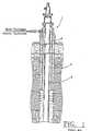
- FIG. 1the prior art is shown which demonstrates that at least in most cases 80-100% of the drilling operation must be completed before attempting to inject drill cuttings via the well head 1 into the annulus 3 located between the production or intermediate casing 5 and the surface casing string 7.
- the production string 5 and the surface casing string 7must be set by cementing them into the earth formation prior to injection of the drill cutting slurry. Therefore, all waste materials must be contained or disposed of during most of the drilling operation.
- cost soar for containing and transporting drilling waste materialit is therefore becoming imperative that new and improved methods for injecting cuttings back into the well being drilled.
- FIG. 1One such innovative method can be seen in FIG.
- a well head 12is modified to accommodate an injection tube 28 and connection 26, in addition to a drive or conductor casing string 14 and a surface casing string 16, the drive casing 14 passing through a body of water 18 and into the seabed earth formation 20.
- a production or intermediate casing 22is centrally located within the surface casing 16.
Landscapes
- Engineering & Computer Science (AREA)
- Mining & Mineral Resources (AREA)
- Geology (AREA)
- Environmental & Geological Engineering (AREA)
- Life Sciences & Earth Sciences (AREA)
- Geochemistry & Mineralogy (AREA)
- Physics & Mathematics (AREA)
- General Life Sciences & Earth Sciences (AREA)
- Fluid Mechanics (AREA)
- Earth Drilling (AREA)
- Consolidation Of Soil By Introduction Of Solidifying Substances Into Soil (AREA)
- Processing Of Solid Wastes (AREA)
- Catching Or Destruction (AREA)
- Perforating, Stamping-Out Or Severing By Means Other Than Cutting (AREA)
- Drilling And Boring (AREA)
Description
Claims (3)
- A method of injecting oil and gas well drill cuttings, produced from a wellbeing drilled, back into the earth formation (20) adjacent the well beingdrilled comprising the steps of:a) modifying a well casing head (12) to accommodate an injectiontube (28) having an external connection port, said casing head (12)being capable of accommodating at least a drive casing (14), and asurface casing (16);b) driving said drive casing (14) into an earth formation (20);c) installing said well casing head (12) on said drive casing (14);characterized in that said method further comprises the steps of:d) extending an injection tube (28), into a well being drilled into saidearth formation (20), between said drive casing (14) and saidsurface casing (16) in a progressive manner parallel to andcooperative with each length of said surface casing (16);e) securing said injection tube (28) to said surface casing (16) andsaid well head (12);f) cementing the formation (20) around at least a portion of saidsurface casing (16) and said injection tube (28); andg) perforating at least a portion of said injection tube (28) and saidcementing (32); and injecting a well cuttings slurry, removed whiledrilling said earth formation (20), into said injection tube (28) and into said earth formation (20) via said perforated portion of saidinjection tube (28) and cementing (32).
- The method of Claim 1 wherein the step of securing the injection tube(28) to the surface casing (16) comprises attaching the injection tube (28)to the surface casing with straps (30) along a length of the surface casing(16).
- The method of Claim 1 further comprising the step of disposing spacers(34) about the surface casing (16) to protect the injection tube (28).
Applications Claiming Priority (3)
| Application Number | Priority Date | Filing Date | Title |
|---|---|---|---|
| US08/904,797US5884715A (en) | 1997-08-01 | 1997-08-01 | Method and apparatus for injecting drilling waste into a well while drilling |
| US904797 | 1997-08-01 | ||
| PCT/US1998/004067WO1999006668A1 (en) | 1997-08-01 | 1998-03-03 | A method of injecting drilling waste into a well while drilling |
Publications (3)
| Publication Number | Publication Date |
|---|---|
| EP1000219A1 EP1000219A1 (en) | 2000-05-17 |
| EP1000219A4 EP1000219A4 (en) | 2000-06-28 |
| EP1000219B1true EP1000219B1 (en) | 2003-09-03 |
Family
ID=25419802
Family Applications (1)
| Application Number | Title | Priority Date | Filing Date |
|---|---|---|---|
| EP98908861AExpired - LifetimeEP1000219B1 (en) | 1997-08-01 | 1998-03-03 | A method of injecting drilling waste into a well while drilling |
Country Status (9)
| Country | Link |
|---|---|
| US (1) | US5884715A (en) |
| EP (1) | EP1000219B1 (en) |
| JP (1) | JP2001512203A (en) |
| AU (1) | AU734687B2 (en) |
| CA (1) | CA2294483C (en) |
| GB (1) | GB2327958B (en) |
| NO (1) | NO317126B1 (en) |
| NZ (1) | NZ503105A (en) |
| WO (1) | WO1999006668A1 (en) |
Families Citing this family (23)
| Publication number | Priority date | Publication date | Assignee | Title |
|---|---|---|---|---|
| NO310839B1 (en)* | 1998-09-18 | 2001-09-03 | Shore Tec As | Device for equipment adapted for use in the injection of waste products, for example drill cuttings or other toxic substances |
| US6394194B1 (en)* | 1999-04-26 | 2002-05-28 | Abb Vetco Gray Inc. | Method and apparatus for a drill cutting injection system |
| US6357968B1 (en)* | 2000-01-12 | 2002-03-19 | Sandia Corporation | Method and apparatus for constructing an underground barrier wall structure |
| US6484807B2 (en)* | 2000-11-29 | 2002-11-26 | Cooper Cameron Corporation | Wellhead assembly for injecting a fluid into a well and method of using the same |
| US6494267B2 (en) | 2000-11-29 | 2002-12-17 | Cooper Cameron Corporation | Wellhead assembly for accessing an annulus in a well and a method for its use |
| US6516861B2 (en) | 2000-11-29 | 2003-02-11 | Cooper Cameron Corporation | Method and apparatus for injecting a fluid into a well |
| US6659183B2 (en) | 2001-02-22 | 2003-12-09 | Abb Vetco Gray Inc. | Cuttings injection target plate |
| US20020117305A1 (en)* | 2001-02-23 | 2002-08-29 | Calder Ian Douglas | Cuttings injection and annulus remediation systems for wellheads |
| GB2414756B (en)* | 2001-07-12 | 2006-05-10 | Sensor Highway Ltd | Method and apparatus to monitor, control and log subsea wells |
| GB0121353D0 (en)* | 2001-09-04 | 2001-10-24 | Rig Technology Ltd | Improvements in or relating to transport of waste materials |
| BR0214464B1 (en)* | 2001-11-27 | 2012-07-10 | subsea wellhead assembly, cutout injection subsea wellhead assembly and method for communicating with the annular space of the wellhead assembly. | |
| US7493969B2 (en)* | 2003-03-19 | 2009-02-24 | Varco I/P, Inc. | Drill cuttings conveyance systems and methods |
| GB2414999B (en) | 2003-03-19 | 2006-10-25 | Varco Int | Apparatus and method for moving drilled cuttings |
| US6936092B2 (en)* | 2003-03-19 | 2005-08-30 | Varco I/P, Inc. | Positive pressure drilled cuttings movement systems and methods |
| US20100108319A1 (en)* | 2008-10-31 | 2010-05-06 | Baker Hughes Incorporated | Reduced Waste Cleaning Methods for Oil Well Related Systems |
| GB2465168B (en)* | 2008-11-07 | 2012-08-08 | Vetco Gray Controls Ltd | Disposal of well control fluids |
| GB2467322A (en) | 2009-01-29 | 2010-08-04 | Vetco Gray Controls Ltd | Well pump using supplied hydraulic fluid to pump accumulated control fluid into a production flowline |
| EP2628891A4 (en)* | 2010-10-12 | 2014-08-27 | Shijiazhuang Zhongmei Coal Mine Equipment Manufacture Co Ltd | Assembled drilling tool |
| CA2814750A1 (en)* | 2010-10-20 | 2012-04-26 | Exxonmobil Upstream Research Company | Methods for establishing a subsurface fracture network |
| ES2767448T3 (en)* | 2011-06-29 | 2020-06-17 | Grand Abyss Llc | Abyssal sequestration of nuclear waste and other types of hazardous waste |
| US9513398B2 (en)* | 2013-11-18 | 2016-12-06 | Halliburton Energy Services, Inc. | Casing mounted EM transducers having a soft magnetic layer |
| JP6622502B2 (en)* | 2015-07-30 | 2019-12-18 | 東洋建設株式会社 | Subsurface groundwater suction device, method for reducing the volume of mud and sludge in the bottom, methane hydrate recovery device and method in seabed |
| FR3053519B1 (en)* | 2016-06-30 | 2018-08-10 | Agence Nationale Pour La Gestion Des Dechets Radioactifs | METHOD FOR FORMING AND INSTALLING IN SITU A DOUBLE TUBING OF A SUBTERRANEAN RADIOACTIVE WASTE STORAGE ALVEOLE |
Family Cites Families (8)
| Publication number | Priority date | Publication date | Assignee | Title |
|---|---|---|---|---|
| US3347319A (en)* | 1965-03-15 | 1967-10-17 | Fenix & Scisson Inc | Large diameter casing |
| US4942929A (en)* | 1989-03-13 | 1990-07-24 | Atlantic Richfield Company | Disposal and reclamation of drilling wastes |
| GB8925075D0 (en)* | 1989-11-07 | 1989-12-28 | British Petroleum Co Plc | Sub-sea well injection system |
| US5129469A (en)* | 1990-08-17 | 1992-07-14 | Atlantic Richfield Company | Drill cuttings disposal method and system |
| US5109933A (en)* | 1990-08-17 | 1992-05-05 | Atlantic Richfield Company | Drill cuttings disposal method and system |
| WO1995014543A1 (en)* | 1993-11-29 | 1995-06-01 | Mobil Oil Corporation | A method for disposing of drilling wastes |
| US5613242A (en)* | 1994-12-06 | 1997-03-18 | Oddo; John E. | Method and system for disposing of radioactive solid waste |
| US5662169A (en)* | 1996-05-02 | 1997-09-02 | Abb Vetco Gray Inc. | Cuttings injection wellhead system |
- 1997
- 1997-08-01USUS08/904,797patent/US5884715A/ennot_activeExpired - Lifetime
- 1998
- 1998-02-11GBGB9802853Apatent/GB2327958B/ennot_activeExpired - Lifetime
- 1998-03-03AUAU66789/98Apatent/AU734687B2/ennot_activeCeased
- 1998-03-03JPJP2000505399Apatent/JP2001512203A/enactivePending
- 1998-03-03WOPCT/US1998/004067patent/WO1999006668A1/enactiveIP Right Grant
- 1998-03-03NZNZ503105Apatent/NZ503105A/enunknown
- 1998-03-03EPEP98908861Apatent/EP1000219B1/ennot_activeExpired - Lifetime
- 1998-03-03CACA002294483Apatent/CA2294483C/ennot_activeExpired - Fee Related
- 2000
- 2000-01-12NONO20000159Apatent/NO317126B1/ennot_activeIP Right Cessation
Also Published As
| Publication number | Publication date |
|---|---|
| GB9802853D0 (en) | 1998-04-08 |
| NO20000159L (en) | 2000-03-29 |
| JP2001512203A (en) | 2001-08-21 |
| EP1000219A4 (en) | 2000-06-28 |
| AU6678998A (en) | 1999-02-22 |
| WO1999006668A1 (en) | 1999-02-11 |
| NO20000159D0 (en) | 2000-01-12 |
| NO317126B1 (en) | 2004-08-23 |
| CA2294483C (en) | 2004-05-18 |
| EP1000219A1 (en) | 2000-05-17 |
| GB2327958B (en) | 2000-08-23 |
| AU734687B2 (en) | 2001-06-21 |
| CA2294483A1 (en) | 1999-02-11 |
| NZ503105A (en) | 2001-08-31 |
| GB2327958A (en) | 1999-02-10 |
| US5884715A (en) | 1999-03-23 |
Similar Documents
| Publication | Publication Date | Title |
|---|---|---|
| EP1000219B1 (en) | A method of injecting drilling waste into a well while drilling | |
| US6516861B2 (en) | Method and apparatus for injecting a fluid into a well | |
| US8403062B2 (en) | Wellbore method and apparatus for completion, production and injection | |
| US6772837B2 (en) | Screen assembly having diverter members and method for progressively treating an interval of a welibore | |
| US20030075326A1 (en) | Well completion method | |
| ITMI952418A1 (en) | METHOD FOR UNDERGROUND EXCLUSION OF FLUIDS | |
| US6494267B2 (en) | Wellhead assembly for accessing an annulus in a well and a method for its use | |
| EP1217166B1 (en) | Method and apparatus for drilling and completing a well | |
| CA2511249C (en) | Method for drilling a lateral wellbore with secondary fluid injection | |
| RU2291284C2 (en) | Method for construction and completion of force wells | |
| CN101395337A (en) | Method and apparatus for selectively treating perforated casing | |
| WO1994017280A1 (en) | Formation compatible fluid gravel packing method | |
| US6793017B2 (en) | Method and apparatus for transferring material in a wellbore | |
| US20250154860A1 (en) | Downhole processing and disposal of produced solids from a well | |
| US5474127A (en) | Annular safety system for oil well | |
| WO2012015528A1 (en) | Enhanced hydrocarbon fluid recovery via formation collapse | |
| US4759408A (en) | Method of shutting off a portion of a producing zone in a hydrocarbon producing well | |
| WO1995014543A1 (en) | A method for disposing of drilling wastes | |
| Eide et al. | Further advances in coiled-tubing drilling | |
| Juiniti et al. | Campos Basin: Lessons learned and critical issues to be overcome in drilling and completion operations | |
| MXPA00001095A (en) | A method of injecting drilling waste into a well while drilling | |
| Kunze et al. | Merits of Suspending the First Platform Well as a Cuttings Injector | |
| US12371967B2 (en) | Wellbore operations system and method | |
| Goranson | Applicability of petroleum horizontal drilling technology to hazardous waste site characterization and remediation | |
| Anchliya et al. | Monodiameter drilling: review, case study, current status and challenges ahead |
Legal Events
| Date | Code | Title | Description |
|---|---|---|---|
| PUAI | Public reference made under article 153(3) epc to a published international application that has entered the european phase | Free format text:ORIGINAL CODE: 0009012 | |
| 17P | Request for examination filed | Effective date:20000110 | |
| AK | Designated contracting states | Kind code of ref document:A1 Designated state(s):BE DK ES FI FR IE IT NL PT SE | |
| A4 | Supplementary search report drawn up and despatched | Effective date:20000516 | |
| AK | Designated contracting states | Kind code of ref document:A4 Designated state(s):BE DK ES FI FR IE IT NL PT SE | |
| 17Q | First examination report despatched | Effective date:20010125 | |
| GRAH | Despatch of communication of intention to grant a patent | Free format text:ORIGINAL CODE: EPIDOS IGRA | |
| RAP1 | Party data changed (applicant data changed or rights of an application transferred) | Owner name:BAKER HUGHES INCORPORATED | |
| RIN1 | Information on inventor provided before grant (corrected) | Inventor name:REDDOCH, JEFFREY | |
| GRAS | Grant fee paid | Free format text:ORIGINAL CODE: EPIDOSNIGR3 | |
| GRAA | (expected) grant | Free format text:ORIGINAL CODE: 0009210 | |
| AK | Designated contracting states | Kind code of ref document:B1 Designated state(s):BE DK ES FI FR IE IT NL PT SE | |
| PG25 | Lapsed in a contracting state [announced via postgrant information from national office to epo] | Ref country code:NL Free format text:LAPSE BECAUSE OF FAILURE TO SUBMIT A TRANSLATION OF THE DESCRIPTION OR TO PAY THE FEE WITHIN THE PRESCRIBED TIME-LIMIT Effective date:20030903 Ref country code:FR Free format text:LAPSE BECAUSE OF FAILURE TO SUBMIT A TRANSLATION OF THE DESCRIPTION OR TO PAY THE FEE WITHIN THE PRESCRIBED TIME-LIMIT Effective date:20030903 Ref country code:FI Free format text:LAPSE BECAUSE OF FAILURE TO SUBMIT A TRANSLATION OF THE DESCRIPTION OR TO PAY THE FEE WITHIN THE PRESCRIBED TIME-LIMIT Effective date:20030903 Ref country code:BE Free format text:LAPSE BECAUSE OF FAILURE TO SUBMIT A TRANSLATION OF THE DESCRIPTION OR TO PAY THE FEE WITHIN THE PRESCRIBED TIME-LIMIT Effective date:20030903 | |
| REG | Reference to a national code | Ref country code:IE Ref legal event code:FG4D | |
| PG25 | Lapsed in a contracting state [announced via postgrant information from national office to epo] | Ref country code:SE Free format text:LAPSE BECAUSE OF FAILURE TO SUBMIT A TRANSLATION OF THE DESCRIPTION OR TO PAY THE FEE WITHIN THE PRESCRIBED TIME-LIMIT Effective date:20031203 Ref country code:DK Free format text:LAPSE BECAUSE OF FAILURE TO SUBMIT A TRANSLATION OF THE DESCRIPTION OR TO PAY THE FEE WITHIN THE PRESCRIBED TIME-LIMIT Effective date:20031203 | |
| PG25 | Lapsed in a contracting state [announced via postgrant information from national office to epo] | Ref country code:ES Free format text:LAPSE BECAUSE OF FAILURE TO SUBMIT A TRANSLATION OF THE DESCRIPTION OR TO PAY THE FEE WITHIN THE PRESCRIBED TIME-LIMIT Effective date:20031214 | |
| NLV1 | Nl: lapsed or annulled due to failure to fulfill the requirements of art. 29p and 29m of the patents act | ||
| PG25 | Lapsed in a contracting state [announced via postgrant information from national office to epo] | Ref country code:PT Free format text:LAPSE BECAUSE OF FAILURE TO SUBMIT A TRANSLATION OF THE DESCRIPTION OR TO PAY THE FEE WITHIN THE PRESCRIBED TIME-LIMIT Effective date:20040203 | |
| PG25 | Lapsed in a contracting state [announced via postgrant information from national office to epo] | Ref country code:IE Free format text:LAPSE BECAUSE OF NON-PAYMENT OF DUE FEES Effective date:20040303 | |
| PLBE | No opposition filed within time limit | Free format text:ORIGINAL CODE: 0009261 | |
| STAA | Information on the status of an ep patent application or granted ep patent | Free format text:STATUS: NO OPPOSITION FILED WITHIN TIME LIMIT | |
| 26N | No opposition filed | Effective date:20040604 | |
| EN | Fr: translation not filed | ||
| REG | Reference to a national code | Ref country code:IE Ref legal event code:MM4A | |
| PGFP | Annual fee paid to national office [announced via postgrant information from national office to epo] | Ref country code:IT Payment date:20170320 Year of fee payment:20 |