EP0996390B1 - Flow-around valve - Google Patents
Flow-around valveDownload PDFInfo
- Publication number
- EP0996390B1 EP0996390B1EP98933342AEP98933342AEP0996390B1EP 0996390 B1EP0996390 B1EP 0996390B1EP 98933342 AEP98933342 AEP 98933342AEP 98933342 AEP98933342 AEP 98933342AEP 0996390 B1EP0996390 B1EP 0996390B1
- Authority
- EP
- European Patent Office
- Prior art keywords
- balloon
- valve
- urethral
- urethra
- bladder
- Prior art date
- Legal status (The legal status is an assumption and is not a legal conclusion. Google has not performed a legal analysis and makes no representation as to the accuracy of the status listed.)
- Expired - Lifetime
Links
- 210000003708urethraAnatomy0.000claimsdescription46
- 210000002700urineAnatomy0.000claimsdescription36
- 206010046479Urethral valvesDiseases0.000claimsdescription32
- 239000000126substanceSubstances0.000claimsdescription7
- 238000004873anchoringMethods0.000claimsdescription5
- 241000894006BacteriaSpecies0.000description12
- 239000012528membraneSubstances0.000description12
- 230000027939micturitionEffects0.000description11
- XLYOFNOQVPJJNP-UHFFFAOYSA-NwaterSubstancesOXLYOFNOQVPJJNP-UHFFFAOYSA-N0.000description6
- 238000003780insertionMethods0.000description4
- 230000037431insertionEffects0.000description4
- 206010021639IncontinenceDiseases0.000description2
- 230000000844anti-bacterial effectEffects0.000description2
- 239000011248coating agentSubstances0.000description2
- 238000000576coating methodMethods0.000description2
- 208000015181infectious diseaseDiseases0.000description2
- 230000033001locomotionEffects0.000description2
- 230000005012migrationEffects0.000description2
- 238000013508migrationMethods0.000description2
- 238000012986modificationMethods0.000description2
- 230000004048modificationEffects0.000description2
- 0*CC(*=C)N=OChemical compound*CC(*=C)N=O0.000description1
- GDOPTJXRTPNYNR-UHFFFAOYSA-NCC1CCCC1Chemical compoundCC1CCCC1GDOPTJXRTPNYNR-UHFFFAOYSA-N0.000description1
- 230000001580bacterial effectEffects0.000description1
- 230000000903blocking effectEffects0.000description1
- 239000013505freshwaterSubstances0.000description1
- 230000007794irritationEffects0.000description1
- 239000007788liquidSubstances0.000description1
- 239000000463materialSubstances0.000description1
- 231100000344non-irritatingToxicity0.000description1
- 229910052710siliconInorganic materials0.000description1
- 239000010703siliconSubstances0.000description1
Images


Classifications
- A—HUMAN NECESSITIES
- A61—MEDICAL OR VETERINARY SCIENCE; HYGIENE
- A61F—FILTERS IMPLANTABLE INTO BLOOD VESSELS; PROSTHESES; DEVICES PROVIDING PATENCY TO, OR PREVENTING COLLAPSING OF, TUBULAR STRUCTURES OF THE BODY, e.g. STENTS; ORTHOPAEDIC, NURSING OR CONTRACEPTIVE DEVICES; FOMENTATION; TREATMENT OR PROTECTION OF EYES OR EARS; BANDAGES, DRESSINGS OR ABSORBENT PADS; FIRST-AID KITS
- A61F2/00—Filters implantable into blood vessels; Prostheses, i.e. artificial substitutes or replacements for parts of the body; Appliances for connecting them with the body; Devices providing patency to, or preventing collapsing of, tubular structures of the body, e.g. stents
- A61F2/0004—Closure means for urethra or rectum, i.e. anti-incontinence devices or support slings against pelvic prolapse
- A61F2/0022—Closure means for urethra or rectum, i.e. anti-incontinence devices or support slings against pelvic prolapse placed deep in the body opening
- A61F2/0027—Closure means for urethra or rectum, i.e. anti-incontinence devices or support slings against pelvic prolapse placed deep in the body opening inflatable
- A—HUMAN NECESSITIES
- A61—MEDICAL OR VETERINARY SCIENCE; HYGIENE
- A61M—DEVICES FOR INTRODUCING MEDIA INTO, OR ONTO, THE BODY; DEVICES FOR TRANSDUCING BODY MEDIA OR FOR TAKING MEDIA FROM THE BODY; DEVICES FOR PRODUCING OR ENDING SLEEP OR STUPOR
- A61M25/00—Catheters; Hollow probes
- A61M25/0067—Catheters; Hollow probes characterised by the distal end, e.g. tips
- A61M25/0074—Dynamic characteristics of the catheter tip, e.g. openable, closable, expandable or deformable
- A61M25/0075—Valve means
- Y—GENERAL TAGGING OF NEW TECHNOLOGICAL DEVELOPMENTS; GENERAL TAGGING OF CROSS-SECTIONAL TECHNOLOGIES SPANNING OVER SEVERAL SECTIONS OF THE IPC; TECHNICAL SUBJECTS COVERED BY FORMER USPC CROSS-REFERENCE ART COLLECTIONS [XRACs] AND DIGESTS
- Y10—TECHNICAL SUBJECTS COVERED BY FORMER USPC
- Y10S—TECHNICAL SUBJECTS COVERED BY FORMER USPC CROSS-REFERENCE ART COLLECTIONS [XRACs] AND DIGESTS
- Y10S128/00—Surgery
- Y10S128/25—Artificial sphincters and devices for controlling urinary incontinence
Definitions
- This inventionrelates generally to devices that control incontinence and, more particularly, to urethral valves.
- Incontinenceis a serious problem for many people and, in particular, for many females.
- Adult diapersmay be used to capture leaking urine, or alternatively, urethral plugs or valves may be used to provide continence.
- Urethral plugs and valuesare positioned in the urethra to block urine flow. The plug is removed from the urethra for urination. The valve remains in place and opens to allow urine to flow through the valve, and out of the body.
- the urethral plugis used once and then thrown away. After voiding, a new plug must be inserted to again provide continence. Over time, with the repeated insertion and removal of the plugs, the lining of the urethra may become irritated.
- a plugEach time a plug is inserted, it carries bacteria from the meatus and the distal end of the urethra into the proximal end of the urethra.
- the bacteriamay infect the urethra, particularly if the lining is irritated. Further, the bacteria may migrate up into and infect the bladder.
- the urethral valveremains in the urethra over some period of days.
- the typical valveextends through the urethra to the outside of the body, where a mechanism for opening the valve is accessible to the user.
- the valvethus provides a path for bacteria to travel from the meatus and the distal end of the urethra to the proximal end of the urethra and the bladder. Further, the insertion of the valve into the urethra often irritates the lining of the urethra, and thus, promotes bacterial growth.
- An improved urethral valve systemincludes a valve balloon that inflates to provide continence and in certain embodiments deflates to allow urine to flow around the balloon.
- a small-diameter catheteris attached to the balloon and extends through the urethra to provide access to the balloon from outside the body.
- the urineflows around the balloon, the urine also flows around the catheter and through the urethra, and out of the body through the meatus. The urine cleanses the valve balloon, catheter and the urethra of bacteria, and thus, minimizes infection.
- the valve systemmay be anchored in the bladder, to prevent the system from being drawn from the body by the flow of urine.
- the anchormay be, for example, a balloon, which may be either the same balloon that provides continence or a second balloon. If a single balloon is used both to anchor the system and provide continence, the balloon may deflate to a shape that retains the balloon in the bladder against the flow of urine.
- the systemmay include a mechanical means to hold the deflated balloon in the bladder, such as, for example, rubber fingers that extend from the base of the balloon beyond the neck of the bladder.
- the valve balloonmay instead be positioned within the urethra, with an anchoring mechanism positioned in the bladder to hold the deflated valve balloon in place during urination.
- the catheterruns from the valve balloon through the urethra to the outside of the body, and includes a check valve at the end that is accessible to the user.
- a small pumpthat supplies air or a liquid such as water to inflate the balloon.
- the usermanipulates the check valve to allow the water or air to drain from the balloon.
- the catheterhas a small diameter, since urine flows around the catheter and not through it.
- the valve systempreferably includes an everting mechanism that provides non-irritating delivery of the valve and/or anchoring balloons to the body.
- An everted membraneunrolls to provide a path through the urethra for the balloons, to prevent irritation of the lining of the urethra.
- the everting mechanismalso prevents bacteria from being drawn from the meatus and distal end of the urethra into the proximal end of the urethra and into the bladder.
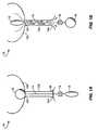
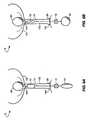
- a urethral valve system 10includes a valve balloon 12 that is positioned in a bladder 100 to obstruct the flow of urine from the bladder.
- the diameter of the balloon 12must be large enough essentially to seal the neck 101 of the bladder 100 and prevent urine flow from the bladder.
- a small-diameter catheter 14attaches to the balloon 12 and extends through the urethra 102 and past the meatus 104.
- a pump 18, which is removably attached to the check valve 16,provides, for example, the water to the system. When the balloon is inflated, as depicted in Fig. 1A, the balloon provides continence.
- a userdeflates the balloon 12 through the check valve 16.
- urineflows around the balloon, through the neck 101 of the bladder 100, through the urethra 102 and around catheter 14, and out of the meatus 104.
- the urine flowcleanses the balloon 12 and the catheter 14 of bacteria in the same way that the body naturally cleanses the urethra, and thus minimizes the chances for infection from upwardly migrating bacteria.
- the balloon 12 and the catheter 14may also be coated with an antibacterial coating, to prevent colonization.
- the pump 18captures the water and retains it for use in re-inflating the balloon 12.
- the usermay instead release the water from the system 10, and use fresh water to re-inflate the balloon.
- the balloonis deflated for insertion into and removal from the bladder. Once deflated, the balloon is removed by gently pulling on the catheter 14.
- a meatal collar 20may be positioned slightly above the check valve 16. Further, the meatal collar 20, like the other system components, may be coated with an anti-bacterial coating to prevent colonization.
- the balloon 12 and the catheter 14may be made of any inflatable, non-reactive material, such as silicon.
- the catheter 14has a small diameter since urine flows around the catheter rather than through the catheter.
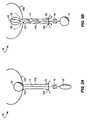
- Figs 2A and 2Bdepict a second embodiment of the urethral valve system.
- the valve balloon 12is attached to a second, fixation balloon 22, which is included in the system to anchor it within the bladder 100.
- the fixation balloon in its inflated statehas a diameter that is larger than the neck 101 of the bladder 100, to ensure that the system will not be pulled from the bladder by the flow of urine.
- the fixation balloon 22includes a channel 24 that houses the valve balloon 12.
- the valve balloonmay be attached to the fixation balloon by, for example, webbing (not shown) through which urine can readily flow.
- the channel 24When the valve balloon 12 is inflated, the channel 24 is sealed to provide continence. When the valve balloon is deflated, as depicted in Fig. 2B, the channel 24 is opened and urine flows through the channel and around the valve balloon 12. The fixation balloon remains inflated during urination and holds the system in position against the flow of urine. As discussed above, the urine flow cleanses bacteria from the balloon 12 and the catheter 14, which comes in contact with the meatus 104 and the distal end of the urethra. The cleansing minimizes the upward migration of bacteria.
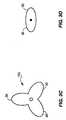
- Figs. 3A-3Ddepict a third embodiment of the urethral valve system.
- the valve balloon 12acts also as the anchoring mechanism. There is thus no need for the fixation balloon 22 (Fig. 2A).
- the valve balloon 12deflates into a shape 12b or 12c that includes one or more elongated arms 30. Urine can then flow around the arms 30, through the neck 101 of the bladder 100, around the catheter 14 and through the urethra 102, and out of the meatus 104.
- the arms 30have a span that is longer than the width of the neck 101 of the bladder 100, and they thus, retain the balloon 12 in the bladder against urine flow.
- the arms 30are also flexible so that the balloon can be removed from the bladder by gently pulling on the catheter 14.
- a fourth embodiment of the urethral valve systemincludes flexible fixation tabs 40 that extend outwardly from a base 42 of the balloon 12.
- the tabs 40hold the balloon in place at the neck 101 of the bladder 100. Urine then flows around the balloon and the tabs, out of the bladder, around the catheter 14 and through the urethra, and out of the body through the meatus.
- the catheter 14is stiffened somewhat, so that a user can move the valve balloon 12 away from the neck 101 of the bladder. Urine can then flow out of the neck of the bladder 100 and through the urethra 102. To reposition the valve balloon 12 in the neck of the bladder the user then gently pulls on the catheter 14.
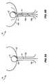
- the valve balloonmay be positioned in the urethra 102.
- the valve balloon 12When the valve balloon 12 is inflated, it provides continence by blocking the flow of urine in the urethra.
- the balloon 12When the balloon 12 is deflated, urine flows around the balloon and the attached catheter 14 and through the distal end of the urethra 102 and out of the body through the meatus 104.
- a second balloon 60may be positioned in the bladder, as shown in Fig. 6.
- foldable arms 70which are inserted and then unfolded in the bladder 100, may be used to anchor the system.
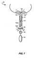
- Fig. 8depicts an everting mechanism 80 that may be used for introduction of the valve system 10 (Figs. 1-7) into the body through the urethra.
- the everting mechanism 80includes an introducing device 82, such as, for example, a tube, that a user inserts into the distal end of the urethra 102 up to a stop 81.
- the tubecontains an everted membrane 84 with one end held by the stop.
- the membrane 84unrolls, as depicted by dotted lines, as an advancing device 86 is pushed deeper into the urethra.
- the unrolled membranethen provides a path through which the valve system may be inserted, without coming into contact with the lining of the urethra. After the system is fully inserted, the membrane 84 is removed from the body.
- the surface of the membrane that comes in contact with the lining of the urethradoes not come in contact with the distal end of the urethra. Accordingly, bacteria from the distal end of the urethra is not carried deeper into the urethra or into the bladder by either the membrane, or the valve system that is introduced through the membrane.
Landscapes
- Health & Medical Sciences (AREA)
- Urology & Nephrology (AREA)
- Cardiology (AREA)
- Oral & Maxillofacial Surgery (AREA)
- Transplantation (AREA)
- Engineering & Computer Science (AREA)
- Biomedical Technology (AREA)
- Heart & Thoracic Surgery (AREA)
- Vascular Medicine (AREA)
- Life Sciences & Earth Sciences (AREA)
- Animal Behavior & Ethology (AREA)
- General Health & Medical Sciences (AREA)
- Public Health (AREA)
- Veterinary Medicine (AREA)
- External Artificial Organs (AREA)
- Prostheses (AREA)
Description
Claims (11)
- A urethral valve system (10) insertable into abody of a user for controlling urine flow from abladder (100) through a urethra (102), the valvesystem comprising:characterised by the valve system being adaptedto remain inserted in the body when the valve balloonis deflated to allow urine to flow around thevalve balloon and through the urethra while the valveballoon is deflated.a valve balloon (12) adapted to be inflatable toprevent urine flow; andat catheter (14) having a first end connected tothe valve balloon and operable in use to extendthrough the urethra to provide access to the valveballoon from outside of the body for inflation anddeflation of the valve balloon;
- The urethral valve system of claim 1 wherein thevalve balloon is adapted to be positioned within thebladder.
- The urethral valve system of claim 2 furtherincluding a fixation balloon (22) that is operable to hold the valve system in place against urine flow, thefixation balloon including an interior channel (24)that houses the valve balloon.
- The urethral valve system of claim 2 wherein thevalve balloon when deflated has a shape adapted tohold the valve balloon in the bladder against urineflow.
- The urethral valve system of claim 2 furtherincluding a flexible anchoring mechanism (30,40)adapted to hold the deflated valve balloon in thebladder against urine flow.
- The urethral valve system of claim 5 wherein theanchoring mechanism includes one or more flexiblefingers (40) adapted to extend from a base of thevalve balloon along the interior of the bladder.
- The urethral valve system of claim 1 furtherincluding a check valve (16) at a second end of thecatheter, the check valve being operable to open toallow a substance to be inserted into the valveballoon in order to inflate the valve balloon andoperable to close to contain the substance, the check valve being operable to reopen to release thesubstance contained in the valve balloon in order todeflate the valve balloon.
- The urethral valve system of claim 1, wherein thevalve balloon is adapted to be positioned within theurethra, and the valve system further includes afixation balloon (22), the fixation balloon beingadapted to be positioned within the bladder to holdthe valve balloon in place against urine flow.
- The urethral valve system of claim 8 furtherincluding a check valve (16) at a second end of thecatheter, the check valve being operable to open toallow a substance to be inserted into the valveballoon in order to inflate the valve balloon andoperable to close to contain the substance to keep thevalve balloon inflated, the check valve being operableto reopen to release the substance contained in thevalve balloon in order to deflate the balloon.
- The urethral valve system of claim 1 wherein thecatheter is positionable such that when urine flowsaround the balloon, the urine flows around thecatheter.
- The urethral valve of claim 1, furthercomprising:an everting mechanism (84) adapted for insertingthe balloon and the catheter into the body through theurethra when the balloon is in the deflated state.
Applications Claiming Priority (3)
| Application Number | Priority Date | Filing Date | Title |
|---|---|---|---|
| US896072 | 1992-06-02 | ||
| US08/896,072US6042535A (en) | 1997-07-17 | 1997-07-17 | Flow-around valve |
| PCT/US1998/014577WO1999003423A1 (en) | 1997-07-17 | 1998-07-15 | Flow-around valve |
Publications (2)
| Publication Number | Publication Date |
|---|---|
| EP0996390A1 EP0996390A1 (en) | 2000-05-03 |
| EP0996390B1true EP0996390B1 (en) | 2005-03-16 |
Family
ID=25405582
Family Applications (1)
| Application Number | Title | Priority Date | Filing Date |
|---|---|---|---|
| EP98933342AExpired - LifetimeEP0996390B1 (en) | 1997-07-17 | 1998-07-15 | Flow-around valve |
Country Status (6)
| Country | Link |
|---|---|
| US (2) | US6042535A (en) |
| EP (1) | EP0996390B1 (en) |
| JP (1) | JP4074429B2 (en) |
| AU (1) | AU8300498A (en) |
| DE (1) | DE69829376T8 (en) |
| WO (1) | WO1999003423A1 (en) |
Families Citing this family (38)
| Publication number | Priority date | Publication date | Assignee | Title |
|---|---|---|---|---|
| US6293923B1 (en)* | 1999-03-15 | 2001-09-25 | Innoventions, Inc. | Intravesicular balloon |
| USD446580S1 (en) | 1999-11-02 | 2001-08-14 | Hector D. Allende | Anorectal apparatus |
| US6551304B1 (en)* | 1999-12-01 | 2003-04-22 | Abbeymoor Medical, Inc. | Magnetic retrieval device and method of use |
| US6527702B2 (en)* | 2000-02-01 | 2003-03-04 | Abbeymoor Medical, Inc. | Urinary flow control device and method |
| US10327880B2 (en) | 2000-04-14 | 2019-06-25 | Attenuex Technologies, Inc. | Attenuation device for use in an anatomical structure |
| US7374532B2 (en) | 2000-04-14 | 2008-05-20 | Attenuex Technologies, Inc. | High vapor pressure attenuation device |
| US6682473B1 (en)* | 2000-04-14 | 2004-01-27 | Solace Therapeutics, Inc. | Devices and methods for attenuation of pressure waves in the body |
| US7470228B2 (en)* | 2000-04-14 | 2008-12-30 | Attenuex Technologies, Inc. | Method of treating benign hypertrophy of the prostate |
| US7141038B2 (en)* | 2000-08-07 | 2006-11-28 | Abbeymoor Medical, Inc. | Endourethral device and method |
| US6719709B2 (en)* | 2000-08-31 | 2004-04-13 | Abbeymoor Medical, Inc. | Diagnostic urethral assembly and method |
| GB0024355D0 (en) | 2000-10-05 | 2000-11-22 | Richardson Margeret P | Urinary catheters |
| ATE483492T1 (en)* | 2001-01-23 | 2010-10-15 | Abbeymoor Medical Inc | ENDOURETHRAL DEVICE |
| US6991596B2 (en)* | 2001-10-18 | 2006-01-31 | Abbeymoor Medical, Inc. | Endourethral device and method |
| US6949125B2 (en)* | 2002-04-16 | 2005-09-27 | Boston Scientific Scimed, Inc. | Ureteral stent with end-effector and related methods |
| US7608067B2 (en)* | 2002-11-06 | 2009-10-27 | Aram Bonni | Patient-adjustable incontinence device (AID) |
| JP4673305B2 (en)* | 2003-08-11 | 2011-04-20 | ウィルソン−クック・メディカル・インコーポレーテッド | Surgical graft |
| GB2407507B (en)* | 2003-10-29 | 2008-03-26 | Martin Lister | Artificial bladder |
| CA2558922A1 (en)* | 2004-03-23 | 2005-10-13 | Boston Scientific Limited | Agent eluting stent and catheter |
| WO2007038476A2 (en)* | 2005-09-26 | 2007-04-05 | Atteneux Technologies, Inc. | Pressure attenuation device |
| DE102008033002A1 (en)* | 2008-07-14 | 2010-01-21 | Markus Schedler | Device for producing urinary continence with reduced effect of female bladder closing muscles, has bladder anchor, urethra stab and supporting device, where urethra stab is formed such that device is disposed in urethra |
| WO2010068467A1 (en) | 2008-11-25 | 2010-06-17 | Attenuex Technologies, Inc. | Implant with high vapor pressure medium |
| CA3026550C (en)* | 2010-11-03 | 2020-11-10 | Coloplast A/S | Urological device comprising extending leaflet |
| US20130079589A1 (en)* | 2011-09-22 | 2013-03-28 | Coloplast A/S | Incontinence treatment device configured for urethral placement into the bladder |
| US8894563B2 (en) | 2012-08-10 | 2014-11-25 | Attenuex Technologies, Inc. | Methods and systems for performing a medical procedure |
| WO2015070095A1 (en)* | 2013-11-11 | 2015-05-14 | Cross Bay Medical, Inc. | Apparatus and methods for accessing and sealing bodily vessels and cavities |
| US10034986B2 (en) | 2013-11-11 | 2018-07-31 | Crossbay Medical, Inc. | Method and apparatus of tubal patency catheter and delivery systems |
| US9101391B2 (en) | 2013-11-11 | 2015-08-11 | Cross Bay Medical, Inc. | Apparatus and methods for accessing and sealing bodily vessels and cavities |
| US10245074B2 (en) | 2013-11-11 | 2019-04-02 | Crossbay Medical, Inc. | Apparatus and methods for accessing and sealing bodily vessels and cavities |
| WO2015187113A1 (en)* | 2014-06-04 | 2015-12-10 | Astra Medikal Tibbi Aletler Ith Ihr Tic Ltd Şti | Balloon unit serving as a valve found inside reservoir catheter |
| WO2015187112A1 (en)* | 2014-06-04 | 2015-12-10 | Astra Medikal Tibbi Aletler Ith Ihr Tic Ltd Şti | Autocontrolled, reservoir-balloon catether used in lower urninary systems with a balloon inside |
| JP6386858B2 (en)* | 2014-09-30 | 2018-09-05 | テルモ株式会社 | Medical long body insertion aid and medical long body set |
| US20220022916A1 (en)* | 2018-12-10 | 2022-01-27 | Alydia Health, Inc. | Postpartum uterine hemorrhage device |
| WO2020163625A1 (en) | 2019-02-07 | 2020-08-13 | Solace Therapeutics, Inc. | Pressure attenuation device |
| CA3160029A1 (en) | 2019-10-09 | 2021-04-15 | Steven R. Bacich | Apparatus and method for everting catheter for iud delivery and placement in the uterine cavity |
| CN111888065B (en)* | 2020-08-03 | 2021-07-02 | 吉林大学 | A nursing device for urinary tract intubation for adult patients in ICU ward |
| KR102588174B1 (en)* | 2021-08-17 | 2023-10-19 | 주식회사 케이아이플렉스 | Balloon urethral catheter |
| WO2025088218A1 (en)* | 2023-10-27 | 2025-05-01 | Nowwell Development AS | Urinary flow control device |
| CN119184942B (en)* | 2024-11-27 | 2025-03-07 | 张家港神港医疗用品有限公司 | Liquid draining structure of urine collecting bag |
Citations (4)
| Publication number | Priority date | Publication date | Assignee | Title |
|---|---|---|---|---|
| US3841304A (en)* | 1972-10-16 | 1974-10-15 | A Jones | Inflatable leakage inhibitor |
| US5088980A (en)* | 1990-05-31 | 1992-02-18 | The United States Of America As Represented By The Department Of Health And Human Services | Intra-urethral valve with integral spring |
| US5090424A (en)* | 1990-12-31 | 1992-02-25 | Uromed Corporation | Conformable urethral plug |
| US5513659A (en)* | 1994-10-24 | 1996-05-07 | Iotek, Inc. | Incontinence device |
Family Cites Families (24)
| Publication number | Priority date | Publication date | Assignee | Title |
|---|---|---|---|---|
| US2494393A (en)* | 1949-02-05 | 1950-01-10 | Otis F Lamson | Removable appliance for use as an artificial dam in cases of rectal incontinence |
| US3583391A (en)* | 1968-11-21 | 1971-06-08 | American Hospital Supply Corp | Medical instrument with outrolling catheter |
| US3630206A (en)* | 1970-01-02 | 1971-12-28 | Bruce Gingold | Bladder catheter |
| US3750194A (en)* | 1971-03-16 | 1973-08-07 | Fairchild Industries | Apparatus and method for reversibly closing a natural or implanted body passage |
| US3769981A (en)* | 1972-02-09 | 1973-11-06 | Kendall & Co | Urinary catheter |
| US3797478A (en)* | 1972-07-11 | 1974-03-19 | M Walsh | Multi-functional valve for use in the urethra |
| US3908635A (en)* | 1974-06-24 | 1975-09-30 | Nicholas F Viek | Simplified catheter |
| US4419985A (en)* | 1980-08-28 | 1983-12-13 | Medical Engineering Corporation | Apparatus for reversibly closing a body passage |
| US4386601A (en)* | 1981-08-12 | 1983-06-07 | Medical Engineering Corporation | Artificial sphincter |
| US4579554A (en)* | 1984-01-30 | 1986-04-01 | Glassman Jacob A | Indwelling urinary catheter |
| FR2595564A1 (en)* | 1986-03-11 | 1987-09-18 | Lavarenne Vincent | URETRAL ENDOPROTHESIS |
| US5112306A (en)* | 1986-03-25 | 1992-05-12 | American Medical Systems, Inc. | Method and apparatus for valving body fluids |
| DE3634569A1 (en)* | 1986-10-10 | 1988-04-21 | Sachse Hans E | CONDOM CATHETER, A URINE TUBE CATHETER FOR PREVENTING RISING INFECTIONS |
| DK546787A (en)* | 1986-10-20 | 1988-04-21 | Vance Products Inc | TRANSURETHRAL INCONTINENCE EQUIPMENT |
| US4994066A (en)* | 1988-10-07 | 1991-02-19 | Voss Gene A | Prostatic stent |
| US4932938A (en)* | 1989-05-05 | 1990-06-12 | Medical Engineering Corporation | Urethral indwelling catheter with incontinence control |
| US5030199A (en)* | 1989-12-11 | 1991-07-09 | Medical Engineering Corporation | Female incontinence control device with magnetically operable valve and method |
| US5114398A (en)* | 1990-02-27 | 1992-05-19 | Medical Engineering Corporation | Female incontinence control device with mechanically operable valve |
| US5306241A (en)* | 1990-08-16 | 1994-04-26 | Samples Charles R | Method of catheterization on and bladder drainage |
| US5096454A (en)* | 1990-08-16 | 1992-03-17 | Samples Charles R | Method of catheterization and bladder drainage |
| US5479945A (en)* | 1990-12-31 | 1996-01-02 | Uromed Corporation | Method and a removable device which can be used for the self-administered treatment of urinary tract infections or other disorders |
| DE4427443A1 (en)* | 1994-08-03 | 1996-02-08 | Sachse Hans E | Urethra catheter with holder in bladder |
| US5713861A (en)* | 1994-10-17 | 1998-02-03 | Vanarthos; William | Trauma urethral catheter and method of using same |
| US5701916A (en)* | 1995-08-16 | 1997-12-30 | Hk Medical Technologies Incorporated | Intraurethral bladder control device with retainer apparatus |
- 1997
- 1997-07-17USUS08/896,072patent/US6042535A/ennot_activeExpired - Lifetime
- 1998
- 1998-07-15WOPCT/US1998/014577patent/WO1999003423A1/enactiveIP Right Grant
- 1998-07-15DEDE69829376Tpatent/DE69829376T8/ennot_activeExpired - Fee Related
- 1998-07-15EPEP98933342Apatent/EP0996390B1/ennot_activeExpired - Lifetime
- 1998-07-15AUAU83004/98Apatent/AU8300498A/ennot_activeAbandoned
- 1998-07-15JPJP2000502730Apatent/JP4074429B2/ennot_activeExpired - Fee Related
- 1998-11-12USUS09/189,951patent/US6102848A/ennot_activeExpired - Lifetime
Patent Citations (4)
| Publication number | Priority date | Publication date | Assignee | Title |
|---|---|---|---|---|
| US3841304A (en)* | 1972-10-16 | 1974-10-15 | A Jones | Inflatable leakage inhibitor |
| US5088980A (en)* | 1990-05-31 | 1992-02-18 | The United States Of America As Represented By The Department Of Health And Human Services | Intra-urethral valve with integral spring |
| US5090424A (en)* | 1990-12-31 | 1992-02-25 | Uromed Corporation | Conformable urethral plug |
| US5513659A (en)* | 1994-10-24 | 1996-05-07 | Iotek, Inc. | Incontinence device |
Also Published As
| Publication number | Publication date |
|---|---|
| WO1999003423A1 (en) | 1999-01-28 |
| EP0996390A1 (en) | 2000-05-03 |
| JP2001510071A (en) | 2001-07-31 |
| JP4074429B2 (en) | 2008-04-09 |
| DE69829376T2 (en) | 2006-03-02 |
| US6042535A (en) | 2000-03-28 |
| US6102848A (en) | 2000-08-15 |
| DE69829376T8 (en) | 2006-06-08 |
| HK1027737A1 (en) | 2001-01-23 |
| DE69829376D1 (en) | 2005-04-21 |
| AU8300498A (en) | 1999-02-10 |
Similar Documents
| Publication | Publication Date | Title |
|---|---|---|
| EP0996390B1 (en) | Flow-around valve | |
| JP3419791B2 (en) | Incontinence control device for women | |
| US5131906A (en) | Incontinence device | |
| US10307573B2 (en) | Balloon catheter | |
| US5090424A (en) | Conformable urethral plug | |
| US5749826A (en) | Urinary incontinence control device | |
| US4946449A (en) | Indwelling urethral catheter system and method | |
| US6162201A (en) | Internal urinary catheter | |
| US5724994A (en) | Fluidly expandable urethral plug assembly which receives fluid from an external source and method for controlling urinary incontinence | |
| US5887593A (en) | Urinary incontinence device | |
| JPH03118059A (en) | Female incontinence-controlling device | |
| EP1124515B1 (en) | Flow-around valve with contoured fixation balloon and channel blocking means | |
| US5806527A (en) | Urethral plug with means for protection against infection | |
| US5976068A (en) | Female urinary incontinence device | |
| US5713829A (en) | Female urinary incontinence device | |
| US5792042A (en) | Apparatus for treating incontinence in females | |
| US6093191A (en) | Flow-around valve with contoured fixation balloon | |
| US6558312B2 (en) | Intraurethral device for incontinence | |
| HK1027737B (en) | Flow-around valve | |
| US20060135950A1 (en) | Supra pubic catheter | |
| WO1997017909A1 (en) | Method and device for controlling urinary incontinence | |
| WO1996000542A1 (en) | An assembly and method for prevention of urinary incontinence in humans | |
| CA2490966A1 (en) | Supra-pubic catheter | |
| CA2536222A1 (en) | Flange for supra-pubic catheter | |
| Latour | Intraurethral device for incontinence |
Legal Events
| Date | Code | Title | Description |
|---|---|---|---|
| PUAI | Public reference made under article 153(3) epc to a published international application that has entered the european phase | Free format text:ORIGINAL CODE: 0009012 | |
| 17P | Request for examination filed | Effective date:20000204 | |
| AK | Designated contracting states | Kind code of ref document:A1 Designated state(s):DE FR GB IE SE | |
| 17Q | First examination report despatched | Effective date:20031117 | |
| GRAP | Despatch of communication of intention to grant a patent | Free format text:ORIGINAL CODE: EPIDOSNIGR1 | |
| GRAS | Grant fee paid | Free format text:ORIGINAL CODE: EPIDOSNIGR3 | |
| GRAA | (expected) grant | Free format text:ORIGINAL CODE: 0009210 | |
| AK | Designated contracting states | Kind code of ref document:B1 Designated state(s):DE FR GB IE SE | |
| REG | Reference to a national code | Ref country code:GB Ref legal event code:FG4D | |
| REG | Reference to a national code | Ref country code:IE Ref legal event code:FG4D | |
| REF | Corresponds to: | Ref document number:69829376 Country of ref document:DE Date of ref document:20050421 Kind code of ref document:P | |
| PG25 | Lapsed in a contracting state [announced via postgrant information from national office to epo] | Ref country code:IE Free format text:LAPSE BECAUSE OF NON-PAYMENT OF DUE FEES Effective date:20050715 | |
| REG | Reference to a national code | Ref country code:HK Ref legal event code:GR Ref document number:1027737 Country of ref document:HK | |
| PLBE | No opposition filed within time limit | Free format text:ORIGINAL CODE: 0009261 | |
| STAA | Information on the status of an ep patent application or granted ep patent | Free format text:STATUS: NO OPPOSITION FILED WITHIN TIME LIMIT | |
| 26N | No opposition filed | Effective date:20051219 | |
| ET | Fr: translation filed | ||
| REG | Reference to a national code | Ref country code:IE Ref legal event code:MM4A | |
| PG25 | Lapsed in a contracting state [announced via postgrant information from national office to epo] | Ref country code:SE Free format text:LAPSE BECAUSE OF FAILURE TO SUBMIT A TRANSLATION OF THE DESCRIPTION OR TO PAY THE FEE WITHIN THE PRESCRIBED TIME-LIMIT Effective date:20050616 | |
| PGFP | Annual fee paid to national office [announced via postgrant information from national office to epo] | Ref country code:DE Payment date:20081031 Year of fee payment:11 | |
| PGFP | Annual fee paid to national office [announced via postgrant information from national office to epo] | Ref country code:FR Payment date:20081018 Year of fee payment:11 | |
| PGFP | Annual fee paid to national office [announced via postgrant information from national office to epo] | Ref country code:GB Payment date:20081029 Year of fee payment:11 | |
| GBPC | Gb: european patent ceased through non-payment of renewal fee | Effective date:20090715 | |
| REG | Reference to a national code | Ref country code:FR Ref legal event code:ST Effective date:20100331 | |
| PG25 | Lapsed in a contracting state [announced via postgrant information from national office to epo] | Ref country code:FR Free format text:LAPSE BECAUSE OF NON-PAYMENT OF DUE FEES Effective date:20090731 | |
| PG25 | Lapsed in a contracting state [announced via postgrant information from national office to epo] | Ref country code:GB Free format text:LAPSE BECAUSE OF NON-PAYMENT OF DUE FEES Effective date:20090715 | |
| PG25 | Lapsed in a contracting state [announced via postgrant information from national office to epo] | Ref country code:DE Free format text:LAPSE BECAUSE OF NON-PAYMENT OF DUE FEES Effective date:20100202 |