EP0995805A1 - Heat treatment installation for a batch of metallic workpieces - Google Patents
Heat treatment installation for a batch of metallic workpiecesDownload PDFInfo
- Publication number
- EP0995805A1 EP0995805A1EP98811062AEP98811062AEP0995805A1EP 0995805 A1EP0995805 A1EP 0995805A1EP 98811062 AEP98811062 AEP 98811062AEP 98811062 AEP98811062 AEP 98811062AEP 0995805 A1EP0995805 A1EP 0995805A1
- Authority
- EP
- European Patent Office
- Prior art keywords
- oven
- installation according
- load
- installation
- tank
- Prior art date
- Legal status (The legal status is an assumption and is not a legal conclusion. Google has not performed a legal analysis and makes no representation as to the accuracy of the status listed.)
- Granted
Links
- 238000009434installationMethods0.000titleclaimsabstractdescription95
- 238000010438heat treatmentMethods0.000titleclaimsdescription11
- 230000003647oxidationEffects0.000claimsabstractdescription5
- 238000007254oxidation reactionMethods0.000claimsabstractdescription5
- 238000001816coolingMethods0.000claimsdescription30
- 238000011068loading methodMethods0.000claimsdescription26
- 238000013519translationMethods0.000claimsdescription4
- 239000007788liquidSubstances0.000claimsdescription3
- 239000002184metalSubstances0.000claimsdescription3
- 239000002826coolantSubstances0.000claims1
- 230000000712assemblyEffects0.000abstract2
- 238000000429assemblyMethods0.000abstract2
- 230000008878couplingEffects0.000abstract1
- 238000010168coupling processMethods0.000abstract1
- 238000005859coupling reactionMethods0.000abstract1
- 238000007669thermal treatmentMethods0.000abstract1
- 238000011282treatmentMethods0.000description23
- 239000007789gasSubstances0.000description21
- 238000002360preparation methodMethods0.000description7
- 230000001143conditioned effectEffects0.000description5
- 238000006073displacement reactionMethods0.000description5
- 238000007789sealingMethods0.000description5
- IJGRMHOSHXDMSA-UHFFFAOYSA-NAtomic nitrogenChemical compoundN#NIJGRMHOSHXDMSA-UHFFFAOYSA-N0.000description4
- 230000003750conditioning effectEffects0.000description4
- QVGXLLKOCUKJST-UHFFFAOYSA-Natomic oxygenChemical compound[O]QVGXLLKOCUKJST-UHFFFAOYSA-N0.000description3
- 239000001301oxygenSubstances0.000description3
- 229910052760oxygenInorganic materials0.000description3
- 238000012545processingMethods0.000description3
- OKTJSMMVPCPJKN-UHFFFAOYSA-NCarbonChemical compound[C]OKTJSMMVPCPJKN-UHFFFAOYSA-N0.000description2
- 238000000605extractionMethods0.000description2
- 229910002804graphiteInorganic materials0.000description2
- 239000010439graphiteSubstances0.000description2
- 238000009413insulationMethods0.000description2
- 229910052757nitrogenInorganic materials0.000description2
- 238000004806packaging method and processMethods0.000description2
- 238000010301surface-oxidation reactionMethods0.000description2
- 238000003915air pollutionMethods0.000description1
- 238000000137annealingMethods0.000description1
- 230000004888barrier functionEffects0.000description1
- 230000005540biological transmissionEffects0.000description1
- 150000001875compoundsChemical class0.000description1
- 238000007599dischargingMethods0.000description1
- 238000011049fillingMethods0.000description1
- 230000000977initiatory effectEffects0.000description1
- 238000000034methodMethods0.000description1
- 238000012856packingMethods0.000description1
- 230000001681protective effectEffects0.000description1
- 238000010791quenchingMethods0.000description1
- 238000005245sinteringMethods0.000description1
- 238000005476solderingMethods0.000description1
- 238000005496temperingMethods0.000description1
- 238000012546transferMethods0.000description1
- 238000009489vacuum treatmentMethods0.000description1
Images


Classifications
- F—MECHANICAL ENGINEERING; LIGHTING; HEATING; WEAPONS; BLASTING
- F27—FURNACES; KILNS; OVENS; RETORTS
- F27D—DETAILS OR ACCESSORIES OF FURNACES, KILNS, OVENS OR RETORTS, IN SO FAR AS THEY ARE OF KINDS OCCURRING IN MORE THAN ONE KIND OF FURNACE
- F27D99/00—Subject matter not provided for in other groups of this subclass
- F27D99/0073—Seals
- C—CHEMISTRY; METALLURGY
- C21—METALLURGY OF IRON
- C21D—MODIFYING THE PHYSICAL STRUCTURE OF FERROUS METALS; GENERAL DEVICES FOR HEAT TREATMENT OF FERROUS OR NON-FERROUS METALS OR ALLOYS; MAKING METAL MALLEABLE, e.g. BY DECARBURISATION OR TEMPERING
- C21D9/00—Heat treatment, e.g. annealing, hardening, quenching or tempering, adapted for particular articles; Furnaces therefor
- C21D9/0037—Rotary furnaces with vertical axis; Furnaces with rotating floor
- F—MECHANICAL ENGINEERING; LIGHTING; HEATING; WEAPONS; BLASTING
- F27—FURNACES; KILNS; OVENS; RETORTS
- F27B—FURNACES, KILNS, OVENS OR RETORTS IN GENERAL; OPEN SINTERING OR LIKE APPARATUS
- F27B17/00—Furnaces of a kind not covered by any of groups F27B1/00 - F27B15/00
- F27B17/0016—Chamber type furnaces
- F27B2017/0091—Series of chambers, e.g. associated in their use
- F—MECHANICAL ENGINEERING; LIGHTING; HEATING; WEAPONS; BLASTING
- F27—FURNACES; KILNS; OVENS; RETORTS
- F27B—FURNACES, KILNS, OVENS OR RETORTS IN GENERAL; OPEN SINTERING OR LIKE APPARATUS
- F27B9/00—Furnaces through which the charge is moved mechanically, e.g. of tunnel type; Similar furnaces in which the charge moves by gravity
- F27B9/14—Furnaces through which the charge is moved mechanically, e.g. of tunnel type; Similar furnaces in which the charge moves by gravity characterised by the path of the charge during treatment; characterised by the means by which the charge is moved during treatment
- F27B9/16—Furnaces through which the charge is moved mechanically, e.g. of tunnel type; Similar furnaces in which the charge moves by gravity characterised by the path of the charge during treatment; characterised by the means by which the charge is moved during treatment the charge moving in a circular or arcuate path
- F—MECHANICAL ENGINEERING; LIGHTING; HEATING; WEAPONS; BLASTING
- F27—FURNACES; KILNS; OVENS; RETORTS
- F27D—DETAILS OR ACCESSORIES OF FURNACES, KILNS, OVENS OR RETORTS, IN SO FAR AS THEY ARE OF KINDS OCCURRING IN MORE THAN ONE KIND OF FURNACE
- F27D3/00—Charging; Discharging; Manipulation of charge
- F27D2003/0034—Means for moving, conveying, transporting the charge in the furnace or in the charging facilities
- F27D2003/0036—Means for moving, conveying, transporting the charge in the furnace or in the charging facilities comprising inflatable or extendable parts
- F—MECHANICAL ENGINEERING; LIGHTING; HEATING; WEAPONS; BLASTING
- F27—FURNACES; KILNS; OVENS; RETORTS
- F27D—DETAILS OR ACCESSORIES OF FURNACES, KILNS, OVENS OR RETORTS, IN SO FAR AS THEY ARE OF KINDS OCCURRING IN MORE THAN ONE KIND OF FURNACE
- F27D3/00—Charging; Discharging; Manipulation of charge
- F27D2003/0034—Means for moving, conveying, transporting the charge in the furnace or in the charging facilities
- F27D2003/0075—Charging or discharging vertically, e.g. through a bottom opening
- F—MECHANICAL ENGINEERING; LIGHTING; HEATING; WEAPONS; BLASTING
- F27—FURNACES; KILNS; OVENS; RETORTS
- F27D—DETAILS OR ACCESSORIES OF FURNACES, KILNS, OVENS OR RETORTS, IN SO FAR AS THEY ARE OF KINDS OCCURRING IN MORE THAN ONE KIND OF FURNACE
- F27D9/00—Cooling of furnaces or of charges therein
- F27D2009/007—Cooling of charges therein
- F27D2009/0089—Quenching
- F—MECHANICAL ENGINEERING; LIGHTING; HEATING; WEAPONS; BLASTING
- F27—FURNACES; KILNS; OVENS; RETORTS
- F27D—DETAILS OR ACCESSORIES OF FURNACES, KILNS, OVENS OR RETORTS, IN SO FAR AS THEY ARE OF KINDS OCCURRING IN MORE THAN ONE KIND OF FURNACE
- F27D7/00—Forming, maintaining or circulating atmospheres in heating chambers
- F27D7/06—Forming or maintaining special atmospheres or vacuum within heating chambers
Definitions
- the present inventionrefers to an installation for the heat treatment of a load of metal parts, this installation comprising at least one gas oven of protection or vacuum and at least one quench tank.
- a goal of the present inventionis to provide an installation of heat treatment that does not require cooling the oven, and allowing parts to be treated without oxidation of surface and without pollution of the furnace treatment gases or without pollution of the oven vacuum.
- passage ovens or ovensare known. pushing with long load whose installation requires a very large area and especially a great length and of which the working cycle for charging and discharging the oven and, moreover, long.
- Another aim of the present inventionis to significantly reduce as well the length of such an installation that the time of treatment.
- FIGS 1 and 2schematically show a first embodiment of an installation according to the invention with a treatment oven for a maximum temperature of 1100 ° C and two tanks mounted on a rotary table.
- This installationallows for example austenitization treatment, annealing, tempering, sintering or soldering.
- the oven 1includes a heating chamber 2 with a turbine circulation of atmospheres 3, a plug 4 as support for the load to be treated 5 and two tanks, that is to say. of them loading or cooling chambers 6 and 7.
- the plug load carrieris moved vertically by both lifting pistons 8 and 9, as indicated by the two double arrows. These lifting pistons are designed for loading or unloading of loads in the oven or in the bins, as will emerge from the description of a cycle of work with this facility.
- the ovenfurther includes a heating body 10 and a double insulated jacket 11 according to the art of known technique.
- the oven 1is fixed on an upper table 12 while the tanks, i.e. the loading chambers or cooling 6 and 7 with the lifting pistons 8 and 9 are fixed to a rotary table 13.
- the fixed table 12is mounted on a support 14.
- the rotary table 13is driven in rotation by a motor 15.
- Between the fixed table and the rotary tablethere are two sets of seals, one seal exterior 16 to establish gas and vacuum tightness and two interior seals 17 and 18, which form a first sealing barrier between the tanks and the fixed table superior. All seals are inflatable seals, known per se in the prior art, and are partially deflated in case the rotary table is put in rotation, and then inflated to seal.
- Each loading or cooling chamber 6 and 7includes an atmospheric circulation turbine 19 and 20, a common vacuum pump 21 which is connected by valves 22 and 23 to said loading chambers or cooling.
- Each tank 6 and 7includes a supply 24 and 25 with nitrogen and the furnace includes a gas supply 26.
- the upper tableincludes a door 27 which has a joint 28 and which allows the introduction of the load into a bins.
- Nitrogen filling for example or another gasallows the charge to be treated to be transferred to the oven under protective gas or under vacuum.
- the remaining ovenalways at temperature allows one of the treatments to be carried out cited above.
- the chargeis discharged in one of the two chambers for cooling. Before the rotation for transfer and cooling, we will have prepared a new load to be treated in the free bin of any charge. It is thus possible to treat, by alternation, parts without surface oxidation and without furnace cooling as well as without gas pollution from treatment or vacuum from the oven.
- binsthat is to say. rooms of gas / gas loading / unloading or cooling the oil fixed to the support and to the upper table and provide one or more rotary oven (s).
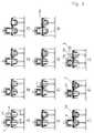
- Figures 3A - 3Lschematically show a cycle of job.
- Figure 3Ashows the preparation of charge 5 and we see that door 27 is open.
- Figure Bshows the conditioning of the load by vacuum and figure C lowering the left plug 4 to open the oven.
- the figure Dshows the rotation of the tanks to load 5 under the oven, before its introduction into it (figure E), to start the treatment cycle.
- Figure Fshows the preparation of a second 5A charge during the cycle of treatment of the first, and Figure G the conditioning of this charge 5A by vacuum.
- Figure Hshows opening the oven and lowering the load 5, and figure I the rotation of the tanks with immediate cooling of the load 5.
- Figure Kshows the introduction of the load 5A in the oven to complete the treatment cycle while the load is cooling 5.
- the figure Lshows the load 5A during the treatment cycle in course and evacuation of charge 5, as well as setting place of a new charge 5B.
- This cycle of operationsshows the great advantage of this installation according to the invention allowing on the one hand prepare one load while the other is in the oven and, above all, to bring and evacuate the load from the oven without vacuum or gas pollution in the oven and without oxidation charges. All the operations described are carried out tightly to the outside by the seal outer 16 is the inner seals 17 and 18.
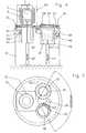
- FIGS 4 and 5show a second embodiment of the installation according to the invention with an oven and three bins.
- Oven 29is similar to oven 1 in the example previous with the same elements such as bedroom heater, turbine, plug 4 which supports the load 5.
- the fixed upper table system 12 and its support 14are also the same as in the previous example, while the rotary table 30 is arranged to carry three tubs and includes three interior gasket packings 31, 32 and 33.
- the outer seal 16is similar to that of the execution described above as well as door 27 with its attached 28.
- the first tankis a loading chamber 34, similar to room 6, the second tank is a gas cooling 35 and the third tank is a cooling chamber with liquid 36, for example oil 37.
- the loading chamber and the gas coolinginclude turbines 38 and 39 while the oil-cooled chamber includes an oil pump 40 for the circulation of the oil.
- This installationalso includes a vacuum pump with valves to be able to evacuate the loading and gas cooling, as well as gas supplies for the rooms and for the oven.
- Each roomincludes in addition to a lifting piston 41, resp. 42, resp. 43.
- FIGS. 6A to 6KAn example of a work cycle with this installation is described using FIGS. 6A to 6K.
- Figure 6Ashows the preparation of charge 5 above the load 34 with door 27 open.
- Figure 6Bshows conditioning of the charge, possibly by vacuum, with door 27 closed and figure C shows the situation after the rotation of the chambers with a 120 ° stroke for bring the load 5 under the oven.
- Figure Dthe charge is introduced into the furnace and the treatment cycle in the oven begins.
- the plugsare upgraded with rotary table after treatment thermal to perform a rotation shown in Figure F. During this rotation, the load slides on the table and afterwards, the oil chamber is under the load, i.e. under the oven.
- Figure Gshows the descent of the charging and immediate cooling thereof in oil.
- FIG Hwe see the preparation of the second load 5A, this possibly being conditioned by the vacuum, as well as the cooling of the first charge 5 in oil.
- Figure Ishows a new rotation of the chambers to bring the second load 5A under the oven before introducing it.
- Figure 6Kfinally shows the situation where the processing cycle is performed for the second charge 5A while the first charge 5 is discharged, to return to the situation of the Figure 6E.
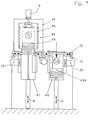
- Figure 7shows a third example of execution of a installation according to the invention with a vacuum oven 44 to hot wall with graphite 45 heating, insulation 46, a circulation turbine 3 for the bass processing temperatures and plugs 49, 49A supporting the load 5.
- the upper fixed table system 12with its door 27 and seal 28, the rotary table 13 driven by the motor 15 and the two seal systems with outer seal 16 and inner seals 17 and 18, east the same as before.
- Bins hanging from the table rotaryare two loading and unloading chambers 47 and 48 with incorporated cooler, comprising both turbines 19 and 20 according to the first embodiment.
- FIGS. 8A to 8Lillustrating an example of a cycle of work done by the installation of figure 7.
- the figure 8Ashows the preparation of load 5 with the door open and Figure 8B shows the packaging of the charge by vacuum.
- Figure Cshows the descent of the plug 49 and the opening of the oven followed by the rotation of chambers according to figure D in order to bring the load 5 under the oven.
- Figure Eshows the introduction of the charge into the oven initiating the treatment cycle.
- the second charge 5Ais prepared and conditioned by vacuum according to figure G.
- Figure Hshows the opening of the oven and the descent of the first load followed by a rotation of the chambers with immediate cooling of the first charge in the cooling chamber 47 (FIG.
- Figure 8Lshows that while the second charge is being treatment, the first charge is discharged and the third charge 5B is amended on the cap, to be then conditioned and treated.
- the same treatment cyclecan apply to a installation where, as a variant, the vacuum oven has a cold wall and graphite insulation.
- Figure 9shows a variant of the installation according to the Figure 7 with an oven 50 similar to the previous oven but additionally having four mechanical stops 51 with their commands 52 to hold or release the load 5A, such as this will emerge from the description according to FIGS. 10A to 10L.
- the upper fixed table 12is similar to the previous case with the door 27 and its seals 28 as well as the support of the table 14. Between the fixed table 12 and the rotary table 13 is finds the same joint system as described above and the rotary table is driven by the motor 15. At the table are suspended at least one oil chamber 53 with its pump system 40 and at least one tank of gas cooling 54 with the turbine 20.
- the tank 54is a pressure chamber and that is why the lift piston provided for the other tanks is here replaced by a lift 55 including a load support 56, linked to a supporting column 57 with a screw 58 which is rotated by a motor 59 with transmission by chain, to raise or lower the elevator. All the elevator device is located within the compound of the pressure chamber. Upward, the pressure chamber is closed by a lower door 60, seals 61 sealing. The loading and unloading of parts can be done by this pressure chamber, or else the installation includes, in addition to this pressure chamber and from the oil chamber, a loading chamber described in the previous examples.
- FIGS. 10A to 10Lschematically show a cycle of possible treatment with the installation of figure 9.
- the Figure 10Ashows the preparation of charge 5, always with the door open, and Figure 10B the packaging load by vacuum, with door 27 closed, followed by the rotation of the chambers to put the load under the oven ( Figure 10C).
- Figure Dthe charge is introduced into the oven to start the treatment cycle and, at the end of the cycle in FIG. E, the load is lowered and the hooks 51 are closed to retain it during the lowering of the stopper by the elevator 55.
- the chambersare rotated to bring the chamber to oil under the oven and, according to G, the load carrier is mounted and the hooks are open.
- the load on the support loadis lowered to be immersed in oil (figure H) for immediate cooling, intensified by a forced flow channel in the oil chamber.
- the second load 5Ais prepared and conditioned by vacuum, then rotated according to Figure K to bring it under the oven for a treatment cycle according to the figure L, while the first load is discharged after draining to chain a new cycle from situation shown in figure D.
- Figure 11shows another embodiment of a the installation according to the invention with a similar oven 62 in oven 29 of FIG. 4, but additionally comprising two half-drawers 63 and 63A, forming the cap, which are controlled by mechanical elements 64.
- Everythingis fixed on the upper fixed table 12 which is similar to that from previous executions and attached to the supports 14.
- Under the fixed tableis a rotary table similar to that from previous versions, with the two joint systems exterior and interior.
- the bins, i.e. the room oil and the cooling chamber (s)are same as in the execution according to figure 4.
- Figures 12A to 12Pshow a work cycle with installation according to figure 11 and will make better understand the role of the two half-drawers 63, 63A.
- Figure 12 Ashows the preparation of load 5
- Figure Bits vacuum conditioning
- figure Cthe rotation of chambers for placing said charge under the oven.
- the half-drawersare moved to open the oven, before the charge is introduced into it and that the half drawers are slightly closed, like this spring of figure E.
- the load support 56is lowered to deposit the load on the plug 63, 63A.
- the ovenis closed and the treatment cycle start. During this time, the rooms are put in rotation and the oil pan is brought under the oven and simultaneously according to I the second charge 5A is prepared and conditioned by vacuum.
- the plug which has the form of two half-drawers 63 and 63Ais not moved vertically, as in the first executions, but is pulled or pushed horizontally.
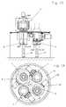
- FIGS 13 and 14schematically show a variant of execution with, for example an oven and four bins hanging on the rotary table.
- the ovencan be the kind of one of the ovens described above, while two bins are provided for loading / unloading and two bins for cooling, either by gas or by liquid, for example oil. All combinations are possible, i.e. that the number and kind of ovens nor the number and kind of containers is in principle limited in an installation according to the invention.
- the executions disclosed in Figures 1 to 14are installations with a fixed table and a rotary table including seals.
- the oven (s)are attached to the fixed table and the hanging trays connected to the rotary table.
- a reverse assemblythat is to say according to which the oven (s) are integral with the rotary table and where the bins are suspended from a table fixed, is also possible.
- the tightness between the fixed table and the rotary tableis ensured by an inflatable external seal and seals, depending on the number of trays, interior inflatable, all ensuring perfect sealing of so as to allow processing of parts, on the one hand, without surface oxidation and pollution-free treatment gases of the oven or without pollution of the oven vacuum and, on the other hand, without cooling the oven during operations.
- FIGS 15 to 17show a first embodiment of such a linear displacement installation with an oven and two bins.
- the ovencorresponds to oven 1 of the execution according to Figure 1, with the same elements, such as room heater, turbine and plug, this oven being fixed on a upper table 65 supported by a support 66.
- a translation table 67is located below the upper table, the translation table carrying two tanks 68 and 69 arranged in loading chambers and cooling and each provided with a piston elevator 8 and 9 and gas supply and connected to a pump vacuum to evacuate the rooms.
- an outer seal 70 and two inner seals 71 and 72are provided, these seals being inflatable like the others joints mentioned above.
- the linear solutionrequires, as shown in Figure 16, two watertight loading doors 73 and 74.
- Figures 18 to 21show an oven installation growing at long load.
- the loadcan be for example a load composed of 6 m long tubes, to be annealed under vacuum or under atmosphere, and it is obvious that the reduction significant of the total length of such an installation where the oven must have the same length, has an advantage considerable.
- the oven 75 of the push type with a long chargeis known per se and includes a sealed channel or carcass 76 and a heating chamber 77 and a circulation turbine atmospheres 78 and a gas supply 79, the whole being arranged in an enclosure 80.
- Each of the two bedrooms loading / unloading 81, 82is provided with a cooler 83 and a gas circulation turbine 84.
- the installationalso includes a fixed plate 85 integral with the oven and equipped with two loading doors 86 or unloading baskets or other objects, such as tubes. These doors are fitted with gaskets.
- the rooms loading or unloadingare integral with a plate mobile 87 mounted on slide. Sealing is ensured by a seal 88 around each loading chamber, these seals being inflatable like the previous seals.
- Each loading or unloading chamberincludes a system 89 for introduction and extraction of load 90 in the cooling channel and in the oven.
- a vacuum pumpallows extraction of chamber in gas loading or unloading position or oxygen. In this way, no trace of oxidation or air pollution is possible.
- the arrangement of the elements of the installationallows reduce the overall dimensions by one or two load lengths of the installation and above all, not to immobilize the loading chamber during cooling of the charge. This is clear if we compare this installation according to the invention with the installations known until now and sold by different houses.
Landscapes
- Chemical & Material Sciences (AREA)
- Engineering & Computer Science (AREA)
- Mechanical Engineering (AREA)
- Crystallography & Structural Chemistry (AREA)
- Thermal Sciences (AREA)
- Physics & Mathematics (AREA)
- Materials Engineering (AREA)
- Metallurgy (AREA)
- Organic Chemistry (AREA)
- General Engineering & Computer Science (AREA)
- Furnace Details (AREA)
- Furnace Charging Or Discharging (AREA)
- Heat Treatments In General, Especially Conveying And Cooling (AREA)
- Physical Or Chemical Processes And Apparatus (AREA)
Abstract
Description
Translated fromFrenchLa présente invention se réfère à une installation pour letraitement thermique d'une charge de pièces métalliques,cette installation comprenant au moins un four sous gaz deprotection ou sous vide et au moins un bac de trempe.The present invention refers to an installation for theheat treatment of a load of metal parts,this installation comprising at least one gas oven ofprotection or vacuum and at least one quench tank.
Les installations connues proposées sur le marché ontl'inconvénient, pour les traitements sous vide d'une chargede pièces métalliques, de devoir charger l'installation àfour froid puis d'effectuer le vide pour évacuer l'oxygènede la chambre de chauffe du four. Après le traitement on estobligé de refroidir le tout dans le four y compris lacharge. Sans sas ou bac de chargement il est alorsimpossible de travailler avec le four chaud, car touteprésence d'oxygène détériorerait les éléments chauffants.The known installations offered on the market havethe disadvantage, for vacuum treatments of a loadmetal parts, having to load the installation atcold oven then vacuum to evacuate oxygenfrom the oven heating chamber. After the treatment we areforced to cool everything in the oven including thecharge. Without airlock or loading bin it is thenimpossible to work with the hot oven, because anypresence of oxygen would damage the heating elements.
A partir de cet état de la technique connue, un but de laprésente invention est de réaliser une installation detraitement thermique ne nécessitant pas de refroidir lefour, et permettant de traiter les pièces sans oxydation desurface et sans pollution des gaz de traitement du four ousans pollution du vide du four.From this known state of the art, a goal of thepresent invention is to provide an installation ofheat treatment that does not require cooling theoven, and allowing parts to be treated without oxidation ofsurface and without pollution of the furnace treatment gases orwithout pollution of the oven vacuum.
En outre sont connus des fours à passage ou des fourspoussant à charge longue dont l'installation nécessite unetrès grande surface et surtout une grande longueur et dontle cycle de travail pour la charge et la décharge du fouret, de plus, long.In addition, passage ovens or ovens are known.pushing with long load whose installation requires avery large area and especially a great length and of whichthe working cycle for charging and discharging the ovenand, moreover, long.
Partant de cet état de la technique connue, un autre but dela présente invention est de réduire sensiblement aussi bien la longueur d'une telle installation que le temps detraitement.Starting from this known state of the art, another aim ofthe present invention is to significantly reduce as wellthe length of such an installation that the time oftreatment.
Ces buts sont atteints grâce aux moyens définis dans larevendication indépendante 1.These goals are achieved through the means defined in the
L'invention sera expliquée en détail, en se référant auxdessins ci-annexés qu'en présentent, à titre d'exemples, desformes d'exécution.
- La figure 1
- est une vue en élévation schématiqued'une forme d'exécution del'installation selon l'invention,
- la figure 2
- est une vue en plan de dessusschématique de l'installation de lafigure 1,
- les figures 3A à 3L
- sont un descriptif d'un cycle detravail de l'installation selon lafigure 1,
- la figure 4
- est une vue en élévation schématiqued'une deuxième forme d'exécutionselon l'invention,
- la figure 5
- est une vue en plan de dessusschématique de l'installation de lafigure 4,
- les figures 6A - 6K
- sont un descriptif schématique d'uncycle de travail de l'installationselon les figures 4 et 5,
- la figure 7
- est une vue en élévation schématiqued'une troisième forme d'exécution del'installation selon l'invention,
- les figures 8A - 8L
- sont un descriptif schématique d'uncycle de travail de l'installationselon la figure 7,
- la figure 9
- est une vue en élévation schématiqued'une autre installation selonl'invention,
- les figures 10A - 10L
- sont un descriptif schématique d'uncycle de travail de l'installationselon la figure 10,
- la figure 11
- est une vue en élévation schématiqued'une autre installation selonl'invention,
- les figures 12A - 12P
- sont un descriptif schématique d'uncycle de travail de l'installationselon la figure 11,
- la figure 13
- est une vue en élévation schématiqued'une installation avec un four etquatre bac,
- la figure 14
- est une vue en plan de dessusschématique de l'installation selonla figure 13,
- la figure 15
- est une vue en élévation transversaled'une installation en ligne selonl'invention,
- la figure 16
- est une vue en élévationlongitudinale schématique del'installation selon la figure 15,
- la figure 17
- est une vue en plan de dessusschématique de l'installation selonla figure 15,
- la figure 18
- est une vue en élévationlongitudinale schématique d'uneinstallation avec four poussant àcharge longue,
- la figure 19
- est une vue de front schématique d'unfour de l'installation selon lafigure 18,
- la figure 20
- est une vue de front d'un bac del'installation selon la figure 18, et
- la figure 21
- est une vue en plan de dessusschématique de l'installation de lafigure 18.
- Figure 1
- is a schematic elevational view of an embodiment of the installation according to the invention,
- figure 2
- is a schematic top plan view of the installation of FIG. 1,
- Figures 3A to 3L
- are a description of a work cycle of the installation according to FIG. 1,
- figure 4
- is a schematic elevation view of a second embodiment according to the invention,
- figure 5
- is a schematic top plan view of the installation of FIG. 4,
- Figures 6A - 6K
- are a schematic description of a work cycle of the installation according to FIGS. 4 and 5,
- figure 7
- is a schematic elevational view of a third embodiment of the installation according to the invention,
- Figures 8A - 8L
- are a schematic description of a work cycle of the installation according to FIG. 7,
- figure 9
- is a schematic elevational view of another installation according to the invention,
- Figures 10A - 10L
- are a schematic description of a work cycle of the installation according to FIG. 10,
- figure 11
- is a schematic elevational view of another installation according to the invention,
- Figures 12A - 12P
- are a schematic description of a work cycle of the installation according to FIG. 11,
- figure 13
- is a schematic elevation view of an installation with an oven and four tanks,
- figure 14
- is a schematic top plan view of the installation according to FIG. 13,
- figure 15
- is a cross-sectional view of an on-line installation according to the invention,
- figure 16
- is a schematic longitudinal elevation view of the installation according to FIG. 15,
- figure 17
- is a schematic top plan view of the installation according to FIG. 15,
- figure 18
- is a schematic longitudinal elevation view of an installation with a long-load pushing oven,
- figure 19
- is a schematic front view of an oven of the installation according to FIG. 18,
- figure 20
- is a front view of a tank of the installation according to FIG. 18, and
- figure 21
- is a schematic top plan view of the installation of FIG. 18.
Les figures 1 et 2 montrent schématiquement une premièreforme exécution d'une installation selon l'invention avec unfour de traitement pour une température maxima de 1100°C etdeux bacs montés sur une table rotative. Cette installationpermet par exemple des traitement d'austénitisation, derecuit, de revenu, de frittage ou de brasage. Le four 1 comprend une chambre de chauffage 2 avec une turbine decirculation des atmosphères 3, un bouchon 4 comme support dela charge à traiter 5 et deux bacs, c'est-à-dire. deuxchambres de chargement ou refroidissement 6 et 7. Le bouchonsupport de charge est déplacé verticalement par les deuxpistons élévateurs 8 et 9, comme c'est indiqué par les deuxflèches doubles. Ces pistons élévateurs sont prévus pour lechargement ou déchargement des charges dans le four ou dansles bacs, comme cela ressortira du descriptif d'un cycle detravail avec cette installation. Le four comprend en outreun corps de chauffe 10 et une double chemise isolée 11 selonl'art de la technique connue.Figures 1 and 2 schematically show a firstembodiment of an installation according to the invention with atreatment oven for a maximum temperature of 1100 ° C andtwo tanks mounted on a rotary table. This installationallows for example austenitization treatment,annealing, tempering, sintering or soldering. The
Le four 1 est fixé sur une table supérieure 12 tandis queles bacs, c'est-à-dire les chambres de chargement ourefroidissement 6 et 7 avec les pistons élévateurs 8 et 9sont fixés à une table rotative 13. La table fixe 12 estmontée sur un support 14. La table rotative 13 est entraínéeen rotation par un moteur 15. Entre la table fixe et latable rotative se trouvent deux jeux de joints, un jointextérieur 16 pour établir l'étanchéité au gaz et au vide etdeux joints intérieurs 17 et 18, qui forment une premièrebarrière d'étanchéité entre les bacs et la table fixesupérieure. Tous les joints sont des joints gonflables,connus en soi dans l'art antérieur, et sont partiellementdégonflés dans le cas où la table rotative est mise enrotation, et ensuite gonflés pour assurer l'étanchéité.The
Chaque chambre de chargement ou de refroidissement 6 et 7comprend une turbine de circulation des atmosphères 19 et20, une pompe à vide 21 commune qui est reliée par desvannes 22 et 23 auxdites chambres de chargement ou refroidissement. Chaque bac 6 et 7 comprend une amenée 24 et25 d'azote et le four comprend une amenée de gaz 26.Each loading or
La table supérieure comprend une porte 27 qui possède unjoint 28 et qui permet l'introduction de la charge dans undes bacs. Un remplissage à l'azote par exemple ou un autregaz permet de transférer la charge à traiter dans le foursous gaz de protection ou sous vide. Le four restanttoujours à température permet d'effectuer un des traitementsprécités. A la fin du cycle de chauffe, la charge est évacuédans une des deux chambres pour refroidissement. Avant larotation pour le transfert et le refroidissement, on aurapréparé une nouvelle charge à traiter dans le bac libre detoute charge. Il est ainsi possible de traiter, paralternance, des pièces sans oxydation de surface et sansrefroidissement du four ainsi que sans pollution de gaz detraitement ou du vide du four.The upper table includes a
Il est évident que l'on peut réaliser une installation avecdes bacs, c'est-à-dire. des chambres dechargement/déchargement ou refroidissement à gaz ou àl'huile fixées au support et à la table supérieure etprévoir un ou plusieurs four(s) rotatif(s).It is obvious that an installation can be carried out withbins, that is to say. rooms ofgas / gas loading / unloading or coolingthe oil fixed to the support and to the upper table andprovide one or more rotary oven (s).
Les figures 3A - 3L) montrent schématiquement un cycle detravail. La figure 3A montre la préparation de la charge 5et on voit que la porte 27 est ouverte. La figure B montrele conditionnement de la charge par le vide et la figure Cla descente du bouchon gauche 4 pour l'ouverture du four. Lafigure D montre la rotation des bacs pour mettre la charge 5sous le four, avant son introduction dans celui-ci (figureE), pour entamer le cycle de traitement. La figure F montrela préparation d'une deuxième charge 5A pendant le cycle de traitement de la première, et la figure G le conditionnementde cette charge 5A par le vide. La figure H montrel'ouverture du four et la descente de la charge 5, et lafigure I la rotation des bacs avec refroidissement immédiatde la charge 5. La figure K montre l'introduction de lacharge 5A dans le four pour effectuer le cycle de traitementpendant le refroidissement de la charge 5. Enfin, la figureL montre la charge 5A en cours de cycle de traitement encours et l'évacuation de la charge 5, ainsi que la mise enplace d'une nouvelle charge 5B.Figures 3A - 3L) schematically show a cycle ofjob. Figure 3A shows the preparation of
Ce cycle des opérations montre le grand avantage de cetteinstallation selon l'invention permettant d'une part depréparer une charge tandis que l'autre est dans le four et,surtout, d'amener et d'évacuer la charge du four sanspollution du vide ou du gaz dans le four et sans oxydationdes charges. Toutes les opérations décrites s'effectuentd'une manière étanche envers l'extérieur par le jointextérieur 16 est les joints intérieurs 17 et 18.This cycle of operations shows the great advantage of thisinstallation according to the invention allowing on the one handprepare one load while the other is in the oven and,above all, to bring and evacuate the load from the oven withoutvacuum or gas pollution in the oven and without oxidationcharges. All the operations described are carried outtightly to the outside by the sealouter 16 is the
Les figures 4 et 5 montrent une deuxième forme d'exécutionde l'installation selon l'invention avec un four et troisbacs. Le four 29 est similaire au four 1 de l'exempleprécédent avec les mêmes éléments tels que chambre dechauffe, turbine, bouchon 4 qui supporte la charge 5. Lesystème de la table supérieure fixe 12 et son support 14sont également les mêmes que dans l'exemple précédent,tandis que la table rotative 30 est agencée pour portertrois bacs et comprend trois garnitures de joints intérieurs31, 32 et 33. Le joint extérieur 16 est similaire à celui del'exécution décrite plus haut ainsi que la porte 27 avec sonjoint 28.Figures 4 and 5 show a second embodimentof the installation according to the invention with an oven and threebins.
Le premier bac est une chambre de chargement 34, similaire àla chambre 6, le deuxième bac est une chambre derefroidissement sous gaz 35 et le troisième bac est unechambre de refroidissement avec un liquide 36, par exemplede l'huile 37. La chambre de chargement et la chambre derefroidissement sous gaz comprennent des turbines 38 et 39tandis que la chambre à refroidissement à l'huile comprendune pompe à huile 40 pour la circulation de l'huile. Cetteinstallation comprend aussi une pompe à vide avec des vannespour pouvoir évacuer les chambres de chargement et derefroidissement sous gaz, ainsi que des amenées de gaz pourles chambres et pour le four. Chaque chambre comprend enoutre un piston élévateur 41, resp. 42, resp. 43.The first tank is a
Un exemple de cycle de travail avec cette installation estdécrit à l'aide des figures 6A à 6K. La figure 6A montre lapréparation de la charge 5 en-dessus de la chambre dechargement 34 avec la porte 27 ouverte. La figure 6B montrele conditionnement de la charge, éventuellement par le vide,avec la porte 27 fermée et la figure C montre la situationaprès la rotation des chambres avec une course de 120 ° pouramener la charge 5 sous le four. Selon la figure D, lacharge est introduite dans le four et le cycle de traitementdans le four commence. Selon la figure E, les bouchons sontmis à niveau avec la table rotative après le traitementthermique pour effectuer une rotation montrée à la figure F.Pendant cette rotation, la charge glisse sur la table etaprès, la chambre à huile se trouve sous la charge, c'est-à-diresous le four. La figure G montre la descente de lacharge et le refroidissement immédiat de celle-ci dansl'huile. Dans la figure H on voit la préparation de ladeuxième charge 5A, celle-ci étant éventuellementconditionnée par le vide, ainsi que le refroidissement de la première charge 5 dans l'huile. La figure I montre unenouvelle rotation des chambres pour amener la deuxièmecharge 5A sous le four avant de l'y introduire. La figure 6Kenfin montre la situation où le cycle de traitement esteffectué pour la deuxième charge 5A tandis que la premièrecharge 5 est évacuée, pour revenir à la situation de lafigure 6E.An example of a work cycle with this installation isdescribed using FIGS. 6A to 6K. Figure 6A shows thepreparation of
La figure 7 montre un troisième exemple d'exécution d'uneinstallation selon l'invention avec un four à vide 44 àparoi chaude avec un chauffage graphite 45, une isolation46, une turbine de circulation 3 pour les bassestempératures de traitement et les bouchons 49, 49Asupportant la charge 5. Le système de table fixe supérieure12 avec sa porte 27 et joint 28, la table rotative 13entraínée par le moteur 15 et les deux systèmes de jointsavec joint extérieur 16 et joints intérieurs 17 et 18, estle même qu'auparavant. Les bacs suspendus à la tablerotative sont deux chambres de chargement et déchargement 47et 48 avec refroidisseur incorporé, comprenant les deuxturbines 19 et 20 selon la première forme d'exécution.Figure 7 shows a third example of execution of ainstallation according to the invention with a
Les figures 8A à 8L illustrant un exemple de cycle detravail effectué par l'installation de la figure 7. Lafigure 8A montre la préparation de la charge 5 avec la porteouverte et la figure 8B montre le conditionnement de lacharge par le vide. La figure C montre la descente dubouchon 49 et l'ouverture du four suivie de la rotation deschambres selon la figure D en vue d'amener la charge 5 sousle four. La figure E montre l'introduction de la charge dansle four initiant le cycle de traitement. Pendant ce temps,selon la figure F, la deuxième charge 5A est préparée etconditionnée par le vide selon la figure G. La figure H montre l'ouverture du four et la descente de la premièrecharge suivie d'une rotation des chambres avecrefroidissement immédiat de la première charge dans lachambre de refroidissement 47 (figure I) et ensuite, à lafigure K, l'introduction de la deuxième charge 5A dans lefour pour le cycle de traitement, tandis que la premièrecharge est toujours encore refroidie. La figure 8L montreque, tandis que la deuxième charge est en cours detraitement, la première charge est évacuée et la troisièmecharge 5B est amendée sur le bouchon, pour être ensuiteconditionnée et traitée.FIGS. 8A to 8L illustrating an example of a cycle ofwork done by the installation of figure 7. Thefigure 8A shows the preparation of
Le même cycle de traitement peut s'appliquer à uneinstallation où, comme variante d'exécution, le four à videpossède une paroi froide et une isolation en graphite.The same treatment cycle can apply to ainstallation where, as a variant, the vacuum ovenhas a cold wall and graphite insulation.
La figure 9 montre une variante de l'installation selon lafigure 7 avec un four 50 similaire au four précédent maispossédant en outre quatre arrêts mécaniques 51 avec leurcommandes 52 pour retenir ou libérer la charge 5A, commecela ressortira du descriptif selon les figures 10A à 10L.La table fixe supérieure 12 est similaire au cas précédentavec la porte 27 et ses joints 28 ainsi que le support de latable 14. Entre la table fixe 12 et la table rotative 13 setrouve le même système de joints que décrits auparavant etla table rotative est entraínée par le moteur 15. A la tablerotative sont suspendue au moins une chambre à huile 53 avecson système de pompe 40 et au moins un bac derefroidissement à gaz 54 avec la turbine 20.Figure 9 shows a variant of the installation according to theFigure 7 with an
Le bac 54 est une chambre à pression et c'est pourquoi quele piston ascenseur prévu pour les autres bacs est iciremplacé par un ascenseur 55 comprenant un support de charge 56, lié à une colonne portante 57 avec une vis 58 qui estmise en rotation par un moteur 59 avec transmission parchaíne, pour faire monter ou descendre l'ascenseur. Tout ledispositif de l'ascenseur se trouve dans l'enceinte de lachambre à pression. Vers le haut, la chambre sous pressionest fermée par une porte inférieure 60, des joints 61assurant l'étanchéité. Le chargement et déchargement despièces peut se faire par cette chambre à pression, ou alorsl'installation comprend, en plus de cette chambre à pressionet de la chambre à huile, une chambre de chargement décritedans les exemples précédents.The
Les figures 10A à 10L montrent schématiquement un cycle detraitement possible avec l'installation de la figure 9. Lafigure 10A montre la préparation de la charge 5, toujoursavec la porte ouverte, et la figure 10B le conditionnementde la charge par le vide, avec la porte 27 fermée, suivi dela rotation des chambres pour mettre la charge sous le four(figure 10C). Ensuite, selon la figure D, la charge estintroduite dans le four pour entamer le cycle de traitementet, en fin de cycle à la figure E, la charge est descendueet les crochets 51 sont fermés pour la retenir pendant ladescente du bouchon par l'ascenseur 55. Ensuite, selon F,les chambres sont mises en rotation pour amener la chambre àhuile sous le four et, selon G, le support de charge estmonté et les crochets sont ouverts. La charge sur le supportde charge est descendue pour être immergée dans l'huile(figure H) pour un refroidissement immédiat, intensifié parun canal de flux forcé dans la chambre à huile. Selon lafigure I, la deuxième charge 5A est préparée et conditionnéepar le vide, puis mise en rotation selon la figure K pourl'amener sous le four pour un cycle de traitement selon lafigure L, tandis que la première charge est évacuée après égouttage pour enchaíner un nouveau cycle à partir de lasituation représentée à la figure D.FIGS. 10A to 10L schematically show a cycle ofpossible treatment with the installation of figure 9. TheFigure 10A shows the preparation of
La figure 11 montre une autre forme d'exécution d'unel'installation selon l'invention avec un four 62 similaireau four 29 de la figure 4, mais comportant en plus deuxdemi-tiroirs 63 et 63A, formant le bouchon, qui sontcommandés par des éléments mécaniques 64. Le tout est fixésur la table fixe supérieure 12 qui est similaire à celledes exécutions précédentes et attachés aux supports 14. Sousla table fixe se trouve une table rotative similaire à celledes exécutions précédentes, avec les deux systèmes de jointsextérieurs et intérieurs. Les bacs, c'est-à-dire la chambreà huile et la ou les chambre(s) de refroidissement, sont lesmêmes que dans l'exécution selon la figure 4.Figure 11 shows another embodiment of athe installation according to the invention with a
Les figures 12A à 12P montrent un cycle de travail avecl'installation selon la figure 11 et feront mieux comprendrele rôle des deux demi-tiroirs 63, 63A. La figure 12 A montrela préparation de la charge 5, la figure B sonconditionnement par le vide, et la figure C la rotation deschambres pour placer ladite charge sous le four. Ensuite,selon D, les demi-tiroirs sont déplacés pour ouvrir le four,avant que la charge est introduite dans ce dernier et queles demi-tiroirs sont légèrement refermés, comme celaressort de la figure E. A la figure F le support de charge56 est descendu pour déposer la charge sur le bouchon 63,63A. Selon G, le four est fermé et le cycle de traitementcommence. Fendant ce temps, les chambres sont mises enrotation et le bac d'huile est amené sous le four etsimultanément selon I la deuxième charge 5A est préparée etconditionnée par le vide. Dans la figure K une préouverturedu bouchon, c'est-à-dire des demi-tiroirs est effectuée, et le support de charge est déplacé vers le haut. Selon lafigure L le four est complètement ouvert et à la figure M,la charge est immergée et refroidie immédiatement dans lachambre à huile avec canal de flux forcé. Ensuite, selon lafigure N, les chambres sont de nouveau mises en rotation, etla deuxième charge 5A se trouve sous le four. Dans la figureO, on introduit la charge 5A dans le four selon les figuresC à G, le cycle de traitement dans le four commence, tandisqu'après égouttage, la première charge 5 est évacuée. Enfin,selon la figure P, les chambres sont mises en rotation pouremmener le bac à huile sous le four tandis qu'une nouvellecharge 5B est préparée pour subir le cycle selon les figures12A et suivantes.Figures 12A to 12P show a work cycle withinstallation according to figure 11 and will make better understandthe role of the two half-
Dans cette forme d'exécution, on observe que le bouchon quiprésente la forme de deux demi-tiroirs 63 et 63A n'est pasdéplacé verticalement, comme dans les premières exécutions,mais est tiré ou poussé horizontalement.In this embodiment, it is observed that the plug whichhas the form of two half-
Les figures 13 et 14 montrent schématiquement une varianted'exécution avec, par exemple un four et quatre bacssuspendus à la table rotative. Le four peut être du genre del'un des fours décrits auparavant, tandis que deux bacs sontprévus pour le chargement/déchargement et deux bacs pour lerefroidissement, soit par gaz, soit par liquide, par exemplel'huile. Toutes combinaisons sont possibles, c'est-à-direque le nombre et le genre de fours, ni le nombre et le genrede bacs est en principe limité dans une installation selonl'invention.Figures 13 and 14 schematically show a variantof execution with, for example an oven and four binshanging on the rotary table. The oven can be the kind ofone of the ovens described above, while two bins areprovided for loading / unloading and two bins forcooling, either by gas or by liquid, for exampleoil. All combinations are possible, i.e.that the number and kind of ovens nor the number and kindof containers is in principle limited in an installation according tothe invention.
Les exécutions divulguées dans les figures 1 à 14 sont desinstallations avec une table fixe et une table rotativecomprenant des joints. Préférentiellement, le ou les fours sont solidaires de la table fixe et les bacs suspendusreliés à la table rotative. Mais un montage inverse, c'est-à-direselon lequel le ou les fours sont solidaires de latable rotative et où les bacs sont suspendus à une tablefixe, est également envisageable. Dans toutes ces solutionsou arrangements, l'étanchéité entre la table fixe et latable rotative est assurée par un joint extérieur gonflableet des joints, selon le nombre de bacs, intérieursgonflables, le tout assurant une étanchéité parfaite desorte à permettre un traitement de pièces, d'une part, sansoxydation de surface et sans pollution des gaz de traitementdu four ou sans pollution du vide du four et, d'autre part,sans refroidissement du four pendant les opérations.The executions disclosed in Figures 1 to 14 areinstallations with a fixed table and a rotary tableincluding seals. Preferably, the oven (s)are attached to the fixed table and the hanging traysconnected to the rotary table. But a reverse assembly, that is to sayaccording to which the oven (s) are integral with therotary table and where the bins are suspended from a tablefixed, is also possible. In all these solutionsor arrangements, the tightness between the fixed table and therotary table is ensured by an inflatable external sealand seals, depending on the number of trays, interiorinflatable, all ensuring perfect sealing ofso as to allow processing of parts, on the one hand, withoutsurface oxidation and pollution-free treatment gasesof the oven or without pollution of the oven vacuum and, on the other hand,without cooling the oven during operations.
Cette conception de déplacement relatif entre four(s) etbac(s), le tout sous une étanchéité parfaite. n'est pasnécessairement giratoire et limitée à une table rotative,mais peut être appliquée à un système de déplacementlinéaire. Les figures 15 à 21 montrent deux exemplesd'exécution de fours et bacs à déplacement relatif linéaire.This concept of relative displacement between oven (s) andtray (s), all under perfect sealing. is notnecessarily gyratory and limited to a rotary table,but can be applied to a displacement systemlinear. Figures 15 to 21 show two examplesexecution of ovens and trays with linear relative displacement.
Les figures 15 à 17 montrent une première forme d'exécutiond'une telle installation à déplacement linéaire avec un fouret deux bacs. Le four correspond au four 1 de l'exécutionselon la figure 1, avec les mêmes éléments, tels que chambrede chauffe, turbine et bouchon, ce four étant fixé sur unetable supérieure 65 supportée par un support 66. Analogue àl'exécution rotative une table de translation 67 se trouveen dessous de la table supérieure, la table de translationportant deux bacs 68 et 69 agencés en chambres de chargementet de refroidissement et pourvu, chacun, d'un pistonélévateur 8 et 9 et d'amenée de gaz et reliés à une pompe àvide pour évacuer les chambres. Pour assurer l'étanchéité, un joint extérieur 70 et deux joints intérieurs 71 et 72sont prévus, ces joints étant gonflables comme les autresjoints évoqués précédemment.Figures 15 to 17 show a first embodimentof such a linear displacement installation with an ovenand two bins. The oven corresponds to
Le fonctionnement de cette installation est analogue aufonctionnement des installations de type rotatif et lesmêmes cycles de travail peuvent être appliqués pour lefonctionnement d'une installation de type linéaire que pourune installation de type rotatif, et il suffit de remplacerle terme "rotation" par "déplacement linéaire". Il est aussientendu qu'au lieu de l'installation montrée aux figures 15à 17, les installations décrites dans les exemplesprécédents sont applicables analogiquement.The operation of this installation is analogous tooperation of rotary type installations andsame work cycles can be applied for theoperation of a linear type installation only fora rotary type installation, and just replacethe term "rotation" by "linear displacement". It is alsounderstood that instead of the installation shown in Figures 15to 17, the installations described in the examplesabove are applicable analogically.
La solution linéaire exige, comme montré à la figure 16,deux portes étanches de chargement 73 et 74.The linear solution requires, as shown in Figure 16,two
Les figures 18 à 21 montrent une installation à fourpoussant à charge longue. La charge peut être par exempleune charge composée de tubes de 6 m de long, à recuire sousvide ou sous atmosphère, et il est évident que la réductionimportante de la longueur totale d'une telle installation oùle four doit avoir la même longueur, présente un avantageconsidérable.Figures 18 to 21 show an oven installationgrowing at long load. The load can be for examplea load composed of 6 m long tubes, to be annealed undervacuum or under atmosphere, and it is obvious that the reductionsignificant of the total length of such an installation wherethe oven must have the same length, has an advantageconsiderable.
Le four 75 du type poussant à charge longue est connu en soiet comprend un canal ou une carcasse étanche 76 et unechambre chauffante 77 ainsi qu'une turbine de circulationdes atmosphère 78 et une amenée de gaz 79, le tout étantagencé dans une enceinte 80. Chacune des deux chambres dechargement/déchargement 81, 82 est munie d'un refroidisseur83 et d'une turbine 84 de circulation des gaz.L'installation comprend en outre une platine fixe 85 solidaire du four et équipée de deux portes 86 de chargementou déchargement de paniers ou autres objets, tels que tubes.Ces portes sont munies de joints d'étanchéité. Les chambresde chargement ou déchargement sont solidaires d'une platinemobile 87 montée sur glissière. L'étanchéité est assurée parun joint 88 autour de chaque chambre de chargement, cesjoints étant gonflables comme les joints précédents. Chaquechambre de chargement ou déchargement comprend un systèmed'entraínement 89 permettant l'introduction et l'extractionde la charge 90 dans le canal de refroidissement et dans lefour. En outre, une pompe à vide permet d'extraire de lachambre en position de chargement ou déchargement les gaz oul'oxygène. De cette façon, aucune trace d'oxydation ou depollution de l'atmosphère est possible.The
La disposition des éléments de l'installation permet deréduire d'une ou de deux longueurs de charge l'encombrementde l'installation et surtout, de ne pas immobiliser lachambre de chargement durant le refroidissement de lacharge. Ceci ressort clairement si l'on compare cetteinstallation selon l'invention avec les installationsconnues jusqu'a présent et vendues par différentes maisons.The arrangement of the elements of the installation allowsreduce the overall dimensions by one or two load lengthsof the installation and above all, not to immobilize theloading chamber during cooling of thecharge. This is clear if we compare thisinstallation according to the invention with the installationsknown until now and sold by different houses.
Claims (15)
Translated fromFrenchPriority Applications (4)
| Application Number | Priority Date | Filing Date | Title |
|---|---|---|---|
| EP98811062AEP0995805B9 (en) | 1998-10-23 | 1998-10-23 | Heat treatment installation for a batch of metallic workpieces |
| ES98811062TES2199416T3 (en) | 1998-10-23 | 1998-10-23 | INSTALLATION FOR THE THERMAL TREATMENT OF A LOAD OF METAL PARTS. |
| AT98811062TATE241705T1 (en) | 1998-10-23 | 1998-10-23 | HEAT TREATMENT SYSTEM FOR A BATCH OF METALLIC WORKPIECES |
| DE69815108TDE69815108T2 (en) | 1998-10-23 | 1998-10-23 | Heat treatment plant for a batch of metallic workpieces |
Applications Claiming Priority (1)
| Application Number | Priority Date | Filing Date | Title |
|---|---|---|---|
| EP98811062AEP0995805B9 (en) | 1998-10-23 | 1998-10-23 | Heat treatment installation for a batch of metallic workpieces |
Publications (3)
| Publication Number | Publication Date |
|---|---|
| EP0995805A1true EP0995805A1 (en) | 2000-04-26 |
| EP0995805B1 EP0995805B1 (en) | 2003-05-28 |
| EP0995805B9 EP0995805B9 (en) | 2004-01-28 |
Family
ID=8236401
Family Applications (1)
| Application Number | Title | Priority Date | Filing Date |
|---|---|---|---|
| EP98811062AExpired - LifetimeEP0995805B9 (en) | 1998-10-23 | 1998-10-23 | Heat treatment installation for a batch of metallic workpieces |
Country Status (4)
| Country | Link |
|---|---|
| EP (1) | EP0995805B9 (en) |
| AT (1) | ATE241705T1 (en) |
| DE (1) | DE69815108T2 (en) |
| ES (1) | ES2199416T3 (en) |
Cited By (30)
| Publication number | Priority date | Publication date | Assignee | Title |
|---|---|---|---|---|
| US7583990B2 (en) | 2003-08-01 | 2009-09-01 | Dexcom, Inc. | System and methods for processing analyte sensor data |
| US7774145B2 (en) | 2003-08-01 | 2010-08-10 | Dexcom, Inc. | Transcutaneous analyte sensor |
| US8275437B2 (en) | 2003-08-01 | 2012-09-25 | Dexcom, Inc. | Transcutaneous analyte sensor |
| US9610031B2 (en) | 2004-07-13 | 2017-04-04 | Dexcom, Inc. | Transcutaneous analyte sensor |
| US9610034B2 (en) | 2001-01-02 | 2017-04-04 | Abbott Diabetes Care Inc. | Analyte monitoring device and methods of use |
| US9649069B2 (en) | 2003-08-22 | 2017-05-16 | Dexcom, Inc. | Systems and methods for replacing signal artifacts in a glucose sensor data stream |
| US9750441B2 (en) | 2003-12-09 | 2017-09-05 | Dexcom, Inc. | Signal processing for continuous analyte sensor |
| US9804114B2 (en) | 2001-07-27 | 2017-10-31 | Dexcom, Inc. | Sensor head for use with implantable devices |
| US9833143B2 (en) | 2004-05-03 | 2017-12-05 | Dexcom, Inc. | Transcutaneous analyte sensor |
| US9895089B2 (en) | 2003-08-01 | 2018-02-20 | Dexcom, Inc. | System and methods for processing analyte sensor data |
| US9986942B2 (en) | 2004-07-13 | 2018-06-05 | Dexcom, Inc. | Analyte sensor |
| US10201301B2 (en) | 2005-11-01 | 2019-02-12 | Abbott Diabetes Care Inc. | Analyte monitoring device and methods of use |
| US10231654B2 (en) | 2005-11-01 | 2019-03-19 | Abbott Diabetes Care Inc. | Analyte monitoring device and methods of use |
| US10349873B2 (en) | 2006-10-04 | 2019-07-16 | Dexcom, Inc. | Analyte sensor |
| US10478108B2 (en) | 1998-04-30 | 2019-11-19 | Abbott Diabetes Care Inc. | Analyte monitoring device and methods of use |
| US10610137B2 (en) | 2005-03-10 | 2020-04-07 | Dexcom, Inc. | System and methods for processing analyte sensor data for sensor calibration |
| US10653835B2 (en) | 2007-10-09 | 2020-05-19 | Dexcom, Inc. | Integrated insulin delivery system with continuous glucose sensor |
| US10813577B2 (en) | 2005-06-21 | 2020-10-27 | Dexcom, Inc. | Analyte sensor |
| US10966609B2 (en) | 2004-02-26 | 2021-04-06 | Dexcom, Inc. | Integrated medicament delivery device for use with continuous analyte sensor |
| US10980461B2 (en) | 2008-11-07 | 2021-04-20 | Dexcom, Inc. | Advanced analyte sensor calibration and error detection |
| US11000215B1 (en) | 2003-12-05 | 2021-05-11 | Dexcom, Inc. | Analyte sensor |
| US11102306B2 (en) | 2008-02-21 | 2021-08-24 | Dexcom, Inc. | Systems and methods for processing, transmitting and displaying sensor data |
| US11246990B2 (en) | 2004-02-26 | 2022-02-15 | Dexcom, Inc. | Integrated delivery device for continuous glucose sensor |
| US11331022B2 (en) | 2017-10-24 | 2022-05-17 | Dexcom, Inc. | Pre-connected analyte sensors |
| US11350862B2 (en) | 2017-10-24 | 2022-06-07 | Dexcom, Inc. | Pre-connected analyte sensors |
| US11373347B2 (en) | 2007-06-08 | 2022-06-28 | Dexcom, Inc. | Integrated medicament delivery device for use with continuous analyte sensor |
| US11382539B2 (en) | 2006-10-04 | 2022-07-12 | Dexcom, Inc. | Analyte sensor |
| US11432772B2 (en) | 2006-08-02 | 2022-09-06 | Dexcom, Inc. | Systems and methods for replacing signal artifacts in a glucose sensor data stream |
| US11559260B2 (en) | 2003-08-22 | 2023-01-24 | Dexcom, Inc. | Systems and methods for processing analyte sensor data |
| US11564602B2 (en) | 2003-11-19 | 2023-01-31 | Dexcom, Inc. | Integrated receiver for continuous analyte sensor |
Families Citing this family (17)
| Publication number | Priority date | Publication date | Assignee | Title |
|---|---|---|---|---|
| US9066695B2 (en) | 1998-04-30 | 2015-06-30 | Abbott Diabetes Care Inc. | Analyte monitoring device and methods of use |
| US6949816B2 (en) | 2003-04-21 | 2005-09-27 | Motorola, Inc. | Semiconductor component having first surface area for electrically coupling to a semiconductor chip and second surface area for electrically coupling to a substrate, and method of manufacturing same |
| US6175752B1 (en) | 1998-04-30 | 2001-01-16 | Therasense, Inc. | Analyte monitoring device and methods of use |
| US8346337B2 (en) | 1998-04-30 | 2013-01-01 | Abbott Diabetes Care Inc. | Analyte monitoring device and methods of use |
| US8465425B2 (en) | 1998-04-30 | 2013-06-18 | Abbott Diabetes Care Inc. | Analyte monitoring device and methods of use |
| US9282925B2 (en) | 2002-02-12 | 2016-03-15 | Dexcom, Inc. | Systems and methods for replacing signal artifacts in a glucose sensor data stream |
| US9247901B2 (en) | 2003-08-22 | 2016-02-02 | Dexcom, Inc. | Systems and methods for replacing signal artifacts in a glucose sensor data stream |
| US8845536B2 (en) | 2003-08-01 | 2014-09-30 | Dexcom, Inc. | Transcutaneous analyte sensor |
| US7986986B2 (en) | 2003-08-01 | 2011-07-26 | Dexcom, Inc. | System and methods for processing analyte sensor data |
| US8369919B2 (en) | 2003-08-01 | 2013-02-05 | Dexcom, Inc. | Systems and methods for processing sensor data |
| US8160669B2 (en) | 2003-08-01 | 2012-04-17 | Dexcom, Inc. | Transcutaneous analyte sensor |
| US8886273B2 (en) | 2003-08-01 | 2014-11-11 | Dexcom, Inc. | Analyte sensor |
| US8886272B2 (en) | 2004-07-13 | 2014-11-11 | Dexcom, Inc. | Analyte sensor |
| US8452368B2 (en) | 2004-07-13 | 2013-05-28 | Dexcom, Inc. | Transcutaneous analyte sensor |
| WO2007102842A2 (en) | 2006-03-09 | 2007-09-13 | Dexcom, Inc. | Systems and methods for processing analyte sensor data |
| DE102014008767A1 (en)* | 2014-06-12 | 2015-12-17 | Audi Ag | Process system for processing a component |
| CN112781377A (en)* | 2020-07-31 | 2021-05-11 | 上海毅兴塑胶原料有限公司 | Quick cooling mechanism of heating furnace for dynamic thermal mechanical analyzer |
Citations (7)
| Publication number | Priority date | Publication date | Assignee | Title |
|---|---|---|---|---|
| US2247770A (en)* | 1940-07-27 | 1941-07-01 | Gen Electric | Heat treating apparatus |
| EP0023546A1 (en)* | 1979-06-15 | 1981-02-11 | Dr. Werner Herdieckerhoff, Nachfolger Industrieöfen - Apparatebau | Process and device for finishing the structure and/or surface of metals |
| EP0296102A1 (en)* | 1987-06-03 | 1988-12-21 | Pierre Beuret | Device with several components for heat treatment |
| EP0388333A1 (en)* | 1989-03-17 | 1990-09-19 | Etudes Et Constructions Mecaniques | Apparatus for performing sequences of continous heat treatments in vacuum |
| EP0785402A1 (en)* | 1996-01-17 | 1997-07-23 | Pierre Beuret | Heat treatment installation for metallic article loads |
| EP0806485A1 (en)* | 1996-05-06 | 1997-11-12 | Patherm SA | Heat treatment installation |
| EP0893510A1 (en)* | 1997-07-21 | 1999-01-27 | Refrattari Brebbia S.r.l. | Automatic plant for thermal treatment of metals, in particular steel |
- 1998
- 1998-10-23DEDE69815108Tpatent/DE69815108T2/ennot_activeExpired - Lifetime
- 1998-10-23EPEP98811062Apatent/EP0995805B9/ennot_activeExpired - Lifetime
- 1998-10-23ESES98811062Tpatent/ES2199416T3/ennot_activeExpired - Lifetime
- 1998-10-23ATAT98811062Tpatent/ATE241705T1/enactive
Patent Citations (7)
| Publication number | Priority date | Publication date | Assignee | Title |
|---|---|---|---|---|
| US2247770A (en)* | 1940-07-27 | 1941-07-01 | Gen Electric | Heat treating apparatus |
| EP0023546A1 (en)* | 1979-06-15 | 1981-02-11 | Dr. Werner Herdieckerhoff, Nachfolger Industrieöfen - Apparatebau | Process and device for finishing the structure and/or surface of metals |
| EP0296102A1 (en)* | 1987-06-03 | 1988-12-21 | Pierre Beuret | Device with several components for heat treatment |
| EP0388333A1 (en)* | 1989-03-17 | 1990-09-19 | Etudes Et Constructions Mecaniques | Apparatus for performing sequences of continous heat treatments in vacuum |
| EP0785402A1 (en)* | 1996-01-17 | 1997-07-23 | Pierre Beuret | Heat treatment installation for metallic article loads |
| EP0806485A1 (en)* | 1996-05-06 | 1997-11-12 | Patherm SA | Heat treatment installation |
| EP0893510A1 (en)* | 1997-07-21 | 1999-01-27 | Refrattari Brebbia S.r.l. | Automatic plant for thermal treatment of metals, in particular steel |
Cited By (94)
| Publication number | Priority date | Publication date | Assignee | Title |
|---|---|---|---|---|
| US10478108B2 (en) | 1998-04-30 | 2019-11-19 | Abbott Diabetes Care Inc. | Analyte monitoring device and methods of use |
| US9610034B2 (en) | 2001-01-02 | 2017-04-04 | Abbott Diabetes Care Inc. | Analyte monitoring device and methods of use |
| US9804114B2 (en) | 2001-07-27 | 2017-10-31 | Dexcom, Inc. | Sensor head for use with implantable devices |
| US7583990B2 (en) | 2003-08-01 | 2009-09-01 | Dexcom, Inc. | System and methods for processing analyte sensor data |
| US7599726B2 (en) | 2003-08-01 | 2009-10-06 | Dexcom, Inc. | System and methods for processing analyte sensor data |
| US7774145B2 (en) | 2003-08-01 | 2010-08-10 | Dexcom, Inc. | Transcutaneous analyte sensor |
| US8275437B2 (en) | 2003-08-01 | 2012-09-25 | Dexcom, Inc. | Transcutaneous analyte sensor |
| US8986209B2 (en) | 2003-08-01 | 2015-03-24 | Dexcom, Inc. | Transcutaneous analyte sensor |
| US9895089B2 (en) | 2003-08-01 | 2018-02-20 | Dexcom, Inc. | System and methods for processing analyte sensor data |
| US10786185B2 (en) | 2003-08-01 | 2020-09-29 | Dexcom, Inc. | System and methods for processing analyte sensor data |
| US9649069B2 (en) | 2003-08-22 | 2017-05-16 | Dexcom, Inc. | Systems and methods for replacing signal artifacts in a glucose sensor data stream |
| US11559260B2 (en) | 2003-08-22 | 2023-01-24 | Dexcom, Inc. | Systems and methods for processing analyte sensor data |
| US9750460B2 (en) | 2003-08-22 | 2017-09-05 | Dexcom, Inc. | Systems and methods for replacing signal artifacts in a glucose sensor data stream |
| US11589823B2 (en) | 2003-08-22 | 2023-02-28 | Dexcom, Inc. | Systems and methods for replacing signal artifacts in a glucose sensor data stream |
| US9724045B1 (en) | 2003-08-22 | 2017-08-08 | Dexcom, Inc. | Systems and methods for replacing signal artifacts in a glucose sensor data stream |
| US11564602B2 (en) | 2003-11-19 | 2023-01-31 | Dexcom, Inc. | Integrated receiver for continuous analyte sensor |
| US11020031B1 (en) | 2003-12-05 | 2021-06-01 | Dexcom, Inc. | Analyte sensor |
| US11000215B1 (en) | 2003-12-05 | 2021-05-11 | Dexcom, Inc. | Analyte sensor |
| US10898113B2 (en) | 2003-12-09 | 2021-01-26 | Dexcom, Inc. | Signal processing for continuous analyte sensor |
| US11638541B2 (en) | 2003-12-09 | 2023-05-02 | Dexconi, Inc. | Signal processing for continuous analyte sensor |
| US9750441B2 (en) | 2003-12-09 | 2017-09-05 | Dexcom, Inc. | Signal processing for continuous analyte sensor |
| US12115357B2 (en) | 2004-02-26 | 2024-10-15 | Dexcom, Inc. | Integrated delivery device for continuous glucose sensor |
| US11246990B2 (en) | 2004-02-26 | 2022-02-15 | Dexcom, Inc. | Integrated delivery device for continuous glucose sensor |
| US12102410B2 (en) | 2004-02-26 | 2024-10-01 | Dexcom, Inc | Integrated medicament delivery device for use with continuous analyte sensor |
| US12226617B2 (en) | 2004-02-26 | 2025-02-18 | Dexcom, Inc. | Integrated delivery device for continuous glucose sensor |
| US10835672B2 (en) | 2004-02-26 | 2020-11-17 | Dexcom, Inc. | Integrated insulin delivery system with continuous glucose sensor |
| US10966609B2 (en) | 2004-02-26 | 2021-04-06 | Dexcom, Inc. | Integrated medicament delivery device for use with continuous analyte sensor |
| US9833143B2 (en) | 2004-05-03 | 2017-12-05 | Dexcom, Inc. | Transcutaneous analyte sensor |
| US10327638B2 (en) | 2004-05-03 | 2019-06-25 | Dexcom, Inc. | Transcutaneous analyte sensor |
| US10827956B2 (en) | 2004-07-13 | 2020-11-10 | Dexcom, Inc. | Analyte sensor |
| US10709362B2 (en) | 2004-07-13 | 2020-07-14 | Dexcom, Inc. | Analyte sensor |
| US10722152B2 (en) | 2004-07-13 | 2020-07-28 | Dexcom, Inc. | Analyte sensor |
| US11045120B2 (en) | 2004-07-13 | 2021-06-29 | Dexcom, Inc. | Analyte sensor |
| US11883164B2 (en) | 2004-07-13 | 2024-01-30 | Dexcom, Inc. | System and methods for processing analyte sensor data for sensor calibration |
| US10799159B2 (en) | 2004-07-13 | 2020-10-13 | Dexcom, Inc. | Analyte sensor |
| US10799158B2 (en) | 2004-07-13 | 2020-10-13 | Dexcom, Inc. | Analyte sensor |
| US10813576B2 (en) | 2004-07-13 | 2020-10-27 | Dexcom, Inc. | Analyte sensor |
| US11026605B1 (en) | 2004-07-13 | 2021-06-08 | Dexcom, Inc. | Analyte sensor |
| US9986942B2 (en) | 2004-07-13 | 2018-06-05 | Dexcom, Inc. | Analyte sensor |
| US11064917B2 (en) | 2004-07-13 | 2021-07-20 | Dexcom, Inc. | Analyte sensor |
| US10524703B2 (en) | 2004-07-13 | 2020-01-07 | Dexcom, Inc. | Transcutaneous analyte sensor |
| US10709363B2 (en) | 2004-07-13 | 2020-07-14 | Dexcom, Inc. | Analyte sensor |
| US9814414B2 (en) | 2004-07-13 | 2017-11-14 | Dexcom, Inc. | Transcutaneous analyte sensor |
| US10918314B2 (en) | 2004-07-13 | 2021-02-16 | Dexcom, Inc. | Analyte sensor |
| US10918315B2 (en) | 2004-07-13 | 2021-02-16 | Dexcom, Inc. | Analyte sensor |
| US10918313B2 (en) | 2004-07-13 | 2021-02-16 | Dexcom, Inc. | Analyte sensor |
| US9610031B2 (en) | 2004-07-13 | 2017-04-04 | Dexcom, Inc. | Transcutaneous analyte sensor |
| US10993641B2 (en) | 2004-07-13 | 2021-05-04 | Dexcom, Inc. | Analyte sensor |
| US10993642B2 (en) | 2004-07-13 | 2021-05-04 | Dexcom, Inc. | Analyte sensor |
| US10980452B2 (en) | 2004-07-13 | 2021-04-20 | Dexcom, Inc. | Analyte sensor |
| US10932700B2 (en) | 2004-07-13 | 2021-03-02 | Dexcom, Inc. | Analyte sensor |
| US10918318B2 (en) | 2005-03-10 | 2021-02-16 | Dexcom, Inc. | System and methods for processing analyte sensor data for sensor calibration |
| US10610137B2 (en) | 2005-03-10 | 2020-04-07 | Dexcom, Inc. | System and methods for processing analyte sensor data for sensor calibration |
| US10925524B2 (en) | 2005-03-10 | 2021-02-23 | Dexcom, Inc. | System and methods for processing analyte sensor data for sensor calibration |
| US10610136B2 (en) | 2005-03-10 | 2020-04-07 | Dexcom, Inc. | System and methods for processing analyte sensor data for sensor calibration |
| US10918316B2 (en) | 2005-03-10 | 2021-02-16 | Dexcom, Inc. | System and methods for processing analyte sensor data for sensor calibration |
| US10918317B2 (en) | 2005-03-10 | 2021-02-16 | Dexcom, Inc. | System and methods for processing analyte sensor data for sensor calibration |
| US10898114B2 (en) | 2005-03-10 | 2021-01-26 | Dexcom, Inc. | System and methods for processing analyte sensor data for sensor calibration |
| US11000213B2 (en) | 2005-03-10 | 2021-05-11 | Dexcom, Inc. | System and methods for processing analyte sensor data for sensor calibration |
| US10856787B2 (en) | 2005-03-10 | 2020-12-08 | Dexcom, Inc. | System and methods for processing analyte sensor data for sensor calibration |
| US10610135B2 (en) | 2005-03-10 | 2020-04-07 | Dexcom, Inc. | System and methods for processing analyte sensor data for sensor calibration |
| US10743801B2 (en) | 2005-03-10 | 2020-08-18 | Dexcom, Inc. | System and methods for processing analyte sensor data for sensor calibration |
| US11051726B2 (en) | 2005-03-10 | 2021-07-06 | Dexcom, Inc. | System and methods for processing analyte sensor data for sensor calibration |
| US10716498B2 (en) | 2005-03-10 | 2020-07-21 | Dexcom, Inc. | System and methods for processing analyte sensor data for sensor calibration |
| US10617336B2 (en) | 2005-03-10 | 2020-04-14 | Dexcom, Inc. | System and methods for processing analyte sensor data for sensor calibration |
| US10709364B2 (en) | 2005-03-10 | 2020-07-14 | Dexcom, Inc. | System and methods for processing analyte sensor data for sensor calibration |
| US10813577B2 (en) | 2005-06-21 | 2020-10-27 | Dexcom, Inc. | Analyte sensor |
| US11103165B2 (en) | 2005-11-01 | 2021-08-31 | Abbott Diabetes Care Inc. | Analyte monitoring device and methods of use |
| US11272867B2 (en) | 2005-11-01 | 2022-03-15 | Abbott Diabetes Care Inc. | Analyte monitoring device and methods of use |
| US11911151B1 (en) | 2005-11-01 | 2024-02-27 | Abbott Diabetes Care Inc. | Analyte monitoring device and methods of use |
| US10231654B2 (en) | 2005-11-01 | 2019-03-19 | Abbott Diabetes Care Inc. | Analyte monitoring device and methods of use |
| US11363975B2 (en) | 2005-11-01 | 2022-06-21 | Abbott Diabetes Care Inc. | Analyte monitoring device and methods of use |
| US10952652B2 (en) | 2005-11-01 | 2021-03-23 | Abbott Diabetes Care Inc. | Analyte monitoring device and methods of use |
| US11399748B2 (en) | 2005-11-01 | 2022-08-02 | Abbott Diabetes Care Inc. | Analyte monitoring device and methods of use |
| US10201301B2 (en) | 2005-11-01 | 2019-02-12 | Abbott Diabetes Care Inc. | Analyte monitoring device and methods of use |
| US11432772B2 (en) | 2006-08-02 | 2022-09-06 | Dexcom, Inc. | Systems and methods for replacing signal artifacts in a glucose sensor data stream |
| US10349873B2 (en) | 2006-10-04 | 2019-07-16 | Dexcom, Inc. | Analyte sensor |
| US11382539B2 (en) | 2006-10-04 | 2022-07-12 | Dexcom, Inc. | Analyte sensor |
| US11373347B2 (en) | 2007-06-08 | 2022-06-28 | Dexcom, Inc. | Integrated medicament delivery device for use with continuous analyte sensor |
| US12394120B2 (en) | 2007-06-08 | 2025-08-19 | Dexcom, Inc. | Integrated medicament delivery device for use with continuous analyte sensor |
| US12397110B2 (en) | 2007-10-09 | 2025-08-26 | Dexcom, Inc. | Integrated insulin delivery system with continuous glucose sensor |
| US12397113B2 (en) | 2007-10-09 | 2025-08-26 | Dexcom, Inc. | Integrated insulin delivery system with continuous glucose sensor |
| US11744943B2 (en) | 2007-10-09 | 2023-09-05 | Dexcom, Inc. | Integrated insulin delivery system with continuous glucose sensor |
| US12246166B2 (en) | 2007-10-09 | 2025-03-11 | Dexcom, Inc. | Integrated insulin delivery system with continuous glucose sensor |
| US10653835B2 (en) | 2007-10-09 | 2020-05-19 | Dexcom, Inc. | Integrated insulin delivery system with continuous glucose sensor |
| US11160926B1 (en) | 2007-10-09 | 2021-11-02 | Dexcom, Inc. | Pre-connected analyte sensors |
| US11102306B2 (en) | 2008-02-21 | 2021-08-24 | Dexcom, Inc. | Systems and methods for processing, transmitting and displaying sensor data |
| US10980461B2 (en) | 2008-11-07 | 2021-04-20 | Dexcom, Inc. | Advanced analyte sensor calibration and error detection |
| US11943876B2 (en) | 2017-10-24 | 2024-03-26 | Dexcom, Inc. | Pre-connected analyte sensors |
| US12150250B2 (en) | 2017-10-24 | 2024-11-19 | Dexcom, Inc. | Pre-connected analyte sensors |
| US11331022B2 (en) | 2017-10-24 | 2022-05-17 | Dexcom, Inc. | Pre-connected analyte sensors |
| US11350862B2 (en) | 2017-10-24 | 2022-06-07 | Dexcom, Inc. | Pre-connected analyte sensors |
| US11706876B2 (en) | 2017-10-24 | 2023-07-18 | Dexcom, Inc. | Pre-connected analyte sensors |
| US11382540B2 (en) | 2017-10-24 | 2022-07-12 | Dexcom, Inc. | Pre-connected analyte sensors |
Also Published As
| Publication number | Publication date |
|---|---|
| ES2199416T3 (en) | 2004-02-16 |
| EP0995805B9 (en) | 2004-01-28 |
| DE69815108T2 (en) | 2004-02-05 |
| DE69815108D1 (en) | 2003-07-03 |
| EP0995805B1 (en) | 2003-05-28 |
| ATE241705T1 (en) | 2003-06-15 |
Similar Documents
| Publication | Publication Date | Title |
|---|---|---|
| EP0995805B1 (en) | Heat treatment installation for a batch of metallic workpieces | |
| JP3190165B2 (en) | Vertical heat treatment apparatus and heat treatment method | |
| JP4645592B2 (en) | Two-chamber heat treatment furnace | |
| CA1289357C (en) | Automated adaptive installation for fast thermochemical treatment | |
| RU2004126943A (en) | VACUUM FURNACE FOR PRESSURE RIGGING AND METHOD FOR ITS USE | |
| EP0388333B1 (en) | Apparatus for performing sequences of continous heat treatments in vacuum | |
| FR2865135A1 (en) | STERILIZATION INSTALLATION OF ARTICLES BY ELECTRONIC BOMBING | |
| FR2604378A1 (en) | FOUNDRY APPARATUS FOR THE MANUFACTURE OF MOLDED METAL PIECES WITH ORIENTED STRUCTURE | |
| EP0533615B1 (en) | Installation for the thermal treatment of successive charges | |
| EP0309354B1 (en) | Automatic apparatus for fast thermochemical treatment | |
| FR2537260A1 (en) | Multicellular oven for heat treatment, thermochemical treatment or electrothermal treatment of metals in a rarified atmosphere | |
| EP0093060B1 (en) | Rotary hearth furnace for thermic, thermochemical or electrothermic treatment of metals in a diluted atmosphere | |
| US4398702A (en) | Metallurgical furnace | |
| RU2135339C1 (en) | Method of producing metal structure | |
| CN222182364U (en) | A safe and efficient vacuum annealing furnace | |
| JP3894405B2 (en) | Vacuum heat treatment equipment | |
| EP0785402B1 (en) | Heat treatment installation for metallic article loads | |
| FR2760524A1 (en) | Airtight, low pressure rotary furnace | |
| CN216924951U (en) | Vacuum baking device capable of closing valve of processed container | |
| JP2003130548A (en) | Rotary retort furnace | |
| CN221325082U (en) | Heating furnace with uniform heating | |
| JPH11152567A (en) | High pressure annealing equipment | |
| CN221398060U (en) | Firing furnace for enamel spliced tank | |
| JPH0453927B2 (en) | ||
| FR2689225A1 (en) | Multipurpose furnace providing heat treatment in various conditions - including vacuum or forced convection under pressure as well as in still inert gas and tempering operations |
Legal Events
| Date | Code | Title | Description |
|---|---|---|---|
| PUAI | Public reference made under article 153(3) epc to a published international application that has entered the european phase | Free format text:ORIGINAL CODE: 0009012 | |
| AK | Designated contracting states | Kind code of ref document:A1 Designated state(s):AT CH DE ES FR GB IT LI | |
| AX | Request for extension of the european patent | Free format text:AL;LT;LV;MK;RO;SI | |
| 17P | Request for examination filed | Effective date:20000510 | |
| AKX | Designation fees paid | Free format text:AT CH DE ES FR GB IT LI | |
| 17Q | First examination report despatched | Effective date:20010705 | |
| GRAH | Despatch of communication of intention to grant a patent | Free format text:ORIGINAL CODE: EPIDOS IGRA | |
| GRAH | Despatch of communication of intention to grant a patent | Free format text:ORIGINAL CODE: EPIDOS IGRA | |
| GRAA | (expected) grant | Free format text:ORIGINAL CODE: 0009210 | |
| AK | Designated contracting states | Designated state(s):AT CH DE ES FR GB IT LI | |
| REG | Reference to a national code | Ref country code:GB Ref legal event code:FG4D Free format text:NOT ENGLISH | |
| REG | Reference to a national code | Ref country code:CH Ref legal event code:NV Representative=s name:AMMANN PATENTANWAELTE AG BERN Ref country code:CH Ref legal event code:EP | |
| REF | Corresponds to: | Ref document number:69815108 Country of ref document:DE Date of ref document:20030703 Kind code of ref document:P | |
| GBT | Gb: translation of ep patent filed (gb section 77(6)(a)/1977) | ||
| REG | Reference to a national code | Ref country code:ES Ref legal event code:FG2A Ref document number:2199416 Country of ref document:ES Kind code of ref document:T3 | |
| PLBE | No opposition filed within time limit | Free format text:ORIGINAL CODE: 0009261 | |
| STAA | Information on the status of an ep patent application or granted ep patent | Free format text:STATUS: NO OPPOSITION FILED WITHIN TIME LIMIT | |
| 26N | No opposition filed | Effective date:20040302 | |
| PGFP | Annual fee paid to national office [announced via postgrant information from national office to epo] | Ref country code:AT Payment date:20101014 Year of fee payment:13 | |
| PGFP | Annual fee paid to national office [announced via postgrant information from national office to epo] | Ref country code:GB Payment date:20101021 Year of fee payment:13 | |
| GBPC | Gb: european patent ceased through non-payment of renewal fee | Effective date:20111023 | |
| PG25 | Lapsed in a contracting state [announced via postgrant information from national office to epo] | Ref country code:GB Free format text:LAPSE BECAUSE OF NON-PAYMENT OF DUE FEES Effective date:20111023 | |
| REG | Reference to a national code | Ref country code:AT Ref legal event code:MM01 Ref document number:241705 Country of ref document:AT Kind code of ref document:T Effective date:20111023 | |
| PG25 | Lapsed in a contracting state [announced via postgrant information from national office to epo] | Ref country code:AT Free format text:LAPSE BECAUSE OF NON-PAYMENT OF DUE FEES Effective date:20111023 | |
| PGFP | Annual fee paid to national office [announced via postgrant information from national office to epo] | Ref country code:FR Payment date:20131022 Year of fee payment:16 Ref country code:DE Payment date:20131021 Year of fee payment:16 Ref country code:CH Payment date:20131023 Year of fee payment:16 | |
| PGFP | Annual fee paid to national office [announced via postgrant information from national office to epo] | Ref country code:IT Payment date:20131023 Year of fee payment:16 Ref country code:ES Payment date:20131029 Year of fee payment:16 | |
| REG | Reference to a national code | Ref country code:DE Ref legal event code:R119 Ref document number:69815108 Country of ref document:DE | |
| REG | Reference to a national code | Ref country code:CH Ref legal event code:PL | |
| PG25 | Lapsed in a contracting state [announced via postgrant information from national office to epo] | Ref country code:CH Free format text:LAPSE BECAUSE OF NON-PAYMENT OF DUE FEES Effective date:20141031 Ref country code:LI Free format text:LAPSE BECAUSE OF NON-PAYMENT OF DUE FEES Effective date:20141031 Ref country code:DE Free format text:LAPSE BECAUSE OF NON-PAYMENT OF DUE FEES Effective date:20150501 | |
| REG | Reference to a national code | Ref country code:FR Ref legal event code:ST Effective date:20150630 | |
| PG25 | Lapsed in a contracting state [announced via postgrant information from national office to epo] | Ref country code:IT Free format text:LAPSE BECAUSE OF NON-PAYMENT OF DUE FEES Effective date:20141023 Ref country code:FR Free format text:LAPSE BECAUSE OF NON-PAYMENT OF DUE FEES Effective date:20141031 | |
| REG | Reference to a national code | Ref country code:ES Ref legal event code:FD2A Effective date:20151127 | |
| PG25 | Lapsed in a contracting state [announced via postgrant information from national office to epo] | Ref country code:ES Free format text:LAPSE BECAUSE OF NON-PAYMENT OF DUE FEES Effective date:20141024 |