EP0993275B1 - Freely separable surgical drill guide and plate - Google Patents
Freely separable surgical drill guide and plateDownload PDFInfo
- Publication number
- EP0993275B1 EP0993275B1EP98937525AEP98937525AEP0993275B1EP 0993275 B1EP0993275 B1EP 0993275B1EP 98937525 AEP98937525 AEP 98937525AEP 98937525 AEP98937525 AEP 98937525AEP 0993275 B1EP0993275 B1EP 0993275B1
- Authority
- EP
- European Patent Office
- Prior art keywords
- collet
- rim
- plate
- diameter
- neck
- Prior art date
- Legal status (The legal status is an assumption and is not a legal conclusion. Google has not performed a legal analysis and makes no representation as to the accuracy of the status listed.)
- Expired - Lifetime
Links
Images


Classifications
- A—HUMAN NECESSITIES
- A61—MEDICAL OR VETERINARY SCIENCE; HYGIENE
- A61B—DIAGNOSIS; SURGERY; IDENTIFICATION
- A61B17/00—Surgical instruments, devices or methods
- A61B17/16—Instruments for performing osteoclasis; Drills or chisels for bones; Trepans
- A61B17/17—Guides or aligning means for drills, mills, pins or wires
- A61B17/1728—Guides or aligning means for drills, mills, pins or wires for holes for bone plates or plate screws
- A—HUMAN NECESSITIES
- A61—MEDICAL OR VETERINARY SCIENCE; HYGIENE
- A61B—DIAGNOSIS; SURGERY; IDENTIFICATION
- A61B17/00—Surgical instruments, devices or methods
- A61B17/16—Instruments for performing osteoclasis; Drills or chisels for bones; Trepans
- A61B17/17—Guides or aligning means for drills, mills, pins or wires
- A61B17/1739—Guides or aligning means for drills, mills, pins or wires specially adapted for particular parts of the body
- A61B17/1757—Guides or aligning means for drills, mills, pins or wires specially adapted for particular parts of the body for the spine
- Y—GENERAL TAGGING OF NEW TECHNOLOGICAL DEVELOPMENTS; GENERAL TAGGING OF CROSS-SECTIONAL TECHNOLOGIES SPANNING OVER SEVERAL SECTIONS OF THE IPC; TECHNICAL SUBJECTS COVERED BY FORMER USPC CROSS-REFERENCE ART COLLECTIONS [XRACs] AND DIGESTS
- Y10—TECHNICAL SUBJECTS COVERED BY FORMER USPC
- Y10S—TECHNICAL SUBJECTS COVERED BY FORMER USPC CROSS-REFERENCE ART COLLECTIONS [XRACs] AND DIGESTS
- Y10S606/00—Surgery
- Y10S606/902—Cortical plate specifically adapted for a particular bone
- Y10S606/906—Small bone plate
Definitions
- the present inventionrelates to a surgical drill guide and a surgical plate that are attachable to each other for retaining a precise alignment therebetween according to the definition of claim 1. More particularly, the invention relates to a bone plate with a fastener hole and surgical drill guide with an expandable collet having a rim that, when contracted, is smaller than the fastener hole.
- Surgical fixation platesare used in many procedures to mend, align, and alter compression of patients' bones. These plates are primarily secured to the patient's bones by a plurality of fasteners such as screws. Proper orientation and alignment of fasteners and secure surgical fixation of the plates is crucial to avoiding future complications after implantation. This is especially the case for cervical spine locking-plates, such as sold by SYNTHES Spine. These plates are used for long term, intravertebral fixation, bone-fragment fixation, and anterior decompression in the cervical region of the spine. Locking plates enable secure monocortical implantation, meaning that their screws need only penetrate the anterior bone cortex. In conventional plates, screws must pass through both the anterior and posterior bone cortices to attain sufficient support. In passing through both cortices, conventional plates risk penetrating the spinal chord.
- each plate holeshould co-axially align with its screw, i . e ., each plate hole has an axis that must align with the screw axis. Otherwise, screws do not seat correctly with the plate. Thus, misalignments can potentially damage tissues, including the spinal cord, or lead to improperly secured plates.
- Cervical locking platesin particular demand precise fastener alignment. Cervical locking plates are generally about 2 mm thick. Some screw holes in these plates are inclined by 12° to the surface of the plate to permit optimal screw placement in the cervical region of the spine.
- Anchor screwssecure the locking plate to the vertebral body.
- Anchor screwshave hollow, longitudinally slotted expansive heads that must fit snugly within a plate's screw hole. These screws are externally threaded to secure to the vertebral bone and the plate. These screws are also threaded internally from their head through a shallow portion of their shaft. Once a surgeon implants an anchor screw, he or she screws a small locking screw into the head of the anchor screw. This locking screw expands the head of the anchor screw so that the head presses outwardly against the locking plate's hole for a compression fit. This compression fit locks the screw in place and creates a solid coupling between the plate and the screw, preventing motion between them and preventing the screw from backing out from the plate, which may damage the esophagus.
- Known drill guides for locking platesare generally a cylindrical tube shaped to receive and guide a drill bit. Most known guides also have a handle. A tip of the tube is shaped to slide into screw holes. A shoulder near the guide tip rests against a modest countersink in the screw hole to limit the guide's insertion into the hole. Constant axial pressure against the plate is required to maintain the guide in the hole, although it is sometimes beneficial to limit unnecessary pressure against the spine during drilling. Also, a clearance between the tip of the guide and the hole is provided to ease insertion into the hole. Due to this clearance, the diminutive thickness of the plate, and the small size of the countersink, an amount of angular play exists in this system.
- other similar guidesthough shown with femur fixation-plates, are disclosed in U.S. Patents 2,494,229, and 5,417,367.
- a more accurate drill guideis sold by SYNTHES Spine and shown in its catalog dated 1995, in which angular play is reduced and which does not require a constant force against the plate.
- This drill guidehas an expanding collet formed with a plurality of fingers disposed coaxially about a drill guide sleeve.
- the sleeveis conical, and when it is slid forward, it spreads the collet fingers to lock them against the inside walls of a screw hole in a cervical spine locking plate.
- a scissoring handle linked to the collet and the sleevecontrols the relative forward and backward motion therebetween.
- the colletAt the forward tip of the drill guide, the collet has a neck, designed to press against the inside walls of the screw hole. Adjacent this neck is a radially extending rim, which, in a naturally assumed contracted position, has a diameter slightly larger than the screw hole, providing an interference fit.
- the greater diameter of the rimprovides a surgeon with a detectable snap and decreased resistance to insertion of the collet as the rim passes to the far side of the hole.
- the surgeonTo extract the collet from the screw hole, the surgeon must apply a slight force to pry the rim back through the smaller diameter walls of the hole, as these force the rim to contract to the smaller diameter.
- a drill guideis needed that can disengageably lock to a surgical plate fastener hole, but without catching as the drill guide is extracted therefrom.
- the inventionis directed to instrumentation for fixing bones or bone fragments to each other.
- the instrumentationincludes a bone plate for attaching to the bones, and a drill guide.
- the bone platehas at least one fastener hole through which fasteners, such as locking bone screws, fasten the plate to the bones.
- the holehas an inner wall with a predetermined hole diameter.
- the drill guidehas a guide member for guiding a drill bit.
- a hollow collet disposed coaxially with the guide memberhas as radially expandable forward end with a neck and outwardly projecting neck and an outwardly projecting rim forward of the neck.
- the neckis configured to press outwardly against an inner wall of the plate hole when the collet is in the expanded position.
- the rimis freely extractable through the plate hole when the collet is in a contracted position. However, when the collet is in an expanded position, the rim does not fit through the plate hole.
- the rimdefines a contracted outer rim diameter smaller than the hole diameter when the rim is in a contracted position, rendering the rim freely extractable from the hole.
- the rimWhen the rim is in an expanded position, it defines an expanded outer rim diameter larger than the hole diameter, rendering the rim impassable through the plate hole.
- the contracted rim diameteris preferably between 0,1 mm and 0,3 mm smaller than the hole diameter, or about 95% of the hole diameter.
- the rimprotrudes radially from the neck by less than 0,1 mm.
- the rimhas a rounded cross section in a plane extending through the axis of the neck and rim, preventing the rim from catching on the plate during its extraction therefrom. Also, a surface of the rim is substantially adjacent the neck and configured at a first angle thereto of preferably less than about 55°, and more preferably of about 45°.
- the guide memberincludes a guide sleeve movably axially and telescopically received within the collet.
- the sleevedefines a guide bore through which it axially receives and guides a drill bit. In a forward position within the collet, the sleeve biases the collet towards the expanded position.
- the sleevehas a surface tapered inwardly at a second angle of between 3° and 5° to its axis to effect the expansion of the collet. More preferably this taper angle is about 4°.
- the inventionprovides a surgical drill guide and a bone plate that are securable to one another, but which do not catch on each other upon drill guide extraction.
- the guideis unfetteredly and freely removable from the plate.
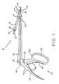
- FIG. 1shows an embodiment of a surgical drill guide assembly 8 according to the invention, which is adapted for use with a cervical spine locking plate.
- a collet 10Telescopically and slideably engaged within collet 10 is a guide sleeve 12.
- a tissue protector 14extends rearwardly from the sleeve 12.
- the collet 10, sleeve 12, and tissue protector 14are adapted to axially receive a drill bit 16, and the guide sleeve 12 is sized to retain the spinning bit 16 in a precise coaxial alignment.
- the collet 10is fixed to a remote rear handle-member 18.
- the handle member 18is pivotably attached to a scissor grip 20 by a handle pin 22.
- handle member 18 and scissor grip 20form a drill guide assembly handle 23, which allows a user to maneuver and use the drill guide assembly.
- the scissor grip 20has an arm 24 that extends to the opposite side of the handle pin 22 from the grip 20 to pivotably attach to an actuation bar 26 at actuation pin 28.
- An end of the bar 26is pivotably attached with the sleeve 12 at sleeve pin 30.
- the entire drill guide assembly in this embodimentforms a four bar linkage.
- the arm 24forces the actuation bar 26 forward.
- This in turnforces the sleeve 12 to slide forward, deeper into collet 10.
- no part of the sleeve 12can slide further forward than the front of the collet 10.
- the scissor grip 20has a forward wall 32 and a rear wall 34 to help the surgeon manually force the sleeve 12 forward or backward by closing or opening the guide sleeve assembly with only one hand.
- leaf springs 36are fastened to the handle member 18 and the scissor grip 20 to further assist rearward motion of the sleeve 12 by biasing the handle 23 towards an open position.
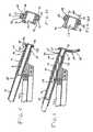
- the collet 10has a radially expandable forward end 40 with a radially expandable means 2.
- the collethas a plurality of fingers 38 that can be spread apart to expand the forward end 40 of the collet 10.
- the collet 10coaxially receives the sleeve 12 about an axis 37. Also, a guide bore 39 extends along axis 37 for guiding a drill bit coaxially therein.
- the forward end 40 of collet 10is preferably comprised of longitudinally extending fingers 38.
- the fingers 38are divided by slots 42 extending longitudinally between adjacent fingers 38.These fingers 38 are resiliently biased inwardly and naturally assume an inward disposition when in a relaxed state and when the sleeve 12 is in the unlocked position, as shown in the figure. In the figure, a portion of the sleeve 12 has been cut away to better illustrate the slots 42.
- the fingers 38form a radially expandable circumferential neck 44.
- neck 44At the back end of and adjacent to neck 44 is a shoulder 46, and at the front end of and adjacent to neck 44 are protrusions that form a radially expandable rim 48.
- These portions of the collet 10, i.e., the neck 44, the shoulder 46, and the rim 44,are preferably a single piece of material of unitary construction, in the interest of minimizing the size of the drill guide that must be inserted into an incision.
- the neck 44 and the rim 48are sized to fit freely through screw holes in a locking plate.
- FIG. 3shows the collet 10 being inserted into a screw hole 64 in a locking plate 56.
- the colletis in its natural, contracted position.
- the collet 10is resiliently biased towards this position, in which the neck 44 has a contracted diameter d1 and the rim has acontracted rim diameter d2.
- the screw hole 64has an inner wall with a hole diameter d3.
- the contracted rim diameter d2is smaller than the hole diameter d3 to permit free and unfettered extraction of the rim 48 from the hole 64.
- the contracted rim diametermeasures between 0,1 mm and 0,3 mm less than the hole diameter d3. More preferably, the rim diameter d2 is 0,2 mm smaller than the hole.
- the contracted rim diameter d2is preferably between 4,2 mm and 4,4 mm in a drill guide that functions with a hole diameter d3 of about 4,5 mm.
- the contracted rim diameteris approximately 95% the size of the hole diameter.
- the contracted rim diameter d2is preferably about between 1 mm and 2 mm larger than the contracted neck diameter d1.
- the rim 48protrudes from the neck 44 by a preferred 1 mm.
- the contracted neck diameter d1is preferably more than 95% as large as the contracted rim diameter d2.
- having a rim 48provides the surgeon with a detectable feel for when the rim 48 has completely passed through the hole 64.
- the rim 48maybe eliminated completely, for instance by reducing the contracted rim diameter d2 to an equal size as the contracted neck diameter d1. These embodiments, though, would lack the signal to the surgeon produced by full passage of the rim 48 through the hole 64.
- the rim 48is rounded in a cross-section taken parallel to axis 37.
- the cross sectionpreferably curves around a radius 49 of about 0,15 mm.
- a surface of the rim 48 disposed adjacent the neck 44is configured at an angle 51 of less than 55° to the neck 44, and most preferably at about 45° thereto. In some embodiments, this angled surface is preferably joined to the neck 44 via a narrow surface 47 of concave radius.
- shoulder 46has a diameter d4 that is greater than the contracted rim diameter d2.
- the shoulder 46has a diameter that is greater than the hole diameter d3 such that the shoulder 46 cannot be inserted therethrough.
- the neck 44is slightly longer than the thickness of the hole wall 65, such that the neck can abut the wall of the locking plate hole and the rim 48 can abut the inside surface of a locking plate 56. In this manner, the drill guide assembly can be secured to the locking plate 56, restricting relative movement.
- the inside of the expandable forward end 40 of the collet 10preferably has a variable inner diameter.
- thefingers 38have a step 50 or a taper, resulting in a smaller inner collet 10 diameter forward of the step 50.
- the guide sleeve 12includes a forward portion 52 that cooperates with the fingers 38 to expand the fingers 38 when the guide sleeve 12 is moved into a locked position.
- the guide sleeve 12is tapered at taper angle 53 to the axis 37 to form a conical forward portion 52.
- the conical section 52 of guide sleeve 12pushes outwardly against the inner surface of the collet 10 as the guide sleeve 12 is moved forward to expand the forward end 40.
- the conical sectionmates with and pushes against the inner collet 10 surface forward of step 50 to push the fingers 38 radially outward.
- the conical section 52allows the fingers 38 to return to a relaxed, contracted position. This allows the collet 10 to be inserted and retracted from the plate hole.
- the taper angle 53is preferably between 3° and 5°, and more preferably about 4°.
- the inner surface of the collet 10 forward of the step 50is also preferably tapered at an angle 55 to axis 37 that is substantially equal to taper angle 53. This range of angles provides a desirable amount of movement of the sleeve 12 within the collet 10 to bias the collet 10 from a contracted position to an expanded position.
- the guide sleeve 12When the surgeon squeezes the handle 23, the guide sleeve 12 is moved forward and the conical section 52 cooperatively forces the inner surface of the collet 10 beyond step 50 and fingers 38 radially outward.
- the forward motion of the guide sleeve 12 towards a forward positionexpands the forward end 40 of the collet 10 to an expanded position.
- the neck 44can be expanded to abut the inner wall of the plate screw hole and the rim 48 is expanded to abut the inner surface of the locking plate.
- the expanded outer diameter d5 of the rim 48is greater than the plate hole diameter d3 so that the guide cannot be retracted from the plate hole, as shown in FIG. 6A.
- FIGs. 5-6Ashow the sleeve 12 in a locked, forward position, and the expandable end 40 in an expanded position and locked to different screw holes of the same predetermined diameter d3.
- screw hole 54 in locking plate 56is disposed at an angle of about 12° to the locking plate's 56 outside surface 58.
- the drill guide assemblyis configured so that when the collet 10 is expanded, as shown, the neck 44 presses outwardly against interior wall 60 of screw hole 54, positively gripping the wall 60.
- the rim 48preferably abuts the back surface of the plate 56 so that the neck positions the guide.
- the shoulder 46on the other hand, preferably does not abut the outside surface 58 of the plate 56. A firm locking against the plate 56 results, and precise co-axial alignment through the center of screw hole 54 is achieved even though the surface area of wall 60 is small.
- the axis of the drill guideis aligned with the axis of the plate screw hole 54.
- the axis of the hole drilled into the bonewill also be aligned with the axis of the plate screw hole 54.
- an anchoring screw inserted into the drilled holewill be centered and aligned with the plate screw hole 54, i . e ., they too will be substantially co-axially aligned.
- rim 48aids in preventing the collet 10 from sliding backwards, out of the hole 54.
- the rim 48is adapted to rest against the far side of the plate 56, near the perimeter of the hole 54. Note that when the drill guide of this embodiment is locked to an angled hole 54, as shown, only a segment of rim 48 may actually contact the back of the plate 56. This small contact surface suffices to retain the collet 10 within the hole 54.
- a gap 62remains between the forwardly facing surface of shoulder 46 and the plate 56. This is because, in the preferred embodiment, the shoulder 46 is not necessary for achieving a proper drill alignment or a secure locking. Consequentially, a surgeon need not press the drill guide against the locking plate 56 to keep the guide properly seated within the hole 54.
- FIGs. 6 and 6Ashow the same embodiment of the invention locked to a screw hole 64 in a different part of locking plate 56.
- Hole 64is perpendicular to the locking plate's 56 surface 66.
- most of the rim 48is in contact with the back of plate 56.
- a gap 62preferably remains between the forwardly facing surface of shoulder 46 and the plate 56.
- the internal diameter of the tissue protector 14is preferably wider than that of the sleeve 12, forming a step 68.
- This step 68may alternatively be formed in a different place along the length of the tissue protector 14 or the sleeve 12.
- Step 68is adapted to stop a surgical drill bit 16 that is inserted through the rearward end of the tissue protector from advancing beyond a predetermined depth. This stopping action occurs when the step 68 contacts a portion 70 of the drill 16 that is wider than the internal diameter of the sleeve 12 or the tissue protector 14 forward of the step 68, as illustrated in FIG. 6.
- the drill bit 16 illustratedhas a safety stop 72 with a wider diameter than the interior of the tissue protector 14.
- the rear 74 of the tissue protector 14also preferably prevents advancement of the drill bit 16 when the tissue-protector rear 74 contacts the bit's 16 safety stop 72.
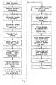
- the flow chart in FIG. 7provides the procedure for implanting a cervical spine locking plate. After making an incision, and measuring the cervical vertebra to be fixed with the plate, a surgeon places a cervical locking plate of a correct estimated length on the vertebral body. The surgeon then bends the plate to contour it to the correct lordotic curvature. Once the plate is properly positioned on the vertebra, it is secured with a temporary fixation pin, which is monitored under lateral imaging.
- the chart in FIG. 8shows the procedure for using the drill guide.
- a surgeoninserts the collet into the plate screw hole and squeezes the handle to slide the sleeve forward, expanding the collet with the conical portion of the sleeve and locking the drill guide to the plate.
- the surgeonthen inserts the drill through the drill guide sleeve, drills the hole, and removes the drill. He or she opens the handle of the drill guide, sliding the sleeve backwards and releasing the collet from the hole, and then freely and unfetteredly removes the guide from the plate.
- the surgeonmay insert the expandable end 40 of the collet 10 into a screw hole in a locking plate 56.
- the surgeonmay grasp and manipulate the plate 56 without an additional plate holder if he or she so desires.
- friction between the forwardly moved conical portion 52 and the inner surface of fingers 38 beyond step 50retains the expandable end 40 of the collet 10 in an expanded, locked position.
- Thisprovides a presently preferred travel of scissor grip 20 required to expand and contract the collet 10.
- the inward bias of fingers 38is selected to produce the desired friction, while allowing operation of the handle 23 with only one hand.
- Alternative taper angles of conical portion 52 and inner finger 38 surfaces, and alternative finger 38 resilienciesmay be chosen according to the purposes of other embodiments.
- the tissue protector 14is preferably sized so that once the plate 56 is properly positioned over the implantation site and the collet 10 is locked to the plate, the tissue protector 14 extends to the outside of the patient's body. As a result, a spinning bit 16 will not laterally reach or harm surrounding tissues that the surgeon does not intend to drill.
- the handle 23is preferably located remotely from the drilling site. This frees space near the plate 56 and permits insertion of the drill guide into narrow incisions.
Landscapes
- Health & Medical Sciences (AREA)
- Surgery (AREA)
- Orthopedic Medicine & Surgery (AREA)
- Life Sciences & Earth Sciences (AREA)
- Biomedical Technology (AREA)
- Molecular Biology (AREA)
- Oral & Maxillofacial Surgery (AREA)
- Engineering & Computer Science (AREA)
- Dentistry (AREA)
- Heart & Thoracic Surgery (AREA)
- Medical Informatics (AREA)
- Nuclear Medicine, Radiotherapy & Molecular Imaging (AREA)
- Animal Behavior & Ethology (AREA)
- General Health & Medical Sciences (AREA)
- Public Health (AREA)
- Veterinary Medicine (AREA)
- Surgical Instruments (AREA)
- Drilling And Boring (AREA)
Abstract
Description
Claims (22)
- Instrumentation for osteofixation comprising:characterized in thata bone plate (56) with plate holes (64) for receiving a bone fastener and having aninner wall (65); anda surgical drill guide comprising a guide member, for guiding a drill bit (16);said surgical drill guide further comprising a hollow collet (10) disposed substantiallycoaxially with the guide member and having a radially expandable forward end (40)with a radially expandable means (2), the means (2) being configured anddimensioned for pressing outwardly against an inner wall (65) of the plate hole (64)in the expanded collet (10) position for releasably securing the drill guide to the plate(56),
said radially expandable means (2) comprises a radially expandable neck (44) andan outwardly projecting rim (48) disposed forward of the neck (44), the rim (48)being configured and dimensioned such that it is freely extractable through the platehole (64) in a contracted collet (10) position and impassable through the plate hole(64) in an expanded collet (10) position. - The instrumentation of claim 1, wherein said radially expandable means (2)comprises a radially expandable neck (44), the neck (44) being configured anddimensioned for pressing outwardly against an inner wall (65) of the plate hole (64) in the expanded collet (10) position for releasably securing the drill guide to the plate(56).
- The instrumentation according to claim 1 or 2, wherein the guide membercomprises a guide sleeve (12) disposed movably axially and telescopically within thecollet (10) and defining a guide bore for axially receiving and guiding a drill bit (16),the guide sleeve (12) having a first position within the collet (10) in which the sleeve(12) biases the collet (10) towards the expanded collet (10) position.
- The instrumentation of claim 1 or 3, wherein the plate holes (64) have apreselected hole diameter d3, and the rim (48) defines an outer rim diameter d2that is smaller than the hole diameter d3 in the contracted collet (10) position andlarger than the hole diameter d3 in the expanded collet (10) position.
- The instrumentation of claim 3 or 4, wherein the collet forward end (40)comprises a plurality of longitudinally extending fingers (38) that define the neck(44) and rim (48) and that are biased radially outwardly when the guide sleeve (12) ismoved into a forward position.
- The instrumentation according to one of the claims 1 to 5, wherein the neck (44)and rim (48) have an axis (37) and the rim (48) has a rounded cross section in a planeextending through the axis (37) for preventing the rim (48) from catching on the plate(56) during extraction of the rim (48) from the plate hole (64).
- The instrumentation of claim 6, wherein the rounded cross-section of the rim(48) has a radius of between 0,1 mm and 0,2 mm.
- The instrumentation according to one of the claims 1 to 7, wherein the rim (48)has a surface substantially adjacent the neck (44) and configured at a first angle (51)thereto of less than 55°.
- The instrumentation of claim 8, wherein the first angle (51) is between 40° and 50°.
- The instrumentation according to one of the claims 3 to 9, wherein the sleeve(12) has a surface tapered inwardly at a second angle (53) of between 3° and 5° forcooperatively biasing the collet (10) towards the expanded collet (10) position whenthe collet (10) is moved forward therein.
- The instrumentation of claim 10, wherein the second angle (53) is between 3,5°4,5°.
- The instrumentation according to one of the claims 1 to 11, wherein theplate holes (64) for receiving abone fastener have an inner wall (65) of a preselected hole diameter d3whereby the rim (48) defines a contracted outer rim diameter d2 that is smaller thanthe hole diameter d3 in an contracted collet (10) position and an expanded outer rimdiameter that is larger than the hole diameter d3 in an expanded collet position suchthat the rim (48) is freely extractable through the plate hole (64) in the contractedcollet (10) position and impassable through the plate hole (64) in the expanded collet (10) position, the neck (44) being configured and dimensioned for pressing outwardlyagainst an inner wall (65) of the plate hole (64) in the expanded collet (10) position forreleasably securing the drill guide to the plate.
- The instrumentation of claim 12, wherein the contracted rim diameter d2 is atleast 0,1 mm smaller than the hole diameter d3.
- The instrumentation of claim 12, wherein the contracted rim diameter d2 is nomore than 0,3 mm smaller than the hole diameter d3.
- The instrumentation of claim 12, wherein the contracted rim diameter d2 isbetween 0,15 mm and 0,25 mm smaller than the hole diameter d3.
- The instrumentation of claim 12, wherein the contracted rim diameter d2 isbetween 90% and 98% of the hole diameter d3.
- The instrumentation according to one of the claims 12 to 16, wherein the rim (48)protrudes radially from the neck (44) by less than 0,1 mm.
- The instrumentation according to one the claims 12 to 17, wherein the neck (44)has a contracted neck diameter d1 in the contracted collet (10) position, thecontracted rim diameter d2 being equal to the contracted neck diameter d1.
- The instrumentation according to one of the claims 12 to 16, wherein the neck (44)has a diameter when the neck (44) is in the contracted collet (10) position that is atleast 95% as large as the contracted rim diameter d2.
- The instrumentation according to one of the claims 1 to 19, wherein the collet(10) is configured for naturally and resiliently biasing the rim (48) to thecontracted collet (10) position.
- The instrumentation according to one of the claims 12 to 20, wherein the collet(10) comprises a shoulder (46) having a diameter larger than the hole diameter d3,the shoulder (46), neck (44), and rim (48) being a single piece of unitaryconstruction.
- The instrumentation according to one of the claims 1 to 21, wherein the boneplate (56) is a locking bone plate with a plurality of plate holes (64) for receivingan anchor screw therethrough.
Applications Claiming Priority (3)
| Application Number | Priority Date | Filing Date | Title |
|---|---|---|---|
| US08/886,547US5851207A (en) | 1997-07-01 | 1997-07-01 | Freely separable surgical drill guide and plate |
| US886547 | 1997-07-01 | ||
| PCT/EP1998/003778WO1999001072A1 (en) | 1997-07-01 | 1998-06-20 | Freely separable surgical drill guide and plate |
Publications (2)
| Publication Number | Publication Date |
|---|---|
| EP0993275A1 EP0993275A1 (en) | 2000-04-19 |
| EP0993275B1true EP0993275B1 (en) | 2004-04-07 |
Family
ID=25389237
Family Applications (1)
| Application Number | Title | Priority Date | Filing Date |
|---|---|---|---|
| EP98937525AExpired - LifetimeEP0993275B1 (en) | 1997-07-01 | 1998-06-20 | Freely separable surgical drill guide and plate |
Country Status (10)
| Country | Link |
|---|---|
| US (2) | US5851207A (en) |
| EP (1) | EP0993275B1 (en) |
| JP (1) | JP3996211B2 (en) |
| CN (1) | CN1155341C (en) |
| AT (1) | ATE263510T1 (en) |
| AU (1) | AU719525B2 (en) |
| DE (1) | DE69823030T2 (en) |
| ES (1) | ES2215316T3 (en) |
| WO (1) | WO1999001072A1 (en) |
| ZA (1) | ZA985284B (en) |
Families Citing this family (158)
| Publication number | Priority date | Publication date | Assignee | Title |
|---|---|---|---|---|
| US20040220571A1 (en)* | 1998-04-30 | 2004-11-04 | Richard Assaker | Bone plate assembly |
| US6533786B1 (en)* | 1999-10-13 | 2003-03-18 | Sdgi Holdings, Inc. | Anterior cervical plating system |
| FR2778088B1 (en)* | 1998-04-30 | 2000-09-08 | Materiel Orthopedique En Abreg | ANTERIOR IMPLANT, PARTICULARLY FOR THE CERVICAL RACHIS |
| US6159179A (en) | 1999-03-12 | 2000-12-12 | Simonson; Robert E. | Cannula and sizing and insertion method |
| US6692503B2 (en)* | 1999-10-13 | 2004-02-17 | Sdgi Holdings, Inc | System and method for securing a plate to the spinal column |
| US7695502B2 (en) | 2000-02-01 | 2010-04-13 | Depuy Products, Inc. | Bone stabilization system including plate having fixed-angle holes together with unidirectional locking screws and surgeon-directed locking screws |
| US7857838B2 (en) | 2003-03-27 | 2010-12-28 | Depuy Products, Inc. | Anatomical distal radius fracture fixation plate |
| US20040153073A1 (en) | 2000-02-01 | 2004-08-05 | Hand Innovations, Inc. | Orthopedic fixation system including plate element with threaded holes having divergent axes |
| US6767351B2 (en) | 2000-02-01 | 2004-07-27 | Hand Innovations, Inc. | Fixation system with multidirectional stabilization pegs |
| US6706046B2 (en) | 2000-02-01 | 2004-03-16 | Hand Innovations, Inc. | Intramedullary fixation device for metaphyseal long bone fractures and methods of using the same |
| US6210415B1 (en)* | 2000-02-18 | 2001-04-03 | Lab Engineering & Manufacturing, Inc. | Surgical drill guide |
| US6725080B2 (en) | 2000-03-01 | 2004-04-20 | Surgical Navigation Technologies, Inc. | Multiple cannula image guided tool for image guided procedures |
| US6712856B1 (en) | 2000-03-17 | 2004-03-30 | Kinamed, Inc. | Custom replacement device for resurfacing a femur and method of making the same |
| US6379364B1 (en) | 2000-04-28 | 2002-04-30 | Synthes (Usa) | Dual drill guide for a locking bone plate |
| US6342057B1 (en) | 2000-04-28 | 2002-01-29 | Synthes (Usa) | Remotely aligned surgical drill guide |
| AU2001280476B2 (en) | 2000-06-30 | 2005-11-24 | Stephen Ritland | Polyaxial connection device and method |
| WO2002024081A1 (en) | 2000-09-22 | 2002-03-28 | Codman & Shurtleff, Inc. | Self centering bone drill |
| US7166073B2 (en) | 2000-09-29 | 2007-01-23 | Stephen Ritland | Method and device for microsurgical intermuscular spinal surgery |
| US6692434B2 (en) | 2000-09-29 | 2004-02-17 | Stephen Ritland | Method and device for retractor for microsurgical intermuscular lumbar arthrodesis |
| US6929606B2 (en) | 2001-01-29 | 2005-08-16 | Depuy Spine, Inc. | Retractor and method for spinal pedicle screw placement |
| WO2002060330A1 (en)* | 2001-01-29 | 2002-08-08 | Stephen Ritland | Retractor and method for spinal pedicle screw placement |
| JP4180506B2 (en)* | 2001-06-27 | 2008-11-12 | デピュイ・プロダクツ・インコーポレイテッド | Minimally invasive orthopedic device and method |
| DE60238997D1 (en) | 2001-09-28 | 2011-03-03 | Stephen Ritland | CHROME OR HOOKS |
| US7008431B2 (en)* | 2001-10-30 | 2006-03-07 | Depuy Spine, Inc. | Configured and sized cannula |
| US7824410B2 (en) | 2001-10-30 | 2010-11-02 | Depuy Spine, Inc. | Instruments and methods for minimally invasive spine surgery |
| US7094242B2 (en)* | 2001-10-31 | 2006-08-22 | K2M, Inc. | Polyaxial drill guide |
| WO2003057051A1 (en)* | 2002-01-09 | 2003-07-17 | Synthes Ag Chur | Device for drilling or for inserting implants |
| ATE476930T1 (en) | 2002-02-20 | 2010-08-15 | Stephen Ritland | DEVICE FOR CONNECTING HAND SCREWS |
| US6913463B2 (en) | 2002-02-20 | 2005-07-05 | Gordon D. Blacklock | Drilling guide for dental implantation |
| US20030187443A1 (en)* | 2002-03-27 | 2003-10-02 | Carl Lauryssen | Anterior bone plate system and method of use |
| US6966910B2 (en) | 2002-04-05 | 2005-11-22 | Stephen Ritland | Dynamic fixation device and method of use |
| ATE552789T1 (en) | 2002-05-08 | 2012-04-15 | Stephen Ritland | DYNAMIC FIXATION DEVICE |
| US7011665B2 (en)* | 2002-07-22 | 2006-03-14 | Sdgi Holdings, Inc. | Guide assembly for engaging a bone plate to a bony segment |
| US7862597B2 (en)* | 2002-08-22 | 2011-01-04 | Warsaw Orthopedic, Inc. | System for stabilizing a portion of the spine |
| US7625378B2 (en)* | 2002-09-30 | 2009-12-01 | Warsaw Orthopedic, Inc. | Devices and methods for securing a bone plate to a bony segment |
| US7780664B2 (en) | 2002-12-10 | 2010-08-24 | Depuy Products, Inc. | Endosteal nail |
| US7914561B2 (en) | 2002-12-31 | 2011-03-29 | Depuy Spine, Inc. | Resilient bone plate and screw system allowing bi-directional assembly |
| US7175624B2 (en) | 2002-12-31 | 2007-02-13 | Depuy Spine, Inc. | Bone plate and screw system allowing bi-directional assembly |
| US7048739B2 (en)* | 2002-12-31 | 2006-05-23 | Depuy Spine, Inc. | Bone plate and resilient screw system allowing bi-directional assembly |
| US7341591B2 (en) | 2003-01-30 | 2008-03-11 | Depuy Spine, Inc. | Anterior buttress staple |
| US20040152955A1 (en)* | 2003-02-04 | 2004-08-05 | Mcginley Shawn E. | Guidance system for rotary surgical instrument |
| US20040171930A1 (en)* | 2003-02-04 | 2004-09-02 | Zimmer Technology, Inc. | Guidance system for rotary surgical instrument |
| EP1596738A4 (en) | 2003-02-25 | 2010-01-20 | Stephen Ritland | Adjustable rod and connector device and method of use |
| DE10310978B3 (en)* | 2003-03-06 | 2004-08-26 | Karl Storz Gmbh & Co. Kg | Surgical instrument for creating operating field for repair work on fractured human jaw uses endoscope with shaft passing through small incision in cheek to flat plate fixed to jaw |
| US6960216B2 (en)* | 2003-03-21 | 2005-11-01 | Depuy Acromed, Inc. | Modular drill guide |
| BRPI0408769A (en)* | 2003-03-26 | 2006-03-28 | Swiss Orthopedic Solutions Sa | lock bone plate |
| US7905883B2 (en)* | 2003-03-26 | 2011-03-15 | Greatbatch Medical S.A. | Locking triple pelvic osteotomy plate and method of use |
| US7722653B2 (en)* | 2003-03-26 | 2010-05-25 | Greatbatch Medical S.A. | Locking bone plate |
| US7935123B2 (en)* | 2003-04-09 | 2011-05-03 | Depuy Acromed, Inc. | Drill guide with alignment feature |
| US7909829B2 (en)* | 2003-06-27 | 2011-03-22 | Depuy Spine, Inc. | Tissue retractor and drill guide |
| US7776047B2 (en) | 2003-04-09 | 2010-08-17 | Depuy Spine, Inc. | Guide for spinal tools, implants, and devices |
| US7416553B2 (en) | 2003-04-09 | 2008-08-26 | Depuy Acromed, Inc. | Drill guide and plate inserter |
| US20040210232A1 (en)* | 2003-04-09 | 2004-10-21 | Tushar Patel | Guide device and plate inserter |
| WO2004110247A2 (en) | 2003-05-22 | 2004-12-23 | Stephen Ritland | Intermuscular guide for retractor insertion and method of use |
| US7909848B2 (en)* | 2003-06-27 | 2011-03-22 | Depuy Spine, Inc. | Tissue retractor and guide device |
| US7731721B2 (en) | 2003-07-16 | 2010-06-08 | Synthes Usa, Llc | Plating system with multiple function drill guide |
| KR20060123057A (en)* | 2003-08-01 | 2006-12-01 | 신세스 게엠바하 | Drill guide assembly for bone fixation |
| US7625375B2 (en) | 2003-08-06 | 2009-12-01 | Warsaw Orthopedic, Inc. | Systems and techniques for stabilizing the spine and placing stabilization systems |
| US7357804B2 (en) | 2003-08-13 | 2008-04-15 | Synthes (U.S.A.) | Quick-release drill-guide assembly for bone-plate |
| US7909860B2 (en) | 2003-09-03 | 2011-03-22 | Synthes Usa, Llc | Bone plate with captive clips |
| US20050049595A1 (en) | 2003-09-03 | 2005-03-03 | Suh Sean S. | Track-plate carriage system |
| US7141074B2 (en)* | 2003-09-17 | 2006-11-28 | Depuy Spine, Inc. | Variable depth drill with self-centering sleeve |
| WO2005041752A2 (en)* | 2003-10-20 | 2005-05-12 | Blackstone Medical, Inc. | Bone plate and method for using bone plate |
| US7648506B2 (en) | 2003-12-16 | 2010-01-19 | Depuy Acromed, Inc. | Pivoting implant holder |
| US7648507B2 (en)* | 2003-12-16 | 2010-01-19 | Depuy Acromed, Inc. | Pivoting implant holder |
| US8123757B2 (en) | 2003-12-31 | 2012-02-28 | Depuy Spine, Inc. | Inserter instrument and implant clip |
| US7488326B2 (en)* | 2004-01-02 | 2009-02-10 | Zimmer Technology, Inc. | Combination targeting guide and driver instrument for use in orthopaedic surgical procedures |
| USD536453S1 (en) | 2004-03-25 | 2007-02-06 | Precimed S.A. | Bone plate |
| WO2006091827A2 (en) | 2005-02-25 | 2006-08-31 | Regents Of The University Of California | Device and template for canine humeral slide osteotomy |
| US20080045960A1 (en)* | 2004-03-25 | 2008-02-21 | Bruecker Kenneth | Locking tpo plate and method of use |
| US7488327B2 (en)* | 2004-04-12 | 2009-02-10 | Synthes (U.S.A.) | Free hand drill guide |
| US7033363B2 (en) | 2004-05-19 | 2006-04-25 | Sean Powell | Snap-lock for drill sleeve |
| US7909843B2 (en) | 2004-06-30 | 2011-03-22 | Thompson Surgical Instruments, Inc. | Elongateable surgical port and dilator |
| US7455639B2 (en) | 2004-09-20 | 2008-11-25 | Stephen Ritland | Opposing parallel bladed retractor and method of use |
| US20060106387A1 (en)* | 2004-11-16 | 2006-05-18 | Depuy Spine, Inc. | Spinal plate system and method of use |
| US7575579B2 (en)* | 2004-11-18 | 2009-08-18 | Union Surgical, Llc | Drill guide tissue protector |
| US7621916B2 (en)* | 2004-11-18 | 2009-11-24 | Depuy Spine, Inc. | Cervical bone preparation tool and implant guide systems |
| US7166111B2 (en)* | 2004-12-08 | 2007-01-23 | Depuy Spine, Inc. | Spinal plate and drill guide |
| US7931678B2 (en) | 2004-12-08 | 2011-04-26 | Depuy Spine, Inc. | Hybrid spinal plates |
| US8172886B2 (en) | 2004-12-14 | 2012-05-08 | Depuy Products, Inc. | Bone plate with pre-assembled drill guide tips |
| US7771433B2 (en)* | 2004-12-14 | 2010-08-10 | Depuy Products, Inc. | Bone fracture fixation plate shaping system |
| US20060155284A1 (en)* | 2005-01-07 | 2006-07-13 | Depuy Spine Sarl | Occipital plate and guide systems |
| US8109934B2 (en)* | 2005-02-10 | 2012-02-07 | Zimmer Spine, Inc. | All through one drill guide for cervical plating |
| US20060235403A1 (en) | 2005-03-17 | 2006-10-19 | Jason Blain | Flanged interbody fusion device with locking plate |
| US8215957B2 (en)* | 2005-05-12 | 2012-07-10 | Robert Shelton | Dental implant placement locator and method of use |
| ES2443193T3 (en) | 2005-06-01 | 2014-02-18 | Stryker Trauma Sa | Quick coupling guide for elements of an external bone fixation system |
| US8177823B2 (en)* | 2005-06-30 | 2012-05-15 | Depuy Spine Sarl | Orthopedic clamping hook assembly |
| JP4988735B2 (en) | 2005-07-19 | 2012-08-01 | リットランド、ステファン | Rod extension for elongating fusion structures |
| ES2346670T3 (en)* | 2005-08-15 | 2010-10-19 | Synthes Gmbh | OSTEOSYNTHESIS DEVICE. |
| US7905909B2 (en) | 2005-09-19 | 2011-03-15 | Depuy Products, Inc. | Bone stabilization system including multi-directional threaded fixation element |
| US7753914B2 (en)* | 2005-09-29 | 2010-07-13 | Depuy Products, Inc. | Orthopaedic gage, kit and associated method |
| US20070088364A1 (en)* | 2005-09-29 | 2007-04-19 | Ruhling Marc E | Trauma gage, kit and associated method |
| US20070093848A1 (en)* | 2005-09-29 | 2007-04-26 | Peter Harris | Cervical drill guide apparatus |
| US7887595B1 (en) | 2005-12-05 | 2011-02-15 | Nuvasive, Inc. | Methods and apparatus for spinal fusion |
| US9119677B2 (en) | 2005-12-09 | 2015-09-01 | DePuy Synthes Products, Inc. | Spinal plate and drill guide |
| WO2007130699A2 (en)* | 2006-01-13 | 2007-11-15 | Clifford Tribus | Spine reduction and stabilization device |
| US7867279B2 (en) | 2006-01-23 | 2011-01-11 | Depuy Spine, Inc. | Intervertebral disc prosthesis |
| US7473255B2 (en)* | 2006-02-08 | 2009-01-06 | Synthes (U.S.A.) | Transbuccal plate holding cannula |
| US20070239153A1 (en)* | 2006-02-22 | 2007-10-11 | Hodorek Robert A | Computer assisted surgery system using alternative energy technology |
| US20070233108A1 (en)* | 2006-03-15 | 2007-10-04 | Stalcup Gregory C | Spine fixation device |
| US7740634B2 (en)* | 2006-03-20 | 2010-06-22 | Depuy Products, Inc. | Method of bone plate shaping |
| US7935126B2 (en) | 2006-03-20 | 2011-05-03 | Depuy Products, Inc. | Bone plate shaping system |
| US20070274905A1 (en)* | 2006-05-24 | 2007-11-29 | Water To Gas Lp | Thermal disassociation of water |
| US7959564B2 (en)* | 2006-07-08 | 2011-06-14 | Stephen Ritland | Pedicle seeker and retractor, and methods of use |
| US8114162B1 (en) | 2006-08-09 | 2012-02-14 | Nuvasive, Inc. | Spinal fusion implant and related methods |
| USD708747S1 (en) | 2006-09-25 | 2014-07-08 | Nuvasive, Inc. | Spinal fusion implant |
| US8282642B2 (en)* | 2006-09-26 | 2012-10-09 | K2M, Inc. | Cervical drill guide apparatus |
| US20080132900A1 (en)* | 2006-11-13 | 2008-06-05 | Stryker Trauma Gmbh | Drill alignment assembly for a bone plate using tissue protection sleeves that are fixed in the bone plate |
| US8579910B2 (en)* | 2007-05-18 | 2013-11-12 | DePuy Synthes Products, LLC | Insertion blade assembly and method of use |
| US8172854B2 (en)* | 2007-07-19 | 2012-05-08 | Spinal Elements, Inc. | Attachable instrument guide with detachable handle |
| US8709054B2 (en) | 2007-08-07 | 2014-04-29 | Transcorp, Inc. | Implantable vertebral frame systems and related methods for spinal repair |
| US8628530B2 (en)* | 2007-08-16 | 2014-01-14 | Nutek Orthopedics, Inc. | External fixation apparatus with angularly adjustable drill guiding and pin clamping means |
| US8430882B2 (en)* | 2007-09-13 | 2013-04-30 | Transcorp, Inc. | Transcorporeal spinal decompression and repair systems and related methods |
| WO2009036367A1 (en) | 2007-09-13 | 2009-03-19 | Transcorp, Inc. | Transcorporeal spinal decompression and repair system and related method |
| US20090088604A1 (en)* | 2007-09-28 | 2009-04-02 | David Lowry | Vertebrally-mounted tissue retractor and method for use in spinal surgery |
| EP2227181A1 (en)* | 2007-11-27 | 2010-09-15 | Transcorp, Inc. | Methods and systems for repairing an intervertebral disc using a transcorporal approach |
| EP2072016B1 (en)* | 2007-12-17 | 2012-10-03 | Stryker Leibinger GmbH & Co. KG | Bone plate instrument and method |
| US8496665B2 (en)* | 2008-02-13 | 2013-07-30 | Biomet C.V. | Drill sleeve |
| US8080045B2 (en)* | 2008-04-08 | 2011-12-20 | Wotton Iii Harold M | Bone clamp |
| US8337533B2 (en)* | 2008-06-20 | 2012-12-25 | Osteomed Llc | Locking plate benders |
| ES2533802T3 (en)* | 2008-09-02 | 2015-04-14 | Stryker Trauma Sa | Locator device for a bone plate |
| US8425573B2 (en) | 2008-10-24 | 2013-04-23 | The Cleveland Clinic Foundation | Method and system for attaching a plate to a bone |
| US20100130983A1 (en)* | 2008-11-26 | 2010-05-27 | Osteomed L.P. | Drill Guide for Angled Trajectories |
| US8323292B2 (en) | 2008-12-15 | 2012-12-04 | Spinecore, Inc. | Adjustable pin drill guide and methods therefor |
| US20100217399A1 (en)* | 2009-02-22 | 2010-08-26 | Groh Gordon I | Base plate system for shoulder arthroplasty and method of using the same |
| US9220547B2 (en) | 2009-03-27 | 2015-12-29 | Spinal Elements, Inc. | Flanged interbody fusion device |
| US8906033B2 (en) | 2009-03-30 | 2014-12-09 | DePuy Synthes Products, LLC | Cervical motion disc inserter |
| US8308732B2 (en)* | 2009-04-10 | 2012-11-13 | Arthrex, Inc. | Parallel drill guide |
| US8652183B1 (en)* | 2009-07-07 | 2014-02-18 | Mari S Truman | Multi-angle orthopedic expansion head fastener |
| CN102188273B (en)* | 2010-03-02 | 2013-03-27 | 上海微创骨科医疗科技有限公司 | Limit adjusting device |
| US8425569B2 (en) | 2010-05-19 | 2013-04-23 | Transcorp, Inc. | Implantable vertebral frame systems and related methods for spinal repair |
| WO2012173890A2 (en) | 2011-06-16 | 2012-12-20 | Smith & Nephew, Inc. | Surgical alignment using references |
| US11123117B1 (en) | 2011-11-01 | 2021-09-21 | Nuvasive, Inc. | Surgical fixation system and related methods |
| EP2806808A4 (en)* | 2012-01-26 | 2015-11-04 | Smith & Nephew Inc | Implant fixation member holder |
| US8986354B2 (en) | 2012-02-14 | 2015-03-24 | Zavation Llc | Surgical kit for spinal surgery |
| US9050151B2 (en) | 2012-03-06 | 2015-06-09 | Stryker Trauma Sa | Bone plate and aiming block |
| JP6046396B2 (en)* | 2012-07-02 | 2016-12-14 | 富士重工業株式会社 | Drill driving device and drill driving method |
| US11007063B2 (en) | 2013-03-11 | 2021-05-18 | Catalyst Orthoscience Inc. | Offset reamers |
| US10973646B2 (en) | 2013-03-11 | 2021-04-13 | Catalyst Orthoscience Inc. | Stabilized drill guide |
| US20170319348A1 (en) | 2015-08-10 | 2017-11-09 | Catalyst Orthoscience Inc. | Arthroplasty prostheses with multi-axis fixation |
| DE102013104887B4 (en)* | 2013-05-13 | 2021-03-18 | Aap Implantate Ag | Osteosynthesis plate and segment for an osteosynthesis plate |
| US9750512B2 (en) | 2013-10-21 | 2017-09-05 | Zimmer Spine, Inc. | Drill guide for installing a bone plate |
| AU2016212009C1 (en) | 2015-01-27 | 2021-02-25 | Spinal Elements, Inc. | Facet joint implant |
| US10064668B2 (en)* | 2015-02-13 | 2018-09-04 | Kls-Martin, L.P. | Bone plate locking cannula and drill guide assembly |
| US10238439B2 (en)* | 2015-04-24 | 2019-03-26 | Meditech Spine, Llc | Anterior spinal bone plate holding system and method |
| US10327787B2 (en) | 2015-12-28 | 2019-06-25 | Nuvasive, Inc | Adjustable depth drill guide |
| EP3284442B1 (en)* | 2016-07-27 | 2023-07-19 | Catalyst OrthoScience Inc. | Stabilized drill guide |
| US9931702B2 (en)* | 2016-09-01 | 2018-04-03 | The Boeing Company | Locking drill bushing |
| US11026669B2 (en)* | 2017-07-13 | 2021-06-08 | Medtronic Vascular, Inc. | Collapsible dilator |
| US11058437B2 (en) | 2018-03-29 | 2021-07-13 | Zimmer Biomet Spine, Inc. | Systems and methods for pedicle screw implantation using flexible drill bit |
| US11141172B2 (en) | 2018-04-11 | 2021-10-12 | Globus Medical, Inc. | Method and apparatus for locking a drill guide in a polyaxial hole |
| AU2019342137A1 (en) | 2018-09-20 | 2021-03-25 | Spinal Elements, Inc. | Spinal implant device |
| US12213682B2 (en) | 2019-12-27 | 2025-02-04 | Integrity Implants Inc. | Anti-skive bone drill |
| US11911284B2 (en) | 2020-11-19 | 2024-02-27 | Spinal Elements, Inc. | Curved expandable interbody devices and deployment tools |
| WO2022133456A1 (en) | 2020-12-17 | 2022-06-23 | Spinal Elements, Inc. | Spinal implant device |
| US11464526B2 (en)* | 2021-01-15 | 2022-10-11 | DePuy Synthes Products, Inc. | Self-orienting drill sleeve |
| US12408959B2 (en)* | 2022-07-13 | 2025-09-09 | Globus Medical, Inc. | Plate inserter system and method |
| CN117137602A (en)* | 2023-08-15 | 2023-12-01 | 上海三友医疗器械股份有限公司 | Cervical bone plate and plate guide for ACAF surgery |
Family Cites Families (39)
| Publication number | Priority date | Publication date | Assignee | Title |
|---|---|---|---|---|
| US1831813A (en)* | 1928-07-02 | 1931-11-17 | Independent Pneumatic Tool Co | Attachment for drills |
| US2248054A (en)* | 1939-06-07 | 1941-07-08 | Becker Joseph | Screw driver |
| US2494229A (en)* | 1946-07-08 | 1950-01-10 | John G Collison | Bone surgery |
| US2490364A (en)* | 1948-02-27 | 1949-12-06 | Herman H Livingston | Bone pin |
| US2839953A (en)* | 1955-10-24 | 1958-06-24 | Boeing Co | Drill motor collet mounts |
| US2935905A (en)* | 1956-12-10 | 1960-05-10 | Winslow Product Engineering Co | Collet foot attachment for pneumatic power drill |
| DE2109162B1 (en)* | 1971-02-26 | 1972-05-25 | Fischer Artur | Sleeve-shaped support element for long bone fractures |
| GB1571713A (en) | 1976-04-21 | 1980-07-16 | Gil J L | Apparatus for use in the treatment of bone fractures |
| US4341206A (en) | 1978-12-19 | 1982-07-27 | Synthes Ag | Device for producing a hole in a bone |
| IE810323L (en) | 1980-02-19 | 1981-08-19 | Nat Res Dev | External fixation devices for orthopaedic fractures |
| US4312337A (en)* | 1980-09-08 | 1982-01-26 | Donohue Brian T | Cannula and drill guide apparatus |
| US4465065A (en) | 1983-01-07 | 1984-08-14 | Yechiel Gotfried | Surgical device for connection of fractured bones |
| US4537185A (en)* | 1983-06-10 | 1985-08-27 | Denis P. Stednitz | Cannulated fixation screw |
| US4570624A (en) | 1983-08-10 | 1986-02-18 | Henry Ford Hospital | Universal guide for inserting parallel pins |
| US4599999A (en) | 1984-06-11 | 1986-07-15 | Synthes Ag | Drill guide for use with surgical compression plates |
| CN1006954B (en)* | 1985-03-11 | 1990-02-28 | 阿图尔·费希尔 | Fastening elements for osteosynthesis |
| EP0209685A3 (en)* | 1985-07-12 | 1988-11-09 | Fischerwerke Arthur Fischer GmbH & Co. KG | Fixation element for osteosynthesis |
| DE3601715A1 (en)* | 1986-01-22 | 1987-07-23 | Heinl Thomas | SURGICAL INSTRUMENT SET FOR CONNECTING BONE FRAGMENTS |
| DD258359A5 (en) | 1986-04-01 | 1988-07-20 | Stabilizer for adjusting the drilling when drilling holes in the bone | |
| EP0248103A1 (en)* | 1986-06-06 | 1987-12-09 | Hellige GmbH | Adapter for exchangeably implanting bio-sensors in the skull bone |
| US5151103A (en)* | 1987-11-03 | 1992-09-29 | Synthes (U.S.A.) | Point contact bone compression plate |
| ES1011373Y (en)* | 1989-08-28 | 1990-09-01 | Sanchez Perez Francisco | APPARATUS FOR THE PLACEMENT OF ID SEALS. |
| DD293261A5 (en) | 1990-04-06 | 1991-08-29 | Veb Komb. Medizin- U. Labortechnik,De | DRILLING FOR PLATE FIXATEUR |
| CH681421A5 (en) | 1990-06-06 | 1993-03-31 | Synthes Ag | |
| US5133720A (en)* | 1990-07-13 | 1992-07-28 | Greenberg Alex M | Surgical drill guide and retractor |
| US5026376A (en)* | 1990-07-13 | 1991-06-25 | Greenberg Alex M | Surgical drill guide and retractor |
| US5147367A (en)* | 1991-02-22 | 1992-09-15 | Ellis Alfred B | Drill pin guide and method for orthopedic surgery |
| GB9221257D0 (en)* | 1992-10-09 | 1992-11-25 | Minnesota Mining & Mfg | Glenoid alignment guide |
| US5364399A (en)* | 1993-02-05 | 1994-11-15 | Danek Medical, Inc. | Anterior cervical plating system |
| US5423826A (en)* | 1993-02-05 | 1995-06-13 | Danek Medical, Inc. | Anterior cervical plate holder/drill guide and method of use |
| IL105183A (en) | 1993-03-28 | 1996-07-23 | Yehiel Gotfried | Surgical device for connection of fractured bones |
| ES2121964T3 (en) | 1993-09-09 | 1998-12-16 | Mecaplast Sam | DEVICE FOR OPENING A DUCT AND APPLICATION OF SUCH DEVICE. |
| US5425490A (en)* | 1994-01-18 | 1995-06-20 | Goble; E. Marlowe | Instrument with dual holding feature |
| US5489210A (en)* | 1994-05-13 | 1996-02-06 | Hanosh; Frederick N. | Expanding dental implant and method for its use |
| AU3207895A (en) | 1994-08-23 | 1996-03-14 | Spine-Tech, Inc. | Cervical spine stabilization system |
| US5782919A (en)* | 1995-03-27 | 1998-07-21 | Sdgi Holdings, Inc. | Interbody fusion device and method for restoration of normal spinal anatomy |
| US5520690A (en)* | 1995-04-13 | 1996-05-28 | Errico; Joseph P. | Anterior spinal polyaxial locking screw plate assembly |
| FR2738475B1 (en)* | 1995-09-11 | 1998-01-16 | Landanger Landos | PLIERS FOR PRESENTING MAXILLO-FACIAL OSTEOSYNTHESIS PLATES |
| US5755721A (en)* | 1996-03-13 | 1998-05-26 | Synthes | Plate holding drill guide and trocar and method of holding a plate |
- 1997
- 1997-07-01USUS08/886,547patent/US5851207A/ennot_activeCeased
- 1998
- 1998-06-18ZAZA985284Apatent/ZA985284B/enunknown
- 1998-06-20ATAT98937525Tpatent/ATE263510T1/ennot_activeIP Right Cessation
- 1998-06-20EPEP98937525Apatent/EP0993275B1/ennot_activeExpired - Lifetime
- 1998-06-20ESES98937525Tpatent/ES2215316T3/ennot_activeExpired - Lifetime
- 1998-06-20CNCNB98806748XApatent/CN1155341C/ennot_activeExpired - Fee Related
- 1998-06-20WOPCT/EP1998/003778patent/WO1999001072A1/enactiveIP Right Grant
- 1998-06-20AUAU86285/98Apatent/AU719525B2/ennot_activeCeased
- 1998-06-20DEDE69823030Tpatent/DE69823030T2/ennot_activeExpired - Lifetime
- 1998-06-20JPJP50624299Apatent/JP3996211B2/ennot_activeExpired - Fee Related
- 2000
- 2000-10-10USUS09/686,198patent/USRE38684E1/ennot_activeExpired - Lifetime
Also Published As
| Publication number | Publication date |
|---|---|
| DE69823030T2 (en) | 2005-03-10 |
| AU719525B2 (en) | 2000-05-11 |
| JP2002507140A (en) | 2002-03-05 |
| EP0993275A1 (en) | 2000-04-19 |
| US5851207A (en) | 1998-12-22 |
| AU8628598A (en) | 1999-01-25 |
| CN1155341C (en) | 2004-06-30 |
| USRE38684E1 (en) | 2005-01-04 |
| ES2215316T3 (en) | 2004-10-01 |
| ATE263510T1 (en) | 2004-04-15 |
| CN1261773A (en) | 2000-08-02 |
| DE69823030D1 (en) | 2004-05-13 |
| JP3996211B2 (en) | 2007-10-24 |
| WO1999001072A1 (en) | 1999-01-14 |
| ZA985284B (en) | 1999-01-11 |
Similar Documents
| Publication | Publication Date | Title |
|---|---|---|
| EP0993275B1 (en) | Freely separable surgical drill guide and plate | |
| EP1737356B1 (en) | Free hand drill guide | |
| US7357804B2 (en) | Quick-release drill-guide assembly for bone-plate | |
| EP1651122B1 (en) | Plating system with multiple function drill guide | |
| US7985229B2 (en) | Drill guide assembly for a bone fixation device | |
| JP4602338B2 (en) | Intramedullary nail assembly | |
| US6106528A (en) | Modular intramedullary fixation system and insertion instrumentation | |
| US5484440A (en) | Bone screw and screwdriver | |
| US6342057B1 (en) | Remotely aligned surgical drill guide | |
| EP1439799B1 (en) | Expanding ligament graft fixation system | |
| EP4252682B1 (en) | A femoral nail and instrumentation system | |
| US5993450A (en) | Osteosynthesis ring usable in combination with a pin or a screw, and compressing device therefore | |
| US20100049220A1 (en) | Insertion system for implanting a medical device and surgical methods | |
| US12357473B2 (en) | Laminoplasty implant systems and methods |
Legal Events
| Date | Code | Title | Description |
|---|---|---|---|
| PUAI | Public reference made under article 153(3) epc to a published international application that has entered the european phase | Free format text:ORIGINAL CODE: 0009012 | |
| 17P | Request for examination filed | Effective date:19991119 | |
| AK | Designated contracting states | Kind code of ref document:A1 Designated state(s):AT CH DE ES GB IT LI NL SE | |
| RIN1 | Information on inventor provided before grant (corrected) | Inventor name:CESARONE, MORRIX, DANIEL | |
| GRAP | Despatch of communication of intention to grant a patent | Free format text:ORIGINAL CODE: EPIDOSNIGR1 | |
| GRAS | Grant fee paid | Free format text:ORIGINAL CODE: EPIDOSNIGR3 | |
| GRAA | (expected) grant | Free format text:ORIGINAL CODE: 0009210 | |
| AK | Designated contracting states | Kind code of ref document:B1 Designated state(s):AT CH DE ES GB IT LI NL SE | |
| REG | Reference to a national code | Ref country code:GB Ref legal event code:FG4D | |
| REG | Reference to a national code | Ref country code:CH Ref legal event code:NV Representative=s name:DR. LUSUARDI AG Ref country code:CH Ref legal event code:EP | |
| PGFP | Annual fee paid to national office [announced via postgrant information from national office to epo] | Ref country code:NL Payment date:20040512 Year of fee payment:7 | |
| REF | Corresponds to: | Ref document number:69823030 Country of ref document:DE Date of ref document:20040513 Kind code of ref document:P | |
| REG | Reference to a national code | Ref country code:SE Ref legal event code:TRGR | |
| REG | Reference to a national code | Ref country code:ES Ref legal event code:FG2A Ref document number:2215316 Country of ref document:ES Kind code of ref document:T3 | |
| PLBE | No opposition filed within time limit | Free format text:ORIGINAL CODE: 0009261 | |
| STAA | Information on the status of an ep patent application or granted ep patent | Free format text:STATUS: NO OPPOSITION FILED WITHIN TIME LIMIT | |
| 26N | No opposition filed | Effective date:20050110 | |
| PG25 | Lapsed in a contracting state [announced via postgrant information from national office to epo] | Ref country code:NL Free format text:LAPSE BECAUSE OF NON-PAYMENT OF DUE FEES Effective date:20060101 | |
| NLV4 | Nl: lapsed or anulled due to non-payment of the annual fee | Effective date:20060101 | |
| REG | Reference to a national code | Ref country code:CH Ref legal event code:PUE Owner name:SYNTHES GMBH Free format text:SYNTHES AG CHUR#GRABENSTRASSE 15#7002 CHUR (CH) -TRANSFER TO- SYNTHES GMBH#EIMATTSTRASSE 3#4436 OBERDORF (CH) | |
| REG | Reference to a national code | Ref country code:GB Ref legal event code:732E | |
| PGFP | Annual fee paid to national office [announced via postgrant information from national office to epo] | Ref country code:AT Payment date:20100610 Year of fee payment:13 | |
| PGFP | Annual fee paid to national office [announced via postgrant information from national office to epo] | Ref country code:SE Payment date:20100609 Year of fee payment:13 | |
| REG | Reference to a national code | Ref country code:SE Ref legal event code:EUG | |
| PG25 | Lapsed in a contracting state [announced via postgrant information from national office to epo] | Ref country code:AT Free format text:LAPSE BECAUSE OF NON-PAYMENT OF DUE FEES Effective date:20110620 | |
| REG | Reference to a national code | Ref country code:AT Ref legal event code:MM01 Ref document number:263510 Country of ref document:AT Kind code of ref document:T Effective date:20110620 | |
| PG25 | Lapsed in a contracting state [announced via postgrant information from national office to epo] | Ref country code:SE Free format text:LAPSE BECAUSE OF NON-PAYMENT OF DUE FEES Effective date:20110621 | |
| PGFP | Annual fee paid to national office [announced via postgrant information from national office to epo] | Ref country code:DE Payment date:20150616 Year of fee payment:18 Ref country code:GB Payment date:20150617 Year of fee payment:18 Ref country code:CH Payment date:20150612 Year of fee payment:18 Ref country code:ES Payment date:20150512 Year of fee payment:18 | |
| PGFP | Annual fee paid to national office [announced via postgrant information from national office to epo] | Ref country code:IT Payment date:20150625 Year of fee payment:18 | |
| REG | Reference to a national code | Ref country code:DE Ref legal event code:R119 Ref document number:69823030 Country of ref document:DE | |
| REG | Reference to a national code | Ref country code:CH Ref legal event code:PL | |
| GBPC | Gb: european patent ceased through non-payment of renewal fee | Effective date:20160620 | |
| PG25 | Lapsed in a contracting state [announced via postgrant information from national office to epo] | Ref country code:LI Free format text:LAPSE BECAUSE OF NON-PAYMENT OF DUE FEES Effective date:20160630 Ref country code:DE Free format text:LAPSE BECAUSE OF NON-PAYMENT OF DUE FEES Effective date:20170103 Ref country code:CH Free format text:LAPSE BECAUSE OF NON-PAYMENT OF DUE FEES Effective date:20160630 | |
| PG25 | Lapsed in a contracting state [announced via postgrant information from national office to epo] | Ref country code:GB Free format text:LAPSE BECAUSE OF NON-PAYMENT OF DUE FEES Effective date:20160620 | |
| PG25 | Lapsed in a contracting state [announced via postgrant information from national office to epo] | Ref country code:IT Free format text:LAPSE BECAUSE OF NON-PAYMENT OF DUE FEES Effective date:20160620 | |
| PG25 | Lapsed in a contracting state [announced via postgrant information from national office to epo] | Ref country code:ES Free format text:LAPSE BECAUSE OF NON-PAYMENT OF DUE FEES Effective date:20160621 | |
| REG | Reference to a national code | Ref country code:ES Ref legal event code:FD2A Effective date:20180626 |