EP0989544A1 - Device and method for filtering a speech signal, receiver and telephone communications system - Google Patents
Device and method for filtering a speech signal, receiver and telephone communications systemDownload PDFInfo
- Publication number
- EP0989544A1 EP0989544A1EP99203004AEP99203004AEP0989544A1EP 0989544 A1EP0989544 A1EP 0989544A1EP 99203004 AEP99203004 AEP 99203004AEP 99203004 AEP99203004 AEP 99203004AEP 0989544 A1EP0989544 A1EP 0989544A1
- Authority
- EP
- European Patent Office
- Prior art keywords
- filter
- values
- pole
- speech signal
- speech
- Prior art date
- Legal status (The legal status is an assumption and is not a legal conclusion. Google has not performed a legal analysis and makes no representation as to the accuracy of the status listed.)
- Withdrawn
Links
- 238000001914filtrationMethods0.000titleclaimsabstractdescription34
- 238000000034methodMethods0.000titleclaimsabstractdescription16
- 238000004891communicationMethods0.000titleclaimsdescription14
- 238000001228spectrumMethods0.000claimsabstractdescription22
- 238000000605extractionMethods0.000claimsabstractdescription15
- 238000004458analytical methodMethods0.000claimsdescription41
- 230000005540biological transmissionEffects0.000claimsdescription10
- 230000002194synthesizing effectEffects0.000claimsdescription6
- 230000015572biosynthetic processEffects0.000description5
- 238000003786synthesis reactionMethods0.000description5
- 230000001944accentuationEffects0.000description3
- 238000010586diagramMethods0.000description3
- 238000012805post-processingMethods0.000description2
- 238000007781pre-processingMethods0.000description2
- 230000003321amplificationEffects0.000description1
- 230000003247decreasing effectEffects0.000description1
- 230000000694effectsEffects0.000description1
- 238000010295mobile communicationMethods0.000description1
- 238000003199nucleic acid amplification methodMethods0.000description1
- 238000005070samplingMethods0.000description1
- 230000035945sensitivityEffects0.000description1
- 230000003595spectral effectEffects0.000description1
Images


Classifications
- H—ELECTRICITY
- H04—ELECTRIC COMMUNICATION TECHNIQUE
- H04B—TRANSMISSION
- H04B14/00—Transmission systems not characterised by the medium used for transmission
- H04B14/02—Transmission systems not characterised by the medium used for transmission characterised by the use of pulse modulation
- H04B14/06—Transmission systems not characterised by the medium used for transmission characterised by the use of pulse modulation using differential modulation, e.g. delta modulation
- G—PHYSICS
- G10—MUSICAL INSTRUMENTS; ACOUSTICS
- G10L—SPEECH ANALYSIS TECHNIQUES OR SPEECH SYNTHESIS; SPEECH RECOGNITION; SPEECH OR VOICE PROCESSING TECHNIQUES; SPEECH OR AUDIO CODING OR DECODING
- G10L19/00—Speech or audio signals analysis-synthesis techniques for redundancy reduction, e.g. in vocoders; Coding or decoding of speech or audio signals, using source filter models or psychoacoustic analysis
- G10L19/04—Speech or audio signals analysis-synthesis techniques for redundancy reduction, e.g. in vocoders; Coding or decoding of speech or audio signals, using source filter models or psychoacoustic analysis using predictive techniques
- G10L19/26—Pre-filtering or post-filtering
Definitions
- the inventionrelates to a digital filtering device for filtering a signal speech having a frequency spectrum having formants separated by valleys, the device comprising a circuit for predictive analysis of the speech signal and a device for calculation to synthesize a digital post-filter of the zero-pole type intended to amplify the formants and dig the valleys.
- a telephone receiverintended to receive a signal of speech having a frequency spectrum having formants separated by valleys, comprising a circuit for predictive analysis of the speech signal and a calculation unit for synthesize a digital post-filter of the zero-pole type intended to amplify the formants and dig the valleys.
- the inventionfinally relates to a speech signal obtained by applying a filter. digital of the zero-pole type with a first speech signal having a frequency spectrum having formants separated by valleys, said first signal being able to be modeled using an inverse LPC filter of the all-pole type.
- the American patent published under the number 4 617 676describes a system of digital communications receiving as input a speech signal having a spectrum of frequency having formants separated by valleys, the system comprising a speech predictor decoder to determine predictive parameters of the received signal and a post-filtering block intended to provide at output a signal modified according to the parameters predictive, to amplify formants and dig valleys.
- post-filteringis to increase the audio quality of speech signals by to improve their intelligibility and thus better meet the needs of users.
- post-filteris used to designate a filter intended to improve the audio quality of the signal.
- a digital communications systemcomprising, in transmission, a predictive speech coder for generating a speech model with from LPC (Linear Predictive Coding) parameters obtained using a filter LPC analysis of the zero-pole type, that is to say having poles and zeros, and in reception, a predictive decoder for reproducing a speech signal from the received model, using a LPC synthesis filter and post-filtering means to improve the signal quality reconstructed according to the LPC parameters provided by the predictive coder.
- LPCLinear Predictive Coding
- the cited US patentthus provides for using, to constitute the post-filter, the poles and the zeros obtained by the LPC analysis carried out by the speech and transmitted to the decoder.
- the pole and zero values received by the decoderare then located at the same frequencies respectively as the formants and the valleys of the signal entry.
- the present inventionprovides for using only pole values. defined by an LPC analysis and calculate the post-filter zero values by interpolation between the pole values from the LPC analysis. This results in greater flexibility in the determination of zeros whose position can be fixed precisely as a function of the quality and intelligibility sought for the output signal.
- the inventionis compatible with the most common speech coders in GSM radiotelephony (from English Global System for Mobile communications), including full speech coders debit in accordance with recommendation ETS 300 961 paragraph 3, dated December 97, second edition. These encoders work with all-pole type LPC analysis filters which only transmit pole values to the decoder.
- a filtering device and a telephone receiveras mentioned in the introductory paragraph remarkable in that they include a extraction circuit for taking pole values at the output of the predictive analysis circuit and to supply them to said calculation unit and means of interpolation between said values of poles to determine the zero values.
- the inventionalso provides a communications system as mentioned in the introductory paragraph, remarkable in that the filter block includes calculation means for synthesizing a digital filter of the zero-pole type, a circuit of extraction to take pole values at the output of the coding / decoding device predictive speech and interpolation means between said pole values for determine the zero values.
- the inventionapplies to a signal as described in the introductory paragraph characterized in that the pole values of the zero-pole type filter are obtained by extraction of the poles from said inverse LPC filter and in that the zero values are obtained by an interpolation calculation between said pole values of the all-pole type filter.
- the inventionis particularly advantageous when the signal has previously undergone predictive LPC analysis and that its LPC parameters are available at the time of post-filtering.
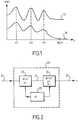
- the curve 11 in FIG. 1is a frequency spectral representation of a speech signal representing the amplitude P of the signal spectrum as a function of its frequency f.
- This signalcan be analog or digital. In the latter case, it can for example come from the output of a method-based predictive speech decoder LPC analysis commonly used in mobile radiotelephony and in particular in GSM type systems.
- This spectrumpresents formants or peaks of amplitudes at frequencies f1, f2 and f3 separated by valleys, f1, f2 and f3 being less than the highest frequency of the spectrum denoted Fe / 2.
- a post-filtering deviceintended to amplify the formants and dig the valleys in order to increase the contrast of the signal.
- the result after filteringis represented by curve 13.
- the effect of post-filteringis the increase in speech intelligibility. It is a subjective indicator depending on ear sensitivity.
- a post-filtercan be used to process speech signals, in particular to improve intelligibility and partially compensate for losses and errors due to coding, decoding and transmission. It has many applications, in speech decoders and noise cancellation devices.
- Figure 2shows schematically a post-filtering device 20 according to the invention receiving as input a speech signal 21 having a spectrum of the type of that bearing the reference 11 in FIG. 1 and outputting a filtered signal 22, the spectrum of which can be represented by curve 13. It includes a short-term predictive analysis circuit 23 of the LPC type to determine the LPC parameters of the speech signal and an extraction circuit 25 cooperating with a calculating member 26 to sample at the output of the predictive analysis circuit 23 of the pole values and to supply them as input to the calculation unit 26 to synthesize a digital post-filter of the zero-pole type, intended to filter the speech signal 21 for get signal 22.
- a short-term predictive analysis circuit 23 of the LPC typeto determine the LPC parameters of the speech signal
- an extraction circuit 25cooperating with a calculating member 26 to sample at the output of the predictive analysis circuit 23 of the pole values and to supply them as input to the calculation unit 26 to synthesize a digital post-filter of the zero-pole type, intended to filter the speech signal 21 for get signal 22.
- the input signal 21is sampled at a frequency Fe, approximately twice equal to the highest frequency of the original speech signal, so that the predictive analysis circuit 23 determines, every 160 samples for example, the LPC parameters of the speech signal.
- the residual error of the signalis obtained at the output of the filter A (z) which will then be filtered by a synthesis filter, inverse to the analysis filter, to reproduce the speech signal before the post- filtering.
- the poles of the post-filter intended to produce the signal 22are supplied to the calculation unit 26 by the extraction circuit 25 which obtains them by extraction of the roots p i of the polynomial A (z).
- the calculating member 26first classifies the roots pi in order of increasing frequencies between about 0 and 4 kHz, the sampling frequency Fe being close to 8 kHz.
- ⁇ d and ⁇ nare weighting coefficients indicating the distance from the root to the unit circle as illustrated in Figure 5, with ⁇ n ⁇ d ⁇ 1.
- K0is a step of receiving an analog or digital speech signal, having a frequency spectrum having formants separated by valleys.
- the second step, K1performs a short-term predictive analysis of the received signal to determine coefficients a i of the LPC analysis filter characteristic of the signal to be processed.
- Step K2consists in extracting the roots p i from the LPC filter.
- Step K3performs an interpolation between the roots p i in order to deduce therefrom values r i .
- Step K4is a step of synthesizing a digital filter W (z) of the zero-pole type, whose poles are the roots p i of the LPC filter and whose zeros are the values r i .
- step K5consists in applying the synthesized filter to the speech signal to provide at output a signal whose spectrum is modified compared to the spectrum of the input signal in the direction of an amplification of the formants and an accentuation of the valleys .
- certain steps the purpose of which is to provide calculation or analysis results used in other stepscan be performed prior to the signal reception step K0.
- a system GSM typethe communications chain of which is illustrated in FIG. 4.
- LPC analysisis performed during the transmission of the message during the speech signal coding.
- LPC parameters, used to produce the speech model which will then be transmitted on the transmission channel,are thus available as soon as the message, while the post-filtering process is executed at the end of the reception chain.
- the step of predictive analysis of the speech signal K1can therefore advantageously be carried out independently of the post-filtering process, before the step of receiving the signal K0 according to said process and the results will be taken from the speech coder to synthesize the speech and the post-filter.
- this predictive analysis stepcan be performed upon reception of the signal, possibly by the decoder itself or even on the signal already decoded.
- Figure 4is a block diagram of a digital communications system in classic baseband. It includes a broadcast channel 31, at least one channel transmission 32 and a reception chain 33.
- the original speech signal 5the spectrum of which frequency is represented by the curve 11 in figure 1 is received at the input of the chain emission 31 while the filtered speech signal S 'whose spectrum is represented by the curve 13 is provided at the output of the reception chain 33.
- the systemincludes transmission a preprocessing block 34, a speech coding block 35, a coding block channel 36 and on reception a channel decoding block 37, a decoding block of speech 38 and a post-processing block 39.
- the preprocessing block 34prepares the speech signal for encoding.
- Speech coding 35consists of modeling the speech and reducing the amount of information to be transmitted. For this, we use a method including a short-term prediction as described in the recommendation ETS 300 961 dated December 97 second edition, paragraph 3.1, to produce a speech model characterized by LPC filter parameters. These parameters are transmitted to the decoding block 38 to reconstruct the speech message.
- the purpose of the post-processing block 39is to improve the audio quality of the signal supplied at the output and in particular its intelligibility.
- the zerosare calculated to be placed about halfway between the poles to considerably accentuate the phenomenon sought.
- This arrangement of the poles and zerosamplifies the accentuation of the formants by increasing the amplitude of the maxima and decreasing that of the minima.
- the relative position of zeros and polesis represented in the unit circle at the figure 5.
- the crossesindicate the pole values and the circles the zero values of the post-filter W (z).
- the angle of the point considered in relation to the abscissaindicates its frequency.
- the distance of the point from the center of the circleindicates its amplitude.
- the values of zeros and poles of a post-filter classicWe note that in the case of the classic post-filter, the poles and zeros are located at same frequencies, which are also the frequencies of the formants. However, in the post-filter according to the invention, the zeros are located on an intermediate frequency between 2 poles.
- Classic post-filtersproduce a signal whose sound aspect is all the more more synthetic than they improve intelligibility. According to an advantage of the invention, this post-filtering produces an output signal whose synthetic tone is weaker than for conventional post-filters, while significantly increasing the intelligibility of the signal of speech. The result is a real improvement in the audio quality of the speech signal in exit from the communications chain.
- the telephone receiver shown schematically in Figure 6includes a chain transmission consisting of a microphone 61, an analog / digital A / D converter, a speech coder 62, a channel coder 63 and a module dedicated to the radio part frequency 64 connected to a duplexer 65 coupled to a transmit / receive antenna 66.
- the reception chaincomprises in addition to the antenna 66, the duplexer 65 and the radio module 64, a channel decoder 67, speech decoder 68, digital to analog converter D / A and a loudspeaker 69.
- the blocks 62, 63, 67 and 68can be produced by a signal processor of the DSP type (from the English Digital Signal Processor).
- the LPC analysis partis performed in the DSP at the speech coder 62 and the post-filtering part is part speech decoder 68.
Landscapes
- Engineering & Computer Science (AREA)
- Signal Processing (AREA)
- Physics & Mathematics (AREA)
- Health & Medical Sciences (AREA)
- Audiology, Speech & Language Pathology (AREA)
- Human Computer Interaction (AREA)
- Computational Linguistics (AREA)
- Acoustics & Sound (AREA)
- Multimedia (AREA)
- Computer Networks & Wireless Communication (AREA)
- Compression, Expansion, Code Conversion, And Decoders (AREA)
- Transmission Systems Not Characterized By The Medium Used For Transmission (AREA)
- Telephone Function (AREA)
Abstract
Description
Translated fromFrenchL'invention concerne un dispositif de filtrage numérique pour filtrer un signal deparole ayant un spectre de fréquence présentant des formants séparés par des vallées, ledispositif comportant un circuit d'analyse prédictive du signal de parole et un organe decalcul pour synthétiser un post-filtre numérique du type zéros-pôles destiné à amplifier lesformants et creuser les vallées.The invention relates to a digital filtering device for filtering a signalspeech having a frequency spectrum having formants separated by valleys, thedevice comprising a circuit for predictive analysis of the speech signal and a device forcalculation to synthesize a digital post-filter of the zero-pole type intended to amplify theformants and dig the valleys.
Elle concerne également un récepteur téléphonique destiné à recevoir un signal deparole ayant un spectre de fréquence présentant des formants séparés par des vallées,comprenant un circuit d'analyse prédictive du signal de parole et un organe de calcul poursynthétiser un post-filtre numérique du type zéros-pôles destiné à amplifier les formants etcreuser les vallées.It also relates to a telephone receiver intended to receive a signal ofspeech having a frequency spectrum having formants separated by valleys,comprising a circuit for predictive analysis of the speech signal and a calculation unit forsynthesize a digital post-filter of the zero-pole type intended to amplify the formants anddig the valleys.
Elle concerne un système de communication de signaux de parole en bande debase ayant au moins un canal de transmission et comportant:
- un dispositif de codage / décodage de parole prédictif pour restituer un signal deparole numérique à partir d'un signal original codé transmis sur ledit canal,
- un bloc de filtrage pour filtrer ledit signal de parole numérique.
- a predictive speech coding / decoding device for reproducing a digital speech signal from an original coded signal transmitted on said channel,
- a filter block for filtering said digital speech signal.
Elle concerne encore un procédé de filtrage pour filtrer un signal de parole ayantun spectre de fréquence présentant des formants séparés par des vallées, en vue d'amplifierles formants et creuser les vallées, comprenant:
- une étape d'analyse prédictive du signal de parole pour déterminer des coefficientsLPC,
- une étape de calcul pour synthétiser un filtre du type zéros-pôles à partir desditscoefficients LPC et
- une étape de filtrage pour appliquer ledit filtre synthétisé au signal de parole.
- a step of predictive analysis of the speech signal to determine LPC coefficients,
- a computation step for synthesizing a zero-pole type filter from said LPC coefficients and
- a filtering step for applying said synthesized filter to the speech signal.
L'invention concerne enfin un signal de parole obtenu par application d'un filtrenumérique du type zéros-pôles à un premier signal de parole ayant un spectre de fréquenceprésentant des formants séparés par des vallées, ledit premier signal pouvant être modéliséà l'aide d'un filtre LPC inverse du type tous-pôles.The invention finally relates to a speech signal obtained by applying a filter.digital of the zero-pole type with a first speech signal having a frequency spectrumhaving formants separated by valleys, said first signal being able to be modeledusing an inverse LPC filter of the all-pole type.
Elle a de nombreuses applications dans les communications vocales, notammentdans les systèmes de radiotéléphonie mobile.It has many applications in voice communications, includingin mobile radio systems.
Le brevet américain publié sous le numéro 4 617 676 décrit un système decommunications numériques recevant en entrée un signal de parole ayant un spectre defréquence présentant des formants séparés par des vallées, le système comprenant un décodeur prédictif de parole pour déterminer des paramètres prédictifs du signal reçu et unbloc de post-filtrage destiné à fournir en sortie un signal modifié en fonction des paramètresprédictifs, pour amplifier les formants et creuser les vallées.The American patent published under the
L'intérêt du post-filtrage est d'augmenter la qualité audio de signaux de parole envue d'améliorer leur intelligibilité et ainsi mieux répondre aux besoins des utilisateurs. Dansla suite, on désigne par le terme post-filtre, un filtre destiné à améliorer la qualité audio dusignal.The advantage of post-filtering is to increase the audio quality of speech signals byto improve their intelligibility and thus better meet the needs of users. Inhereinafter, the term post-filter is used to designate a filter intended to improve the audio quality of thesignal.
L'art antérieur cité s'applique à un système de communications numériquescomportant, en émission, un codeur prédictif de parole pour générer un modèle de parole àpartir de paramètres LPC (de l'anglais Linear Predictive Coding) obtenus à l'aide d'un filtred'analyse LPC du type zéros-pôles, c'est-à-dire ayant des pôles et des zéros, et en réception,un décodeur prédictif pour restituer un signal de parole à partir du modèle reçu, à l'aide d'unfiltre de synthèse LPC et des moyens de post-filtrage pour améliorer la qualité du signalreconstitué en fonction des paramètres LPC fournis par le codeur prédictif. Pour le post-filtrage,il faut synthétiser un filtre numérique, dit post-filtre, de type zéros-pôlesdont lesvaleurs de zéros et de pôles correspondent, à un facteur près, aux valeurs de zéros et depôles du filtre d'analyse LPC. Le brevet américain cité prévoit ainsi d'utiliser, pour constituerle post-filtre, les pôles et les zéros obtenus par l'analyse LPC effectuée par le codeur deparole et transmis au décodeur. Les valeurs de pôles et de zéros reçues par le décodeur sontalors situées aux mêmes fréquences respectivement que les formants et les vallées du signald'entrée.The cited prior art applies to a digital communications systemcomprising, in transmission, a predictive speech coder for generating a speech model withfrom LPC (Linear Predictive Coding) parameters obtained using a filterLPC analysis of the zero-pole type, that is to say having poles and zeros, and in reception,a predictive decoder for reproducing a speech signal from the received model, using aLPC synthesis filter and post-filtering means to improve the signal qualityreconstructed according to the LPC parameters provided by the predictive coder. For post-filtering,you have to synthesize a digital filter, called post-filter, of the zero-pole typewhosevalues of zeros and poles correspond, to within a factor, to the values of zeros andpoles of the LPC analysis filter. The cited US patent thus provides for using, to constitutethe post-filter, the poles and the zeros obtained by the LPC analysis carried out by thespeech and transmitted to the decoder. The pole and zero values received by the decoder arethen located at the same frequencies respectively as the formants and the valleys of the signalentry.
La présente invention prévoit au contraire de n'utiliser que des valeurs de pôlesdéfinis par une analyse LPC et de calculer les valeurs de zéros du post-filtrepar interpolationentre les valeurs de pôles issues de l'analyse LPC. Il en résulte une plus grande flexibilitédans la détermination des zéros dont la position peut être fixée avec précision en fonction dela qualité et de l'intelligibilité recherchées pour le signal de sortie. De plus, l'invention estcompatible avec les codeurs de parole les plus répandus en radiotéléphonie GSM (del'anglais Global System for Mobile communications), notamment les codeurs de parole pleindébit conformes à la recommandation ETS 300 961 paragraphe 3, datée de décembre 97,deuxième édition. Ces codeurs fonctionnent avec des filtres d'analyse LPC de type tous-pôlesqui ne transmettent au décodeur que des valeurs de pôle.The present invention, on the contrary, provides for using only pole values.defined by an LPC analysis and calculate the post-filter zero valuesby interpolationbetween the pole values from the LPC analysis. This results in greater flexibilityin the determination of zeros whose position can be fixed precisely as a function ofthe quality and intelligibility sought for the output signal. In addition, the invention iscompatible with the most common speech coders in GSM radiotelephony (fromEnglish Global System for Mobile communications), including full speech codersdebit in accordance with recommendation ETS 300 961 paragraph 3, dated December 97,second edition. These encoders work with all-pole type LPC analysis filterswhich only transmit pole values to the decoder.
Selon l'invention, il est prévu un dispositif de filtrage et un récepteur téléphoniquetels que mentionnés dans le paragraphe introductif remarquables en ce qu'ils comportent uncircuit d'extraction pour prélever des valeurs de pôles en sortie du circuit d'analyse prédictive et pour les fournir audit organe de calcul et des moyens d'interpolation entre lesdites valeursde pôles pour déterminer les valeurs de zéros.According to the invention, there is provided a filtering device and a telephone receiveras mentioned in the introductory paragraph remarkable in that they include aextraction circuit for taking pole values at the output of the predictive analysis circuitand to supply them to said calculation unit and means of interpolation between said valuesof poles to determine the zero values.
L'invention prévoit également un système de communications tel que mentionnédans le paragraphe introductif, remarquable en ce que le bloc de filtrage comporte desmoyens de calcul pour synthétiser un filtre numérique du type zéros-pôles,un circuitd'extraction pour prélever des valeurs de pôles en sortie du dispositif de codage / décodagede parole prédictif et des moyens d'interpolation entre lesdites valeurs de pôles pourdéterminer les valeurs de zéros.The invention also provides a communications system as mentionedin the introductory paragraph, remarkable in that the filter block includescalculation means for synthesizing a digital filter of the zero-pole type,a circuitof extraction to take pole values at the output of the coding / decoding devicepredictive speech and interpolation means between said pole values fordetermine the zero values.
Il est aussi prévu un procédé du genre mentionné dans le paragraphe introductifremarquable en ce que l'étape de calcul comprend:
- une étape d'extraction destinée à extraire les racines d'un polynôme LPC construit àpartir desdits coefficients LPC pour en déduire les valeurs de pôles et
- une étape d'interpolation entre lesdites valeurs de pôles pour déterminer lesditesvaleurs de zéros.
- an extraction step intended to extract the roots of an LPC polynomial constructed from said LPC coefficients in order to deduce therefrom the pole values and
- an interpolation step between said pole values to determine said zero values.
Enfin, l'invention s'applique à un signal tel que décrit au paragraphe introductifcaractérisé en ce que les valeurs de pôles du filtre de type zéros-pôlessont obtenues parextraction des pôles dudit filtre LPC inverse et en ce que les valeurs de zéros sont obtenuespar un calcul d'interpolation entre lesdites valeurs de pôles du filtre de type tous-pôles.Finally, the invention applies to a signal as described in the introductory paragraphcharacterized in that the pole values of the zero-pole type filterare obtained byextraction of the poles from said inverse LPC filter and in that the zero values are obtainedby an interpolation calculation between said pole values of the all-pole type filter.
L'invention est particulièrement avantageuse lorsque le signal a préalablement subiune analyse prédictive LPC et que ses paramètres LPC sont disponibles au moment du post-filtrage.The invention is particularly advantageous when the signal has previously undergonepredictive LPC analysis and that its LPC parameters are available at the time of post-filtering.
La description suivante, faite en regard des dessins ci-annexés, le tout donné àtitre d'exemple non limitatif fera bien comprendre comment l'invention peut être réalisée.
La courbe 11 sur la figure 1 est une représentation spectrale fréquentielle d'unsignal de parole représentant l'amplitude P du spectre du signal en fonction de sa fréquencef. Ce signal peut être analogique ou numérique. Dans ce dernier cas, il peut par exempleprovenir de la sortie d'un décodeur de parole prédictif du type basé sur des méthodesd'analyse LPC couramment utilisées en radiotéléphonie mobile et en particulier dans lessystèmes de type GSM.The
Ce spectre présente des formants ou pics d'amplitudes aux fréquences f1, f2 et f3séparés par des vallées, f1, f2 et f3 étant inférieures à la plus haute fréquence du spectrenotée Fe/2. Pour améliorer la qualité audio d'un tel signal, on prévoit un dispositif de post-filtragedestiné à amplifier les formants et creuser les vallées afin d'augmenter le contrastedu signal. Le résultat après filtrage est représenté par la courbe 13. L'effet du post-filtrageest l'augmentation de l'intelligibilité de la parole. C'est un indicateur subjectif dépendant dela sensibilité de l'oreille. Un post-filtre peut être utilisé pour traiter des signaux de parole,notamment pour améliorer l'intelligibilité et compenser partiellement les pertes et les erreursdues au codage, au décodage et à la transmission. Il a de nombreuses applications, dans lesdécodeurs de parole et les dispositifs de suppression de bruit.This spectrum presents formants or peaks of amplitudes at frequencies f1, f2 and f3separated by valleys, f1, f2 and f3 being less than the highest frequency of the spectrumdenoted Fe / 2. To improve the audio quality of such a signal, a post-filtering device is provided.intended to amplify the formants and dig the valleys in order to increase the contrastof the signal. The result after filtering is represented by
La figure 2 schématise un dispositif de post-filtrage 20 selon l'invention recevanten entrée un signal de parole 21 ayant un spectre du type de celui portant la référence 11sur la figure 1 et fournissant en sortie un signal filtré 22 dont le spectre peut être représentépar la courbe 13. Il comporte un circuit d'analyse prédictive à court terme 23 de type LPCpour déterminer les paramètres LPC du signal de parole et un circuit d'extraction 25coopérant avec un organe de calcul 26 pour prélever en sortie du circuit d'analyse prédictive23 des valeurs de pôles et pour les fournir en entrée à l'organe de calcul 26 pour synthétiserun post-filtre numérique de type zéros-pôles, destiné à filtrer le signal de parole 21 pourobtenir le signal 22.Figure 2 shows schematically a
Selon cet exemple, le signal d'entrée 21 est échantillonné à une fréquence Fe,environ deux fois égale à la plus haute fréquence du signal de parole original, de façon à ceque le circuit d'analyse prédictive 23 détermine, tous les 160 échantillons par exemple, lesparamètres LPC du signal de parole. Ces paramètres, notés ai, sont obtenus à l'aide d'unfiltre d'analyse LPC A(z) dont l'équation s'écrit par exemple:
Les pôles du post-filtre destiné à produire le signal 22 sont fournis à l'organe decalcul 26 par le circuit d'extraction 25 qui les obtient par extraction des racines pi dupolynôme A(z). Pour calculer les zéros, l'organe de calcul 26 effectue d'abord un classementdes racines pi par ordre de fréquences croissantes entre 0 et 4 KHz environ, la fréquenced'échantillonnage Fe étant voisine de 8 KHz. On obtient ensuite les valeurs de 〈〈 zéros 〉〉,notées ri, par un calcul d'interpolation entre les racines pi du polynôme A(z):
Un exemple de procédé de filtrage selon l'invention va maintenant être décrit endétails à l'aide de la figure 3. Il comprend les étapes K0 à K5 dont l'ordre d'exécution peutsubir certaines variantes. La première, K0, est une étape de réception d'un signal de paroleanalogique ou numérique, ayant un spectre de fréquence présentant des formants séparéspar des vallées. La deuxième étape, K1, réalise une analyse prédictive à court terme dusignal reçu pour déterminer des coefficients ai du filtre d'analyse LPC caractéristique dusignal à traiter. L'étape K2 consiste à extraire les racines pi du filtre LPC. L'étape K3 effectueune interpolation entre les racines pi pour en déduire des valeurs ri. L'étape K4 est une étapede synthèse d'un filtre numérique W(z) du type zéros-pôles, dont les pôles sont les racines pidu filtre LPC et dont les zéros sont les valeurs ri. Enfin, l'étape K5 consiste à appliquer lefiltre synthétisé au signal de parole pour fournir en sortie un signal dont le spectre estmodifié par rapport au spectre du signal d'entrée dans le sens d'une amplification desformants et un accentuation des vallées.An example of a filtering method according to the invention will now be described in detail with the aid of FIG. 3. It comprises steps K0 to K5, the order of execution of which may undergo certain variants. The first, K0, is a step of receiving an analog or digital speech signal, having a frequency spectrum having formants separated by valleys. The second step, K1, performs a short-term predictive analysis of the received signal to determine coefficients ai of the LPC analysis filter characteristic of the signal to be processed. Step K2 consists in extracting the roots pi from the LPC filter. Step K3 performs an interpolation between the roots pi in order to deduce therefrom values ri . Step K4 is a step of synthesizing a digital filter W (z) of the zero-pole type, whose poles are the roots pi of the LPC filter and whose zeros are the values ri . Finally, step K5 consists in applying the synthesized filter to the speech signal to provide at output a signal whose spectrum is modified compared to the spectrum of the input signal in the direction of an amplification of the formants and an accentuation of the valleys .
Selon des variantes de réalisation de ce procédé, certaines étapes dont le but estde fournir des résultats de calcul ou d'analyse utilisés dans d'autres étapes peuvent êtreréalisées préalablement à l'étape K0 de réception du signal. Prenons l'exemple d'un systèmede type GSM dont la chaíne de communications est illustrée à la figure 4. Selon la normeGSM, une analyse LPC est effectuée au cours de l'émission du message pendant la phase de codage du signal de parole. Les paramètres LPC, utilisés pour produire le modèle de parolequi sera ensuite transmis sur le canal de transmission, sont ainsi disponible dès l'émission dumessage, alors que le procédé de post-filtrage est exécuté à la fin de la chaíne de réception.According to alternative embodiments of this method, certain steps the purpose of which isto provide calculation or analysis results used in other steps can beperformed prior to the signal reception step K0. Take the example of a systemGSM type, the communications chain of which is illustrated in FIG. 4. According to the standardGSM, an LPC analysis is performed during the transmission of the message during thespeech signal coding. LPC parameters, used to produce the speech modelwhich will then be transmitted on the transmission channel, are thus available as soon as themessage, while the post-filtering process is executed at the end of the reception chain.
Dans une application de type GSM par exemple, l'étape d'analyse prédictive dusignal de parole K1 pourra donc être avantageusement effectuée indépendamment duprocédé de post-filtrage, avant l'étape de réception du signal K0 selon ledit procédé et lesrésultats seront prélevés au niveau du codeur de parole pour synthétiser la parole et le post-filtre.On peut également préférer refaire une analyse LPC spécialement pour le post-filtrecomme dans le cas général. Dans un système de communications qui ne prévoit pasd'analyse LPC, cette étape d'analyse prédictive pourra être réalisée à la réception du signal,éventuellement par le décodeur lui-même ou encore sur le signal déjà décodé.In a GSM type application for example, the step of predictive analysis of thespeech signal K1 can therefore advantageously be carried out independently of thepost-filtering process, before the step of receiving the signal K0 according to said process and theresults will be taken from the speech coder to synthesize the speech and the post-filter.We can also prefer to redo an LPC analysis especially for the post-filteras in the general case. In a communications system that doesn't planLPC analysis, this predictive analysis step can be performed upon reception of the signal,possibly by the decoder itself or even on the signal already decoded.
La figure 4 est un schéma bloc d'un système de communications numériques enbande de base classique. Il comprend une chaíne d'émission 31, au moins un canal detransmission 32 et une chaíne de réception 33. Selon un mode de réalisation de l'inventionconvenant particulièrement au système GSM, le signal de parole original 5 dont le spectre defréquence est représenté par la courbe 11 sur la figure 1 est reçu en entrée de la chaíned'émission 31 tandis que le signal de parole filtré S' dont le spectre est représenté par lacourbe 13 est fourni en sortie de la chaíne de réception 33. Le système comprend enémission un bloc de pré-traitement 34, un bloc de codage de parole 35, un bloc de codagede canal 36 et en réception un bloc de décodage de canal 37, un bloc de décodage deparole 38 et un bloc de post-traitement 39.Figure 4 is a block diagram of a digital communications system inclassic baseband. It includes a
Le bloc de pré-traitement 34 prépare le signal de parole pour 'encodage. Lecodage de parole 35 consiste à modéliser la parole et à réduire la quantité d'informations àtransmettre. Pour cela, on utilise une méthode incluant une prédiction à court terme telleque décrite dans la recommandation ETS 300 961 datée de décembre 97 seconde édition,paragraphe 3.1, pour produire un modèle de parole caractérisé par des paramètres de filtreLPC. Ces paramètres sont transmis au bloc de décodage 38 pour reconstituer le message deparole. Le filtre d'analyse A(z) utilisé pour extraire les caractéristiques LPC du signal deparole peut par exemple s'écrire:
Le bloc de codage de canal 36 prépare les données pour la transmission et le blocde décodage de canal 37 décode les données transmises pour permettre au décodeur deparole 38 de reconstituer le message de parole selon le processus inverse du codage. Il reçoit donc le modèle de parole transmis sur le canal et lui applique le filtre de synthèse noté1/A(z) inverse du filtre d'analyse:
Le bloc de post-traitement 39 a pour objet d'améliorer la qualité audio du signalfourni en sortie et en particulier son intelligibilité. Un post-filtre classique s'écrit sous laforme:
Dans le post-filtre selon l'invention, les zéros sont calculés pour être placés environà mi-distance des pôles pour accentuer considérablement le phénomène recherché. Cettedisposition des pôles et des zéros amplifie l'accentuation des formants en augmentantl'amplitude des maxima et en diminuant celle des minima. Les valeurs de zéros sontobtenues artificiellement par un calcul d'interpolation entre les valeurs de pôles extraites del'analyse LPC:
La position relative des zéros et des pôles est représentée dans le cercle unité à lafigure 5. Les croix indiquent les valeurs de pôles et les ronds les valeurs de zéros du post-filtreW(z). L'angle du point considéré par rapport à l'abcisse indique sa fréquence. Ladistance du point par rapport au centre du cercle indique son amplitude. On a aussi indiquésur la figure en pointillés, les valeurs de zéros et de pôles d'un post-filtreclassique. Onremarque que dans le cas du post-filtre classique, les pôles et les zéros sont situés aux mêmes fréquences, qui sont également les fréquences des formants. En revanche, dans lepost-filtre selon l'invention, les zéros sont situés sur une fréquence intermédiaire entre 2pôles.The relative position of zeros and poles is represented in the unit circle at thefigure 5. The crosses indicate the pole values and the circles the zero values of the post-filterW (z). The angle of the point considered in relation to the abscissa indicates its frequency. Thedistance of the point from the center of the circle indicates its amplitude. We also indicatedin the dotted figure, the values of zeros and poles of a post-filterclassic. Wenote that in the case of the classic post-filter, the poles and zeros are located atsame frequencies, which are also the frequencies of the formants. However, in thepost-filter according to the invention, the zeros are located on an intermediate frequency between 2poles.
Les post-filtres classiques produisent un signal dont l'aspect sonore est d'autantplus synthétique qu'ils en améliore l'intelligibilité. Selon un avantage de l'invention, ce post-filtrageproduit un signal de sortie dont la sonorité synthétique est plus faiblement marquéeque pour les post-filtres classiques, tout en augmentant notablement l'intelligibilité du signalde parole. Le résultat est une réelle amélioration de la qualité audio du signal de parole ensortie de la chaíne de communications.Classic post-filters produce a signal whose sound aspect is all the moremore synthetic than they improve intelligibility. According to an advantage of the invention, this post-filteringproduces an output signal whose synthetic tone is weakerthan for conventional post-filters, while significantly increasing the intelligibility of the signalof speech. The result is a real improvement in the audio quality of the speech signal inexit from the communications chain.
Le récepteur téléphonique schématisé à la figure 6 comprend une chaíned'émission constituée d'un microphone 61, d'un convertisseur analogique / numérique A/D,d'un codeur de parole 62, d'un codeur de canal 63 et d'un module dédié à la partie radiofréquence 64 relié à un duplexeur 65 couplé à une antenne d'émission / réception 66. Lachaíne de réception comprend outre l'antenne 66, le duplexeur 65 et le module radio 64, undécodeur de canal 67, un décodeur de parole 68, un convertisseur numérique / analogiqueD/A et un haut-parleur 69. Les blocs 62, 63, 67 et 68 peuvent être réalisés par unprocesseur de signal du type DSP (de l'anglais Digital Signal Processor).The telephone receiver shown schematically in Figure 6 includes a chaintransmission consisting of a
Selon un mode de réalisation préféré de l'invention, la partie analyse LPC esteffectuée dans le DSP au niveau du codeur de parole 62 et la partie post-filtragefait partiedu décodeur de parole 68.According to a preferred embodiment of the invention, the LPC analysis part isperformed in the DSP at the
On a ainsi décrit et illustré à l'aide d'exemples un signal de parole, un dispositif etun procédé de filtrage, un récepteur téléphonique et un système de communications pouraméliorer l'intelligibilité du signal de parole. Bien entendu, des variantes de réalisationpourront être apportées sans sortir du cadre de l'invention, notamment en ce qui concernela structure des filtres utilisés pour l'analyse et la synthèse prédictive à court terme de laparole.We have thus described and illustrated with examples a speech signal, a device anda filtering method, a telephone receiver and a communications system forimprove the intelligibility of the speech signal. Of course, variant embodimentsmay be made without departing from the scope of the invention, in particular as regardsthe structure of the filters used for short-term predictive analysis and synthesis of thespeech.
Claims (8)
Translated fromFrenchApplications Claiming Priority (2)
| Application Number | Priority Date | Filing Date | Title |
|---|---|---|---|
| FR9811812 | 1998-09-22 | ||
| FR9811812AFR2783651A1 (en) | 1998-09-22 | 1998-09-22 | DEVICE AND METHOD FOR FILTERING A SPEECH SIGNAL, RECEIVER AND TELEPHONE COMMUNICATIONS SYSTEM |
Publications (1)
| Publication Number | Publication Date |
|---|---|
| EP0989544A1true EP0989544A1 (en) | 2000-03-29 |
Family
ID=9530706
Family Applications (1)
| Application Number | Title | Priority Date | Filing Date |
|---|---|---|---|
| EP99203004AWithdrawnEP0989544A1 (en) | 1998-09-22 | 1999-09-15 | Device and method for filtering a speech signal, receiver and telephone communications system |
Country Status (7)
| Country | Link |
|---|---|
| US (1) | US6167371A (en) |
| EP (1) | EP0989544A1 (en) |
| JP (1) | JP2000099095A (en) |
| KR (1) | KR20000028699A (en) |
| CN (1) | CN1135003C (en) |
| FR (1) | FR2783651A1 (en) |
| TW (1) | TW444440B (en) |
Families Citing this family (7)
| Publication number | Priority date | Publication date | Assignee | Title |
|---|---|---|---|---|
| US6850884B2 (en)* | 2000-09-15 | 2005-02-01 | Mindspeed Technologies, Inc. | Selection of coding parameters based on spectral content of a speech signal |
| US6842733B1 (en)* | 2000-09-15 | 2005-01-11 | Mindspeed Technologies, Inc. | Signal processing system for filtering spectral content of a signal for speech coding |
| KR100969788B1 (en) | 2003-08-26 | 2010-07-13 | 엘지전자 주식회사 | Device and method for automatically adjusting audio output of mobile communication terminal |
| CN105551497B (en)* | 2013-01-15 | 2019-03-19 | 华为技术有限公司 | Coding method, coding/decoding method, encoding apparatus and decoding apparatus |
| KR101475894B1 (en)* | 2013-06-21 | 2014-12-23 | 서울대학교산학협력단 | Method and apparatus for improving disordered voice |
| JP6700507B6 (en)* | 2014-06-10 | 2020-07-22 | エムキューエー リミテッド | Digital encapsulation of audio signals |
| US9912414B2 (en)* | 2014-11-14 | 2018-03-06 | Zte Corporation | Iterative post-equalization for coherent optical receivers |
Citations (3)
| Publication number | Priority date | Publication date | Assignee | Title |
|---|---|---|---|---|
| EP0573398A2 (en)* | 1992-06-01 | 1993-12-08 | Hughes Aircraft Company | C.E.L.P. Vocoder |
| EP0763818A2 (en)* | 1995-09-14 | 1997-03-19 | Kabushiki Kaisha Toshiba | Formant emphasis method and formant emphasis filter device |
| EP0774750A2 (en)* | 1995-11-15 | 1997-05-21 | Nokia Mobile Phones Ltd. | Determination of line spectrum frequencies for use in a radiotelephone |
Family Cites Families (4)
| Publication number | Priority date | Publication date | Assignee | Title |
|---|---|---|---|---|
| US4617676A (en)* | 1984-09-04 | 1986-10-14 | At&T Bell Laboratories | Predictive communication system filtering arrangement |
| US4969192A (en)* | 1987-04-06 | 1990-11-06 | Voicecraft, Inc. | Vector adaptive predictive coder for speech and audio |
| US4868867A (en)* | 1987-04-06 | 1989-09-19 | Voicecraft Inc. | Vector excitation speech or audio coder for transmission or storage |
| US5864798A (en)* | 1995-09-18 | 1999-01-26 | Kabushiki Kaisha Toshiba | Method and apparatus for adjusting a spectrum shape of a speech signal |
- 1998
- 1998-09-22FRFR9811812Apatent/FR2783651A1/ennot_activeWithdrawn
- 1999
- 1999-06-02TWTW088109133Apatent/TW444440B/enactive
- 1999-09-13USUS09/395,050patent/US6167371A/ennot_activeExpired - Fee Related
- 1999-09-15EPEP99203004Apatent/EP0989544A1/ennot_activeWithdrawn
- 1999-09-20KRKR1019990040397Apatent/KR20000028699A/ennot_activeWithdrawn
- 1999-09-20CNCNB991203275Apatent/CN1135003C/ennot_activeExpired - Fee Related
- 1999-09-21JPJP11266851Apatent/JP2000099095A/enactivePending
Patent Citations (3)
| Publication number | Priority date | Publication date | Assignee | Title |
|---|---|---|---|---|
| EP0573398A2 (en)* | 1992-06-01 | 1993-12-08 | Hughes Aircraft Company | C.E.L.P. Vocoder |
| EP0763818A2 (en)* | 1995-09-14 | 1997-03-19 | Kabushiki Kaisha Toshiba | Formant emphasis method and formant emphasis filter device |
| EP0774750A2 (en)* | 1995-11-15 | 1997-05-21 | Nokia Mobile Phones Ltd. | Determination of line spectrum frequencies for use in a radiotelephone |
Also Published As
| Publication number | Publication date |
|---|---|
| KR20000028699A (en) | 2000-05-25 |
| TW444440B (en) | 2001-07-01 |
| JP2000099095A (en) | 2000-04-07 |
| US6167371A (en) | 2000-12-26 |
| CN1249639A (en) | 2000-04-05 |
| CN1135003C (en) | 2004-01-14 |
| FR2783651A1 (en) | 2000-03-24 |
Similar Documents
| Publication | Publication Date | Title |
|---|---|---|
| EP2002428B1 (en) | Method for trained discrimination and attenuation of echoes of a digital signal in a decoder and corresponding device | |
| EP0782128B1 (en) | Method of analysing by linear prediction an audio frequency signal, and its application to a method of coding and decoding an audio frequency signal | |
| CA2436318C (en) | Noise reduction method and device | |
| EP1262956B1 (en) | Signal encoding method and apparatus | |
| KR101378696B1 (en) | Determining an upperband signal from a narrowband signal | |
| EP2104936B1 (en) | Low-delay transform coding using weighting windows | |
| FR2596936A1 (en) | VOICE SIGNAL TRANSMISSION SYSTEM | |
| FR3045915A1 (en) | ADAPTIVE CHANNEL REDUCTION PROCESSING FOR ENCODING A MULTICANAL AUDIO SIGNAL | |
| EP0998166A1 (en) | Device for audio processing,receiver and method for filtering the wanted signal and reproducing it in presence of ambient noise | |
| EP2936488B1 (en) | Effective attenuation of pre-echos in a digital audio signal | |
| FR3007563A1 (en) | ENHANCED FREQUENCY BAND EXTENSION IN AUDIO FREQUENCY SIGNAL DECODER | |
| EP0428445B1 (en) | Method and apparatus for coding of predictive filters in very low bitrate vocoders | |
| EP2347411B1 (en) | Pre-echo attenuation in a digital audio signal | |
| EP1275109B1 (en) | Spectral enhancing method and device | |
| EP0989544A1 (en) | Device and method for filtering a speech signal, receiver and telephone communications system | |
| EP1039736A1 (en) | Method and device for adaptive identification and related adaptive echo canceller | |
| EP0616315A1 (en) | Digital speech coding and decoding device, process for scanning a pseudo-logarithmic LTP codebook and process of LTP analysis | |
| EP0891617B1 (en) | Signal coding and decoding system, particularly for a digital audio signal | |
| EP1383109A1 (en) | Method and device for wide band speech coding | |
| FR2980620A1 (en) | Method for processing decoded audio frequency signal, e.g. coded voice signal including music, involves performing spectral attenuation of residue, and combining residue and attenuated signal from spectrum of tonal components | |
| FR2773653A1 (en) | Input sound digital word decoding/coding device, especially for analyzing and compressing inputs for recording | |
| WO2024213556A1 (en) | Optimized processing for reducing channels of a stereophonic audio signal | |
| FR3149160A1 (en) | Optimized channel reduction processing of a stereophonic audio signal | |
| EP1192618B1 (en) | Audio coding with adaptive liftering | |
| FR2821501A1 (en) | METHOD AND DEVICE FOR SPECTRAL RECONSTRUCTION OF AN INCOMPLETE SPECTRUM SIGNAL AND CODING / DECODING SYSTEM THEREOF |
Legal Events
| Date | Code | Title | Description |
|---|---|---|---|
| PUAI | Public reference made under article 153(3) epc to a published international application that has entered the european phase | Free format text:ORIGINAL CODE: 0009012 | |
| AK | Designated contracting states | Kind code of ref document:A1 Designated state(s):DE FR GB IT | |
| AX | Request for extension of the european patent | Free format text:AL;LT;LV;MK;RO;SI | |
| 17P | Request for examination filed | Effective date:20000929 | |
| AKX | Designation fees paid | Free format text:DE FR GB IT | |
| STAA | Information on the status of an ep patent application or granted ep patent | Free format text:STATUS: THE APPLICATION HAS BEEN WITHDRAWN | |
| 18W | Application withdrawn | Effective date:20040315 |