EP0989517B1 - Determining the position of eyes through detection of flashlight reflection and correcting defects in a captured frame - Google Patents
Determining the position of eyes through detection of flashlight reflection and correcting defects in a captured frameDownload PDFInfo
- Publication number
- EP0989517B1 EP0989517B1EP99202983AEP99202983AEP0989517B1EP 0989517 B1EP0989517 B1EP 0989517B1EP 99202983 AEP99202983 AEP 99202983AEP 99202983 AEP99202983 AEP 99202983AEP 0989517 B1EP0989517 B1EP 0989517B1
- Authority
- EP
- European Patent Office
- Prior art keywords
- color
- image
- frame
- captured
- illumination
- Prior art date
- Legal status (The legal status is an assumption and is not a legal conclusion. Google has not performed a legal analysis and makes no representation as to the accuracy of the status listed.)
- Expired - Lifetime
Links
Images


Classifications
- G—PHYSICS
- G06—COMPUTING OR CALCULATING; COUNTING
- G06V—IMAGE OR VIDEO RECOGNITION OR UNDERSTANDING
- G06V40/00—Recognition of biometric, human-related or animal-related patterns in image or video data
- G06V40/10—Human or animal bodies, e.g. vehicle occupants or pedestrians; Body parts, e.g. hands
- G06V40/18—Eye characteristics, e.g. of the iris
- G06V40/193—Preprocessing; Feature extraction
- G—PHYSICS
- G06—COMPUTING OR CALCULATING; COUNTING
- G06T—IMAGE DATA PROCESSING OR GENERATION, IN GENERAL
- G06T7/00—Image analysis
- G06T7/70—Determining position or orientation of objects or cameras
- G06T7/73—Determining position or orientation of objects or cameras using feature-based methods
- G06T7/74—Determining position or orientation of objects or cameras using feature-based methods involving reference images or patches
- G—PHYSICS
- G06—COMPUTING OR CALCULATING; COUNTING
- G06T—IMAGE DATA PROCESSING OR GENERATION, IN GENERAL
- G06T7/00—Image analysis
- G06T7/97—Determining parameters from multiple pictures
- G—PHYSICS
- G06—COMPUTING OR CALCULATING; COUNTING
- G06V—IMAGE OR VIDEO RECOGNITION OR UNDERSTANDING
- G06V40/00—Recognition of biometric, human-related or animal-related patterns in image or video data
- G06V40/10—Human or animal bodies, e.g. vehicle occupants or pedestrians; Body parts, e.g. hands
- G06V40/18—Eye characteristics, e.g. of the iris
- G06V40/19—Sensors therefor
- G—PHYSICS
- G06—COMPUTING OR CALCULATING; COUNTING
- G06T—IMAGE DATA PROCESSING OR GENERATION, IN GENERAL
- G06T2207/00—Indexing scheme for image analysis or image enhancement
- G06T2207/30—Subject of image; Context of image processing
- G06T2207/30216—Redeye defect
Definitions
- the inventionrelates generally to the field of digital image processing, and in particular detecting human eyes or even animal eyes in digital images. More specifically, the invention relates to a method and apparatus for fast and accurate eye detection by taking advantage of the red-eye effect, in case human beings are captured by the apparatus. Animal eyes may be detected by taking advantage of the eye-defect in images captured together with a flash light. In case of animal eyes the regions of an image showing the eye-defect are usually visible as bright green or yellow spots in the captured image frame.
- the inventionrelates to a method and apparatus for fast and automatic correction of eye-defects in captured image frames.
- the pupils of peoplesometimes appear red because the light is partially absorbed by capillaries in the retina.
- the light rays 70 from the flash illumination source 12enter the eye 2 through the eye lens 3, and form an image 12a of the illumination source 12 on retina 4.
- the eye-defect in captured imagesknown as the "red-eye effect" is mostly seen with human eyes. In case animals are captured, the eye-defect will show a bright green or yellow color. Animal eyes are generally more difficult to detect for pattern recognition algorithms due to the large variations in animal facial structure, complexion, hair and structure of the eyes itself.
- the light rays 80 reflected from the retina 4exit the eye 2 through the eye lens 3, and finally enter the camera lens 5. If the camera lens 5 is placed close to the illumination source 12, the red-eye effect will be maximized. In other words, the amount of red-eye or eye-defect being observed increases as the illumination source 12 gets closer to an optical axis 22 defined by the camera lens 5 (see also Fig. 3).
- the general technique for red-eye reduction in camerashas been to impact two parameters: (a) Reduce the pupil diameter of the subject, for example by emitting a series of small pre-flashes prior to capturing the desired image with full illumination; and, (b) Increase the flash to lens separation, so that the illumination impinging on the subject's eyes is reflected at an angle that misses the taking lens.
- U. S. Patent 5,570,434, issued October 29, 1996 to Badique, entitled “Circuit Arrangement for Recognizing A Human Face”,describes a circuit for recognizing a human face in a sequence of video images.
- the circuitincludes the steps of subtracting two consecutive image frames and using the areas of difference to determine if there is a moving object.
- the difference mapreceives further post-processing, culminating in a convolution to determine if a head and shoulders feature set is present in the scene.
- U. S. Patent 5,325,133, issued June 28, 1994 to Adachi, entitled “Device for Measuring a Retina Reflected Light Amount and a Gaze Detecting Apparatus Using the Same”describes a device for measuring reflected light from a retina and detecting the direction in which the user is looking with an apparatus.
- This apparatusdirects three sources of infrared emission, located at three different positions, toward a user's eyes.
- the systemlocates the pupils by pattern recognition or by red-eye ("detecting the frequency components corresponding to hemoglobin which is abundantly contained in the light reflected by the retina”). It then processes the retinal reflection based on the displacement angles to determine where the user's gaze is directed.
- the apparatus functionalityis keyed to computing the gaze angle from the three dimensional angular measurements, instead of locating eyes.
- This artdoes not mention the issue of spacing between emission source and image capture device. It teaches away from the current invention by its dependence on measuring angular separation between emission source and image pick-up source for a minimum of three emitter/detector pairs.
- U. S. Patent 5,231,674 issued July 27, 1993 to Cleveland et al., entitled “Eye Tracking Method and Apparatus”describes a system to determine the direction that a person is gazing, determining the point at which he is gazing, or measuring the motion of his eye.
- the outputs of this apparatusare locations of eye features such as edge coordinates between the pupil and iris of the eye and of the center coordinates of light reflections off the cornea of the eye.
- An image intensity profile taken through a cross section of the eye iris, pupil(illuminated using the bright-eye effect and the corneal reflection is extracted knowing the size of the eye, inferred from the distance between the eye and the cameras). Then, the extracted profile is smoothed.
- the peak region(defined by a set of thresholds) near the center of the smoothed profile is detected as the corneal region.
- the relative intensities of the iris and the pupilare not sufficiently different to make the image processing easy. Therefore, the bright-eye effect is used in this method and apparatus to increase the contrast ratio between the pupil and its surrounding iris. Consequently, the contrast ratio between the iris and the bright pupil in the camera image can be made significantly greater than the contrast ratio between the iris and a dark pupil. With the increased contrast ratio, image processing algorithms can locate the pupil edges and center more reliably and accurately for the particular eye gaze-tracking application.
- this method and apparatusassumes known eye location and eye size (on the camera optical axis and at a fixed distance) and is designed to track the eye gaze for speech impaired and physically handicapped persons. Moreover, this method and apparatus uses temporal changes in monochrome images and, thus, no color information.
- U. S. Patent 5,432,863 issued July 11, 1995 to Benati et al., entitled “Automated Detection and Correction of Eye Color Defects Due to Flash Illumination”describes a means to automatically detect and correct red-eye defects due to flash illumination in still images.
- the methodincludes means for determining whether a still image artifact is truly a red-eye problem based on shape, coloration, and brightness.
- European Patent Application Publication 0 596 868 A2discloses a method for determining the position of eyes within a frame of captured image data, which includes the steps of: capturing first and second frames of an image scene, wherein said first frame is captured with ambient illumination and said second frame is captured with an additional illumination; storing said first and second frames of said image scene in a memory; determining a difference image; extracting one or more pairs of features; and outputting data of centric pixel pair coordinates of said features.
- Steps of the methodcomprise:
- a futher object of the inventionis to provide an apparatus capable of determining the position of eyes within captured image data.
- the apparatuscomprises: means for capturing two consecutive frames of an image scene, said means being provided with an optical lens defining an optical axis; means for storing the data of said captured frames; an illumination source illuminating one of said captured frames of said image scene wherein said illumination source is positioned as close as possible to said optical axis; and electronic means: for determining a difference image, for extracting one or more pairs of features, and for outputting data of a centric pixel their accordance of said features.
- the apparatusis further characterized as:
- This inventiondescribes electronics for imaging a consumer's face and providing an output video stream as well as the coordinates of the eyes, if a face is present in the image frame. This invention will describe the application of a unique combination of conventional technology to deliver inexpensively and robustly the eye coordinates.
- the configuration of an apparatus for determining the position of eyes within a captured image frameis depicted in Fig. 3.
- This systemcan be used for a number of applications, including user identification (e.g., for ATM), user monitoring (e.g., for checking the alertness of car drivers), and pose optimization for ID photo taking (with audio feedback instructions generated by the photo-taking system when red-eye effect is maximized).
- eye locationcan be used to perform spatial normalization of the face for face recognition, model-based face image compression, etc.
- eye movement and iris motioncan be monitored to check if a driver is still alert.
- the apparatus 10includes an illumination source 12 which is attached to means 14 for capturing at least two image frames of an image scene. In the embodiment as shown in Fig.
- the means 14 for capturingis a video camera.
- a driver circuit 16is attached to the video camera and a frame grabber 18 is positioned in the video camera.
- the video camerais provided with an optical lens 20 which defines an optical axis 22.
- the video camerais connected by an electric cable 24 to electronic means 26.
- the electronic meanscomprises a monitor 28, a computer 30, a keyboard 32, a storage or a memory 34, and a printer 36.
- the illumination source 12may include a lamp or an infra-red firing device, power supply and triggering circuit (not shown).
- a key element of the configurationis to use the smallest spacing between the illumination source 12 and the optical lens 20. In other words, the illumination source 12 should be placed as close to the camera's optical axis 22 as possible. This will give the narrowest retinal reflection angle and thus the strongest eye-defect to make a robust pupil location feature. On the contrary, common practice in conventional camera design is to make the angle between these components as large as possible to minimize the reflection which causes an eye-de
- the present inventionutilizes the red-eye phenomenon to serve as a feature for locating the coordinates of human eyes within a captured frame of an image scene.
- the eye-defectis not a red-eye effect, as with human eyes, instead it is of green or yellow color.
- the apparatus 10has to scan the image for bright regions in the green channel.
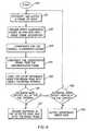
- Fig. 6there is shown a block flow diagram for the basic operational functionality for eye coordinate detection using the apparatus of Fig. 3.
- the initial assumptionis that the video camera 14 is live, capturing images when the face coordinate detection ensues.
- a color frame of video with ambient illuminationis saved S21 to the storage 34.
- the illumination source 12is triggered so that light is emitted and the next color video frame S22 is captured with an additional illumination.
- the captured framesare compensated S23 for the overall illumination change between the two captured frames to obtain a compensated frame.
- the compensated frameis subtracted S24 from an uncompensated frame of the two captured frames to obtain a color compensated difference image.
- the uncompensated framecan be either the frame bearing the ambient illumination or the frame bearing the additional illumination.
- the compensated color difference imageis scanned for any pairs of regions that have high intensity pixel values, particularly in at least one color channel S25, especially when the location of human eyes are determined, the method scans for pairs of regions that have high intensity pixel values, particularly in the red channel. In the case that animal eyes are to be located in a captured image frame, the method scans for regions of high intensity values particularly in the green channel.
- the high intensity region pairsmay be further processed to determine if they have the expected color, size, shape, structure, and spacing to plausibly represent the eye locations on a human face S26. If these conditions are satisfied, the pixel pair coordinates of the centers of the regions of high intensity pixel value corresponding to the centers of the pupil regions within the image frame are recorded together with the captured image S27.
- the digital camera 40comprises an illumination source 12 and electronic means 26.
- the electronic means 26includes a central processing unit 44 and a memory 46.
- the digital camera 40is provided with an optical lens 20 which defines an optical axis 22.
- the optical lens 20 and an image taking sensor 48are aligned on the optical axis 22.
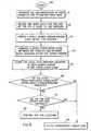
- initiation S30 of the processtwo color frames of an image scene are captured with minimum delay in between to minimize optical registration error.
- One frame S32is captured with an ambient illumination and the other frame is captured S31 with an additional camera triggered illumination.
- a compensated color difference imageis obtained by determining S34 the difference between the compensated image and an uncompensated image.
- the compensated color difference imageis then scanned S35 for regions of high intensity pixel value in at least one color channel.
- the eye-defect to be detectedcan be the red-eye effect, known from human eyes or a yellow-eye or green-eye effect as known from animal eyes.
- the compensated color difference imagehas to be scanned for regions of high intensity pixel value in the red channel.
- the compensated color difference imagehas to be scanned for regions of high intensity pixel value in the green channel.
- the eye-defect correctionmay be performed automatically in the digital camera 40.
- the usercan select to record S37 the spatial coordinates of the eye-defect regions along with the captured eye-defect image in the memory 46 of the digital camera.
- the correction for the eye-defectis performed in the photofinishing lab. In case the detected eye regions do not satisfy all of the eye criteria S38, the detection procedure will be started again. An error code will be outputted if none of the eye criteria is detected S39.
- the photographic film camera 50comprises an illumination source 12, which in one embodiment is a flash light emitting unit. Additionally, electronic means 26 are provided, which include a camera built in central processing unit 52, a memory 54 for temporary storing and recording means 56. The recording means are designed to record information on a photographic film 58 inside the camera 50. For capturing the image frames the camera 50 is provided with an optical lens 20 which defines an optical axis 22. ' The photographic film 58 and the optical lens 20 are aligned on the optical axis 22. Prior to the photographic film 58, a shutter 60 is located which allows the exposure of the photographic film 58.
- the camera 50has a built-in image sensor 62 which is located aside from the optical axis 22.
- a semi-transparent mirror 64is tilted at an angle of 45° with respect to the optical axis 22 in order to direct light from the image scene simultaneously onto the photographic film 58 and onto the image sensor 62.
- the operation steps of the photographic film camera 50are also illustrated in Fig. 7.
- the camerawill capture an image scene and thereby expose the photographic film 58 with a frame of the image scene bearing the camera triggered illumination.
- the image sensor 62is exposed with the same frame and the data representing the frame are stored in the memory 54.
- a further frame of the image scenesis captured with a minimum delay in between to minimize spatial registration error.
- This frameis captured with an ambient illumination and the light coming from this frame is used solely to expose the image sensor 62.
- the data representing the frameis stored also in the memory 54.
- Software or firmware residing in said memory 54 of said photographic film camera 50performs the brightness compensation, differencing and confirmation operations in the central processing unit 52.
- a detailed description of the process performed in the central processing unit 52is already mentioned in the paragraph describing the process in the digital camera 40.
- the data corresponding to the center of each of the eye-defect regionis recorded on the photographic film 58 inside the camera 50.
- the photographic film 58 and the camera 50are a film and camera from the Advanced Photo System.
- the recording of the datais a magnetic recording in the magnetic layer of the exposed photographic film 58.
- the photographic film camera 50provides recording means 56 which can record in the magnetic layer of the photographic film 58.
- the following descriptionis limited to one procedure of capturing frames of an image scene.
- the first picture or image frameis captured with the camera triggered illumination
- the second picture or image frameis captured with an ambient illumination.
- This method or procedureis particularly advantageous for a digital camera or a film camera: (1) the spatial registration error is minimized to benefit the differencing operation; (2) the flash unit of the camera will not be recharged in time for second firing; and (3) the non-flash image is captured and buffered only as needed.
- the illumination compensation step S23(see Fig. 6), or S33 (see Fig. 7) is performed in the following fashion.
- the following descriptionshows, that the first image is captured with ambient illumination and the second image is captured together with a camera triggered illumination.
- M 1 ( k )denotes the global mean of the kth color component of L 1 and Z is the size of the image.
- Other variablesare defined in analogy.
- a color difference imageis obtained by taking the difference between the compensated non-illuminated frame and the frame bearing the additional illumination.
- the selected sequenceshould not be regarded as a limitation.
- D x , y , kL 2 ( x , y , k ) - L 1 ( x , y , k ) + M 2 k - M 1 k
- D ( x, y, k )denotes the difference in the kth color component for a pixel at the coordinate of ( x, y ).
- Equation 3When there are multiple people at different distances or angles with respect to the illumination source, the illumination change is not uniform across the image. In this case, the compensation in Equation 3 should be performed based on local mean estimates of the log image.
- M 1 ( x, y, k )denotes the local mean of the kth color component of L 1
- N ( x, y )denotes a local window centered around the current pixel at the coordinate of ( x, y )
- ZNis the size of the local window.
- the following rulescan be used to locate the pair of pupil regions (the rules are used for detecting the eye-defect known as the red eye-effect): D x , y , red > ⁇ ⁇ D x , y , blue D x , y , red > ⁇ ⁇ D x , y , green D x , y , red > ⁇ where ⁇ is set to 2.0 and ⁇ is set to 50 in this embodiment for the color difference image converted back to the original video metric.
- the operations defined by equations 5 to 7can also be performed in the log image metric. Equations 5 and 6 ensure that there is significant higher increase in the red component relative to the other color components. Equation 7 ensures that the absolute increase in red component is significant.
- the coordinates of the pupils, as well as their sizesare extracted and stored. If multiple faces are present in the image, multiple pairs of pupils are detected. In case other eye-defects have to be detected or located than the red eye-effect (e.g. for "green eyes” or “yellow eyes” in animals), the equations 5 through 7 have to be amended with respect to the green color channel. In principle, this method can be generalized to detect any significant local changes in one or more color components.
- the eye confirmation step S26(see Fig. 6), or S36 (see Fig. 7) includes the following steps as disclosed in Fig. 8.
- This stepis mainly used to ensure the presence of the eye in order to limit false positive detection.
- the size and orientation of the eyesare estimated based on the spacing of the pair.
- the estimated sizeis checked with respect to the pupil size S41.
- a block of imageis cut out after adjusting for size and orientation with respect to a pre-defined eye template S42.
- a plurality of such blocks of imagecan be extracted within a small search window around the initial pupil position S43.
- a cross-correlation scoreis computed between the pre-defined template and an image block centered within the small search window S44.
- a local peak of cross-correlationis located within the search window S45.
- the center of the pupilmay coincide with the center of the eye in some cases. Therefore, depending on each application, a refined eye location can be obtained based on the local peak of cross-correlation.
- the center of the pupilis of interest.
- the center of the eyeis more desirable. If the local peaks do not have a cross-correlation score above a pre-defined threshold S46, an appropriate error code is output S49. Otherwise, the eye pair is further checked using a set of eye-pair criteria to ensure the presence of eyes. In particular, an intensity profile that goes through the centers of both eyes is extracted and smoothed. This profile is checked for the typical peaks and valleys that correspond to the main structure of eyes and the nose ridge between the eyes S47. If the eye-pair criteria are satisfied, the eye location is confirmed S48. Otherwise, an appropriate error code is output S49.
- the illumination source 12can be a flash unit mounted on or built into the film or digital camera.
- an infra-red (IR) illumination sourcecan be used.
- an IR sourceis used for auto-focusing and therefore can be used for red-eye generating and detection.
Landscapes
- Engineering & Computer Science (AREA)
- Physics & Mathematics (AREA)
- General Physics & Mathematics (AREA)
- Theoretical Computer Science (AREA)
- Computer Vision & Pattern Recognition (AREA)
- Human Computer Interaction (AREA)
- General Health & Medical Sciences (AREA)
- Ophthalmology & Optometry (AREA)
- Health & Medical Sciences (AREA)
- Multimedia (AREA)
- Studio Devices (AREA)
- Image Analysis (AREA)
- Processing Of Color Television Signals (AREA)
- Stroboscope Apparatuses (AREA)
- Eye Examination Apparatus (AREA)
- Image Processing (AREA)
Description
- The invention relates generally to the field of digital image processing, and in particular detecting human eyes or even animal eyes in digital images. More specifically, the invention relates to a method and apparatus for fast and accurate eye detection by taking advantage of the red-eye effect, in case human beings are captured by the apparatus. Animal eyes may be detected by taking advantage of the eye-defect in images captured together with a flash light. In case of animal eyes the regions of an image showing the eye-defect are usually visible as bright green or yellow spots in the captured image frame.
- Additionally, the invention relates to a method and apparatus for fast and automatic correction of eye-defects in captured image frames.
- The increased use of computers in many applications has drawn increasing focus on improving the man-machine interface. It is the desire of many applications to locate the face of the user, then to process it to robustly identify the person (for entitlement benefits recipients, for national border crossings or secure area entry verification, as a replacement for the ubiquitous PIN numbers, etc.). The algorithms for facial recognition have dramatically improved in recent years and are now sufficiently robust for many applications. The weak part of the system is the face detection and location front-end system. Other applications for facial imaging beyond identification are growing in interest, in particular perceptual computing, such as discerning a reaction or emotion from a user's face. This would enable computer-driven systems to be more responsive, like a human. Again, these algorithms will be limited by the weaknesses in face detection and location.
- When flash illumination is used during the capture of an image that contains sizable human faces, the pupils of people sometimes appear red because the light is partially absorbed by capillaries in the retina. As illustrated in Fig. 1, the
light rays 70 from theflash illumination source 12 enter theeye 2 through theeye lens 3, and form an image 12a of theillumination source 12 onretina 4. The eye-defect in captured images, known as the "red-eye effect" is mostly seen with human eyes. In case animals are captured, the eye-defect will show a bright green or yellow color. Animal eyes are generally more difficult to detect for pattern recognition algorithms due to the large variations in animal facial structure, complexion, hair and structure of the eyes itself. - Referring now to Fig. 2, the
light rays 80 reflected from theretina 4 exit theeye 2 through theeye lens 3, and finally enter thecamera lens 5. If thecamera lens 5 is placed close to theillumination source 12, the red-eye effect will be maximized. In other words, the amount of red-eye or eye-defect being observed increases as theillumination source 12 gets closer to anoptical axis 22 defined by the camera lens 5 (see also Fig. 3). - The general technique for red-eye reduction in cameras has been to impact two parameters: (a) Reduce the pupil diameter of the subject, for example by emitting a series of small pre-flashes prior to capturing the desired image with full illumination; and, (b) Increase the flash to lens separation, so that the illumination impinging on the subject's eyes is reflected at an angle that misses the taking lens.
- A number of U. S. Patents reflect the art prior to this invention. Each will be discussed:
- U. S. Patent 5,570,434, issued October 29, 1996 to Badique, entitled "Circuit Arrangement for Recognizing A Human Face", describes a circuit for recognizing a human face in a sequence of video images. The circuit includes the steps of subtracting two consecutive image frames and using the areas of difference to determine if there is a moving object. The difference map receives further post-processing, culminating in a convolution to determine if a head and shoulders feature set is present in the scene.
- U. S. Patent 5,680,481, issued October 21, 1997 to Prasad et al., entitled "Facial Feature Extraction Method and Apparatus for a Neural Network Acoustic and Visual Speech Recognition System", describes another approach to facial feature identification and extraction. In this patent, the variation in gray scale tones from a dull frontal face image are used to locate the eyes and mouth by thresholding the pixel values and finding centroids of the three areas.
- Many other prior art documents deal more specifically with eye or gaze tracking, or iris recognition methods or, face matching methods.
- U. S. Patent 5,325,133, issued June 28, 1994 to Adachi, entitled "Device for Measuring a Retina Reflected Light Amount and a Gaze Detecting Apparatus Using the Same" describes a device for measuring reflected light from a retina and detecting the direction in which the user is looking with an apparatus. This apparatus directs three sources of infrared emission, located at three different positions, toward a user's eyes. The system locates the pupils by pattern recognition or by red-eye ("detecting the frequency components corresponding to hemoglobin which is abundantly contained in the light reflected by the retina"). It then processes the retinal reflection based on the displacement angles to determine where the user's gaze is directed. Thus, the apparatus functionality is keyed to computing the gaze angle from the three dimensional angular measurements, instead of locating eyes. This art does not mention the issue of spacing between emission source and image capture device. It teaches away from the current invention by its dependence on measuring angular separation between emission source and image pick-up source for a minimum of three emitter/detector pairs.
- U. S. Patent 5,231,674 issued July 27, 1993 to Cleveland et al., entitled "Eye Tracking Method and Apparatus" describes a system to determine the direction that a person is gazing, determining the point at which he is gazing, or measuring the motion of his eye. The outputs of this apparatus are locations of eye features such as edge coordinates between the pupil and iris of the eye and of the center coordinates of light reflections off the cornea of the eye. An image intensity profile taken through a cross section of the eye iris, pupil (illuminated using the bright-eye effect and the corneal reflection is extracted knowing the size of the eye, inferred from the distance between the eye and the cameras). Then, the extracted profile is smoothed. The peak region (defined by a set of thresholds) near the center of the smoothed profile is detected as the corneal region. Typically the relative intensities of the iris and the pupil are not sufficiently different to make the image processing easy. Therefore, the bright-eye effect is used in this method and apparatus to increase the contrast ratio between the pupil and its surrounding iris. Consequently, the contrast ratio between the iris and the bright pupil in the camera image can be made significantly greater than the contrast ratio between the iris and a dark pupil. With the increased contrast ratio, image processing algorithms can locate the pupil edges and center more reliably and accurately for the particular eye gaze-tracking application. It would be noted that this method and apparatus assumes known eye location and eye size (on the camera optical axis and at a fixed distance) and is designed to track the eye gaze for speech impaired and physically handicapped persons. Moreover, this method and apparatus uses temporal changes in monochrome images and, thus, no color information.
- U. S. Patent 5,432,863 issued July 11, 1995 to Benati et al., entitled "Automated Detection and Correction of Eye Color Defects Due to Flash Illumination" describes a means to automatically detect and correct red-eye defects due to flash illumination in still images. The method includes means for determining whether a still image artifact is truly a red-eye problem based on shape, coloration, and brightness.
- European Patent Application Publication 0 596 868 A2 discloses a method for determining the position of eyes within a frame of captured image data, which includes the steps of: capturing first and second frames of an image scene, wherein said first frame is captured with ambient illumination and said second frame is captured with an additional illumination; storing said first and second frames of said image scene in a memory; determining a difference image; extracting one or more pairs of features; and outputting data of centric pixel pair coordinates of said features.
- It is an object of this invention to provide a method for determining the position of eyes within a captured image frame and thereby overcoming one or more problems as set forth above.
- In a method of the present invention, the position of eyes within a frame of captured image data are determined. Steps of the method comprise:
- capturing first and second frames of an image scene, wherein said first frame is captured with ambient illumination and said second frame is captured with an additional illumination; storing said first and second frames of said image scene in a memory; determining a difference image; extracting one or more pairs of features; and outputting data of centric pixel pair coordinates of said features. The steps are further characterized as:
- capturing first and second color frames of an image scene wherein said first frame is captured with an ambient illumination and said second frame is captured with an additional illumination;
- storing said first and second frames of said image scene in a memory;
- compensating at least one of said first and second frames for the overall illumination change between said first and second frames to obtain a compensated frame;
- determining the difference between said compensated frame and one of said first and second frames to obtain a compensated color difference image;
- scanning said compensated color difference image and determining pairs of regions of high intensity pixel value in at least one color channel, said high intensity being relative to other color channels; and
- outputting the data of pixel pair coordinates wherein each coordinate corresponds to a center of each region of high intensity pixel value in said color channel within said at captured image scene.
- A futher object of the invention is to provide an apparatus capable of determining the position of eyes within captured image data. The apparatus comprises: means for capturing two consecutive frames of an image scene, said means being provided with an optical lens defining an optical axis; means for storing the data of said captured frames; an illumination source illuminating one of said captured frames of said image scene wherein said illumination source is positioned as close as possible to said optical axis; and electronic means: for determining a difference image, for extracting one or more pairs of features, and for outputting data of a centric pixel their accordance of said features. The apparatus is further characterized as:
- means for capturing first and second color frames of an image scene wherein said first frame is captured with an ambient illumination and said second frame is captured with an additional illumination;
- means for storing said first and second frames of said image scene in a memory;
- means for compensating at least one of said first and second frames for the overall illumination change between said first and second frames to obtain a compensated frame;
- means for determining the difference between said compensated frame and one of said first and second frames to obtain a compensated color difference image;
- means for scanning said compensated color difference image and determining pairs of regions of high intensity pixel value in at least one color channel, said high intensity being relative to other color channels; and
- means for outputting the data of pixel pair coordinates wherein each coordinate corresponds to a center of each region of high intensity pixel value in said color channel within said at captured image scene.
- This invention describes electronics for imaging a consumer's face and providing an output video stream as well as the coordinates of the eyes, if a face is present in the image frame. This invention will describe the application of a unique combination of conventional technology to deliver inexpensively and robustly the eye coordinates.
- It is however, the novelty of this invention to take advantage of the physical cause of the red-eye effect and use it to facilitate fast and accurate eye detection. Accurate eye detection will enable enhancement and manipulation of images containing one or more human faces. For example, red-eye correction can be reliably performed.
- These and other aspects, objects, features, and advantages of the present invention will be more clearly understood and appreciated from a review of the following detailed description of the preferred embodiments and appended claims, and by reference to the accompanying drawings.
- The present invention has the following advantages:
- 1. technique quickly determines the location of eyes in an inexpensive and robust manner; and
- 2. technique enables eye-defect free photography.
- Fig. 1 is an illustration of how the light rays from an illumination source get into individual's eyes and form an image of the illumination source on the retina;
- Fig. 2 is an illustration of how the light rays reflected from the retina get into a camera's lens mounted close to the illumination source;
- Fig. 3 is an illustration of an eye detection apparatus;
- Fig. 4 is an illustration of an eye-defect free digital camera;
- Fig. 5 is an illustration of an eye-defect free photographic film camera;
- Fig. 6 is a block flow diagram representing the operating functionality of the apparatus as disclosed in the embodiment of Fig. 3;
- Fig. 7 is a block flow diagram representing the operating functionality of the camera embodiments shown in Figs. 4 and 5; and
- Fig. 8 is a block flow diagram of the eye location confirmation operations.
- To facilitate understanding of the invention, identical reference numerals have been used, where possible, to designate identical elements that are common to the figures.
- The configuration of an apparatus for determining the position of eyes within a captured image frame is depicted in Fig. 3. This system can be used for a number of applications, including user identification (e.g., for ATM), user monitoring (e.g., for checking the alertness of car drivers), and pose optimization for ID photo taking (with audio feedback instructions generated by the photo-taking system when red-eye effect is maximized). In particular, eye location can be used to perform spatial normalization of the face for face recognition, model-based face image compression, etc. In addition, eye movement and iris motion can be monitored to check if a driver is still alert. The
apparatus 10 includes anillumination source 12 which is attached to means 14 for capturing at least two image frames of an image scene. In the embodiment as shown in Fig. 3, themeans 14 for capturing is a video camera. Adriver circuit 16 is attached to the video camera and aframe grabber 18 is positioned in the video camera. Additionally the video camera is provided with anoptical lens 20 which defines anoptical axis 22. The video camera is connected by anelectric cable 24 toelectronic means 26. The electronic means comprises amonitor 28, acomputer 30, akeyboard 32, a storage or amemory 34, and aprinter 36. Theillumination source 12 may include a lamp or an infra-red firing device, power supply and triggering circuit (not shown). A key element of the configuration is to use the smallest spacing between theillumination source 12 and theoptical lens 20. In other words, theillumination source 12 should be placed as close to the camera'soptical axis 22 as possible. This will give the narrowest retinal reflection angle and thus the strongest eye-defect to make a robust pupil location feature. On the contrary, common practice in conventional camera design is to make the angle between these components as large as possible to minimize the reflection which causes an eye-defect in images. - The present invention utilizes the red-eye phenomenon to serve as a feature for locating the coordinates of human eyes within a captured frame of an image scene. On the other hand even animals' eyes can be located within an image scene. In this case the eye-defect is not a red-eye effect, as with human eyes, instead it is of green or yellow color. In order to detect animals' eyes within an image scene, the
apparatus 10 has to scan the image for bright regions in the green channel. - Referring now to Fig. 6, there is shown a block flow diagram for the basic operational functionality for eye coordinate detection using the apparatus of Fig. 3. The initial assumption is that the
video camera 14 is live, capturing images when the face coordinate detection ensues. After pressing start S20 first, a color frame of video with ambient illumination is saved S21 to thestorage 34. Next, theillumination source 12 is triggered so that light is emitted and the next color video frame S22 is captured with an additional illumination. The captured frames are compensated S23 for the overall illumination change between the two captured frames to obtain a compensated frame. The compensated frame is subtracted S24 from an uncompensated frame of the two captured frames to obtain a color compensated difference image. The uncompensated frame can be either the frame bearing the ambient illumination or the frame bearing the additional illumination. The compensated color difference image is scanned for any pairs of regions that have high intensity pixel values, particularly in at least one color channel S25, especially when the location of human eyes are determined, the method scans for pairs of regions that have high intensity pixel values, particularly in the red channel. In the case that animal eyes are to be located in a captured image frame, the method scans for regions of high intensity values particularly in the green channel. The high intensity region pairs may be further processed to determine if they have the expected color, size, shape, structure, and spacing to plausibly represent the eye locations on a human face S26. If these conditions are satisfied, the pixel pair coordinates of the centers of the regions of high intensity pixel value corresponding to the centers of the pupil regions within the image frame are recorded together with the captured image S27. If the conditions are not completely satisfied, alternative error correcting measures may be taken. If no high intensity regions in the compensated difference image are detected, that state is indicated S29 to theelectronic means 26. If the conditions are partially satisfied, that state is indicated to thecomputer 30, which will send control signals to thedriver circuitry 16 to capture another set of images and test again S28. - Referring now to Fig. 4, the function of eye-defect free picture taking can be enabled by a
user input control 42 which is part of adigital camera 40. Thedigital camera 40 comprises anillumination source 12 andelectronic means 26. The electronic means 26 includes acentral processing unit 44 and amemory 46. For capturing the individual frames of an image scene, thedigital camera 40 is provided with anoptical lens 20 which defines anoptical axis 22. Theoptical lens 20 and animage taking sensor 48 are aligned on theoptical axis 22. - The operation steps are illustrated in Fig. 7. After initiation S30 of the process, two color frames of an image scene are captured with minimum delay in between to minimize optical registration error. One frame S32 is captured with an ambient illumination and the other frame is captured S31 with an additional camera triggered illumination.
- These two images are stored in the
memory 46 where software or firmware residing in thecamera memory 46 performs the brightness compensation S33, differencing and confirmation operations in thecentral processing unit 44. A compensated color difference image is obtained by determining S34 the difference between the compensated image and an uncompensated image. The compensated color difference image is then scanned S35 for regions of high intensity pixel value in at least one color channel. As mentioned above, the eye-defect to be detected can be the red-eye effect, known from human eyes or a yellow-eye or green-eye effect as known from animal eyes. In order to detect the red-eye effect, the compensated color difference image has to be scanned for regions of high intensity pixel value in the red channel. To locate animal eyes within an image frame, the compensated color difference image has to be scanned for regions of high intensity pixel value in the green channel. Once the data of the pixel pair coordinates are obtained, and the detected region does satisfy S36 all of the eye criteria, the eye-defect correction may be performed automatically in thedigital camera 40. Furthermore, the user can select to record S37 the spatial coordinates of the eye-defect regions along with the captured eye-defect image in thememory 46 of the digital camera. The correction for the eye-defect is performed in the photofinishing lab. In case the detected eye regions do not satisfy all of the eye criteria S38, the detection procedure will be started again. An error code will be outputted if none of the eye criteria is detected S39. - Referring now to Fig. 5, the function of eye-defect free picture taking is implemented in a
photographic film camera 50. A user can enable the function by auser input control 42. Thephotographic film camera 50 comprises anillumination source 12, which in one embodiment is a flash light emitting unit. Additionally,electronic means 26 are provided, which include a camera built incentral processing unit 52, amemory 54 for temporary storing and recording means 56. The recording means are designed to record information on aphotographic film 58 inside thecamera 50. For capturing the image frames thecamera 50 is provided with anoptical lens 20 which defines anoptical axis 22. ' Thephotographic film 58 and theoptical lens 20 are aligned on theoptical axis 22. Prior to thephotographic film 58, ashutter 60 is located which allows the exposure of thephotographic film 58. Additionally thecamera 50 has a built-inimage sensor 62 which is located aside from theoptical axis 22. Asemi-transparent mirror 64 is tilted at an angle of 45° with respect to theoptical axis 22 in order to direct light from the image scene simultaneously onto thephotographic film 58 and onto theimage sensor 62. - The operation steps of the
photographic film camera 50 are also illustrated in Fig. 7. After selecting the function for eye-defect free picture taking, the camera will capture an image scene and thereby expose thephotographic film 58 with a frame of the image scene bearing the camera triggered illumination. Parallel to the exposure of thephotographic film 58, theimage sensor 62 is exposed with the same frame and the data representing the frame are stored in thememory 54. A further frame of the image scenes is captured with a minimum delay in between to minimize spatial registration error. This frame is captured with an ambient illumination and the light coming from this frame is used solely to expose theimage sensor 62. The data representing the frame is stored also in thememory 54. Software or firmware residing in saidmemory 54 of saidphotographic film camera 50, performs the brightness compensation, differencing and confirmation operations in thecentral processing unit 52. A detailed description of the process performed in thecentral processing unit 52 is already mentioned in the paragraph describing the process in thedigital camera 40. - After the electronic means 26 in the
photographic film camera 50 has located and determined the pairs of regions of high intensity pixel value in at least one color channel, the data corresponding to the center of each of the eye-defect region is recorded on thephotographic film 58 inside thecamera 50. In one embodiment thephotographic film 58 and thecamera 50 are a film and camera from the Advanced Photo System. The recording of the data is a magnetic recording in the magnetic layer of the exposedphotographic film 58. Thephotographic film camera 50 provides recording means 56 which can record in the magnetic layer of thephotographic film 58. - The following description is limited to one procedure of capturing frames of an image scene. The first picture or image frame is captured with the camera triggered illumination, and the second picture or image frame is captured with an ambient illumination. Nevertheless, the above is not considered as a limitation since it is obvious to any person skilled in the art to carry out the above procedure in that the first captured image frame bears the ambient illumination. This method or procedure is particularly advantageous for a digital camera or a film camera: (1) the spatial registration error is minimized to benefit the differencing operation; (2) the flash unit of the camera will not be recharged in time for second firing; and (3) the non-flash image is captured and buffered only as needed.
- More specifically the illumination compensation step S23 (see Fig. 6), or S33 (see Fig. 7) is performed in the following fashion. The following description shows, that the first image is captured with ambient illumination and the second image is captured together with a camera triggered illumination. Each image is converted into a log image using Equation 1:

whereI1(x, y, k) denotes the intensity value of the kth color component of a pixel at the coordinate of (x, y), andL1(x, y, k) denotes the log-transformed intensity value. Other variables are defined in analog. Then, the global mean of each log image is computed:
whereM1(k) denotes the global mean of the kth color component ofL1 and Z is the size of the image. Other variables are defined in analogy. - Then a color difference image is obtained by taking the difference between the compensated non-illuminated frame and the frame bearing the additional illumination. Again, the selected sequence should not be regarded as a limitation.

whereD(x, y, k) denotes the difference in the kth color component for a pixel at the coordinate of (x, y). - When there are multiple people at different distances or angles with respect to the illumination source, the illumination change is not uniform across the image. In this case, the compensation in
Equation 3 should be performed based onlocal mean estimates of the log image.
whereM1 (x, y, k) denotes thelocal mean of the kth color component ofL1, andN(x, y) denotes a local window centered around the current pixel at the coordinate of (x, y), and ZN is the size of the local window. - The following rules can be used to locate the pair of pupil regions (the rules are used for detecting the eye-defect known as the red eye-effect):


where α is set to 2.0 and β is set to 50 in this embodiment for the color difference image converted back to the original video metric. The operations defined byequations 5 to 7 can also be performed in the log image metric.Equations 5 and 6 ensure that there is significant higher increase in the red component relative to the other color components. Equation 7 ensures that the absolute increase in red component is significant. The coordinates of the pupils, as well as their sizes are extracted and stored. If multiple faces are present in the image, multiple pairs of pupils are detected. In case other eye-defects have to be detected or located than the red eye-effect (e.g. for "green eyes" or "yellow eyes" in animals), theequations 5 through 7 have to be amended with respect to the green color channel. In principle, this method can be generalized to detect any significant local changes in one or more color components. - In particular, the eye confirmation step S26 (see Fig. 6), or S36 (see Fig. 7) includes the following steps as disclosed in Fig. 8. This step is mainly used to ensure the presence of the eye in order to limit false positive detection. For each extracted pupil pair, the size and orientation of the eyes are estimated based on the spacing of the pair. The estimated size is checked with respect to the pupil size S41. Next, a block of image is cut out after adjusting for size and orientation with respect to a pre-defined eye template S42. A plurality of such blocks of image can be extracted within a small search window around the initial pupil position S43. A cross-correlation score is computed between the pre-defined template and an image block centered within the small search window S44. Then, a local peak of cross-correlation is located within the search window S45. Note that the center of the pupil may coincide with the center of the eye in some cases. Therefore, depending on each application, a refined eye location can be obtained based on the local peak of cross-correlation. For red-eye removal, the center of the pupil is of interest. On the other hand, for spatial normalization of the face or pose estimation, the center of the eye is more desirable. If the local peaks do not have a cross-correlation score above a pre-defined threshold S46, an appropriate error code is output S49. Otherwise, the eye pair is further checked using a set of eye-pair criteria to ensure the presence of eyes. In particular, an intensity profile that goes through the centers of both eyes is extracted and smoothed. This profile is checked for the typical peaks and valleys that correspond to the main structure of eyes and the nose ridge between the eyes S47. If the eye-pair criteria are satisfied, the eye location is confirmed S48. Otherwise, an appropriate error code is output S49.
- The
illumination source 12 can be a flash unit mounted on or built into the film or digital camera. For an apparatus such as illustrated in Fig. 3, an infra-red (IR) illumination source can be used. For certain digital or film cameras, an IR source is used for auto-focusing and therefore can be used for red-eye generating and detection. - 2
- eye
- 3
- eye lens
- 4
- retina
- 5
- camera lens
- 10
- apparatus
- 12
- illumination source
- 12a
- image of the illumination source
- 14
- means for capturing
- 16
- driver circuit
- 18
- frame grabber
- 20
- optical lens
- 22
- optical axis
- 24
- electric cable
- 26
- electronic means
- 28
- monitor
- 30
- computer
- 32
- keyboard
- 34
- storage or memory
- 36
- printer
- 40
- digital camera
- 42
- user input control
- 44
- central processing unit
- 46
- memory
- 48
- image taking sensor
- 50
- photographic film camera
- 52
- central processing unit
- 54
- memory
- 56
- recording means
- 58
- photographic film
- 60
- shutter
- 62
- image sensor
- 64
- semi-transparent mirror
- 70
- light rays from the illumination source
- 80
- light rays reflected from retina


Claims (14)
- A method for determining the position of eyes (2) within a frame of captured image data comprising the steps of: capturing first and second color frames of an image scene, wherein said first color frame is captured with ambient illumination and said second color frame is captured with an additional illumination; storing said first and second color frames of said image scene in a memory; determining a difference image; extracting one or more pairs of features; and outputting data of centric pixel pair coordinates of said features; said method being furthercharacterized as:capturing said first color frame of the image scene, then immediately capturing said second color frame of the image scene, wherein said first color frame is captured with an ambient illumination and said second color frame is captured with an additional illumination,storing said first and second color frames of said image scene in a memory (46);compensating (S23,S33) at least one of said first and second color frames for the overall illumination change between said first and second color frames to obtain a single compensated frame;determining (S24,S34) the difference between said compensated frame and one of said first and second color frames to obtain a compensated color difference image;scanning (S25,S35) said compensated color difference image and determining pairs of regions of high intensity pixel value in at least one color channel, said high intensity being relative to other color channels; andoutputting the data of pixel pair coordinates wherein each coordinate corresponds to a center of each region of high intensity pixel value in said color channel.
- The method according to claim 1 furthercharacterized as selecting a function of a digital camera (40) for eye-defect free picture taking, prior to said compensating.
- The method according to claim 1 or 2, wherein said compensating step comprises:a) converting the value of each pixel in said first and second color frames into log metric to provide converted images;b) calculating the mean log the intensity value of each of said converted images;c) adding the difference between said mean log intensity values to the converted image corresponding to the subtrahend of said difference; andd) converting said compensated log image to the inverse log metric to obtain a compensated frame.
- The method according to claim 1 or 2, wherein said predetermined pairs of regions of said high intensity pixel value, are processed according to color, size, shape structure, in the red channel for human eyes and the green channel for animal eyes.
- The method according to claim 1 or 2, wherein said predetermined pairs of regions of said high intensity pixel value, are processed in the red channel for human eyes, according to color, size, shape structure, and spacing.
- The method according to claim 1 or 2 wherein the outputting step comprises recording the pixel coordinates of the center of said regions of said high intensity pixel value.
- The method according to claim 1 or 2 wherein said color frames of said image scene are consecutive pictures of a video image stream.
- The method of claim 2 wherein, based on said selecting, the digital camera (40) performs an automatic eye-defect correction of the captured image scene.
- The method of claim 2 wherein, based on said selecting, the digital camera (40) stores the data of the color frame bearing said camera triggered illumination along with said data of pixel pair coordinates.
- An apparatus for determining the position of eyes within captured image data, said apparatus comprising: means for capturing two consecutive color frames of an image scene, said means being provided with an optical lens defining an optical axis; means for storing the data of said captured color frames; an illumination source illuminating one of said captured color frames of said image scene wherein said illumination source is positioned as close as possible to said optical axis; and electronic means: for determining a difference image, for extracting one or more pairs of features, and for outputting data of a centric pixel in accordance of said features; said apparatus being furthercharacterized as:means for capturing said first color frame of the image scene, then immediately capturing said second color frame of the image scene, wherein said first color frame is captured with an ambient illumination and said second color frame is captured with an additional illumination;means for storing said first and second color frames of said image scene in a memory;means for compensating at least one of said first and second color frames for the overall illumination change between said first and second color frames to obtain a single compensated frame;means for determining the difference between said compensated frame and one of said first and second color frames to obtain a compensated color difference image;means for scanning said compensated color difference image and determining pairs of regions of high intensity pixel value in at least one color channel, said high intensity being relative to other color channels; andmeans for outputting the data of pixel pair coordinates wherein each coordinate corresponds to a center of each region of high intensity pixel value in said color channel.
- The apparatus according to claim 10 wherein the capturing means is a video camera capturing consecutive said color frames of an image scene; the illumination source is a flash light emitting source triggering direct illumination in synchronization with the capturing of the second image frame of said image scene; and the electronic means is a computer (30) to which a keyboard (32), a monitor (28), an external storage (34), and a printer (36) are connected.
- The apparatus according to claim 10 further comprising a user input control (42) for initiating the eye-defect correction function.
- The apparatus according to claim 10 wherein said means for capturing said second color frame of an image scene is furthercharacterized as means for exposing photographic film (58).
- The apparatus according to claim 13 wherein said means for capturing is furthercharacterized as a semi-transparent mirror (64) located in said optical axis (22) in order to simultaneously illuminate said photographic film (58) and an image sensor (62), said illumination of said photographic film (58) being controlled by a shutter (60), positioned in front of said photographic film (58).
Applications Claiming Priority (2)
| Application Number | Priority Date | Filing Date | Title |
|---|---|---|---|
| US154684 | 1998-09-17 | ||
| US09/154,684US6134339A (en) | 1998-09-17 | 1998-09-17 | Method and apparatus for determining the position of eyes and for correcting eye-defects in a captured frame |
Publications (3)
| Publication Number | Publication Date |
|---|---|
| EP0989517A2 EP0989517A2 (en) | 2000-03-29 |
| EP0989517A3 EP0989517A3 (en) | 2003-01-02 |
| EP0989517B1true EP0989517B1 (en) | 2006-11-22 |
Family
ID=22552323
Family Applications (1)
| Application Number | Title | Priority Date | Filing Date |
|---|---|---|---|
| EP99202983AExpired - LifetimeEP0989517B1 (en) | 1998-09-17 | 1999-09-13 | Determining the position of eyes through detection of flashlight reflection and correcting defects in a captured frame |
Country Status (4)
| Country | Link |
|---|---|
| US (1) | US6134339A (en) |
| EP (1) | EP0989517B1 (en) |
| JP (1) | JP4583527B2 (en) |
| DE (1) | DE69934068T2 (en) |
Families Citing this family (192)
| Publication number | Priority date | Publication date | Assignee | Title |
|---|---|---|---|---|
| US6786420B1 (en) | 1997-07-15 | 2004-09-07 | Silverbrook Research Pty. Ltd. | Data distribution mechanism in the form of ink dots on cards |
| US6618117B2 (en) | 1997-07-12 | 2003-09-09 | Silverbrook Research Pty Ltd | Image sensing apparatus including a microcontroller |
| AUPO802797A0 (en) | 1997-07-15 | 1997-08-07 | Silverbrook Research Pty Ltd | Image processing method and apparatus (ART54) |
| US6879341B1 (en) | 1997-07-15 | 2005-04-12 | Silverbrook Research Pty Ltd | Digital camera system containing a VLIW vector processor |
| US6985207B2 (en) | 1997-07-15 | 2006-01-10 | Silverbrook Research Pty Ltd | Photographic prints having magnetically recordable media |
| US6624848B1 (en) | 1997-07-15 | 2003-09-23 | Silverbrook Research Pty Ltd | Cascading image modification using multiple digital cameras incorporating image processing |
| US20040160524A1 (en)* | 1997-07-15 | 2004-08-19 | Kia Silverbrook | Utilising exposure information for image processing in a digital image camera |
| US7593058B2 (en)* | 1997-07-15 | 2009-09-22 | Silverbrook Research Pty Ltd | Digital camera with integrated inkjet printer having removable cartridge containing ink and media substrate |
| US7110024B1 (en) | 1997-07-15 | 2006-09-19 | Silverbrook Research Pty Ltd | Digital camera system having motion deblurring means |
| US7714889B2 (en)* | 1997-07-15 | 2010-05-11 | Silverbrook Research Pty Ltd | Digital camera using exposure information for image processing |
| US6690419B1 (en) | 1997-07-15 | 2004-02-10 | Silverbrook Research Pty Ltd | Utilising eye detection methods for image processing in a digital image camera |
| AUPO799997A0 (en)* | 1997-07-15 | 1997-08-07 | Silverbrook Research Pty Ltd | Image processing method and apparatus (ART10) |
| US7551202B2 (en)* | 1997-07-15 | 2009-06-23 | Silverbrook Research Pty Ltd | Digital camera with integrated inkjet printer |
| US20040119829A1 (en) | 1997-07-15 | 2004-06-24 | Silverbrook Research Pty Ltd | Printhead assembly for a print on demand digital camera system |
| AUPO850597A0 (en)* | 1997-08-11 | 1997-09-04 | Silverbrook Research Pty Ltd | Image processing method and apparatus (art01a) |
| US7724282B2 (en) | 1997-07-15 | 2010-05-25 | Silverbrook Research Pty Ltd | Method of processing digital image to correct for flash effects |
| US7246897B2 (en)* | 1997-07-15 | 2007-07-24 | Silverbrook Research Pty Ltd | Media cartridge for inkjet printhead |
| US7077515B2 (en)* | 1997-07-15 | 2006-07-18 | Silverbrook Research Pty Ltd | Media cartridge for inkjet printhead |
| US7042505B1 (en) | 1997-10-09 | 2006-05-09 | Fotonation Ireland Ltd. | Red-eye filter method and apparatus |
| US7738015B2 (en) | 1997-10-09 | 2010-06-15 | Fotonation Vision Limited | Red-eye filter method and apparatus |
| US7352394B1 (en) | 1997-10-09 | 2008-04-01 | Fotonation Vision Limited | Image modification based on red-eye filter analysis |
| US7630006B2 (en) | 1997-10-09 | 2009-12-08 | Fotonation Ireland Limited | Detecting red eye filter and apparatus using meta-data |
| US6278491B1 (en)* | 1998-01-29 | 2001-08-21 | Hewlett-Packard Company | Apparatus and a method for automatically detecting and reducing red-eye in a digital image |
| US6631208B1 (en)* | 1998-05-29 | 2003-10-07 | Fuji Photo Film Co., Ltd. | Image processing method |
| AUPP702098A0 (en) | 1998-11-09 | 1998-12-03 | Silverbrook Research Pty Ltd | Image creation method and apparatus (ART73) |
| AUPQ056099A0 (en) | 1999-05-25 | 1999-06-17 | Silverbrook Research Pty Ltd | A method and apparatus (pprint01) |
| US6629795B2 (en)* | 2000-03-10 | 2003-10-07 | Sharp Kabushiki Kaisha | Image formation apparatus |
| US6728401B1 (en)* | 2000-08-17 | 2004-04-27 | Viewahead Technology | Red-eye removal using color image processing |
| AU2001290608A1 (en) | 2000-08-31 | 2002-03-13 | Rytec Corporation | Sensor and imaging system |
| DE10052201B8 (en)* | 2000-10-20 | 2005-06-30 | Carl Zeiss Meditec Ag | Method and device for identifying a patient and an operating area |
| US6895112B2 (en)* | 2001-02-13 | 2005-05-17 | Microsoft Corporation | Red-eye detection based on red region detection with eye confirmation |
| US6829384B2 (en) | 2001-02-28 | 2004-12-07 | Carnegie Mellon University | Object finder for photographic images |
| GB0107689D0 (en)* | 2001-03-28 | 2001-05-16 | Ncr Int Inc | Self service terminal |
| US6873743B2 (en)* | 2001-03-29 | 2005-03-29 | Fotonation Holdings, Llc | Method and apparatus for the automatic real-time detection and correction of red-eye defects in batches of digital images or in handheld appliances |
| US7174034B2 (en)* | 2001-04-13 | 2007-02-06 | Seiko Epson Corporation | Redeye reduction of digital images |
| US6959102B2 (en)* | 2001-05-29 | 2005-10-25 | International Business Machines Corporation | Method for increasing the signal-to-noise in IR-based eye gaze trackers |
| US7110026B2 (en)* | 2001-07-03 | 2006-09-19 | Logitech Europe S.A. | Image tagging for post processing |
| US6980691B2 (en) | 2001-07-05 | 2005-12-27 | Corel Corporation | Correction of “red-eye” effects in images |
| EP1288858A1 (en)* | 2001-09-03 | 2003-03-05 | Agfa-Gevaert AG | Method for automatically detecting red-eye defects in photographic image data |
| EP1288859A1 (en)* | 2001-09-03 | 2003-03-05 | Agfa-Gevaert AG | Method for automatic detection of red-eye defecs in photographic images |
| EP1600898B1 (en)* | 2002-02-05 | 2018-10-17 | Panasonic Intellectual Property Management Co., Ltd. | Personal authentication method, personal authentication apparatus and image capturing device |
| US7362354B2 (en)* | 2002-02-12 | 2008-04-22 | Hewlett-Packard Development Company, L.P. | Method and system for assessing the photo quality of a captured image in a digital still camera |
| US7146026B2 (en) | 2002-06-04 | 2006-12-05 | Hewlett-Packard Development Company, L.P. | Image correction system and method |
| US7177449B2 (en) | 2002-06-26 | 2007-02-13 | Hewlett-Packard Development Company, L.P. | Image correction system and method |
| US7035462B2 (en)* | 2002-08-29 | 2006-04-25 | Eastman Kodak Company | Apparatus and method for processing digital images having eye color defects |
| US7321699B2 (en) | 2002-09-06 | 2008-01-22 | Rytec Corporation | Signal intensity range transformation apparatus and method |
| US7277589B2 (en)* | 2002-09-24 | 2007-10-02 | Fujifilm Corporation | Image retouching method, apparatus, and program storage medium, image correcting method, apparatus, and program storage medium, and eye detecting and correcting method apparatus, and program storage medium |
| US7194114B2 (en)* | 2002-10-07 | 2007-03-20 | Carnegie Mellon University | Object finder for two-dimensional images, and system for determining a set of sub-classifiers composing an object finder |
| DE60327004D1 (en)* | 2002-12-11 | 2009-05-14 | Fujifilm Corp | Imaging device |
| JP2004206688A (en)* | 2002-12-12 | 2004-07-22 | Fuji Photo Film Co Ltd | Face recognition method, face image cutting out method, and imaging apparatus |
| GB0305715D0 (en)* | 2003-03-13 | 2003-04-16 | Roke Manor Research | Camera illumination system |
| US7636486B2 (en)* | 2004-11-10 | 2009-12-22 | Fotonation Ireland Ltd. | Method of determining PSF using multiple instances of a nominally similar scene |
| US8989453B2 (en) | 2003-06-26 | 2015-03-24 | Fotonation Limited | Digital image processing using face detection information |
| US7536036B2 (en) | 2004-10-28 | 2009-05-19 | Fotonation Vision Limited | Method and apparatus for red-eye detection in an acquired digital image |
| US8682097B2 (en) | 2006-02-14 | 2014-03-25 | DigitalOptics Corporation Europe Limited | Digital image enhancement with reference images |
| US9160897B2 (en) | 2007-06-14 | 2015-10-13 | Fotonation Limited | Fast motion estimation method |
| US8494286B2 (en) | 2008-02-05 | 2013-07-23 | DigitalOptics Corporation Europe Limited | Face detection in mid-shot digital images |
| US7620218B2 (en) | 2006-08-11 | 2009-11-17 | Fotonation Ireland Limited | Real-time face tracking with reference images |
| US7440593B1 (en) | 2003-06-26 | 2008-10-21 | Fotonation Vision Limited | Method of improving orientation and color balance of digital images using face detection information |
| US8417055B2 (en) | 2007-03-05 | 2013-04-09 | DigitalOptics Corporation Europe Limited | Image processing method and apparatus |
| US8989516B2 (en)* | 2007-09-18 | 2015-03-24 | Fotonation Limited | Image processing method and apparatus |
| US7792970B2 (en) | 2005-06-17 | 2010-09-07 | Fotonation Vision Limited | Method for establishing a paired connection between media devices |
| US8036458B2 (en) | 2007-11-08 | 2011-10-11 | DigitalOptics Corporation Europe Limited | Detecting redeye defects in digital images |
| US8155397B2 (en) | 2007-09-26 | 2012-04-10 | DigitalOptics Corporation Europe Limited | Face tracking in a camera processor |
| US7920723B2 (en) | 2005-11-18 | 2011-04-05 | Tessera Technologies Ireland Limited | Two stage detection for photographic eye artifacts |
| US8199222B2 (en) | 2007-03-05 | 2012-06-12 | DigitalOptics Corporation Europe Limited | Low-light video frame enhancement |
| US8180173B2 (en) | 2007-09-21 | 2012-05-15 | DigitalOptics Corporation Europe Limited | Flash artifact eye defect correction in blurred images using anisotropic blurring |
| US7587085B2 (en) | 2004-10-28 | 2009-09-08 | Fotonation Vision Limited | Method and apparatus for red-eye detection in an acquired digital image |
| US7639889B2 (en) | 2004-11-10 | 2009-12-29 | Fotonation Ireland Ltd. | Method of notifying users regarding motion artifacts based on image analysis |
| US7574016B2 (en) | 2003-06-26 | 2009-08-11 | Fotonation Vision Limited | Digital image processing using face detection information |
| US7689009B2 (en) | 2005-11-18 | 2010-03-30 | Fotonation Vision Ltd. | Two stage detection for photographic eye artifacts |
| US7565030B2 (en) | 2003-06-26 | 2009-07-21 | Fotonation Vision Limited | Detecting orientation of digital images using face detection information |
| US7970182B2 (en) | 2005-11-18 | 2011-06-28 | Tessera Technologies Ireland Limited | Two stage detection for photographic eye artifacts |
| US9129381B2 (en) | 2003-06-26 | 2015-09-08 | Fotonation Limited | Modification of post-viewing parameters for digital images using image region or feature information |
| US8170294B2 (en) | 2006-11-10 | 2012-05-01 | DigitalOptics Corporation Europe Limited | Method of detecting redeye in a digital image |
| US7616233B2 (en) | 2003-06-26 | 2009-11-10 | Fotonation Vision Limited | Perfecting of digital image capture parameters within acquisition devices using face detection |
| US8073286B2 (en)* | 2006-08-09 | 2011-12-06 | DigitalOptics Corporation Europe Limited | Detection and correction of flash artifacts from airborne particulates |
| US8948468B2 (en) | 2003-06-26 | 2015-02-03 | Fotonation Limited | Modification of viewing parameters for digital images using face detection information |
| US9692964B2 (en) | 2003-06-26 | 2017-06-27 | Fotonation Limited | Modification of post-viewing parameters for digital images using image region or feature information |
| US8896725B2 (en) | 2007-06-21 | 2014-11-25 | Fotonation Limited | Image capture device with contemporaneous reference image capture mechanism |
| US8264576B2 (en) | 2007-03-05 | 2012-09-11 | DigitalOptics Corporation Europe Limited | RGBW sensor array |
| US7317815B2 (en)* | 2003-06-26 | 2008-01-08 | Fotonation Vision Limited | Digital image processing composition using face detection information |
| US7269292B2 (en) | 2003-06-26 | 2007-09-11 | Fotonation Vision Limited | Digital image adjustable compression and resolution using face detection information |
| US7471846B2 (en) | 2003-06-26 | 2008-12-30 | Fotonation Vision Limited | Perfecting the effect of flash within an image acquisition devices using face detection |
| US8330831B2 (en) | 2003-08-05 | 2012-12-11 | DigitalOptics Corporation Europe Limited | Method of gathering visual meta data using a reference image |
| US8498452B2 (en) | 2003-06-26 | 2013-07-30 | DigitalOptics Corporation Europe Limited | Digital image processing using face detection information |
| US7844076B2 (en) | 2003-06-26 | 2010-11-30 | Fotonation Vision Limited | Digital image processing using face detection and skin tone information |
| US8593542B2 (en) | 2005-12-27 | 2013-11-26 | DigitalOptics Corporation Europe Limited | Foreground/background separation using reference images |
| US8254674B2 (en) | 2004-10-28 | 2012-08-28 | DigitalOptics Corporation Europe Limited | Analyzing partial face regions for red-eye detection in acquired digital images |
| EP2151191B1 (en)* | 2003-07-04 | 2017-02-22 | Panasonic Intellectual Property Corporation of America | Living eye judging method and device |
| EP1499111B1 (en)* | 2003-07-15 | 2015-01-07 | Canon Kabushiki Kaisha | Image sensiting apparatus, image processing apparatus, and control method thereof |
| US8520093B2 (en) | 2003-08-05 | 2013-08-27 | DigitalOptics Corporation Europe Limited | Face tracker and partial face tracker for red-eye filter method and apparatus |
| US20050031224A1 (en)* | 2003-08-05 | 2005-02-10 | Yury Prilutsky | Detecting red eye filter and apparatus using meta-data |
| US9412007B2 (en) | 2003-08-05 | 2016-08-09 | Fotonation Limited | Partial face detector red-eye filter method and apparatus |
| US8064647B2 (en)* | 2006-03-03 | 2011-11-22 | Honeywell International Inc. | System for iris detection tracking and recognition at a distance |
| US7593550B2 (en) | 2005-01-26 | 2009-09-22 | Honeywell International Inc. | Distance iris recognition |
| US8705808B2 (en)* | 2003-09-05 | 2014-04-22 | Honeywell International Inc. | Combined face and iris recognition system |
| US8442276B2 (en)* | 2006-03-03 | 2013-05-14 | Honeywell International Inc. | Invariant radial iris segmentation |
| US8090157B2 (en) | 2005-01-26 | 2012-01-03 | Honeywell International Inc. | Approaches and apparatus for eye detection in a digital image |
| US8098901B2 (en) | 2005-01-26 | 2012-01-17 | Honeywell International Inc. | Standoff iris recognition system |
| US7835572B2 (en)* | 2003-09-30 | 2010-11-16 | Sharp Laboratories Of America, Inc. | Red eye reduction technique |
| US6984039B2 (en)* | 2003-12-01 | 2006-01-10 | Eastman Kodak Company | Laser projector having silhouette blanking for objects in the output light path |
| US20050220346A1 (en)* | 2004-03-30 | 2005-10-06 | Fuji Photo Film Co., Ltd. | Red eye detection device, red eye detection method, and recording medium with red eye detection program |
| US20050248664A1 (en)* | 2004-05-07 | 2005-11-10 | Eastman Kodak Company | Identifying red eye in digital camera images |
| US7627146B2 (en)* | 2004-06-30 | 2009-12-01 | Lexmark International, Inc. | Method and apparatus for effecting automatic red eye reduction |
| US8570389B2 (en)* | 2004-07-22 | 2013-10-29 | Broadcom Corporation | Enhancing digital photography |
| US8320641B2 (en) | 2004-10-28 | 2012-11-27 | DigitalOptics Corporation Europe Limited | Method and apparatus for red-eye detection using preview or other reference images |
| US7444017B2 (en)* | 2004-11-10 | 2008-10-28 | Eastman Kodak Company | Detecting irises and pupils in images of humans |
| US7639888B2 (en) | 2004-11-10 | 2009-12-29 | Fotonation Ireland Ltd. | Method and apparatus for initiating subsequent exposures based on determination of motion blurring artifacts |
| US8503800B2 (en) | 2007-03-05 | 2013-08-06 | DigitalOptics Corporation Europe Limited | Illumination detection using classifier chains |
| US7315631B1 (en) | 2006-08-11 | 2008-01-01 | Fotonation Vision Limited | Real-time face tracking in a digital image acquisition device |
| US7809171B2 (en)* | 2005-01-10 | 2010-10-05 | Battelle Memorial Institute | Facial feature evaluation based on eye location |
| US7450756B2 (en)* | 2005-04-28 | 2008-11-11 | Hewlett-Packard Development Company, L.P. | Method and apparatus for incorporating iris color in red-eye correction |
| US7831067B2 (en)* | 2005-05-16 | 2010-11-09 | Cisco Technology, Inc. | Methods and apparatus for automated, multi-level red eye correction |
| US8374403B2 (en)* | 2005-05-16 | 2013-02-12 | Cisco Technology, Inc. | Methods and apparatus for efficient, automated red eye detection |
| US20060279745A1 (en)* | 2005-06-13 | 2006-12-14 | Wenstrand John S | Color imaging system for locating retroreflectors |
| US7747071B2 (en)* | 2005-10-27 | 2010-06-29 | Hewlett-Packard Development Company, L.P. | Detecting and correcting peteye |
| US7599577B2 (en) | 2005-11-18 | 2009-10-06 | Fotonation Vision Limited | Method and apparatus of correcting hybrid flash artifacts in digital images |
| US7664336B2 (en)* | 2006-01-26 | 2010-02-16 | Microsoft Corporation | Video noise reduction |
| JP4643715B2 (en) | 2006-02-14 | 2011-03-02 | テセラ テクノロジーズ アイルランド リミテッド | Automatic detection and correction of defects caused by non-red eye flash |
| US20070206372A1 (en)* | 2006-03-02 | 2007-09-06 | Casillas Robert J | Illuminated container |
| KR101299074B1 (en) | 2006-03-03 | 2013-08-30 | 허니웰 인터내셔널 인코포레이티드 | Iris encoding system |
| AU2007281940B2 (en)* | 2006-03-03 | 2010-12-16 | Gentex Corporation | Modular biometrics collection system architecture |
| WO2007101275A1 (en)* | 2006-03-03 | 2007-09-07 | Honeywell International, Inc. | Camera with auto-focus capability |
| AU2007220010B2 (en) | 2006-03-03 | 2011-02-17 | Gentex Corporation | Single lens splitter camera |
| WO2008016724A2 (en) | 2006-03-03 | 2008-02-07 | Honeywell International, Inc. | An iris recognition system having image quality metrics |
| IES20070229A2 (en) | 2006-06-05 | 2007-10-03 | Fotonation Vision Ltd | Image acquisition method and apparatus |
| ATE497218T1 (en) | 2006-06-12 | 2011-02-15 | Tessera Tech Ireland Ltd | ADVANCES IN EXPANSING AAM TECHNIQUES FROM GRAYSCALE TO COLOR IMAGES |
| US7403643B2 (en) | 2006-08-11 | 2008-07-22 | Fotonation Vision Limited | Real-time face tracking in a digital image acquisition device |
| US7916897B2 (en) | 2006-08-11 | 2011-03-29 | Tessera Technologies Ireland Limited | Face tracking for controlling imaging parameters |
| US7986816B1 (en) | 2006-09-27 | 2011-07-26 | University Of Alaska | Methods and systems for multiple factor authentication using gaze tracking and iris scanning |
| WO2008073449A2 (en) | 2006-12-12 | 2008-06-19 | Evans & Sutherland Computer Corporation | System and method for aligning rgb light in a single modulator projector |
| US8055067B2 (en) | 2007-01-18 | 2011-11-08 | DigitalOptics Corporation Europe Limited | Color segmentation |
| EP2115662B1 (en) | 2007-02-28 | 2010-06-23 | Fotonation Vision Limited | Separating directional lighting variability in statistical face modelling based on texture space decomposition |
| KR101159830B1 (en) | 2007-03-05 | 2012-06-26 | 디지털옵틱스 코포레이션 유럽 리미티드 | Red eye false positive filtering using face location and orientation |
| KR101247147B1 (en) | 2007-03-05 | 2013-03-29 | 디지털옵틱스 코포레이션 유럽 리미티드 | Face searching and detection in a digital image acquisition device |
| US7773118B2 (en) | 2007-03-25 | 2010-08-10 | Fotonation Vision Limited | Handheld article with movement discrimination |
| US8063889B2 (en) | 2007-04-25 | 2011-11-22 | Honeywell International Inc. | Biometric data collection system |
| US7916971B2 (en) | 2007-05-24 | 2011-03-29 | Tessera Technologies Ireland Limited | Image processing method and apparatus |
| US8159555B2 (en)* | 2007-09-13 | 2012-04-17 | Eastman Kodak Company | Method for infrared image correction and enhancement |
| US8503818B2 (en) | 2007-09-25 | 2013-08-06 | DigitalOptics Corporation Europe Limited | Eye defect detection in international standards organization images |
| JP4663699B2 (en)* | 2007-09-27 | 2011-04-06 | 富士フイルム株式会社 | Image display device and image display method |
| US20090092283A1 (en)* | 2007-10-09 | 2009-04-09 | Honeywell International Inc. | Surveillance and monitoring system |
| US9639740B2 (en) | 2007-12-31 | 2017-05-02 | Applied Recognition Inc. | Face detection and recognition |
| US8750574B2 (en)* | 2007-12-31 | 2014-06-10 | Applied Recognition Inc. | Method, system, and computer program for identification and sharing of digital images with face signatures |
| US9721148B2 (en) | 2007-12-31 | 2017-08-01 | Applied Recognition Inc. | Face detection and recognition |
| US8212864B2 (en) | 2008-01-30 | 2012-07-03 | DigitalOptics Corporation Europe Limited | Methods and apparatuses for using image acquisition data to detect and correct image defects |
| JP4983684B2 (en)* | 2008-03-26 | 2012-07-25 | セイコーエプソン株式会社 | Image processing apparatus, image processing method, and computer program for image processing |
| US7855737B2 (en) | 2008-03-26 | 2010-12-21 | Fotonation Ireland Limited | Method of making a digital camera image of a scene including the camera user |
| US8436907B2 (en) | 2008-05-09 | 2013-05-07 | Honeywell International Inc. | Heterogeneous video capturing system |
| US8358317B2 (en) | 2008-05-23 | 2013-01-22 | Evans & Sutherland Computer Corporation | System and method for displaying a planar image on a curved surface |
| US8702248B1 (en) | 2008-06-11 | 2014-04-22 | Evans & Sutherland Computer Corporation | Projection method for reducing interpixel gaps on a viewing surface |
| CN102027505A (en) | 2008-07-30 | 2011-04-20 | 泰塞拉技术爱尔兰公司 | Automatic face and skin retouching using face detection |
| US8090246B2 (en) | 2008-08-08 | 2012-01-03 | Honeywell International Inc. | Image acquisition system |
| US8081254B2 (en) | 2008-08-14 | 2011-12-20 | DigitalOptics Corporation Europe Limited | In-camera based method of detecting defect eye with high accuracy |
| TWI432172B (en)* | 2008-10-27 | 2014-04-01 | Utechzone Co Ltd | Pupil location method, pupil positioning system and storage media |
| US8077378B1 (en) | 2008-11-12 | 2011-12-13 | Evans & Sutherland Computer Corporation | Calibration system and method for light modulation device |
| US8280119B2 (en)* | 2008-12-05 | 2012-10-02 | Honeywell International Inc. | Iris recognition system using quality metrics |
| KR101179497B1 (en)* | 2008-12-22 | 2012-09-07 | 한국전자통신연구원 | Apparatus and method for detecting face image |
| KR101008377B1 (en)* | 2008-12-30 | 2011-01-13 | 주식회사 에스원 | Surveillance system having intruder blocking function and method |
| US8472681B2 (en) | 2009-06-15 | 2013-06-25 | Honeywell International Inc. | Iris and ocular recognition system using trace transforms |
| US8630464B2 (en)* | 2009-06-15 | 2014-01-14 | Honeywell International Inc. | Adaptive iris matching using database indexing |
| BRPI0924003A2 (en) | 2009-06-16 | 2012-09-25 | Intel Corp | camera applications in a handheld device |
| US8379917B2 (en) | 2009-10-02 | 2013-02-19 | DigitalOptics Corporation Europe Limited | Face recognition performance using additional image features |
| US8742887B2 (en) | 2010-09-03 | 2014-06-03 | Honeywell International Inc. | Biometric visitor check system |
| US9552376B2 (en) | 2011-06-09 | 2017-01-24 | MemoryWeb, LLC | Method and apparatus for managing digital files |
| US8548207B2 (en) | 2011-08-15 | 2013-10-01 | Daon Holdings Limited | Method of host-directed illumination and system for conducting host-directed illumination |
| US9111144B2 (en)* | 2011-09-15 | 2015-08-18 | Identigene, L.L.C. | Eye color paternity test |
| US9641826B1 (en) | 2011-10-06 | 2017-05-02 | Evans & Sutherland Computer Corporation | System and method for displaying distant 3-D stereo on a dome surface |
| US9202105B1 (en) | 2012-01-13 | 2015-12-01 | Amazon Technologies, Inc. | Image analysis for user authentication |
| CN102880290B (en)* | 2012-08-24 | 2016-06-22 | 中兴通讯股份有限公司 | A kind of display control method, device and terminal |
| US9773169B1 (en)* | 2012-11-06 | 2017-09-26 | Cross Match Technologies, Inc. | System for capturing a biometric image in high ambient light environments |
| US9265458B2 (en) | 2012-12-04 | 2016-02-23 | Sync-Think, Inc. | Application of smooth pursuit cognitive testing paradigms to clinical drug development |
| US9380976B2 (en) | 2013-03-11 | 2016-07-05 | Sync-Think, Inc. | Optical neuroinformatics |
| CN105431078B (en)* | 2013-03-18 | 2018-11-02 | 视译公司 | System and method for the tracking of coaxial eye gaze |
| US10359857B2 (en)* | 2013-07-18 | 2019-07-23 | Immersion Corporation | Usable hidden controls with haptic feedback |
| US10698995B2 (en) | 2014-08-28 | 2020-06-30 | Facetec, Inc. | Method to verify identity using a previously collected biometric image/data |
| US10915618B2 (en) | 2014-08-28 | 2021-02-09 | Facetec, Inc. | Method to add remotely collected biometric images / templates to a database record of personal information |
| US12130900B2 (en) | 2014-08-28 | 2024-10-29 | Facetec, Inc. | Method and apparatus to dynamically control facial illumination |
| US10614204B2 (en) | 2014-08-28 | 2020-04-07 | Facetec, Inc. | Facial recognition authentication system including path parameters |
| CA2902093C (en) | 2014-08-28 | 2023-03-07 | Kevin Alan Tussy | Facial recognition authentication system including path parameters |
| US10803160B2 (en) | 2014-08-28 | 2020-10-13 | Facetec, Inc. | Method to verify and identify blockchain with user question data |
| US11256792B2 (en) | 2014-08-28 | 2022-02-22 | Facetec, Inc. | Method and apparatus for creation and use of digital identification |
| US9946339B2 (en)* | 2014-10-08 | 2018-04-17 | Microsoft Technology Licensing, Llc | Gaze tracking through eyewear |
| US9734433B1 (en)* | 2015-03-25 | 2017-08-15 | Amazon Technologies, Inc. | Estimating photometric properties using a camera and a display screen |
| USD987653S1 (en) | 2016-04-26 | 2023-05-30 | Facetec, Inc. | Display screen or portion thereof with graphical user interface |
| USD1074689S1 (en) | 2016-04-26 | 2025-05-13 | Facetec, Inc. | Display screen or portion thereof with animated graphical user interface |
| US9898082B1 (en) | 2016-11-01 | 2018-02-20 | Massachusetts Institute Of Technology | Methods and apparatus for eye tracking |
| TWI674518B (en)* | 2018-11-28 | 2019-10-11 | 國立臺灣大學 | Calibration method of eye-tracking and device thereof |
| US10936178B2 (en) | 2019-01-07 | 2021-03-02 | MemoryWeb, LLC | Systems and methods for analyzing and organizing digital photos and videos |
| US12160422B2 (en) | 2022-04-04 | 2024-12-03 | Bank Of America Corporation | Device manipulation system for counteracting facial recognition authentication security malfeasance |
| US12177214B2 (en) | 2022-05-04 | 2024-12-24 | Bank Of America Corporation | Data obfuscation authentication security display session system |
Family Cites Families (18)
| Publication number | Priority date | Publication date | Assignee | Title |
|---|---|---|---|---|
| US5016282A (en)* | 1988-07-14 | 1991-05-14 | Atr Communication Systems Research Laboratories | Eye tracking image pickup apparatus for separating noise from feature portions |
| US5231674A (en)* | 1989-06-09 | 1993-07-27 | Lc Technologies, Inc. | Eye tracking method and apparatus |
| US5065443A (en)* | 1989-12-04 | 1991-11-12 | Allen-Bradley Company, Inc. | Image processor with illumination variation compensation |
| JPH03282440A (en)* | 1990-03-30 | 1991-12-12 | Canon Inc | Camera with red-eye phenomenon releasing function |
| DE4028191A1 (en)* | 1990-09-05 | 1992-03-12 | Philips Patentverwaltung | CIRCUIT ARRANGEMENT FOR DETECTING A HUMAN FACE |
| JPH0761314B2 (en)* | 1991-10-07 | 1995-07-05 | コナミ株式会社 | Retinal reflected light amount measuring device and eye gaze detecting device using the device |
| US5680481A (en)* | 1992-05-26 | 1997-10-21 | Ricoh Corporation | Facial feature extraction method and apparatus for a neural network acoustic and visual speech recognition system |
| JP3358033B2 (en)* | 1993-06-25 | 2002-12-16 | オリンパス光学工業株式会社 | Image correction device and image correction method |
| US5432863A (en)* | 1993-07-19 | 1995-07-11 | Eastman Kodak Company | Automated detection and correction of eye color defects due to flash illumination |
| US5850466A (en)* | 1995-02-22 | 1998-12-15 | Cognex Corporation | Golden template comparison for rotated and/or scaled images |
| US5790234A (en)* | 1995-12-27 | 1998-08-04 | Canon Kabushiki Kaisha | Eyeball detection apparatus |
| JP2907120B2 (en)* | 1996-05-29 | 1999-06-21 | 日本電気株式会社 | Red-eye detection correction device |
| JPH10105898A (en)* | 1996-09-26 | 1998-04-24 | Niles Parts Co Ltd | Warning device for driven asleep |
| DE862079T1 (en)* | 1997-02-28 | 1999-03-04 | Ricoh Co., Ltd., Tokio/Tokyo | Digital camera with synchronized lens and flash movements |
| US6016354A (en)* | 1997-10-23 | 2000-01-18 | Hewlett-Packard Company | Apparatus and a method for reducing red-eye in a digital image |
| US6064752A (en)* | 1997-11-04 | 2000-05-16 | Sensar, Inc. | Method and apparatus for positioning subjects before a single camera |
| US5978494A (en)* | 1998-03-04 | 1999-11-02 | Sensar, Inc. | Method of selecting the best enroll image for personal identification |
| JP3549013B2 (en)* | 1998-03-05 | 2004-08-04 | 日本電信電話株式会社 | Eye position detection method, eye position detection device, and recording medium recording eye position detection program |
- 1998
- 1998-09-17USUS09/154,684patent/US6134339A/ennot_activeExpired - Lifetime
- 1999
- 1999-09-13DEDE69934068Tpatent/DE69934068T2/ennot_activeExpired - Lifetime
- 1999-09-13EPEP99202983Apatent/EP0989517B1/ennot_activeExpired - Lifetime
- 1999-09-17JPJP26365099Apatent/JP4583527B2/ennot_activeExpired - Fee Related
Also Published As
| Publication number | Publication date |
|---|---|
| DE69934068D1 (en) | 2007-01-04 |
| EP0989517A3 (en) | 2003-01-02 |
| US6134339A (en) | 2000-10-17 |
| JP4583527B2 (en) | 2010-11-17 |
| JP2000113199A (en) | 2000-04-21 |
| DE69934068T2 (en) | 2007-06-28 |
| EP0989517A2 (en) | 2000-03-29 |
Similar Documents
| Publication | Publication Date | Title |
|---|---|---|
| EP0989517B1 (en) | Determining the position of eyes through detection of flashlight reflection and correcting defects in a captured frame | |
| US7574021B2 (en) | Iris recognition for a secure facility | |
| JP4078334B2 (en) | Image processing apparatus and image processing method | |
| US6373968B2 (en) | System for identifying individuals | |
| JP3271750B2 (en) | Iris identification code extraction method and device, iris recognition method and device, data encryption device | |
| US6539100B1 (en) | Method and apparatus for associating pupils with subjects | |
| KR101130775B1 (en) | Image capturing apparatus, method of determining presence or absence of image area, and recording medium | |
| US5956122A (en) | Iris recognition apparatus and method | |
| US20050084179A1 (en) | Method and apparatus for performing iris recognition from an image | |
| US8159561B2 (en) | Digital camera with feature extraction device | |
| US20090041309A1 (en) | System And Method For Iris Identification Using Stereoscopic Face Recognition | |
| US20050084137A1 (en) | System and method for iris identification using stereoscopic face recognition | |
| GB2343945A (en) | Photographing or recognising a face | |
| US20070116364A1 (en) | Apparatus and method for feature recognition | |
| EP1703480B1 (en) | System and method to determine awareness | |
| JP2003150942A (en) | Eye position tracing method | |
| KR20050085197A (en) | Imager and personal idenfification system | |
| EP4033400B1 (en) | System for acquiring iris image to enlarge iris recognition range | |
| JP2004038305A (en) | Personal identification device | |
| JP2005196385A (en) | Image processing apparatus, image processing method, and digital camera | |
| JP2007025758A (en) | Human face image extraction method and apparatus | |
| JPH05297152A (en) | Object recognizing device | |
| JP2006318374A (en) | Glasses discrimination device, authentication device, and glasses discrimination method | |
| JP2007048108A (en) | Image evaluation system, image evaluation method, and image evaluation program | |
| JP2021135758A (en) | Image processing equipment, image processing methods and programs |
Legal Events
| Date | Code | Title | Description |
|---|---|---|---|
| PUAI | Public reference made under article 153(3) epc to a published international application that has entered the european phase | Free format text:ORIGINAL CODE: 0009012 | |
| AK | Designated contracting states | Kind code of ref document:A2 Designated state(s):AT BE CH CY DE DK ES FI FR GB GR IE IT LI LU MC NL PT SE | |
| AX | Request for extension of the european patent | Free format text:AL;LT;LV;MK;RO;SI | |
| PUAL | Search report despatched | Free format text:ORIGINAL CODE: 0009013 | |
| AK | Designated contracting states | Kind code of ref document:A3 Designated state(s):AT BE CH CY DE DK ES FI FR GB GR IE IT LI LU MC NL PT SE | |
| AX | Request for extension of the european patent | Free format text:AL;LT;LV;MK;RO;SI | |
| 17P | Request for examination filed | Effective date:20030614 | |
| AKX | Designation fees paid | Designated state(s):DE FR GB | |
| 17Q | First examination report despatched | Effective date:20030829 | |
| GRAP | Despatch of communication of intention to grant a patent | Free format text:ORIGINAL CODE: EPIDOSNIGR1 | |
| GRAS | Grant fee paid | Free format text:ORIGINAL CODE: EPIDOSNIGR3 | |
| GRAA | (expected) grant | Free format text:ORIGINAL CODE: 0009210 | |
| AK | Designated contracting states | Kind code of ref document:B1 Designated state(s):DE FR GB | |
| REG | Reference to a national code | Ref country code:GB Ref legal event code:FG4D | |
| REF | Corresponds to: | Ref document number:69934068 Country of ref document:DE Date of ref document:20070104 Kind code of ref document:P | |
| ET | Fr: translation filed | ||
| PLBE | No opposition filed within time limit | Free format text:ORIGINAL CODE: 0009261 | |
| STAA | Information on the status of an ep patent application or granted ep patent | Free format text:STATUS: NO OPPOSITION FILED WITHIN TIME LIMIT | |
| 26N | No opposition filed | Effective date:20070823 | |
| REG | Reference to a national code | Ref country code:DE Ref legal event code:R082 Ref document number:69934068 Country of ref document:DE Representative=s name:MUELLER-BORE & PARTNER PATENTANWAELTE, EUROPEA, DE | |
| REG | Reference to a national code | Ref country code:DE Ref legal event code:R082 Ref document number:69934068 Country of ref document:DE Representative=s name:MUELLER-BORE & PARTNER PATENTANWAELTE PARTG MB, DE Effective date:20130430 Ref country code:DE Ref legal event code:R082 Ref document number:69934068 Country of ref document:DE Representative=s name:MUELLER-BORE & PARTNER PATENTANWAELTE, EUROPEA, DE Effective date:20130430 Ref country code:DE Ref legal event code:R081 Ref document number:69934068 Country of ref document:DE Owner name:INTELLECTUAL VENTURES FUND 83 LLC (N.D.GES.D.S, US Free format text:FORMER OWNER: EASTMAN KODAK CO., ROCHESTER, N.Y., US Effective date:20130430 Ref country code:DE Ref legal event code:R081 Ref document number:69934068 Country of ref document:DE Owner name:INTELLECTUAL VENTURES FUND 83 LLC (N.D.GES.D.S, US Free format text:FORMER OWNER: EASTMAN KODAK CO., ROCHESTER, US Effective date:20130430 | |
| REG | Reference to a national code | Ref country code:GB Ref legal event code:732E Free format text:REGISTERED BETWEEN 20130711 AND 20130717 | |
| REG | Reference to a national code | Ref country code:FR Ref legal event code:TP Owner name:INTELLECTUAL VENTURES FUND 83 LLC, US Effective date:20130919 | |
| REG | Reference to a national code | Ref country code:FR Ref legal event code:PLFP Year of fee payment:18 | |
| PGFP | Annual fee paid to national office [announced via postgrant information from national office to epo] | Ref country code:GB Payment date:20160830 Year of fee payment:18 | |
| PGFP | Annual fee paid to national office [announced via postgrant information from national office to epo] | Ref country code:FR Payment date:20160817 Year of fee payment:18 | |
| PGFP | Annual fee paid to national office [announced via postgrant information from national office to epo] | Ref country code:DE Payment date:20160928 Year of fee payment:18 | |
| REG | Reference to a national code | Ref country code:DE Ref legal event code:R119 Ref document number:69934068 Country of ref document:DE | |
| GBPC | Gb: european patent ceased through non-payment of renewal fee | Effective date:20170913 | |
| REG | Reference to a national code | Ref country code:FR Ref legal event code:ST Effective date:20180531 | |
| PG25 | Lapsed in a contracting state [announced via postgrant information from national office to epo] | Ref country code:GB Free format text:LAPSE BECAUSE OF NON-PAYMENT OF DUE FEES Effective date:20170913 Ref country code:DE Free format text:LAPSE BECAUSE OF NON-PAYMENT OF DUE FEES Effective date:20180404 | |
| PG25 | Lapsed in a contracting state [announced via postgrant information from national office to epo] | Ref country code:FR Free format text:LAPSE BECAUSE OF NON-PAYMENT OF DUE FEES Effective date:20171002 |