EP0987044A2 - Tubing and method for making same - Google Patents
Tubing and method for making sameDownload PDFInfo
- Publication number
- EP0987044A2 EP0987044A2EP99122708AEP99122708AEP0987044A2EP 0987044 A2EP0987044 A2EP 0987044A2EP 99122708 AEP99122708 AEP 99122708AEP 99122708 AEP99122708 AEP 99122708AEP 0987044 A2EP0987044 A2EP 0987044A2
- Authority
- EP
- European Patent Office
- Prior art keywords
- section
- tube
- transition section
- medical device
- tubing
- Prior art date
- Legal status (The legal status is an assumption and is not a legal conclusion. Google has not performed a legal analysis and makes no representation as to the accuracy of the status listed.)
- Withdrawn
Links
Images


Classifications
- A—HUMAN NECESSITIES
- A61—MEDICAL OR VETERINARY SCIENCE; HYGIENE
- A61M—DEVICES FOR INTRODUCING MEDIA INTO, OR ONTO, THE BODY; DEVICES FOR TRANSDUCING BODY MEDIA OR FOR TAKING MEDIA FROM THE BODY; DEVICES FOR PRODUCING OR ENDING SLEEP OR STUPOR
- A61M25/00—Catheters; Hollow probes
- A61M25/0009—Making of catheters or other medical or surgical tubes
- A—HUMAN NECESSITIES
- A61—MEDICAL OR VETERINARY SCIENCE; HYGIENE
- A61M—DEVICES FOR INTRODUCING MEDIA INTO, OR ONTO, THE BODY; DEVICES FOR TRANSDUCING BODY MEDIA OR FOR TAKING MEDIA FROM THE BODY; DEVICES FOR PRODUCING OR ENDING SLEEP OR STUPOR
- A61M25/00—Catheters; Hollow probes
- A61M25/0043—Catheters; Hollow probes characterised by structural features
- A61M25/0054—Catheters; Hollow probes characterised by structural features with regions for increasing flexibility
- B—PERFORMING OPERATIONS; TRANSPORTING
- B29—WORKING OF PLASTICS; WORKING OF SUBSTANCES IN A PLASTIC STATE IN GENERAL
- B29C—SHAPING OR JOINING OF PLASTICS; SHAPING OF MATERIAL IN A PLASTIC STATE, NOT OTHERWISE PROVIDED FOR; AFTER-TREATMENT OF THE SHAPED PRODUCTS, e.g. REPAIRING
- B29C48/00—Extrusion moulding, i.e. expressing the moulding material through a die or nozzle which imparts the desired form; Apparatus therefor
- B29C48/03—Extrusion moulding, i.e. expressing the moulding material through a die or nozzle which imparts the desired form; Apparatus therefor characterised by the shape of the extruded material at extrusion
- B29C48/09—Articles with cross-sections having partially or fully enclosed cavities, e.g. pipes or channels
- B29C48/11—Articles with cross-sections having partially or fully enclosed cavities, e.g. pipes or channels comprising two or more partially or fully enclosed cavities, e.g. honeycomb-shaped
- B—PERFORMING OPERATIONS; TRANSPORTING
- B29—WORKING OF PLASTICS; WORKING OF SUBSTANCES IN A PLASTIC STATE IN GENERAL
- B29C—SHAPING OR JOINING OF PLASTICS; SHAPING OF MATERIAL IN A PLASTIC STATE, NOT OTHERWISE PROVIDED FOR; AFTER-TREATMENT OF THE SHAPED PRODUCTS, e.g. REPAIRING
- B29C48/00—Extrusion moulding, i.e. expressing the moulding material through a die or nozzle which imparts the desired form; Apparatus therefor
- B29C48/03—Extrusion moulding, i.e. expressing the moulding material through a die or nozzle which imparts the desired form; Apparatus therefor characterised by the shape of the extruded material at extrusion
- B29C48/12—Articles with an irregular circumference when viewed in cross-section, e.g. window profiles
- B—PERFORMING OPERATIONS; TRANSPORTING
- B29—WORKING OF PLASTICS; WORKING OF SUBSTANCES IN A PLASTIC STATE IN GENERAL
- B29C—SHAPING OR JOINING OF PLASTICS; SHAPING OF MATERIAL IN A PLASTIC STATE, NOT OTHERWISE PROVIDED FOR; AFTER-TREATMENT OF THE SHAPED PRODUCTS, e.g. REPAIRING
- B29C48/00—Extrusion moulding, i.e. expressing the moulding material through a die or nozzle which imparts the desired form; Apparatus therefor
- B29C48/15—Extrusion moulding, i.e. expressing the moulding material through a die or nozzle which imparts the desired form; Apparatus therefor incorporating preformed parts or layers, e.g. extrusion moulding around inserts
- B29C48/151—Coating hollow articles
- B29C48/152—Coating hollow articles the inner surfaces thereof
- B29C48/153—Coating both inner and outer surfaces
- B—PERFORMING OPERATIONS; TRANSPORTING
- B29—WORKING OF PLASTICS; WORKING OF SUBSTANCES IN A PLASTIC STATE IN GENERAL
- B29C—SHAPING OR JOINING OF PLASTICS; SHAPING OF MATERIAL IN A PLASTIC STATE, NOT OTHERWISE PROVIDED FOR; AFTER-TREATMENT OF THE SHAPED PRODUCTS, e.g. REPAIRING
- B29C48/00—Extrusion moulding, i.e. expressing the moulding material through a die or nozzle which imparts the desired form; Apparatus therefor
- B29C48/16—Articles comprising two or more components, e.g. co-extruded layers
- B29C48/18—Articles comprising two or more components, e.g. co-extruded layers the components being layers
- B29C48/21—Articles comprising two or more components, e.g. co-extruded layers the components being layers the layers being joined at their surfaces
- B—PERFORMING OPERATIONS; TRANSPORTING
- B29—WORKING OF PLASTICS; WORKING OF SUBSTANCES IN A PLASTIC STATE IN GENERAL
- B29C—SHAPING OR JOINING OF PLASTICS; SHAPING OF MATERIAL IN A PLASTIC STATE, NOT OTHERWISE PROVIDED FOR; AFTER-TREATMENT OF THE SHAPED PRODUCTS, e.g. REPAIRING
- B29C48/00—Extrusion moulding, i.e. expressing the moulding material through a die or nozzle which imparts the desired form; Apparatus therefor
- B29C48/25—Component parts, details or accessories; Auxiliary operations
- B29C48/30—Extrusion nozzles or dies
- B29C48/32—Extrusion nozzles or dies with annular openings, e.g. for forming tubular articles
- B29C48/335—Multiple annular extrusion nozzles in coaxial arrangement, e.g. for making multi-layered tubular articles
- B29C48/337—Multiple annular extrusion nozzles in coaxial arrangement, e.g. for making multi-layered tubular articles the components merging at a common location
- B—PERFORMING OPERATIONS; TRANSPORTING
- B29—WORKING OF PLASTICS; WORKING OF SUBSTANCES IN A PLASTIC STATE IN GENERAL
- B29C—SHAPING OR JOINING OF PLASTICS; SHAPING OF MATERIAL IN A PLASTIC STATE, NOT OTHERWISE PROVIDED FOR; AFTER-TREATMENT OF THE SHAPED PRODUCTS, e.g. REPAIRING
- B29C48/00—Extrusion moulding, i.e. expressing the moulding material through a die or nozzle which imparts the desired form; Apparatus therefor
- B29C48/25—Component parts, details or accessories; Auxiliary operations
- B29C48/30—Extrusion nozzles or dies
- B29C48/32—Extrusion nozzles or dies with annular openings, e.g. for forming tubular articles
- B29C48/34—Cross-head annular extrusion nozzles, i.e. for simultaneously receiving moulding material and the preform to be coated
- B—PERFORMING OPERATIONS; TRANSPORTING
- B29—WORKING OF PLASTICS; WORKING OF SUBSTANCES IN A PLASTIC STATE IN GENERAL
- B29C—SHAPING OR JOINING OF PLASTICS; SHAPING OF MATERIAL IN A PLASTIC STATE, NOT OTHERWISE PROVIDED FOR; AFTER-TREATMENT OF THE SHAPED PRODUCTS, e.g. REPAIRING
- B29C48/00—Extrusion moulding, i.e. expressing the moulding material through a die or nozzle which imparts the desired form; Apparatus therefor
- B29C48/25—Component parts, details or accessories; Auxiliary operations
- B29C48/92—Measuring, controlling or regulating
- B—PERFORMING OPERATIONS; TRANSPORTING
- B29—WORKING OF PLASTICS; WORKING OF SUBSTANCES IN A PLASTIC STATE IN GENERAL
- B29C—SHAPING OR JOINING OF PLASTICS; SHAPING OF MATERIAL IN A PLASTIC STATE, NOT OTHERWISE PROVIDED FOR; AFTER-TREATMENT OF THE SHAPED PRODUCTS, e.g. REPAIRING
- B29C2948/00—Indexing scheme relating to extrusion moulding
- B29C2948/92—Measuring, controlling or regulating
- B29C2948/92504—Controlled parameter
- B29C2948/9258—Velocity
- B29C2948/926—Flow or feed rate
- B—PERFORMING OPERATIONS; TRANSPORTING
- B29—WORKING OF PLASTICS; WORKING OF SUBSTANCES IN A PLASTIC STATE IN GENERAL
- B29C—SHAPING OR JOINING OF PLASTICS; SHAPING OF MATERIAL IN A PLASTIC STATE, NOT OTHERWISE PROVIDED FOR; AFTER-TREATMENT OF THE SHAPED PRODUCTS, e.g. REPAIRING
- B29C2948/00—Indexing scheme relating to extrusion moulding
- B29C2948/92—Measuring, controlling or regulating
- B29C2948/92819—Location or phase of control
- B29C2948/92828—Raw material handling or dosing, e.g. active hopper or feeding device
- B—PERFORMING OPERATIONS; TRANSPORTING
- B29—WORKING OF PLASTICS; WORKING OF SUBSTANCES IN A PLASTIC STATE IN GENERAL
- B29C—SHAPING OR JOINING OF PLASTICS; SHAPING OF MATERIAL IN A PLASTIC STATE, NOT OTHERWISE PROVIDED FOR; AFTER-TREATMENT OF THE SHAPED PRODUCTS, e.g. REPAIRING
- B29C48/00—Extrusion moulding, i.e. expressing the moulding material through a die or nozzle which imparts the desired form; Apparatus therefor
- B29C48/03—Extrusion moulding, i.e. expressing the moulding material through a die or nozzle which imparts the desired form; Apparatus therefor characterised by the shape of the extruded material at extrusion
- B29C48/09—Articles with cross-sections having partially or fully enclosed cavities, e.g. pipes or channels
- B29C48/10—Articles with cross-sections having partially or fully enclosed cavities, e.g. pipes or channels flexible, e.g. blown foils
- B—PERFORMING OPERATIONS; TRANSPORTING
- B29—WORKING OF PLASTICS; WORKING OF SUBSTANCES IN A PLASTIC STATE IN GENERAL
- B29C—SHAPING OR JOINING OF PLASTICS; SHAPING OF MATERIAL IN A PLASTIC STATE, NOT OTHERWISE PROVIDED FOR; AFTER-TREATMENT OF THE SHAPED PRODUCTS, e.g. REPAIRING
- B29C48/00—Extrusion moulding, i.e. expressing the moulding material through a die or nozzle which imparts the desired form; Apparatus therefor
- B29C48/16—Articles comprising two or more components, e.g. co-extruded layers
- B29C48/18—Articles comprising two or more components, e.g. co-extruded layers the components being layers
- B—PERFORMING OPERATIONS; TRANSPORTING
- B29—WORKING OF PLASTICS; WORKING OF SUBSTANCES IN A PLASTIC STATE IN GENERAL
- B29C—SHAPING OR JOINING OF PLASTICS; SHAPING OF MATERIAL IN A PLASTIC STATE, NOT OTHERWISE PROVIDED FOR; AFTER-TREATMENT OF THE SHAPED PRODUCTS, e.g. REPAIRING
- B29C48/00—Extrusion moulding, i.e. expressing the moulding material through a die or nozzle which imparts the desired form; Apparatus therefor
- B29C48/25—Component parts, details or accessories; Auxiliary operations
- B29C48/30—Extrusion nozzles or dies
- B29C48/32—Extrusion nozzles or dies with annular openings, e.g. for forming tubular articles
- B29C48/335—Multiple annular extrusion nozzles in coaxial arrangement, e.g. for making multi-layered tubular articles
- B—PERFORMING OPERATIONS; TRANSPORTING
- B29—WORKING OF PLASTICS; WORKING OF SUBSTANCES IN A PLASTIC STATE IN GENERAL
- B29L—INDEXING SCHEME ASSOCIATED WITH SUBCLASS B29C, RELATING TO PARTICULAR ARTICLES
- B29L2031/00—Other particular articles
- B29L2031/753—Medical equipment; Accessories therefor
- B29L2031/7542—Catheters
Definitions
- Cathetersare used in the field of medicine in a variety of medical and surgical procedures. For example, catheters are used extensively for delivering diagnostic or therapeutic agents to a selected site within the body. Microcatheters are used in neurointerventional and similar procedures. These catheters are commonly threaded through a vessel or artery and frequently follow a tortuous path in order to reach the site where the agent is to be applied.
- a balloon catheter for treating, for example, arterial stenosishas an inflatable balloon at its distal end. This catheter also follows a tortuous path to reach the site of the arterial restriction. The balloon is then inflated via a lumen through the shaft of the catheter, applying pressure to expand the stenosis against the artery wall.
- differential stiffness cathetershave been developed which have different degrees of flexibility throughout their length. These catheters have a long and stiff proximal section coupled to a short and soft or flexible distal section that will track the guidewire. With these differential stiffness catheters, the physician or surgeon can push and maneuver the stiff proximal end to effectively advance the soft distal end.
- Engelson U.S. Patent No. 4,739,768discloses a catheter which has a relatively stiff proximal segment and a relatively flexible distal segment, the segments being formed by forming the proximal segment of inner and outer coaxial tubes, one of which is relatively stiff, and the other of which is relatively flexible. The distal segment is then merely an extension of the relatively flexible tube.
- the average length of the transition section in such medical catheter tubingis about 6.35 - 508 millimeters (0.25 - 20 inches), preferably about 12.7 - 254 millimeters (0.5 - 10 inches).
- Tubing produced according to the invention for medical applicationsis extremely small in diameter and wall thickness and cannot be produced practically by hand. Therefore, in another aspect of the invention, a low cost automatic co-extrusion process is provided.
- transition section 19 in such a catheteris about 6.35 - 508 millimeters (0.25 to 20 inches) long.
- either inner layer 15 or outer layer 11may not extend the entire length of the catheter; that is, inner layer 15 may terminate anywhere along the length of proximal section 18 or outer layer 11 may terminate anywhere along the length of distal section 16.
- either inner layer 15 or outer layer 11 or bothextend the entire length of the catheter.
- three or more materialsmay extend along the length of the catheter in a non-wedged construction.
- a third materialmay provide an interior layer of intermediate stiffness between the stiffer layer and the softer layer. This interior layer provides a relatively thick lengthwise layer segment in transition section 19 between the thicker stiff layer of proximal section 18 and the thicker soft layer of distal section 16, gradually decreasing in thickness in the proximal and distal sections.
- extruder 24provides a resinous stream for resin "C" which is the material that will form the inside layer 13 of the finished catheter.
- a modulating deviceindicated generally by the reference numeral 28, regulates the flow of the resins from each of the extruders 22 and 26 into the co-extrusion head 20, while another modulator 27 may be used to bleed resin "A” from the head 20 to relieve residual pressure.
- the modulators 28are actuated periodically and in synchronized fashion to abruptly stop or change the resin flow to the head 20.
- co-extrusion head 20is properly designed and operated, rather simple on-off types of modulating devices may be sufficient, depending upon the type of tubing being produced. Also, devices with mechanical gradual flow reduction or gradual flow-increase functions can also be used depending upon the tubing requirements.
- the inventioncan be employed to produce soft-tip catheters, catheters of varied colors and for "strain-relief" of any part of a catheter.
- a short differential stiffness section of the catheteris formed at the proximal end to provide a transition from the connector, for example, to which the tubing is attached and the main portion of the proximal end of the catheter.
- a separate short piece of differential stiffness tubingcan be used to provide improved strain relief to a known tubing/connector assembly.
- a strain relief insert of this typeis shown in Fig. 14.
- jacket 142may be applied with increasing thickness in the distal direction to lessen the diameter difference between the wire proximal end 146 and wire distal end 145, and preferably to provide a uniform or near-uniform outer diameter along the length of guidewire 140.
- the differential stiffness tubing described hereinalso may be utilized to jacket a cable to provide differential stiffness to the cable.
- Another advantage of the inventionis the versatility that it provides. Because the principles of the invention can be used to produce tubing in a continuous reel, the principles can be combined with other technologies to enhance the properties of the finished product. For example, tapering combined with lumen air control has been successfully employed to vary I.D., O.D. or wall thickness in some sections of a catheter. In particular, the invention can be used to produce microcatheters with a desired tip section having a thinner wall and smaller O.D. but with only a very slightly smaller I.D. Braiding of metal and non-metal wires can also be used with products produced by the invention to give the finished product more torqueability, higher stiffness, etc., and wire winding can be added to give additional kink resistance. Such tubings are illustrated in Figs.
- wire wound tubing 156made up of differential stiffness tubing 151 and metal wire 157 wound around tubing 151 to provide reinforcement.
- wire 157is shown as being wound over only proximal section 153 of the tubing.
- wire 157may extend distally from proximal section 153 to provide reinforcement to transition section 154 and, if desired, part or all of distal section 155.
- Either reinforced tubing 150 or 156may be, e.g., heat treated to embed braid 152 or wire 157 in the outer surface of the tube wall, as shown for reinforced tubing 150.
Landscapes
- Engineering & Computer Science (AREA)
- Mechanical Engineering (AREA)
- Health & Medical Sciences (AREA)
- Life Sciences & Earth Sciences (AREA)
- Biomedical Technology (AREA)
- Biophysics (AREA)
- Pulmonology (AREA)
- Anesthesiology (AREA)
- Manufacturing & Machinery (AREA)
- Heart & Thoracic Surgery (AREA)
- Hematology (AREA)
- Animal Behavior & Ethology (AREA)
- General Health & Medical Sciences (AREA)
- Public Health (AREA)
- Veterinary Medicine (AREA)
- Media Introduction/Drainage Providing Device (AREA)
- Extrusion Moulding Of Plastics Or The Like (AREA)
Abstract
Description
Catheters are used in the field of medicine in avariety of medical and surgical procedures. For example,catheters are used extensively for delivering diagnostic ortherapeutic agents to a selected site within the body.Microcatheters are used in neurointerventional and similarprocedures. These catheters are commonly threaded through avessel or artery and frequently follow a tortuous path inorder to reach the site where the agent is to be applied. Aballoon catheter for treating, for example, arterialstenosis has an inflatable balloon at its distal end. Thiscatheter also follows a tortuous path to reach the site ofthe arterial restriction. The balloon is then inflated viaa lumen through the shaft of the catheter, applying pressureto expand the stenosis against the artery wall.
Because these catheters often must be threaded througha tortuous path, the catheter must be rigid enough to allowthe distal end of the catheter to be manipulated by thephysician or surgeon. On the other hand, the catheter mustbe quite flexible to permit it to follow the tortuous pathto the desired site of application. In order tosatisfactorily meet the requirements of flexibility and alsostiffness for manipulation, various designs of catheters areknown and used. One such catheter utilizes a flexiblecatheter with an inflatable balloon at its distal end which,when partially inflated, will be carried by the blood flowto the desired location. Such catheters, however, cannot beused if the site where the agent is to be applied can beaccessed only through a vessel that has a low blood flowrate.
More commonly, guide wires are used which can beadvanced to the site, and with the guide wire in place, thecatheter can then be telescoped over the wire and advancedto the application site. Catheters that use the guide wiretechnique, however, still must be sufficiently flexible totrack the wire and sufficiently rigid so that the cathetercan be advanced without buckling at the proximal end.
In order to overcome these limitations anddifficulties, differential stiffness catheters have beendeveloped which have different degrees of flexibilitythroughout their length. These catheters have a long andstiff proximal section coupled to a short and soft orflexible distal section that will track the guidewire. Withthese differential stiffness catheters, the physician orsurgeon can push and maneuver the stiff proximal end toeffectively advance the soft distal end. For example,Engelson U.S. Patent No. 4,739,768 discloses a catheterwhich has a relatively stiff proximal segment and arelatively flexible distal segment, the segments beingformed by forming the proximal segment of inner and outercoaxial tubes, one of which is relatively stiff, and theother of which is relatively flexible. The distal segmentis then merely an extension of the relatively flexible tube.
Because this type of differential stiffness catheter isusually made by hand by joining two or more pieces of tubingtogether, they are labor intensive and therefore expensiveto manufacture. Moreover, these catheters tend to buckleand to kink at the joints where there occurs an abruptchange in stiffness. Buckling and kinking are veryundesirable characteristics for catheters. Also, there is a tendency for the joints to separate leaving the tip of thecatheter inside the body and requiring surgery to retrieveit. Attempts have been made to reduce the buckling andkinking problems and prevent joint separation by making thecatheter with a relatively soft layer throughout the entirelength of the catheter, but this construction results inreduced stiffness at the proximal end.
The prior art includes various methods for makingdifferential stiffness catheters. DE-A-4032869 discloses amethod that allows the manufacture of catheter tubes havingpredetermined hard and soft cross-sectional proportionsalong their length. The catheters produced by this methodhave a hard inner tube and a soft outer tube and are formedby using two extruders and dies. In WO-A-93/08861, a methodfor manufacturing a catheter having tubular portions ofdifferent hardnesses is disclosed. The innermost layer ofthe interior tubular portion of the catheter is formed bydischarging a thermoplastic material from the inner annularorifice of a bi-orifice extrusion head while the outermostlayer of the interior tubular portion is formed bydischarging a thermoplastic material from the concentricouter annular orifice of the extruder head.
Prior art patents such as Quackenbush U.S. Patent No.5,125,913 and Flynn U.S. Patents Nos. 4,250,072 and4,283,447 recognized some of the potential benefits of usinga process technology called co-extrusion to make variablestiffness catheters. However, disappointing results havebeen obtained in following their teachings. Co-extrudedcatheters produced by periodic interruption using prior artteachings result in undesirably long transition sections,which are the sections of the catheter where the tubing changes from a stiff tube to a soft tube. Some of thecatheters produced by these prior art processes havetransition sections that extend the entire length of thecatheter. These undesirably long transition sections havebeen the major problem in attempts to make catheters andother medical tubing with interrupted layers or interruptedelements. Also, the interrupted layers co-extrusion processresults in only a moderate difference in stiffness betweenthe proximal and distal sections - less than is considereddesirable for catheters. Moreover, since very long cycletimes are required for known interrupted layer processes,these co-extrusion processes are not as economicallyfeasible as first thought. Further study has shown thatthese deficiencies cannot be corrected by simple means, such as process variable changes, but rather require fundamentalchanges in the process itself.
Furthermore, the prior art does not recognize thepossibility of forming a very secure joint between soft andstiff resins by using co-extrusion and sequential extrusionprocesses to produce a "wedged-in" transition section inwhich one resin is securely locked or wedged into anotherresin.
In addition to the foregoing, medical catheters musthave the proximal end attached to a variety of differentconnectors which facilitate attachment of one or moremedical device or devices necessary to carry out theparticular medical procedure using the catheter. At thepoint of attachment of the catheter tube to the connector,kinking can easily occur and restrict the flow of the fluidbeing introduced into the catheter tube. To minimize theprobability of kinking, prior art catheters commonly use ashort length of a flexible rubber tube that extends from theconnector and into which the proximal end of the catheter isinserted and affixed. Although use of this rubber tubereduces kinking of the catheter tube, there is stillconsiderable strain applied to the catheter tube at thepoint where it exits the rubber tube connector. Thiskinking problem also exists in tubing used in nonmedicalapplications.
It is therefore an object of the invention to develop aco-extrusion method of forming tubing such as catheters inwhich the transition section can be shortened and controlledto the point where a variety of suitable medical catheters with interrupted layers and elements can be properlyproduced at a reasonable cost.
It is another object of the invention to develop amethod of forming the "wedged-in" construction in thetransition section of the tubing to produce an extremelysecure joint between different resins.
The invention relates to the manufacture of a tubinghaving different properties, for example differentialstiffness, in different sections along its length. Suchtubing is useful in many medical applications, such ascatheters. A catheter made utilizing the principles of theinvention has a stiff proximal section for "pushability", aflexible, soft distal section for tracking the guidewire anda unique transition section of controlled length, e.g.,significantly shorter than is possible with prior artextrusion fabrication methods, in which the stiff materialof the proximal section and the flexible material that formsthe distal section are sequentially co-extruded, e.g.,"wedged into" one another to produce an extremely secure,practically non-breakable joint between the two materials.The merging of the two materials is very smooth and gradualto eliminate the buckling and kinking that usually occurs atabrupt joints between two materials of different stiffness. The gradual transition also facilitates tracking of theguidewire and is short enough to be useful in catheterapplications, including so-called microcatheters.
Typically, the average length of the transition sectionin such medical catheter tubing is about 6.35 - 508millimeters (0.25 - 20 inches), preferably about 12.7 - 254millimeters (0.5 - 10 inches).
Tubing produced according to the invention for medicalapplications is extremely small in diameter and wallthickness and cannot be produced practically by hand.Therefore, in another aspect of the invention, a low costautomatic co-extrusion process is provided.
All of the foregoing, as well as other features of theinvention, will become more readily apparent from the detailed description of the preferred embodiments of theinvention as illustrated in conjunction with theaccompanying drawings.
In order to fully and completely understand theco-extrusion and sequential extrusion of differentialstiffness tubing, certain terms and phrases that are usedherein must be clearly understood. The terminology usedherein is that commonly used and understood by thoseordinarily skilled in the art unless otherwise indicated oras modified by the specific definitions set forth in thisspecification. When the terms "outside layers" or "insidelayers" are used herein, these refer to the inside layer andoutside layer of the tube, and sometimes these are referred to simply as the "side layers". The "interior layers" areall the layers that form a tube other than the side layers.
Also, as used herein, the word "elements" means anyshape that is not continuous in the cross-sectionaldirection of a tube, such as the construction illustrated inFig. 9B. The cross sectional shape of the elements can beround as shown, or they can be rectangular or any othershape.
In Figs. 1A, 1B, 1C, 1D, 1E and 1F, there areillustrated differential stiffness catheters of the type towhich the invention relates. Such catheter tubing istypically of an outside diameter of about 6.35 - 0.5millimeters (0.25 - 0.02 inch).The tubing and process described herein are most valuablefor catheters no larger than 2.0 millimeters (0.08 inch)outside diameter. In each of these drawing figures, thediameter has been greatly enlarged and the length compressedso as to clearly show the different layers between thecatheter walls. The catheters shown in Figs. 1A, 1E, 1C,1D, and 1F each have aninner wall 10 andouter wall 12 thatdefine an annular tube with a longitudinally or axiallyextendingpassageway 14 through which a guidewire (notshown) can be passed and through which fluid flows. As iswell known to those skilled in the art, the catheter has adistal section 16 which is commonly the soft or flexibleportion of the tube and aproximal section 18 which is thestiff portion of the tube. As shown in Figs. 1A-1F, the"transition section" 19 is the length of the catheter inwhich the tube changes from a stiff tube to a soft tube.The term "transition section is defined further below.
A key feature of the invention is the gradual changeand the controlled, shorter length of the transition sectionbetween the soft, flexible portion and the stiff portion ofthe tube. Another key feature of some aspects of theinvention is the "wedged-in" construction in thetransitionsection 19 of the catheter where a layer of one materialforms a wedge-shaped profile extending into anothermaterial. This construction is naturally formed providedthat the "skewing volume", (defined hereinafter) is notoverly short, and the viscosity of the "wedging" material orresin is not overly high when compared with the resin intowhich it is "wedged". As will be more clearly explainedhereinafter, in the co-extrusion process, the speed of flowof the resin is usually the greatest near the center of anyflow channel of the co-extrusion head and slowest near thewalls of the flow channel. Therefore, any new and differentmaterial introduced into one flow channel tends to flow outfirst near the center of the channel and last near thewalls, thus forming the "wedged-in" structure. Another wayof forming a "wedged-in" construction is to introduce aninterior layer at a gradually increasing rate.
In practicing the invention, one material or resin isalways gradually combined with another- material in thetransition section 19, in some aspects of the inventionforming a "wedge" structure. The "wedge" can be in the formof a gradually thinning layer, as shown in Fig. 1A, or inother gradually changing shapes, such as multiple spearpoints. As previously mentioned, this wedge constructionforms an extremely secure, virtually unbreakable joinderbetween two resins because of the large surface contact area created between the two resins which effectively restrictsrelative movement between them.
The invention is illustrated in connection withexamples of catheters that have differential stiffnessbecause of the use of different materials or resins. Fig.1A shows a catheter in which theproximal section 18 is of asingle layer of material that makes thesection 18 stiff.Thedistal section 16 is also of a single layer of softmaterial that makes thedistal section 16 soft and flexible.In thetransition section 19 the stiff material of theproximal section 18 is wedged into the soft material of thedistal section 16, thus providing an enclosed, securejoinder of the stiff and soft materials and avoiding anabrupt change in material that can cause kinking.
Fig. 1B shows a catheter in which the stiff material oftheproximal section 18 is aninside layer 15 with the softmaterial of thedistal section 16 forming anoutside layer 11 along theproximal section 18 as well as thetransitionsection 19. As in the embodiment of Fig. 1A, the stiffmaterial is wedged into the soft material in thetransitionsection 19.
In Fig. 1C, the construction of the catheter is similarto that of the embodiment of Fig. 1B except the stiffmaterial also extends into thedistal section 16 to form athininside layer 13 with the soft material forming theoutside layer 11 as in the embodiment of Fig. 1B.
Fig. 1D shows a catheter construction in which thestiff material of theproximal section 18 forms aninteriorlayer 17, and the stiff material extends into thetransitionsection 19 and is wedged into the soft material of thetransition section 19. However, in this embodiment, theoutside layer 11 is uninterrupted and extends the entirelength of the tubing from theproximal section 18 throughthetransition section 19 and thedistal section 16. Also,in this embodiment of Fig. 1D, theinside layer 13 is of adifferent material from the material of either theoutsidelayer 11 or theinterior layer 17,layer 11 being of amaterial that is softer than the stiff material but suitablefor movement of a guide-wire.
Fig. 1E shows a catheter construction in which aplurality of materials of different stiffness provide adifferential stiffness catheter. The stiffest material oftheproximal section 18 forms aninterior layer 15, and thestiffest material extends into thetransition section 19 andis wedged into the less stiff material inportion 19c oftransition section 19. This less stiff material, in turn,is wedged into a softer material inportion 19b oftransition section 19, which, in turn, is wedged into thesoftest material in portion 19a oftransition section 19.Thus, in this embodiment, four materials of differentstiffness provide the differential stiffness along thelength of the catheter. However, three or more than fourmaterials may also provide a similar construction. In thisembodiment, both theoutside layer 11 and theinside layer 15 are uninterrupted and extend the entire length of thetubing from theproximal section 18 through thetransitionsection 19 and thedistal section 16. In the embodiment ofFig. 1E, the four different materials are successivelywedged into one another in such a way thatportions transition section 19 overlap and three materials are present in each area of overlapping portions.Alternatively,portions transitionsection 19 to provide differential stiffness for thecatheter.
Fig. 1F illustrates a non-wedged construction, in whichthe stiff material and the soft material both extend thefull length of the catheter, the differential stiffnessresulting from a change in relative thickness of the twomaterials which takes place in the transition section. Thestiff material forms aninside layer 15 which issignificantly thicker in theproximal section 18 than in thedistal section 16, gradually decreasing in thickness intransition section 19. The soft material forms anoutsidelayer 11 which is significantly thinner in theproximalsection 18 than in thedistal section 16, graduallyincreasing in thickness in thetransition section 19. Thusinner layer 15 provides a continuous smooth surface forpassage of a guidewire, whileouter layer 11 provides a low-frictionlayer for passage of the catheter through bodilypassages. Typically,transition section 19 in such acatheter is about 6.35 - 508 millimeters (0.25 to 20 inches)long. In alternate embodiments, eitherinner layer 15 orouter layer 11 may not extend the entire length of thecatheter; that is,inner layer 15 may terminate anywherealong the length ofproximal section 18 orouter layer 11may terminate anywhere along the length ofdistal section 16. Typically, however, eitherinner layer 15 orouterlayer 11 or both extend the entire length of the catheter.Alternatively, three or more materials may extend along thelength of the catheter in a non-wedged construction. For example, a third material mayprovide an interior layer of intermediate stiffness betweenthe stiffer layer and the softer layer. This interior layerprovides a relatively thick lengthwise layer segment intransition section 19 between the thicker stiff layer ofproximal section 18 and the thicker soft layer ofdistalsection 16, gradually decreasing in thickness in theproximal and distal sections.
Generally, as used herein, the term "transitionsection" is known in the art, and refers to the portion ofthe catheter in which the properties of the tubing changefrom those principally provided by one material, i.e., theprimary material of the distal section (distal primarymaterial) to those principally provided by another material,i.e., the primary material of the proximal section (proximalprimary material). Along the length of the tubing, thevolume percent of the proximal primary material changes froma maximum in the proximal section to a minimum in the distalsection, while the reverse is true for the distal primarymaterial. The transition section, therefore, may be definedrelative to this maximum volume % of the proximal primarymaterial (Vmax). That is, as used herein, the term"transition section" is defined as the portion of the tubingbetween two points along the length of the tubing. Theproximal primary material at the proximal end point of thetransition section is at least about 95% of the Vmax, whilethe proximal primary material at the distal end point of thetransition section is no more than about 5% of the Vmax.Thus, for the simple catheter tubing of Fig. 1A, the Vmax is100%, and the transition section is the portion between about 95% (95% of 100%) and about 5% (5% of 100%) by volumeof the proximal primary material. In Fig. 1D, the outsidelayer of the distal primary material carried throughout thelength of the tubing does not affect the definition of thetransition layer, i.e., if the Vmax (of the proximal primarymaterial) is 80%, the transition section is the portionbetween about 76% (95% of 80%) and about 4% (5% of 80%) byvolume of the proximal primary material. In Fig. 1C theproximal primary material is carried into the distal sectionas an inside layer throughout the catheter tube. Therefore,for the purpose of determining the transition sectionboundaries, this layer may be treated as a separate materialnot part of the Vmax. Thus, if the true volume % of theproximal primary material in the proximal section is 95% butthe inside layer alone is 5%, then the Vmax is about 90%,and the transition section is the portion between about85.5% (95% of 90%) and about 4.5% (5% of 90%) by volume ofthe proximal primary material.
As previously indicated in describing the background ofthe invention, the primary difficulty encountered inco-extrusion of differential stiffness tubing as taught bythe prior art is the length of thetransition section 19.As will be evident from further description of theinvention, there are a number of design aspects of the priorart co-extrusion heads and systems that result in theseundesirable long transition sections.
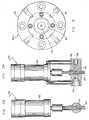
Referring now to Fig. 2, there is shown schematically asystem for co-extruding differential stiffness tubing, suchas catheters. The system includes a co-extrusion headindicated, generally, by thereference numeral 20 into which extruders 22, 24 and 26 feed the different resins, such as asoft resin and a stiff resin, that will be used to form thefinished tubing. For purposes of illustration,extruder 22provides a resinous stream for a resin "A" which, forexample, will ultimately form theoutside layer 11 of thecatheter of Fig. 1D, whileextruder 26 provides a stream ofresin "B" that will form theinterior layer 17 of thefinished catheter. Similarly,extruder 24 provides aresinous stream for resin "C" which is the material thatwill form theinside layer 13 of the finished catheter. Asillustrated in Figs. 3A and 3B, and as more fully describedhereinafter, a modulating device, indicated generally by thereference numeral 28, regulates the flow of the resins fromeach of theextruders co-extrusion head 20, while anothermodulator 27 may be used to bleed resin"A" from thehead 20 to relieve residual pressure. Toproduce catheter tubing with differential stiffness, themodulators 28 are actuated periodically and in synchronizedfashion to abruptly stop or change the resin flow to thehead 20. Because of the design ofco-extrusion head 20, theinterface between the stiff resin and soft resin isnaturally sheared and elongated when flowing through theflow channels of thehead 20. Thus, these abrupt changes orstoppages by themodulators 28 result in a very gradualchange of stiff layer thickness in the tubing, creating thegradual stiffness change and resulting in the wedgestructure in thetransition section 19 of the cathetertubing. After discharge from thehead 20, the tubing iscooled by passage through awater tank 21, alaser mike 23,puller 25 andcutter 27 to form the catheter tubing.
As is well known to those skilled in the art, aco-extrusion head is an assembly of many precision machinedparts that provide a plurality of flow channels, each ofwhich is connected to one of the extruders. Fig. 4illustrates the design of aco-extrusion head 20 forproducing a tubing of three different materials, such asthat shown in Fig. 1D. Fig. 6 illustrates a head design forproducing a tubing of two different materials, such as thetubing illustrated in Figs. 1A, 1B and 1C. Theco-extrusionhead 20 has amain body 30, usually of a cylindrical shape,in which is formed aninlet 32 for resin "A", aninlet 34for resin "B" and aninlet 36 for resin "C". Each of theinlets is connected to the respective one of theextruders mainbody 30, to a die 40 which, together with thetip 42, formsthe exit from thehead 20 for the flow of resins to createthe desired configuration of the finished product. Asillustrated in Fig. 4, theco-extrusion head 20 has aflowchannel 38 connected toinlet 32 for resin "A", aflowchannel 44 that is connected toinlet 34 for resin "B" and aflow channel 46 that is connected toinlet 36 for resin "C".Aremovable cap 48 onmain body 30 provides access to thehead to change thedie 40 andtip 42. It is not an unusualsituation that a producer of medical tubing such ascatheters will frequently change thedie 40 andtip 42without changing theentire co-extrusion head 20 in order toproduce tubing of different sizes or of different materials.This change sometimes can take place several times a day.To accommodate this need, the design of thehead 20 can be such so as to include in thesame co-extrusion head 20 bothlarge and small dies 40 andtips 42.
When used herein, a "side stream" means any resinousstream in theco-extrusion head 20 of the type of Fig. 4that is either on the outside or on the inside at point 51where the resinous streams meet prior to exiting thehead 20atpoint 52. Similarly, "interior stream" is any resinousstream in theco-extrusion head 20 that is between two sidestreams at point 51.
"Contact volume" of any resin, such as resin "C", isthe volume in the flow channel portions of theco-extrusionhead 20 where resin "C" is flowing jointly with at least oneother resin, such as resin "B", and where resin "C" is inintimate contact with solid non-moving surfaces of thehead 20 in the section where there is such joint flow. Also, theterm "contact surface" means the solid, non-moving surfaceofhead 20 with which resin "C" is in intimate contact inthe "contact volume". In Fig. 4, contact volume for resin"C", as well as resin "A", is the volume in the flow channelbetween point 51 andexit point 52. Contact volume forresin "B" is zero, since it does not contact any solidsurface after it passes point 51.
Also, by definition, the "residual flow volume of aresin" is the volume of a flow channel section between thedischarge from themodulator 28 and the point where theresin joins another resinous flow for the first time.
The "skewing volume" of a resin is the volume in a flowchannel between the point where the resin stream "C" joinsanother flow stream for the first time (the start of thecontact volume) and the point where the resin exits from theco-extrusion head 20. In the typical co-extrusion headexample of Fig. 4, the "skewing volume" of all three resinsis the volume in a flow channel between point 51 and theresin exit point 52.
As previously indicated, the contact volume and theskewing volume are probably the most influential factors informing the length of the transition section. The lower thevolumes, the shorter the transition section that will beformed. The undesirable lengthy transition section occursin prior art co-extrusion heads because the solid contactsurface drastically slows down the resin flowing by it tocause a "drag-out" effect that overly elongates the resininterface. For the shortest transition section, zerocontact volume should be designed into theco-extrusion head 20 since zero contact volume design completely orsubstantially eliminates the drag-out effect of theinterruptable resin "B", and as a result, this design willproduce the shortest transition sections possible when theflow of resin "B" is interrupted. However, as a practicalmatter, for resin "A", Fig. 4 illustrates a flow channelarrangement in a co-extrusion head design that we havetermed a "die-length contact volume" head design. With thisdesign of Fig. 4, the contact volume is no greater than thevolume covered by the length of the die 40 multiplied by afactor of 10, and is no less than the volume covered by thedie length. Preferably, the contact volume is equal to thevolume covered by the die length. This "die length contactvolume" head design is especially useful in interrupted sidestreams in co-extrusion rather than where the center streamsare interrupted, and in some designs, the use of a die is deemed necessary to control the overall tube concentricityand assure its uniformity. As a practical matter, in manycases the contact volume should not exceed the volumecontained in the desired transition section lengthmultiplied by a factor of 10. For producing some cathetersof a small diameter, the contact volume can be as small as0.5 ml. Thus, by the die-length contact volume design oftheco-extrusion head 20 as shown in Fig. 4 for resin "A",one of the most influential causes of lengthy transitionsections is practically eliminated.
Also, it is desirable to keep the discharge opening oftheflow channel 44 for resin "B" as small as possible whereit joins theflow channel 38 for resin "A". As previouslydescribed, the design of thehead 20 shown in Fig. 4 uses adie-length contact volume for resin "A", and by changing thethickness of the die 40, the contact volume can be varied.
The length of the transition section also can bechanged by a simple change of tooling in thetip 42 and die40 of thehead 20. By changing this tooling, both theskewing volume for resins "A" and "B" and the contact volumefor resin "A" can be modified.
However, there are other factors that influence thelength of thetransition section 19 in a differentialstiffness catheter. One factor that influences the lengthof the transition section is the final cross-sectional areaof the tubing to be formed. Tension and internal airpressure are applied, as is known in the art, to the hot,as-extruded tubing exiting the extrusion head, resulting inelongation and shaping of the tubing to preselected insideand outside diameters. The length of the transition section is inversely proportional to the final cross-sectional areaof the wall of the tubing. In other words, thin tubing withvery small diameters tend to have very long transitionsections.
As is well known to those skilled in the art, in anycontinuous extrusion process, when the resin flow to theextrusion head is suddenly shut off, a small amount of resinwill continue to flow for some time, even for minutes insome instances. Theoretically, this "residual flow" effecton the interrupted resin stream "B" will therefore cause alengthy transition section. However, we have determinedthat the amount of residual flow decreases with a decreasein the residual flow volume previously defined herein.Therefore, by keeping residual flow volume small, the effectof residual flow can be minimized. Another way to reducethe residual flow effect is through the use of modulators.
As is well known to those skilled in the art, after aresin stream, such as resin "B" is introduced into a streamof resin "A" as illustrated in Fig. 7, the shape of theresin stream "B" changes as it flows downwardly, and thisresults in a longer transition section. The reason for thisphenomenon is that fluids flow faster at the center of astream than at the sides, and therefore, the further thefluid flows, the more "skewed" becomes the stream. In thecase of the flow of resin "B", this results in a longertransition section. Therefore, by keeping the skewingvolume to a minimum, preferably below the resin volumecontained in the desired transition section multiplied by afactor of 10, the length of the transition section can alsobe kept to a minimum.
The length of the transition section can also bechanged by changing the viscosity of the resins. Forexample, when the leading edge of the stiff layer is used towedge into the layer of softer material as illustrated inFigs. 1A, 1B, 1C, 1D and 1E, raising the viscosity of thestiff layer or lowering the viscosity of the softer sidelayers will shorten the length of the transition section.
Note that from the design of the flow channels in thehead 20 as illustrated in Figs. 4 and 6, all of theforegoing factors have been designed into thehead 20 so asto result in keeping thetransition section 19 to a desiredshort length. Another important feature of thehead 20 ofthe invention is the use of means to adjust the "slanting"of the "wedge" of the stiff layer. In Figs. 4 and 6 thehead design includes adjustment screws 54 on the rear of thehead 20. By adjusting the screws 54, the length of theannular stiff layer, and thus the length of thetransitionsection 19, can be varied along only a portion of theannular layer to produce a slanted end, as illustrated inFig. 8A. Fig. 8B shows the stiff layer of uniform lengtharound the entire circumference to produce an "even" wedge.In Figs. 8A and 8B, the tubings are shown schematically; inparticular, the downstream, thinner ends of the wedges ofthe stiff layers are shown as sharp edged and smooth. Inthe actual product produced by the process described above,however, the downstream edge of the wedged-in layer ends ina plurality of longitudinally extending "spear points" ofone material extending into the other in the wall of thetransition section, as shown in Fig. 8C. (In the tubing ofFigs. 8A - 8C, points of the stiffer material extend into the softer material.) The downstream ends of the points arecircumferentially spaced apart in the wall of the transitionsection, and the points gradually increase in size in theupstream direction until they join to form the annular layershown in Figs. 8A - 8C.
Also, as is evident to those skilled in the art that inmaking tubing for catheter applications, it is veryimportant to have precise control over the inside andoutside diameters of the tubing as well as the wallthicknesses. In any tube extrusion process, some variationin tube diameter (either interior or outside diameter)always occurs if the total resin flow rate is changed. Thevariations in diameter also occur when total resin flow isreduced due to the interruption of one or more resin streamsin co-extrusion processes. The extent of the diameterchange increases with the increased percentage of the streamof the interruptable resin relative to the total resin flow.Therefore, too sudden an interruption, although good forproducing short transition sections, can sometimes producetoo sudden a change in the diameter of the tubing and resultin undesirable ripples. Also, because there is always a lagbetween interruption induced diameter change and thetransition section of a tube, this lag distance can be asshort as a fraction of an inch or as long as many feet. Thelag distance increases with the increase of skewing volumeand it is inversely proportional to the finalcross-sectional area of the tubing.
An important design feature of the invention is thattheco-extrusion head 20 of the invention has no movingparts, thus assuring that the diameter of the tubing will be consistently accurate which is especially important formedical tubing such as catheters. Also important inmaintaining consistent diameters of the tubing is the closematch of melt strengths of the resins used.
Although most of the emphasis in the system of theinvention has been on the design of theco-extrusion head 20in order to produce tubing of a consistent diameter andhaving a transition section of a desired short length, themodulator 28 is also important in order to regulate andcontrol the actual length of the transition section as wellas the profile for any particular tubing. The modulator 28functions to regulate the flow rate of the resins in a rapidand precise fashion. Atypical modulator 28 is illustratedin Figs. 3A and 3B, which show a two-stage type modulator inwhich the flow can be regulated so as to flow through to thehead 20 or interrupted to direct the resin flow to arecycling container (not shown). Themodulator 28 must befast acting so as to operate to change the flow within nomore than two seconds and preferably in less than 0.5seconds. Themodulator 28 thus has aninlet 56 leading to achamber 57 into which extends avalve member 58 operated byactuator 60. Depending upon the position ofvalve member 58, the resin flowing into thechamber 57 is directed to theoutlet 62 which is connected to thehead 20 or the resin isdirected into abypass outlet 64. A variety of differentdesigns of the modulatingdevice 28 can be utilized as longas they have extremely fast responses and can produce ratherprecise flow controls. Since a typical cycle for making onelength of tubing for a single catheter is only about 0.5 to10 seconds, rapid response is extremely necessary. If desired, themodulator 28 can be replaced by a plunger typemodulating device, actuated by a servo valve with aprogrammer (not shown). The programmer may be of anysuitable design such as that marketed by "Moog" Electronicsand Systems Division which produces and markets a line ofparison programming systems.
It should be noted that if theco-extrusion head 20 isproperly designed and operated, rather simple on-off typesof modulating devices may be sufficient, depending upon thetype of tubing being produced. Also, devices withmechanical gradual flow reduction or gradual flow-increasefunctions can also be used depending upon the tubingrequirements.
Although modulators may be programmed to deliver tubinghaving a consistent diameter throughout the productioncycle, small variations do occur due to slight mismatches ofthe modulators. A tubing can be produced with the mostconsistent diameter, e.g., for use as a catheter (beforetapering) by keeping the skewing volume greater than theresin volume contained indistal section 16 of the catheter,and preferably greater than the resin volume of the distalsection multiplied by a factor of 5.
In Fig. 7 there is illustrated the operating steps of acomplete cycle for producing the differential stiffnesscatheter of Fig. 1D. This figure shows schematically thedie 40 andtip 42 of thehead 20 and illustrates the flow ofthe resins through thedie 40 andtip 42. In the firstphase, the flow of resin "B" is stopped while the flow ofresins "A" and "C" are on. This forms the softdistalsection 16 from resin "A" with a thininside layer 13 formed of the material of resin "C". The flow of resin "B" is thencommenced while the rate of flow of resin "A" is reduced andthe flow of resin "C" continues. In this phase, thetransition section 19 is formed. In the third phase, theflow of all three resins is on to form the stiff,multi-layeredproximal section 18. In the last phase, theflow of resin "B" is stopped and the rate of flow of resin"A" is increased to purge out resin "B". The cycle is thenrepeated starting with the first phase. Note that in allphases the flow of resin "C" is continuous and at a constantrate. This illustration of a complete cycle of a processperformed according to the principles of the invention showsthat the process extrudes different resins sequentially aswell as simultaneously. Prior art processes teach onlysimple co-extrusion in which different resins are extrudedsimultaneously only.
Although in many cases of differential stiffness tubingonly one stiff resin will follow one soft resin in aconsecutive manner, there are applications in which three orfour resins of different stiffness are co-extrudedconsecutively to produce a finished product with improvedkink-resistance, and with such a process, better control oftubing diameters can be achieved.
The head and systems designs of the invention are alsouseful where it is desired to obtain a specified diameterand wall thickness and to combine interrupted resin streamstechnology with tapering and lumen air regulatingtechniques. When so doing, the timing of all these devicesshould be synchronized to avoid drift.
It is also known to those skilled in the art that inco-extruded products, a side layer of non-sticking,non-compatible material can be removed in a post-extrusionoperation resulting in a product with one less layer. Whenthis technique is used on tubing made with the methods andsystems described herein, this technique can be beneficialin reducing diameter fluctuations due to resin melt strengthdifferences as well as other reasons.
There are some applications where it is desirable toincrease the transition section in a medical tube, such as acatheter. The obvious remedy is to use the modulatingdevice 28 to lengthen the transition section. However, aspreviously described, it is also possible to increase thecontact volume and/or the skewing volume in order tolengthen this transition section.
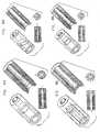
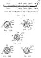
From the foregoing description it will be evident thatwe have described a new technology for making tubing,especially medical tubing for such applications as variablestiffness catheters, soft tip catheters, etc. However,multi-lumen catheters can also be made using the principlesof the invention. A typical multi-lumen tubing for such acatheter is shown in Figs. 12A - 12F. In Fig. 12A,tubing 100 includes stifferproximal section 101,transitionsection 102, and softerdistal section 103. Fig. 12Billustrates a cross section of softerdistal section 103taken along line B-B of Fig. 12A. In Fig. 12B,distalsection 103 includeslumens 104 formed withinsoftermaterial 105. Figs. 12C - 12E illustrate cross sections oftransition section 102 taken along line C-C, D-D, and E-E,respectively, of Fig. 12A. In Fig. 12C, the portion oftransition section 102 neardistal section 103 includeslumens 104 formed withinsofter material 105, with insertsofstiffer material 106 on either side oflumens 104. Fig.12D, from near the center oftransition section 102, issimilar to Fig. 12C, but with larger insertions ofstiffermaterial 106. In Fig. 12E, the portion oftransitionsection 102 nearproximal section 101 is made up largely ofstiffer material 106, with thin layers ofsofter material 105adjacent lumens 104 and the outer surface oftransitionsection 103. In Fig. 12F,proximal section 101 includesonlystiffer material 106, withlumens 104 formedtherewithin. Typically, when a plurality of stiffersections (each of which may form one or two proximalsections 101) and softer sections (each of which may formone or two distal sections 103) are extruded, a smallremnant of stiffer material remains at the core of thesofter and transition sections between stiffer sections.Such a remnant is shown in Figures 12B, 12C, and 12D asremnant 107 ofstiffer material 106.
Alternatively, the multi-lumen catheter may includethree or more lumens, and the lumens may have any of avariety of shapes and may be of the same or different shapesand sizes. Such multi-lumen tubing is useful forapplications in which known multi-lumen tubing has beenfound useful, for example, in balloon catheters orelectrophysiology (EP) catheters. A particular advantage isprovided by the variable stiffness tubing in an EP catheter.When the distal tip of the EP catheter is deflected formaneuvering of the catheter through tortuous anatomies, theshort transition section and soft distal section permit faster recovery of the straight-line axial configurationthan has been achieved in prior art EP catheters.
Also, in addition to the two and three resin systemsdescribed herein, more than three resin systems can be made,such as for channel balloon concepts and for somemulti-lumen concepts. It should also be pointed out thatthe differential stiffness tubing made according to theinvention not only can be used for making the full length ofthe catheter, they can also be used to make only a part ofthe catheter. For example, the invention can be used tomake a single lumen tubing inside the balloon, or produce acatheter with the distal section combined with a proximalsection formed of either a braided construction or a metaltubing such as Nitenol tubing. Another type of catheterconstruction to which the principles of the invention can beapplied is to produce a catheter with a low friction layeron the inside surface for good guidewire movement.
In yet another type of catheter construction, thecatheter distal section may be shaped, e.g., by heating toform a bent configuration in its relaxed state. Forexample, a J-tip or hook-shaped profile may be formed at thedistal tip of the catheter. The wall of this bent or othercatheter may be perforated by known means, e.g., at theproximal section to provide for inflation of a balloon viathe central passageway or at the transition or distalsection to provide for dispensing of fluid medication or afluoroscopic dye. An example of such a catheter is shown inFig. 13, showingangiographic catheter 110 having proximalsection 111,transition section 112, anddistal section 113.Distal section 113 has been, e.g., heated and bent to formloop 114 in its relaxed configuration. In use,catheter 110is threaded onto a guidewire (not shown), which holdsdistalsection 113 in a configuration generally coaxial with theguidewire. When thedistal section 113 is in positionwithin a bodily passage, the guidewire may be partiallywithdrawn to permitdistal section 113 to formloop 114 ofits relaxed configuration, which holdscatheter 110 inplace. The wall oftransition section 112 may be perforatedto provideapertures 115 for fluid communication betweencentral passageway 116 ofcatheter 110 and the outside ofthe catheter.Apertures 115 may be used for, e.g., thedispensing of a dye for fluoroscopic viewing of the bodilypassage.
In addition to differential stiffness catheters, theinvention can be employed to produce soft-tip catheters,catheters of varied colors and for "strain-relief" of anypart of a catheter. In the last mentioned case, a shortdifferential stiffness section of the catheter is formed atthe proximal end to provide a transition from the connector,for example, to which the tubing is attached and the mainportion of the proximal end of the catheter. Alternatively,a separate short piece of differential stiffness tubing canbe used to provide improved strain relief to a knowntubing/connector assembly. A strain relief insert of thistype is shown in Fig. 14.Catheter 120 of Fig. 14 includesflexible shaft 121 andrigid fitting 122 coaxial withshaft 121,shaft 121 extending proximally and distally fromfitting 122. Tubularstrain relief insert 123, which is alength of differential stiffness tubing, jacketsflexibleshaft 121 in the area of joint 124 betweenshaft 121 andfitting 122.Portion 125 of stiffsecond section 126 ofstrain relief insert 123 is disposed betweenshaft 121 andfitting 122, while the remainder ofsecond section 126,transition section 127, and softfirst section 128 ofinsert 123 extend distally aboutshaft 121, providing graduatedflexibility to joint 124 to prevent kinking of the joint.
A typical soft tip guiding catheter is shown in Fig.15, in which softtip guiding catheter 130 includesproximalsection 131,transition section 132, anddistal section 133.Transition section 132 has been, e.g., heat treated to formS-shapedportion 134 for maneuverability of the catheter,while shortdistal section 133 provides low-trauma soft tip135 for the catheter. Typically, stifferproximal section 131 has been reinforced with a metal braid jacket (notshown) embedded in the wall ofproximal section 131. Suchan embedded metal braid jacket is described further below.
The invention, however, is not limited to catheterproducts but can also be employed in producing other typesof tubing and rods that require sections of variedproperties. For example, Fig. 10 illustrates "bump" tubingin which the insert end is of stiffer material and the bellend is of soft material. Unlike bump tubing produced usingprior art methods where both ends are soft, the stiff insertend of the tubing produced by the invention provides for amore secure and tighter fitting connection. Also, theinvention can be used to produce a new tubing for quickconnect fittings in which the ends are of stiff material butalternating sections are of a softer material to provideflexibility for the length of tubing between the fittingswhile the stiff ends are easier to fit into quick connect fittings. A tubing of this type is shown in Fig. 11. Thetube includes several stiff first sections, each pair offirst sections having a soft second section therebetween.Each stiff section is joined to an adjacent soft section bya transition section to form a continuous unbroken tube ofdifferential stiffness without abrupt joints.Alternatively, only the ends of the tubing may be formed ofstiff first sections, while a single long soft section mayextend therebetween. The tubing of Fig. 11 may be providedin a long length for cutting at the center of any of itsstiffer sections to provide a shorter length of soft,flexible tubing with stiff ends suitable for inserting intoquick connect fittings.
Fig. 16 shows another product of the invention,coatedguidewire 140 for use with a medical catheter.Coatedguidewire 140 includesguidewire 141 jacketed withdifferential stiffness tubing 142 along part or all of itslength, stifferproximal section 143,transition section 144, and softerdistal section 145 oftubing 142 providingdifferential stiffness tocoated guidewire 140.Wire 141may be a single filament wire. Typically, guidewire 141 hasproximal end 146 of uniform stiffness throughout its lengthanddistal end 147 tapered to decrease its stiffness in thedistal direction. As shown in Fig. 16,jacket 142 may beapplied with increasing thickness in the distal direction tolessen the diameter difference between the wireproximal end 146 and wiredistal end 145, and preferably to provide auniform or near-uniform outer diameter along the length ofguidewire 140. The differential stiffness tubing described herein also may be utilized to jacket a cable to providedifferential stiffness to the cable.
In most of these applications for the invention, themain consideration in the method and systems describedherein as well as the specific designs of the co-extrusionheads is the ability to make short and controlled transitionsections in co-extruded tubing which have interrupted layersor elements. This technique is thus named "SCTS"technology. We have described in detail how this can beaccomplished and we have also indicated the many and variedapplications for a variety of different types of tubing thatone may wish to produce.
The principles of the invention can be used to processa number of different materials used in making tubing. Forexample, nylons (polyamides), HDPE'S, polyesters,polypropylenes and other materials, including mineral andfiber-filled materials, can be used for the stiff layer orsection of a tubing. For the soft layer or section, suchmaterials as ethylene vinyl acetate, ethylenic copolymers,polyamide elastomers, polyurethanes and other thermoplasticelastomers can be used. If the tubing is for a medicalcatheter requiring a guidewire, many of the above listedmaterials for the stiff layer can be used for the insidelayer that will come into contact with the guidewire,especially if the material is combined with currentorientation technology to provide a low-friction surface.Also, all resins can be filled with radio opacity or notdepending upon the intended use of the finished product.Moreover, in some applications for a finished product madeusing the invention principles, good adhesion between layers is necessary while in other applications that is not arequirement. In either case, the invention can be used.
Another advantage of the invention is the versatilitythat it provides. Because the principles of the inventioncan be used to produce tubing in a continuous reel, theprinciples can be combined with other technologies toenhance the properties of the finished product. Forexample, tapering combined with lumen air control has beensuccessfully employed to vary I.D., O.D. or wall thicknessin some sections of a catheter. In particular, theinvention can be used to produce microcatheters with adesired tip section having a thinner wall and smaller O.D.but with only a very slightly smaller I.D. Braiding ofmetal and non-metal wires can also be used with productsproduced by the invention to give the finished product moretorqueability, higher stiffness, etc., and wire winding canbe added to give additional kink resistance. Such tubingsare illustrated in Figs. 17 and 18, respectively. Fig. 17,not drawn to scale, shows metal braid reinforcedtubing 150made up ofdifferential stiffness tubing 151 and metal meshor braid 152 to provide a reinforcing sleeve overtubing 151. In Fig. 17,braid 152 is shown as forming a sleeveover onlyproximal section 153 of the tubing.Alternatively, braid 152 may extend distally fromproximalsection 153 to provide reinforcement totransition section 154 and, if desired, part or all ofdistal section 155. InFig. 18, not drawn to scale, similar features to those shownin Fig. 17 are indicated by the same reference numerals.Fig. 18 shows wire woundtubing 156 made up ofdifferentialstiffness tubing 151 andmetal wire 157 wound aroundtubing 151 to provide reinforcement. In Fig. 18,wire 157 is shownas being wound over onlyproximal section 153 of the tubing.Alternatively,wire 157 may extend distally fromproximalsection 153 to provide reinforcement totransition section 154 and, if desired, part or all ofdistal section 155.Either reinforcedtubing braid 152 orwire 157 in the outer surfaceof the tube wall, as shown for reinforcedtubing 150.
In addition, irradiation and orientation technologiescan be employed along with the invention to produce tubingof higher strength, more dimensional stability, lowerelongation, etc. The latter is beneficial to prevent neck-downof catheters that results in clamping of the catheteronto the guidewire when subjected to axial stress during amedical procedure. Plastic foam technologies can also beemployed with the method of the invention to produce super-softtips.
From the foregoing description it is obvious that thenumber of layers, the type of layer and material used forthe tubing, etc. will vary depending upon the particularcharacteristics desired, but it should be understood thatcatheters or tubes having multiple layers of a variety ofmaterials and arranged differently than the illustratedembodiments can be formed using the principles of theinvention. It is our intention however, that all such revisions and modifications that are obviousto those skilled in the art will be included within thescope of the following claims:
Claims (17)
- A medical device comprising an elongated tubehaving a proximal section and a distal section, said tubehaving an annular wall with an outer surface and an innersurface that defines a central passageway that extendssubstantially the length of the tube, said tube beingconstructed of a first material and a second materialhaving less stiffness than the first material, the wallof the tube gradually changing from the first material tothe second material to form a transition section betweenthe proximal section and the distal section, the firstand second materials being gradually combined in thetransition section and naturally adhering to each otherto form a wall gradually changing from one substantiallymade up of the first material to one substantially madeup of the second material to form a continuous unbrokentube of materials having different properties and withoutabrupt joints, the distal section being made of thesecond material and therefore less stiff than theproximal section.
- The medical device of claim 1, in which theaverage length of the transition section is about 0.25-20inches.
- The medical device of claim 1, in which theproximal section is substantially longer than thecombined length of the transition section and the distalsection, and the transition section is formed into agenerally S-shaped configuration.
- The medical device of claim 1, in which theannular wall defines at least one additional passagewayextending substantially the entire length of the tube,and a balloon is located at the end of the distal section of the tube, said balloon adapted to be inflated by fluidpassed through one of the passageways.
- The medical device of claim 2, in which theaverage length of the transition section is about 0.25-20inches.
- The medical device of claim 5, furthercomprising a circumferential layer of braided meshmaterial embedded in said wall along at least a portionof the wall.
- The medical device of claim 5, furthercomprising a helically wound metal coil embedded in saidwall in at least a portion of the tube.
- The medical device of claim 2, in which thetransition section is curved in its relaxed state and thedistal section is sufficiently soft to provide a low-traumaend at the end of the distal section for guidingthe device when used as a catheter.
- The medical device of claim 8, in which thetransition section is provided with openings to providefor discharge of fluid passed through the passageway.
- A medical device having an annular wall with anouter surface and an inner surface which inner surfacedefines a central passageway of a uniform size, said tubecomprising a first section comprised primarily of a firstmaterial that forms the inner surface of the wall, asecond section comprised primarily of a second materialthat forms the outer surface of the wall, the first andsecond materials being of different stiffness, and anintermediate section joining the first section and thesecond section, the intermediate section being atransition section in which the wall of the tubegradually changes from the primary material of the firstsection to the primary material of the second section to form a continuous unbroken tube of differential stiffnesswithout abrupt joints, the materials of the first sectionand the second section naturally adhering to each otherand being gradually combined in the transition section toform a structure in which the first material continues toform the inner surface of the wall of the tube within thetransition section and the second material continues toform the outer surface of the wall of the tube within thetransition section, the second material being less stiffthan the first material.
- The medical device of claim 10, in which theaverage length of the transition section is about 0.25-20inches.
- The medical device of claim 11, in which thefirst section is substantially longer than the combinedlength of the transition section and the second section,and the transition section is formed into a generally S-shapedconfiguration.
- The medical device of claim 10, in which theannular wall defines at least one additional passagewayextending substantially the entire length of the tube,and a balloon is located at the end of the secondsection of the tube, said balloon adapted to be inflatedby fluid passed through one of the passageways.
- The medical device of claim 11, furthercomprising a circumferential layer of braided meshmaterial embedded in said wall along at least a portionof the wall.
- The medical device of claim 11, furthercomprising a helically wound metal coil embedded in saidwall in at least a portion of the tube.
- The medical device of claim 11, in which thetransition section is curved in its relaxed state and the distal section is sufficiently soft to provide a low-traumaend at the end of the distal section for guidingthe device when used as a catheter.
- The medical device of claim 11, in which thetransition section is provided with openings to providefor discharge of fluid passed through the passageway.
Applications Claiming Priority (3)
| Application Number | Priority Date | Filing Date | Title |
|---|---|---|---|
| US230333 | 1994-04-20 | ||
| US08/230,333US5533985A (en) | 1994-04-20 | 1994-04-20 | Tubing |
| EP95915023AEP0756504B1 (en) | 1994-04-20 | 1995-04-03 | Medicat tubing |
Related Parent Applications (1)
| Application Number | Title | Priority Date | Filing Date |
|---|---|---|---|
| EP95915023ADivisionEP0756504B1 (en) | 1994-04-20 | 1995-04-03 | Medicat tubing |
Publications (2)
| Publication Number | Publication Date |
|---|---|
| EP0987044A2true EP0987044A2 (en) | 2000-03-22 |
| EP0987044A3 EP0987044A3 (en) | 2002-10-30 |
Family
ID=22864819
Family Applications (3)
| Application Number | Title | Priority Date | Filing Date |
|---|---|---|---|
| EP95915023AExpired - LifetimeEP0756504B1 (en) | 1994-04-20 | 1995-04-03 | Medicat tubing |
| EP99122701ACeasedEP0987043A3 (en) | 1994-04-20 | 1995-04-03 | Tubing and method for making same |
| EP99122708AWithdrawnEP0987044A3 (en) | 1994-04-20 | 1995-04-03 | Tubing and method for making same |
Family Applications Before (2)
| Application Number | Title | Priority Date | Filing Date |
|---|---|---|---|
| EP95915023AExpired - LifetimeEP0756504B1 (en) | 1994-04-20 | 1995-04-03 | Medicat tubing |
| EP99122701ACeasedEP0987043A3 (en) | 1994-04-20 | 1995-04-03 | Tubing and method for making same |
Country Status (6)
| Country | Link |
|---|---|
| US (3) | US5533985A (en) |
| EP (3) | EP0756504B1 (en) |
| JP (1) | JPH09512445A (en) |
| CA (1) | CA2188013C (en) |
| DE (1) | DE69517317T2 (en) |
| WO (1) | WO1995028982A1 (en) |
Cited By (1)
| Publication number | Priority date | Publication date | Assignee | Title |
|---|---|---|---|---|
| EP1658951A4 (en)* | 2003-08-27 | 2009-04-22 | Pla Giken Co Ltd | Extrusion molding apparatus for resin tube |
Families Citing this family (309)
| Publication number | Priority date | Publication date | Assignee | Title |
|---|---|---|---|---|
| NL9301642A (en)* | 1993-09-22 | 1995-04-18 | Cordis Europ | Microcatheter. |
| US6659977B2 (en)* | 1993-10-27 | 2003-12-09 | Schneider (Europe) A.G. | Multilayer interventional catheter |
| US5961765A (en)* | 1994-09-20 | 1999-10-05 | Schneider (Europe) A. G. | Method of making a catheter |
| DE69326551T2 (en)* | 1993-10-27 | 2000-03-02 | Schneider (Europe) Gmbh, Buelach | Interventional catheter |
| US5533985A (en)* | 1994-04-20 | 1996-07-09 | Wang; James C. | Tubing |
| EP0729766A1 (en)* | 1995-03-03 | 1996-09-04 | Cordis Europa N.V. | Microcatheter |
| AU7386996A (en)* | 1995-10-17 | 1997-05-07 | Medtronic, Inc. | Guide catheter with soft distal segment |
| US5733496A (en)* | 1995-10-27 | 1998-03-31 | Cordis Corp. | Electron beam irradiation of catheters to enhance stiffness |
| US20030069522A1 (en) | 1995-12-07 | 2003-04-10 | Jacobsen Stephen J. | Slotted medical device |
| US5836893A (en)* | 1996-03-08 | 1998-11-17 | Scimed Life Systems, Inc. | Intravascular guidewire |
| US5800410A (en)* | 1996-04-19 | 1998-09-01 | Becton Dickinson And Company | Catheter with stress distribution fingers |
| ATE327797T1 (en)* | 1996-04-26 | 2006-06-15 | Schneider Europ Gmbh | INTERVENTION CATHETER |
| US6488637B1 (en)* | 1996-04-30 | 2002-12-03 | Target Therapeutics, Inc. | Composite endovascular guidewire |
| US5851464A (en)* | 1996-05-13 | 1998-12-22 | Cordis Corporation | Method of making a fuseless soft tip catheter |
| US6017319A (en)* | 1996-05-24 | 2000-01-25 | Precision Vascular Systems, Inc. | Hybrid tubular guide wire for catheters |
| US6440088B1 (en)* | 1996-05-24 | 2002-08-27 | Precision Vascular Systems, Inc. | Hybrid catheter guide wire apparatus and method |
| US6524299B1 (en)* | 1997-04-09 | 2003-02-25 | Target Therapeutics, Inc. | Flow-directed catheter |
| US6165166A (en)* | 1997-04-25 | 2000-12-26 | Schneider (Usa) Inc. | Trilayer, extruded medical tubing and medical devices incorporating such tubing |
| CA2287846A1 (en)* | 1997-05-05 | 1998-11-12 | Micro Therapeutics, Inc. | Single segment microcatheter |
| US5976120A (en)* | 1997-05-05 | 1999-11-02 | Micro Therapeutics, Inc. | Single segment microcatheter |
| US5938653A (en) | 1997-06-09 | 1999-08-17 | Scimed Life Systems, Inc. | Catheter having controlled flexibility and method of manufacture |
| AU7953698A (en) | 1997-06-13 | 1998-12-30 | Micro Therapeutics, Inc. | Contoured syringe and novel luer hub and methods for embolizing blood ve ssels |
| US6030369A (en)* | 1997-07-03 | 2000-02-29 | Target Therapeutics Inc. | Micro catheter shaft |
| US6217566B1 (en)* | 1997-10-02 | 2001-04-17 | Target Therapeutics, Inc. | Peripheral vascular delivery catheter |
| US6077258A (en)* | 1997-10-03 | 2000-06-20 | Scimed Life Systems, Inc. | Braided angiography catheter having full length radiopacity and controlled flexibility |
| US5908413A (en)* | 1997-10-03 | 1999-06-01 | Scimed Life Systems, Inc. | Radiopaque catheter and method of manufacture thereof |
| US6132388A (en)* | 1997-10-16 | 2000-10-17 | Scimed Life Systems, Inc. | Guide wire tip |
| US6093157A (en)* | 1997-10-22 | 2000-07-25 | Scimed Life Systems, Inc. | Radiopaque guide wire |
| US6007478A (en)* | 1997-11-13 | 1999-12-28 | Impella Cardiotechnik Aktiengesellschaft | Cannula having constant wall thickness with increasing distal flexibility and method of making |
| US6036682A (en) | 1997-12-02 | 2000-03-14 | Scimed Life Systems, Inc. | Catheter having a plurality of integral radiopaque bands |
| JP2003521261A (en) | 1997-12-22 | 2003-07-15 | マイクルス コーポレイション | Variable rigidity optical fiber shaft |
| JP4612186B2 (en) | 1998-02-24 | 2011-01-12 | ナビリスト メディカル, インコーポレイテッド | High flow dialysis catheter and related methods |
| US6340441B1 (en) | 1998-03-13 | 2002-01-22 | Scimed Life Systems, Inc. | Multi-layer guide wire and method of manufacture therefor |
| GB2336338A (en)* | 1998-04-15 | 1999-10-20 | Smiths Industries Plc | Manufacture of a catheter by co-extrusion |
| US6171296B1 (en) | 1998-04-28 | 2001-01-09 | Microtherapeutics, Inc. | Flow directed catheter |
| US6106510A (en)* | 1998-05-28 | 2000-08-22 | Medtronic, Inc. | Extruded guide catheter shaft with bump extrusion soft distal segment |
| US7815626B1 (en) | 1998-06-12 | 2010-10-19 | Target Therapeutics, Inc. | Catheter with knit section |
| US6126650A (en)* | 1998-06-30 | 2000-10-03 | Cordis Corporation | Flow directed catheter having radiopaque strain relief segment |
| US6165165A (en)* | 1998-10-02 | 2000-12-26 | Genx International, Inc. | Embryo-implanting catheter assembly and method for making the same |
| JP3637216B2 (en)* | 1998-10-09 | 2005-04-13 | ペンタックス株式会社 | Endoscopic treatment tool |
| US20020007145A1 (en)* | 1998-10-23 | 2002-01-17 | Timothy Stivland | Catheter having improved bonding region |
| US6165140A (en) | 1998-12-28 | 2000-12-26 | Micrus Corporation | Composite guidewire |
| US6171295B1 (en) | 1999-01-20 | 2001-01-09 | Scimed Life Systems, Inc. | Intravascular catheter with composite reinforcement |
| US6942654B1 (en) | 2000-01-19 | 2005-09-13 | Scimed Life Systems, Inc. | Intravascular catheter with axial member |
| US6709429B1 (en)* | 2000-01-19 | 2004-03-23 | Scimed Life Systems, Inc. | Intravascular catheter with multiple axial fibers |
| US6374476B1 (en)* | 1999-03-03 | 2002-04-23 | Codris Webster, Inc. | Method for making a catheter tip section |
| US6400992B1 (en) | 1999-03-18 | 2002-06-04 | Medtronic, Inc. | Co-extruded, multi-lumen medical lead |
| US6887235B2 (en) | 1999-03-24 | 2005-05-03 | Micrus Corporation | Variable stiffness heating catheter |
| US6352531B1 (en) | 1999-03-24 | 2002-03-05 | Micrus Corporation | Variable stiffness optical fiber shaft |
| US6270082B1 (en)* | 1999-09-14 | 2001-08-07 | Dana Corporation | Coextruded valve stem seal |
| JP2003512946A (en)* | 1999-10-29 | 2003-04-08 | ボストン サイエンティフィック リミテッド | Method and apparatus for extruding catheter tubing |
| US6354331B1 (en) | 1999-11-08 | 2002-03-12 | Parker-Hannifin Corp. | Flexible plastic tubing construction having a sight glass window |
| US6579484B1 (en)* | 1999-12-16 | 2003-06-17 | Advanced Cardiovascular Systems, Inc. | Co-extruded taper shaft |
| DE60128663T2 (en) | 2000-03-23 | 2008-01-31 | Cook Inc., Bloomington | CATHETER INTRODUCTION SLEEVE |
| US6860849B2 (en)* | 2000-05-08 | 2005-03-01 | Pentax Corporation | Flexible tube for an endoscope |
| US6881209B2 (en)* | 2000-05-25 | 2005-04-19 | Cook Incorporated | Medical device including unitary, continuous portion of varying durometer |
| US20050003034A1 (en)* | 2000-05-26 | 2005-01-06 | Gma Co., Ltd. | Stiffness-taper tubing and the manufacturing method, and manufacturing apparatus for such tubing |
| JP3386802B2 (en) | 2000-05-26 | 2003-03-17 | ジーマ株式会社 | Hardness taper tube, method of manufacturing the same, and manufacturing apparatus |
| DE10035497A1 (en)* | 2000-07-19 | 2002-01-31 | Enbw Ag | Method and electrode for the electrokinetic remediation of contaminated soil containing pore fluid |
| US6663614B1 (en) | 2000-11-06 | 2003-12-16 | Advanced Cardiovascular Systems, Inc. | Catheter shaft having variable thickness layers and method of making |
| US6629952B1 (en) | 2000-12-29 | 2003-10-07 | Scimed Life Systems, Inc. | High pressure vascular balloon catheter |
| DE10105592A1 (en) | 2001-02-06 | 2002-08-08 | Achim Goepferich | Placeholder for drug release in the frontal sinus |
| US20040065979A1 (en)* | 2001-02-26 | 2004-04-08 | Wang James C. | Injector tip-and-die assembly construction and method |
| US6444915B1 (en) | 2001-02-26 | 2002-09-03 | James C. Wang | Foldable electric cord arrangement and manufacture |
| US6648024B2 (en)* | 2001-02-26 | 2003-11-18 | James C. Wang | Tubular product |
| ITMI20010404A1 (en)* | 2001-02-28 | 2002-08-28 | Gimac Di Maccagnan Giorgio | EXTRUSION HEAD AS WELL AS EXTRUSION EQUIPMENT EQUIPPED WITH SUCH HEAD |
| US6719804B2 (en) | 2001-04-02 | 2004-04-13 | Scimed Life Systems, Inc. | Medical stent and related methods |
| US7674245B2 (en)* | 2001-06-07 | 2010-03-09 | Cardiac Pacemakers, Inc. | Method and apparatus for an adjustable shape guide catheter |
| DE20110121U1 (en)* | 2001-06-19 | 2002-12-05 | B. Braun Melsungen Ag, 34212 Melsungen | catheter |
| US20030009151A1 (en)* | 2001-07-03 | 2003-01-09 | Scimed Life Systems, Inc. | Biaxially oriented multilayer polymer tube for medical devices |
| US6761703B2 (en)* | 2001-07-03 | 2004-07-13 | Scimed Life Systems, Inc. | Catheter incorporating a high column high column strength distal tip region |
| US6776945B2 (en) | 2001-07-03 | 2004-08-17 | Scimed Life Systems, Inc. | Medical device with extruded member having helical orientation |
| US20030009208A1 (en) | 2001-07-05 | 2003-01-09 | Precision Vascular Systems, Inc. | Torqueable soft tip medical device and method of usage |
| GB0120645D0 (en) | 2001-08-24 | 2001-10-17 | Smiths Group Plc | Medico-surgical devices |
| US6863678B2 (en) | 2001-09-19 | 2005-03-08 | Advanced Cardiovascular Systems, Inc. | Catheter with a multilayered shaft section having a polyimide layer |
| US6620202B2 (en) | 2001-10-16 | 2003-09-16 | Scimed Life Systems, Inc. | Medical stent with variable coil and related methods |
| US20040143180A1 (en)* | 2001-11-27 | 2004-07-22 | Sheng-Ping Zhong | Medical devices visible under magnetic resonance imaging |
| US6755812B2 (en)* | 2001-12-11 | 2004-06-29 | Cardiac Pacemakers, Inc. | Deflectable telescoping guide catheter |
| US7914486B2 (en)* | 2001-12-20 | 2011-03-29 | Boston Scientific Scimed, Inc. | Catheter having an improved balloon-to-catheter bond |
| US6923787B2 (en)* | 2001-12-20 | 2005-08-02 | Scimed Life Systems, Inc. | Catheter having an improved balloon-to-catheter bond |
| US7717899B2 (en) | 2002-01-28 | 2010-05-18 | Cardiac Pacemakers, Inc. | Inner and outer telescoping catheter delivery system |
| US20030145122A1 (en)* | 2002-01-30 | 2003-07-31 | International Business Machines Corporation | Apparatus and method of allowing multiple partitions of a partitioned computer system to use a single network adapter |
| US7985234B2 (en)* | 2002-02-27 | 2011-07-26 | Boston Scientific Scimed, Inc. | Medical device |
| US20030165647A1 (en)* | 2002-03-04 | 2003-09-04 | Terumo Kabushiki Kaisha | Medical tubing and extrusion die for producing the same |
| US9694166B2 (en) | 2002-03-26 | 2017-07-04 | Medtronics Ps Medical, Inc. | Method of draining cerebrospinal fluid |
| US6979420B2 (en) | 2002-03-28 | 2005-12-27 | Scimed Life Systems, Inc. | Method of molding balloon catheters employing microwave energy |
| CA2477758A1 (en)* | 2002-03-28 | 2003-10-09 | Scimed Life Systems, Inc. | Polymer welding using ferromagnetic particles |
| US7163655B2 (en)* | 2002-03-28 | 2007-01-16 | Scimed Life Systems, Inc. | Method and apparatus for extruding polymers employing microwave energy |
| US7914467B2 (en)* | 2002-07-25 | 2011-03-29 | Boston Scientific Scimed, Inc. | Tubular member having tapered transition for use in a medical device |
| DE60334122D1 (en)* | 2002-07-25 | 2010-10-21 | Boston Scient Ltd | MEDICAL DEVICE FOR NAVIGATING THROUGH ANATOMY |
| US7163531B2 (en)* | 2002-08-19 | 2007-01-16 | Baxter International, Inc. | User-friendly catheter connection adapters for optimized connection to multiple lumen catheters |
| US20040034333A1 (en)* | 2002-08-19 | 2004-02-19 | Seese Timothy M. | Dialysis catheters with optimized user-friendly connections |
| US20040039371A1 (en)* | 2002-08-23 | 2004-02-26 | Bruce Tockman | Coronary vein navigator |
| US8317816B2 (en) | 2002-09-30 | 2012-11-27 | Acclarent, Inc. | Balloon catheters and methods for treating paranasal sinuses |
| WO2004050144A2 (en)* | 2002-12-04 | 2004-06-17 | Angiodynamics, Inc. | Variable characteristic venous access catheter |
| US7228878B2 (en)* | 2002-12-04 | 2007-06-12 | Boston Scientific Scimed, Inc. | Catheter tubing with improved stress-strain characteristics |
| US20110172644A1 (en)* | 2002-12-04 | 2011-07-14 | Zanoni Michael S | Multi layer coextruded catheter shaft |
| US7625337B2 (en)* | 2003-01-17 | 2009-12-01 | Gore Enterprise Holdings, Inc. | Catheter assembly |
| US8377035B2 (en) | 2003-01-17 | 2013-02-19 | Boston Scientific Scimed, Inc. | Unbalanced reinforcement members for medical device |
| US7578954B2 (en)* | 2003-02-24 | 2009-08-25 | Corium International, Inc. | Method for manufacturing microstructures having multiple microelements with through-holes |
| US7169118B2 (en) | 2003-02-26 | 2007-01-30 | Scimed Life Systems, Inc. | Elongate medical device with distal cap |
| ES2325398T3 (en)* | 2003-02-26 | 2009-09-03 | Boston Scientific Limited | BALL CATETER. |
| JP4416421B2 (en)* | 2003-03-18 | 2010-02-17 | テルモ株式会社 | Guide wire and manufacturing method thereof |
| US7001369B2 (en) | 2003-03-27 | 2006-02-21 | Scimed Life Systems, Inc. | Medical device |
| US8862203B2 (en)* | 2003-03-27 | 2014-10-14 | Boston Scientific Scimed Inc. | Medical device with temperature modulator for use in magnetic resonance imaging |
| GB0307350D0 (en)* | 2003-03-29 | 2003-05-07 | Smiths Group Plc | Catheters |
| WO2004091471A2 (en)* | 2003-04-04 | 2004-10-28 | Berger, Constance, F. | Apparatus for heating bottles and method of manufacturing same |
| EP1631185B1 (en)* | 2003-04-22 | 2014-06-18 | Jorge A. Campos | Apparatus for viewing a visually obscured portion of a cavity |
| US7056118B2 (en)* | 2003-05-27 | 2006-06-06 | Ultradent Products, Inc. | Compositions and devices having a tray-like configuration for delivering a medicament and methods of manufacturing and using such compositions and devices |
| US20050010237A1 (en)* | 2003-06-09 | 2005-01-13 | Niazi Imran K. | Catheter to cannulate coronary sinus branches |
| US7727442B2 (en)* | 2003-07-10 | 2010-06-01 | Boston Scientific Scimed, Inc. | Medical device tubing with discrete orientation regions |
| US7166099B2 (en) | 2003-08-21 | 2007-01-23 | Boston Scientific Scimed, Inc. | Multilayer medical devices |
| US20050082828A1 (en) | 2003-09-12 | 2005-04-21 | Wicks Jeffrey C. | Releasable connection assembly for joining tubing sections |
| US7738993B2 (en)* | 2003-10-10 | 2010-06-15 | Boston Scientific Scimed, Inc. | Extrusion of articles |
| US20050103332A1 (en)* | 2003-11-17 | 2005-05-19 | Bruce Gingles | Airway exchange catheter |
| US7273487B1 (en) | 2003-12-18 | 2007-09-25 | Advanced Cardiovascular Systems, Inc. | Balloon catheter having a multilayered shaft with variable flexibility |
| US7824345B2 (en) | 2003-12-22 | 2010-11-02 | Boston Scientific Scimed, Inc. | Medical device with push force limiter |
| US7972350B2 (en)* | 2004-01-29 | 2011-07-05 | Boston Scientific Scimed, Inc. | Catheter tip |
| US7803150B2 (en) | 2004-04-21 | 2010-09-28 | Acclarent, Inc. | Devices, systems and methods useable for treating sinusitis |
| US9399121B2 (en) | 2004-04-21 | 2016-07-26 | Acclarent, Inc. | Systems and methods for transnasal dilation of passageways in the ear, nose or throat |
| US8702626B1 (en) | 2004-04-21 | 2014-04-22 | Acclarent, Inc. | Guidewires for performing image guided procedures |
| US8932276B1 (en) | 2004-04-21 | 2015-01-13 | Acclarent, Inc. | Shapeable guide catheters and related methods |
| US8894614B2 (en) | 2004-04-21 | 2014-11-25 | Acclarent, Inc. | Devices, systems and methods useable for treating frontal sinusitis |
| US20060004323A1 (en) | 2004-04-21 | 2006-01-05 | Exploramed Nc1, Inc. | Apparatus and methods for dilating and modifying ostia of paranasal sinuses and other intranasal or paranasal structures |
| US7462175B2 (en) | 2004-04-21 | 2008-12-09 | Acclarent, Inc. | Devices, systems and methods for treating disorders of the ear, nose and throat |
| US7410480B2 (en) | 2004-04-21 | 2008-08-12 | Acclarent, Inc. | Devices and methods for delivering therapeutic substances for the treatment of sinusitis and other disorders |
| US8764729B2 (en) | 2004-04-21 | 2014-07-01 | Acclarent, Inc. | Frontal sinus spacer |
| US20190314620A1 (en) | 2004-04-21 | 2019-10-17 | Acclarent, Inc. | Apparatus and methods for dilating and modifying ostia of paranasal sinuses and other intranasal or paranasal structures |
| US7361168B2 (en) | 2004-04-21 | 2008-04-22 | Acclarent, Inc. | Implantable device and methods for delivering drugs and other substances to treat sinusitis and other disorders |
| US9101384B2 (en) | 2004-04-21 | 2015-08-11 | Acclarent, Inc. | Devices, systems and methods for diagnosing and treating sinusitis and other disorders of the ears, Nose and/or throat |
| US10188413B1 (en) | 2004-04-21 | 2019-01-29 | Acclarent, Inc. | Deflectable guide catheters and related methods |
| US20070167682A1 (en) | 2004-04-21 | 2007-07-19 | Acclarent, Inc. | Endoscopic methods and devices for transnasal procedures |
| US7419497B2 (en) | 2004-04-21 | 2008-09-02 | Acclarent, Inc. | Methods for treating ethmoid disease |
| US7654997B2 (en) | 2004-04-21 | 2010-02-02 | Acclarent, Inc. | Devices, systems and methods for diagnosing and treating sinusitus and other disorders of the ears, nose and/or throat |
| US8747389B2 (en) | 2004-04-21 | 2014-06-10 | Acclarent, Inc. | Systems for treating disorders of the ear, nose and throat |
| US9351750B2 (en) | 2004-04-21 | 2016-05-31 | Acclarent, Inc. | Devices and methods for treating maxillary sinus disease |
| US7559925B2 (en) | 2006-09-15 | 2009-07-14 | Acclarent Inc. | Methods and devices for facilitating visualization in a surgical environment |
| US9554691B2 (en) | 2004-04-21 | 2017-01-31 | Acclarent, Inc. | Endoscopic methods and devices for transnasal procedures |
| US20070208252A1 (en) | 2004-04-21 | 2007-09-06 | Acclarent, Inc. | Systems and methods for performing image guided procedures within the ear, nose, throat and paranasal sinuses |
| US8146400B2 (en) | 2004-04-21 | 2012-04-03 | Acclarent, Inc. | Endoscopic methods and devices for transnasal procedures |
| US8864787B2 (en) | 2004-04-21 | 2014-10-21 | Acclarent, Inc. | Ethmoidotomy system and implantable spacer devices having therapeutic substance delivery capability for treatment of paranasal sinusitis |
| US9089258B2 (en) | 2004-04-21 | 2015-07-28 | Acclarent, Inc. | Endoscopic methods and devices for transnasal procedures |
| US20060063973A1 (en) | 2004-04-21 | 2006-03-23 | Acclarent, Inc. | Methods and apparatus for treating disorders of the ear, nose and throat |
| US8043259B2 (en)* | 2004-05-24 | 2011-10-25 | Boston Scientific Scimed, Inc. | Medical device systems |
| WO2005120804A1 (en)* | 2004-06-10 | 2005-12-22 | Pla Giken Co., Ltd. | Catherter molding apparatus |
| US8500797B2 (en)* | 2004-09-08 | 2013-08-06 | Boston Scientific Scimed, Inc. | Medical devices |
| US7722578B2 (en)* | 2004-09-08 | 2010-05-25 | Boston Scientific Scimed, Inc. | Medical devices |
| EP1650005A3 (en)* | 2004-10-21 | 2008-11-05 | Troester GmbH & Co.KG | Extruded flexible profile and method for manufacturing it |
| US7951116B2 (en)* | 2004-11-12 | 2011-05-31 | Boston Scientific Scimed, Inc. | Selective surface modification of catheter tubing |
| DE602005018264D1 (en)* | 2005-02-14 | 2010-01-21 | Terumo Corp | ARTIFICIAL BLOOD TANK |
| US9480589B2 (en)* | 2005-05-13 | 2016-11-01 | Boston Scientific Scimed, Inc. | Endoprosthesis delivery system |
| US9352133B2 (en) | 2005-06-09 | 2016-05-31 | Boston Scientific Scimed, Inc. | Balloon catheters with increased column strength |
| US8951225B2 (en) | 2005-06-10 | 2015-02-10 | Acclarent, Inc. | Catheters with non-removable guide members useable for treatment of sinusitis |
| US7448653B2 (en) | 2005-06-10 | 2008-11-11 | Value Plastics, Inc. | Female connector for releasable coupling with a male connector defining a fluid conduit |
| US8114113B2 (en) | 2005-09-23 | 2012-02-14 | Acclarent, Inc. | Multi-conduit balloon catheter |
| US20070073310A1 (en)* | 2005-09-29 | 2007-03-29 | Cook Incorporated | Method for joining medical devices |
| US7850623B2 (en) | 2005-10-27 | 2010-12-14 | Boston Scientific Scimed, Inc. | Elongate medical device with continuous reinforcement member |
| US7674240B2 (en)* | 2005-12-20 | 2010-03-09 | Abbott Cardiovascular Systems Inc. | Method and apparatus for controlled vessel occlusion |
| US7806139B2 (en) | 2006-01-20 | 2010-10-05 | Value Plastics, Inc. | Fluid conduit coupling assembly having male and female couplers with integral valves |
| US8007434B2 (en)* | 2006-03-06 | 2011-08-30 | Boston Scientific Scimed, Inc. | Variable stiffness medical device shaft |
| US8190389B2 (en) | 2006-05-17 | 2012-05-29 | Acclarent, Inc. | Adapter for attaching electromagnetic image guidance components to a medical device |
| US7718106B2 (en)* | 2006-05-30 | 2010-05-18 | Boston Scientific Scimed, Inc. | Medical devices and related systems and methods |
| US8048168B2 (en) | 2006-06-16 | 2011-11-01 | Boston Scientific Scimed, Inc. | Partially soluble implantable or insertable medical devices |
| US8382738B2 (en) | 2006-06-30 | 2013-02-26 | Abbott Cardiovascular Systems, Inc. | Balloon catheter tapered shaft having high strength and flexibility and method of making same |
| US7906066B2 (en)* | 2006-06-30 | 2011-03-15 | Abbott Cardiovascular Systems, Inc. | Method of making a balloon catheter shaft having high strength and flexibility |
| US8551020B2 (en) | 2006-09-13 | 2013-10-08 | Boston Scientific Scimed, Inc. | Crossing guidewire |
| US9820688B2 (en) | 2006-09-15 | 2017-11-21 | Acclarent, Inc. | Sinus illumination lightwire device |
| EP2476384B1 (en) | 2006-11-22 | 2015-11-04 | Applied Medical Resources Corporation | Trocar cannula with atraumatic tip |
| US8556914B2 (en) | 2006-12-15 | 2013-10-15 | Boston Scientific Scimed, Inc. | Medical device including structure for crossing an occlusion in a vessel |
| US8439687B1 (en) | 2006-12-29 | 2013-05-14 | Acclarent, Inc. | Apparatus and method for simulated insertion and positioning of guidewares and other interventional devices |
| NL2000528C2 (en)* | 2007-03-08 | 2008-09-09 | Vu Medisch Ct | Device suitable for the accurate and reproducible replacement of a fertilized egg (embryo) in the womb. |
| US8118757B2 (en) | 2007-04-30 | 2012-02-21 | Acclarent, Inc. | Methods and devices for ostium measurement |
| US8485199B2 (en) | 2007-05-08 | 2013-07-16 | Acclarent, Inc. | Methods and devices for protecting nasal turbinate during surgery |
| US20080317991A1 (en)* | 2007-06-19 | 2008-12-25 | Tyco Electronics Corporation | Multiple wall dimensionally recoverable tubing for forming reinforced medical devices |
| US8409114B2 (en) | 2007-08-02 | 2013-04-02 | Boston Scientific Scimed, Inc. | Composite elongate medical device including distal tubular member |
| US8105246B2 (en) | 2007-08-03 | 2012-01-31 | Boston Scientific Scimed, Inc. | Elongate medical device having enhanced torque and methods thereof |
| US8821477B2 (en) | 2007-08-06 | 2014-09-02 | Boston Scientific Scimed, Inc. | Alternative micromachined structures |
| US9808595B2 (en) | 2007-08-07 | 2017-11-07 | Boston Scientific Scimed, Inc | Microfabricated catheter with improved bonding structure |
| US8287447B2 (en)* | 2007-08-29 | 2012-10-16 | Minos Medical | Outer tube for natural orifice surgery |
| US8043301B2 (en)* | 2007-10-12 | 2011-10-25 | Spiration, Inc. | Valve loader method, system, and apparatus |
| EP2641572B1 (en) | 2007-10-12 | 2019-07-24 | Spiration Inc. | Valve loader method, system, and apparatus |
| US8734695B2 (en)* | 2007-10-25 | 2014-05-27 | Fujinon Corporation | Endoscope flexible tube and its manufacturing method |
| US7841994B2 (en) | 2007-11-02 | 2010-11-30 | Boston Scientific Scimed, Inc. | Medical device for crossing an occlusion in a vessel |
| US20090131867A1 (en) | 2007-11-16 | 2009-05-21 | Liu Y King | Steerable vertebroplasty system with cavity creation element |
| US9510885B2 (en) | 2007-11-16 | 2016-12-06 | Osseon Llc | Steerable and curvable cavity creation system |
| US20090131886A1 (en) | 2007-11-16 | 2009-05-21 | Liu Y King | Steerable vertebroplasty system |
| USD654573S1 (en) | 2007-11-19 | 2012-02-21 | Value Plastics, Inc. | Female quick connect fitting |
| US8403885B2 (en) | 2007-12-17 | 2013-03-26 | Abbott Cardiovascular Systems Inc. | Catheter having transitioning shaft segments |
| US10206821B2 (en) | 2007-12-20 | 2019-02-19 | Acclarent, Inc. | Eustachian tube dilation balloon with ventilation path |
| US8182432B2 (en) | 2008-03-10 | 2012-05-22 | Acclarent, Inc. | Corewire design and construction for medical devices |
| WO2009154834A2 (en)* | 2008-03-27 | 2009-12-23 | Boston Scientific Scimed, Inc. | Ureteral stents for release of urologically beneficial agents |
| US8376961B2 (en) | 2008-04-07 | 2013-02-19 | Boston Scientific Scimed, Inc. | Micromachined composite guidewire structure with anisotropic bending properties |
| GB2459454A (en)* | 2008-04-22 | 2009-10-28 | Tyco Electronics | Power Cable |
| JP2010000299A (en)* | 2008-06-23 | 2010-01-07 | Fujinon Corp | Flexible tube for endoscope and endoscope |
| US8235426B2 (en) | 2008-07-03 | 2012-08-07 | Nordson Corporation | Latch assembly for joining two conduits |
| USD630320S1 (en) | 2008-07-03 | 2011-01-04 | Value Plastics, Inc. | Connector for fluid tubing |
| USD629894S1 (en) | 2008-07-03 | 2010-12-28 | Value Plastics, Inc. | Male body of connector for fluid tubing |
| USD634840S1 (en) | 2008-07-03 | 2011-03-22 | Value Plastics, Inc. | Female body of connector for fluid tubing |
| RU2500337C2 (en) | 2008-07-30 | 2013-12-10 | Аккларент, Инк. | Device and methods of identifying orifice of paranasal sinus |
| US8535243B2 (en) | 2008-09-10 | 2013-09-17 | Boston Scientific Scimed, Inc. | Medical devices and tapered tubular members for use in medical devices |
| US8216498B2 (en) | 2008-09-10 | 2012-07-10 | Boston Scientific Scimed, Inc. | Catheter having a coextruded fluoropolymer layer |
| BRPI0919195A2 (en) | 2008-09-18 | 2019-09-24 | Acclarent Inc | Methods and Apparatus for the Treatment of Ear, Nose, and Throat Disorders |
| US8052638B2 (en) | 2008-11-26 | 2011-11-08 | Abbott Cardiovascular Systems, Inc. | Robust multi-layer balloon |
| US8444608B2 (en)* | 2008-11-26 | 2013-05-21 | Abbott Cardivascular Systems, Inc. | Robust catheter tubing |
| US8795254B2 (en) | 2008-12-10 | 2014-08-05 | Boston Scientific Scimed, Inc. | Medical devices with a slotted tubular member having improved stress distribution |
| US20100160862A1 (en)* | 2008-12-22 | 2010-06-24 | Cook Incorporated | Variable stiffness introducer sheath with transition zone |
| US8696657B2 (en)* | 2008-12-22 | 2014-04-15 | Olympus Medical Systems Corp. | Treatment tool |
| US9265907B2 (en)* | 2008-12-30 | 2016-02-23 | Cook Medical Technologies Llc | Self-centering tracheostomy tube |
| US8444577B2 (en)* | 2009-01-05 | 2013-05-21 | Cook Medical Technologies Llc | Medical guide wire |
| US8585950B2 (en) | 2009-01-29 | 2013-11-19 | Angiodynamics, Inc. | Multilumen catheters and method of manufacturing |
| JP2010179025A (en)* | 2009-02-09 | 2010-08-19 | Fujifilm Corp | Method of manufacturing flexible tube for endoscope |
| EP2407199A4 (en)* | 2009-03-09 | 2014-08-13 | Sumitomo Bakelite Co | Catheter and method of manufacturing catheter |
| US20100241155A1 (en) | 2009-03-20 | 2010-09-23 | Acclarent, Inc. | Guide system with suction |
| US8435290B2 (en) | 2009-03-31 | 2013-05-07 | Acclarent, Inc. | System and method for treatment of non-ventilating middle ear by providing a gas pathway through the nasopharynx |
| US7978742B1 (en) | 2010-03-24 | 2011-07-12 | Corning Incorporated | Methods for operating diode lasers |
| US9254123B2 (en) | 2009-04-29 | 2016-02-09 | Hansen Medical, Inc. | Flexible and steerable elongate instruments with shape control and support elements |
| USD655393S1 (en) | 2009-06-23 | 2012-03-06 | Value Plastics, Inc. | Multi-port valve |
| JP2011046047A (en)* | 2009-08-26 | 2011-03-10 | Nippon Sherwood Medical Industries Ltd | Extrusion molding die, extrusion molding device and medical tube |
| US8137293B2 (en) | 2009-11-17 | 2012-03-20 | Boston Scientific Scimed, Inc. | Guidewires including a porous nickel-titanium alloy |
| US9211389B2 (en) | 2009-12-07 | 2015-12-15 | Cook Medical Technologies Llc | Offset soft tip with proposed tooling |
| USD783815S1 (en) | 2009-12-09 | 2017-04-11 | General Electric Company | Male dual lumen bayonet connector |
| USD649240S1 (en) | 2009-12-09 | 2011-11-22 | Value Plastics, Inc. | Male dual lumen bayonet connector |
| USD650478S1 (en) | 2009-12-23 | 2011-12-13 | Value Plastics, Inc. | Female dual lumen connector |
| US10711930B2 (en) | 2009-12-09 | 2020-07-14 | Nordson Corporation | Releasable connection assembly |
| US9388929B2 (en) | 2009-12-09 | 2016-07-12 | Nordson Corporation | Male bayonet connector |
| MY159166A (en) | 2009-12-23 | 2016-12-30 | Nordson Corp | Fluid connector latches with profile lead-ins |
| JP5814257B2 (en) | 2009-12-23 | 2015-11-17 | ノードソン コーポレーションNordson Corporation | Button latch with integrally molded cantilever spring |
| WO2011108566A1 (en)* | 2010-03-05 | 2011-09-09 | テルモ株式会社 | Catheter |
| US8551021B2 (en) | 2010-03-31 | 2013-10-08 | Boston Scientific Scimed, Inc. | Guidewire with an improved flexural rigidity profile |
| BR112013003333B1 (en) | 2010-08-12 | 2021-12-28 | C.R. Bard, Inc | CATHETER SET INCLUDING DISTAL PORTION STABILITY CHARACTERISTICS |
| US10238833B2 (en) | 2010-08-12 | 2019-03-26 | C. R. Bard, Inc. | Access port and catheter assembly including catheter distal portion stability features |
| US20120071752A1 (en) | 2010-09-17 | 2012-03-22 | Sewell Christopher M | User interface and method for operating a robotic medical system |
| US9155492B2 (en) | 2010-09-24 | 2015-10-13 | Acclarent, Inc. | Sinus illumination lightwire device |
| JP5693258B2 (en)* | 2011-01-26 | 2015-04-01 | 日本コヴィディエン株式会社 | Extrusion mold, extrusion molding apparatus, and medical tube manufacturing method |
| US8795202B2 (en) | 2011-02-04 | 2014-08-05 | Boston Scientific Scimed, Inc. | Guidewires and methods for making and using the same |
| USD663022S1 (en) | 2011-02-11 | 2012-07-03 | Nordson Corporation | Male body of connector for fluid tubing |
| USD652511S1 (en) | 2011-02-11 | 2012-01-17 | Value Plastics, Inc. | Female body of connector for fluid tubing |
| USD652510S1 (en) | 2011-02-11 | 2012-01-17 | Value Plastics, Inc. | Connector for fluid tubing |
| US9072874B2 (en) | 2011-05-13 | 2015-07-07 | Boston Scientific Scimed, Inc. | Medical devices with a heat transfer region and a heat sink region and methods for manufacturing medical devices |
| CN107007921B (en) | 2011-05-26 | 2020-01-21 | 雅培心血管系统有限公司 | Through tip of catheter |
| US20130030363A1 (en) | 2011-07-29 | 2013-01-31 | Hansen Medical, Inc. | Systems and methods utilizing shape sensing fibers |
| USD698440S1 (en) | 2011-07-29 | 2014-01-28 | Nordson Corporation | Connector for fluid tubing |
| USD699840S1 (en) | 2011-07-29 | 2014-02-18 | Nordson Corporation | Male body of connector for fluid tubing |
| USD699841S1 (en) | 2011-07-29 | 2014-02-18 | Nordson Corporation | Female body of connector for fluid tubing |
| EP4101399B1 (en)* | 2011-08-05 | 2025-04-09 | Route 92 Medical, Inc. | System for treatment of acute ischemic stroke |
| US10779855B2 (en) | 2011-08-05 | 2020-09-22 | Route 92 Medical, Inc. | Methods and systems for treatment of acute ischemic stroke |
| JP6247536B2 (en)* | 2011-11-25 | 2017-12-13 | テルモ株式会社 | Medical tubes and catheters |
| US10070990B2 (en) | 2011-12-08 | 2018-09-11 | Alcon Research, Ltd. | Optimized pneumatic drive lines |
| USD709612S1 (en) | 2011-12-23 | 2014-07-22 | Nordson Corporation | Female dual lumen connector |
| WO2013111700A1 (en)* | 2012-01-23 | 2013-08-01 | テルモ株式会社 | Medical tube, catheter, and method for producing medical tube |
| US9072624B2 (en) | 2012-02-23 | 2015-07-07 | Covidien Lp | Luminal stenting |
| JP2013192858A (en)* | 2012-03-22 | 2013-09-30 | Sumitomo Bakelite Co Ltd | Method of manufacturing catheter |
| US9522257B2 (en) | 2012-03-30 | 2016-12-20 | Abbott Cardiovascular Systems Inc. | Integrated controlled volume inflator device, components, and methods of use |
| US8963002B2 (en) | 2012-05-30 | 2015-02-24 | James C. Wang | Foldable and restrainable cables |
| US8684963B2 (en) | 2012-07-05 | 2014-04-01 | Abbott Cardiovascular Systems Inc. | Catheter with a dual lumen monolithic shaft |
| US10149720B2 (en) | 2013-03-08 | 2018-12-11 | Auris Health, Inc. | Method, apparatus, and a system for facilitating bending of an instrument in a surgical or medical robotic environment |
| CN106691630A (en) | 2013-03-14 | 2017-05-24 | 斯波瑞申有限公司 | Valve loading method, system, and apparatus |
| US10376672B2 (en) | 2013-03-15 | 2019-08-13 | Auris Health, Inc. | Catheter insertion system and method of fabrication |
| US9629684B2 (en) | 2013-03-15 | 2017-04-25 | Acclarent, Inc. | Apparatus and method for treatment of ethmoid sinusitis |
| US9433437B2 (en) | 2013-03-15 | 2016-09-06 | Acclarent, Inc. | Apparatus and method for treatment of ethmoid sinusitis |
| EP3028733A4 (en) | 2013-07-31 | 2017-03-29 | Olympus Corporation | Catheter |
| US10045867B2 (en) | 2013-08-27 | 2018-08-14 | Covidien Lp | Delivery of medical devices |
| US9782186B2 (en) | 2013-08-27 | 2017-10-10 | Covidien Lp | Vascular intervention system |
| US9901706B2 (en) | 2014-04-11 | 2018-02-27 | Boston Scientific Scimed, Inc. | Catheters and catheter shafts |
| US10588642B2 (en) | 2014-05-15 | 2020-03-17 | Gauthier Biomedical, Inc. | Molding process and products formed thereby |
| US9561083B2 (en) | 2014-07-01 | 2017-02-07 | Auris Surgical Robotics, Inc. | Articulating flexible endoscopic tool with roll capabilities |
| US9744335B2 (en) | 2014-07-01 | 2017-08-29 | Auris Surgical Robotics, Inc. | Apparatuses and methods for monitoring tendons of steerable catheters |
| US10792464B2 (en) | 2014-07-01 | 2020-10-06 | Auris Health, Inc. | Tool and method for using surgical endoscope with spiral lumens |
| US9808598B2 (en)* | 2015-02-04 | 2017-11-07 | Teleflex Medical Incorporated | Flexible tip dilator |
| US20150352304A1 (en)* | 2015-03-11 | 2015-12-10 | Gemguardian, LLC | Bite Proof Endotracheal Tube |
| US11819636B2 (en) | 2015-03-30 | 2023-11-21 | Auris Health, Inc. | Endoscope pull wire electrical circuit |
| US11351048B2 (en) | 2015-11-16 | 2022-06-07 | Boston Scientific Scimed, Inc. | Stent delivery systems with a reinforced deployment sheath |
| EP3427788B1 (en)* | 2016-03-08 | 2022-10-19 | Terumo Kabushiki Kaisha | Medical instrument |
| US10913194B2 (en)* | 2016-04-06 | 2021-02-09 | Graham Engineering Corporation | Device and method for continuously extruding tubing having different materials |
| EP3263167B1 (en)* | 2016-06-30 | 2023-06-28 | Wellspect AB | Urinary catheter with varying properties |
| EP3505213B1 (en) | 2016-08-23 | 2022-11-30 | Asahi Intecc Co., Ltd. | Joint structure and catheter having said joint structure |
| US10463439B2 (en) | 2016-08-26 | 2019-11-05 | Auris Health, Inc. | Steerable catheter with shaft load distributions |
| USD838366S1 (en) | 2016-10-31 | 2019-01-15 | Nordson Corporation | Blood pressure connector |
| US11027093B2 (en)* | 2016-12-08 | 2021-06-08 | Sanford Health | Slide guide catheter and methods for use thereof |
| US10376396B2 (en) | 2017-01-19 | 2019-08-13 | Covidien Lp | Coupling units for medical device delivery systems |
| CA3194889A1 (en)* | 2017-03-16 | 2018-09-20 | Boston Scientific Scimed, Inc. | Biopsy needle for accessing peripheral lung nodules |
| KR102576296B1 (en) | 2017-05-17 | 2023-09-08 | 아우리스 헬스, 인코포레이티드 | Interchangeable working channels |
| EP3437668A1 (en)* | 2017-06-21 | 2019-02-06 | Abiomed Europe GmbH | Cannula for intravascular blood pump |
| EP3646915B8 (en) | 2017-06-30 | 2022-06-29 | Asahi Intecc Co., Ltd. | Catheter |
| EP3470105B1 (en)* | 2017-10-13 | 2020-04-22 | BIOTRONIK SE & Co. KG | Insertion element for a medical insertion device |
| WO2019075708A1 (en)* | 2017-10-20 | 2019-04-25 | 周震华 | Multi-section bending tube having graduated rigidity, and insertion tube and endoscope using same |
| KR102168072B1 (en)* | 2017-12-05 | 2020-10-20 | 이제권 | Balloon catheter manufacturing method |
| CN117017505A (en) | 2018-03-28 | 2023-11-10 | 奥瑞斯健康公司 | Composite instrument and robotic system |
| US10786377B2 (en) | 2018-04-12 | 2020-09-29 | Covidien Lp | Medical device delivery |
| US11123209B2 (en) | 2018-04-12 | 2021-09-21 | Covidien Lp | Medical device delivery |
| US11413176B2 (en) | 2018-04-12 | 2022-08-16 | Covidien Lp | Medical device delivery |
| US11071637B2 (en) | 2018-04-12 | 2021-07-27 | Covidien Lp | Medical device delivery |
| JP7616642B2 (en) | 2018-05-17 | 2025-01-17 | ルート92メディカル・インコーポレイテッド | Suction catheter system and method of use |
| WO2020033318A1 (en) | 2018-08-07 | 2020-02-13 | Auris Health, Inc. | Combining strain-based shape sensing with catheter control |
| DE102018214671A1 (en)* | 2018-08-29 | 2020-03-05 | Greiner Extrusion Group Gmbh | Extrusion device and method |
| CN112804933B (en) | 2018-09-26 | 2024-10-18 | 奥瑞斯健康公司 | Articulating medical device |
| WO2020139973A1 (en) | 2018-12-28 | 2020-07-02 | Auris Health, Inc. | Medical instrument with articulable segment |
| CA3132634A1 (en) | 2019-03-05 | 2020-09-10 | 3M Innovative Properties Company | Co-extruded multilayer articles including continuous layer and discontinuous layer |
| US11617627B2 (en) | 2019-03-29 | 2023-04-04 | Auris Health, Inc. | Systems and methods for optical strain sensing in medical instruments |
| WO2020230857A1 (en)* | 2019-05-14 | 2020-11-19 | 株式会社プラ技研 | Flexible tube manufacturing apparatus |
| US11413174B2 (en) | 2019-06-26 | 2022-08-16 | Covidien Lp | Core assembly for medical device delivery systems |
| WO2021028883A1 (en) | 2019-08-15 | 2021-02-18 | Auris Health, Inc. | Medical device having multiple bending sections |
| CN114901188A (en) | 2019-12-31 | 2022-08-12 | 奥瑞斯健康公司 | Dynamic pulley system |
| CN112590168A (en)* | 2020-12-22 | 2021-04-02 | 青岛新大成塑料机械有限公司 | Multilayer drip irrigation pipe co-extrusion composite extrusion equipment |
| US12042413B2 (en) | 2021-04-07 | 2024-07-23 | Covidien Lp | Delivery of medical devices |
| US12109137B2 (en) | 2021-07-30 | 2024-10-08 | Covidien Lp | Medical device delivery |
| US11944558B2 (en) | 2021-08-05 | 2024-04-02 | Covidien Lp | Medical device delivery devices, systems, and methods |
| CN113876283A (en)* | 2021-09-17 | 2022-01-04 | 深圳英美达医疗技术有限公司 | Multi-cavity tube with gradually-changed hardness, manufacturing method and device and endoscope |
| WO2024072944A1 (en)* | 2022-09-30 | 2024-04-04 | Silk Road Medical, Inc. | Large bore sheath device including coupling device |
Family Cites Families (29)
| Publication number | Priority date | Publication date | Assignee | Title |
|---|---|---|---|---|
| DE2049545A1 (en)* | 1969-10-13 | 1971-04-22 | Sherwood Medical Ind Inc | Extrusion press |
| NL7314455A (en)* | 1972-10-26 | 1974-05-01 | ||
| US4250072A (en)* | 1979-05-18 | 1981-02-10 | Flynn Vincent J | Radiopaque polyurethane resin compositions |
| US4283447A (en)* | 1979-05-18 | 1981-08-11 | Flynn Vincent J | Radiopaque polyurethane resin compositions |
| US4276250A (en)* | 1979-10-29 | 1981-06-30 | Sherwood Medical Industries, Inc. | Apparatus and method for producing tubular extrusions having axial sections of materials having different characteristics |
| US4330497A (en)* | 1981-01-19 | 1982-05-18 | Sherwood Medical Industries Inc. | Method of making grooved plastic medical tubing |
| JPS5886129A (en)* | 1981-11-17 | 1983-05-23 | 旭光学工業株式会社 | Flexible tube of endoscope and production thereof |
| US4636346A (en)* | 1984-03-08 | 1987-01-13 | Cordis Corporation | Preparing guiding catheter |
| US4551292A (en)* | 1984-04-05 | 1985-11-05 | Angiomedics, Inc. | Method for making a catheter with a soft, deformable tip |
| JPS61249736A (en)* | 1985-04-29 | 1986-11-06 | Mazda Motor Corp | Manufacture of plastic tank |
| US4739768B2 (en)* | 1986-06-02 | 1995-10-24 | Target Therapeutics Inc | Catheter for guide-wire tracking |
| DE3720560C1 (en)* | 1987-06-22 | 1988-09-15 | Bekum Maschf Gmbh | Coextrusion head |
| US4863442A (en)* | 1987-08-14 | 1989-09-05 | C. R. Bard, Inc. | Soft tip catheter |
| US4824618A (en)* | 1987-12-21 | 1989-04-25 | E. I. Du Pont De Nemours And Company | Coextrusion blowmolding process |
| US4888146A (en)* | 1988-05-19 | 1989-12-19 | Dandeneau James V | Method and apparatus of forming extruded article |
| US5156857A (en)* | 1988-11-23 | 1992-10-20 | American National Can Company | Extrusion die for extrusion blow molding equipment |
| US5312356A (en)* | 1989-05-22 | 1994-05-17 | Target Therapeutics | Catheter with low-friction distal segment |
| NL8902307A (en)* | 1989-09-14 | 1991-04-02 | Cordis Europ | CATHETER. |
| US5059375A (en)* | 1989-11-13 | 1991-10-22 | Minnesota Mining & Manufacturing Company | Apparatus and method for producing kink resistant tubing |
| US5005587A (en)* | 1989-11-13 | 1991-04-09 | Pacing Systems, Inc. | Braid Electrode leads and catheters and methods for using the same |
| NL9000833A (en)* | 1990-04-09 | 1991-11-01 | Cordis Europ | ANGIOGRAPHY CATHETER. |
| US5125913A (en)* | 1990-05-11 | 1992-06-30 | Fbk International Corporation | Soft-tipped catheters |
| US5279596A (en)* | 1990-07-27 | 1994-01-18 | Cordis Corporation | Intravascular catheter with kink resistant tip |
| DE4032869A1 (en)* | 1990-10-17 | 1992-04-23 | Gercke Hans Hermann | Catheter prodn. having flexible gradient - by extrusion of hard and soft plastics in varying proportion |
| US5085649A (en)* | 1990-11-21 | 1992-02-04 | Flynn Vincent J | Torque controlled tubing |
| US5221270A (en)* | 1991-06-28 | 1993-06-22 | Cook Incorporated | Soft tip guiding catheter |
| US5308342A (en)* | 1991-08-07 | 1994-05-03 | Target Therapeutics, Inc. | Variable stiffness catheter |
| JP2627988B2 (en)* | 1991-08-21 | 1997-07-09 | 三菱電線工業株式会社 | Method and apparatus for manufacturing rigid inclined long body |
| US5533985A (en)* | 1994-04-20 | 1996-07-09 | Wang; James C. | Tubing |
- 1994
- 1994-04-20USUS08/230,333patent/US5533985A/ennot_activeExpired - Lifetime
- 1995
- 1995-04-03CACA002188013Apatent/CA2188013C/ennot_activeExpired - Lifetime
- 1995-04-03EPEP95915023Apatent/EP0756504B1/ennot_activeExpired - Lifetime
- 1995-04-03WOPCT/US1995/004169patent/WO1995028982A1/enactiveIP Right Grant
- 1995-04-03DEDE69517317Tpatent/DE69517317T2/ennot_activeExpired - Lifetime
- 1995-04-03EPEP99122701Apatent/EP0987043A3/ennot_activeCeased
- 1995-04-03EPEP99122708Apatent/EP0987044A3/ennot_activeWithdrawn
- 1995-04-03JPJP7527654Apatent/JPH09512445A/enactivePending
- 1995-06-02USUS08/460,662patent/US5622665A/ennot_activeExpired - Lifetime
- 1997
- 1997-04-21USUS08/840,982patent/US6135992A/ennot_activeExpired - Lifetime
Cited By (1)
| Publication number | Priority date | Publication date | Assignee | Title |
|---|---|---|---|---|
| EP1658951A4 (en)* | 2003-08-27 | 2009-04-22 | Pla Giken Co Ltd | Extrusion molding apparatus for resin tube |
Also Published As
| Publication number | Publication date |
|---|---|
| CA2188013A1 (en) | 1995-11-02 |
| DE69517317T2 (en) | 2001-02-22 |
| WO1995028982A1 (en) | 1995-11-02 |
| US5622665A (en) | 1997-04-22 |
| EP0987043A2 (en) | 2000-03-22 |
| US5533985A (en) | 1996-07-09 |
| EP0756504A1 (en) | 1997-02-05 |
| US6135992A (en) | 2000-10-24 |
| CA2188013C (en) | 2001-12-18 |
| EP0987043A3 (en) | 2002-10-30 |
| EP0756504B1 (en) | 2000-05-31 |
| JPH09512445A (en) | 1997-12-16 |
| EP0987044A3 (en) | 2002-10-30 |
| DE69517317D1 (en) | 2000-07-06 |
Similar Documents
| Publication | Publication Date | Title |
|---|---|---|
| US6135992A (en) | Medical catheter | |
| AU677126B2 (en) | Multilumen catheter | |
| US6030369A (en) | Micro catheter shaft | |
| US6579484B1 (en) | Co-extruded taper shaft | |
| US5868718A (en) | Process to form dimensionally variable tubular members for use in catheter procedures | |
| US5125913A (en) | Soft-tipped catheters | |
| US5456674A (en) | Catheters with variable properties | |
| JP4666882B2 (en) | Catheter shaft having a layer of varying thickness and method for manufacturing the same | |
| US6692511B2 (en) | Method of forming a thin walled member by extrusion and medical device produced thereby | |
| US9132257B2 (en) | Selective surface modification of catheter tubing | |
| US20160303347A1 (en) | System and method for manufacturing variable stiffness catheters | |
| WO1995029051A1 (en) | Extrusion head and system | |
| US20030030165A1 (en) | Method and apparatus for extruding catheter tubing | |
| CA2347024C (en) | Method for making tubing | |
| JP3977116B2 (en) | Guide tube manufacturing method | |
| JP2006314476A (en) | Catheter and apparatus for forming the same |
Legal Events
| Date | Code | Title | Description |
|---|---|---|---|
| PUAI | Public reference made under article 153(3) epc to a published international application that has entered the european phase | Free format text:ORIGINAL CODE: 0009012 | |
| AC | Divisional application: reference to earlier application | Ref document number:756504 Country of ref document:EP | |
| AK | Designated contracting states | Kind code of ref document:A2 Designated state(s):AT BE CH DE DK ES FR GB GR IE IT LI LU MC NL PT SE | |
| PUAL | Search report despatched | Free format text:ORIGINAL CODE: 0009013 | |
| AK | Designated contracting states | Kind code of ref document:A3 Designated state(s):AT BE CH DE DK ES FR GB GR IE IT LI LU MC NL PT SE | |
| RIC1 | Information provided on ipc code assigned before grant | Free format text:7A 61M 25/00 A | |
| 17P | Request for examination filed | Effective date:20030314 | |
| AKX | Designation fees paid | Designated state(s):DE FR GB NL | |
| 17Q | First examination report despatched | Effective date:20030718 | |
| STAA | Information on the status of an ep patent application or granted ep patent | Free format text:STATUS: THE APPLICATION IS DEEMED TO BE WITHDRAWN | |
| 18D | Application deemed to be withdrawn | Effective date:20050311 |