EP0985376A1 - Lancet dispenser - Google Patents
Lancet dispenserDownload PDFInfo
- Publication number
- EP0985376A1 EP0985376A1EP99117242AEP99117242AEP0985376A1EP 0985376 A1EP0985376 A1EP 0985376A1EP 99117242 AEP99117242 AEP 99117242AEP 99117242 AEP99117242 AEP 99117242AEP 0985376 A1EP0985376 A1EP 0985376A1
- Authority
- EP
- European Patent Office
- Prior art keywords
- lancet
- magazine
- lancing device
- lancets
- lancet magazine
- Prior art date
- Legal status (The legal status is an assumption and is not a legal conclusion. Google has not performed a legal analysis and makes no representation as to the accuracy of the status listed.)
- Granted
Links
- 230000001681protective effectEffects0.000claimsabstractdescription65
- 239000008280bloodSubstances0.000claimsabstractdescription33
- 210000004369bloodAnatomy0.000claimsabstractdescription33
- 230000007246mechanismEffects0.000claimsabstractdescription6
- 229920003023plasticPolymers0.000claimsdescription37
- 239000004033plasticSubstances0.000claimsdescription35
- 239000002184metalSubstances0.000claimsdescription20
- 229910052751metalInorganic materials0.000claimsdescription20
- 238000000034methodMethods0.000claimsdescription19
- 210000001124body fluidAnatomy0.000claimsdescription7
- 239000010839body fluidSubstances0.000claimsdescription7
- 238000004519manufacturing processMethods0.000claimsdescription3
- 210000002105tongueAnatomy0.000description16
- 230000008569processEffects0.000description13
- 238000003780insertionMethods0.000description9
- 230000037431insertionEffects0.000description9
- 208000002193PainDiseases0.000description6
- 238000010079rubber tappingMethods0.000description5
- 230000003993interactionEffects0.000description4
- WQZGKKKJIJFFOK-GASJEMHNSA-NGlucoseNatural productsOC[C@H]1OC(O)[C@H](O)[C@@H](O)[C@@H]1OWQZGKKKJIJFFOK-GASJEMHNSA-N0.000description3
- 208000027418Wounds and injuryDiseases0.000description3
- 238000004458analytical methodMethods0.000description3
- 230000006870functionEffects0.000description3
- 239000008103glucoseSubstances0.000description3
- 230000002218hypoglycaemic effectEffects0.000description3
- 230000036512infertilityEffects0.000description3
- 238000003825pressingMethods0.000description3
- 230000001960triggered effectEffects0.000description3
- 238000005452bendingMethods0.000description2
- 238000010276constructionMethods0.000description2
- 230000000881depressing effectEffects0.000description2
- 206010012601diabetes mellitusDiseases0.000description2
- 210000000624ear auricleAnatomy0.000description2
- 238000005516engineering processMethods0.000description2
- 238000002347injectionMethods0.000description2
- 239000007924injectionSubstances0.000description2
- 239000000463materialSubstances0.000description2
- 238000004806packaging method and processMethods0.000description2
- -1polypropylenePolymers0.000description2
- 230000007723transport mechanismEffects0.000description2
- 239000002699waste materialSubstances0.000description2
- 241000482967Diloba caeruleocephalaSpecies0.000description1
- 208000013016HypoglycemiaDiseases0.000description1
- 239000004698PolyethyleneSubstances0.000description1
- 239000004743PolypropyleneSubstances0.000description1
- 238000004026adhesive bondingMethods0.000description1
- 239000002390adhesive tapeSubstances0.000description1
- 229910052782aluminiumInorganic materials0.000description1
- XAGFODPZIPBFFR-UHFFFAOYSA-NaluminiumChemical compound[Al]XAGFODPZIPBFFR-UHFFFAOYSA-N0.000description1
- 239000000919ceramicSubstances0.000description1
- 230000008859changeEffects0.000description1
- 239000003795chemical substances by applicationSubstances0.000description1
- 235000019504cigarettesNutrition0.000description1
- 238000003759clinical diagnosisMethods0.000description1
- 230000000295complement effectEffects0.000description1
- 230000006378damageEffects0.000description1
- 238000013461designMethods0.000description1
- 238000001514detection methodMethods0.000description1
- 238000006073displacement reactionMethods0.000description1
- 238000013399early diagnosisMethods0.000description1
- 238000000605extractionMethods0.000description1
- 239000003292glueSubstances0.000description1
- 238000000227grindingMethods0.000description1
- 210000003128headAnatomy0.000description1
- 208000015181infectious diseaseDiseases0.000description1
- 238000001746injection mouldingMethods0.000description1
- 208000014674injuryDiseases0.000description1
- 230000001788irregularEffects0.000description1
- 238000009533lab testMethods0.000description1
- 238000012544monitoring processMethods0.000description1
- 230000001575pathological effectEffects0.000description1
- 230000008447perceptionEffects0.000description1
- 229920000573polyethylenePolymers0.000description1
- 229920001155polypropylenePolymers0.000description1
- 239000000843powderSubstances0.000description1
- 230000009467reductionEffects0.000description1
- 238000007789sealingMethods0.000description1
- 238000003860storageMethods0.000description1
- 238000012360testing methodMethods0.000description1
- 238000003466weldingMethods0.000description1
Images


Classifications
- A—HUMAN NECESSITIES
- A61—MEDICAL OR VETERINARY SCIENCE; HYGIENE
- A61B—DIAGNOSIS; SURGERY; IDENTIFICATION
- A61B5/00—Measuring for diagnostic purposes; Identification of persons
- A61B5/15—Devices for taking samples of blood
- A61B5/151—Devices specially adapted for taking samples of capillary blood, e.g. by lancets, needles or blades
- A61B5/15186—Devices loaded with a single lancet, i.e. a single lancet with or without a casing is loaded into a reusable drive device and then discarded after use; drive devices reloadable for multiple use
- A—HUMAN NECESSITIES
- A61—MEDICAL OR VETERINARY SCIENCE; HYGIENE
- A61B—DIAGNOSIS; SURGERY; IDENTIFICATION
- A61B5/00—Measuring for diagnostic purposes; Identification of persons
- A61B5/15—Devices for taking samples of blood
- A61B5/150007—Details
- A61B5/150015—Source of blood
- A61B5/150022—Source of blood for capillary blood or interstitial fluid
- A—HUMAN NECESSITIES
- A61—MEDICAL OR VETERINARY SCIENCE; HYGIENE
- A61B—DIAGNOSIS; SURGERY; IDENTIFICATION
- A61B5/00—Measuring for diagnostic purposes; Identification of persons
- A61B5/15—Devices for taking samples of blood
- A61B5/150007—Details
- A61B5/150206—Construction or design features not otherwise provided for; manufacturing or production; packages; sterilisation of piercing element, piercing device or sampling device
- A61B5/150305—Packages specially adapted for piercing devices or blood sampling devices
- A—HUMAN NECESSITIES
- A61—MEDICAL OR VETERINARY SCIENCE; HYGIENE
- A61B—DIAGNOSIS; SURGERY; IDENTIFICATION
- A61B5/00—Measuring for diagnostic purposes; Identification of persons
- A61B5/15—Devices for taking samples of blood
- A61B5/150007—Details
- A61B5/150374—Details of piercing elements or protective means for preventing accidental injuries by such piercing elements
- A61B5/150381—Design of piercing elements
- A61B5/150412—Pointed piercing elements, e.g. needles, lancets for piercing the skin
- A—HUMAN NECESSITIES
- A61—MEDICAL OR VETERINARY SCIENCE; HYGIENE
- A61B—DIAGNOSIS; SURGERY; IDENTIFICATION
- A61B5/00—Measuring for diagnostic purposes; Identification of persons
- A61B5/15—Devices for taking samples of blood
- A61B5/150007—Details
- A61B5/150374—Details of piercing elements or protective means for preventing accidental injuries by such piercing elements
- A61B5/150381—Design of piercing elements
- A61B5/150503—Single-ended needles
- A—HUMAN NECESSITIES
- A61—MEDICAL OR VETERINARY SCIENCE; HYGIENE
- A61B—DIAGNOSIS; SURGERY; IDENTIFICATION
- A61B5/00—Measuring for diagnostic purposes; Identification of persons
- A61B5/15—Devices for taking samples of blood
- A61B5/150007—Details
- A61B5/150374—Details of piercing elements or protective means for preventing accidental injuries by such piercing elements
- A61B5/150534—Design of protective means for piercing elements for preventing accidental needle sticks, e.g. shields, caps, protectors, axially extensible sleeves, pivotable protective sleeves
- A61B5/150541—Breakable protectors, e.g. caps, shields or sleeves, i.e. protectors separated destructively, e.g. by breaking a connecting area
- A61B5/150564—Protectors removed by pulling or pushing
- A—HUMAN NECESSITIES
- A61—MEDICAL OR VETERINARY SCIENCE; HYGIENE
- A61B—DIAGNOSIS; SURGERY; IDENTIFICATION
- A61B5/00—Measuring for diagnostic purposes; Identification of persons
- A61B5/15—Devices for taking samples of blood
- A61B5/151—Devices specially adapted for taking samples of capillary blood, e.g. by lancets, needles or blades
- A61B5/15146—Devices loaded with multiple lancets simultaneously, e.g. for serial firing without reloading, for example by use of stocking means.
- A61B5/15148—Constructional features of stocking means, e.g. strip, roll, disc, cartridge, belt or tube
- A61B5/15149—Arrangement of piercing elements relative to each other
- A61B5/15153—Multiple piercing elements stocked in a single compartment
- A—HUMAN NECESSITIES
- A61—MEDICAL OR VETERINARY SCIENCE; HYGIENE
- A61B—DIAGNOSIS; SURGERY; IDENTIFICATION
- A61B5/00—Measuring for diagnostic purposes; Identification of persons
- A61B5/15—Devices for taking samples of blood
- A61B5/151—Devices specially adapted for taking samples of capillary blood, e.g. by lancets, needles or blades
- A61B5/15146—Devices loaded with multiple lancets simultaneously, e.g. for serial firing without reloading, for example by use of stocking means.
- A61B5/15148—Constructional features of stocking means, e.g. strip, roll, disc, cartridge, belt or tube
- A61B5/15157—Geometry of stocking means or arrangement of piercing elements therein
- A61B5/15159—Piercing elements stocked in or on a disc
- A61B5/15161—Characterized by propelling the piercing element in a radial direction relative to the disc
- A—HUMAN NECESSITIES
- A61—MEDICAL OR VETERINARY SCIENCE; HYGIENE
- A61B—DIAGNOSIS; SURGERY; IDENTIFICATION
- A61B5/00—Measuring for diagnostic purposes; Identification of persons
- A61B5/15—Devices for taking samples of blood
- A61B5/151—Devices specially adapted for taking samples of capillary blood, e.g. by lancets, needles or blades
- A61B5/15146—Devices loaded with multiple lancets simultaneously, e.g. for serial firing without reloading, for example by use of stocking means.
- A61B5/15148—Constructional features of stocking means, e.g. strip, roll, disc, cartridge, belt or tube
- A61B5/15157—Geometry of stocking means or arrangement of piercing elements therein
- A61B5/15174—Piercing elements stocked in the form of a stack or pile
Definitions
- the inventionrelates to a system suitable for obtaining a body fluid, in particular of blood, from a part of the body of a person to be examined, the system a lancing device, two or more lancets and a lancet magazine for storing contains two or more lancets.
- the inventionfurther relates to a lancing device, Lancets and a lancet magazine, which are suitable for use in the system according to the invention are, as well as a special method for removing a lancet from a lancet magazine.
- lancets and matching deviceswhich offer the least painful and reproducible blood collection possible enable.
- lancets with lancing devicesis said to be psychological Lower threshold of stinging your own body, especially for children with diabetes are sick and rely on regular blood glucose tests, of particular importance is.
- lancets and lancing devicesare those that are commercially available Devices and lancets Glucolet® from Bayer AG and Softclix® from Boehringer Mannheim GmbH called. Such lancets and devices are e.g. B. Subject of EP-A 0 565 970, US 4,442,836 or US 5,554,166.
- the lancetsare made available for use usually in loose form in lancing devices.
- the userremoves manually before each lancing process a lancet from a packaging, for example a cardboard box or one Tube in which a large number of lancets are disorderly, loosely poured.
- the lancing devicefor example by unscrewing or pulling off a protective cap, prepared for the lancet, the lancet holder of the lancing device is exposed.
- the lancet holderis used to hold the lancets.
- the lancetis guided through it during the actual lancing process. The one taken from the pack
- the lancetis inserted manually into the lancet holder of the lancing device and there fixed.
- the protective sheath that surrounds the lancet tip and both this and also protects the usercan be removed manually from the lancet. Then will closed the lancing device with its protective cap.
- the protective capensures that the lancet is no longer accessible from the outside. It usually has an opening through which the lancet tip can escape during the actual lancing process. Finally, the Lancing device is tensioned and is available for the lancing process to obtain blood.
- the object of the inventionis to eliminate the disadvantages of the prior art.
- the number of manual operating stepsreduce when inserting a lancet into a lancing device and thus the ease of use for the user to increase.
- the inventionrelates to a system suitable for obtaining a body fluid, in particular of blood from a part of the body of a person to be examined containing one Lancing device that is suitable for holding a lancet, a lancet magazine for storage of two or more lancets, which is a transport device for the lancets has and has an opening into which the lancing device for removing a lancet the lancet magazine can be inserted, and two or more lancets.
- the system according to the inventionis for obtaining a body fluid, in particular from Blood, suitable for a person to be examined.
- the lancing device held by the lancing deviceguided and driven lancet for a short time and with a defined insertion depth Skin of this person, causing a tiny wound.
- a drop of body fluid, especially bloodis usually collected from a few Microliters up to a maximum of 100 microliters volume.
- the body fluid used immediately after the extraction for a diagnostic examinationis usually kept for later examination become.
- capillary blood from a part of the bodysuch as B. a fingertip or an earlobe.
- the systemcan both by the person to be examined himself, for example a diabetic who has his Want to determine blood glucose content, as well as from a third party, e.g. B. a doctor or a Nurse used to collect blood samples from a patient.
- the system according to the inventioncontains a lancing device, lancets and a lancet magazine, which are coordinated in their form and function so that an optimal interaction of the individual system components is achieved with each other.
- the individual components and their interactionwill be explained in more detail below.
- the lancet magazinepreferably does not primarily serve the sterility of the lancets. This is preferably implemented by suitable constructive measures on the lancet itself, for example by sealing the lancet tip into a removable, sealed one Plastic protective cover.
- the housing of the lancet magazineis made of a metal, for example aluminum, or a plastic, e.g. B. polypropylene or polyethylene.
- a plastice.g. B. polypropylene or polyethylene.
- the housingcan in principle be any suitable for the function of the lancet magazine To have shape. It has been found to be preferred that the lancet magazine either the The shape of an elongated, flat cuboid, similar to a box of cigarettes, or the shape a flat square, polygonal or round disc, e.g. B. similar to a powder jar, having. Of course, edges and corners of the housing can be made of design or Ergonomic reasons should be rounded.
- the dimensions of the lancet magazineare in essentially by the size of the lancets and the number of lancets to be stored certainly. According to the invention, at least two lancets can be stored in the magazine become.
- the lancet magazineis preferably used to store 10 to 200 lancets. It particularly preferably contains 20 to 50 lancets.
- the lancet magazinehas the shape of a flat, oblong cuboid.
- the short, narrow areascorrespond in length and width to the corresponding ones Dimensions of a single lancet; the long, narrow areas correspond in width the width of a lancet and in length at least the sum of the heights the lancets to be placed in the magazine.
- the dimensions of the big ones Cuboid areasresult accordingly.
- the lancetsare in this preferred embodiment in the magazine touching each other in pairs next to or on top of each other opposite, e.g. B.
- head to headstacked and can be both individually and detachably are connected to one another to form a lancet set, for example by gluing or Welding of the individual lancets at their contact points, similar to staples connected to each other in a sentence, or by connection via thin Plastic webs.
- the lancet magazinehas the Form a flat square, regular or irregular polygonal or round Disc.
- the lancetsare preferably star-shaped in one Plane arranged around a central axis, the lancet tips in particularly preferably in put a common, central plastic disc and the lancets together a lancet disk are connected. In this way, the lancet tips are also kept sterile.
- the lancet magazinehas a removal point or position for a lancet. In this position is with the help of a transport device contained in the magazine a lancet for removal by the lancing device.
- the transport deviceis used, after removing a lancet from the magazine, the next, d. H. that of the taken Lancet originally adjacent, contained in the magazine lancet to the removal point of the magazine.
- the transport devicecan transport this the next lancet to the tapping point automatically, so that at any time as long as lancets are contained in the magazine, a lancet is in the removal position, or but the transportation of the next lancet does not happen automatically by the removal triggered by a lancet, but manually by the user.
- the transport mechanismcan be coupled to a counter that shows the user how many lancets the magazine has already been used or how many lancets are still in the magazine.
- the transport devicecan all in the magazine move the remaining lancets up. In another embodiment, however, it is possible Only ever transport one, preferably the closest, lancet to the removal point.
- the lancetsare manually operated using one of the slide to be operated on the outside is brought into the removal position.
- the slidercan continuously or in discrete steps, for example rasterized, with the help, for example an operating button in the direction of the removal position and so the in Transport the lancets contained in the magazine.
- the lancetsare preferably included a side surface completely or partially on the part of the slide located in the magazine.
- the lancetsare automated Feed system, for example in the case of the cuboid magazine over a linearly displaceable plate driven by coil springs or in the case of the disc-shaped Magazine about a spiral spring that acts on the lancets so that they have a guided, Carry out a flat circular movement, moved to the removal position.
- the automatic Feed systemcan also be driven by a motor.
- the transport movement of the lancets in the magazinecan be triggered Feed system manually, for example by pressing a switch.
- the transport movementit is also possible for the transport movement to take place automatically by removing a Lancet from the magazine is started.
- Lancet magazinesare inserted into a lancet using a first transport device provisional removal position, from which it is brought by means of a second transport mechanism be moved into the final removal position.
- the first transport devicecan be both a manually operated slider and an automatic one Feed system.
- the second transport deviceis particularly preferred in this Embodiment a movable part of the lancet magazine, for example a linear movable part of the housing supported on one or more springs. By pressing this part of the housing is placed in a position in the provisional removal position Moves the lancet and grips this lancet with a gripping system, for example via a Barb system, which may be attached to flexible tongues, or over Magnets.
- a gripping systemfor example via a Barb system, which may be attached to flexible tongues, or over Magnets.
- the lancing devicecan be inserted at least with its tip, and so on to take a single lancet from inside the lancet magazine.
- Geometry and The size of the openingdepends on the dimensions of the lancing device.
- the openingcan be conical or funnel-shaped so that it faces outwards larger than is necessary to accommodate the lancing device tip. It is also possible that the lancing device is in the area of its tip, which is inserted into the lancet magazine, tapered to facilitate insertion.
- a guide pininside the opening of the magazine provided that engages in a corresponding guide groove in the tip of the lancing device.
- the pincan also sit on the lancing device, the guide groove then lies in the opening of the magazine.
- the guide pin and guide grooveare particularly preferably used for the lancing aid during insertion into the magazine or when removing it from the magazine - in other words, for movements that occur in the are essentially to be regarded as linear and parallel to the longitudinal axis of the lancing device - automatically and involuntarily at least partially rotate about its longitudinal axis.
- This rotationis used to use the lancing device or part of the lancing device to hold the lancet around Rotate longitudinal axis, the protective sleeve that sits on the lancet tip and the in in this case is non-rotatably mounted in the magazine, is turned off.
- the magazinebecomes thus removed the lancet without protective cover; this remains in the magazine and can optionally via another, preferably the opening for inserting the lancing device opposite, opening removed from the magazine, e.g. B. ejected.
- the lancet magazinecan be designed as a disposable magazine or it may have means that allow the magazine to be filled with lancets.
- part of the housing of the lancet magazinecan be moved via a hinge, and thus serve as a door or flap through which the magazine is equipped with lancets can be.
- part of the magazineis designed as a drawer, can be inserted into the lancets and pushed into the magazine.
- the lancet magazinehas means that it allow the current content of lancets to be recognized from the outside.
- that Housing of the lancet magazinebe completely or partially transparent.
- Lancets that are suitable for the system according to the inventionare in principle in the prior art Technology, for example in EP-A 0 565 970.
- Commercially available lancetsfor example, are also suitable for the system according to the invention Softclix® II Lancet from Boehringer Mannheim GmbH.
- Lancets preferred according to the inventionhave a needle made of metal, ceramic or plastic, one end (the tip) of which is pointed, for example by a grinding process.
- the rear part of the lancet needle facing away from this tipis a preferred one Embodiment usually of a plastic lancet body entirely or partially enclosed.
- the productionis usually carried out in such a way that the lancet needle in positioned in a plastic injection mold and the lancet body is injected. It can At the same time, a protective cover made of plastic is sprayed over the tip of the lancet become.
- the protective covercan be detached from the lancet body.
- the protective cover and lancet bodyform a unit, in which case a predetermined breaking point is provided between the protective cover and the lancet body, so that the Protective cover can be removed cleanly from the lancet.
- lancets that do not have an enveloping body for theare also suitable according to the invention Have lancet needles.
- lancet needlesare intended for everyone below Variants, i.e. H. Lancet needles with and without lancet body can be used.
- the preferred lancet for the system according to the inventioncontains a metal needle with a create tip that is used in the process of stinging the person to be examined for blood collection is pierced through their skin.
- the metal needleis preferably one Lancet body, d. H. a plastic or metal body, held the handling of the Relieved needle.
- the lancets suitable for the system according to the inventionpreferably contain some covered with a plastic body metal needle, the plastic body preferably Contains means that enable a lancing device to grip and hold the lancet.
- the plastic bodycan be a pair of opposed, V-shaped ones Have recesses, circumferential notches or funnel-shaped depressions in the complementary barbs or elastic tongues of the lancet holder of the lancing device can intervene and hold the lancet.
- meansare also present on the plastic body, which prevent the lancet from being displaced by the lancing device in the magazine during the gripping process or can even be pushed out of the lancet magazine.
- the lancet bodypins or webs can be provided which fit into corresponding guide grooves engage in the lancet magazine and thus in its relative position to the inserted lancing device be held during the gripping process.
- the Lancet bodythe groove (s) and the magazine one or more corresponding into the Has groove (s) engaging webs.
- the lancet tipis preferably in the magazine by a protective cover, for example a Plastic cover, protected.
- the protective coverserves on the one hand to protect the lancet tip external harmful influences such. B. bending or soiling, resulting in a loss the sterility of the lancet tip would protect, and on the other hand the user, For example, when filling the magazine with lancets, before accidentally pricking through the Preserve lancet.
- the protective covercan be connected to the plastic body of the lancet be or be separated from it, the connected variant being preferred.
- the Protective covercan be an all-plastic that completely touches the lancet tip, or in the form of a hollow body around the lancet tip.
- Every lancetcan have an individual protective cover, as is the case with the lancets from the prior art Technology has so far been common.
- the individual lancetsare connected to one another to form a lancet set.
- a lancet setpreferably contains two or more lancets, for example in the area of the tips or the lancet body - releasably connected to each other are. This can be done on the one hand in the manner described above, d. H.
- Lancing devicescome in a variety of forms from the prior art, for example EP-A 0 565 970, known and commercially available, e.g. B. under the name Softclix® II from Boehringer Mannheim GmbH. With reference to the state of the art, in particular EP-A 0 565 970, there is therefore no need here for the general features and functions such lancing devices - or blood lancet devices, as they are also called - to go into more detail.
- Elongated, cylindrical lancing aidsare preferred according to the invention.
- These lancing deviceshave inside a mechanism that guides the lancet to the desired puncture site during the lancing process in the skin of the person to be examined and moved away after the stinging.
- This mechanismis usually driven by a tensioned spring that is tensioned manually must be, which is why suitable clamping devices are available for this embodiment have to be.
- the triggercan be triggered on the outside of the lancing device Release button be present.
- Lancing devices in the form of a fountain penhave a handle body, which is the convenient one Handling the lancing device is used and inside it mostly a large part of the above Mechanism is housed.
- the control buttonsare often in the area of the handle body used to trigger the push mechanism and, if necessary, to eject it Lancets from the lancing device are available.
- the lancet holderis preferably located at one end of the lancing device. This can be under a removable protective cap to be hidden. It is essential for the invention that the lancet holder of the lancing device Contains means that allow a lancet to be gripped and are thus suitable for one To remove the lancet from a lancet magazine. The lancet holder can do this Purpose to be inserted into the lancet magazine through its opening to make a lancet remove. The lancet holder represents the tip of the lancing device that is used for Lancet removal is inserted into the lancet magazine.
- the lancet holder of the lancing devicepreferably corresponds to that which is made of EP-A 0 565 970 is known.
- the lancing device in the part which in the Lancet magazine is inserted to remove a lancet, a guide groove or a Has guide pin with a corresponding device in the opening of the Lancet magazinecan interact.
- Thisenables a mix-up without confusion lancing device and magazine.
- Forming the groove -be it in the lancing device or in the opening of the magazine - how to continue executed a rotation of the lancing device about its longitudinal axis, so that these when inserted into or removed from the magazine turns.
- the lancet in the lancet holderis also rotated about its longitudinal axis and thus the protective cover twisted around the lancet tip.
- Another object of the inventionis a lancet magazine for storing two or several lancets, which are for use in the system according to the invention suitable is.
- a lancet magazineis already above in connection with the system according to the invention has been described.
- the inventionfurthermore relates to a lancet containing a part with a Plastic body covered metal needle, which for use in the invention System is suitable.
- a lancetis already above in connection with the system according to the invention has been described.
- the inventionalso relates to a lancing device which is for use in the invention System is suitable.
- a lancing deviceis already related above have been described with the system according to the invention.
- another object of the inventionis a method for removing a Lancet from a lancet magazine, a lancet located in the lancet magazine manually or automatically into a removal position inside the lancet magazine is transported and a lancing device partially in a designated opening of the Lancet magazine is introduced. When the lancing device is partially inserted, it engages automatically the lancet, which is in the removal position. The lancing device will finally removed from the lancet magazine with the gripped lancet.
- the lancing deviceie. H. when gripping the lancet by the lancing device, or when removing the lancing device from the Lancet magazine rotates the lancing device and thus also the lancet, so that the protective cover made of plastic, which protects the needle tip of the lancet, is turned off.
- this twistingby appropriate means both in the lancing device and in the lancet magazine, for example a curved guide groove on one and one corresponding guide pin on the other side, automatically caused.
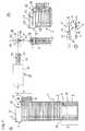
- FIG 1is a schematic side view of a particularly preferred embodiment of a lancet magazine (1), in which a side wall of the housing (3) is removed was given an insight into and into the lancet magazine (1) To allow lancets (2) and other functional components.
- the lancet magazine (1)has essentially the shape of an elongated, flat cuboid in which the lancets (2) are arranged linearly next to each other, each touching in pairs.
- the lancetscan be pushed manually to the removal point (4) using a transport device (5), why on the outside of one of the long, narrow sides of the lancet magazine (1) an operating button (6) is provided for the transport device (5).
- Moving the Transport device (5) using the control button (6)can be continuous or discontinuously, for example rasterized. The position of the control button (6) allows the current level of the magazine (1) to be recognized.
- a guide groove (7)is contained within the lancet magazine (1), in which the transport device (5) and the protective sleeves (14) of the lancets (2) are guided.
- the protective covers (14), the transport device (5) and the guide groove (7)are together in size and shape adjusted accordingly.
- the guide groove (7) and the stop (8)can also in the inside of the Lancet magazine (1) facing side surface of the housing (3) may be included, which is shown in FIG was removed to allow an insight into the lancet magazine.
- FIG. 2shows a lancet (2) which is in a lancet magazine (1) according to FIG. 1 can be accommodated. While the lancet (2) in Figure 1 in a side view is shown schematically, there is a schematic plan view of a lancet in Figure 2 (2).
- the lancet (2)consists essentially of a metal needle (11) with a tip that is covered by a protective cover (14). This protective cover (14) must be used before Lancet (2) for collecting blood can be removed from the lancet (2).
- the lancet (2)also contains one on the side opposite the protective cover (14) Lancet body (12) which contains a pin (13) on both sides.
- the lancet body (12)is preferably and the protective cover (14) is made of an injection-moldable plastic.
- Figure 3shows schematically based on 7 partial figures (A to G), such as with the help of a lancing device (15) a lancet (2) which is located at the removal point (4) of a lancet magazine (1), is removed from the lancet magazine (1).
- the lancing device (15)has essentially the shape of a fountain pen. It contains a handle body as essential components (16), a tip (17) and a protective cap (18). In the handle body (16) are for Movable mechanical components of the lancing device (15) required for the lancing movement. These correspond largely to the state of the art, for example EP A-0 565 970, and are not to be explained in more detail here.
- the Lancet holder (19)housed in the tip (17) after pulling off or unscrewing the protective cap (18) from the lancing device (15).
- the lancet holder (19) of the present Particularly preferred embodiment of a lancing device (15)are the flexible holding tongue (20) with a barb and the ejector (21), since these components of the lancet holder (19) interact directly with the lancet (2) in the lancet magazine (1).
- the tip (17) of the Lancing devicefree ( Figure 3 A).
- the lancing device (15)is with its tip (17) ahead on the Lancet magazine (1) is moved, in which a lancet (2) is located at the removal point (4) ( Figure 3 B).
- the tip (17) of the lancing device (15)has a recess which makes it possible that the tip (17) can be pushed over the lancet magazine (1). It penetrates the lancet holder (19) through the opening (9) into the lancet magazine.
- the flexible Retaining tongue (20)slides over the lancet (2) located at the removal point (4), wherein the retaining tongue (20) is slightly bent upwards (Figure 3 C).
- the lancing device (15) with the Protective cap (18)are closed.
- the lancing device (15)can be turned by turning the Protective cap (18) can be tensioned automatically. It is therefore available for blood collection.
- FIG. 4 Ashows a further, particularly preferred embodiment of the invention Lancet magazine (1) shown in a side view, in which the lancet magazine (1) partially is cut.
- the lancet magazine (1)has essentially the shape of an elongated one flat cuboids. Similar to the embodiment in FIG Lancets (2) arranged essentially linearly side by side, touching in pairs.
- the Lancets (2)are placed over a transport device (5), which essentially consists of a plate (25) and two this plate (25) driving coil springs (26), automatically in Direction of the tapping point (4).
- a transport device (5)which essentially consists of a plate (25) and two this plate (25) driving coil springs (26), automatically in Direction of the tapping point (4).
- In the area of the tapping point (4)is one second transport device (5 ') is provided.
- Thisessentially consists of a movable one Housing part (27), which by a coil spring (26) in the rest position shown is held.
- the transport device (5 ')In the area of the transport device (5 ') there is also the Opening (9) for inserting the lancing device and the opening (10) for ejecting the protective cover (14) of the lancets (2), which also serves the flexible tongue (38), which is movable on the housing (3) of the lancet magazine (1) is attached. Also part of the transport device (5 ') is a gripper system (28) which is the uppermost, that is, the removal point (4) closest lancet (2) grips when operating the transport device (5 ').
- FIG. 4 Bare detailed drawings of schematic views of the lancing device (15) in side and Frontal view and that part of the lancet magazine (1) shown in which the Lancing device (15) for removing a lancet (2) can be inserted.
- the lancing device (15) shown abovelike the lancing device (15) from FIG. 3A, is only shown with the part, which is relevant to the invention. Here, too, the other functional ones correspond State of the art components.
- the lancing device (15)contains a handle body (16) and a tip (17) in which a lancet holder (19) is accommodated, which in turn is a has flexible retaining tongue (20).
- these parts of the lancing device (15)are partial can be seen in a side view.
- Right of the side view in Figure 4 Bis a top view of the lancing device (15).
- the supervisionclarifies the relative position of the components already mentioned to each other.
- the guide groove (30)is closed see that is provided in the lancing device tip (17).
- FIG. 4BBelow this frontal view of the lancing device (15) in FIG. 4B is a frontal detailed view the opening (9) of the lancet magazine (1) can be seen. On the right there is a partial one sectioned side view of the lancet magazine (1). Frontal view of the opening (9) of the lancet magazine (1) are in particular the gripper system (28) and the guide pin (29) recognizable.
- the gripper system (28)consists of two movable, barbed provided tongues, the one when depressing the movable housing part (27) by a holding device (32), which is laterally as a hemispherical elevation from the inner surface the housing wall of the lancet magazine (1) protrudes in the provisional removal position (31) Hold the lancet (2) and hold it so that when you relax the Coil spring (26) and the resulting sliding back of the movable housing part (27) in the starting position, a lancet (2) is taken into the final removal position (33) becomes.
- the flexible tongue (38)is pressed outwards, whereupon it becomes moved back to its slightly inward inclined rest position.
- the guide pin (29)moves when inserting the lancing device (15) into the opening (9) in the guide groove (30) in the tip (17) of the lancing device (15). This ensures on the one hand that the lancing device (15) is inserted into the opening (9) in the correct orientation.
- On the other handcan be achieved by suitable geometry of the guide groove (30) that the lancing device (15) when inserted into the lancet magazine (1) via the opening (9) rotates about its longitudinal axis. In this way, the lancet (2), which is in the removal position (33), is turned around their longitudinal axis rotated.
- the protective sheath (14) of the lancet (2)as shown in FIG. 4 C and D is shown, are twisted off the rest of the lancet (2) and thus the metal needle (11) or release their tip.
- the particularly preferred embodiment of the lancet (2) shown in FIGS. 4 C and Dconsists essentially of a metal needle (11), which in this case is largely complete is surrounded by a plastic body (12).
- the protective cover (14)is part of the Plastic body (12), being at the junction between the protective cover (14) and the remaining plastic body (12) a predetermined breaking point is provided which when the Protective cover (14) relative to the plastic body (12) allows the protective cover (14) to be removed.
- preferred Embodimentare the lancets (2) - similar to staples - over glue points connected to one another on the elevations (24) to form a set of lancets.
- Means (22, 23)are provided in the lancet body (12) into the parts of the lancet holder (19) can intervene in order to hold the lancet (2) firmly in the lancet holder (19).
- the Lancet body (12) in the illustrated, particularly preferred embodiment of the The lancet (2)contains a funnel-shaped notch (22) and a pair of opposing ones V-shaped recesses (23). The barb can be inserted into the funnel-shaped notch (22) engage the movable tongue (20) of the lancet holder (19) of the lancing device (15) and hold the lancet (2) in this way.
- the V-shaped recesses (23)can be used together with alternative embodiments of the lancet holder (19) of a lancing device, not shown here (15) can be used.
- the lancet magazine (1) of the preferred embodiment shown in FIG. 4can be opened by the user in order to insert a new set of lancets.
- the housing of the lancet magazine (1)can be folded away by folding the transport device (5 ) can be opened.
- the lancets (2)are pushed individually or releasably together as a lancet set into the magazine (1).
- the transport device (5)is tensioned again by compressing the coil springs (26). Finally, the transport device (5th ) folded back.
- the magazine (1)is thus ready for use.
- FIG. 5analogously to FIG. 3, ten partial figures (A to K) are shown, as with the help of a lancing device (15), a lancet (2) from a lancet magazine (1), which is the particular one preferred embodiment of Figure 4 A corresponds, can be seen;
- the protective cap (18)must be removed from the lancing device (15) before the lancet is removed or unscrewed so that the tip (17) of the lancing device is exposed ( Figure 5 A).
- the Lancetwhich is in the provisional removal position (31) and there by the holding device (32) is held, gripped ( Figure 5 B) and when sliding back the movable Housing part (27) in its original position by bending the movable tongue outwards (38) moved to the final removal position (33), where it is held by the gripper system (28) becomes.
- the remaining lancets located in the lancet magazine (1)are replaced by the automatic transport device (5) (see FIG.
- the protective cover (14)is of this However, rotation is excluded as it is due to the gripper system (28) and the flexible tongue (38) is fixed in its position and therefore cannot perform the rotary movement.
- the The lancet body (12)is turned against the protective cover (14), causing the predetermined breaking point breaks between lancet body (12) and protective cover (14) ( Figure 5 E).
- the protective cover (14)is separated from the rest of the lancet (2) and remains first in the gripper system (28) ( Figure 5 F).
- the tip of the metal needle (11) and parts of the In this particularly preferred embodiment, the lancet body (12)protrudes from the Tip (17) of the lancing device (15) out.
- the protective cap (18)By replacing the protective cap (18) the exposed tip of the metal needle (11) covered ( Figure 5 G). If necessary, at the same time for example, the lancing device (15) is tensioned by rotating the protective cap (18) become.
- the protective sheath (14) of the lancet (2) that remains in the gripper system (28)is replaced when it is replaced Depressing the movable housing part (27) to remove another lancet (2) from the provisional removal position (31) through the movable tongue (38) from the gripper system (28) pushed out (Figure 5 H) and is initially loosely on the next to the final Removal position to be transported lancet (2) (Figure 5 I), from where it is easy can be removed ( Figure 5 K).
- the lancet magazine (1) of this preferred embodimenthas essentially the shape of a flat, round disc to which an insertion piece (37) is attached a lancing device for removing lancets (2) into the lancet magazine via the opening (9) (1) can be introduced.
- a transparent viewing window (34)is provided, which allows the current Check the fill level of the lancet magazine (1) with lancets (2).
- the viewing window (34)can consist of a transparent plastic connected to the housing (3). It is however, it is also possible that the entire housing (3) is made of a transparent plastic is.
- the viewing window (34)can only be used as an open recess of the housing (3).
- a transport devicecan be operated using an operating button (6) (5) are operated, for example via a spiral spring lancets in the removal position (33) brings.
- Inside the opening (9) of the insertion nozzle (37)can again a guide pin (29) can be provided which interacts with one Guide groove in the lancing device can occur.
- the lancet set (35)consists of a large number of lancets (2), which are star-shaped around a circular, central one Plastic disc (36) are arranged. The tips of the metal needles (11) are inserted Lancets (2) in the central plastic disc (36). The lancets themselves correspond to essentially the lancets, as shown in FIG. 4C. Again, there are V-shaped ones Recesses (23) are provided in the lancet body (12), which interact with enable the lancet holder of a lancing device.
- the lancet magazine (1) of the preferred embodiment shown in FIGS. 6A and Bcan be opened by the user to create a new set of lancets (35) to insert.
- the housing of the lancet magazine (1)can be removed by removing the upper, i.e. H. be opened with a window provided.
- the lancets (2)are inserted as a lancet set (35).
- the spiral spring of the transport device (5)is tensioned.
- the removed housing halfis attached to the magazine (1) again, for example by Clipping.
- the magazine (1)is thus ready for use.
- FIG. 7 -analogously to FIG. 3 and FIG. 5 - is schematically based on 6 partial figures (A to F) shown as with a lancing device (15) lancets (2) from the particularly preferred
- the lancet magazine (1) according to FIG. 6can be removed:
- the tiplies (17) with the guide groove (30) and the lancet holder (19) of the lancing device (15) are free (FIG. 7 A).
- the lancing device (15)can now in the opening (9) of the insertion (37) of the Lancet magazine (1) are introduced.
- the guide groove (30) in the tip (17)the lancing device (15) in interaction with the guide pin (29) in the opening (9) of the Lancet magazine (1) for a clear orientation of the lancing device (15) relative to the Lancet magazine (1).
- the lancet (2)is in the removal position gripped by the lancet holder (19) ( Figure 7 B and C).
- the lancet (2)By turning the lancing device (15), which is caused by the contour of the guide groove (30), the lancet (2) is put together with the lancing device (15) rotated about its longitudinal axis.
- the tip of the metal needle (11)rotated in the plastic disc (36) and thus released ( Figure 7 D).
- Figure 7 EWhen removing the lancing device (15) from the lancet magazine (1) removes the lancet (2) from the Lancet holder (19) held in the lancing device (15) ( Figure 7 E).
- the tip of the metal needle (11) and the part of the lancet body closest to the tip of the metal needle (11) (12)protrude from the lancet holder in this particularly preferred embodiment (19) of the lancing device (15).
- the protective capTo tighten the lancing device (15), the protective cap must again be used (18) pushed over the tip (17) with lancet holder (19) of the lancing device (15) and can be rotated relative to the handle body (16).
Landscapes
- Health & Medical Sciences (AREA)
- Life Sciences & Earth Sciences (AREA)
- Engineering & Computer Science (AREA)
- Molecular Biology (AREA)
- Animal Behavior & Ethology (AREA)
- Pathology (AREA)
- Physics & Mathematics (AREA)
- Biomedical Technology (AREA)
- Heart & Thoracic Surgery (AREA)
- Medical Informatics (AREA)
- Hematology (AREA)
- Surgery (AREA)
- Biophysics (AREA)
- General Health & Medical Sciences (AREA)
- Public Health (AREA)
- Veterinary Medicine (AREA)
- Dermatology (AREA)
- Diabetes (AREA)
- Manufacturing & Machinery (AREA)
- Measurement Of The Respiration, Hearing Ability, Form, And Blood Characteristics Of Living Organisms (AREA)
- Investigating Or Analysing Biological Materials (AREA)
Abstract
Description
Translated fromGermanDie Erfindung betrifft ein System geeignet zur Gewinnung einer Körperflüssigkeit, insbesonderevon Blut, aus einer Körperpartie einer zu untersuchenden Person, wobei das Systemeine Stechhilfe, zwei oder mehrere Lanzetten und ein Lanzettenmagazin zur Bevorratung vonzwei oder mehreren Lanzetten enthält. Die Erfindung betrifft weiterhin eine Stechhilfe,Lanzetten und ein Lanzettenmagazin, die zum Einsatz in dem erfindungsgemäßen System geeignetsind, sowie ein spezielles Verfahren zur Entnahme einer Lanzette aus einem Lanzettenmagazin.The invention relates to a system suitable for obtaining a body fluid, in particularof blood, from a part of the body of a person to be examined, the systema lancing device, two or more lancets and a lancet magazine for storingcontains two or more lancets. The invention further relates to a lancing device,Lancets and a lancet magazine, which are suitable for use in the system according to the inventionare, as well as a special method for removing a lancet from a lancet magazine.
Die Untersuchung von Blutproben ermöglicht in der klinischen Diagnostik das frühzeitige undzuverlässige Erkennen von pathologischen Zuständen sowie die gezielte und fundierte Kontrollevon Körperzuständen. Die medizinische Blutdiagnostik setzt stets die Gewinnung einerBlutprobe des zu untersuchenden Individuums voraus. Während in Kliniken und bei niedergelassenenÄrzten oftmals durch eine Venenpunktion mehrere Milliliter Blut einer zu untersuchendenPerson für die Analyse gewonnen werden, um damit eine Vielzahl von Labortestsdurchführen zu lassen, reichen für einzelne Analysen, die gezielt aufeinen Parameter gerichtetsind, heutzutage oftmals wenige Mikroliter Blut aus. Solch geringe Blutmengen erfordernkeine Venenpunktion. Vielmehr genügt es hier, zur Blutgewinnung durch die Haut z. B. in dieFingerbeere oder das Ohrläppchen der zu untersuchenden Person mit Hilfe einer sterilen,scharfen Lanzette zu stoßen, um so einige wenige Mikroliter Blut für die Analyse zu gewinnen.Insbesondere eignet sich diese Methode, wenn die Analyse der Blutprobe unmittelbar nach derBlutgewinnung durchgeführt werden kann.The examination of blood samples enables early and clinical diagnosisreliable detection of pathological conditions as well as targeted and well-founded controlof body conditions. Medical blood diagnostics always involve the acquisition of oneBlood sample of the individual to be examined beforehand. While in clinics and at residentDoctors often use several milliliters of blood to be examined through a venipuncturePerson obtained for analysis to do a variety of laboratory testsletting them be carried out are sufficient for individual analyzes that are aimed specifically at one parameterare often out of a few microliters of blood these days. Require such small amounts of bloodno venipuncture. Rather, it is sufficient here to obtain blood through the skin such. B. in theFingertip or the earlobe of the person to be examined using a sterile,sharp lancet so as to collect a few microliters of blood for analysis.This method is particularly suitable if the analysis of the blood sample immediately after theBlood collection can be done.
Vor allem im Bereich des sogenannten "Home-Monitoring", also dort, wo medizinische Laienselbst einfache Analysen des Bluts durchführen, und dort insbesondere für die regelmäßige,mehrmals täglich durchzuführende Blutgewinnung durch Diabetiker für die Kontrolle der Blutglucosekonzentration, werden Lanzetten und dazu passende Geräte (sogenannte Blutentnahmegeräte,Blutlanzettenvorrichtungen oder - wie sie im Folgenden genannt werden sollen -Stechhilfen), angeboten, die eine möglichst schmerzarme und reproduzierbare Blutgewinnungermöglichen. Zudem soll die Verwendung von Lanzetten mit Stechhilfen die psychologischeSchwelle beim Stechen des eigenen Körpers senken, was vor allem für Kinder, die an Diabeteserkrankt sind und auf regelmäßige Blutglucosetests angewiesen sind, von besonderer Bedeutungist. Als Beispiele für Lanzetten und Stechhilfen seien die kommerziell erhältlichenGeräte und Lanzetten Glucolet® der Bayer AG und Softclix® der Boehringer Mannheim GmbHgenannt. Solche Lanzetten und Geräte sind z. B. Gegenstand von EP-A 0 565 970,US 4,442,836 oder US 5,554,166.Especially in the area of so-called "home monitoring", that is, wherever medical laypeopleperform simple blood analyzes themselves, and there in particular for regular,Blood taken several times a day by diabetics to control the blood glucose concentration,lancets and matching devices (so-called blood collection devices,Blood lancet devices or - as they will be called in the following -Lancing devices), which offer the least painful and reproducible blood collection possibleenable. In addition, the use of lancets with lancing devices is said to be psychologicalLower threshold of stinging your own body, especially for children with diabetesare sick and rely on regular blood glucose tests, of particular importanceis. Examples of lancets and lancing devices are those that are commercially availableDevices and lancets Glucolet® from Bayer AG and Softclix® from Boehringer Mannheim GmbHcalled. Such lancets and devices are e.g. B. Subject of EP-A 0 565 970,US 4,442,836 or US 5,554,166.
Bei den derzeit verfügbaren Systemen erfolgt die Bereitstellung der Lanzetten für die Verwendungin Stechhilfen meist in loser Form. Der Benutzer entnimmt manuell vorjedem Stechvorgangeine Lanzette aus einer Verpackung, beispielsweise einer Pappschachtel oder einerRöhre, in der eine Vielzahl von Lanzetten ungeordnet, lose geschüttet enthalten sind. Anschließendwird die Stechhilfe, beispielsweise durch Abschrauben oder Abziehen einer Schutzkappe,für die Aufnahme der Lanzette vorbereitet, wobei der Lanzettenhalter der Stechhilfefreigelegt wird. Der Lanzettenhalter dient einerseits der Aufnahme der Lanzetten. Andererseitswird durch ihn die Lanzette beim eigentlichen Stechvorgang geführt. Die aus der Packung entnommeneLanzette wird manuell in den Lanzettenhalter der Stechhilfe eingeführt und dortfixiert. Dann muß die Schutzhülle, welche die Lanzettenspitze umgibt und sowohl diese alsauch den Benutzer schützt, von der Lanzette manuell abgenommen werden. Anschließend wirddie Stechhilfe mit ihrer Schutzkappe wieder verschlossen. Die Schutzkappe sorgt dafür, daßdie Lanzette von außen nicht mehr zugänglich ist. Sie besitzt meist eine Öffnung, durch welchedie Lanzettenspitze beim eigentlichen Stechvorgang austreten kann. Schließlich wird dieStechhilfe gespannt und steht für den Stechvorgang zur Gewinnung von Blut zur Verfügung.With the currently available systems, the lancets are made available for useusually in loose form in lancing devices. The user removes manually before each lancing processa lancet from a packaging, for example a cardboard box or oneTube in which a large number of lancets are disorderly, loosely poured. Subsequentlythe lancing device, for example by unscrewing or pulling off a protective cap,prepared for the lancet, the lancet holder of the lancing deviceis exposed. The lancet holder is used to hold the lancets. On the other handthe lancet is guided through it during the actual lancing process. The one taken from the packThe lancet is inserted manually into the lancet holder of the lancing device and therefixed. Then the protective sheath that surrounds the lancet tip and both this andalso protects the user, can be removed manually from the lancet. Then willclosed the lancing device with its protective cap. The protective cap ensures thatthe lancet is no longer accessible from the outside. It usually has an opening through whichthe lancet tip can escape during the actual lancing process. Finally, theLancing device is tensioned and is available for the lancing process to obtain blood.
Die Vielzahl der manuellen Bedienschritte wird vom Benutzer als nachteilig empfunden und istvor allem bei eingeschränkter Wahrnehmung im Zustand einer Hypoglykämie problematisch.Zudem wird der Benutzer dazu verleitet, eine einmal eingelegt Lanzette mehrfach zum Stechen und Blutgewinnen zu verwenden. Dies ist zum einen aus hygienische Gründen bedenklich. Zumanderen führt die mehrmalige Benutzung der Lanzetten zu steigendem Schmerz für den Benutzer,denn da die Lanzetten als Einmalartikel konzipiert sind, werden sie schnell stumpf Zudembesteht mit den Stechhilfen und Lanzetten des Standes der Technik die Gefahr, daßStechhilfen mit nicht passenden Lanzetten benutzt werden oder daß die Lanzetten unsachgemäßin die Stechhilfen eingelegt werden. Weiterhin kann sich ein Benutzer bei unsachgemäßeBenutzung von Lanzetten und Stechhilfen unbeabsichtigt verletzen.The large number of manual operating steps is perceived and disadvantageous by the userparticularly problematic with limited perception in the state of hypoglycemia.In addition, the user is tempted to lance a lancet once inserted several timesand use blood collection. On the one hand, this is questionable for hygienic reasons. To theothers the repeated use of the lancets leads to increasing pain for the user,Because the lancets are designed as single-use items, they quickly become dullwith the lancing aids and lancets of the prior art there is a risk thatLancing devices with incompatible lancets are used or that the lancets are improperbe inserted into the lancing devices. Furthermore, a user can get improperInadvertently injure the use of lancets and lancing devices.
Es mangelt deshalb nicht an Versuchen, die angesprochenen Nachteile zu beseitigen. Aus denUS-Patentschriften US 3,030,959, US 4,794,926, US 5,035,704 und US 5,152,775 sindStechhilfen bekannt, die mehrere Lanzetten in sich bevorraten und diese nacheinander einzelnfür Stechvorgänge benutzen können. Aus US 5,514,152 und WO 98/14125 sind miteinanderverbundene Lanzetten bekannt, die gemeinsam in eine Art Stechhilfe eingeführt werdenkönnen. Die in diesen Schriften vorgeschlagenen Konzepte können die angesprochenenProbleme jedoch nur partiell lösen und erzeugen teilweise selbst neue Nachteile wie aufwendigeKostruktion von Stechhilfe und/oder Lanzetten, mangelnde Hygiene und/oder Sterilitätund ungenügenden Bedienkomfort.There is therefore no shortage of attempts to eliminate the disadvantages mentioned. From theU.S. Patents US 3,030,959, US 4,794,926, US 5,035,704 and US 5,152,775Lancing devices are known which hold several lancets in themselves and these one after the othercan use for lancing processes. From US 5,514,152 and WO 98/14125 are togetherconnected lancets known that are inserted together in a kind of lancing devicecan. The concepts proposed in these writings can address those discussedHowever, only partially solving problems and sometimes creating new disadvantages such as complex onesConstruction of lancing device and / or lancets, poor hygiene and / or sterilityand insufficient ease of use.
Aufgabe der Erfindung ist es, die Nachteile des Standes der Technik zu beseitigen. Insbesondereist es die Aufgabe der vorliegenden Erfindung, die Anzahl der manuellen Bedienschrittebeim Einlegen einer Lanzette in eine Stechhilfe zu reduzieren und somit den Bedienkomfortfür den Benutzer zu erhöhen. Zudem ist es Aufgabe der Erfindung, ein verwechslungsfreiesEinlegen der Lanzette in die Stechhilfe zu gewährleisten und die Sicherheitfür den Benutzer im Umgang mit Stechhilfe und Lanzette, insbesondere bei hypoglykämischeZuständen, zu erhöhen.The object of the invention is to eliminate the disadvantages of the prior art. In particularit is the object of the present invention, the number of manual operating stepsreduce when inserting a lancet into a lancing device and thus the ease of usefor the user to increase. In addition, it is an object of the invention to ensure a mix-upInsert the lancet into the lancing device to ensure safetyfor the user in dealing with lancing device and lancet, especially with hypoglycemicConditions to increase.
Die Aufgabe wird durch den Gegenstand der Erfindung, wie er in den Patentansprüchencharakterisiert ist, gelöst.The object is achieved by the subject matter of the invention as set out in the claimsis characterized, solved.
Gegenstand der Erfindung ist ein System geeignet zur Gewinnung einer Körperflüssigkeit, insbesonderevon Blut aus einer Körperpartie einer zu untersuchenden Person enthaltend eineStechhilfe, die zur Aufhahme einer Lanzette geeignet ist, ein Lanzettenmagazin zur Bevorratungvon zwei oder mehreren Lanzetten, das eine Transportvorrichtung für die Lanzettenaufweist und eine Öffnung besitzt, in welche die Stechhilfe zur Entnahme einer Lanzette ausdem Lanzettenmagazin eingeführt werden kann, und zwei oder mehrere Lanzetten.The invention relates to a system suitable for obtaining a body fluid, in particularof blood from a part of the body of a person to be examined containing oneLancing device that is suitable for holding a lancet, a lancet magazine for storageof two or more lancets, which is a transport device for the lancetshas and has an opening into which the lancing device for removing a lancetthe lancet magazine can be inserted, and two or more lancets.
Das erfindungsgemäße System ist zur Gewinnung einer Körperflüssigkeit, insbesondere vonBlut, einer zu untersuchenden Person geeignet. Dabei durchstößt die von der Stechhilfe gehaltene,geführte und angetriebene Lanzette kurzzeitig und mit definierter Einstichtiefe dieHaut dieser Person, wodurch eine winzige Wunde entsteht. Auf der Oberfläche der Wundesammelt sich ein Tropfen der Körperflüssigkeit, insbesondere Blut von in aller Regel wenigenMikroliter bis maximal 100 Mikroliter Volumen. Vorzugsweise wird die Körperflüssigkeitdirekt im Anschluß an die Gewinnung für eine diagnostische Untersuchung eingesetzt. DieProbe der Körperflüssigkeit kann jedoch auch für eine spätere Untersuchung aufbewahrtwerden.The system according to the invention is for obtaining a body fluid, in particular fromBlood, suitable for a person to be examined. The lancing device held by the lancing deviceguided and driven lancet for a short time and with a defined insertion depthSkin of this person, causing a tiny wound. On the surface of the woundA drop of body fluid, especially blood, is usually collected from a fewMicroliters up to a maximum of 100 microliters volume. Preferably the body fluidused immediately after the extraction for a diagnostic examination. TheHowever, sample of the body fluid can also be kept for later examinationbecome.
Insbesondere kann mit dem erfindungsgemäßen System Kapillarblut aus einer Körperpartie,wie z. B. einer Fingerbeere oder einem Ohrläppchen, gewonnen werden. Das System kannsowohl von der zu untersuchenden Person selbst, beispielsweise einem Diabetiker, der seinenBlutglucosegehalt bestimmen möchte, als auch von einem Dritten, z. B. einem Arzt oder einerKrankenschwester zur Gewinnung von Blutproben eines Patienten, angewendet werden.In particular, capillary blood from a part of the body,such as B. a fingertip or an earlobe. The system canboth by the person to be examined himself, for example a diabetic who has hisWant to determine blood glucose content, as well as from a third party, e.g. B. a doctor or aNurse used to collect blood samples from a patient.
Das erfindungsgemäße System enthält eine Stechhilfe, Lanzetten und ein Lanzettenmagazin,die in ihrer Form und Funktion so aufeinander abgestimmt sind, daß ein optimales Zusammenwirkender einzelnen Systemkomponenten miteinander erreicht wird. Die einzelnen Komponentenund deren Zusammenwirken sollen im Folgenden näher erläutert werden.The system according to the invention contains a lancing device, lancets and a lancet magazine,which are coordinated in their form and function so that an optimal interactionof the individual system components is achieved with each other. The individual componentsand their interaction will be explained in more detail below.
Zentrale Komponente des erfindungsgemäßen Systems ist das Lanzettenmagazin. Es dient derAufnahme, Aufbewahrung und dem Zurverfügungstellen der Lanzetten und stellt die fünktionaleVerbindung zwischen Lanzetten und Stechhilfe her. Zur Erfüllung dieser Zwecke besitztdas Lanzettenmagazin
- ein Gehäuse, in dem die Lanzetten aufbewahrt werden,
- eine Entnahmestelle für eine Lanzette und gegebenenfalls Mittel, die eine Lanzette in derEntnahmestelle halten,
- eine Vorrichtung, mit der die Lanzetten manuell oder automatisch in die Entnahmestelletransportiert werden können,
- eine Öffnung, in welche die Stechhilfe mit ihrer Spitze zur Entnahme einer Lanzette eingeführtwerden kann und die gegebenenfalls Mittel zur Führung der Stechhilfe enthält,
- gegebenenfalls eine weitere, vorzugsweise der Öffnung für die Stechhilfe gegenüberliegendeÖffnung, durch welche die Schutzhülle der Lanzettennadeln nach deren Entnahme mit Hilfe derStechhilfe aus dem Inneren des Lanzettenmagazins entfernt werden kann, und
- gegebenenfalls eine verschließbare Öffnung, durch die Lanzetten in das Magazin gefülltwerden können.
- a housing in which the lancets are kept,
- a removal point for a lancet and, if appropriate, means which hold a lancet in the removal point,
- a device with which the lancets can be transported manually or automatically to the removal point,
- an opening into which the lancing device can be inserted with its tip for removing a lancet and which may contain means for guiding the lancing device,
- optionally a further opening, preferably opposite the opening for the lancing aid, through which the protective cover of the lancet needles can be removed from the interior of the lancet magazine with the aid of the lancing device, and
- if necessary, a closable opening through which lancets can be filled into the magazine.
Vorzugsweise dient das Lanzettenmagazin nicht vordringlich der Sterilität der Lanzetten. Diesewird vorzugsweise durch geeignete konstruktive Maßnahmen an der Lanzette selbst verwirklicht,beispielsweise durch Einsiegeln der Lanzettenspitze in eine abnehmbare, dichteKunststoffschutzhülle.The lancet magazine preferably does not primarily serve the sterility of the lancets. Thisis preferably implemented by suitable constructive measures on the lancet itself,for example by sealing the lancet tip into a removable, sealed onePlastic protective cover.
Das Gehäuse des Lanzettenmagazins ist aus einem Metall, beispielsweise Aluminium, odereinem Kunststoff, z. B. Polypropylen oder Polyethylen, gefertigt. Vorzugsweise ist dasGehäuse mittels Spritzguß aus einem spritzgußfähigen Material, insbesondere Kunststoff, gefertigt.Das Gehäuse kann prinzipiell jede für die Funktion des Lanzettenmagazins geeigneteForm haben. Als bevorzugt hat es sich herausgestellt, daß das Lanzettenmagazin entweder dieForm eines länglichen, flachen Quaders, also ähnlich einer Zigarettenschachtel, oder die Form einer flachen quadratischen, vieleckigen oder runden Scheibe, z. B. ähnlich einer Puderdose,aufweist. Selbstverständlich können Kanten und Ecken des Gehäuses aus Design- oderErgonomiegründen abgerundet sein. Die Dimensionen des Lanzettenmagazins werden imwesentlichen durch die Größe der Lanzetten und die Anzahl der zu bevorratenden Lanzettenbestimmt. Erfindungsgemäß können zumindest zwei Lanzetten im Magazin aufbewahrtwerden. Vorzugsweise dient das Lanzettenmagazin der Bevorratung von 10 bis 200 Lanzetten.Besonders bevorzugt enthält es 20 bis 50 Lanzetten.The housing of the lancet magazine is made of a metal, for example aluminum, ora plastic, e.g. B. polypropylene or polyethylene. Preferably that isHousing made by injection molding from an injection moldable material, especially plastic.The housing can in principle be any suitable for the function of the lancet magazineTo have shape. It has been found to be preferred that the lancet magazine either theThe shape of an elongated, flat cuboid, similar to a box of cigarettes, or the shapea flat square, polygonal or round disc, e.g. B. similar to a powder jar,having. Of course, edges and corners of the housing can be made of design orErgonomic reasons should be rounded. The dimensions of the lancet magazine are inessentially by the size of the lancets and the number of lancets to be storedcertainly. According to the invention, at least two lancets can be stored in the magazinebecome. The lancet magazine is preferably used to store 10 to 200 lancets.It particularly preferably contains 20 to 50 lancets.
In einer bevorzugten Ausführungsform hat das Lanzettenmagazins die Form eines flachen,länglichen Quaders. Die kurzen, schmalen Flächen entsprechen in Länge und Breite den entsprechendenDimensionen einer einzelnen Lanzette; die langen, schmalen Flächen entsprechenin ihrer Breite der Breite einer Lanzette und in ihrer Länge mindestens der Summe der Höhender Lanzetten, die im Magazin untergebracht werden sollen. Die Dimensionen der großenQuaderflächen ergeben sich entsprechend. Die Lanzetten sind in dieser bevorzugten Ausführungsformim Magazin sich paarweise berührend neben- bzw. übereinander oder sichgegenüberliegend, z. B. Kopfan Kopf, gestapelt und können sowohl einzeln als auch lösbarmiteinander zu einem Lanzettensatz verbunden vorliegen, beispielsweise durch Verkleben oderVerschweißen der einzelnen Lanzetten an ihren Berührungsstellen, ähnlich also wie Heftklammernmiteinander zu einem Satz verbunden sind, oder durch Verbindung über dünneKunststoffstege.In a preferred embodiment, the lancet magazine has the shape of a flat,oblong cuboid. The short, narrow areas correspond in length and width to the corresponding onesDimensions of a single lancet; the long, narrow areas correspondin width the width of a lancet and in length at least the sum of the heightsthe lancets to be placed in the magazine. The dimensions of the big onesCuboid areas result accordingly. The lancets are in this preferred embodimentin the magazine touching each other in pairs next to or on top of each otheropposite, e.g. B. head to head, stacked and can be both individually and detachablyare connected to one another to form a lancet set, for example by gluing orWelding of the individual lancets at their contact points, similar to staplesconnected to each other in a sentence, or by connection via thinPlastic webs.
In einer alternativen, ebenfalls bevorzugten Ausführungsform hat das Lanzettenmagazin dieForm einer flachen quadratischen, regelmäßig oder unregelmäßig vieleckigen oder rundenScheibe. Die Lanzetten sind in dieser Ausführungsform vorzugsweise sternförmig in einerEbene um eine zentrale Achse angeordnet, wobei besonders bevorzugt die Lanzettenspitzen ineiner gemeinsamen, zentralen Kunststoffscheibe stecken und die Lanzetten so miteinander zueiner Lanzettenscheibe verbunden sind. Auf diese Weise werden zudem die Lanzettenspitzensteril gehalten.In an alternative, likewise preferred embodiment, the lancet magazine has theForm a flat square, regular or irregular polygonal or roundDisc. In this embodiment, the lancets are preferably star-shaped in onePlane arranged around a central axis, the lancet tips in particularly preferably input a common, central plastic disc and the lancets togethera lancet disk are connected. In this way, the lancet tips are alsokept sterile.
Unabhängig von der äußeren Form des Lanzettenmagazins - ob quaderförmig oder scheibenförmig- besitzt das erfindungsgemäße Lanzettenmagazin eine Entnahmestelle oder -positionfür eine Lanzette. In diese Position wird mit Hilfe einer im Magazin enthaltenen Transportvorrichtungeine Lanzette zur Entnahme durch die Stechhilfe befördert. Die Transportvorrichtungdient dazu, nach der Entnahme einer Lanzette aus dem Magazin die nächste, d. h. die der entnommenenLanzette ursprünglich benachbarte, im Magazin enthaltene Lanzette an die Entnahmestelledes Magazins zu befördern. Dabei kann die Transportvorrichtung dieses Befördernder nächsten Lanzette zur Entnahmestelle automatisch bewerkstelligen, so daß jederzeitsolange Lanzetten im Magazin enthalten sind eine Lanzette in der Entnahmeposition ist, oderaber das Befördern der nächsten Lanzette geschieht nicht automatisch, durch die Entnahmeeiner Lanzette ausgelöst, sondern manuell durch den Benutzer. Der Transportmechanismuskann mit einem Zählwerk gekoppelt sein, der dem Anwender anzeigt, wieviele Lanzetten ausdem Magazin bereits verbraucht bzw. wieviele Lanzetten im Magazin noch vorrätig sind.Regardless of the outer shape of the lancet magazine - whether cuboid or disc-shaped- The lancet magazine according to the invention has a removal point or positionfor a lancet. In this position is with the help of a transport device contained in the magazinea lancet for removal by the lancing device. The transport deviceis used, after removing a lancet from the magazine, the next, d. H. that of the takenLancet originally adjacent, contained in the magazine lancet to the removal pointof the magazine. The transport device can transport thisthe next lancet to the tapping point automatically, so that at any timeas long as lancets are contained in the magazine, a lancet is in the removal position, orbut the transportation of the next lancet does not happen automatically by the removaltriggered by a lancet, but manually by the user. The transport mechanismcan be coupled to a counter that shows the user how many lancetsthe magazine has already been used or how many lancets are still in the magazine.
Die Transportvorrichtung kann in einer bevorzugten Ausführungsform sämtliche im Magazinverbleibenden Lanzetten nachrücken. In einer anderen Ausführungsform ist es jedoch möglich,immer nur eine, vorzugsweise die nächstgelegene, Lanzette zur Entnahniestelle weiterzutransportieren.In a preferred embodiment, the transport device can all in the magazinemove the remaining lancets up. In another embodiment, however, it is possibleOnly ever transport one, preferably the closest, lancet to the removal point.
In einer bevorzugten Ausführungsform werden die Lanzetten manuell mit Hilfe eines vonaußen zu bedienenden Schiebers in die Entnahmeposition gebracht. Der Schieber kann dabeikontinuierlich oder in diskreten Schritten, beispielsweise gerastert, mit Hilfe beispielsweiseeines Bedienungsknopfes in Richtung der Entnahmeposition bewegt werden und so die imMagazin enthaltenen Lanzetten transportieren. Die Lanzetten liegen dabei vorzugsweise miteiner Seitenfläche ganz oder teilweise auf dem im Magazin befindlichen Teil des Schiebers auf.In a preferred embodiment, the lancets are manually operated using one ofthe slide to be operated on the outside is brought into the removal position. The slider cancontinuously or in discrete steps, for example rasterized, with the help, for examplean operating button in the direction of the removal position and so the inTransport the lancets contained in the magazine. The lancets are preferably includeda side surface completely or partially on the part of the slide located in the magazine.
In einer weiteren bevorzugten Ausführungsform werden die Lanzetten mit Hilfe eines automatischenVorschubsystems, beispielsweise im Falle des quaderförmigen Magazins über einevon Schraubenfedern getriebene, linear verschiebbare Platte oder im Falle des scheibenförmigenMagazins über eine Spiralfeder, die so aufdie Lanzetten einwirkt, daß sie eine geführte, ebene Kreisbewegung ausführen, in die Entnahmeposition bewegt. Das automatischeVorschubsystem kann auch von einem Motor getrieben sein.In a further preferred embodiment, the lancets are automatedFeed system, for example in the case of the cuboid magazine over alinearly displaceable plate driven by coil springs or in the case of the disc-shapedMagazine about a spiral spring that acts on the lancets so that they have a guided,Carry out a flat circular movement, moved to the removal position. The automaticFeed system can also be driven by a motor.
Das Auslösen der Transportbewegung der Lanzetten im Magazin kann im Falle des automatischenVorschubsystems manuell, beispielsweise durch Betätigen eines Schalters, erfolgen.Es ist jedoch auch möglich, daß die Transportbewegung automatisch durch die Entnahme einerLanzette aus dem Magazin in Gang gesetzt wird.In the case of the automatic, the transport movement of the lancets in the magazine can be triggeredFeed system manually, for example by pressing a switch.However, it is also possible for the transport movement to take place automatically by removing aLancet from the magazine is started.
Sowohl in den inneren Magazinwänden als auch bei den Lanzetten können Anschläge sowieFührungsnuten und -zapfen oder -stege vorhanden sein, die für eine präzise Positionierung derLanzetten, insbesondere während des Transports der Lanzetten in die Entnahmeposition desMagazins, sorgen.Both in the inner magazine walls and in the lancets, stops as wellGuide grooves and journals or webs are present, which are used for precise positioning of theLancets, in particular during the transport of the lancets into the removal position of theMagazine, worry.
In einer weiteren, besonders bevorzugten Ausführungsform des erfindungsgemäßenLanzettenmagazins werden die Lanzetten mit Hilfe einer ersten Transportvorrichtung in einevorläufige Entnahmeposition gebracht, von der aus sie mittels eines zweiten Transportmechanismusin die endgültige Entnahmeposition bewegt werden. Die erste Transportvorrichtungkann dabei sowohl ein manuell zu bedienender Schieber als auch ein automatischesVorschubsystem sein. Die zweite Transportvorrichtung ist in dieser besonders bevorzugtenAusführungsform ein beweglicher Teil des Lanzettenmagazins, beispielsweise ein linearbewegliches, auf einer oder mehreren Federn gelagertes Teil des Gehäuses. Durch Druck aufdieses Gehäuseteil wird dieses auf eine in der vorläufigen Entnahmeposition befindlicheLanzette zubewegt und greift diese Lanzette mit einem Greifsystem, beispielsweise über einWiderhakensystem, welches gegebenenfalls an flexiblen Zungen angebracht ist, oder überMagnete. Beim Zurückgleiten des beweglichen Teils des Magazins wird die Lanzette in dieendgültige Entnahmeposition befördert und dort über das Greifsystem gehalten, bis dieLanzette mit Hilfe einer Stechhilfe aus dem Magazin entnommen wird.In a further, particularly preferred embodiment of the inventionLancet magazines are inserted into a lancet using a first transport deviceprovisional removal position, from which it is brought by means of a second transport mechanismbe moved into the final removal position. The first transport devicecan be both a manually operated slider and an automatic oneFeed system. The second transport device is particularly preferred in thisEmbodiment a movable part of the lancet magazine, for example a linearmovable part of the housing supported on one or more springs. By pressingthis part of the housing is placed in a position in the provisional removal positionMoves the lancet and grips this lancet with a gripping system, for example via aBarb system, which may be attached to flexible tongues, or overMagnets. When the movable part of the magazine slides back, the lancet is inserted into thefinal removal position is conveyed and held there via the gripping system until theLancet is removed from the magazine with the help of a lancing device.
Im Bereich der Entnahmestelle findet sich eine vorzugsweise verschließbare Öffnung imMagazin, in welche die Stechhilfe zumindest mit ihrer Spitze eingeführt werden kann, um so aus dem Inneren des Lanzettenmagazins eine einzelne Lanzette zu entnehmen. Geometrie undGröße der Öffnung richten sich nach den entsprechenden Dimensionen der Stechilfe. Vorzugsweisepassen Stechhilfe und Öffnung wie Schlüssel und Schloß zueinander, so daß eineeindeutige und präzise Ausrichtung dieser beiden Systemkomponenten während des Entnahmevorgangsgewährleistet ist. Um das Einführen der Stechhilfe in die Öffnung zuerleichtern, kann die Öffnung konisch oder trichterförmig gestaltet sein, so daß sie nach außenhin größer als für die Aufnahme der Stechhilfenspitze erforderlich ist. Es ist ebenfalls möglich,daß sich die Stechhilfe im Bereich ihrer Spitze, die in das Lanzettenmagazin eingeführt wird,verjüngt, um somit das Einführen zu erleichtern.There is a preferably closable opening in the area of the removal pointMagazine in which the lancing device can be inserted at least with its tip, and so onto take a single lancet from inside the lancet magazine. Geometry andThe size of the opening depends on the dimensions of the lancing device. Preferablylancing device and opening like key and lock fit together, so that oneclear and precise alignment of these two system components during the removal processis guaranteed. To insert the lancing device into the openingfacilitate, the opening can be conical or funnel-shaped so that it faces outwardslarger than is necessary to accommodate the lancing device tip. It is also possiblethat the lancing device is in the area of its tip, which is inserted into the lancet magazine,tapered to facilitate insertion.
In einer bevorzugten Ausführungsform ist im Inneren der Öffnung des Magazins ein Führungszapfenvorgesehen, der in eine entsprechende Führungsnut in der Spitze der Stechhilfe eingreift.Selbstverständlich kann der Zapfen auch auf der Stechhilfe sitzen, wobei die Führungsnutdann in der Öffnung des Magazins liegt.In a preferred embodiment there is a guide pin inside the opening of the magazineprovided that engages in a corresponding guide groove in the tip of the lancing device.Of course, the pin can also sit on the lancing device, the guide groovethen lies in the opening of the magazine.
Besonders bevorzugt dienen Führungszapfen und Führungsnut dazu, die Stechhilfe beim Einführenin das Magazin oder beim Entfernen aus dem Magazin - bei Bewegungen also, die imwesentlich als linear und parallel zur Längsachse der Stechhilfe zu betrachten sind - automatischund unwillkürlich zumindest teilweise um ihre Längsachse zu drehen. Diese Drehbewegungdient dazu, mit der Stechhilfe oder einem Teil der Stechhilfe die Lanzette um ihreLängsachse zu drehen, wobei die Schutzhülle, die aufder Lanzettenspitze sitzt und die indiesem Fall nicht-drehbar im Magazin gelagert ist, abgedreht wird. Aus dem Magazin wirdsomit die Lanzette ohne Schutzhülle entnommen; diese verbleibt zunächst im Magazin undkann gegebenenfalls über eine weitere, vorzugsweise der Öffnung zum Einführen der Stechhilfegegenüberliegende, Öffnung aus dem Magazin entfernt, z. B. ausgeworfen, werden.The guide pin and guide groove are particularly preferably used for the lancing aid during insertioninto the magazine or when removing it from the magazine - in other words, for movements that occur in theare essentially to be regarded as linear and parallel to the longitudinal axis of the lancing device - automaticallyand involuntarily at least partially rotate about its longitudinal axis. This rotationis used to use the lancing device or part of the lancing device to hold the lancet aroundRotate longitudinal axis, the protective sleeve that sits on the lancet tip and the inin this case is non-rotatably mounted in the magazine, is turned off. The magazine becomesthus removed the lancet without protective cover; this remains in the magazine andcan optionally via another, preferably the opening for inserting the lancing deviceopposite, opening removed from the magazine, e.g. B. ejected.
Das Lanzettenmagazin kann als Einwegmagazin (Wegwerfmagazin) konzipiert sein oder eskann über Mittel verfügen, die ein Befüllen des Magazins mit Lanzetten erlauben. Beispielsweisekann ein Teil des Gehäuses des Lanzettenmagazins über ein Scharnier beweglich sein,und somit quasi als Tür oder Klappe dienen, durch die das Magazin mit Lanzetten bestückt werden kann. Ebenfalls möglich ist es, daß ein Teil des Magazins als Schublade ausgestaltet ist,in die Lanzetten eingelegt und in das Magazin geschoben werden können.The lancet magazine can be designed as a disposable magazine or itmay have means that allow the magazine to be filled with lancets. For examplepart of the housing of the lancet magazine can be moved via a hinge,and thus serve as a door or flap through which the magazine is equipped with lancetscan be. It is also possible that part of the magazine is designed as a drawer,can be inserted into the lancets and pushed into the magazine.
Das Lanzettenmagazin verfügt in einer bevorzugten Ausführungsform über Mittel, die eserlauben, den aktuellen Inhalt an Lanzetten von außen zu erkennen. Beispielsweise kann dasGehäuse des Lanzettenmagazin ganz oder teilweise transparent sein. Möglich ist jedoch auch,den Füllstand über die relative Lage eines gegebenenfalls vorhandenen Schiebers zu ermitteln,beispielsweise durch Rasterung der Schieberposition mit gleichzeitigem Vorhandensein einerFüllstandsskala.In a preferred embodiment, the lancet magazine has means that itallow the current content of lancets to be recognized from the outside. For example, thatHousing of the lancet magazine be completely or partially transparent. However, it is also possibleto determine the fill level via the relative position of a slide valve that may be present,for example, by rasterizing the slide position with the simultaneous presence of aLevel scale.
Lanzetten, die für das erfindungsgemäße System geeignet sind, sind prinzipiell im Stand derTechnik, beispielsweise in EP-A 0 565 970, beschrieben. Für bevorzugte Ausführungsformendes erfindungsgemäße Systems geeignet sind auch im Handel erhältliche Lanzetten, beispielsweiseSoftclix® II Lancet von Boehringer Mannheim GmbH.Lancets that are suitable for the system according to the invention are in principle in the prior artTechnology, for example in EP-A 0 565 970. For preferred embodimentsCommercially available lancets, for example, are also suitable for the system according to the inventionSoftclix® II Lancet from Boehringer Mannheim GmbH.
Erfindungsgemäß bevorzugte Lanzetten besitzen eine Nadel aus Metall, Keramik oder Kunststoff,deren eines Ende (die Spitze) spitz ausgeformt ist, beispielsweise durch einen Schleifprozeß.Der hintere, von dieser Spitze abgewandte Teil der Lanzettennadel ist in einer bevorzugtenAusführungsform üblicherweise von einem Lanzettenkörper aus Kunststoff ganz oderteilweise umschlossen. Die Herstellung erfolgt üblicherweise derart, daß die Lanzettennadel ineiner Kunststoffspritzform positioniert und der Lanzettenkörper angespritzt wird. Dabei kanngleichzeitig auch eine Schutzhülle aus Kunststoffüber die Spitze der Lanzette gespritztwerden. Die Schutzhülle kann dabei vom Lanzettenkörper losgelöst vorliegen. Es ist jedochauch möglich, daß Schutzhülle und Lanzettenkörper eine Einheit bilden, wobei in diesem Fallzwischen Schutzhülle und Lanzettenkörper eine Sollbruchstelle vorgesehen ist, so daß dieSchutzhülle sauber von der Lanzette abgenommen werden kann.Lancets preferred according to the invention have a needle made of metal, ceramic or plastic,one end (the tip) of which is pointed, for example by a grinding process.The rear part of the lancet needle facing away from this tip is a preferred oneEmbodiment usually of a plastic lancet body entirely orpartially enclosed. The production is usually carried out in such a way that the lancet needle inpositioned in a plastic injection mold and the lancet body is injected. It canAt the same time, a protective cover made of plastic is sprayed over the tip of the lancetbecome. The protective cover can be detached from the lancet body. However, it isalso possible that the protective cover and lancet body form a unit, in which casea predetermined breaking point is provided between the protective cover and the lancet body, so that theProtective cover can be removed cleanly from the lancet.
Erfindungsgemäß geeignet sind jedoch auch Lanzetten, die keinen umhüllenden Körper für dieLanzettennadel aufweisen. Zur Vereinfachung soll im Folgenden der Begriff "Lanzette" für alleVarianten, d. h. Lanzettennadeln mit und ohne Lanzettenkörper, verwendet werden.However, lancets that do not have an enveloping body for the are also suitable according to the inventionHave lancet needles. For the sake of simplicity, the term "lancet" is intended for everyone belowVariants, i.e. H. Lancet needles with and without lancet body can be used.
Die bevorzugte Lanzette für das erfindungsgemäße System enthält eine Metallnadel mit einerschaffen Spitze, die beim Vorgang des Stechens der zu untersuchenden Person zur Blutgewinnungdurch deren Haut gestochen wird. Die Metallnadel wird vorzugsweise von einemLanzettenkörper, d. h. einem Kunststoff- oder Metallkörper, gehalten, der die Handhabung derNadel erleichtert.The preferred lancet for the system according to the invention contains a metal needle with acreate tip that is used in the process of stinging the person to be examined for blood collectionis pierced through their skin. The metal needle is preferably oneLancet body, d. H. a plastic or metal body, held the handling of theRelieved needle.
Die für das erfindungsgemäße System geeigneten Lanzetten enthalten vorzugsweise eine teilweisemit einem Kunststoffkörper umhüllte Metallnadel, wobei der Kunststoffkörper vorzugsweiseMittel enthält, die ein Greifen und Halten der Lanzette durch eine Stechhilfe ermöglichen.Zum Beispiel kann der Kunststoffkörper ein Paar von gegenüberliegenden, V-förmigenAussparungen, umlaufende Einkerbungen oder trichterförmige Vertiefungen besitzen, in diekomplementär gestaltete Widerhaken oder elastische Zungen des Lanzettenhalters der Stechhilfeeingreifen und die Lanzette somit festhalten können. Selbstverständlich sind jedoch auchErhebungen auf dem Lanzettenkörper möglich, die in entsprechende Aussparungen imLanzettenhalter der Stechhilfe eingreifen können.The lancets suitable for the system according to the invention preferably contain somecovered with a plastic body metal needle, the plastic body preferablyContains means that enable a lancing device to grip and hold the lancet.For example, the plastic body can be a pair of opposed, V-shaped onesHave recesses, circumferential notches or funnel-shaped depressions in thecomplementary barbs or elastic tongues of the lancet holder of the lancing devicecan intervene and hold the lancet. Of course, tooElevations on the lancet body possible, which in corresponding recesses in theLancet holder of the lancing device can intervene.
Weiterhin sind in einer bevorzugten Ausführungsform am Kunststoffkörper Mittel vorhanden,die verhindern, daß die Lanzette beim Greifvorgang durch die Stechhilfe im Magazin verschobenoder gar aus dem Lanzettenmagazin geschoben werden kann. Beispielsweise könnenam Lanzettenkörper Zapfen oder Stege vorgesehen sein, die in entsprechende Führungsnutenim Lanzettenmagazin eingreifen und so in ihrer Relativposition zur eingeführten Stechhilfebeim Greifvorgang gehalten werden. Selbstverständlich ist es auch möglich, daß derLanzettenkörper die Nut(en) und das Magazin einen oder mehrere entsprechende, in dieNut(en) eingreifende Stege besitzt.In a preferred embodiment, means are also present on the plastic body,which prevent the lancet from being displaced by the lancing device in the magazine during the gripping processor can even be pushed out of the lancet magazine. For exampleon the lancet body, pins or webs can be provided which fit into corresponding guide groovesengage in the lancet magazine and thus in its relative position to the inserted lancing devicebe held during the gripping process. Of course, it is also possible that theLancet body the groove (s) and the magazine one or more corresponding into theHas groove (s) engaging webs.
Die Lanzettenspitze ist im Magazin vorzugsweise durch eine Schutzhülle, beispielsweise eineKunststoffumhüllung, geschützt. Die Schutzhülle dient einerseits dazu, die Lanzettenspitze voräußeren schädlichen Einwirkungen, wie z. B. Verbiegen oder Verschmutzen, was einen Verlustder Sterilität der Lanzettenspitze bedeuten würde, zu schützen, und andererseits den Benutzer,beispielsweise beim Befüllen des Magazins mit Lanzetten, vor ungewolltem Stechen durch dieLanzette zu bewahren. Die Schutzhülle kann mit dem Kunststoffkörper der Lanzette verbundensein oder von diesem getrennt sein, wobei die verbundene Variante bevorzugt ist. DieSchutzhülle kann ein Vollkunststoff sein, der die Lanzettenspitze vollständig berührend umschließt,oder in Form eines Hohlkörpers um die Lanzettenspitze geformt sein. Jede Lanzettekann eine individuelle Schutzhülle besitzen, wie es bei den Lanzetten aus dem Stand derTechnik bisher üblich ist. Es ist jedoch auch möglich, daß in einer bevorzugten Ausführungsformmehrere Lanzettenspitzen bzw. sämtliche im Lanzettenmagazin vorhandenen Lanzettenmit ihren Spitzen in einem gemeinsamen Kunststoffkörper, insbesondere einer gemeinsamen,zentralen Kunststoffscheibe, stecken, der als Schutzhülle für die Lanzettenspitzen dient.The lancet tip is preferably in the magazine by a protective cover, for example aPlastic cover, protected. The protective cover serves on the one hand to protect the lancet tipexternal harmful influences such. B. bending or soiling, resulting in a lossthe sterility of the lancet tip would protect, and on the other hand the user,For example, when filling the magazine with lancets, before accidentally pricking through thePreserve lancet. The protective cover can be connected to the plastic body of the lancetbe or be separated from it, the connected variant being preferred. TheProtective cover can be an all-plastic that completely touches the lancet tip,or in the form of a hollow body around the lancet tip. Every lancetcan have an individual protective cover, as is the case with the lancets from the prior artTechnology has so far been common. However, it is also possible that in a preferred embodimentseveral lancet tips or all lancets in the lancet magazinewith their tips in a common plastic body, in particular a common,central plastic disc, which serves as a protective cover for the lancet tips.
Für die besonders bevorzugte erfindungsgemäße Variante des Lanzettenmagazins, bei der dieLanzetten in das Magazin nachgefüllt werden können, hat es sich als vorteilhaft herausgestellt,daß die einzelnen Lanzetten untereinander zu einem Lanzettensatz verbunden vorliegen. Besondersbevorzugt enthält ein solcher Lanzettensatz zwei oder mehrere Lanzetten, welchebeispielsweiseim Bereich der Spitzen oder der Lanzettenkörper - lösbar miteinander verbundensind. Dies kann einerseits auf die oben beschriebene Art geschehen, d. h. dadurch, daßmehrere Lanzettenspitzen bzw. sämtliche im Lanzettenmagazin vorhandenen Lanzetten mitihren Spitzen in einem gemeinsamen, vorzugsweise zentral angeordneten Kunststoffkörperstecken, andererseits aber auch dadurch erreicht werden, daß die Kunststoffkörper oder -schutzhüllen individueller Lanzetten miteinander lösbar verbunden, z. B. verklebt sind. DieVerbindung kann dabei mit Hilfe von Klebebändern, wie es z. B. bei Elektronikbauteilen üblichist, oder direkt, wie es beispielsweise für Heftklammern bekannt ist, erfolgen. Zudem ist esmöglich, die Lanzettenkörper durch Kunststoffstege miteinander zu verbinden oder die Lanzetten über eine gemeinsame Halterung, beispielsweise in Form einer Schiene oder einerGliederkette, lösbar aneinander zu koppeln.For the particularly preferred variant of the lancet magazine according to the invention, in which theLancets can be refilled in the magazine, it has proven to be advantageousthat the individual lancets are connected to one another to form a lancet set. Especiallysuch a lancet set preferably contains two or more lancets, for examplein the area of the tips or the lancet body - releasably connected to each otherare. This can be done on the one hand in the manner described above, d. H. as a result of thatseveral lancet tips or all lancets in the lancet magazinetheir tips in a common, preferably centrally arranged plastic bodystuck, but on the other hand can also be achieved in that the plastic body or -protective sleeves of individual lancets releasably connected to each other, e.g. B. are glued. TheConnection can be done with the help of adhesive tapes, such as. B. common in electronic componentsis, or directly, as is known for example for staples. It is alsopossible to connect the lancet body with each other by plastic webs or theLancets over a common holder, for example in the form of a rail or oneLink chain, releasably coupled to each other.
Stechhilfen sind in einer Vielzahl von Formen aus dem Stand der Technik, beispielsweise ausEP-A 0 565 970, bekannt und im Handel erhältlich, z. B. unter dem Namen Softclix® II vonBoehringer Mannheim GmbH. Unter Bezug auf den Stand der Technik, insbesondere aufEP-A 0 565 970, erübrigt es sich hier deshalb, auf die allgemeinen Merkmale und Funktionsweisensolcher Stechhilfen - oder Blutlanzettenvorrichtungen, wie sie auch genannt werden -näher einzugehen.Lancing devices come in a variety of forms from the prior art, for exampleEP-A 0 565 970, known and commercially available, e.g. B. under the name Softclix® II fromBoehringer Mannheim GmbH. With reference to the state of the art, in particularEP-A 0 565 970, there is therefore no need here for the general features and functionssuch lancing devices - or blood lancet devices, as they are also called -to go into more detail.
Erfindungsgemäß bevorzugt sind längliche, zylindrische Stechhilfen, d. h. solche, die imwesentlichen die Form eines Füllfederhalters besitzen. Diese Stechhilfen besitzen im Innereneinen Mechanismus, der die Lanzette beim Stechvorgang geführt auf die gewünschte Einstichstellein der Haut der zu untersuchenden Person zu- und nach dem Stechen wieder wegbewegt.Meist wird dieser Mechanismus durch eine gespannte Feder angetrieben, die manuell gespanntwerden muß, weshalb für diese Ausführungsform geeignete Spannvorrichtungen vorhandensein müssen. Zum Auslösen des Mechanismus kann auf der Außenseite der Stechhilfe einAuslöseknopf vorhanden sein.Elongated, cylindrical lancing aids are preferred according to the invention. H. those that inessentially have the shape of a fountain pen. These lancing devices have insidea mechanism that guides the lancet to the desired puncture site during the lancing processin the skin of the person to be examined and moved away after the stinging.This mechanism is usually driven by a tensioned spring that is tensioned manuallymust be, which is why suitable clamping devices are available for this embodimenthave to be. The trigger can be triggered on the outside of the lancing deviceRelease button be present.
Stechhilfen in Form eines Füllfederhalters besitzen einen Griffkörper, welcher der bequemenHandhabung der Stechhilfe dient und in dessen Inneren meist ein Großteil des oben beschriebenenMechanismus beherbergt wird. Zudem sind im Bereich des Griffkörpers oftmals die Bedienungsknöpfezum Auslösen des Stoßmechanismus und gegebenenfalls zum Auswerfen gebrauchterLanzetten aus der Stechhilfe vorhanden.Lancing devices in the form of a fountain pen have a handle body, which is the convenient oneHandling the lancing device is used and inside it mostly a large part of the aboveMechanism is housed. In addition, the control buttons are often in the area of the handle bodyused to trigger the push mechanism and, if necessary, to eject itLancets from the lancing device are available.
An einem Ende der Stechhilfe, welches als Spitze der Stechhilfe bezeichnet werden soll,befindet sich vorzugsweise der Lanzettenhalter. Dieser kann unter einer abnehmbaren Schutzkappe verborgen sein. Für die Erfindung wesentlich ist, daß der Lanzettenhalter der StechhilfeMittel enthält, die ein Greifen einer Lanzette ermöglichen, und die somit geeignet sind, eineLanzette aus einem Lanzettenmagazin zu entnehmen. Der Lanzettenhalter kann zu diesemZweck in das Lanzettenmagazin über dessen Öffnung eingeführt werden, um eine Lanzette zuentnehmen. Der Lanzettenhalter stellt quasi diejenige Spitze der Stechhilfe dar, die zurLanzettenentnahme in das Lanzettenmagazin eingeführt wird. Seine genaue Form ergibt sicheinerseits aus der Form der Lanzetten, die in ihm aufgenommen und von ihm gegriffen werdensollen, und andererseits aus der Öffnung des Lanzettenmagazins, in die er eingeführt werdensoll. Vorzugsweise entspricht der Lanzettenhalter der Stechhilfe demjenigen, der ausEP-A 0 565 970 bekannt ist.At one end of the lancing device, which is to be called the tip of the lancing device,the lancet holder is preferably located. This can be under a removable protective capto be hidden. It is essential for the invention that the lancet holder of the lancing deviceContains means that allow a lancet to be gripped and are thus suitable for oneTo remove the lancet from a lancet magazine. The lancet holder can do thisPurpose to be inserted into the lancet magazine through its opening to make a lancetremove. The lancet holder represents the tip of the lancing device that is used forLancet removal is inserted into the lancet magazine. Its exact shape resultson the one hand from the shape of the lancets, which are picked up and gripped by itand on the other hand from the opening of the lancet magazine into which it is insertedshould. The lancet holder of the lancing device preferably corresponds to that which is made ofEP-A 0 565 970 is known.
Für das erfindungsgemäße System bestehend aus Stechhilfe, Lanzettenmagazin und Lanzettenhat es sich als vorteilhaft herausgestellt, daß die Stechhilfe in dem Teil, welcher in dasLanzettenmagazin zur Entnahme einer Lanzette eingeführt wird, eine Führungsnut oder einenFührungszapfen aufweist, der mit einer entsprechenden Vorrichtung in der Öffnung desLanzettenmagazins wechselwirken kann. Dadurch kann ein verwechslungsfreies Zusammenführenvon Stechhilfe und Magazin gewährleistet werden. Zudem kann durch entsprechendeFormung der Nut - sei es in der Stechhilfe oder in der Öffnung des Magazins - wie weiteroben ausgeführt eine Drehung der Stechhilfe um deren Längsachse erzwungen werden, so daßsich diese beim Einführen in das Magazin oder bei dessen Herausnehmen aus dem Magazindreht. Dabei wird ebenfalls die Lanzette im Lanzettenhalter um ihre Längsachse gedreht undsomit die Schutzhülle um die Lanzettenspitze abgedreht. Auf diese Weise wird gewährleistet,daß sich die Lanzette ohne Schutzhülle in der Stechhilfe befindet. Ein manuelles Abdrehen derSchutzhülle entfällt dadurch und die Verletzungsgefahr für den Benutzer wird minimiert.Zudem wird die Anzahl der Bewegungsabläufe, die zum Einlegen einer Lanzette in die Stechhilfeerforderlich sind, minimiert und der gesamte Vorgang des Einlegens damit für denBenutzer erleichtert.For the system according to the invention consisting of lancing device, lancet magazine and lancetsit has proven to be advantageous that the lancing device in the part which in theLancet magazine is inserted to remove a lancet, a guide groove or aHas guide pin with a corresponding device in the opening of theLancet magazine can interact. This enables a mix-up without confusionlancing device and magazine. In addition, by appropriateForming the groove - be it in the lancing device or in the opening of the magazine - how to continueexecuted a rotation of the lancing device about its longitudinal axis, so thatthese when inserted into or removed from the magazineturns. The lancet in the lancet holder is also rotated about its longitudinal axis andthus the protective cover twisted around the lancet tip. This ensuresthat the lancet is in the lancing device without a protective cover. A manual twist offThis eliminates the protective cover and minimizes the risk of injury to the user.In addition, the number of movements required to insert a lancet into the lancing deviceare minimized and the whole process of inserting it for theRelieved user.
Ein weiterer Gegenstand der Erfindung ist ein Lanzettenmagazin zur Bevorratung von zweioder mehreren Lanzetten, welches zur Verwendung in dem erfindungsgemäßen System geeignet ist. Ein solches Lanzettenmagazin ist bereits weiter oben im Zusammenhang mit demerfindungsgemäßen System beschrieben worden.Another object of the invention is a lancet magazine for storing twoor several lancets, which are for use in the system according to the inventionsuitable is. Such a lancet magazine is already above in connection with thesystem according to the invention has been described.
Weiterhin ist Gegenstand der Erfindung eine Lanzette enthaltend eine teilweise mit einemKunststoffkörper umhüllte Metallnadel, welche zur Verwendung in dem erfindungsgemäßenSystem geeignet ist. Eine solche Lanzette ist bereits weiter oben im Zusammenhang mit demerfindungsgemäßen System beschrieben worden.The invention furthermore relates to a lancet containing a part with aPlastic body covered metal needle, which for use in the inventionSystem is suitable. Such a lancet is already above in connection with thesystem according to the invention has been described.
Außerdem ist Gegenstand der Erfindung eine Stechhilfe, welche zur Verwendung in dem erfindungsgemäßenSystem geeignet ist. Eine derartige Stechhilfe ist bereits weiter oben im Zusammenhangmit dem erfindungsgemäßen System beschrieben worden.The invention also relates to a lancing device which is for use in the inventionSystem is suitable. Such a lancing device is already related abovehave been described with the system according to the invention.
Schließlich ist ein weiterer Gegenstand der Erfindung ein Verfahren zur Entnahme einerLanzette aus einem Lanzettenmagazin, wobei eine Lanzette, die sich im Lanzettenmagazin befindet,manuell oder automatisch in eine Entnahmeposition im Inneren des Lanzettenmagazinstransportiert wird und eine Stechhilfe teilweise in eine dafür vorgesehene Öffnung desLanzettenmagazins eingeführt wird. Beim teilweisen Einführen der Stechhilfe greift dieseautomatisch die Lanzette, die sich in der Entnahmeposition befindet. Die Stechhilfe wirdschließlich mit der gegriffenen Lanzette aus dem Lanzettenmagazin herausgenommen.Finally, another object of the invention is a method for removing aLancet from a lancet magazine, a lancet located in the lancet magazinemanually or automatically into a removal position inside the lancet magazineis transported and a lancing device partially in a designated opening of theLancet magazine is introduced. When the lancing device is partially inserted, it engagesautomatically the lancet, which is in the removal position. The lancing device willfinally removed from the lancet magazine with the gripped lancet.
Vorzugsweise wird entweder beim Einführen der Stechhilfe in das Lanzettenmagazin, d. h.beim Greifen der Lanzette durch die Stechhilfe, oder beim Entnehmen der Stechhilfe aus demLanzettenmagazin die Stechhilfe und somit auch die Lanzette verdreht, so daß die Schutzhülleaus Kunststoff, welche die Nadelspitze der Lanzette schützt, abgedreht wird. Besonders bevorzugtwird dieses Verdrehen durch entsprechende Mittel sowohl in der Stechhilfe als auchim Lanzettenmagazin, beispielsweise eine gekrümmte Führungsnut auf der einen und einenentsprechenden Führungszapfen auf der anderen Seite, automatisch bewirkt.Preferably, either when inserting the lancing device into the lancet magazine, ie. H.when gripping the lancet by the lancing device, or when removing the lancing device from theLancet magazine rotates the lancing device and thus also the lancet, so that the protective covermade of plastic, which protects the needle tip of the lancet, is turned off. Particularly preferredthis twisting by appropriate means both in the lancing device andin the lancet magazine, for example a curved guide groove on one and onecorresponding guide pin on the other side, automatically caused.
Die Vorteile der Erfindung können wie folgt zusammengefaßt werden:
- Durch das erfindungsgemäße System aus Lanzettenmagazin, Lanzetten und Stechhilfewird der Lanzettenwechsel für den Benutzer vereinfacht, der Zeitaufwand dafür verringertund damit die Bereitschaft erhöht, einmal benutzte Lanzetten nicht wiederzuverwenden.Dies minimiert die Infektionsgefahr und trägt zur Reduktion desSchmerzes bei der Blutgewinnung bei. Zudem ist die Handhabung des Systems beihypoglykämischen Zuständen erleichtert.
- Da die Lanzetten vom Benutzer nicht mehr separat in die Hand genommen werdenmüssen, können die Lanzetten deutlich kleiner als bisher übliche Lanzetten gestaltetwerden, wodurch sich der Materialaufwand bei der Fertigung reduziert. Zudem fällt beider Entsorgung der Lanzetten weniger Müll an. Schließlich kann das ganze Systemkompakter gehalten werden, so daß dessen Mitnahme für den Benutzer erleichtert wird.
- Die Lanzetten werden im Lanzettenmagazin in einer eindeutigen Ausrichtung für dieStechhilfe angeboten, so daß ein Einlegen in falscher Orientierung ausgeschlossenwerden kann.
- Durch das Schlüssel-Schloß-Prinzip von Lanzettenmagazin und Stechhilfe ist ein Verwendenvon nicht geeigneten Lanzetten für die Stechhilfe ausgeschlossen.
- Das Lanzettenmagazin kann als wiederverwendbarer Systembestandteil jeweils mitneuen Lanzetten befüllt werden, entweder durch den Hersteller, den Vertrieb oder denVerbraucher. Die Lanzetten selbst können deshalb platz- und müllsparend mitminimaler Verpackung in den Handel gebracht werden.
- The system of lancet magazine, lancets and lancing device according to the invention simplifies the lancet change for the user, reduces the time required for this and thus increases the willingness not to reuse lancets once they have been used. This minimizes the risk of infection and contributes to the reduction of pain during blood collection. The system is also easier to handle in hypoglycemic conditions.
- Since the lancets no longer have to be handled separately by the user, the lancets can be made significantly smaller than hitherto customary lancets, which reduces the amount of material used in production. In addition, less waste is generated when the lancets are disposed of. Finally, the whole system can be kept more compact, so that it is easier for the user to take with him.
- The lancets are offered in the lancet magazine in a clear orientation for the lancing device, so that insertion in the wrong orientation can be excluded.
- The key-lock principle of the lancet magazine and lancing device precludes the use of unsuitable lancets for the lancing device.
- As a reusable system component, the lancet magazine can be filled with new lancets, either by the manufacturer, the distributor or the consumer. The lancets themselves can therefore be put on the market to save space and waste with minimal packaging.
Die Erfindung wird durch die nachfolgenden Zeichnungen näher erläutert.
Die Ziffern in den Figuren bedeuten:
- 1
- Lanzettenmagazin
- 2
- Lanzette
- 3
- Gehäuse
- 4
- Entnahmestelle
- 5, 5

- Transportvorrichtung
- 6
Bedienungsknopf für Transportvorrichtung 5- 7
Führungsnut für Transportvorrichtung 5- 8
- Anschlag
- 9
- Öffnung zum Einführen der Stechhilfe 15
- 10
- Öffnung zum Auswerfen der Schutzhülle 14
- 11
- Metallnadel
- 12
- Lanzettenkörper
- 13
- Zapfen
- 14
- Schutzhülle
- 15
- Stechhilfe
- 16
- Griffkörper
- 17
- Spitze
- 18
- Schutzkappe
- 19
- Lanzettenhalter
- 20
- flexible Haltezunge mit Widerhaken
- 21
- Auswerfer
- 22
- trichterförmige
Kerbe im Lanzettenkörper 12 - 23
- V-förmige
Aussparung im Lanzettenkörper 12 - 24
Erhebung auf Schutzhülle 14- 25
- Platte
- 26
- Schraubenfeder
- 27
- bewegliches Gehäuseteil
- 28
- Greifersystem
- 29
- Führungszapfen
- 30
- Führungsnut
- 31
Lanzette 2 in vorläufiger Entnahmeposition- 32
- Haltevorrichtung
- 33
Lanzette 2 in endgültiger Entnahmeposition- 34
- Sichtfenster
- 35
- Lanzettensatz
- 36
- Kunststoffscheibe
- 37
- Einführungsstutzen
- 38
- flexible Zunge

- 1
- Lancet magazine
- 2nd
- lancet
- 3rd
- casing
- 4th
- Tapping point
- 5, 5
- Transport device
- 6
- Control button for
transport device 5 - 7
- Guide groove for
transport device 5 - 8th
- attack
- 9
- Opening for insertion of the lancing
device 15 - 10th
- Opening for ejecting the
protective cover 14 - 11
- Metal needle
- 12th
- Lancet body
- 13
- Cones
- 14
- Protective cover
- 15
- Lancing device
- 16
- Handle body
- 17th
- top
- 18th
- protective cap
- 19th
- Lancet holder
- 20th
- flexible holding tongue with barbs
- 21
- Ejector
- 22
- funnel-shaped notch in the
lancet body 12 - 23
- V-shaped recess in the
lancet body 12 - 24th
- Survey on
protective cover 14 - 25th
- plate
- 26
- Coil spring
- 27
- movable housing part
- 28
- Gripper system
- 29
- Guide pin
- 30th
- Guide groove
- 31
Lancet 2 in provisional removal position- 32
- Holding device
- 33
Lancet 2 in the final removal position- 34
- Viewing window
- 35
- Lancet set
- 36
- Plastic disc
- 37
- Inlet connector
- 38
- flexible tongue
In Figur 1 ist schematisch die Seitenansicht einer besonders bevorzugten Ausführungsformeines Lanzettenmagazins (1) abgebildet, bei dem eine Seitenwand des Gehäuses (3) entferntwurde, um so einen Einblick in das Lanzettenmagazin (1) und auf die darin enthaltenenLanzetten (2) sowie weitere funktionale Bestandteile zu ermöglichen. Das Lanzettenmagazin(1) hat im wesentlichen die Form eines länglichen, flachen Quaders, in dem die Lanzetten (2)linear nebeneinander, sich jeweils paarweise berührend angeordnet sind. Die Lanzetten könnenmit Hilfe einer Transportvorrichtung (5) manuell zu Entnahmestelle (4) geschoben werden,wozu auf der Außenseite einer der langen, schmalen Seiten des Lanzettenmagazins (1) ein Bedienungsknopf(6) für die Transportvorrichtung (5) vorgesehen ist. Das Verschieben derTransportvorrichtung (5) mit Hilfe des Bedienungsknopfes (6) kann kontinuierlich oderdiskontinuierlich, beispielsweise gerastert, geschehen. Die Position des Bedienungsknopfes (6)erlaubt es, den aktuellen Füllstand des Magazins (1) zu erkennen.In Figure 1 is a schematic side view of a particularly preferred embodimentof a lancet magazine (1), in which a side wall of the housing (3) is removedwas given an insight into and into the lancet magazine (1)To allow lancets (2) and other functional components. The lancet magazine(1) has essentially the shape of an elongated, flat cuboid in which the lancets (2)are arranged linearly next to each other, each touching in pairs. The lancets cancan be pushed manually to the removal point (4) using a transport device (5),why on the outside of one of the long, narrow sides of the lancet magazine (1) an operating button(6) is provided for the transport device (5). Moving theTransport device (5) using the control button (6) can be continuous ordiscontinuously, for example rasterized. The position of the control button (6)allows the current level of the magazine (1) to be recognized.
Innerhalb des Lanzettenmagazins (1) ist eine Führungsnut (7) enthalten, in der die Transportvorrichtung(5) und die Schutzhüllen (14) der Lanzetten (2) geführt werden. Die Schutzhüllen(14), die Transportvorrichtung (5) und die Führungsnut (7) sind in Größe und Form aneinanderentsprechend angepaßt.A guide groove (7) is contained within the lancet magazine (1), in which the transport device(5) and the protective sleeves (14) of the lancets (2) are guided. The protective covers(14), the transport device (5) and the guide groove (7) are together in size and shapeadjusted accordingly.
Ebenfalls im Inneren des Gehäuses (3) des Lanzettenmagazins (1) befindet sich ein Anschlag(8), der in Verbindung mit dem Zapfen (13) des Lanzettenkörpers (12) dafür sorgt, daß eineLanzette (2), die sich an der Entnahmestelle (4) befindet, beim Einführen einer Stechhilfe durchdie Öffnung (9) nicht aus der Öffnung (10) des Lanzettenmagazins (1) hinausgeschobenwerden kann.There is also a stop inside the housing (3) of the lancet magazine (1)(8), which in connection with the pin (13) of the lancet body (12) ensures that aLancet (2), which is located at the removal point (4), when inserting a lancing devicethe opening (9) is not pushed out of the opening (10) of the lancet magazine (1)can be.
Die Führungsnut (7) und der Anschlag (8) können ebenfalls in der zur Innenseite desLanzettenmagazins (1) gewandten Seitenfläche des Gehäuses (3) enthalten sein, die in Figur 1entfernt wurde, um einen Einblick in das Lanzettenmagazin zu ermöglichen.The guide groove (7) and the stop (8) can also in the inside of theLancet magazine (1) facing side surface of the housing (3) may be included, which is shown in FIGwas removed to allow an insight into the lancet magazine.
In Figur 2 ist eine Lanzette (2) dargestellt, die in einem Lanzettenmagazin (1) gemäß Figur 1untergebracht werden kann. Während die Lanzette (2) in Figur 1 in einer Seitenansichtschematisch dargestellt ist, findet sich in Figur 2 eine schematische Aufsicht auf eine Lanzette(2). Die Lanzette (2) besteht im wesentlichen aus einer Metallnadel (11) mit einer Spitze, diedurch eine Schutzhülle (14) ummantelt ist. Diese Schutzhülle (14) muß vor Benutzung derLanzette (2) zur Gewinnung von Blut von der Lanzette (2) abgenommen werden. Die Lanzette(2) enthält weiterhin auf derjenigen Seite, die der Schutzhülle (14) gegenüber liegt, einenLanzettenkörper (12), der auf beiden Seiten einen Zapfen (13) enthält. Dieser sorgt zusammenmit dem Anschlag (8) im Gehäuse (3) des Lanzettenmagazins (1) dafür, daß eine an der Entnahmestelle(4) befindliche Lanzette (2) beim Einführen einer Stechhilfe nicht aus demLanzettenmagazin (1) geschoben werden kann. Vorzugsweise sind der Lanzettenkörper (12)und die Schutzhülle (14) aus einem spritzgußfähigen Kunststoff gefertigt.FIG. 2 shows a lancet (2) which is in a lancet magazine (1) according to FIG. 1can be accommodated. While the lancet (2) in Figure 1 in a side viewis shown schematically, there is a schematic plan view of a lancet in Figure 2(2). The lancet (2) consists essentially of a metal needle (11) with a tip thatis covered by a protective cover (14). This protective cover (14) must be used beforeLancet (2) for collecting blood can be removed from the lancet (2). The lancet(2) also contains one on the side opposite the protective cover (14)Lancet body (12) which contains a pin (13) on both sides. This ensures togetherwith the stop (8) in the housing (3) of the lancet magazine (1) to ensure that one at the removal point(4) located lancet (2) when inserting a lancing device from theLancet magazine (1) can be pushed. The lancet body (12) is preferablyand the protective cover (14) is made of an injection-moldable plastic.
Figur 3 zeigt schematisch anhand von 7 Teilfiguren (A bis G), wie mit Hilfe einer Stechhilfe(15) eine Lanzette (2), die sich an der Entnahmestelle (4) eines Lanzettenmagazins (1) befindet,aus dem Lanzettenmagazin (1) entnommen wird. Die Stechhilfe (15) hat im wesentlichendie Form eines Füllfederhalters. Sie enthält als wesentliche Bestandteile einen Griffkörper(16), eine Spitze (17) und eine Schutzkappe (18). Im Griffkörper (16) sind die für dieStechbewegung erforderlichen, beweglichen mechanischen Bauteile der Stechhilfe (15) untergebracht.Diese entsprechen weitestgehend dem Stand der Technik, beispielsweiseEP A-0 565 970, und sollen hier nicht näher erläutert werden. In der Spitze (17), die nach Abziehenoder Abschrauben der Schutzkappe (18) von der Stechhilfe (15) offenliegt, ist derLanzettenhalter (19) untergebracht. Wesentlich am Lanzettenhalter (19) der vorliegenden,besonders bevorzugten Ausführungsform einer Stechhilfe (15) sind die flexible Haltezunge (20)mit einem Widerhaken und der Auswerfer (21), da diese Bestandteile des Lanzettenhalters (19)direkt mit der Lanzette (2) im Lanzettenmagazin (1) wechselwirken.Figure 3 shows schematically based on 7 partial figures (A to G), such as with the help of a lancing device(15) a lancet (2) which is located at the removal point (4) of a lancet magazine (1),is removed from the lancet magazine (1). The lancing device (15) has essentiallythe shape of a fountain pen. It contains a handle body as essential components(16), a tip (17) and a protective cap (18). In the handle body (16) are forMovable mechanical components of the lancing device (15) required for the lancing movement.These correspond largely to the state of the art, for exampleEP A-0 565 970, and are not to be explained in more detail here. In the tip (17) after pulling offor unscrewing the protective cap (18) from the lancing device (15) is theLancet holder (19) housed. Essentially on the lancet holder (19) of the presentParticularly preferred embodiment of a lancing device (15) are the flexible holding tongue (20)with a barb and the ejector (21), since these components of the lancet holder (19)interact directly with the lancet (2) in the lancet magazine (1).
Nachdem die Schutzkappe (18) von der Stechhilfe (15) entfernt ist, liegt die Spitze (17) derStechhilfe frei (Figur 3 A). Die Stechhilfe (15) wird mit ihrer Spitze (17) voran auf dasLanzettenmagazin (1) zubewegt, bei dem sich an der Entnahmestelle (4) eine Lanzette (2) befindet(Figur 3 B). Die Spitze (17) der Stechhilfe (15) besitzt eine Aussparung, die es ermöglicht,daß die Spitze (17) über das Lanzettenmagazin (1) geschoben werden kann. Dabei dringtder Lanzettenhalter (19) durch die Öffnung (9) in das Lanzettenmagazin ein. Die flexibleHaltezunge (20) gleitet dabei über die an der Entnahmestelle (4) befindliche Lanzette (2),wobei die Haltezunge (20) leicht nach oben verbogen wird (Figur 3 C). Beim weiteren Einführendes Lanzettenhalters (19) in das Lanzettenmagazin (1) wird die Lanzette durch denAuswerfer (20 a) in Richtung der Öffnung (10) verschoben, bis der Zapfen (13) des Lanzettenkörpers(12) am Anschlag (8) anliegt und somit ein weiteres Verschieben der Lanzette (2)nicht mehr möglich ist (Figur 3 D). Beim weiteren Einschieben des Lanzettenhalters (19) in dasLanzettenmagazin (1) schiebt der Auswerfer (20 a) nicht mehr die gesamte Lanzette (2) sondernnur noch die Schutzhülle (14) in Richtung der Öffnung (10). Beim vollständigen Einführendes Lanzettenhalters (19) in das Lanzettenmagazin (1) wird die Schutzhülle (14) durchden Auswerfer (20 a) von der Lanzettenspitze getrennt und fällt aus der Öffnung (10). Gleichzeitiggreift die flexible Haltezunge (20) mit ihrem Widerhaken vor den Lanzettenkörper (12)und hält die Lanzette (2) somit im Lanzettenhalter (19) (Figur 3 E). Beim Entnehmen derStechhilfe (15) aus dem Lanzettenmagazin (1) wird die Lanzette (2), die sich im Lanzettenhalter(19) befindet, ebenfalls aus dem Magazin (1) entnommen. An der Entnahmestelle (4) istso Platz für eine nachzurückende Lanzette (2) geworden, die manuell mit Hilfe der Transportvorrichtung(5) zur Entnahmestelle (4) geschoben werden kann (Figur 3 F). Nach dem Entnahmevorgangder Lanzette (2) aus dem Lanzettenmagazin (1) muß die Stechhilfe (15) mit derSchutzkappe (18) verschlossen werden. Dabei kann die Stechhilfe (15) durch Drehen derSchutzkappe (18) automatisch gespannt werden. Sie steht somit zur Blutgewinnung zur Verfügung.After the protective cap (18) is removed from the lancing device (15), the tip (17) of theLancing device free (Figure 3 A). The lancing device (15) is with its tip (17) ahead on theLancet magazine (1) is moved, in which a lancet (2) is located at the removal point (4)(Figure 3 B). The tip (17) of the lancing device (15) has a recess which makes it possiblethat the tip (17) can be pushed over the lancet magazine (1). It penetratesthe lancet holder (19) through the opening (9) into the lancet magazine. The flexibleRetaining tongue (20) slides over the lancet (2) located at the removal point (4),wherein the retaining tongue (20) is slightly bent upwards (Figure 3 C). Upon further insertionof the lancet holder (19) into the lancet magazine (1), the lancet is replaced by theEjector (20 a) moved in the direction of the opening (10) until the pin (13) of the lancet body(12) rests against the stop (8) and thus further displacement of the lancet (2)is no longer possible (Figure 3 D). When the lancet holder (19) is pushed further into theThe ejector (20 a) no longer pushes the entire lancet (2) but the lancet magazine (1)only the protective cover (14) in the direction of the opening (10). When fully insertedof the lancet holder (19) into the lancet magazine (1) is through the protective cover (14)the ejector (20 a) is separated from the lancet tip and falls out of the opening (10). At the same timegrips the flexible retaining tongue (20) with its barb in front of the lancet body (12)and thus holds the lancet (2) in the lancet holder (19) (FIG. 3E). When removing theLancing device (15) from the lancet magazine (1) becomes the lancet (2), which is located in the lancet holder(19) is also taken from the magazine (1). At the tapping point (4)so there is space for a lancet (2) to be moved back, which is done manually using the transport device(5) can be pushed to the removal point (4) (Figure 3 F). After the removal processthe lancet (2) from the lancet magazine (1), the lancing device (15) with theProtective cap (18) are closed. The lancing device (15) can be turned by turning theProtective cap (18) can be tensioned automatically. It is therefore available for blood collection.
In Figur 4 A ist eine weitere, besonders bevorzugte Ausführungsform des erfindungsgemäßenLanzettenmagazins (1) in einer Seitenansicht abgebildet, in der das Lanzettenmagazin (1) teilweise angeschnitten ist. Das Lanzettenmagazin (1) hat im wesentlichen die Form eines länglichenflachen Quaders. Ähnlich wie bei der Ausführungsform der Figur 1 sind auch hier dieLanzetten (2) im wesentlich linear nebeneinander, sich paarweise berührend, angeordnet. DieLanzetten (2) werden über eine Transportvorrichtung (5), die im wesentlichen aus einer Platte(25) und zwei diese Platte (25) antreibende Schraubenfedern (26) besteht, automatisch inRichtung der Entnahmestelle (4) transportiert. Im Bereich der Entnahmestelle (4) ist einezweite Transportvorrichtung (5') vorgesehen. Diese besteht im wesentlichen aus einem beweglichenGehäuseteil (27), welches durch eine Schraubenfeder (26) in der abgebildeten Ruhepositiongehalten wird. Im Bereich der Transportvorrichtung (5') befindet sich auch dieÖffnung (9) zum Einführen der Stechhilfe sowie die Öffnung (10) zum Auswerfen der Schutzhülle(14) der Lanzetten (2), wozu auch die flexible Zunge (38) dient, die beweglich am Gehäuse(3) des Lanzettenmagazins (1) befestigt ist. Ebenfalls Bestandteil der Transportvorrichtung(5') ist ein Greifersystem (28), welches die oberste, das heißt, der Entnahmestelle (4)nächstgelegene Lanzette (2) beim Bedienen der Transportvorrichung (5') greift.FIG. 4 A shows a further, particularly preferred embodiment of the inventionLancet magazine (1) shown in a side view, in which the lancet magazine (1) partiallyis cut. The lancet magazine (1) has essentially the shape of an elongated oneflat cuboids. Similar to the embodiment in FIGLancets (2) arranged essentially linearly side by side, touching in pairs. TheLancets (2) are placed over a transport device (5), which essentially consists of a plate(25) and two this plate (25) driving coil springs (26), automatically inDirection of the tapping point (4). In the area of the tapping point (4) is onesecond transport device (5 ') is provided. This essentially consists of a movable oneHousing part (27), which by a coil spring (26) in the rest position shownis held. In the area of the transport device (5 ') there is also theOpening (9) for inserting the lancing device and the opening (10) for ejecting the protective cover(14) of the lancets (2), which also serves the flexible tongue (38), which is movable on the housing(3) of the lancet magazine (1) is attached. Also part of the transport device(5 ') is a gripper system (28) which is the uppermost, that is, the removal point (4)closest lancet (2) grips when operating the transport device (5 ').
In Figur 4 B sind Detailzeichnungen schematischer Ansichten der Stechhilfe (15) in Seiten- undFrontalansicht sowie desjenigen Teils des Lanzettenmagazins (1) abgebildet, in welchen dieStechhilfe (15) zur Entnahme einer Lanzette (2) eingeführt werden kann. Die in Figur 4 B linksoben abgebildete Stechhilfe (15) ist wie die Stechhilfe (15) aus Figur 3 A nur mit dem Teil abgebildet,der für die Erfindung relevant ist. Auch hier entsprechen die übrigen funktionalenBestandteile dem Stand der Technik. Die Stechhilfe (15) enthält einen Griffkörper (16) undeine Spitze (17), in der ein Lanzettenhalter (19) untergebracht ist, welcher wiederum eineflexible Haltezunge (20) aufweist. In Figur 4 B sind diese Bestandteile der Stechhilfe (15) teilweiseangeschnitten in einer Seitenansicht zu sehen. Rechts neben der Seitenansicht in Figur 4B ist eine Aufsicht von vorne auf die Stechhilfe (15) zu sehen. Die Aufsicht verdeutlicht dierelative Lage der bereits genannten Bauteile zueinander. Zudem ist die Führungsnut (30) zusehen, die in der Stechhilfenspitze (17) vorgesehen ist.In Figure 4 B are detailed drawings of schematic views of the lancing device (15) in side andFrontal view and that part of the lancet magazine (1) shown in which theLancing device (15) for removing a lancet (2) can be inserted. The left in Figure 4BThe lancing device (15) shown above, like the lancing device (15) from FIG. 3A, is only shown with the part,which is relevant to the invention. Here, too, the other functional ones correspondState of the art components. The lancing device (15) contains a handle body (16) anda tip (17) in which a lancet holder (19) is accommodated, which in turn is ahas flexible retaining tongue (20). In Figure 4 B, these parts of the lancing device (15) are partialcan be seen in a side view. Right of the side view in Figure 4B is a top view of the lancing device (15). The supervision clarifies therelative position of the components already mentioned to each other. In addition, the guide groove (30) is closedsee that is provided in the lancing device tip (17).
Unterhalb dieser Frontalansicht der Stechhilfe (15) in Figur 4 B ist eine frontale Detailansichtder Öffnung (9) des Lanzettenmagazins (1) zu sehen. Rechts daneben findet sich eine teilweise angeschnittene Seitenansicht des Lanzettenmagazins (1). In der Frontalansicht auf die Öffnung(9) des Lanzettenmagazins (1) sind insbesondere das Greifersystem (28) und der Führungszapfen(29) zu erkennen. Das Greifersystem (28) besteht aus zwei beweglichen, mit Widerhakenversehenen Zungen, die beim Niederdrücken des beweglichen Gehäuseteils (27) einedurch eine Haltevorrichtung (32), die seitlich als halbkugelförmige Erhebung aus der Innenflächeder Gehäusewand des Lanzettenmagazin (1) herausragt, in der vorläufigen Entnahmeposition(31) gehaltene Lanzette (2) umschließen und festhalten, so daß beim Entspannen derSchraubenfeder (26) und dem dadurch bewirkten Zurückgleiten des beweglichen Gehäuseteils(27) in die Ausgangsstellung eine Lanzette (2) in die endgültige Entnahmeposition (33) mitgenommenwird. Dabei wird die flexible Zunge (38) nach außen gedrückt, woraufhin sie sichwieder in ihre leicht nach innen geneigte Ruheposition zurückbewegt. Der Führungszapfen(29) bewegt sich beim Einführen der Stechhilfe (15) in die Öffnung (9) in der Führungsnut (30)in der Spitze (17) der Stechhilfe (15). Dadurch wird zum einen gewährleistet, daß die Stechhilfe(15) in der richtigen Orientierung in die Öffnung (9) eingeführt wird. Zum anderen kanndurch geeignete Geometrie der Führungsnut (30) erreicht werden, daß sich die Stechhilfe (15)beim Einführen in das Lanzettenmagazin (1) über die Öffnung (9) um ihre Längsachse dreht.Auf diese Weise wird auch die Lanzette (2), die sich in der Entnahmeposition (33) befindet, umihre Längsachse gedreht. Dabei kann die Schutzhülle (14) der Lanzette (2), wie sie in Figur 4C und D abgebildet ist, vom Rest der Lanzette (2) abgedreht werden und somit die Metallnadel(11) bzw. deren Spitze freigeben.Below this frontal view of the lancing device (15) in FIG. 4B is a frontal detailed viewthe opening (9) of the lancet magazine (1) can be seen. On the right there is a partial onesectioned side view of the lancet magazine (1). Frontal view of the opening(9) of the lancet magazine (1) are in particular the gripper system (28) and the guide pin(29) recognizable. The gripper system (28) consists of two movable, barbedprovided tongues, the one when depressing the movable housing part (27)by a holding device (32), which is laterally as a hemispherical elevation from the inner surfacethe housing wall of the lancet magazine (1) protrudes in the provisional removal position(31) Hold the lancet (2) and hold it so that when you relax theCoil spring (26) and the resulting sliding back of the movable housing part(27) in the starting position, a lancet (2) is taken into the final removal position (33)becomes. The flexible tongue (38) is pressed outwards, whereupon it becomesmoved back to its slightly inward inclined rest position. The guide pin(29) moves when inserting the lancing device (15) into the opening (9) in the guide groove (30)in the tip (17) of the lancing device (15). This ensures on the one hand that the lancing device(15) is inserted into the opening (9) in the correct orientation. On the other handcan be achieved by suitable geometry of the guide groove (30) that the lancing device (15)when inserted into the lancet magazine (1) via the opening (9) rotates about its longitudinal axis.In this way, the lancet (2), which is in the removal position (33), is turned aroundtheir longitudinal axis rotated. The protective sheath (14) of the lancet (2), as shown in FIG. 4C and D is shown, are twisted off the rest of the lancet (2) and thus the metal needle(11) or release their tip.
Die in Figur 4 C und D dargestellte, besonders bevorzugte Ausführungsform der Lanzette (2)besteht im wesentlichen aus einer Metallnadel (11), die in diesem Fall weitgehend vollständigvon einem Kunststoffkörper (12) umgeben ist. Die Schutzhülle (14) ist dabei Bestandteil desKunststoffkörpes (12), wobei an der Verbindungsstelle zwischen Schutzhülle (14) und demrestlichen Kunststoffkörper (12) eine Sollbruchstelle vorgesehen ist, die bei einer Drehung derSchutzhülle (14) relativ zum Kunststoffkörper (12) ein Abtrennen der Schutzhülle (14) erlaubt.Auf beiden Seiten der Schutzhülle (14) befindet sich je eine Erhebung (24), die dem lösbarenVerbinden mehrerer Lanzetten (2) zu einem Lanzettensatz dienen. In der vorliegenden, bevorzugten Ausführungsform sind die Lanzetten (2) - ähnlich wie Heftklammern - über Kleberpunkteauf den Erhebungen (24) miteinander zu einem Satz von Lanzetten verbunden.The particularly preferred embodiment of the lancet (2) shown in FIGS. 4 C and Dconsists essentially of a metal needle (11), which in this case is largely completeis surrounded by a plastic body (12). The protective cover (14) is part of thePlastic body (12), being at the junction between the protective cover (14) and theremaining plastic body (12) a predetermined breaking point is provided which when theProtective cover (14) relative to the plastic body (12) allows the protective cover (14) to be removed.On both sides of the protective cover (14) there is an elevation (24) that the detachableConnect several lancets (2) to form a lancet set. In the present, preferredEmbodiment are the lancets (2) - similar to staples - over glue pointsconnected to one another on the elevations (24) to form a set of lancets.
Im Lanzettenkörper (12) sind Mittel (22, 23) vorgesehen, in die Teile des Lanzettenhalters(19) eingreifen können, um die Lanzette (2) fest im Lanzettenhalter (19) zu halten. DerLanzettenkörper (12) in der abgebildeten, besonders bevorzugten Ausführungsform derLanzette (2) enthält zum einen eine trichterförmige Kerbe (22) und ein Paar sich gegenüberliegendeV-förmige Aussparungen (23). In die trichterförmige Kerbe (22) kann der Widerhakender beweglichen Zunge (20) des Lanzettenhalters (19) der Stechhilfe (15) eingreifen unddie Lanzette (2) so festhalten. Die V-förmigen Aussparungen (23) können zusammen mitalternativen, hier nicht abgebildeten Ausführungsformen des Lanzettenhalters (19) einer Stechhilfe(15) benutzt werden.Means (22, 23) are provided in the lancet body (12) into the parts of the lancet holder(19) can intervene in order to hold the lancet (2) firmly in the lancet holder (19). TheLancet body (12) in the illustrated, particularly preferred embodiment of theThe lancet (2) contains a funnel-shaped notch (22) and a pair of opposing onesV-shaped recesses (23). The barb can be inserted into the funnel-shaped notch (22)engage the movable tongue (20) of the lancet holder (19) of the lancing device (15) andhold the lancet (2) in this way. The V-shaped recesses (23) can be used together withalternative embodiments of the lancet holder (19) of a lancing device, not shown here(15) can be used.
Das Lanzettenmagazin (1) der in Figur 4 gezeigten bevorzugten Ausführungsform, kann vomBenutzer geöffnet werden, um jeweils einen neuen Lanzettensatz einzulegen. Das Gehäuse desLanzettenmagazins (1) kann durch Wegklappen der Transportvorrichtung (5) geöffnetwerden. Die Lanzetten (2) werden einzeln oder miteinander lösbar verbunden als Lanzettensatzin das Magazin (1) geschoben. Dabei wird die Transportvorrichtung (5) durch Zusammendrückender Schraubenfedern (26) wieder gespannt. Schließlich wird die Transportvorrichtung(5
) zurückgeklappt. Das Magazin (1) ist somit gebrauchsfertig.The lancet magazine (1) of the preferred embodiment shown in FIG. 4 can be opened by the user in order to insert a new set of lancets. The housing of the lancet magazine (1) can be folded away by folding the transport device (5
) can be opened. The lancets (2) are pushed individually or releasably together as a lancet set into the magazine (1). The transport device (5) is tensioned again by compressing the coil springs (26). Finally, the transport device (5th
) folded back. The magazine (1) is thus ready for use.
In Figur 5 ist - analog zu Figur 3 - anhand von zehn Teilfiguren (A bis K) dargestellt, wie mitHilfe einer Stechhilfe (15) eine Lanzette (2) aus einem Lanzettenmagazin (1), welches der besondersbevorzugten Ausführungsform aus Figur 4 A entspricht, entnommen werden kann;In FIG. 5, analogously to FIG. 3, ten partial figures (A to K) are shown, as withWith the help of a lancing device (15), a lancet (2) from a lancet magazine (1), which is the particular onepreferred embodiment of Figure 4 A corresponds, can be seen;
Vor der Entnahme der Lanzette muß die Schutzkappe (18) von der Stechhilfe (15) abgezogenbzw. abgeschraubt werden, so daß die Spitze (17) der Stechhilfe offenzuliegen kommt (Figur 5A). Durch Drücken auf das bewegliche Gehäuseteil (27) des Lanzettenmagazins (1) wird dieLanzette, die sich in der vorläufigen Entnahmeposition (31) befindet und dort durch die Haltevorrichtung(32) gehalten wird, gegriffen (Figur 5 B) und beim Zurückgleiten des beweglichen Gehäuseteils (27) in seine Ursprungsposition unter nach außen Biegen der beweglichen Zunge(38) in die endgültige Entnahmeposition (33) bewegt, wo sie vom Greifersystem (28) gehaltenwird. Die übrigen, sich im Lanzettenmagazin (1) befindlichen Lanzetten werden durch dieautomatische Transportvorrichtung (5) (vgl. Figur 4 A) nachgeschoben, so daß sich wiedereine Lanzette in der vorläufigen Entnahmeposition (31) befindet (Figur 5 C). Beim Einführender Stechhilfe (15) in die Öffnung (9) des Lanzettenmagazins (1) greift der Lanzettenhalter(19) die sich in der endgültigen Entnahmeposition (33) befindliche Lanzette (2) (Figur 5 D).Durch das Zusammenwirken von Führungsnut (30) in der Stechhilfenspitze (17) und Führungszapfen(29) in der Öffnung (9) des Gehäuses (3) des Lanzettenmagazins (1) wird beim vollständigenEinführen der Spitze (17) der Stechhilfe (15) diese um ihre Längsachse gedreht. Dasich die Lanzette (2) bei der Drehung bereits weitgehend im Lanzettenhalter (19) befindet,wird auch die Lanzette (2) um ihre Längsachse gedreht. Die Schutzhülle (14) ist von dieserDrehung jedoch ausgenommen, da sie durch das Greifersystem (28) und die flexible Zunge(38) in ihrer Position fixiert ist und somit die Drehbewegung nicht ausführen kann. DerLanzettenkörper (12) wird gegen die Schutzhülle (14) verdreht, wodurch die Sollbruchstellezwischen Lanzettenkörper (12) und Schutzhülle (14) bricht (Figur 5 E). Beim Herausziehender Stechhilfe (15) aus dem Lanzettenmagazin (1) wird die gegriffene Lanzette (2) mit herausgezogen.Die Schutzhülle (14) wird dabei vom Rest der Lanzette (2) getrennt und verbleibtzunächst im Greifersystem (28) (Figur 5 F). Die Spitze der Metallnadel (11) und Teile desLanzettenkörpers (12) ragen bei dieser besonders bevorzugten Ausführungsform aus derSpitze (17) der Stechhilfe (15) heraus. Durch das Wiederaufsetzen der Schutzkappe (18) wirddie freiliegende Spitze der Metallnadel (11) bedeckt (Figur 5 G). Gegebenenfalls kann gleichzeitigbeispielsweise durch ein Verdrehen der Schutzkappe (18) die Stechhilfe (15) gespanntwerden.The protective cap (18) must be removed from the lancing device (15) before the lancet is removedor unscrewed so that the tip (17) of the lancing device is exposed (Figure 5A). By pressing on the movable housing part (27) of the lancet magazine (1) theLancet, which is in the provisional removal position (31) and there by the holding device(32) is held, gripped (Figure 5 B) and when sliding back the movableHousing part (27) in its original position by bending the movable tongue outwards(38) moved to the final removal position (33), where it is held by the gripper system (28)becomes. The remaining lancets located in the lancet magazine (1) are replaced by theautomatic transport device (5) (see FIG. 4 A) pushed so that againa lancet is in the provisional removal position (31) (FIG. 5C). When insertingThe lancet holder engages the lancing device (15) in the opening (9) of the lancet magazine (1)(19) the lancet (2) located in the final removal position (33) (FIG. 5D).Through the interaction of the guide groove (30) in the lancing device tip (17) and guide pin(29) in the opening (9) of the housing (3) of the lancet magazine (1) when completeInsert the tip (17) of the lancing device (15) rotated about its longitudinal axis. Therethe lancet (2) is already largely in the lancet holder (19) during rotation,the lancet (2) is also rotated about its longitudinal axis. The protective cover (14) is of thisHowever, rotation is excluded as it is due to the gripper system (28) and the flexible tongue(38) is fixed in its position and therefore cannot perform the rotary movement. TheThe lancet body (12) is turned against the protective cover (14), causing the predetermined breaking pointbreaks between lancet body (12) and protective cover (14) (Figure 5 E). When pulling outthe lancing device (15) is pulled out of the lancet magazine (1) with the gripped lancet (2).The protective cover (14) is separated from the rest of the lancet (2) and remainsfirst in the gripper system (28) (Figure 5 F). The tip of the metal needle (11) and parts of theIn this particularly preferred embodiment, the lancet body (12) protrudes from theTip (17) of the lancing device (15) out. By replacing the protective cap (18)the exposed tip of the metal needle (11) covered (Figure 5 G). If necessary, at the same timefor example, the lancing device (15) is tensioned by rotating the protective cap (18)become.
Die im Greifersystem (28) verbliebene Schutzhülle (14) der Lanzette (2) wird beim erneutenNiederdrücken des beweglichen Gehäuseteils (27) zur Entnahme einer weiteren Lanzette (2)aus der vorläufigen Entnahmeposition (31) durch die bewegliche Zunge (38) aus dem Greifersystem(28) herausgeschoben (Figur 5 H) und liegt zunächst lose auf der nächsten zur endgültigen Entnahmeposition zu transportierenden Lanzette (2) (Figur 5 I), von wo aus sie leichtentfernt werden kann (Figur 5 K).The protective sheath (14) of the lancet (2) that remains in the gripper system (28) is replaced when it is replacedDepressing the movable housing part (27) to remove another lancet (2)from the provisional removal position (31) through the movable tongue (38) from the gripper system(28) pushed out (Figure 5 H) and is initially loosely on the next to the finalRemoval position to be transported lancet (2) (Figure 5 I), from where it is easycan be removed (Figure 5 K).
In Figur 6 ist eine weitere besonders bevorzugte Ausführungsform des erfindungsgemäßenLanzettenmagazins (1) (A, B) sowie eines hierfür geeigneten Lanzettensatzes (35) (C, D) abgebildet.Das Lanzettenmagazin (1) dieser bevorzugten Ausführungsform hat im wesentlichendie Form einer flachen, runden Scheibe, an die ein Einführstutzen (37) angebracht ist, durchden über die Öffnung (9) eine Stechhilfe zur Entnahme von Lanzetten (2) in das Lanzettenmagazin(1) eingeführt werden kann. Auf einer der kreisförmigen Seiten des Lanzettenmagazins(1) ist ein transparentes Sichtfenster (34) vorgesehen, das es erlaubt, den aktuellenFüllstand des Lanzettenmagazins (1) mit Lanzetten (2) zu kontrollieren. Das Sichtfenster (34)kann aus einem mit dem Gehäuse (3) verbundenen transparenten Kunststoff bestehen. Es istjedoch auch möglich, daß das gesamte Gehäuse (3) aus einem transparenten Kunststoff gefertigtist. Alternativ dazu kann das Sichtfenster (34) lediglich als offengelassene Aussparungdes Gehäuses (3) ausgestaltet sein. Über einen Bedienungsknopf (6) kann eine Transportvorrichtung(5) bedient werden, die beispielsweise über eine Spiralfeder Lanzetten in die Entnahmeposition(33) bringt. Im Inneren der Öffnung (9) des Einführstutzens (37) kannwiederum ein Führungszapfen (29) vorgesehen sein, der in Wechselwirkung zu einerFührungsnut in der Stechhilfe treten kann.6 shows a further particularly preferred embodiment of the inventionLancet magazine (1) (A, B) as well as a lancet set (35) (C, D) suitable for this.The lancet magazine (1) of this preferred embodiment has essentiallythe shape of a flat, round disc to which an insertion piece (37) is attacheda lancing device for removing lancets (2) into the lancet magazine via the opening (9)(1) can be introduced. On one of the circular sides of the lancet magazine(1) a transparent viewing window (34) is provided, which allows the currentCheck the fill level of the lancet magazine (1) with lancets (2). The viewing window (34)can consist of a transparent plastic connected to the housing (3). It ishowever, it is also possible that the entire housing (3) is made of a transparent plasticis. Alternatively, the viewing window (34) can only be used as an open recessof the housing (3). A transport device can be operated using an operating button (6)(5) are operated, for example via a spiral spring lancets in the removal position(33) brings. Inside the opening (9) of the insertion nozzle (37) canagain a guide pin (29) can be provided which interacts with oneGuide groove in the lancing device can occur.
In Figur 6 C und D sind eine Aufsicht sowie eine Ansicht von vorne eines Lanzettensatzes (35)abgebildet, wobei die Ansicht von vorne teilweise angeschnitten ist. Der Lanzettensatz (35)besteht aus einer Vielzahl von Lanzetten (2), die sternförmig um eine kreisförmige, zentraleKunststoffscheibe (36) angeordnet sind. Dabei stecken die Spitzen der Metallnadeln (11) derLanzetten (2) in der zentralen Kunststoffscheibe (36). Die Lanzetten selbst entsprechen imwesentlichen den Lanzetten, wie sie in Figur 4 C abgebildet sind. Auch hier sind wieder V-förmigeAussparungen (23) im Lanzettenkörper (12) vorgesehen, die ein Wechselwirken mitdem Lanzettenhalter einer Stechhilfe ermöglichen.6 C and D are a top view and a front view of a lancet set (35)pictured, the view from the front is partially cut. The lancet set (35)consists of a large number of lancets (2), which are star-shaped around a circular, central onePlastic disc (36) are arranged. The tips of the metal needles (11) are insertedLancets (2) in the central plastic disc (36). The lancets themselves correspond toessentially the lancets, as shown in FIG. 4C. Again, there are V-shaped onesRecesses (23) are provided in the lancet body (12), which interact withenable the lancet holder of a lancing device.
Das Lanzettenmagazin (1) der in den Figuren 6 A und B gezeigten bevorzugten Ausführungsform,kann vom Benutzer geöffnet werden, um jeweils einen neuen Lanzettensatz (35)einzulegen. Das Gehäuse des Lanzettenmagazins (1) kann durch Abnehmen der oberen, d. h.mit einem Sichtfenster versehenen Gehäusehälfte geöffnet werden. Die Lanzetten (2) werdenals Lanzettensatz (35) eingelegt. Durch Drehen des eingelegten Lanzettensatzes (35) um seinezentrale Achse wird die Spiralfeder der Transportvorrichtung (5) gespannt. Schließlich wirddie abgenommene Gehäusehälfte wieder auf dem Magazin (1) befestigt, beispielsweise durchVerklipsen. Das Magazin (1) ist somit gebrauchsfertig.The lancet magazine (1) of the preferred embodiment shown in FIGS. 6A and B,can be opened by the user to create a new set of lancets (35)to insert. The housing of the lancet magazine (1) can be removed by removing the upper, i.e. H.be opened with a window provided. The lancets (2) areinserted as a lancet set (35). By turning the inserted lancet set (35) around hiscentral axis, the spiral spring of the transport device (5) is tensioned. Eventuallythe removed housing half is attached to the magazine (1) again, for example byClipping. The magazine (1) is thus ready for use.
In Figur 7 ist - analog zu Figur 3 und Figur 5 - schematisch anhand von 6 Teilfiguren (A bis F)dargestellt, wie mit einer Stechhilfe (15) Lanzetten (2) aus dem besonders bevorzugtenLanzettenmagazin (1) gemäß Figur 6 entnommen werden können:In FIG. 7 - analogously to FIG. 3 and FIG. 5 - is schematically based on 6 partial figures (A to F)shown as with a lancing device (15) lancets (2) from the particularly preferredThe lancet magazine (1) according to FIG. 6 can be removed:
Nachdem die Schutzkappe (18) von der Stechhilfe (15) abgenommen wurde, liegen die Spitze(17) mit der Führungsnut (30) sowie der Lanzettenhalter (19) der Stechhilfe (15) frei (Figur 7A). Die Stechhilfe (15) kann nunmehr in die Öffnung (9) des Einführstutzens (37) desLanzettenmagazins (1) eingeführt werden. Dabei sorgt die Führungsnut (30) in der Spitze (17)der Stechhilfe (15) im Zusammenspiel mit dem Führungszapfen (29) in der Öffnung (9) desLanzettenmagazins (1) für eine eindeutige Orientierung der Stechhilfe (15) relativ zumLanzettenmagazin (1). Sobald die Stechhilfe (15) vollständig mit ihrer Spitze (17) in dasLanzettenmagazin (1) eingeführt ist, wird die Lanzette (2), die sich in der Entnahmepositionbefindet, vom Lanzettenhalter (19) gegriffen (Figur 7 B und C).Durch Drehen der Stechhilfe(15), welches durch die Kontur der Führungsnut (30) bewirkt wird, wird die Lanzette (2) zusammenmit der Stechhilfe (15) um ihre Längsachse gedreht. Dabei wird die Spitze der Metallnadel(11) in der Kunststoffscheibe (36) verdreht und somit gelöst (Figur 7 D). Beim Entnehmender Stechhilfe (15) aus dem Lanzettenmagazin (1) wird die Lanzette (2) vomLanzettenhalter (19) in der Stechhilfe (15) gehalten (Figur 7 E). Die Spitze der Metallnadel(11) sowie der der Spitze der Metallnadel (11) am nächsten gelegene Teil des Lanezettenkörpers(12) ragen in dieser besonders bevorzugten Ausführungsform aus dem Lanzettenhalter(19) der Stechhilfe (15) heraus. Zum Spannen der Stechhilfe (15) muß wiederum die Schutzkappe (18) über die Spitze (17) mit Lanzettenhalter (19) der Stechhilfe (15) geschoben undrelativ zum Griffkörper (16) verdreht werden.After the protective cap (18) has been removed from the lancing device (15), the tip lies(17) with the guide groove (30) and the lancet holder (19) of the lancing device (15) are free (FIG. 7A). The lancing device (15) can now in the opening (9) of the insertion (37) of theLancet magazine (1) are introduced. The guide groove (30) in the tip (17)the lancing device (15) in interaction with the guide pin (29) in the opening (9) of theLancet magazine (1) for a clear orientation of the lancing device (15) relative to theLancet magazine (1). As soon as the lancing device (15) with its tip (17) in theLancet magazine (1) is inserted, the lancet (2) is in the removal positiongripped by the lancet holder (19) (Figure 7 B and C). By turning the lancing device(15), which is caused by the contour of the guide groove (30), the lancet (2) is put togetherwith the lancing device (15) rotated about its longitudinal axis. The tip of the metal needle(11) rotated in the plastic disc (36) and thus released (Figure 7 D). When removingthe lancing device (15) from the lancet magazine (1) removes the lancet (2) from theLancet holder (19) held in the lancing device (15) (Figure 7 E). The tip of the metal needle(11) and the part of the lancet body closest to the tip of the metal needle (11)(12) protrude from the lancet holder in this particularly preferred embodiment(19) of the lancing device (15). To tighten the lancing device (15), the protective cap must again be used(18) pushed over the tip (17) with lancet holder (19) of the lancing device (15) andcan be rotated relative to the handle body (16).
Claims (21)
Translated fromGermanApplications Claiming Priority (2)
| Application Number | Priority Date | Filing Date | Title |
|---|---|---|---|
| DE19840856ADE19840856B4 (en) | 1998-09-07 | 1998-09-07 | System for obtaining a body fluid, lancet magazine, lancet, lancet set, lancing device and method for removing a lancet from a lancet magazine and use of the system |
| DE19840856 | 1998-09-07 |
Publications (2)
| Publication Number | Publication Date |
|---|---|
| EP0985376A1true EP0985376A1 (en) | 2000-03-15 |
| EP0985376B1 EP0985376B1 (en) | 2009-11-04 |
Family
ID=7880134
Family Applications (1)
| Application Number | Title | Priority Date | Filing Date |
|---|---|---|---|
| EP99117242AExpired - LifetimeEP0985376B1 (en) | 1998-09-07 | 1999-09-02 | system suitable for extraction of a bodily fluid, a lancet cartridge and a method of using said system |
Country Status (5)
| Country | Link |
|---|---|
| US (2) | US6783537B1 (en) |
| EP (1) | EP0985376B1 (en) |
| AT (1) | ATE447360T1 (en) |
| DE (2) | DE19840856B4 (en) |
| ES (1) | ES2335164T3 (en) |
Cited By (45)
| Publication number | Priority date | Publication date | Assignee | Title |
|---|---|---|---|---|
| WO2002041779A1 (en)* | 2000-11-21 | 2002-05-30 | Paul Hartmann Ag | Blood testing apparatus |
| WO2003071940A1 (en)* | 2002-02-21 | 2003-09-04 | Facet Technologies, Llc | Blood sampling device |
| WO2003088834A1 (en) | 2002-04-19 | 2003-10-30 | Pelikan Technologies, Inc. | Method and apparatus for a multi-use body fluid sampling device |
| GB2388031A (en)* | 2002-04-30 | 2003-11-05 | Abbott Lab | A lancet removal tool |
| EP1360934A1 (en)* | 2002-05-09 | 2003-11-12 | Lifescan, Inc. | Devices and methods for accessing and analyzing physiological fluid |
| EP1369083A1 (en)* | 2002-06-03 | 2003-12-10 | Lifescan, Inc. | Test strip container system |
| JP2005169003A (en)* | 2003-12-15 | 2005-06-30 | Matsushita Electric Ind Co Ltd | Puncture needle cartridge and blood collection puncture device |
| KR100691582B1 (en) | 2005-04-01 | 2007-03-09 | (주)에이치쓰리시스템 | Automatic blood glucose meter |
| US7377904B2 (en) | 2004-04-16 | 2008-05-27 | Facet Technologies, Llc | Cap displacement mechanism for lancing device and multi-lancet cartridge |
| EP2113197A1 (en)* | 2008-05-03 | 2009-11-04 | Roche Diagnostics GmbH | Lancet wheel and method for manufacturing a lancet wheel |
| US7655019B2 (en) | 2003-08-20 | 2010-02-02 | Facet Technologies, Llc | Blood sampling device |
| US7678127B2 (en) | 2003-08-20 | 2010-03-16 | Facet Technologies, Llc | Multi-lancet device with sterility cap repositioning mechanism |
| GB2414734B (en)* | 2004-06-01 | 2010-09-08 | Rosti As | Devices for retaining and presenting for use a plurality of components |
| US7862520B2 (en) | 2002-04-19 | 2011-01-04 | Pelikan Technologies, Inc. | Body fluid sampling module with a continuous compression tissue interface surface |
| KR200452143Y1 (en) | 2010-11-01 | 2011-02-08 | 장영주 | Sensor strip extraction device for blood glucose meter |
| US7892185B2 (en) | 2002-04-19 | 2011-02-22 | Pelikan Technologies, Inc. | Method and apparatus for body fluid sampling and analyte sensing |
| US7909775B2 (en) | 2001-06-12 | 2011-03-22 | Pelikan Technologies, Inc. | Method and apparatus for lancet launching device integrated onto a blood-sampling cartridge |
| US8147509B2 (en) | 2003-12-15 | 2012-04-03 | Panasonic Corporation | Puncture needle cartridge and lancet for blood collection |
| US8157748B2 (en) | 2002-04-19 | 2012-04-17 | Pelikan Technologies, Inc. | Methods and apparatus for lancet actuation |
| US8202231B2 (en) | 2002-04-19 | 2012-06-19 | Sanofi-Aventis Deutschland Gmbh | Method and apparatus for penetrating tissue |
| US8206319B2 (en) | 2001-06-12 | 2012-06-26 | Sanofi-Aventis Deutschland Gmbh | Tissue penetration device |
| US8221334B2 (en) | 2002-04-19 | 2012-07-17 | Sanofi-Aventis Deutschland Gmbh | Method and apparatus for penetrating tissue |
| US8251921B2 (en) | 2003-06-06 | 2012-08-28 | Sanofi-Aventis Deutschland Gmbh | Method and apparatus for body fluid sampling and analyte sensing |
| US8296918B2 (en) | 2003-12-31 | 2012-10-30 | Sanofi-Aventis Deutschland Gmbh | Method of manufacturing a fluid sampling device with improved analyte detecting member configuration |
| US8337421B2 (en) | 2001-06-12 | 2012-12-25 | Sanofi-Aventis Deutschland Gmbh | Tissue penetration device |
| US8360992B2 (en) | 2002-04-19 | 2013-01-29 | Sanofi-Aventis Deutschland Gmbh | Method and apparatus for penetrating tissue |
| US8439872B2 (en) | 1998-03-30 | 2013-05-14 | Sanofi-Aventis Deutschland Gmbh | Apparatus and method for penetration with shaft having a sensor for sensing penetration depth |
| US8556829B2 (en) | 2002-04-19 | 2013-10-15 | Sanofi-Aventis Deutschland Gmbh | Method and apparatus for penetrating tissue |
| US8641644B2 (en) | 2000-11-21 | 2014-02-04 | Sanofi-Aventis Deutschland Gmbh | Blood testing apparatus having a rotatable cartridge with multiple lancing elements and testing means |
| US8668656B2 (en) | 2003-12-31 | 2014-03-11 | Sanofi-Aventis Deutschland Gmbh | Method and apparatus for improving fluidic flow and sample capture |
| US8702624B2 (en) | 2006-09-29 | 2014-04-22 | Sanofi-Aventis Deutschland Gmbh | Analyte measurement device with a single shot actuator |
| US8784335B2 (en) | 2002-04-19 | 2014-07-22 | Sanofi-Aventis Deutschland Gmbh | Body fluid sampling device with a capacitive sensor |
| US8828203B2 (en) | 2004-05-20 | 2014-09-09 | Sanofi-Aventis Deutschland Gmbh | Printable hydrogels for biosensors |
| US8905945B2 (en) | 2002-04-19 | 2014-12-09 | Dominique M. Freeman | Method and apparatus for penetrating tissue |
| US8945910B2 (en) | 2003-09-29 | 2015-02-03 | Sanofi-Aventis Deutschland Gmbh | Method and apparatus for an improved sample capture device |
| US8965476B2 (en) | 2010-04-16 | 2015-02-24 | Sanofi-Aventis Deutschland Gmbh | Tissue penetration device |
| US9034639B2 (en) | 2002-12-30 | 2015-05-19 | Sanofi-Aventis Deutschland Gmbh | Method and apparatus using optical techniques to measure analyte levels |
| US9226699B2 (en) | 2002-04-19 | 2016-01-05 | Sanofi-Aventis Deutschland Gmbh | Body fluid sampling module with a continuous compression tissue interface surface |
| US9375169B2 (en) | 2009-01-30 | 2016-06-28 | Sanofi-Aventis Deutschland Gmbh | Cam drive for managing disposable penetrating member actions with a single motor and motor and control system |
| US9386944B2 (en) | 2008-04-11 | 2016-07-12 | Sanofi-Aventis Deutschland Gmbh | Method and apparatus for analyte detecting device |
| US9427532B2 (en) | 2001-06-12 | 2016-08-30 | Sanofi-Aventis Deutschland Gmbh | Tissue penetration device |
| US9775553B2 (en) | 2004-06-03 | 2017-10-03 | Sanofi-Aventis Deutschland Gmbh | Method and apparatus for a fluid sampling device |
| US9795747B2 (en) | 2010-06-02 | 2017-10-24 | Sanofi-Aventis Deutschland Gmbh | Methods and apparatus for lancet actuation |
| US9820684B2 (en) | 2004-06-03 | 2017-11-21 | Sanofi-Aventis Deutschland Gmbh | Method and apparatus for a fluid sampling device |
| US10034628B2 (en) | 2003-06-11 | 2018-07-31 | Sanofi-Aventis Deutschland Gmbh | Low pain penetrating member |
Families Citing this family (102)
| Publication number | Priority date | Publication date | Assignee | Title |
|---|---|---|---|---|
| US6036924A (en) | 1997-12-04 | 2000-03-14 | Hewlett-Packard Company | Cassette of lancet cartridges for sampling blood |
| DE10053974A1 (en) | 2000-10-31 | 2002-05-29 | Roche Diagnostics Gmbh | Blood collection system |
| WO2002101359A2 (en) | 2001-06-12 | 2002-12-19 | Pelikan Technologies, Inc. | Integrated blood sampling analysis system with multi-use sampling module |
| JP4272051B2 (en) | 2001-06-12 | 2009-06-03 | ペリカン テクノロジーズ インコーポレイテッド | Blood sampling apparatus and method |
| JP4209767B2 (en) | 2001-06-12 | 2009-01-14 | ペリカン テクノロジーズ インコーポレイテッド | Self-optimized cutting instrument with adaptive means for temporary changes in skin properties |
| EP1395185B1 (en) | 2001-06-12 | 2010-10-27 | Pelikan Technologies Inc. | Electric lancet actuator |
| AU2002344825A1 (en) | 2001-06-12 | 2002-12-23 | Pelikan Technologies, Inc. | Method and apparatus for improving success rate of blood yield from a fingerstick |
| US7344894B2 (en) | 2001-10-16 | 2008-03-18 | Agilent Technologies, Inc. | Thermal regulation of fluidic samples within a diagnostic cartridge |
| US7563232B2 (en) | 2002-04-19 | 2009-07-21 | Pelikan Technologies, Inc. | Method and apparatus for penetrating tissue |
| US7291117B2 (en) | 2002-04-19 | 2007-11-06 | Pelikan Technologies, Inc. | Method and apparatus for penetrating tissue |
| US9248267B2 (en) | 2002-04-19 | 2016-02-02 | Sanofi-Aventis Deustchland Gmbh | Tissue penetration device |
| US7297122B2 (en) | 2002-04-19 | 2007-11-20 | Pelikan Technologies, Inc. | Method and apparatus for penetrating tissue |
| US7244265B2 (en) | 2002-04-19 | 2007-07-17 | Pelikan Technologies, Inc. | Method and apparatus for penetrating tissue |
| US7331931B2 (en) | 2002-04-19 | 2008-02-19 | Pelikan Technologies, Inc. | Method and apparatus for penetrating tissue |
| US7901362B2 (en) | 2002-04-19 | 2011-03-08 | Pelikan Technologies, Inc. | Method and apparatus for penetrating tissue |
| US7371247B2 (en) | 2002-04-19 | 2008-05-13 | Pelikan Technologies, Inc | Method and apparatus for penetrating tissue |
| US7374544B2 (en) | 2002-04-19 | 2008-05-20 | Pelikan Technologies, Inc. | Method and apparatus for penetrating tissue |
| US7232451B2 (en) | 2002-04-19 | 2007-06-19 | Pelikan Technologies, Inc. | Method and apparatus for penetrating tissue |
| US7648468B2 (en) | 2002-04-19 | 2010-01-19 | Pelikon Technologies, Inc. | Method and apparatus for penetrating tissue |
| US7491178B2 (en) | 2002-04-19 | 2009-02-17 | Pelikan Technologies, Inc. | Method and apparatus for penetrating tissue |
| US7547287B2 (en) | 2002-04-19 | 2009-06-16 | Pelikan Technologies, Inc. | Method and apparatus for penetrating tissue |
| US7410468B2 (en) | 2002-04-19 | 2008-08-12 | Pelikan Technologies, Inc. | Method and apparatus for penetrating tissue |
| WO2003088824A2 (en) | 2002-04-19 | 2003-10-30 | Pelikan Technologies, Inc. | Device and method for variable speed lancet |
| US7717863B2 (en) | 2002-04-19 | 2010-05-18 | Pelikan Technologies, Inc. | Method and apparatus for penetrating tissue |
| US7229458B2 (en) | 2002-04-19 | 2007-06-12 | Pelikan Technologies, Inc. | Method and apparatus for penetrating tissue |
| US7976476B2 (en) | 2002-04-19 | 2011-07-12 | Pelikan Technologies, Inc. | Device and method for variable speed lancet |
| US8267870B2 (en) | 2002-04-19 | 2012-09-18 | Sanofi-Aventis Deutschland Gmbh | Method and apparatus for body fluid sampling with hybrid actuation |
| US7481776B2 (en)* | 2002-04-19 | 2009-01-27 | Pelikan Technologies, Inc. | Method and apparatus for penetrating tissue |
| US7582099B2 (en)* | 2002-04-19 | 2009-09-01 | Pelikan Technologies, Inc | Method and apparatus for penetrating tissue |
| US7892183B2 (en) | 2002-04-19 | 2011-02-22 | Pelikan Technologies, Inc. | Method and apparatus for body fluid sampling and analyte sensing |
| US7485128B2 (en) | 2002-04-19 | 2009-02-03 | Pelikan Technologies, Inc. | Method and apparatus for penetrating tissue |
| US7141058B2 (en) | 2002-04-19 | 2006-11-28 | Pelikan Technologies, Inc. | Method and apparatus for a body fluid sampling device using illumination |
| US7524293B2 (en) | 2002-04-19 | 2009-04-28 | Pelikan Technologies, Inc. | Method and apparatus for penetrating tissue |
| US7674232B2 (en) | 2002-04-19 | 2010-03-09 | Pelikan Technologies, Inc. | Method and apparatus for penetrating tissue |
| US9314194B2 (en) | 2002-04-19 | 2016-04-19 | Sanofi-Aventis Deutschland Gmbh | Tissue penetration device |
| WO2004060174A2 (en)* | 2002-12-31 | 2004-07-22 | Pelikan Technologies Inc. | Method and apparatus for loading penetrating members |
| US20040155053A1 (en)* | 2003-02-10 | 2004-08-12 | Sanchez Khiro M. | Stent package |
| DE10312357B3 (en)* | 2003-03-20 | 2004-07-08 | Roche Diagnostics Gmbh | Pricking aid for needle system for extraction of blood for medical diagnosis enclosing needle with opening for passage of needle point during puncturing of skin |
| DE602004028463D1 (en) | 2003-05-30 | 2010-09-16 | Pelikan Technologies Inc | METHOD AND DEVICE FOR INJECTING LIQUID |
| EP1635700B1 (en) | 2003-06-13 | 2016-03-09 | Sanofi-Aventis Deutschland GmbH | Apparatus for a point of care device |
| DE10326692B3 (en)* | 2003-06-13 | 2005-02-17 | Roche Diagnostics Gmbh | Blood collection system, blood analyzer and method for taking blood |
| RU2343937C2 (en)* | 2003-06-17 | 2009-01-20 | Адст Текнолоджис Лтд. | Liquid injector equipped with removable needle holder |
| EP1659961A4 (en)* | 2003-08-20 | 2009-06-03 | Facet Technologies Llc | Blood sampling device |
| EP1680014A4 (en) | 2003-10-14 | 2009-01-21 | Pelikan Technologies Inc | METHOD AND DEVICE FOR A VARIABLE USER INTERFACE |
| US7347342B2 (en)* | 2003-10-30 | 2008-03-25 | Elmar Grandy | Container for holding sterile goods and sterile goods dispenser |
| EP1684634A2 (en)* | 2003-11-12 | 2006-08-02 | Facet Technologies, LLC | Lancing device and multi-lancet cartridge |
| US8221332B2 (en) | 2003-11-12 | 2012-07-17 | Facet Technologies, Llc | Multi-lancet cartridge and lancing device |
| WO2005089333A2 (en)* | 2004-03-15 | 2005-09-29 | Oakville Hong Kong Company Limited | Lancet device and method of use |
| US9101302B2 (en)* | 2004-05-03 | 2015-08-11 | Abbott Diabetes Care Inc. | Analyte test device |
| US7837633B2 (en) | 2004-06-30 | 2010-11-23 | Facet Technologies, Llc | Lancing device and multi-lancet cartridge |
| US7512432B2 (en)* | 2004-07-27 | 2009-03-31 | Abbott Laboratories | Sensor array |
| US7645241B2 (en)* | 2004-09-09 | 2010-01-12 | Roche Diagnostics Operations, Inc. | Device for sampling bodily fluids |
| US7604604B2 (en)* | 2004-09-09 | 2009-10-20 | Roche Diagnostics Operations, Inc. | Device for sampling bodily fluids |
| US7789268B2 (en)* | 2004-10-18 | 2010-09-07 | The United States Of America As Represented By The Secretary Of Agriculture | Sterilizable dispenser for sterilizable lancets for bleeding mice |
| US8652831B2 (en) | 2004-12-30 | 2014-02-18 | Sanofi-Aventis Deutschland Gmbh | Method and apparatus for analyte measurement test time |
| US9332938B2 (en)* | 2005-03-02 | 2016-05-10 | Roche Diabetes Care, Inc. | Flat lancet immobilization |
| US7913838B2 (en)* | 2005-03-22 | 2011-03-29 | Bayer Healthcare Llc | Packaging container for test sensors |
| EP1877778A1 (en)* | 2005-03-22 | 2008-01-16 | Bayer HealthCare LLC | Packaging container for test sensors |
| EP1714613A1 (en)* | 2005-04-22 | 2006-10-25 | F. Hoffmann-La Roche Ag | Analyzing means |
| DE502005004113D1 (en)* | 2005-05-20 | 2008-06-26 | Roche Diagnostics Gmbh | Lancet system with sterile protection |
| GB2426709A (en)* | 2005-05-31 | 2006-12-06 | Owen Mumford Ltd | Lancet |
| US7981108B2 (en)* | 2005-09-30 | 2011-07-19 | Microsurgical Technology | Protective cover for a surgical tool |
| EP1776925A1 (en)* | 2005-10-20 | 2007-04-25 | Roche Diagnostics GmbH | Analyzing means with lancet and test element |
| AU2008222300A1 (en)* | 2007-03-06 | 2008-09-12 | Adst Technologies Ltd. | A rapid injection device |
| WO2008111937A1 (en)* | 2007-03-12 | 2008-09-18 | Bayer Healthcare Llc | Analyte-testing instruments |
| EP1990001A1 (en) | 2007-05-10 | 2008-11-12 | Roche Diagnostics GmbH | Piercing system and fleam conveyor |
| US8950578B2 (en)* | 2007-06-15 | 2015-02-10 | Ultimed, Inc. | Lancet dispenser |
| US20090099437A1 (en)* | 2007-10-11 | 2009-04-16 | Vadim Yuzhakov | Lancing Depth Adjustment Via Moving Cap |
| EP2253269B1 (en)* | 2008-03-18 | 2013-05-22 | Panasonic Corporation | Blood collecting puncture device and magazine used for the same |
| JP2009225936A (en)* | 2008-03-21 | 2009-10-08 | Nitto Denko Corp | Bodily fluid collecting circuit board, method of manufacturing the same, method of using the same, and biosensor |
| US20100042130A1 (en)* | 2008-08-15 | 2010-02-18 | Abbott Diabetes Care Inc. | Lancet and packaging therefor |
| EP2226008A1 (en) | 2009-02-19 | 2010-09-08 | Roche Diagnostics GmbH | Method for producing an analytical magazine |
| CN102325496B (en) | 2009-02-19 | 2015-10-07 | 霍夫曼-拉罗奇有限公司 | The joint space-efficient analyzing aid stores |
| EP2226007A1 (en) | 2009-02-19 | 2010-09-08 | Roche Diagnostics GmbH | Test element magazine with covered test fields |
| US9517027B2 (en)* | 2009-07-10 | 2016-12-13 | Facet Techonologies, Llc | Advancement mechanism for cartridge-based devices |
| US20110060292A1 (en)* | 2009-08-14 | 2011-03-10 | Stat Medical Devices, Inc. | Pen needle storage device with integral removal and/or installation system |
| EP2316338A1 (en)* | 2009-11-02 | 2011-05-04 | Roche Diagnostics GmbH | Lancet hook for use in a lancet device |
| BR112012022296A2 (en) | 2010-03-05 | 2017-10-31 | Novo Nordisk As | hinged two-piece needle case. |
| US8876780B2 (en) | 2010-08-16 | 2014-11-04 | Becton, Dickinson And Company | Attachable needle changing device for medicament delivery device |
| US9107988B2 (en) | 2010-08-16 | 2015-08-18 | Becton, Dickinson And Company | Circuitous band needle changing apparatus |
| US9427514B2 (en) | 2010-08-16 | 2016-08-30 | Becton, Dickinson And Company | Needle changing apparatus |
| EP2522378A1 (en)* | 2011-05-11 | 2012-11-14 | Sanofi-Aventis Deutschland GmbH | Needle assembly storage device |
| US20120330188A1 (en) | 2011-06-21 | 2012-12-27 | Gadlight, Inc. | Cocking and Advancing Mechanism for Analyte Testing Device |
| US20130085349A1 (en) | 2011-06-21 | 2013-04-04 | Yofimeter, Llc | Analyte testing devices |
| US8333716B1 (en) | 2011-06-21 | 2012-12-18 | Yofimeter, Llc | Methods for using an analyte testing device |
| US20120330119A1 (en) | 2011-06-21 | 2012-12-27 | Gadlight, Inc. | Analyte Testing Device with Lancet Cartridge and Test Strip Cartridge |
| EP2604304A1 (en)* | 2011-12-14 | 2013-06-19 | Sanofi-Aventis Deutschland GmbH | Needle storage magazine |
| WO2013096268A1 (en) | 2011-12-20 | 2013-06-27 | Bayer Heal Thcare Llc | Linear, cartridge-based glucose measurement system |
| US9572922B2 (en) | 2012-12-21 | 2017-02-21 | Larry Leonard | Inventive diabetic systems, tools, kits, and supplies for better diabetic living and mobility |
| US9097700B2 (en)* | 2011-12-29 | 2015-08-04 | Bayer Healthcare Llc | Glucose measurement system with high-capacity cartridge and capability of more frequent replenishment |
| US9383333B2 (en) | 2012-05-31 | 2016-07-05 | Ascensia Diabetes Care Holdings Ag | Replaceable multistrip cartridge and biosensor meter |
| WO2013180755A1 (en) | 2012-05-31 | 2013-12-05 | Bayer Healthcare Llc | Multistrip cartridge |
| US9398905B2 (en) | 2012-12-13 | 2016-07-26 | Ethicon Endo-Surgery, Llc | Circular needle applier with offset needle and carrier tracks |
| US9370354B1 (en) | 2013-03-11 | 2016-06-21 | Ethicon Endo-Surgery, Llc | Automated needle loader |
| CA2904689A1 (en) | 2013-03-12 | 2014-10-09 | Bayer Healthcare Llc | Test strip meter with a mechanism for pushing the test strip against an optical reader |
| US9375212B2 (en) | 2014-06-06 | 2016-06-28 | Ethicon Endo-Surgery, Llc | Circular needle applier with cleats |
| US20150351749A1 (en) | 2014-06-06 | 2015-12-10 | Ethicon Endo-Surgery, Inc. | Needle Cartridge with Moveable Cover |
| US10004490B2 (en) | 2014-06-06 | 2018-06-26 | Ethicon Llc | Force limited needle driver |
| US10022120B2 (en) | 2015-05-26 | 2018-07-17 | Ethicon Llc | Surgical needle with recessed features |
| USD800306S1 (en) | 2015-12-10 | 2017-10-17 | Ethicon Llc | Surgical suturing device |
| USD865964S1 (en) | 2017-01-05 | 2019-11-05 | Ethicon Llc | Handle for electrosurgical instrument |
| USD895112S1 (en) | 2018-11-15 | 2020-09-01 | Ethicon Llc | Laparoscopic bipolar electrosurgical device |
Citations (10)
| Publication number | Priority date | Publication date | Assignee | Title |
|---|---|---|---|---|
| US3030959A (en) | 1959-09-04 | 1962-04-24 | Praemeta | Surgical lancet for blood sampling |
| DE2803345B1 (en)* | 1978-01-26 | 1979-06-13 | Emil Eisinger | Blood sampling device |
| US4442836A (en) | 1980-03-22 | 1984-04-17 | Clinicon Mannheim Gmbh | Blood lancet device |
| US4794926A (en) | 1986-11-24 | 1989-01-03 | Invictus, Inc. | Lancet cartridge |
| US5035704A (en) | 1989-03-07 | 1991-07-30 | Lambert Robert D | Blood sampling mechanism |
| US5152775A (en) | 1990-10-04 | 1992-10-06 | Norbert Ruppert | Automatic lancet device and method of using the same |
| EP0565970A1 (en) | 1992-04-13 | 1993-10-20 | Roche Diagnostics GmbH | Blood lancet device for obtaining blood samples for diagnosis purpose |
| US5514152A (en) | 1994-08-16 | 1996-05-07 | Specialized Health Products, Inc. | Multiple segment encapsulated medical lancing device |
| US5554166A (en) | 1993-06-21 | 1996-09-10 | Boehringer Mannheim Gmbh | Blood lancet device for withdrawing blood for diagnostic purposes |
| WO1998014125A1 (en) | 1996-10-02 | 1998-04-09 | Specialized Health Products, Inc. | Lancet apparatus and methods |
Family Cites Families (33)
| Publication number | Priority date | Publication date | Assignee | Title |
|---|---|---|---|---|
| US3244317A (en)* | 1962-10-26 | 1966-04-05 | Philip Morris Inc | Blade dispenser |
| US3696915A (en)* | 1970-11-12 | 1972-10-10 | Colgate Palmolive Co | Blade dispenser |
| US3833146A (en)* | 1973-02-22 | 1974-09-03 | Philip Morris Inc | Magazine holding razor blade cartridges in floating manner |
| US4577630A (en)* | 1984-02-14 | 1986-03-25 | Becton, Dickinson And Co. | Reusable breach loading target pressure activated lancet firing device |
| GB8618578D0 (en) | 1986-07-30 | 1986-09-10 | Turner R C | Lancet device |
| US4821878A (en)* | 1986-10-08 | 1989-04-18 | Prd Corporation | Round dispenser for sutures |
| US4735203A (en) | 1986-12-12 | 1988-04-05 | Ryder International Corporation | Retractable lancet |
| DE3710774A1 (en)* | 1987-03-31 | 1988-10-13 | Gerhard Arnold | NAILS FOR HANGING IMAGES OR THE LIKE, AND NAILERS FOR DRIVING THE SAME |
| US4911344A (en)* | 1988-03-23 | 1990-03-27 | Tek-Aids Inc. | Strip dispenser box |
| US4998452A (en)* | 1988-03-25 | 1991-03-12 | Blum Kurt E | Cartridge and magazine apparatus for storage and automatic feed of screw fasteners |
| US5207699A (en)* | 1989-10-30 | 1993-05-04 | Coe Frederick L | Lancet handling and disposal assembly |
| DE9113046U1 (en) | 1991-10-19 | 1991-12-19 | Frese, Volker, 7100 Heilbronn | Glucose pen |
| US5496340A (en)* | 1992-01-24 | 1996-03-05 | Leonard Bloom | Combination guarded surgical scalpel and blade stripper |
| IL101720A (en) | 1992-04-29 | 1998-09-24 | Mali Tech Ltd | Needle for syringe or the like |
| US5269800A (en) | 1992-12-10 | 1993-12-14 | Davis Manufacturing Systems Inc. | Blood lancing device |
| DE59410388D1 (en)* | 1993-04-23 | 2004-10-21 | Roche Diagnostics Gmbh | Floppy disk with test elements arranged in a circle |
| US5664041A (en)* | 1993-12-07 | 1997-09-02 | Dsm Desotech, Inc. | Coating system for glass adhesion retention |
| US5464418A (en) | 1993-12-09 | 1995-11-07 | Schraga; Steven | Reusable lancet device |
| US5527334A (en) | 1994-05-25 | 1996-06-18 | Ryder International Corporation | Disposable, retractable lancet |
| US5478345A (en)* | 1994-08-19 | 1995-12-26 | United States Surgical Corporation | Mechanism for endoscopic suturing device |
| US5531763A (en)* | 1994-10-07 | 1996-07-02 | United States Surgical Corporation | Suture cinching apparatus |
| CA2170560C (en)* | 1995-04-17 | 2005-10-25 | Joseph L. Moulton | Means of handling multiple sensors in a glucose monitoring instrument system |
| US5643306A (en)* | 1996-03-22 | 1997-07-01 | Stat Medical Devices Inc. | Disposable lancet |
| US5829589A (en)* | 1997-09-12 | 1998-11-03 | Becton Dickinson And Company | Pen needle magazine dispenser |
| US6036924A (en)* | 1997-12-04 | 2000-03-14 | Hewlett-Packard Company | Cassette of lancet cartridges for sampling blood |
| US5908434A (en) | 1998-02-13 | 1999-06-01 | Schraga; Steven | Lancet device |
| US5951582A (en) | 1998-05-22 | 1999-09-14 | Specialized Health Products, Inc. | Lancet apparatus and methods |
| GB9914355D0 (en)* | 1999-06-19 | 1999-08-18 | Owen Mumford Ltd | Improvements relating to blood sampling devices |
| US6358265B1 (en) | 2000-07-18 | 2002-03-19 | Specialized Health Products, Inc. | Single-step disposable safety lancet apparatus and methods |
| DE10047419A1 (en)* | 2000-09-26 | 2002-04-11 | Roche Diagnostics Gmbh | Lancet system |
| US6514270B1 (en)* | 2000-11-10 | 2003-02-04 | Steven Schraga | Single use lancet device |
| EP1408852A4 (en)* | 2001-06-13 | 2009-09-09 | Steven Schraga | Single use lancet device |
| US20040039407A1 (en)* | 2002-04-29 | 2004-02-26 | Steven Schraga | Lancet device |
- 1998
- 1998-09-07DEDE19840856Apatent/DE19840856B4/ennot_activeExpired - Lifetime
- 1999
- 1999-09-02ATAT99117242Tpatent/ATE447360T1/ennot_activeIP Right Cessation
- 1999-09-02DEDE59915099Tpatent/DE59915099D1/ennot_activeExpired - Lifetime
- 1999-09-02ESES99117242Tpatent/ES2335164T3/ennot_activeExpired - Lifetime
- 1999-09-02EPEP99117242Apatent/EP0985376B1/ennot_activeExpired - Lifetime
- 1999-09-03USUS09/389,428patent/US6783537B1/ennot_activeExpired - Lifetime
- 2004
- 2004-04-29USUS10/834,426patent/US7211096B2/ennot_activeExpired - Lifetime
Patent Citations (10)
| Publication number | Priority date | Publication date | Assignee | Title |
|---|---|---|---|---|
| US3030959A (en) | 1959-09-04 | 1962-04-24 | Praemeta | Surgical lancet for blood sampling |
| DE2803345B1 (en)* | 1978-01-26 | 1979-06-13 | Emil Eisinger | Blood sampling device |
| US4442836A (en) | 1980-03-22 | 1984-04-17 | Clinicon Mannheim Gmbh | Blood lancet device |
| US4794926A (en) | 1986-11-24 | 1989-01-03 | Invictus, Inc. | Lancet cartridge |
| US5035704A (en) | 1989-03-07 | 1991-07-30 | Lambert Robert D | Blood sampling mechanism |
| US5152775A (en) | 1990-10-04 | 1992-10-06 | Norbert Ruppert | Automatic lancet device and method of using the same |
| EP0565970A1 (en) | 1992-04-13 | 1993-10-20 | Roche Diagnostics GmbH | Blood lancet device for obtaining blood samples for diagnosis purpose |
| US5554166A (en) | 1993-06-21 | 1996-09-10 | Boehringer Mannheim Gmbh | Blood lancet device for withdrawing blood for diagnostic purposes |
| US5514152A (en) | 1994-08-16 | 1996-05-07 | Specialized Health Products, Inc. | Multiple segment encapsulated medical lancing device |
| WO1998014125A1 (en) | 1996-10-02 | 1998-04-09 | Specialized Health Products, Inc. | Lancet apparatus and methods |
Cited By (83)
| Publication number | Priority date | Publication date | Assignee | Title |
|---|---|---|---|---|
| US8439872B2 (en) | 1998-03-30 | 2013-05-14 | Sanofi-Aventis Deutschland Gmbh | Apparatus and method for penetration with shaft having a sensor for sensing penetration depth |
| US8641644B2 (en) | 2000-11-21 | 2014-02-04 | Sanofi-Aventis Deutschland Gmbh | Blood testing apparatus having a rotatable cartridge with multiple lancing elements and testing means |
| US7582063B2 (en) | 2000-11-21 | 2009-09-01 | Pelikan Technologies, Inc. | Blood testing apparatus having a rotatable cartridge with multiple lancing elements and testing means |
| WO2002041779A1 (en)* | 2000-11-21 | 2002-05-30 | Paul Hartmann Ag | Blood testing apparatus |
| US8206319B2 (en) | 2001-06-12 | 2012-06-26 | Sanofi-Aventis Deutschland Gmbh | Tissue penetration device |
| US9937298B2 (en) | 2001-06-12 | 2018-04-10 | Sanofi-Aventis Deutschland Gmbh | Tissue penetration device |
| US8679033B2 (en) | 2001-06-12 | 2014-03-25 | Sanofi-Aventis Deutschland Gmbh | Tissue penetration device |
| US8382683B2 (en) | 2001-06-12 | 2013-02-26 | Sanofi-Aventis Deutschland Gmbh | Tissue penetration device |
| US8622930B2 (en) | 2001-06-12 | 2014-01-07 | Sanofi-Aventis Deutschland Gmbh | Tissue penetration device |
| US9694144B2 (en) | 2001-06-12 | 2017-07-04 | Sanofi-Aventis Deutschland Gmbh | Sampling module device and method |
| US8337421B2 (en) | 2001-06-12 | 2012-12-25 | Sanofi-Aventis Deutschland Gmbh | Tissue penetration device |
| US9427532B2 (en) | 2001-06-12 | 2016-08-30 | Sanofi-Aventis Deutschland Gmbh | Tissue penetration device |
| US9802007B2 (en) | 2001-06-12 | 2017-10-31 | Sanofi-Aventis Deutschland Gmbh | Methods and apparatus for lancet actuation |
| US8845550B2 (en) | 2001-06-12 | 2014-09-30 | Sanofi-Aventis Deutschland Gmbh | Tissue penetration device |
| US7909775B2 (en) | 2001-06-12 | 2011-03-22 | Pelikan Technologies, Inc. | Method and apparatus for lancet launching device integrated onto a blood-sampling cartridge |
| US7150755B2 (en) | 2002-02-21 | 2006-12-19 | Facet Technologies, Llc | Blood sampling device |
| WO2003071940A1 (en)* | 2002-02-21 | 2003-09-04 | Facet Technologies, Llc | Blood sampling device |
| US7883473B2 (en) | 2002-02-21 | 2011-02-08 | Facet Technologies, Llc | Blood sampling device |
| US8157748B2 (en) | 2002-04-19 | 2012-04-17 | Pelikan Technologies, Inc. | Methods and apparatus for lancet actuation |
| US8360992B2 (en) | 2002-04-19 | 2013-01-29 | Sanofi-Aventis Deutschland Gmbh | Method and apparatus for penetrating tissue |
| US7862520B2 (en) | 2002-04-19 | 2011-01-04 | Pelikan Technologies, Inc. | Body fluid sampling module with a continuous compression tissue interface surface |
| US9839386B2 (en) | 2002-04-19 | 2017-12-12 | Sanofi-Aventis Deustschland Gmbh | Body fluid sampling device with capacitive sensor |
| US9226699B2 (en) | 2002-04-19 | 2016-01-05 | Sanofi-Aventis Deutschland Gmbh | Body fluid sampling module with a continuous compression tissue interface surface |
| US7892185B2 (en) | 2002-04-19 | 2011-02-22 | Pelikan Technologies, Inc. | Method and apparatus for body fluid sampling and analyte sensing |
| US9907502B2 (en) | 2002-04-19 | 2018-03-06 | Sanofi-Aventis Deutschland Gmbh | Method and apparatus for penetrating tissue |
| US7981056B2 (en) | 2002-04-19 | 2011-07-19 | Pelikan Technologies, Inc. | Methods and apparatus for lancet actuation |
| US7988644B2 (en)* | 2002-04-19 | 2011-08-02 | Pelikan Technologies, Inc. | Method and apparatus for a multi-use body fluid sampling device with sterility barrier release |
| US9089678B2 (en) | 2002-04-19 | 2015-07-28 | Sanofi-Aventis Deutschland Gmbh | Method and apparatus for penetrating tissue |
| EP1501409A4 (en)* | 2002-04-19 | 2008-10-08 | Pelikan Technologies Inc | METHOD AND APPARATUS FOR MULTI-FUNCTION SAMPLING DEVICE FOR ORGANIC LIQUIDS |
| US8197423B2 (en) | 2002-04-19 | 2012-06-12 | Pelikan Technologies, Inc. | Method and apparatus for penetrating tissue |
| US8202231B2 (en) | 2002-04-19 | 2012-06-19 | Sanofi-Aventis Deutschland Gmbh | Method and apparatus for penetrating tissue |
| US9339612B2 (en) | 2002-04-19 | 2016-05-17 | Sanofi-Aventis Deutschland Gmbh | Tissue penetration device |
| US8221334B2 (en) | 2002-04-19 | 2012-07-17 | Sanofi-Aventis Deutschland Gmbh | Method and apparatus for penetrating tissue |
| US8235915B2 (en) | 2002-04-19 | 2012-08-07 | Sanofi-Aventis Deutschland Gmbh | Method and apparatus for penetrating tissue |
| US8845549B2 (en) | 2002-04-19 | 2014-09-30 | Sanofi-Aventis Deutschland Gmbh | Method for penetrating tissue |
| US9072842B2 (en) | 2002-04-19 | 2015-07-07 | Sanofi-Aventis Deutschland Gmbh | Method and apparatus for penetrating tissue |
| US8905945B2 (en) | 2002-04-19 | 2014-12-09 | Dominique M. Freeman | Method and apparatus for penetrating tissue |
| US9186468B2 (en) | 2002-04-19 | 2015-11-17 | Sanofi-Aventis Deutschland Gmbh | Method and apparatus for penetrating tissue |
| US8366637B2 (en) | 2002-04-19 | 2013-02-05 | Sanofi-Aventis Deutschland Gmbh | Method and apparatus for penetrating tissue |
| US8808201B2 (en) | 2002-04-19 | 2014-08-19 | Sanofi-Aventis Deutschland Gmbh | Methods and apparatus for penetrating tissue |
| US8388551B2 (en) | 2002-04-19 | 2013-03-05 | Sanofi-Aventis Deutschland Gmbh | Method and apparatus for multi-use body fluid sampling device with sterility barrier release |
| US9724021B2 (en) | 2002-04-19 | 2017-08-08 | Sanofi-Aventis Deutschland Gmbh | Method and apparatus for penetrating tissue |
| US9498160B2 (en) | 2002-04-19 | 2016-11-22 | Sanofi-Aventis Deutschland Gmbh | Method for penetrating tissue |
| US8556829B2 (en) | 2002-04-19 | 2013-10-15 | Sanofi-Aventis Deutschland Gmbh | Method and apparatus for penetrating tissue |
| US8784335B2 (en) | 2002-04-19 | 2014-07-22 | Sanofi-Aventis Deutschland Gmbh | Body fluid sampling device with a capacitive sensor |
| US8562545B2 (en) | 2002-04-19 | 2013-10-22 | Sanofi-Aventis Deutschland Gmbh | Tissue penetration device |
| WO2003088834A1 (en) | 2002-04-19 | 2003-10-30 | Pelikan Technologies, Inc. | Method and apparatus for a multi-use body fluid sampling device |
| US8636673B2 (en) | 2002-04-19 | 2014-01-28 | Sanofi-Aventis Deutschland Gmbh | Tissue penetration device |
| US9795334B2 (en) | 2002-04-19 | 2017-10-24 | Sanofi-Aventis Deutschland Gmbh | Method and apparatus for penetrating tissue |
| GB2388031A (en)* | 2002-04-30 | 2003-11-05 | Abbott Lab | A lancet removal tool |
| GB2388031B (en)* | 2002-04-30 | 2005-07-27 | Abbott Lab | A lancet removal tool |
| EP1360934A1 (en)* | 2002-05-09 | 2003-11-12 | Lifescan, Inc. | Devices and methods for accessing and analyzing physiological fluid |
| US7343188B2 (en) | 2002-05-09 | 2008-03-11 | Lifescan, Inc. | Devices and methods for accessing and analyzing physiological fluid |
| EP1369083A1 (en)* | 2002-06-03 | 2003-12-10 | Lifescan, Inc. | Test strip container system |
| CN1320357C (en)* | 2002-06-03 | 2007-06-06 | 生命扫描有限公司 | Test piece-bar container system |
| US9034639B2 (en) | 2002-12-30 | 2015-05-19 | Sanofi-Aventis Deutschland Gmbh | Method and apparatus using optical techniques to measure analyte levels |
| US8251921B2 (en) | 2003-06-06 | 2012-08-28 | Sanofi-Aventis Deutschland Gmbh | Method and apparatus for body fluid sampling and analyte sensing |
| US10034628B2 (en) | 2003-06-11 | 2018-07-31 | Sanofi-Aventis Deutschland Gmbh | Low pain penetrating member |
| US7678127B2 (en) | 2003-08-20 | 2010-03-16 | Facet Technologies, Llc | Multi-lancet device with sterility cap repositioning mechanism |
| US7655019B2 (en) | 2003-08-20 | 2010-02-02 | Facet Technologies, Llc | Blood sampling device |
| US8945910B2 (en) | 2003-09-29 | 2015-02-03 | Sanofi-Aventis Deutschland Gmbh | Method and apparatus for an improved sample capture device |
| US8147509B2 (en) | 2003-12-15 | 2012-04-03 | Panasonic Corporation | Puncture needle cartridge and lancet for blood collection |
| US8414608B2 (en) | 2003-12-15 | 2013-04-09 | Panasonic Corporation | Puncture needle cartridge and lancet for blood collection |
| US8556923B2 (en) | 2003-12-15 | 2013-10-15 | Panasonic Corporation | Puncture needle cartridge and lancet for blood collection |
| JP2005169003A (en)* | 2003-12-15 | 2005-06-30 | Matsushita Electric Ind Co Ltd | Puncture needle cartridge and blood collection puncture device |
| US8296918B2 (en) | 2003-12-31 | 2012-10-30 | Sanofi-Aventis Deutschland Gmbh | Method of manufacturing a fluid sampling device with improved analyte detecting member configuration |
| US8668656B2 (en) | 2003-12-31 | 2014-03-11 | Sanofi-Aventis Deutschland Gmbh | Method and apparatus for improving fluidic flow and sample capture |
| US7377904B2 (en) | 2004-04-16 | 2008-05-27 | Facet Technologies, Llc | Cap displacement mechanism for lancing device and multi-lancet cartridge |
| US8828203B2 (en) | 2004-05-20 | 2014-09-09 | Sanofi-Aventis Deutschland Gmbh | Printable hydrogels for biosensors |
| US9261476B2 (en) | 2004-05-20 | 2016-02-16 | Sanofi Sa | Printable hydrogel for biosensors |
| GB2414734B (en)* | 2004-06-01 | 2010-09-08 | Rosti As | Devices for retaining and presenting for use a plurality of components |
| US9775553B2 (en) | 2004-06-03 | 2017-10-03 | Sanofi-Aventis Deutschland Gmbh | Method and apparatus for a fluid sampling device |
| US9820684B2 (en) | 2004-06-03 | 2017-11-21 | Sanofi-Aventis Deutschland Gmbh | Method and apparatus for a fluid sampling device |
| KR100691582B1 (en) | 2005-04-01 | 2007-03-09 | (주)에이치쓰리시스템 | Automatic blood glucose meter |
| US8702624B2 (en) | 2006-09-29 | 2014-04-22 | Sanofi-Aventis Deutschland Gmbh | Analyte measurement device with a single shot actuator |
| US9386944B2 (en) | 2008-04-11 | 2016-07-12 | Sanofi-Aventis Deutschland Gmbh | Method and apparatus for analyte detecting device |
| US9066689B2 (en) | 2008-05-03 | 2015-06-30 | Roche Diagnostics Operations, Inc. | Lancet wheel and method for producing a lancet wheel |
| WO2009135608A1 (en)* | 2008-05-03 | 2009-11-12 | Roche Diagnostics Gmbh | Lancet wheel and method for producing a lancet wheel |
| EP2113197A1 (en)* | 2008-05-03 | 2009-11-04 | Roche Diagnostics GmbH | Lancet wheel and method for manufacturing a lancet wheel |
| US9375169B2 (en) | 2009-01-30 | 2016-06-28 | Sanofi-Aventis Deutschland Gmbh | Cam drive for managing disposable penetrating member actions with a single motor and motor and control system |
| US8965476B2 (en) | 2010-04-16 | 2015-02-24 | Sanofi-Aventis Deutschland Gmbh | Tissue penetration device |
| US9795747B2 (en) | 2010-06-02 | 2017-10-24 | Sanofi-Aventis Deutschland Gmbh | Methods and apparatus for lancet actuation |
| KR200452143Y1 (en) | 2010-11-01 | 2011-02-08 | 장영주 | Sensor strip extraction device for blood glucose meter |
Also Published As
| Publication number | Publication date |
|---|---|
| EP0985376B1 (en) | 2009-11-04 |
| ATE447360T1 (en) | 2009-11-15 |
| DE19840856B4 (en) | 2008-04-10 |
| US6783537B1 (en) | 2004-08-31 |
| DE19840856A1 (en) | 2000-05-04 |
| US7211096B2 (en) | 2007-05-01 |
| ES2335164T3 (en) | 2010-03-22 |
| US20050027211A1 (en) | 2005-02-03 |
| DE59915099D1 (en) | 2009-12-17 |
Similar Documents
| Publication | Publication Date | Title |
|---|---|---|
| EP0985376B1 (en) | system suitable for extraction of a bodily fluid, a lancet cartridge and a method of using said system | |
| EP1190674B1 (en) | Lancet devices | |
| EP1263320B1 (en) | Blood lancet with hygienic tip protection | |
| DE10312357B3 (en) | Pricking aid for needle system for extraction of blood for medical diagnosis enclosing needle with opening for passage of needle point during puncturing of skin | |
| EP1333756B1 (en) | System for withdrawing blood | |
| DE19855465B4 (en) | Blood sampling and analysis device | |
| DE10030410C1 (en) | Blood lancet device for drawing blood for diagnostic purposes | |
| EP1865846B1 (en) | Piercing system for removing a bodily fluid | |
| DE10326692B3 (en) | Blood collection system, blood analyzer and method for taking blood | |
| EP2129289B1 (en) | Analytical system for determining an analyte in a body fluid and disposable integrated sample collection and analytical element | |
| EP2691023B1 (en) | Lancet magazine for puncturing aids | |
| DE19855443A1 (en) | Reproducible lancing for blood sampling | |
| EP2218399B1 (en) | Reuse protection for lancet system | |
| DE102011015590B4 (en) | Lancing device with at least one lancet for the recovery of body fluids | |
| DD242962B1 (en) | DEVICE FOR CAPILLARY BLOOD COLLECTION |
Legal Events
| Date | Code | Title | Description |
|---|---|---|---|
| PUAI | Public reference made under article 153(3) epc to a published international application that has entered the european phase | Free format text:ORIGINAL CODE: 0009012 | |
| AK | Designated contracting states | Kind code of ref document:A1 Designated state(s):AT BE CH CY DE DK ES FI FR GB GR IE IT LI LU MC NL PT SE | |
| AX | Request for extension of the european patent | Free format text:AL;LT;LV;MK;RO;SI | |
| RIN1 | Information on inventor provided before grant (corrected) | Inventor name:KINTZIG, HANS Inventor name:KUHR, HANS-JUERGEN, DR. | |
| RIN1 | Information on inventor provided before grant (corrected) | Inventor name:KNITZIG, HANS Inventor name:KUHR, HANS-JUERGEN, DR. | |
| RIN1 | Information on inventor provided before grant (corrected) | Inventor name:KINTZIG, HANS Inventor name:KUHR, HANS-JUERGEN, DR. | |
| 17P | Request for examination filed | Effective date:20000915 | |
| AKX | Designation fees paid | Free format text:AT BE CH CY DE DK ES FI FR GB GR IE IT LI LU MC NL PT SE | |
| 17Q | First examination report despatched | Effective date:20031126 | |
| TPAC | Observations filed by third parties | Free format text:ORIGINAL CODE: EPIDOSNTIPA | |
| TPAC | Observations filed by third parties | Free format text:ORIGINAL CODE: EPIDOSNTIPA | |
| TPAC | Observations filed by third parties | Free format text:ORIGINAL CODE: EPIDOSNTIPA | |
| GRAP | Despatch of communication of intention to grant a patent | Free format text:ORIGINAL CODE: EPIDOSNIGR1 | |
| GRAS | Grant fee paid | Free format text:ORIGINAL CODE: EPIDOSNIGR3 | |
| GRAA | (expected) grant | Free format text:ORIGINAL CODE: 0009210 | |
| AK | Designated contracting states | Kind code of ref document:B1 Designated state(s):AT BE CH CY DE DK ES FI FR GB GR IE IT LI LU MC NL PT SE | |
| REG | Reference to a national code | Ref country code:GB Ref legal event code:FG4D Free format text:NOT ENGLISH | |
| REG | Reference to a national code | Ref country code:CH Ref legal event code:EP | |
| REG | Reference to a national code | Ref country code:IE Ref legal event code:FG4D | |
| REF | Corresponds to: | Ref document number:59915099 Country of ref document:DE Date of ref document:20091217 Kind code of ref document:P | |
| REG | Reference to a national code | Ref country code:ES Ref legal event code:FG2A Ref document number:2335164 Country of ref document:ES Kind code of ref document:T3 | |
| PG25 | Lapsed in a contracting state [announced via postgrant information from national office to epo] | Ref country code:SE Free format text:LAPSE BECAUSE OF FAILURE TO SUBMIT A TRANSLATION OF THE DESCRIPTION OR TO PAY THE FEE WITHIN THE PRESCRIBED TIME-LIMIT Effective date:20091104 Ref country code:PT Free format text:LAPSE BECAUSE OF FAILURE TO SUBMIT A TRANSLATION OF THE DESCRIPTION OR TO PAY THE FEE WITHIN THE PRESCRIBED TIME-LIMIT Effective date:20100304 Ref country code:FI Free format text:LAPSE BECAUSE OF FAILURE TO SUBMIT A TRANSLATION OF THE DESCRIPTION OR TO PAY THE FEE WITHIN THE PRESCRIBED TIME-LIMIT Effective date:20091104 | |
| REG | Reference to a national code | Ref country code:IE Ref legal event code:FD4D | |
| PG25 | Lapsed in a contracting state [announced via postgrant information from national office to epo] | Ref country code:CY Free format text:LAPSE BECAUSE OF FAILURE TO SUBMIT A TRANSLATION OF THE DESCRIPTION OR TO PAY THE FEE WITHIN THE PRESCRIBED TIME-LIMIT Effective date:20091104 | |
| PG25 | Lapsed in a contracting state [announced via postgrant information from national office to epo] | Ref country code:IE Free format text:LAPSE BECAUSE OF FAILURE TO SUBMIT A TRANSLATION OF THE DESCRIPTION OR TO PAY THE FEE WITHIN THE PRESCRIBED TIME-LIMIT Effective date:20091104 Ref country code:DK Free format text:LAPSE BECAUSE OF FAILURE TO SUBMIT A TRANSLATION OF THE DESCRIPTION OR TO PAY THE FEE WITHIN THE PRESCRIBED TIME-LIMIT Effective date:20091104 | |
| PLBE | No opposition filed within time limit | Free format text:ORIGINAL CODE: 0009261 | |
| STAA | Information on the status of an ep patent application or granted ep patent | Free format text:STATUS: NO OPPOSITION FILED WITHIN TIME LIMIT | |
| 26N | No opposition filed | Effective date:20100805 | |
| PG25 | Lapsed in a contracting state [announced via postgrant information from national office to epo] | Ref country code:GR Free format text:LAPSE BECAUSE OF FAILURE TO SUBMIT A TRANSLATION OF THE DESCRIPTION OR TO PAY THE FEE WITHIN THE PRESCRIBED TIME-LIMIT Effective date:20100205 | |
| BERE | Be: lapsed | Owner name:ROCHE DIAGNOSTICS G.M.B.H. Effective date:20100930 | |
| PG25 | Lapsed in a contracting state [announced via postgrant information from national office to epo] | Ref country code:MC Free format text:LAPSE BECAUSE OF NON-PAYMENT OF DUE FEES Effective date:20100930 | |
| REG | Reference to a national code | Ref country code:CH Ref legal event code:PL | |
| PG25 | Lapsed in a contracting state [announced via postgrant information from national office to epo] | Ref country code:BE Free format text:LAPSE BECAUSE OF NON-PAYMENT OF DUE FEES Effective date:20100930 Ref country code:CH Free format text:LAPSE BECAUSE OF NON-PAYMENT OF DUE FEES Effective date:20100930 Ref country code:LI Free format text:LAPSE BECAUSE OF NON-PAYMENT OF DUE FEES Effective date:20100930 | |
| PG25 | Lapsed in a contracting state [announced via postgrant information from national office to epo] | Ref country code:AT Free format text:LAPSE BECAUSE OF NON-PAYMENT OF DUE FEES Effective date:20100902 | |
| PG25 | Lapsed in a contracting state [announced via postgrant information from national office to epo] | Ref country code:LU Free format text:LAPSE BECAUSE OF NON-PAYMENT OF DUE FEES Effective date:20100902 | |
| REG | Reference to a national code | Ref country code:DE Ref legal event code:R081 Ref document number:59915099 Country of ref document:DE Owner name:ROCHE DIABETES CARE GMBH, DE Free format text:FORMER OWNER: ROCHE DIAGNOSTICS GMBH, 68305 MANNHEIM, DE | |
| REG | Reference to a national code | Ref country code:FR Ref legal event code:PLFP Year of fee payment:18 | |
| REG | Reference to a national code | Ref country code:FR Ref legal event code:PLFP Year of fee payment:19 | |
| REG | Reference to a national code | Ref country code:FR Ref legal event code:PLFP Year of fee payment:20 | |
| PGFP | Annual fee paid to national office [announced via postgrant information from national office to epo] | Ref country code:FR Payment date:20180817 Year of fee payment:20 Ref country code:IT Payment date:20180919 Year of fee payment:20 Ref country code:NL Payment date:20180829 Year of fee payment:20 Ref country code:DE Payment date:20180815 Year of fee payment:20 | |
| PGFP | Annual fee paid to national office [announced via postgrant information from national office to epo] | Ref country code:GB Payment date:20180828 Year of fee payment:20 | |
| PGFP | Annual fee paid to national office [announced via postgrant information from national office to epo] | Ref country code:ES Payment date:20181001 Year of fee payment:20 | |
| REG | Reference to a national code | Ref country code:DE Ref legal event code:R071 Ref document number:59915099 Country of ref document:DE | |
| REG | Reference to a national code | Ref country code:NL Ref legal event code:MK Effective date:20190901 | |
| REG | Reference to a national code | Ref country code:GB Ref legal event code:PE20 Expiry date:20190901 | |
| PG25 | Lapsed in a contracting state [announced via postgrant information from national office to epo] | Ref country code:GB Free format text:LAPSE BECAUSE OF EXPIRATION OF PROTECTION Effective date:20190901 | |
| REG | Reference to a national code | Ref country code:ES Ref legal event code:FD2A Effective date:20200904 | |
| PG25 | Lapsed in a contracting state [announced via postgrant information from national office to epo] | Ref country code:ES Free format text:LAPSE BECAUSE OF EXPIRATION OF PROTECTION Effective date:20190903 |