EP0983900A2 - Exterior vehicle mirror - Google Patents
Exterior vehicle mirrorDownload PDFInfo
- Publication number
- EP0983900A2 EP0983900A2EP99111670AEP99111670AEP0983900A2EP 0983900 A2EP0983900 A2EP 0983900A2EP 99111670 AEP99111670 AEP 99111670AEP 99111670 AEP99111670 AEP 99111670AEP 0983900 A2EP0983900 A2EP 0983900A2
- Authority
- EP
- European Patent Office
- Prior art keywords
- carrier plate
- housing
- mirror according
- honeycomb
- plate
- Prior art date
- Legal status (The legal status is an assumption and is not a legal conclusion. Google has not performed a legal analysis and makes no representation as to the accuracy of the status listed.)
- Granted
Links
- 238000010276constructionMethods0.000abstractdescription2
- 241000264877Hippospongia communisSpecies0.000description18
- 238000013016dampingMethods0.000description3
- 230000001771impaired effectEffects0.000description1
- 238000009413insulationMethods0.000description1
- 230000010354integrationEffects0.000description1
- 239000002184metalSubstances0.000description1
Images


Classifications
- B—PERFORMING OPERATIONS; TRANSPORTING
- B60—VEHICLES IN GENERAL
- B60R—VEHICLES, VEHICLE FITTINGS, OR VEHICLE PARTS, NOT OTHERWISE PROVIDED FOR
- B60R1/00—Optical viewing arrangements; Real-time viewing arrangements for drivers or passengers using optical image capturing systems, e.g. cameras or video systems specially adapted for use in or on vehicles
- B60R1/02—Rear-view mirror arrangements
- B60R1/06—Rear-view mirror arrangements mounted on vehicle exterior
- B60R1/0605—Rear-view mirror arrangements mounted on vehicle exterior specially adapted for mounting on trucks, e.g. by C-shaped support means
- B—PERFORMING OPERATIONS; TRANSPORTING
- B60—VEHICLES IN GENERAL
- B60R—VEHICLES, VEHICLE FITTINGS, OR VEHICLE PARTS, NOT OTHERWISE PROVIDED FOR
- B60R1/00—Optical viewing arrangements; Real-time viewing arrangements for drivers or passengers using optical image capturing systems, e.g. cameras or video systems specially adapted for use in or on vehicles
- B60R1/02—Rear-view mirror arrangements
- B60R1/06—Rear-view mirror arrangements mounted on vehicle exterior
Definitions
- the inventionrelates to an exterior mirror for Vehicles, especially for commercial vehicles, according to the Preamble of claim 1.
- the housinghas no supporting structure Function more. This is from a carrier plate perceived by means of a holding device on the Attachment of the mirror to the holder serving the commercial vehicle is attached.
- the housingis on this carrier plate and the at least one mirror pane of the exterior mirror and an adjustment unit for adjusting their position appropriate.
- the disadvantage hereis that the carrier plate and the holding device are separate components, whereby there is a risk that the stable attachment of the Carrier plate on the holder is impaired. This is especially the case when - as in the embodiment DE-A-4010083 shown - the housing jammed between the holding device and the carrier plate is held there in this case, vibrations in the housing are particularly easy can transfer the carrier plate.
- an exterior mirror for commercial vehiclesknown to one Bracket for attaching the mirror to the vehicle, one in a housing arranged carrier plate on which the housing is held and by means of a holding device on Holder is attached to at least one pivotable and the carrier plate attached, arranged in the housing Mirror arrangement with mirror disc and at least one Adjusting unit has on the support plate is attached and that with the at least one Mirror arrangement is connected to its pivoting. It it has been found that this too Mirror construction the vibrations occurring in use are still very large. This is especially true for the Use as an exterior mirror for trucks.
- the carrier plateis a base plate has, in which at least on one side with a honeycomb structure is formed on the base plate the vibration behavior of an outside mirror with a significantly improved such carrier plate.
- the hexagonal honeycombs in particular different areas of the carrier platehave different diameters. So that can different loads in different Areas of the support plate are taken into account.
- the height of the honeycomb wallscan vary. By varying the height of the honeycomb walls can also use the clamping counter bearing as a clamping bearing trained holding device in one piece with the Carrier plate are formed.
- the Inventionis a holder for the adjustment unit integrally formed with the carrier plate.
- the adjustment unitbecomes positively and non-positively kept, which also significantly improved the Vibration behavior leads or a strong damping of Causes vibrations.
- a further advantageous embodimentforms the part of the housing of the adjustment unit. This is particularly advantageous in the case of a carrier plate made of plastic that the adjusting unit or its Electronics built into the mount without their own housing can be because the insulation by the carrier plate or the recording from plastic is taken over.
- the honeycombs on the front opposite the Honeycombs on the back of the base plate against each other transferredare the honeycombs on the front opposite the Honeycombs on the back of the base plate against each other transferred. This also makes stability on the other hand, the damping behavior is increased improved.
- the carrier plateintegrally molded Fastening elements for fastening with a Housing base, which carries a circumferential housing frame, which laterally swivels the mirror pane bounded.
- the Base plate of the carrier plate, the housing base and the Housing frameformed in one piece. This simplifies the Assembly and on the other hand leads to the number of reduced Individual parts for cost savings and also one improved stability, which in turn leads to improved Vibration behavior leads.
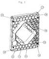
- FIG. 1shows a longitudinal section through an exemplary first Embodiment of the exterior mirror according to the invention for Vehicles.
- the outside mirrorincludes a holder 2- shown in dashed lines - for attaching the mirror to Vehicle, a housing 4 with a housing base 6, which in a housing frame 8 passes, and a cover 10.
- Das Housing 4 or more precisely the housing base 6is on one Carrier plate 12 mounted on its front in a Recording 14 the adjustment unit 16 is arranged.
- a mirror support plate 18is mounted, on the one holding plate 20 for a mirror disk 22 pushed on and with the help of a clamp connection is fixed.
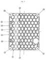
- Fig. 2shows a perspective view of the Carrier plate 12.
- the carrier plate 12comprises a plane Base plate 24 on both sides of a honeycomb structure 26 is integrally formed with the base plate 24.
- the Honeycomb structure 26comprises closely arranged ones hexagonal honeycomb 28 each with six honeycomb walls 30, where two adjacent honeycombs 28 each split the honeycomb wall 30 in between.
- the rectangular one Base plate 24is closed by a in the normal direction of the base plate 24 extending edge wall 32 is completed.
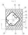
- connection elements 34 for assembly the housing base 6an opening 36 for the electrical Connection of the adjustment unit 16 and the receptacle 14 for the adjustment unit 16 is provided.
- the connection elements 34 and the receptacle 38 for the adjustment unit 16integrally formed in the carrier plate 18.
- Connection elements or bores 42 shown by Screws not shownare enforced to a clamping member, not shown, with the To connect clamping counter bearing 40.
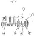
- FIG. 9illustrates different versions of the invention which only in the design of the front edge 57 of the Differentiate housing frame 56.
- Figure 9extends the housing frame 56 is only substantially L-shaped from the housing base 54 away.
- Figure 10is the housing frame 56 at the front edge 57 U-shaped bent backwards and thus offers a picture for the cover 10.
- FIG. 11is the housing frame 56 on the front edge 57 by a Cavity 58 inflated.
Landscapes
- Engineering & Computer Science (AREA)
- Multimedia (AREA)
- Mechanical Engineering (AREA)
- Rear-View Mirror Devices That Are Mounted On The Exterior Of The Vehicle (AREA)
- Laminated Bodies (AREA)
Abstract
Description
Translated fromGermanDie Erfindung betrifft einen Außenspiegel fürFahrzeuge, insbesondere für Nutzfahrzeuge, nach demOberbegriff des Anspruch 1.The invention relates to an exterior mirror forVehicles, especially for commercial vehicles, according to thePreamble of claim 1.
Ein großes Problem bei Außenspiegeln, insbesondere beieinem Nutzfahrzeug, sind die auftretenden Vibrationen, diezum einen den Gebrauch des Spiegels beeinträchtigen und zumanderen zu Ermüdungsbrüchen usw. führen können.A big problem with exterior mirrors, especially witha commercial vehicle, the vibrations that occur areon the one hand impair the use of the mirror and on the othercan lead to fatigue fractures etc.
Ein Lösungsansatz für diese Problematik ist bereits ausder DE-A-4010083 bekannt. Bei der dort gezeigtenSpiegelkonstruktion besitzt das Gehäuse keine tragendeFunktion mehr. Diese wird von einer Trägerplattewahrgenommen, die mittels einer Haltevorrichtung an dem zurBefestigung des Spiegels am Nutzfahrzeug dienenden Halterbefestigt ist. An dieser Trägerplatte sind das Gehäusesowie die mindestens eine Spiegelscheibe des Außenspiegelsund eine Verstelleinheit zu deren Positionseinstellungangebracht. Nachteilig hierbei ist es, daß die Trägerplatteund die Haltevorrichtung getrennte Bauteile sind, wodurchdie Gefahr besteht, daß die stabile Befestigung derTrägerplatte am Halter beeinträchtigt wird. Dies istinsbesondere der Fall, wenn - wie im Ausführungsbeispielder DE-A-4010083 gezeigt - das Gehäuse klemmend zwischender Haltevorrichtung und der Trägerplatte gehalten ist, dasich in diesem Fall Gehäusevibrationen besonders leicht aufdie Trägerplatte übertragen können.A solution to this problem is already outknown from DE-A-4010083. The one shown thereThe housing has no supporting structureFunction more. This is from a carrier plateperceived by means of a holding device on theAttachment of the mirror to the holder serving the commercial vehicleis attached. The housing is on this carrier plateand the at least one mirror pane of the exterior mirrorand an adjustment unit for adjusting their positionappropriate. The disadvantage here is that the carrier plateand the holding device are separate components, wherebythere is a risk that the stable attachment of theCarrier plate on the holder is impaired. This isespecially the case when - as in the embodimentDE-A-4010083 shown - the housing jammed betweenthe holding device and the carrier plate is held therein this case, vibrations in the housing are particularly easycan transfer the carrier plate.
Aus der US-A-4,701,037 ist ferner ein Kraftfahrzeug-Außenspiegelbekannt, bei dem ein zur Karosserie führenderHaltearm und eine daran über ein einstückig angeformtesKlemmlager befestigte Trägerplatte vorgesehen sind. Andieser wird eine Spiegel-Verstelleinheit und daran wiederumeine Spiegelträgerplatte mit einer Spiegelscheibe montiert.From US-A-4,701,037 is also a motor vehicle wing mirrorknown in which a leading to the bodyHolding arm and one attached to it in one pieceClamp bearing attached support plate are provided. Onthis becomes a mirror adjustment unit and in turna mirror support plate with a mirror disc mounted.
Schließlich ist aus der gattungsbildenen EP-A-0 590 510ein Außenspiegel für Nutzfahrzeuge bekannt, der einenHalter zur Befestigung des Spiegels am Fahrzeug, eine ineinem Gehäuse angeordnete Trägerplatte, an der das Gehäusegehalten ist und die mittels einer Haltevorrichtung amHalter befestigt ist, mindestens eine verschwenkbare und ander Trägerplatte angebrachte, im Gehäuse angeordneteSpiegelanordnung mit Spiegelscheibe und mindestens eineVerstelleinheit aufweist, die an der Trägerplatteangebracht ist und die mit der mindestens einenSpiegelanordung zu deren Verschwenkung verbunden ist. Eshat sich herausgestellt, daß auch bei dieserSpiegelkonstruktion die im Einsatz auftretenden Vibrationennoch sehr groß sind. Dies trifft insbesondere für denEinsatz als Außenspiegel von Lastkraftwagen zu.Finally, from generic EP-A-0 590 510an exterior mirror for commercial vehicles known to oneBracket for attaching the mirror to the vehicle, one ina housing arranged carrier plate on which the housingis held and by means of a holding device onHolder is attached to at least one pivotable andthe carrier plate attached, arranged in the housingMirror arrangement with mirror disc and at least oneAdjusting unit has on the support plateis attached and that with the at least oneMirror arrangement is connected to its pivoting. Itit has been found that this tooMirror construction the vibrations occurring in useare still very large. This is especially true for theUse as an exterior mirror for trucks.
Es ist daher Aufgabe der vorliegenden Erfindung einenAußenspiegel für Fahrzeuge, insbesondere für Nutzfahrzeuge,anzugeben, der weniger vibrationsanfällig ist.It is therefore an object of the present inventionOutside mirrors for vehicles, especially for commercial vehicles,specify which is less prone to vibration.
Die Lösung dieser Aufgabe erfolgt durch die Merkmaledes Anspruchs 1.This problem is solved by the featuresof claim 1.
Dadurch, daß die Trägerplatte eine Basisplatteaufweist, bei der wenigstens auf einer Seite einstückig mitder Basisplatte eine Wabenstruktur ausgebildet ist, wirddas Vibrationsverhalten eines Außenspiegels mit einersolchen Trägerplatte entscheidend verbessert.The fact that the carrier plate is a base platehas, in which at least on one side witha honeycomb structure is formed on the base platethe vibration behavior of an outside mirror with asignificantly improved such carrier plate.
Durch die Wabenstruktur, insbesondere auf beiden Seitender Basisplatte, wird zudem auch die Stabilität erhöht, sodaß es möglich wird, anstelle von Metall Kunststoff für dieTrägerplatte zu verwenden, was zu einer Gewichts- undKostenersparnis führt.Due to the honeycomb structure, especially on both sidesthe base plate, the stability is also increased, sothat it becomes possible to use plastic instead of metal for theCarrier plate to use, resulting in a weight andCost savings leads.
Gemäß einer vorteilhaften Ausgestaltung der Erfindungkönnen die insbesondere 6-eckigen Waben inunterschiedlichen Bereichen der Trägerplatteunterschiedlichen Durchmesser aufweisen. Damit kann denunterschiedlichen Belastungen in unterschiedlichenBereichen der Trägerplatte Rechnung getragen werden. Ingleicher Weise ist es auch möglich die Höhe der Wabenwändezu variieren. Durch die Variation der Höhe der Wabenwändekann auch das Klemmgegenlager der als Klemmlagerausgebildeten Haltevorrichtung einstückig mit derTrägerplatte ausgebildet werden.According to an advantageous embodiment of the inventionthe hexagonal honeycombs in particulardifferent areas of the carrier platehave different diameters. So that candifferent loads in differentAreas of the support plate are taken into account. Inin the same way it is also possible the height of the honeycomb wallsto vary. By varying the height of the honeycomb wallscan also use the clamping counter bearing as a clamping bearingtrained holding device in one piece with theCarrier plate are formed.
Gemäß einer weiteren vorteilhaften Ausgestaltung derErfindung ist eine Aufnahme für die Verstelleinheiteinstückig mit der Trägerplatte ausgebildet. Durch dieseAufnahme wird die Verstelleinheit form- und kraftschlüssiggehalten, was ebenfalls erheblich zu einer Verbesserung desVibrationsverhalten führt bzw. eine starke Dämpfung vonVibrationen bewirkt.According to a further advantageous embodiment of theInvention is a holder for the adjustment unitintegrally formed with the carrier plate. Through thisThe adjustment unit becomes positively and non-positivelykept, which also significantly improved theVibration behavior leads or a strong damping ofCauses vibrations.
Gemäß einer weiteren vorteilhaften Ausgestaltung bildetdie Aufnahme ein Teil des Gehäuses der Verstelleinheit.Besonders vorteilhaft ist hierbei bei einer Trägerplatteaus Kunststoff, daß die Verstelleinheit bzw. derenElektronik ohne eigenes Gehäuse in die Aufnahme eingebautwerden kann, da die Isolierung durch die Trägerplatte bzw.die Aufnahme aus Kunststoff übernommen wird.According to a further advantageous embodiment formsthe part of the housing of the adjustment unit.This is particularly advantageous in the case of a carrier platemade of plastic that the adjusting unit or itsElectronics built into the mount without their own housingcan be because the insulation by the carrier plate orthe recording from plastic is taken over.
Gemäß einer weiteren vorteilhaften Ausgestaltung derErfindung sind die Waben auf der Vorderseite gegenüber denWaben auf der Rückseite der Basisplatte gegeneinanderversetzt. Auch hierdurch wird zum einen die Stabilitäterhöht und zum anderen wird das Dämpfungsverhaltenverbessert.According to a further advantageous embodiment of theInvention are the honeycombs on the front opposite theHoneycombs on the back of the base plate against each othertransferred. This also makes stabilityon the other hand, the damping behavior is increasedimproved.
Gemäß einer weiteren vorteilhaften Ausgestaltung derErfindung besitzt die Trägerplatte einstückig angeformte Befestigungselemente zur Befestigung mit einerGehäusebasis, die einen umlaufenden Gehäuserahmen trägt,der den Schwenkbereich der Spiegelscheibe seitlichumgrenzt.According to a further advantageous embodiment of theInvention has the carrier plate integrally moldedFastening elements for fastening with aHousing base, which carries a circumferential housing frame,which laterally swivels the mirror panebounded.
Bei einer alternativen Ausführungsform ist dieBasisplatte der Trägerplatte, die Gehäusebasis und derGehäuserahmen einstückig ausgebildet. Dies vereinfacht dieMontage und zum anderen führt die Zahl der verringertenEinzelteile zu Kostenersparnis und auch zu einerverbesserten Stabilität, was wiederum zu einer verbessertenVibrationsverhalten führt.In an alternative embodiment, theBase plate of the carrier plate, the housing base and theHousing frame formed in one piece. This simplifies theAssembly and on the other hand leads to the number of reducedIndividual parts for cost savings and also oneimproved stability, which in turn leads to improvedVibration behavior leads.
Weitere Einzelheiten, Merkmale und Vorteile derErfindung ergeben sich aus dem nachfolgenden Beschreibungvon beispielhaften Ausführungsformen der Erfindung anhandder Zeichnung.More details, features and advantages of theInvention emerge from the following descriptionof exemplary embodiments of the invention based onthe drawing.
Es zeigt:
- Fig. 1
- einen Längsschnitt durch eine ersteAusführungsform der Erfindung;
- Fig. 2
- eine perspektivische Darstellung einerbeispielhaften Ausführungsform einer Trägerplattemit Wabenstruktur;
- Fig. 3
- eine Aufsicht auf die Rückseite der Trägerplattenach
Figur 2; - Fig. 4
- eine Aufsicht auf die Vorderseite derTrägerplatte nach
Figur 2; - Fig. 5a
- eine Seitenansicht der Trägerplatte nach
Figur 2; - Fig. 5b
- eine weitere Seitenansicht der Trägerplatte nach
Figur 2; - Fig. 6
- eine Schnittdarstellung entlang der Linie A-A in
Figur 4; - Fig. 7
- eine Aufsicht auf eine zweite Ausführungsform derErfindung;
- Fig. 8
- eine Schnittdarstellung entlang der Linie B-B inFigur 7;
- Fig. 9
- eine Schnittdarstellung entlang der Linie A-ANFigur 7;
- Fig. 10
- eine Figur 9 entsprechende Darstellung einerzweiten Version der zweiten Ausführungsform; und
- Fig. 11
- eine Figur 9 entsprechende Darstellung einerdritten Version der zweiten Ausführungsform.
- Fig. 1
- a longitudinal section through a first embodiment of the invention;
- Fig. 2
- a perspective view of an exemplary embodiment of a carrier plate with honeycomb structure;
- Fig. 3
- a top view of the back of the support plate according to Figure 2;
- Fig. 4
- a plan view of the front of the support plate according to Figure 2;
- Fig. 5a
- a side view of the support plate of Figure 2;
- Fig. 5b
- another side view of the support plate according to Figure 2;
- Fig. 6
- a sectional view taken along line AA in Figure 4;
- Fig. 7
- a plan view of a second embodiment of the invention;
- Fig. 8
- a sectional view taken along line BB in Figure 7;
- Fig. 9
- a sectional view along the line A-AN Figure 7;
- Fig. 10
- FIG. 9 shows a representation of a second version of the second embodiment; and
- Fig. 11
- a representation corresponding to Figure 9 of a third version of the second embodiment.
Nachfolgend wird eine erste Ausführungsform derErfindung anhand der Figuren 1 bis 6 beschrieben. Fig. 1zeigt einen Längsschnitt durch eine beispielhafte ersteAusführungsform des erfindungsgemäßen Außenspiegels fürFahrzeuge. Der Außenspiegel umfaßt einen Halter 2 -strichliert dargestellt - zur Befestigung des Spiegels amFahrzeug, ein Gehäuse 4 mit einer Gehäusebasis 6, die ineinem Gehäuserahmen 8 übergeht, und eine Abdeckung 10. DasGehäuse 4 bzw. genauer die Gehäusebasis 6 ist an einerTrägerplatte 12 montiert auf dessen Vorderseite in einerAufnahme 14 die Verstelleinheit 16 angeordnet ist. Auf derVerstelleinheit 16 ist eine Spiegeltragplatte 18 montiert,auf die eine Halteplatte 20 für eine Spiegelscheibe 22aufgeschoben und mit Hilfe einer Klemmschlußverbindungfixiert ist.A first embodiment of theInvention described with reference to Figures 1 to 6. Fig. 1shows a longitudinal section through an exemplary firstEmbodiment of the exterior mirror according to the invention forVehicles. The outside mirror includes a holder 2-shown in dashed lines - for attaching the mirror toVehicle, a
Fig. 2 zeigt eine perspektivische Darstellung derTrägerplatte 12. Die Trägerplatte 12 umfaßt eine ebene Basisplatte 24 auf der beidseitig eine Wabenstruktur 26einstückig mit der Basisplatte 24 ausgebildet ist. DieWabenstruktur 26 umfaßt dicht aneinander angeordnetesechseckige Waben 28 mit jeweils sechs Wabenwänden 30,wobei sich jeweils zwei benachbarte Waben 28 diedazwischenliegende Wabenwand 30 teilen. Die rechteckigeBasisplatte 24 wird durch eine sich in Normalenrichtung zuder Basisplatte 24 erstreckende Randwand 32 abgeschlossen.Fig. 2 shows a perspective view of the
Wie aus den Figuren 2, 3 und 4 zu ersehen ist, sind inder Trägerplatte 18 auch Anschlußelemente 34 zur Montageder Gehäusebasis 6, ein Durchbruch 36 für den elektrischenAnschluß der Verstelleinheit 16 sowie die Aufnahme 14 fürdie Verstelleinheit 16 vorgesehen. Die Anschlußelemente 34und die Aufnahme 38 für die Verstelleinheit 16 sindeinstückig in der Trägerplatte 18 ausgebildet. In Figur 5bund Figur 6 ist auch ein einstückig in die Trägerplatte 18integriertes Klemmenlager 40 dargestellt, in das der Halter2 eingreift. In den Figuren 2 bis 6 sind auchAnschlußelemente bzw. Bohrungen 42 dargestellt, die vonnicht näher dargestellten Schrauben durchsetzt werden, umein nicht näher dargestelltes Klemmglied mit demKlemmgegenlager 40 zu verbinden.As can be seen from FIGS. 2, 3 and 4, inthe
Anhand der Figuren 7 bis 11 wird jetzt eine zweiteAusführungsform der Erfindung mit einer Trägerplatte 50beschrieben, die ebenfalls eine Basisplatte 52 mit einerWabenstruktur 26 auf der Vorder- und Rückseite aufweist. ImUnterschied zu der ersten Ausführungsform gemäß den Figuren1 bis 6 ist jedoch die Basisplatte 52 der Trägerplatte 50einstückig mit einer Gehäusebasis 54 mit Gehäuserand 56ausgebildet. Durch die einstückige Ausbildung vonGehäuserahmen 56, Gehäusebasis 54 und Basisplatte 52 derTrägerplatte 50 verringert sich die Zahl der Einzelteile,so daß die Montage vereinfacht wird. Darüber hinaus istdurch diese Integration eine höhere Stabilität gegeben wasdas Dämpfungs- bzw. Vibrationsverhalten positiv beeinflußt.Based on Figures 7 to 11 is now a secondEmbodiment of the invention with a
In den Schnittdarstellungen der Figuren 9, 10 und 11sind 3 verschiedene Versionen der Erfindung gezeigt, diesich lediglich in der Ausgestaltung der Vorderkante 57 desGehäuserahmens 56 unterscheiden. In Figur 9 erstreckt sichder Gehäuserahmen 56 lediglich im wesentlichen L-förmig vonder Gehäusebasis 54 weg. Bei der Ausführungsform gemäßFigur 10 ist der Gehäuserahmen 56 an der Vorderkante 57 U-förmignach hinten umgebogen und bietet somit eine Aufnahmefür die Abdeckung 10. In der Ausführungsform gemäß Figur 11ist der Gehäuserahmen 56 an der Vorderkante 57 durch einenHohlraum 58 aufgebläht.9, 10 and 113 different versions of the invention are shown whichonly in the design of the
- 22nd
- Halterholder
- 44th
- Gehäusecasing
- 66
- GehäusebasisHousing base
- 88th
- GehäuserahmenHousing frame
- 1010th
- GehäuseabdeckungHousing cover
- 1212th
- TrägerplatteCarrier plate
- 1414
- Aufnahme für VerstelleinheitAdmission for adjustment unit
- 1616
- VerstelleinheitAdjustment unit
- 1818th
- TragplatteSupport plate
- 2020th
- SpiegelhalteplatteMirror mounting plate
- 2222
- SpiegelscheibeMirror disc
- 2424th
- BasisplatteBase plate
- 2626
- WabenstrukturHoneycomb structure
- 2828
- WabenHoneycomb
- 3030th
- WabenwandHoneycomb wall
- 3232
- RandwandEdge wall
- 3434
- AnschlußelementeConnection elements
- 3636
- Durchbruchbreakthrough
- 4040
- KlemmgegenlagerClamping counter bearing
- 4242
- Bohrungen für KlemmvorrichtungBores for clamping device
- 5050
- TrägerplatteCarrier plate
- 5252
- BasisplatteBase plate
- 5454
- GehäusebasisHousing base
- 5656
- GehäuserahmenHousing frame
- 5858
- Hohlraum in 56Cavity in 56th
Claims (12)
Translated fromGermanApplications Claiming Priority (2)
| Application Number | Priority Date | Filing Date | Title |
|---|---|---|---|
| DE19840004 | 1998-09-02 | ||
| DE19840004ADE19840004A1 (en) | 1998-09-02 | 1998-09-02 | Outside mirrors for motor vehicles |
Publications (3)
| Publication Number | Publication Date |
|---|---|
| EP0983900A2true EP0983900A2 (en) | 2000-03-08 |
| EP0983900A3 EP0983900A3 (en) | 2002-04-17 |
| EP0983900B1 EP0983900B1 (en) | 2004-03-24 |
Family
ID=7879575
Family Applications (1)
| Application Number | Title | Priority Date | Filing Date |
|---|---|---|---|
| EP99111670AExpired - LifetimeEP0983900B1 (en) | 1998-09-02 | 1999-06-16 | Exterior vehicle mirror |
Country Status (7)
| Country | Link |
|---|---|
| US (3) | US6520653B1 (en) |
| EP (1) | EP0983900B1 (en) |
| BR (1) | BR9904050A (en) |
| DE (2) | DE19840004A1 (en) |
| ES (1) | ES2216378T3 (en) |
| MX (1) | MXPA99008085A (en) |
| TR (1) | TR199902139A3 (en) |
Cited By (3)
| Publication number | Priority date | Publication date | Assignee | Title |
|---|---|---|---|---|
| EP1199219A1 (en)* | 2000-10-17 | 2002-04-24 | Bühler Motor GmbH | Rear view mirror for vehicles |
| US6483530B2 (en)* | 2000-12-22 | 2002-11-19 | Xerox Corporation | Cast honeycomb structure with integral damping for ROS platform |
| ES2180375A1 (en)* | 2000-05-19 | 2003-02-01 | Fico Mirrors Sa | Attachment device for adjustment mechanisms for vehicle external wing mirrors |
Families Citing this family (7)
| Publication number | Priority date | Publication date | Assignee | Title |
|---|---|---|---|---|
| DE10021743A1 (en)* | 2000-05-04 | 2001-11-15 | Mekra Lang Gmbh & Co Kg | Rear-view mirror arrangement, in particular as an outside mirror for commercial vehicles |
| DE10064647A1 (en) | 2000-12-22 | 2002-07-11 | Mekra Lang Gmbh & Co Kg | Rearview mirror, in particular for motor vehicles |
| US7357522B2 (en) | 2001-03-06 | 2008-04-15 | Lang Mekra North America, Llc | Rearview mirror assembly for motor vehicles |
| JP2006251274A (en)* | 2005-03-10 | 2006-09-21 | Toshiba Corp | Optical scanning apparatus and image forming apparatus |
| DE102008039042B4 (en)* | 2008-08-21 | 2011-04-14 | Schott Ag | Substrate for a mirror carrier with reduced weight and mirror with weight-reduced mirror carrier |
| DE102009005400B4 (en)* | 2009-01-19 | 2011-04-07 | Schott Ag | Substrate for a mirror support, made of glass or glass ceramic |
| DE102013106612A1 (en) | 2013-06-25 | 2015-01-08 | Schott Ag | Tool crown and with the tool crown manufacturable glass ceramic product |
Citations (3)
| Publication number | Priority date | Publication date | Assignee | Title |
|---|---|---|---|---|
| US4701037A (en) | 1986-02-13 | 1987-10-20 | Lacks Industries, Inc. | Remote control rear view mirror, electrically operated |
| DE4010083A1 (en) | 1990-03-29 | 1991-10-02 | Mekra Rangau Plastics | Commercial vehicle external mirror |
| EP0590510A1 (en) | 1992-10-02 | 1994-04-06 | MEKRA Lang GmbH & Co. KG | External rear-view mirror for trucks |
Family Cites Families (43)
| Publication number | Priority date | Publication date | Assignee | Title |
|---|---|---|---|---|
| DE1952584B1 (en)* | 1969-10-18 | 1970-08-06 | Heraeus Schott Quarzschmelze | Lightweight optical mirror made of material containing silicon dioxide |
| US4174823A (en) | 1978-01-23 | 1979-11-20 | Desmo Limited | Motor vehicle rear-view mirrors |
| FR2504075A1 (en) | 1981-04-15 | 1982-10-22 | Hohe Kg | VEHICLE OUTSIDE MIRROR |
| JPS58136536A (en) | 1982-02-08 | 1983-08-13 | Ichikoh Ind Ltd | Electric remote control mirror |
| US4550046A (en)* | 1983-06-20 | 1985-10-29 | Miller Stephen D | Insulating material |
| US4693571A (en) | 1984-01-24 | 1987-09-15 | Kabushiki Kaisha Matsuyama Seisakusho | Support and drive unit for mirror devices |
| DE3669847D1 (en) | 1985-05-14 | 1990-05-03 | Ichikoh Industries Ltd | ELECTRICAL CONTROL DEVICE OF A MIRROR. |
| KR910003533B1 (en) | 1986-08-04 | 1991-06-04 | 가부시키가이샤 도카이리카덴기 세이사쿠쇼 | Exterior mirror assembly of motor vehicle |
| US4877214A (en) | 1987-01-13 | 1989-10-31 | Murakami Kaimeido Co., Ltd. | Holding device of mirror element for rearview mirror |
| IT1208243B (en) | 1987-02-11 | 1989-06-12 | Nardino Righi | REARVIEW MIRROR FOR VEHICLES |
| DE3713579A1 (en) | 1987-04-23 | 1988-11-03 | Bernhard Mittelhaeuser | EXTERNAL REAR VIEW MIRROR FOR MOTOR VEHICLES |
| US4740068A (en) | 1987-04-28 | 1988-04-26 | Magna International Inc. | Rearview mirror assembly with mounting arrangement including integrally molded dual axis pivot means |
| DE3811448A1 (en) | 1987-09-09 | 1989-03-23 | Mekra Rangau Plastics | MOTOR ADJUSTABLE REAR MIRROR |
| JPH0628358Y2 (en) | 1988-04-11 | 1994-08-03 | 株式会社村上開明堂 | rearview mirror |
| EP0342412B1 (en) | 1988-05-20 | 1993-03-24 | MEKRA Rangau Plastics GmbH & Co KG | Motorically adjustable rear view mirror |
| DE8807152U1 (en) | 1988-06-01 | 1988-10-06 | Hohe Kg, 6981 Collenberg | Exterior mirror for a vehicle, in particular for a truck |
| US4915493A (en) | 1989-01-04 | 1990-04-10 | Magna International Inc. | Automotive rear view mirror assembly |
| BR8900142A (en) | 1989-01-10 | 1990-08-14 | Metagal Industria E Comercio Ltda. | IMPROVEMENTS IN EXTERNAL REAR-VIEW MIRROR FOR VEHICLES |
| US4957359A (en) | 1989-04-19 | 1990-09-18 | Navistar International Transportation Corp. | Spring biased mirror assembly with electromagnetic release means |
| EP0486615A4 (en)* | 1989-08-15 | 1992-08-05 | Foster-Miller Inc. | Film-based composite structures for ultralightweight sdi systems |
| US4998814A (en) | 1990-02-12 | 1991-03-12 | Sheller-Globe Corporation | Exterior rearview mirror assembly |
| US5621577A (en) | 1990-03-29 | 1997-04-15 | Mekra Rangau Plastics Gmbh & Co. Kg | External rear-view mirror for commerical vehicles |
| US5151824A (en) | 1990-11-26 | 1992-09-29 | Donnelly Corporation | Vehicular outside mirror assembly |
| JPH04137938U (en) | 1991-06-19 | 1992-12-22 | 株式会社東海理化電機製作所 | vehicle door mirror |
| GB9208831D0 (en) | 1992-04-23 | 1992-06-10 | Britax Wingard Ltd | Exterior rear view mirror for a motor vehicle |
| US5227924A (en) | 1992-10-05 | 1993-07-13 | Delbar Products, Inc. | Horizontally adjustable rearview mirror |
| US5371659A (en) | 1993-02-01 | 1994-12-06 | Donnelly Corporation | Remote-actuated exterior vehicle security light |
| DE4302950A1 (en) | 1993-02-03 | 1994-08-04 | Mekra Rangau Plastics | Adjustable rearview mirror assembly for motor vehicles |
| US5363246A (en) | 1993-05-12 | 1994-11-08 | United Technologies Automotive, Inc. | Power pack for an automotive exterior mirror assembly |
| US5477390A (en) | 1993-08-16 | 1995-12-19 | Lowell Engineering Corp. | Mirror assembly powered into rearwardly folded position against reversing spring bias |
| US5477391A (en) | 1993-08-16 | 1995-12-19 | Lowell Engineering Corp. | Mirror assembly movable into rearwardly folded position with reversing spring bias |
| US5467230A (en) | 1993-08-16 | 1995-11-14 | Lowell Engineering Corp. | Dual pivoted member mount for mirror |
| DE4343691A1 (en) | 1993-12-21 | 1995-06-22 | Mekra Rangau Plastics | Rearview mirror, especially for trucks |
| US5568326A (en) | 1994-10-06 | 1996-10-22 | Ichikoh Industries, Ltd. | Car rearview mirror |
| US5483385A (en) | 1994-10-19 | 1996-01-09 | Lowell Engineering Corp. | Adjustable truck mirror |
| US5889627A (en) | 1996-01-16 | 1999-03-30 | Rosco Inc. | Single shell double view vehicular mirror having manual adjustability and precision hinge plate |
| US5721646A (en) | 1996-02-23 | 1998-02-24 | Kam Truck Components, Inc. | Exterior rearview mirror for vehicles |
| US5687035A (en) | 1996-03-22 | 1997-11-11 | Heinrich Lang | Rear-view mirror assembly having dual motor driven mirrors |
| US5798882A (en) | 1996-03-22 | 1998-08-25 | Sabine Lang | Rear-view mirror assembly with internal antenna mount |
| DE29617413U1 (en) | 1996-10-07 | 1996-11-21 | Mekra Lang Gmbh & Co Kg | Monitoring device for difficult or invisible zones around motor vehicles |
| DE19644824C1 (en) | 1996-10-29 | 1997-12-18 | Buehler Gmbh Nachf Geb | Coupling device for articulated connection of mirror glass support of vehicle rear view mirror with housing of mirror drive |
| US6057025A (en)* | 1998-11-19 | 2000-05-02 | Kalman; Oskar | Complete seamless honeycomb structure and a method for manufacturing thereof |
| US6483530B2 (en)* | 2000-12-22 | 2002-11-19 | Xerox Corporation | Cast honeycomb structure with integral damping for ROS platform |
- 1998
- 1998-09-02DEDE19840004Apatent/DE19840004A1/ennot_activeWithdrawn
- 1999
- 1999-03-12USUS09/266,987patent/US6520653B1/ennot_activeExpired - Lifetime
- 1999-06-16DEDE59908937Tpatent/DE59908937D1/ennot_activeExpired - Fee Related
- 1999-06-16ESES99111670Tpatent/ES2216378T3/ennot_activeExpired - Lifetime
- 1999-06-16EPEP99111670Apatent/EP0983900B1/ennot_activeExpired - Lifetime
- 1999-08-31BRBR9904050-6Apatent/BR9904050A/ennot_activeIP Right Cessation
- 1999-09-02TRTR1999/02139Apatent/TR199902139A3/enunknown
- 1999-09-02MXMXPA99008085Apatent/MXPA99008085A/ennot_activeApplication Discontinuation
- 2002
- 2002-11-15USUS10/295,110patent/US6702449B2/ennot_activeExpired - Fee Related
- 2003
- 2003-08-18USUS10/643,163patent/US6840641B2/ennot_activeExpired - Fee Related
Patent Citations (3)
| Publication number | Priority date | Publication date | Assignee | Title |
|---|---|---|---|---|
| US4701037A (en) | 1986-02-13 | 1987-10-20 | Lacks Industries, Inc. | Remote control rear view mirror, electrically operated |
| DE4010083A1 (en) | 1990-03-29 | 1991-10-02 | Mekra Rangau Plastics | Commercial vehicle external mirror |
| EP0590510A1 (en) | 1992-10-02 | 1994-04-06 | MEKRA Lang GmbH & Co. KG | External rear-view mirror for trucks |
Cited By (4)
| Publication number | Priority date | Publication date | Assignee | Title |
|---|---|---|---|---|
| ES2180375A1 (en)* | 2000-05-19 | 2003-02-01 | Fico Mirrors Sa | Attachment device for adjustment mechanisms for vehicle external wing mirrors |
| ES2180375B1 (en)* | 2000-05-19 | 2004-04-01 | Fico Mirrors, S.A. | FIXING DEVICE FOR REGULATION MECHANISMS FOR EXTERIOR REAR VIEW MACHINES OF MOTOR VEHICLES. |
| EP1199219A1 (en)* | 2000-10-17 | 2002-04-24 | Bühler Motor GmbH | Rear view mirror for vehicles |
| US6483530B2 (en)* | 2000-12-22 | 2002-11-19 | Xerox Corporation | Cast honeycomb structure with integral damping for ROS platform |
Also Published As
| Publication number | Publication date |
|---|---|
| MXPA99008085A (en) | 2003-07-28 |
| ES2216378T3 (en) | 2004-10-16 |
| US20040114263A1 (en) | 2004-06-17 |
| US6520653B1 (en) | 2003-02-18 |
| US6840641B2 (en) | 2005-01-11 |
| TR199902139A2 (en) | 2000-07-21 |
| EP0983900A3 (en) | 2002-04-17 |
| EP0983900B1 (en) | 2004-03-24 |
| DE59908937D1 (en) | 2004-04-29 |
| TR199902139A3 (en) | 2000-07-21 |
| DE19840004A1 (en) | 2000-03-09 |
| US20030067695A1 (en) | 2003-04-10 |
| US6702449B2 (en) | 2004-03-09 |
| BR9904050A (en) | 2000-09-05 |
Similar Documents
| Publication | Publication Date | Title |
|---|---|---|
| DE4413635C2 (en) | Fastening device for a windshield wiper system | |
| DE3903976C2 (en) | Wiper system | |
| EP1216883B1 (en) | Rear-view mirror, especially for vehicles | |
| DE69607732T2 (en) | Modular wiper device | |
| EP0913284A2 (en) | Vehicle door | |
| EP0983900B1 (en) | Exterior vehicle mirror | |
| DE3709069C2 (en) | ||
| DE69307092T2 (en) | Display device | |
| DE60308364T2 (en) | Device for adjusting the side of a window regulator for motor vehicles | |
| EP1640543A1 (en) | Driving device for a displaceable divider element, running gear and divider element | |
| DE4017619C2 (en) | Dimmable interior rear view mirror | |
| DE102004040038B4 (en) | Cluster snap-fastening | |
| EP0580822B1 (en) | Wiper arm, especially for cleaning motor vehicle window panes | |
| EP0991553A1 (en) | Tube plate | |
| DE9308052U1 (en) | Exterior mirrors for commercial vehicles | |
| DE3829466A1 (en) | Wiper arm | |
| DE4317314A1 (en) | Outside mirrors for commercial vehicles | |
| EP1072455A2 (en) | Locking element for releasably lock a vehicle roof to a vehicle body part | |
| DE3148525A1 (en) | Adjustable exterior rearview mirror | |
| WO2004018807A2 (en) | Motor vehicle door lock | |
| DE102016217710A1 (en) | Housing for a drive device and arrangement with a housing | |
| DE3501915A1 (en) | Outside rear view mirror for vehicles, preferably for motor vehicles | |
| EP0226747B1 (en) | Mounting support for an external rear view mirror | |
| DE69916882T2 (en) | MOTOR VEHICLE REAR VIEW MIRROR | |
| DE4436622C2 (en) | Device for damping vibrations of an operating pedal of motor vehicles |
Legal Events
| Date | Code | Title | Description |
|---|---|---|---|
| PUAI | Public reference made under article 153(3) epc to a published international application that has entered the european phase | Free format text:ORIGINAL CODE: 0009012 | |
| AK | Designated contracting states | Kind code of ref document:A2 Designated state(s):AT BE CH CY DE DK ES FI FR GB GR IE IT LI LU MC NL PT SE Kind code of ref document:A2 Designated state(s):DE ES FR GB IT SE | |
| AX | Request for extension of the european patent | Free format text:AL;LT;LV;MK;RO;SI | |
| PUAL | Search report despatched | Free format text:ORIGINAL CODE: 0009013 | |
| AK | Designated contracting states | Kind code of ref document:A3 Designated state(s):AT BE CH CY DE DK ES FI FR GB GR IE IT LI LU MC NL PT SE | |
| AX | Request for extension of the european patent | Free format text:AL;LT;LV;MK;RO;SI | |
| 17P | Request for examination filed | Effective date:20020625 | |
| AKX | Designation fees paid | Free format text:DE ES FR GB IT SE | |
| GRAP | Despatch of communication of intention to grant a patent | Free format text:ORIGINAL CODE: EPIDOSNIGR1 | |
| GRAS | Grant fee paid | Free format text:ORIGINAL CODE: EPIDOSNIGR3 | |
| GRAA | (expected) grant | Free format text:ORIGINAL CODE: 0009210 | |
| AK | Designated contracting states | Kind code of ref document:B1 Designated state(s):DE ES FR GB IT SE | |
| REG | Reference to a national code | Ref country code:GB Ref legal event code:FG4D Free format text:NOT ENGLISH | |
| GBT | Gb: translation of ep patent filed (gb section 77(6)(a)/1977) | Effective date:20040324 | |
| REG | Reference to a national code | Ref country code:IE Ref legal event code:FG4D Free format text:GERMAN | |
| REF | Corresponds to: | Ref document number:59908937 Country of ref document:DE Date of ref document:20040429 Kind code of ref document:P | |
| REG | Reference to a national code | Ref country code:SE Ref legal event code:TRGR | |
| ET | Fr: translation filed | ||
| REG | Reference to a national code | Ref country code:ES Ref legal event code:FG2A Ref document number:2216378 Country of ref document:ES Kind code of ref document:T3 | |
| REG | Reference to a national code | Ref country code:IE Ref legal event code:FD4D | |
| PLBE | No opposition filed within time limit | Free format text:ORIGINAL CODE: 0009261 | |
| STAA | Information on the status of an ep patent application or granted ep patent | Free format text:STATUS: NO OPPOSITION FILED WITHIN TIME LIMIT | |
| 26N | No opposition filed | Effective date:20041228 | |
| PGFP | Annual fee paid to national office [announced via postgrant information from national office to epo] | Ref country code:SE Payment date:20070626 Year of fee payment:9 | |
| EUG | Se: european patent has lapsed | ||
| PGFP | Annual fee paid to national office [announced via postgrant information from national office to epo] | Ref country code:ES Payment date:20090629 Year of fee payment:11 | |
| PGFP | Annual fee paid to national office [announced via postgrant information from national office to epo] | Ref country code:FR Payment date:20090618 Year of fee payment:11 | |
| PGFP | Annual fee paid to national office [announced via postgrant information from national office to epo] | Ref country code:GB Payment date:20090623 Year of fee payment:11 Ref country code:DE Payment date:20090616 Year of fee payment:11 | |
| PGFP | Annual fee paid to national office [announced via postgrant information from national office to epo] | Ref country code:IT Payment date:20090627 Year of fee payment:11 | |
| PG25 | Lapsed in a contracting state [announced via postgrant information from national office to epo] | Ref country code:SE Free format text:LAPSE BECAUSE OF NON-PAYMENT OF DUE FEES Effective date:20080617 | |
| GBPC | Gb: european patent ceased through non-payment of renewal fee | Effective date:20100616 | |
| REG | Reference to a national code | Ref country code:FR Ref legal event code:ST Effective date:20110228 | |
| PG25 | Lapsed in a contracting state [announced via postgrant information from national office to epo] | Ref country code:IT Free format text:LAPSE BECAUSE OF NON-PAYMENT OF DUE FEES Effective date:20100616 | |
| PG25 | Lapsed in a contracting state [announced via postgrant information from national office to epo] | Ref country code:DE Free format text:LAPSE BECAUSE OF NON-PAYMENT OF DUE FEES Effective date:20110101 | |
| PG25 | Lapsed in a contracting state [announced via postgrant information from national office to epo] | Ref country code:FR Free format text:LAPSE BECAUSE OF NON-PAYMENT OF DUE FEES Effective date:20100630 | |
| REG | Reference to a national code | Ref country code:ES Ref legal event code:FD2A Effective date:20110718 | |
| PG25 | Lapsed in a contracting state [announced via postgrant information from national office to epo] | Ref country code:GB Free format text:LAPSE BECAUSE OF NON-PAYMENT OF DUE FEES Effective date:20100616 Ref country code:ES Free format text:LAPSE BECAUSE OF NON-PAYMENT OF DUE FEES Effective date:20110706 | |
| PG25 | Lapsed in a contracting state [announced via postgrant information from national office to epo] | Ref country code:ES Free format text:LAPSE BECAUSE OF NON-PAYMENT OF DUE FEES Effective date:20100617 |