EP0982006A1 - Variable extension combined spinal/epidural needle set and method for its use - Google Patents
Variable extension combined spinal/epidural needle set and method for its useDownload PDFInfo
- Publication number
- EP0982006A1 EP0982006A1EP99305607AEP99305607AEP0982006A1EP 0982006 A1EP0982006 A1EP 0982006A1EP 99305607 AEP99305607 AEP 99305607AEP 99305607 AEP99305607 AEP 99305607AEP 0982006 A1EP0982006 A1EP 0982006A1
- Authority
- EP
- European Patent Office
- Prior art keywords
- needle
- clamp
- hub
- resilient member
- spinal
- Prior art date
- Legal status (The legal status is an assumption and is not a legal conclusion. Google has not performed a legal analysis and makes no representation as to the accuracy of the status listed.)
- Granted
Links
- 238000000034methodMethods0.000titleclaimsdescription22
- 239000012530fluidSubstances0.000claimsabstractdescription31
- 238000004891communicationMethods0.000claimsabstractdescription13
- 239000012858resilient materialSubstances0.000claimsdescription2
- 239000003814drugSubstances0.000description19
- 210000002330subarachnoid spaceAnatomy0.000description13
- 239000012528membraneSubstances0.000description12
- 230000035515penetrationEffects0.000description9
- 239000000463materialSubstances0.000description7
- 241001269524DuraSpecies0.000description5
- 230000000694effectsEffects0.000description4
- 210000001175cerebrospinal fluidAnatomy0.000description3
- 244000005700microbiomeSpecies0.000description3
- 230000001105regulatory effectEffects0.000description3
- 210000001519tissueAnatomy0.000description3
- 206010002091AnaesthesiaDiseases0.000description2
- 206010008164Cerebrospinal fluid leakageDiseases0.000description2
- 229920002943EPDM rubberPolymers0.000description2
- MHAJPDPJQMAIIY-UHFFFAOYSA-NHydrogen peroxideChemical compoundOOMHAJPDPJQMAIIY-UHFFFAOYSA-N0.000description2
- 208000028389Nerve injuryDiseases0.000description2
- 230000037005anaesthesiaEffects0.000description2
- 239000003795chemical substances by applicationSubstances0.000description2
- 239000003193general anesthetic agentSubstances0.000description2
- 239000007788liquidSubstances0.000description2
- 230000008764nerve damageEffects0.000description2
- -1polypropylenePolymers0.000description2
- 230000002980postoperative effectEffects0.000description2
- 239000002904solventSubstances0.000description2
- 238000002693spinal anesthesiaMethods0.000description2
- 230000001225therapeutic effectEffects0.000description2
- 238000003466weldingMethods0.000description2
- IAYPIBMASNFSPL-UHFFFAOYSA-NEthylene oxideChemical compoundC1CO1IAYPIBMASNFSPL-UHFFFAOYSA-N0.000description1
- 206010019233HeadachesDiseases0.000description1
- 244000043261Hevea brasiliensisSpecies0.000description1
- 239000004698PolyethyleneSubstances0.000description1
- 239000004743PolypropyleneSubstances0.000description1
- 239000004793PolystyreneSubstances0.000description1
- FAPWRFPIFSIZLT-UHFFFAOYSA-MSodium chlorideChemical compound[Na+].[Cl-]FAPWRFPIFSIZLT-UHFFFAOYSA-M0.000description1
- 230000002350accommodative effectEffects0.000description1
- 239000000853adhesiveSubstances0.000description1
- 238000004026adhesive bondingMethods0.000description1
- 230000001070adhesive effectEffects0.000description1
- 230000002411adverseEffects0.000description1
- 230000036592analgesiaEffects0.000description1
- 239000003242anti bacterial agentSubstances0.000description1
- 229940088710antibiotic agentDrugs0.000description1
- 229940079593drugDrugs0.000description1
- 239000013536elastomeric materialSubstances0.000description1
- 238000010894electron beam technologyMethods0.000description1
- 239000011888foilSubstances0.000description1
- 231100000869headacheToxicity0.000description1
- 230000005865ionizing radiationEffects0.000description1
- 210000004705lumbosacral regionAnatomy0.000description1
- 239000007769metal materialSubstances0.000description1
- 238000000465mouldingMethods0.000description1
- 229920003052natural elastomerPolymers0.000description1
- 229920001194natural rubberPolymers0.000description1
- 239000004745nonwoven fabricSubstances0.000description1
- 239000000123paperSubstances0.000description1
- 230000000149penetrating effectEffects0.000description1
- 229920000515polycarbonatePolymers0.000description1
- 239000004417polycarbonateSubstances0.000description1
- 229920000573polyethylenePolymers0.000description1
- 229920001155polypropylenePolymers0.000description1
- 229920002223polystyrenePolymers0.000description1
- 238000011176poolingMethods0.000description1
- 238000002360preparation methodMethods0.000description1
- 238000003825pressingMethods0.000description1
- 230000005855radiationEffects0.000description1
- 238000009877renderingMethods0.000description1
- 229920002379silicone rubberPolymers0.000description1
- 229910001220stainless steelInorganic materials0.000description1
- 239000010935stainless steelSubstances0.000description1
- 150000003431steroidsChemical class0.000description1
- 229920003051synthetic elastomerPolymers0.000description1
- 239000005061synthetic rubberSubstances0.000description1
- 229920001169thermoplasticPolymers0.000description1
- 239000012815thermoplastic materialSubstances0.000description1
- 229920005992thermoplastic resinPolymers0.000description1
- 239000004416thermosoftening plasticSubstances0.000description1
- 210000003813thumbAnatomy0.000description1
- 238000009827uniform distributionMethods0.000description1
- 239000012808vapor phaseSubstances0.000description1
Images


Classifications
- A—HUMAN NECESSITIES
- A61—MEDICAL OR VETERINARY SCIENCE; HYGIENE
- A61B—DIAGNOSIS; SURGERY; IDENTIFICATION
- A61B17/00—Surgical instruments, devices or methods
- A61B17/34—Trocars; Puncturing needles
- A61B17/3401—Puncturing needles for the peridural or subarachnoid space or the plexus, e.g. for anaesthesia
- A—HUMAN NECESSITIES
- A61—MEDICAL OR VETERINARY SCIENCE; HYGIENE
- A61B—DIAGNOSIS; SURGERY; IDENTIFICATION
- A61B17/00—Surgical instruments, devices or methods
- A61B17/34—Trocars; Puncturing needles
- A61B2017/347—Locking means, e.g. for locking instrument in cannula
- A—HUMAN NECESSITIES
- A61—MEDICAL OR VETERINARY SCIENCE; HYGIENE
- A61M—DEVICES FOR INTRODUCING MEDIA INTO, OR ONTO, THE BODY; DEVICES FOR TRANSDUCING BODY MEDIA OR FOR TAKING MEDIA FROM THE BODY; DEVICES FOR PRODUCING OR ENDING SLEEP OR STUPOR
- A61M25/00—Catheters; Hollow probes
- A61M2025/0007—Epidural catheters
Definitions
- the present inventionis generally related to the field of hypodermic needles and more specifically to hypodermic needles intended for administration and withdrawal of fluids to the spine of a patient.
- the techniquesboth can be used to create spinal anesthesia, one being delivery of the medicament into the epidural space, "epidural,” and the other, penetration of the dural membrane with delivery of the medicament into the subarachnoid space, "spinal" or “subarachnoid.”
- the medicamentscan be any type of liquid therapeutic material including antibiotics, steroids and the like, but generally are agents used for anesthesia and analgesia.
- the liquid medicamentis an anesthetic agent
- a subarachnoid placementis recognized as providing a faster, more uniform distribution, but several major side effects may result from an improper subarachnoid placement. These side effects may include nerve damage, either from contact with the needle or from high local concentrations of the medicament, pooling or inadequate mixing of the medicament in the cerebrospinal fluid.
- Puncture of the dural membrane for introduction of a needle or catheter with a large gauge needlemay result in postoperative leakage of cerebrospinal fluid from the puncture site, often resulting in severe postoperative headaches.
- puncture of the dural membraneis made with a needle, the smaller the size of the puncture the lower the probability of post-procedural leakage of cerebrospinal fluid.
- Small diameter needles of the length required to enter the subarachnoid spaceare quite flexible and as a result, difficult to accurately position when making penetrations to a depth of several centimeters.
- U.S. Patent 5,085,631discloses a method for placement of a subarachnoid catheter that utilizes a three component apparatus comprising an outer needle, an inner needle and a catheter intermediate the two needles.
- a recent U.S. patent, No. 5,312,375discloses a set for spinal anesthesia that includes a spinal needle, a stylet, an introducer needle through which the spinal needle is introduced and a clamp for fixing the spinal needle for fixing the spinal needle to the introducer needle to stabilize the spinal needle.
- the patentteaches that the tube portion of the introducer needle protrudes proximally beyond the introducer needle hub so that a regulating device with a thumb screw or a toothed member can engage both the introducer needle and the spinal needle to fix the position of the spinal needle relative to the introducer needle.
- the introducer needleis an epidural needle.
- the introducer needlecannot function as a conventional epidural needle. because the fluid path of the epidural needle is not fluid tight to a fluid handling attachment at the hub of the needle.
- U. S. Patent Number 5,584,820discloses a variant of the regulating device disclosed in U.S. 5,312,375 for adjusting the length of a combined spinal epidural needle and the method of practicing its use.
- the disclosed inventionutilizes standard commercially available spinal and epidural needles, adding a fixture for preselecting the spinal needle projection with respect to the epidural needle when the spinal needle is coaxially placed within the epidural needle. While this regulating device and method may be quite useful in the practice of combined spinal epidural medication, the use of this device disclosed in U.S. 5,584,820 adds an additional item to the procedure kit, and additional manipulations. Additionally, neither of these variants teach that the attachment between the spinal needle and the epidural needle forms a fluid tight seal, thus, leakage of medicament or cerebrospinal fluid between the spinal needle and the epidural needle may occur.
- Subarachnoid placement of medicamentsif done properly, is recognized as desirable.
- a device and a method for its usethat would minimize the size of the puncture of the dural membrane, allow accurate and controlled placement of a therapeutically effective amount of a medicament within the subarachnoid space, thereby reducing the potential for nerve damage, coupled with an ability to rapidly initiate and maintain a therapeutic level of the medicament for longer procedures would represent an advance to the medical arts. If such an epidural needle that facilitated the subarachnoid placement that was fully functional as a standard epidural needle the art would be further advanced. A method and apparatus that addresses these needs constitute the present invention.
- An epidural needle of the present inventionincludes a hollow bore therethrough and is useful for releasably fixing a position of a spinal needle disposed within the bore of the epidural needle.
- the epidural needle of the inventionhas an elongate tube defining a longitudinal axis having a proximal end, a distal end and an axial hollow bore having an inside diameter therethrough.
- the needlehas a hub with a proximal end, a distal end and an open passageway having an inside diameter substantially similar to the hollow bore therethrough, the distal end of the hub being fixedly attached to the proximal end of the elongate tube so that the hollow bore of the elongate tube is in fluid communication and substantial axial alignment with the open passageway.
- the hubfurther has a cavity disposed between the proximal end and the distal end of the hub.
- a resilient memberwith an opening therethrough that has an inner diameter substantially similar to the inside diameter of the hollow bore disposed in the cavity so that the opening is substantially axially aligned and in fluid communication with the open passageway.
- the hub of the epidural needle of the inventionhas a clamp with a releasable latch disposed about the resilient member. The clamp is selectively movable between an open position wherein the inner diameter of the resilient member is substantially unaffected, a clamp position wherein the clamp causes a strain to the resilient member and thereby reduces the inner diameter of the opening through the resilient member.
- the clampalso has a latch position where the latch releasably retains the clamp in the clamp position.
- a practitioner using die epidural needle of the invention to position a spinal needle with an outside diameter less than the inside diameter of the hollow tubemay freely axially move the spinal needle within the hollow bore with respect to the epidural needle and fix a position of the spinal needle relative to the epidural needle by the reduction of the inner diameter opening through the resilient member to a diameter less than the outside diameter of the spinal needle by movement of the clamp to the clamp position and the latch position.
- the epidural needle of the inventionis easily manipulated by the practitioner to position the spinal needle. Additionally, the epidural needle of the invention is fully functional as a standard epidural needle since the fluid path from the needle bore to the hub is fluid tight.
- the projection of the spinal needle relative to the epidural needleis substantially infinitely variable within the full range of projection and. once the desired position is achieved, easily fixed by engaging the clamp on the resilient member. Until the clamp is engaged, a practitioner does not need to alter practices used with a standard epidural needle and a standard spinal needle. The engagement of the clamp to fix the position of the spinal needle relative to the epidural needle is facile and substantially intuitive.
- the inventionprovides an advance to the art of delivery of medicaments to the subarachnoid space.
- distal endrefers to the end of the assembly closest to the needle point and the patient
- proximal endrefers to the end of the assembly furthest from the needle point and closest to the practitioner.
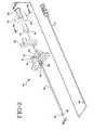
- an epidural needle 10 of the present inventionincludes a hollow bore 12 therethrough and is useful for releasably fixing a position of a spinal needle 14 disposed within bore 12 of the epidural needle.
- Spinal needle 14has a proximal hub 15.
- Epidural needle 10 of the inventionhas an elongate tube 16 defining a longitudinal axis "A" having a proximal end 18, a distal end 20 and axial hollow bore 12 having an inside diameter "b" therethrough.
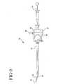
- Needle 10has a hub 22 with a proximal end 24, a distal end 26 and an open passageway 28 having an inside diameter substantially similar to inside diameter "b" of hollow bore 12 therethrough.
- Distal end 26 of hub 22is fixedly attached to proximal end 18 of elongate tube 16 so that hollow bore 12 of elongate tube 16 is in fluid communication and substantial axial alignment with open passageway 28.
- Hub 22further has a cavity 30 disposed between proximal end 24 and distal end 26 of the hub.
- Hub 22 of epidural needle 10 of the inventionhas a clamp 36 with a releasable latch 38 disposed about resilient member 32.
- Clamp 36is selectively movable between an open position, best seen in Fig. 5a, wherein inner diameter "d" of resilient member opening 34 is substantially unaffected, a clamp position, best seen in Fig. 5b, wherein clamp 36 causes a strain to resilient member 32 and thereby reduces the inner diameter of opening 34 through the resilient member.
- Clamp 36also has a latch position, best seen in Fig. 5b, where latch 38 releasably retains clamp 36 in the clamp position.
- a practitioner using epidural needle 10 of the invention to position spinal needle 14 with an outside diameter "e" less than the inside diameter "b" of hollow bore 12may freely axially move spinal needle 14 within the hollow bore with respect to epidural needle 10 and fix a position of a distal point 40 of spinal needle 14 relative to epidural needle 10 by the reduction of inner diameter "d” of opening 34 through resilient member 32 to a diameter "d" less than outside diameter "e” of spinal needle 14 by movement of clamp 36 to the clamp position and the latch position.
- the design of clamp 36is provided to illustrate, but not limit, the invention. Other designs for clamp 36 which cause sufficient strain on resilient member 32 to reduce inside diameter "b” sufficiently to fix the position of the spinal needle may be envisioned and are considered within the scope of the invention.
- hub 22 of the epidural needle and a hub 51 'of stylet 50preferably are shaped to facilitate the practitioner's handling.
- hub 15 of spinal needle 14may also have a similar shape, as shown in Fig. 1, or a more conventional shape as shown in Fig. 2.
- Hub 22also preferably includes wings 53, which preferably are fixedly attached to the hub, but may be removable for particular applications.
- Proximal end 24 of hub 22also includes an attachment for a fluid handling device, preferably a female luer fitting 25.
- hub 22is formed in two portions, a distal portion 19 and a proximal portion 21 that are joined together after placement of resilient member 32 with clamp 36 into cavity 30.
- Distal portion 19 and proximal portion 21may be joined together by snap fit, adhesive bonding, solvent bonding, thermal welding, sonic welding or other techniques for fixedly attaching parts formed from thermoplastic materials.
- the partsare joined by solvent bonding.
- proximal portion 21 and distal portion 19each define part of cavity 30 and each include a recess 33 shaped to form a substantially fluid tight seal about resilient member 30 so that hollow hore 12 of the needle is in substantially fluid tight communication with preferred female luer fitting 25.
- epidural needle 10is fully suitable for any procedure, including, but not limited to, use with a loss of resistance syringe and hanging drop procedure, normally practiced with standard epidural needless in addition to the disclosed ability to fix the position of a spinal needle with respect to the epidural needle. This versatility, of use is not possible with previous variable extension spinal/epidural devices.
- epidural needle 10is part of a kit 11 that includes spinal needle 14 and a stylet 50 to occlude hollow bore 12 of the epidural needle and placed in a package 52, illustrated in phantom in Fig. 1.
- Kit 11may also include a stylet 17 for spinal needle 14.
- Kit 11may also include other items (not shown) in addition to spinal needle 14 and stylet 17, such as gloves, skin preparation materials, medicaments and the like for particular applications.
- Package 52is preferably formed from materials substantially resistant to microorganisms, sealed and exposed to conditions suitable to render any microorganisms therein non-viable.
- Suitable materials for forming package 52include but are not limited to thermoplastic films, metallic foils, paper, non-wovens as well as combinations of these materials.
- Suitable conditions for rendering microorganisms non-viableinclude, but are not limited to, exposure to gaseous agents such as ethylene oxide, vapor phase hydrogen peroxide and the like, and exposure to ionizing radiation such as is generated by electron beam. ultraviolet or gamma radiation
- Resilient member 32is preferably formed from a resilient elastomeric material. Suitable elastomeric materials include. but are not limited to natural rubber, synthetic rubber, silicone elastomer, ethylene propylene diene monomer (EPDM) and the like. Preferably. a resilient material is selected with a Shore A durometer between about 30 and 80 to be formed into resilient member 32. In these figures resilient member 32 is shown as a cylinder, other elongate shapes also are considered within the scope of the disclosure and may be selected for particular applications.
- Suitable materials for forming hub 22include, but are not limited to. thermoplastic resins such as polypropylene. polyethylene, polycarbonate, polystyrene and the like.
- thermoplastic resinssuch as polypropylene. polyethylene, polycarbonate, polystyrene and the like.
- elongate tube 16is fixedly attached to hub 22 by an adhesive bond.
- adhesive bondbut other known methods of bonding including, but not limited to. insert molding and the like may be used for particular applications.
- distal point 20 of epidural needle 10is formed into a sharpened point suitable for penetrating a patient's tissue.
- a method for a practitioner to use epidural needle 10 to position spinal needle 12 in the subarachnoid space 60includes positioning epidural needle 10 in the lumbar region 64 of spine 62 between the vertebrae 66 so that distal point 20 of the epidural needle is in close proximity to the dural membrane 70.
- epidural needle bore 12is occluded by stylet 50 during the penetration of the needle through the patient's tissue so that no tissue core is cut, forced into bore 12 and possibly introduced into the patient's spine by the instillation of the medicament.
- the practitionerwithdraws stylet 50 from bore 12 and then may attach a "loss of resistance" syringe containing normal saline solution or air. The practitioner then advances epidural needle 10 while applying pressure to the syringe plunger. Upon penetration into the epidural space, the practitioner perceives a "loss of resistance” to movement of the syringe plunger and the syringe contents are delivered into the now created epidural space. Following this, the practitioner removes the "loss of resistance" syringe and introduces spinal needle 14 into bore 12.
- Epidural needle 10 of the inventionby having resilient member 32 form a substantially air and fluid tight seal between bore 12 of the needle and attachment 24 for a fluid handling device, allows the practitioner to use epidural needle 10 as a conventional needle for performing the "loss of resistance test".
- Earlier variable extension needlessuch as disclosed in U.S. Patent No. 5,584,820 do not allow such use. because there is no fluid tight seal between the bore of the needle and a fluid attachment.
- the practitionerpreferably leaves clamp 36 in the open position to allow slidable movement of spinal needle 14 through bore 12.
- Spinal needle 14preferably has indicia 15 to indicate the position of distal point 40 of the spinal needle is relative to distal point 20 of the epidural needle.
- the practitioneradvances epidural needle point 20 to close proximity to the dural membrane 70 and advances the spinal needle until the distal point 40 penetrates the dural membrane and enters subarachnoid space 60.
- the practitionerthen may move clamp 36 to the clamp position and engage latch 38 to fix the position of the spinal needle relative to the epidural needle with a projection distance "X".
- latch 38 of clamp 36is selectively engageable and releasably by the practitioner to accommodate the practitioner's needs during the procedure.
- Spinal needle 14may also include a removable stylet 17 to occlude the bore of the spinal needle until the practitioner has completed the placement of spinal needle 14. Once placement of spinal needle 14 in the subarachnoid space is achieved and confirmed, the practitioner then may attach a fluid handling device such as a syringe to the spinal needle and instill the medicament into the subarachnoid space.
- a fluid handling devicesuch as a syringe
- the table belowrelates standard needle gauge sizes to the inner and outer diameter of hypodermic tubing used for forming the needles described above.
- the preferred needle set of the inventionincludes a twenty-five gauge spinal needle 14 slidably fit within a seventeen gauge epidural needle 10.
- a combination of a twenty-seven gauge spinal needle 14 and an eighteen gauge epidural needle 10, a twenty-seven gauge spinal needle 14 and a seventeen gauge epidural needle 10 or a twenty-nine gauge spinal needle 14 and an eighteen gauge epidural needle 10 or other similar combinationsmay be preferred for particular applications and are considered within the scope of the invention.
- the larger number gauge size (smaller outside diameters) combinationsare often preferred for patients of smaller stature or for pediatric applications.
- Spinal needles 14 having gauge sizes between about twenty-two gauge and twenty-nine gaugeare preferred by most practitioners for most applications.
- Useful needle length ranges accommodative of most patient staturesinclude epidural needle 10 having an effective penetration length between about 8 cm to about 9 cm and spinal needle 14 having a sufficient length so that projection distance ("X") of spinal needle point 40 beyond epidural needle point 20 when the spinal needle is fully seated in epidural needle 10 is between about 14.5 mm to about 15.5 mm.
- Xprojection distance
- other lengths of both the spinal and epidural needlesmay be preferred.
- consideration of a number of factors including, but not limited to, the desired spinal needle projection ("X") range and the patient stature rangeshould be considered when selecting design parameters including, but not limited to, gauge sizes, needle lengths and the particular configuration of the projection adjustment mechanism for the invention. Numerous other combinations of these design parameters beyond those described in this disclosure may be envisioned and are considered to be within the scope of the invention.
- Epidural needle 10provides practitioners an improvement in their ability to deliver medicaments to the subarachnoid space. Since epidural needle 10 provides a fluid tight and unrestricted path between bore 12 and attachment 24 as long as clamp 36 is not engaged, the epidural needle of the invention is suitable for any normal procedure that may be desired by the practitioner. The epidural needle of the invention then provides the practitioner to fix the position of the spinal needle with respect to the epidural needle.
- the epidural needle of the invention in combination with a standard spinal needle or a preferred spinal needle having a hub shape similar to the preferred shape of the epidural needle hubis easy to use and allows the practitioner more control of the penetration of the dural membrane than currently available needle sets. By providing the practitioner with more control, the needle set of the invention substantially reduces the chance of adverse effects on the patient receiving the treatment.
Landscapes
- Health & Medical Sciences (AREA)
- Surgery (AREA)
- Life Sciences & Earth Sciences (AREA)
- Heart & Thoracic Surgery (AREA)
- Molecular Biology (AREA)
- Pathology (AREA)
- Engineering & Computer Science (AREA)
- Biomedical Technology (AREA)
- Anesthesiology (AREA)
- Medical Informatics (AREA)
- Nuclear Medicine, Radiotherapy & Molecular Imaging (AREA)
- Animal Behavior & Ethology (AREA)
- General Health & Medical Sciences (AREA)
- Public Health (AREA)
- Veterinary Medicine (AREA)
- Media Introduction/Drainage Providing Device (AREA)
- Infusion, Injection, And Reservoir Apparatuses (AREA)
Abstract
Description
| Table of Hypodermic Tubing Nominal Sizes | ||
| Gauge | Outside Diameter (mm) | Inside Diameter (mm) |
| 30 | 0.30 | 0.18 |
| 29 | 0.33 | 0.20 |
| 28 | 0.36 | 0.20 |
| 27 | 0.40 | 0.25 |
| 26 | 0.46 | 0.30 |
| 25 | 0.51 | 0.30 |
| 24 | 0.56 | 0.36 |
| 23 | 0.64 | 0.38 |
| 22 | 0.71 | 0.46 |
| 21 | 0.82 | 0.56 |
| 20 | 0.90 | 0.65 |
| 19 | 1.08 | 0.80 |
| 18 | 1.27 | 0.96 |
| 17 | 1.50 | 1.17 |
| 16 | 1.65 | 1.32 |
Claims (10)
- An epidural needle having a hollow bore therethrough useful for releasably fixinga position of a spinal needle disposed within the bore of the epidural needle comprises:an elongate tube defining a longitudinal axis having a proximal end, a distal end and anaxial hollow bore having an inside diameter therethrough;a hub having a proximal end, a distal end and an open passageway having an insidediameter substantially similar to said hollow bore therethrough, said distal end of said hub beingfixedly attached to said proximal end of said elongate tube so that said hollow bore of saidelongate tube is in fluid communication and substantial axial alignment with said openpassageway, said hub further having a cavity therein disposed between said proximal end andsaid distal end of said hub;a resilient member having an opening therethrough with an inner diameter, substantiallysimilar to said inside diameter of said hollow bore, said resilient member disposed in said cavityso that said opening is substantially axially aligned and in fluid communication with said openpassageway; anda clamp having a releasable latch disposed about said resilient member, said clamp beingselectively movable between an open position wherein said inner diameter of said resilientmember is substantially unaffected, a clamp position wherein said clamp causes a strain to atleast a portion of said resilient member thereby reducing said inner diameter of said openingthrough at least a portion of said resilient member, and a latch position wherein said latchreleasably retains said clamp in said clamp position; and wherein a practitioner using said epidural needle to position a spinal needle having an outside diameter less than said insidediameter of said hollow tube may freely axially move the spinal needle within said hollow borewith respect to said epidural needle and fix a position of the spinal needle relative to saidepidural needle by said reduction of said inner diameter of said opening through said resilientmember to a diameter less than the outside diameter of the spinal needle by movement of saidclamp to said clamp position and said latch position thereby to grasp releasably the spinal needlesufficiently to fix the relative position of the spinal needle.
- The epidural needle of Claim 1 wherein said at least a portion of said clampprojects outwardly from said hub to facilitate the practitioner's selective movement of said clampbetween said open position, said clamp position and said latch position.
- The epidural needle of Claim 2 wherein said portion of said clamp that projectsoutwardly from said hub is sized and shaped to allow the practitioner to apply digital pressure forsaid selective movement of said clamp between said open position, said clamp position and saidlatch position.
- The epidural needle of Claim 3 wherein said portion of said clamp that projectsoutwardly from said hub further includes said releasable latch for selectively retaining saidclamp in said clamp position.
- The epidural needle of Claim 1 wherein said hub further includes at least oneoutwardly projecting wing substantially transverse to said axis, said at least one wing beinguseful to facilitate the practitioner's placement of said epidural needle.
- The epidural needle of Claim 1 wherein said resilient material has a Shore Adurometer between about 30 and about 80 and said resilient member forms a substantially air andfluid tight seal between said epidural needle hub and an outside surface of said spinal needlewhen said clamp is positioned in said clamp position and said latch position.
- A method for releasably fixing a position of a spinal needle disposed within thebore of an epidural needle comprises:providing an epidural needle including an elongate tube defining a longitudinal axis, saidtube having a proximal end, a distal end and an axial hollow bore having an inside diametertherethrough, a hub having a proximal end, a distal end and an open passageway having an insidediameter substantially similar to said hollow bore therethrough, said distal end of said hub beingfixedly attached to said proximal end of said elongate tube so that said hollow bore of saidelongate tube is in fluid communication and substantial axial alignment with said openpassageway and wherein said open hub further having a cavity disposed between said proximalend and said distal end of said hub, a resilient member having an opening therethrough with aninner diameter, substantially similar to said inside diameter of said hollow bore, said resilientmember disposed in said cavity so that said opening is substantially axially aligned and in fluidcommunication with said open passageway, and a clamp having a releasable latch disposed aboutsaid resilient member, said clamp being selectively movable between an open position whereinsaid inner diameter of said resilient member is substantially unaffected, a clamp position whereinsaid clamp causes a strain to said resilient member thereby reducing said inner diameter of saidopening through said resilient member, and a latch position wherein said latch releasably retainssaid clamp in said clamp position;placing a spinal needle having an outside diameter less than said inside diameter ofwithin said hollow bore of said epidural needle;selecting a position of said spinal needle relative to said epidural needle; andfixing a position of said spinal needle relative to said epidural needle by moving of saidclamp to said clamp position and said latch position thereby releasably fixing said position ofsaid spinal needle relative to said epidural needle.
- A combined spinal epidural needle set comprises:an epidural needle including an elongate tube defining a longitudinal axis having aproximal end, a distal end and an axial hollow bore having an inside diameter therethrough, saidepidural needle having a hub having a proximal end, a distal end and an open passageway havingan inside diameter substantially similar to said hollow bore therethrough, said distal end of saidhub being fixedly attached to said proximal end of said elongate tube so that said hollow bore ofsaid elongate tube is in fluid communication and substantial axial alignment with said openpassageway and wherein said hub further having a cavity disposed between said proximal endand said distal end of said hub, a resilient member having an opening therethrough with an innerdiameter, substantially similar to said inside diameter of said hollow bore, said resilient memberdisposed in said cavity so that said opening is substantially axially aligned and in fluidcommunication with said open passageway, and a clamp having a releasable latch disposed aboutsaid resilient member, said clamp being selectively movable between an open position whereinsaid inner diameter of said resilient member is substantially unaffected, a clamp position whereinsaid clamp causes a strain to said resilient member thereby reducing said inner diameter of saidopening through said resilient member, and a latch position wherein said latch releasably retainssaid clamp in said clamp position; anda spinal needle having an outside diameter less than said inside diameter of said hollowtube disposed within said hollow bore, and wherein a practitioner using said epidural needle toposition said spinal needle may freely axially move said spinal needle within said hollow borewith respect to said epidural needle and fix a position of said spinal needle relative to saidepidural needle by said reduction of said inner diameter opening through said resilient member toa diameter less than said outside diameter of the spinal needle by movement of said clamp to saidclamp position and said latch position thereby to grasp releasably the spinal needle sufficiently tofix the position.
- The combined spinal epidural needle set of claim 8 further comprising a styletsized and shaped to fit removably within and substantially occlude said hollow bore of saidepidural needle.
- The combined spinal epidural needle set of claim 8 further comprising a styletsized and shaped to fit removably within and substantially occlude a bore of said spinal needleand each of said hub of said epidural needle, a hub of said spinal needle, a hub of said epiduralneedle stylet and a hub of said spinal needle stylet have a size and shape and are disposed to beengaged with one another to facilitate a practitioner's manipulation of said set during aprocedure.
Applications Claiming Priority (2)
| Application Number | Priority Date | Filing Date | Title |
|---|---|---|---|
| US118269 | 1998-07-17 | ||
| US09/118,269US6245044B1 (en) | 1998-07-17 | 1998-07-17 | Variable extension combined spinal/epidural needle set and method for its use |
Publications (2)
| Publication Number | Publication Date |
|---|---|
| EP0982006A1true EP0982006A1 (en) | 2000-03-01 |
| EP0982006B1 EP0982006B1 (en) | 2005-12-07 |
Family
ID=22377548
Family Applications (1)
| Application Number | Title | Priority Date | Filing Date |
|---|---|---|---|
| EP99305607AExpired - LifetimeEP0982006B1 (en) | 1998-07-17 | 1999-07-15 | Variable extension combined spinal/epidural needle set |
Country Status (5)
| Country | Link |
|---|---|
| US (1) | US6245044B1 (en) |
| EP (1) | EP0982006B1 (en) |
| CA (1) | CA2277245A1 (en) |
| DE (1) | DE69928731T2 (en) |
| ES (1) | ES2255229T3 (en) |
Cited By (2)
| Publication number | Priority date | Publication date | Assignee | Title |
|---|---|---|---|---|
| WO2002078551A1 (en)* | 2001-03-30 | 2002-10-10 | Becton, Dickinson And Company | Variable extension combined spinal/epidural needle set and method for its use |
| US8528426B2 (en) | 2008-09-23 | 2013-09-10 | Noble House Group Pty. Ltd. | Device for transfer of body fluids |
Families Citing this family (97)
| Publication number | Priority date | Publication date | Assignee | Title |
|---|---|---|---|---|
| IL114960A0 (en) | 1995-03-20 | 1995-12-08 | Medimop Medical Projects Ltd | Flow control device |
| US20040015133A1 (en)* | 2000-05-31 | 2004-01-22 | Hussain Karim | Epidural apparatus |
| US6641563B1 (en)* | 2000-11-01 | 2003-11-04 | Arrow International, Inc. | Stylet-free epidural catheter and thread assist device |
| US6558353B2 (en)* | 2001-01-25 | 2003-05-06 | Walter A. Zohmann | Spinal needle |
| US20070083184A1 (en)* | 2001-11-20 | 2007-04-12 | Simpson Robert C | Epidural catheter system and methods of use |
| US7044936B2 (en) | 2002-08-21 | 2006-05-16 | Arrow International Inc. | Catheter connector with pivot lever spring latch |
| GB0301934D0 (en)* | 2003-01-28 | 2003-02-26 | Sundar Satish | Delivery apparatus and location method |
| US8333734B2 (en)* | 2003-07-03 | 2012-12-18 | Walter A. Zohmann | Fenestrated peripheral nerve block needle and method for using the same |
| US20050090801A1 (en)* | 2003-10-27 | 2005-04-28 | Racz N. S. | Safety spinal catheter |
| IL161660A0 (en) | 2004-04-29 | 2004-09-27 | Medimop Medical Projects Ltd | Liquid drug delivery device |
| US8070739B2 (en) | 2005-08-11 | 2011-12-06 | Medimop Medical Projects Ltd. | Liquid drug transfer devices for failsafe correct snap fitting onto medicinal vials |
| US20070282300A1 (en) | 2006-06-05 | 2007-12-06 | Mohamed Attawia | Intervertebral Disc Puncture and Treatment System |
| USD596742S1 (en)* | 2006-06-07 | 2009-07-21 | Medical Device Innovations Ltd. | Surgical instrument for hypertension pneumothorax |
| US9888940B2 (en) | 2006-09-11 | 2018-02-13 | Custom Medical Applications | Neural injection system and related methods |
| US20080065029A1 (en)* | 2006-09-11 | 2008-03-13 | Racz N S | Nerve block needle and related methods |
| US20080312637A1 (en)* | 2007-06-15 | 2008-12-18 | Kyphon Inc. | Device and Methods for Introducing a Catheter into an Intervertebral Disc |
| US7922696B2 (en) | 2007-01-24 | 2011-04-12 | Access Scientific, Inc. | Access device |
| US8414587B2 (en) | 2007-01-26 | 2013-04-09 | Laurimed, Llc | Styli used to position device for carrying out selective discetomy |
| US8088119B2 (en)* | 2007-02-01 | 2012-01-03 | Laurimed, Llc | Methods and devices for treating tissue |
| IL182605A0 (en) | 2007-04-17 | 2007-07-24 | Medimop Medical Projects Ltd | Fluid control device with manually depressed actuator |
| EP3093038B1 (en) | 2007-04-18 | 2019-05-22 | Access Scientific, Inc. | Access device |
| WO2008157376A1 (en)* | 2007-06-13 | 2008-12-24 | Epimed International Inc. | Safety neural injection system and related methods |
| US8226619B2 (en)* | 2007-06-15 | 2012-07-24 | Kyphon Sarl | Systems and methods for needle access to an intervertebral disc |
| EP2190518B1 (en) | 2007-09-18 | 2016-01-27 | Medimop Medical Projects Ltd. | Medicament mixing and injection apparatus |
| IL186290A0 (en) | 2007-09-25 | 2008-01-20 | Medimop Medical Projects Ltd | Liquid drug delivery devices for use with syringe having widened distal tip |
| US9067013B2 (en)* | 2007-10-24 | 2015-06-30 | C. R. Bard, Inc. | Medical article securement device |
| NZ586548A (en)* | 2008-01-14 | 2012-07-27 | Custom Med Applications Inc | Flexible spinal needle assembly with an internal flow element configured to avoid kinking or restriction of the needle |
| US8287496B2 (en)* | 2008-01-17 | 2012-10-16 | Custom Medical Applications, Inc. | Flow elements for use with flexible spinal needles, needle assemblies and methods therefor |
| WO2009124192A1 (en) | 2008-04-02 | 2009-10-08 | Laurimed, Llc | Methods and devices for delivering injections |
| USD641080S1 (en) | 2009-03-31 | 2011-07-05 | Medimop Medical Projects Ltd. | Medical device having syringe port with locking mechanism |
| USD630732S1 (en) | 2009-09-29 | 2011-01-11 | Medimop Medical Projects Ltd. | Vial adapter with female connector |
| IL201323A0 (en) | 2009-10-01 | 2010-05-31 | Medimop Medical Projects Ltd | Fluid transfer device for assembling a vial with pre-attached female connector |
| IL202069A0 (en) | 2009-11-12 | 2010-06-16 | Medimop Medical Projects Ltd | Fluid transfer device with sealing arrangement |
| IL202070A0 (en) | 2009-11-12 | 2010-06-16 | Medimop Medical Projects Ltd | Inline liquid drug medical device |
| AU2011213558A1 (en) | 2010-02-08 | 2012-09-27 | Access Scientific, Inc. | Access device |
| DK2512399T3 (en) | 2010-02-24 | 2015-06-22 | Medimop Medical Projects Ltd | Fluid transfer device with vent arrangement |
| DK2512398T3 (en) | 2010-02-24 | 2014-10-13 | Medimop Medical Projects Ltd | Liquid drug transfer device with vented ampoule adapter |
| CN103068327B (en) | 2010-06-30 | 2015-08-05 | 劳瑞弥徳有限责任公司 | For excising and withdraw from the apparatus and method of tissue |
| US8685052B2 (en) | 2010-06-30 | 2014-04-01 | Laurimed, Llc | Devices and methods for cutting tissue |
| USD669980S1 (en) | 2010-10-15 | 2012-10-30 | Medimop Medical Projects Ltd. | Vented vial adapter |
| IL209290A0 (en) | 2010-11-14 | 2011-01-31 | Medimop Medical Projects Ltd | Inline liquid drug medical device having rotary flow control member |
| WO2012135761A1 (en)* | 2011-04-01 | 2012-10-04 | Access Scientific, Inc. | Access device |
| IL212420A0 (en) | 2011-04-17 | 2011-06-30 | Medimop Medical Projects Ltd | Liquid drug transfer assembly |
| IL215699A0 (en) | 2011-10-11 | 2011-12-29 | Medimop Medical Projects Ltd | Liquid drug reconstitution assemblage for use with iv bag and drug vial |
| WO2013119336A1 (en) | 2012-02-10 | 2013-08-15 | Laurimed, Llc | Vacuum powered rotary devices and methods |
| USD720451S1 (en) | 2012-02-13 | 2014-12-30 | Medimop Medical Projects Ltd. | Liquid drug transfer assembly |
| USD674088S1 (en) | 2012-02-13 | 2013-01-08 | Medimop Medical Projects Ltd. | Vial adapter |
| USD737436S1 (en) | 2012-02-13 | 2015-08-25 | Medimop Medical Projects Ltd. | Liquid drug reconstitution assembly |
| IL219065A0 (en) | 2012-04-05 | 2012-07-31 | Medimop Medical Projects Ltd | Fluid transfer device with manual operated cartridge release arrangement |
| IL221635A0 (en) | 2012-08-26 | 2012-12-31 | Medimop Medical Projects Ltd | Drug vial mixing and transfer device for use with iv bag and drug vial |
| IL221634A0 (en) | 2012-08-26 | 2012-12-31 | Medimop Medical Projects Ltd | Universal drug vial adapter |
| DK2872100T3 (en) | 2012-09-13 | 2017-07-10 | Medimop Medical Projects Ltd | Telescopic female adapter for drug ampoule |
| USD734868S1 (en) | 2012-11-27 | 2015-07-21 | Medimop Medical Projects Ltd. | Drug vial adapter with downwardly depending stopper |
| EP2740422A1 (en) | 2012-12-05 | 2014-06-11 | Custom Medical Applications | Safety neural injection system and related methods |
| USD748774S1 (en)* | 2012-12-26 | 2016-02-02 | Angiodynamics, Inc | Introducer hub |
| JP2014180571A (en) | 2013-03-15 | 2014-09-29 | Custom Medical Applications | Safety neural injection system and related method |
| US9566087B2 (en) | 2013-03-15 | 2017-02-14 | Access Scientific, Llc | Vascular access device |
| IL225734A0 (en) | 2013-04-14 | 2013-09-30 | Medimop Medical Projects Ltd | Ready-to-use drug vial assemblages including drug vial and drug vial closure having fluid transfer member, and drug vial closure therefor |
| CN105228676B (en) | 2013-05-10 | 2018-01-05 | 麦迪麦珀医疗工程有限公司 | Include the medical treatment device of the vial adapter with inline dry kit |
| USD767124S1 (en) | 2013-08-07 | 2016-09-20 | Medimop Medical Projects Ltd. | Liquid transfer device with integral vial adapter |
| DE212014000169U1 (en) | 2013-08-07 | 2016-03-14 | Medimop Medical Projects Ltd. | Fluid transfer devices for use with infusion fluid containers |
| USD765837S1 (en) | 2013-08-07 | 2016-09-06 | Medimop Medical Projects Ltd. | Liquid transfer device with integral vial adapter |
| AR098613A1 (en) | 2013-12-06 | 2016-06-01 | Genentech Inc | APPLIANCES AND METHODS FOR THE ADMINISTRATION OF MEDICINES IN LOW VOLUMES |
| US8815099B1 (en) | 2014-01-21 | 2014-08-26 | Laurimed, Llc | Devices and methods for filtering and/or collecting tissue |
| USD757933S1 (en) | 2014-09-11 | 2016-05-31 | Medimop Medical Projects Ltd. | Dual vial adapter assemblage |
| JP6358724B2 (en) | 2015-01-05 | 2018-07-18 | ウエスト・ファーマ.サービシーズ・イスラエル,リミテッド | Dual vial adapter assembly with easy removable pill adapter to ensure accurate use |
| USD775325S1 (en)* | 2015-03-12 | 2016-12-27 | Genzyme Corporation | Plunger and finger grip for a syringe |
| USD775324S1 (en)* | 2015-03-12 | 2016-12-27 | Genzyme Corporation | Plunger and finger grip for a syringe |
| US11027099B2 (en) | 2015-04-30 | 2021-06-08 | Smiths Medical Asd, Inc. | Vascular access device |
| WO2017009822A1 (en) | 2015-07-16 | 2017-01-19 | Medimop Medical Projects Ltd | Liquid drug transfer devices for secure telescopic snap fit on injection vials |
| USD801522S1 (en) | 2015-11-09 | 2017-10-31 | Medimop Medical Projects Ltd. | Fluid transfer assembly |
| CN115721558A (en) | 2015-11-25 | 2023-03-03 | 西部制药服务以色列有限公司 | Dual vial adapter assembly comprising a drug vial adapter having a self-sealing inlet valve |
| USD818576S1 (en)* | 2016-05-19 | 2018-05-22 | Mel-Mont Medical, Llc | Finger grip for vaginal/cervical cell collecting tool |
| IL245800A0 (en) | 2016-05-24 | 2016-08-31 | West Pharma Services Il Ltd | Dual vial adapter assemblages including identical twin vial adapters |
| IL245803A0 (en) | 2016-05-24 | 2016-08-31 | West Pharma Services Il Ltd | Dual vial adapter assemblages including vented drug vial adapter and vented liquid vial adapter |
| USD818577S1 (en)* | 2016-05-31 | 2018-05-22 | Mel-Mont Medical, Llc | Vaginal/cervical cell collecting tool |
| IL246073A0 (en) | 2016-06-06 | 2016-08-31 | West Pharma Services Il Ltd | Fluid transfer devices for use with drug pump cartridge having slidable driving plunger |
| IL247376A0 (en) | 2016-08-21 | 2016-12-29 | Medimop Medical Projects Ltd | Syringe assembly |
| WO2018053148A1 (en)* | 2016-09-14 | 2018-03-22 | Boston Scientific Scimed, Inc | Catheter hubs |
| USD832430S1 (en) | 2016-11-15 | 2018-10-30 | West Pharma. Services IL, Ltd. | Dual vial adapter assemblage |
| IL249408A0 (en) | 2016-12-06 | 2017-03-30 | Medimop Medical Projects Ltd | Liquid transfer device for use with infusion liquid container and pincers-like hand tool for use therewith for releasing intact drug vial therefrom |
| IL251458A0 (en) | 2017-03-29 | 2017-06-29 | Medimop Medical Projects Ltd | User actuated liquid drug transfer devices for use in ready-to-use (rtu) liquid drug transfer assemblages |
| CN107049442B (en)* | 2017-06-03 | 2023-05-26 | 成都五义医疗科技有限公司 | Puncture needle comprising diameter adaption device and application method thereof |
| CN107049380B (en)* | 2017-06-03 | 2023-05-26 | 成都五义医疗科技有限公司 | Standardized puncture outfit series products and use method thereof |
| IL254802A0 (en) | 2017-09-29 | 2017-12-31 | Medimop Medical Projects Ltd | Dual vial adapter assemblages with twin vented female vial adapters |
| US10569059B2 (en) | 2018-03-01 | 2020-02-25 | Asspv, Llc | Guidewire retention device |
| JP1630477S (en) | 2018-07-06 | 2019-05-07 | ||
| USD923812S1 (en) | 2019-01-16 | 2021-06-29 | West Pharma. Services IL, Ltd. | Medication mixing apparatus |
| JP1648075S (en) | 2019-01-17 | 2019-12-16 | ||
| JP7209849B2 (en) | 2019-01-18 | 2023-01-20 | ウェスト・ファーマ・サービシーズ・アイエル・リミテッド | Liquid transfer device for use with IV bottles |
| US11918542B2 (en) | 2019-01-31 | 2024-03-05 | West Pharma. Services IL, Ltd. | Liquid transfer device |
| JP7284289B2 (en) | 2019-04-09 | 2023-05-30 | ウェスト ファーマ サービシーズ イスラエル リミテッド | Infusion device with integrated syringe |
| KR20240122586A (en) | 2019-04-30 | 2024-08-12 | 웨스트 파마. 서비시즈 일, 리미티드 | Liquid transfer device with dual lumen iv spike |
| EP3831426B1 (en)* | 2019-12-05 | 2025-07-09 | Heraeus Medical GmbH | Device for local application of pharmaceutical fluids |
| USD956958S1 (en) | 2020-07-13 | 2022-07-05 | West Pharma. Services IL, Ltd. | Liquid transfer device |
| CN115670605A (en)* | 2022-10-20 | 2023-02-03 | 徐州医科大学附属医院 | Central venous catheter puncture needle based on near-infrared spectroscopy and pressure monitoring |
| CN118902569B (en)* | 2024-10-11 | 2024-12-31 | 南方医科大学南方医院 | Adjustable infusion needle and method of operating same |
Citations (7)
| Publication number | Priority date | Publication date | Assignee | Title |
|---|---|---|---|---|
| US5312375A (en)* | 1993-06-28 | 1994-05-17 | Simon Gurmarnik | Set for spinal anesthesia |
| US5368573A (en)* | 1992-02-03 | 1994-11-29 | Andrew; Daniel E. | Epidural needle having cannula clamp |
| DE29503750U1 (en)* | 1995-03-04 | 1995-04-27 | B. Braun Melsungen Ag, 34212 Melsungen | Fixing device |
| EP0696437A2 (en)* | 1994-08-09 | 1996-02-14 | Becton, Dickinson and Company | Method and apparatus for adjusting the length of a combined spinal-epidural needle |
| US5584820A (en)* | 1995-08-25 | 1996-12-17 | Gurmarnik; Simon | Set for spinal anesthesia |
| EP0761173A2 (en)* | 1995-08-22 | 1997-03-12 | Becton, Dickinson and Company | Subarachnoid needle for administering therapeutic agents to the subarachnoid space |
| GB2309170A (en)* | 1996-01-19 | 1997-07-23 | Smiths Industries Plc | Spinal epidural needle assemblies |
Family Cites Families (6)
| Publication number | Priority date | Publication date | Assignee | Title |
|---|---|---|---|---|
| US5085631A (en)* | 1988-08-02 | 1992-02-04 | Thomas Jefferson University | Method and kit for administering spinal subarachnoid anesthesia |
| US5312351A (en) | 1993-01-29 | 1994-05-17 | Gerrone Carmen J | Combined pneumo-needle and trocar apparatus |
| US5429616A (en) | 1994-05-31 | 1995-07-04 | Schaffer; David I. | Occludable catheter |
| US5836914A (en) | 1995-09-15 | 1998-11-17 | Becton Dickinson And Company | Method and apparatus for variably regulating the length of a combined spinal-epidural needle |
| DE69719638T2 (en) | 1996-08-16 | 2003-12-24 | Smiths Group Plc, London | needle assembly |
| US5871470A (en) | 1997-04-18 | 1999-02-16 | Becton Dickinson And Company | Combined spinal epidural needle set |
- 1998
- 1998-07-17USUS09/118,269patent/US6245044B1/ennot_activeExpired - Lifetime
- 1999
- 1999-07-07CACA002277245Apatent/CA2277245A1/ennot_activeAbandoned
- 1999-07-15DEDE69928731Tpatent/DE69928731T2/ennot_activeExpired - Lifetime
- 1999-07-15ESES99305607Tpatent/ES2255229T3/ennot_activeExpired - Lifetime
- 1999-07-15EPEP99305607Apatent/EP0982006B1/ennot_activeExpired - Lifetime
Patent Citations (7)
| Publication number | Priority date | Publication date | Assignee | Title |
|---|---|---|---|---|
| US5368573A (en)* | 1992-02-03 | 1994-11-29 | Andrew; Daniel E. | Epidural needle having cannula clamp |
| US5312375A (en)* | 1993-06-28 | 1994-05-17 | Simon Gurmarnik | Set for spinal anesthesia |
| EP0696437A2 (en)* | 1994-08-09 | 1996-02-14 | Becton, Dickinson and Company | Method and apparatus for adjusting the length of a combined spinal-epidural needle |
| DE29503750U1 (en)* | 1995-03-04 | 1995-04-27 | B. Braun Melsungen Ag, 34212 Melsungen | Fixing device |
| EP0761173A2 (en)* | 1995-08-22 | 1997-03-12 | Becton, Dickinson and Company | Subarachnoid needle for administering therapeutic agents to the subarachnoid space |
| US5584820A (en)* | 1995-08-25 | 1996-12-17 | Gurmarnik; Simon | Set for spinal anesthesia |
| GB2309170A (en)* | 1996-01-19 | 1997-07-23 | Smiths Industries Plc | Spinal epidural needle assemblies |
Cited By (2)
| Publication number | Priority date | Publication date | Assignee | Title |
|---|---|---|---|---|
| WO2002078551A1 (en)* | 2001-03-30 | 2002-10-10 | Becton, Dickinson And Company | Variable extension combined spinal/epidural needle set and method for its use |
| US8528426B2 (en) | 2008-09-23 | 2013-09-10 | Noble House Group Pty. Ltd. | Device for transfer of body fluids |
Also Published As
| Publication number | Publication date |
|---|---|
| CA2277245A1 (en) | 2000-01-17 |
| EP0982006B1 (en) | 2005-12-07 |
| ES2255229T3 (en) | 2006-06-16 |
| US6245044B1 (en) | 2001-06-12 |
| DE69928731D1 (en) | 2006-01-12 |
| DE69928731T2 (en) | 2006-09-14 |
Similar Documents
| Publication | Publication Date | Title |
|---|---|---|
| EP0982006B1 (en) | Variable extension combined spinal/epidural needle set | |
| US20080183151A1 (en) | Variable Extension Combined Spinal/Epidural Needle Set and Method For Its Use | |
| AU735189B2 (en) | An improved variable extension device for a combined spinal epidural needle | |
| CA2113152C (en) | Catheter/needle assembly, kit and method for administering therapeutic agents to the subarachnoid space | |
| JP2943856B2 (en) | Composite type hemp / spine needle length adjusting device and adjusting method | |
| US5738650A (en) | Subarachnoid needle and method for administering therapeutic agents to the subarachnoid space | |
| US5743881A (en) | Laparoscopic surgical instrument and method of using same | |
| US3780733A (en) | Catheter | |
| US3856009A (en) | Catheter placement unit | |
| AU694518B2 (en) | Method and apparatus for adjusting the length of a combined spinal-epidural needle | |
| US3861388A (en) | Apparatus for administering supplemental medication with parenteral solutions | |
| US20020099335A1 (en) | Spinal needle | |
| CA2045160C (en) | Microcatheter | |
| KR20080003398A (en) | Adjustable infusion catheter | |
| JPH07525A (en) | Divided type needle device for epidural catheter | |
| AU2225899A (en) | Catheter system for administration of continuous peripheral nerve anesthetic | |
| MXPA99006397A (en) | Spinal needle set / epidu | |
| Checketts et al. | Equipment for local anaesthesia |
Legal Events
| Date | Code | Title | Description |
|---|---|---|---|
| PUAI | Public reference made under article 153(3) epc to a published international application that has entered the european phase | Free format text:ORIGINAL CODE: 0009012 | |
| AK | Designated contracting states | Kind code of ref document:A1 Designated state(s):BE DE ES FR GB IT | |
| AX | Request for extension of the european patent | Free format text:AL;LT;LV;MK;RO;SI | |
| 17P | Request for examination filed | Effective date:20000825 | |
| AKX | Designation fees paid | Free format text:BE DE ES FR GB IT | |
| 17Q | First examination report despatched | Effective date:20041011 | |
| GRAP | Despatch of communication of intention to grant a patent | Free format text:ORIGINAL CODE: EPIDOSNIGR1 | |
| RTI1 | Title (correction) | Free format text:VARIABLE EXTENSION COMBINED SPINAL/EPIDURAL NEEDLE SET | |
| GRAS | Grant fee paid | Free format text:ORIGINAL CODE: EPIDOSNIGR3 | |
| GRAA | (expected) grant | Free format text:ORIGINAL CODE: 0009210 | |
| AK | Designated contracting states | Kind code of ref document:B1 Designated state(s):BE DE ES FR GB IT | |
| REG | Reference to a national code | Ref country code:GB Ref legal event code:FG4D | |
| REF | Corresponds to: | Ref document number:69928731 Country of ref document:DE Date of ref document:20060112 Kind code of ref document:P | |
| REG | Reference to a national code | Ref country code:ES Ref legal event code:FG2A Ref document number:2255229 Country of ref document:ES Kind code of ref document:T3 | |
| ET | Fr: translation filed | ||
| PLBE | No opposition filed within time limit | Free format text:ORIGINAL CODE: 0009261 | |
| STAA | Information on the status of an ep patent application or granted ep patent | Free format text:STATUS: NO OPPOSITION FILED WITHIN TIME LIMIT | |
| 26N | No opposition filed | Effective date:20060908 | |
| PGFP | Annual fee paid to national office [announced via postgrant information from national office to epo] | Ref country code:DE Payment date:20100728 Year of fee payment:12 | |
| PG25 | Lapsed in a contracting state [announced via postgrant information from national office to epo] | Ref country code:DE Free format text:LAPSE BECAUSE OF NON-PAYMENT OF DUE FEES Effective date:20120201 | |
| REG | Reference to a national code | Ref country code:DE Ref legal event code:R119 Ref document number:69928731 Country of ref document:DE Effective date:20120201 | |
| REG | Reference to a national code | Ref country code:FR Ref legal event code:PLFP Year of fee payment:18 | |
| REG | Reference to a national code | Ref country code:FR Ref legal event code:PLFP Year of fee payment:19 | |
| REG | Reference to a national code | Ref country code:FR Ref legal event code:PLFP Year of fee payment:20 | |
| PGFP | Annual fee paid to national office [announced via postgrant information from national office to epo] | Ref country code:BE Payment date:20180622 Year of fee payment:20 Ref country code:FR Payment date:20180621 Year of fee payment:20 Ref country code:IT Payment date:20180620 Year of fee payment:20 | |
| PGFP | Annual fee paid to national office [announced via postgrant information from national office to epo] | Ref country code:GB Payment date:20180621 Year of fee payment:20 Ref country code:ES Payment date:20180801 Year of fee payment:20 | |
| REG | Reference to a national code | Ref country code:GB Ref legal event code:PE20 Expiry date:20190714 | |
| REG | Reference to a national code | Ref country code:BE Ref legal event code:MK Effective date:20190715 | |
| PG25 | Lapsed in a contracting state [announced via postgrant information from national office to epo] | Ref country code:GB Free format text:LAPSE BECAUSE OF EXPIRATION OF PROTECTION Effective date:20190714 | |
| REG | Reference to a national code | Ref country code:ES Ref legal event code:FD2A Effective date:20210129 | |
| PG25 | Lapsed in a contracting state [announced via postgrant information from national office to epo] | Ref country code:ES Free format text:LAPSE BECAUSE OF EXPIRATION OF PROTECTION Effective date:20190716 |