EP0981905B1 - Teleconferencing robot with swiveling video monitor - Google Patents
Teleconferencing robot with swiveling video monitorDownload PDFInfo
- Publication number
- EP0981905B1 EP0981905B1EP98921290AEP98921290AEP0981905B1EP 0981905 B1EP0981905 B1EP 0981905B1EP 98921290 AEP98921290 AEP 98921290AEP 98921290 AEP98921290 AEP 98921290AEP 0981905 B1EP0981905 B1EP 0981905B1
- Authority
- EP
- European Patent Office
- Prior art keywords
- teleconferencing
- video monitor
- robot
- teleconferencing robot
- remote
- Prior art date
- Legal status (The legal status is an assumption and is not a legal conclusion. Google has not performed a legal analysis and makes no representation as to the accuracy of the status listed.)
- Expired - Lifetime
Links
- 230000033001locomotionEffects0.000claimsdescription11
- 238000004891communicationMethods0.000claimsdescription10
- 230000005236sound signalEffects0.000claimsdescription9
- 230000005540biological transmissionEffects0.000claimsdescription8
- 230000004044responseEffects0.000claimsdescription6
- 230000003278mimic effectEffects0.000claimsdescription5
- 238000001514detection methodMethods0.000claims6
- 230000007246mechanismEffects0.000description32
- 230000000712assemblyEffects0.000description11
- 238000000429assemblyMethods0.000description11
- 210000003128headAnatomy0.000description10
- 238000010586diagramMethods0.000description7
- 230000008878couplingEffects0.000description3
- 238000010168coupling processMethods0.000description3
- 238000005859coupling reactionMethods0.000description3
- 238000005516engineering processMethods0.000description3
- 238000005096rolling processMethods0.000description3
- 241001377894TriasSpecies0.000description2
- 230000003993interactionEffects0.000description2
- 230000001360synchronised effectEffects0.000description2
- 230000009471actionEffects0.000description1
- 230000004913activationEffects0.000description1
- 239000012141concentrateSubstances0.000description1
- 230000000694effectsEffects0.000description1
- 230000002452interceptive effectEffects0.000description1
- 230000003340mental effectEffects0.000description1
- 230000003287optical effectEffects0.000description1
- 238000004091panningMethods0.000description1
- 230000002441reversible effectEffects0.000description1
- 230000003997social interactionEffects0.000description1
- 230000000007visual effectEffects0.000description1
Images


Classifications
- H—ELECTRICITY
- H04—ELECTRIC COMMUNICATION TECHNIQUE
- H04N—PICTORIAL COMMUNICATION, e.g. TELEVISION
- H04N7/00—Television systems
- H04N7/14—Systems for two-way working
- H04N7/141—Systems for two-way working between two video terminals, e.g. videophone
- H04N7/142—Constructional details of the terminal equipment, e.g. arrangements of the camera and the display
- H—ELECTRICITY
- H04—ELECTRIC COMMUNICATION TECHNIQUE
- H04N—PICTORIAL COMMUNICATION, e.g. TELEVISION
- H04N7/00—Television systems
- H04N7/14—Systems for two-way working
- H04N7/15—Conference systems
Definitions
- This inventionrelates to an apparatus for enabling a remote conferee to project his or her presence into a group meeting environment using a combination of videoconferencing/ teleconferencing technology and robotics technology.
- Combining videoconferencing/teleconferencing elements with robotics elementshelps create a sense that the remote conferee has a physical presence in the room which allows for more direct personal interaction in group meeting environments and social situations.
- Videoconferencing/teleconferencingis an effective form of communication which allows distant conferees the ability to see and hear each other over long distances. Unfortunately this technology is not being utilized as effectively as it could be due to the inherent nature of how people view television. When people view television they tend to sit passively and absorb information. This passive viewing behaviour is counter-productive when people utilize videoconferencing/ teleconferencing where direct two-way non-passive interaction is required. Currently available videoconferencing/teleconferencing systems suffer from this drawback.
- a substantially life-sized image of a remote conferee's faceis displayed on a television or video monitor and the television or video monitor is controlled to swivel left or right to create the impression that the remote conferee is turning his or her head to look at a person speaking.
- the swiveling video monitormay also be lifted up or lowered down to an appropriate height by a vertical lifting and lowering mechanism to mimic a standing or sitting position or achieve some height in between.
- the swiveling video monitor and the vertical lifting and lowering mechanismcan further be coupled to a mobile ground unit to allow the remote conferee to move around the room in which the group meeting is taking place.
- the video monitor together with the vertical lifting and lowering mechanismmay also mimic a bowing motion to be used as a form of greeting when appropriate.
- An attention-getting mechanismmay also be incorporated so that the remote conferee may politely interrupt a conversation.
- a mechanical representation of a raised and waving handmay be used for such a purpose.
- the image of the remote conferee's face on the video monitoris substantially life-size.
- the remote confereecan remotely control the teleconferencing robot to look left or right.
- a sound location system built into the teleconferencing robotcan be used to determine where the speaking person is positioned relative to the teleconferencing robot, and can be used to generate a control signal to automatically swivel the video monitor head left or right so that the remote conferee appears to be turning to look at the person speaking. This allows the remote conferee to concentrate on the social interaction, rather than on controlling the movement of the teleconferencing robot.
- a teleconferencing robotfor enabling a remote conferee to project a sense of presence into a group meeting
- the teleconferencing robotcomprising: a base; a video monitor movably mounted to the base for receiving and displaying an image of the remote conferee; a video camera movably mounted on the base; control means mounted on the base for moving the video monitor and video camera in response to an input control signal: and wherein said video monitor and video camera move in response to said input control signal to enable a remote conferee to project a sense of presence into the group meeting.
- the present inventionprovides a teleconferencing robot in combination with a remote teleconferencing unit which comprises a second microphone and a second video camera for obtaining an audio signal and an image from the remote conferee for transmission to the video monitor of the teleconferencing robot, and a second video monitor and a second speaker for providing an image and an audio signal received from the teleconferencing robot, wherein the video monitor of the teleconferencing robot is provided with a speaker for outputting an audio signal received from the microphone of the remote teleconferencing unit; and wherein the input control signal is provided by the remote teleconferencing unit.
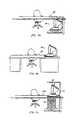
- FIG. 1shows a perspective view of a teleconferencing robot 100 placed on a rolling stand 10.
- the teleconferencing robot 100has a swivel base 20 having a lower stage 22 secured to the stand and rotating upper stage 24 rotatable about a vertical axis with respect to lower stage 22.
- the rotating upper stage 24has a defined forward direction. In the preferred embodiment of the invention, the top-front portion of rotating upper stage 24 is rounded and forwardly sloped to prevent loose items from being placed there.
- a video monitor 40is placed on or fastened to the top-rear portion of the rotating upper stage 24.
- a supporting arm 12extends from the lower stage 22 and supports a platform 16 positioned just above the video monitor 40. The platform 16 supports a speaker location system 60.
- the speaker location systemincludes a video camera 50 with a pan/tilt video camera base 52.
- Microphones 62a, 62b and 62cpick up the sound coming from the person speaking and generate an appropriate control signal to control the pan/tilt video camera base 52 and the zoom on the video camera 50 so that the video camera 50 is directed at the person speaking.
- FIGS. 2a-2cthe swiveling feature of the teleconferencing robot 100 is shown in a series of three perspective views.
- the teleconferencing robot 100is shown in a default starting position with video monitor 40, video camera 50 and microphones 62a, 62b and 62c substantially directed in the same forward direction as that defined by the forward direction of rotating upper stage 24 of swivel base 20.
- FIG. 2bin response to a control signal, the rotating upper stage 24 of the swivel base 20, the video monitor 40 and the video camera 50 have turned partially towards the viewer/speaker (viewer/speaker not shown but assumed to be in the same viewing position for all of FIGS. 2a-2c).
- FIG. 2cthe rotating upper stage 24, video monitor 40, and video camera 50 have turned fully towards the viewer/speaker. During this turning operation, the rotating upper stage 24, video monitor 40, and video camera 50 are substantially synchronized to each other.
- the rolling stand 10, the supporting arm 12, the lower stage 22 of the swivel base 20, platform 16 and microphones 62a, 62b and 62cremain fixed in position during the swiveling operation illustrated in FIGS. 2a-2c.
- FIG. 3shows a side view of the teleconferencing robot 100 with a simplified cut-out view of swivel base 20.
- the rotating upper stage 24 and lower stage 22are connected by a swiveling mechanism 25.
- Alternative coupling arrangements between the rotating upper stage 24 and lower stage 22are possible.
- a swivel point 21is formed.
- the rotating upper stage 24rotates about a vertical axis passing through the swivel point 21.
- the rotating upper stage 24is engaged to a rotating upper stage drive unit 30, such as a servo-motor, which can swivel the rotating upper stage 24 about the vertical axis passing through the swivel point 21.
- a micro-controller 28controls the rotating upper stage drive unit 30. A detailed description of this function is provided later with reference to FIGS. 9-11.
- the screen of video monitor 40is placed at or near the vertical axis passing through the swivel point 21 so that the screen of video monitor 40 may be viewed from a wider angle. If the screen of video monitor 40 is positioned too far forward, then the viewing angle will be significantly reduced for those conferees who are sitting to either side and close to the video monitor 40.
- the placement of the screen of video monitor 40is such that two straight lines lying in a horizontal plane and crossing at the vertical axis passing through the swivel point 21, and touching the left and right edges of the screen of video monitor 40, respectively, form an angle of 160° to 200°.
- FIGS. 4a-4cshow some desk storage arrangements for the teleconferencing robot 100 with a desk shown at 170.
- FIG. 4ashows one possible storage arrangement for the teleconferencing robot 100 where the teleconferencing robot is positioned under the desk 170. The desk is then provided with a removable panel to enable the robot 100 to be raised, in a manner described below, to a position flush with the top of the desk 170.
- FIG. 4bshows the teleconferencing robot 100 mounted in an operating position, on the desktop.
- FIG. 4cshows an alternative storage arrangement where the supporting arm 12 supports a removable desktop panel 18.
- a vertical lifting and lowering mechanism 70raises the teleconferencing robot 100 raises into an operating position, level with the desktop, and simultaneously displaces the panel 18 vertically upwards.
- FIG. 5shows a simplified side cross-sectional view of a further embodiment of the teleconferencing robot 100 provided with the vertical lifting and lowering mechanism 70 and a mobile ground unit 80.
- the vertical lifting and lowering mechanism 70comprises piston assemblies 71a, 71b and 71c which may be extended and retracted in concert to raise and lower the teleconferencing robot 100.
- the piston assemblies 71a, 71care parallel and spaced apart, so that the three piston assemblies provide three point support.
- Piston assembly drive units 74a, 74b and 74care operationally engaged to piston assemblies 71a, 71b and 71c, respectively.
- Vertical lifting and lowering control unit 73controls the piston drive units 74a, 74b and 74c.
- the piston assemblies 71a, 71b and 71care protected and hidden by a flexible accordion sleeve 72. A more detailed description of the operation of the vertical lifting and lowering mechanism is provided later, with particular reference to FIG. 12.
- the mobile ground unit 80houses a power source 87, drive motors 81a and 81b engaged to drive wheels 82 and 83, respectively, and a mobile ground unit control 88 to control the direction and speed of drive motors 81a and 81b.
- the mobile ground unit 80is remotely controllable by using a remote control unit 89.
- instructions transmitted by a radio signal from the remote control unit 89are received by an antenna 86 and relayed down to the mobile ground control unit 88.
- many other communication meansare possible. A more detailed description of the operation of the mobile ground unit 80 is provided later with particular reference to FIG. 13.
- FIGS. 6a-6cshow the teleconferencing robot 100 and mobile ground unit 80 in operation.
- FIG. 6ashows the teleconferencing robot 100 and the mobile ground unit 80 in a default starting position, with rotating upper stage 24, lower stage 22, video monitor 40 and dynamic speaker locating system 60 all oriented in a defined forward direction.
- the forward path of mobile ground unit 80i.e. the direction of travel if both drive wheels 82 and 83 are engaged in the same direction at the same speed
- FIG. 6bshows the teleconferencing robot with the rotating upper stage 24. video monitor 40 and video camera 50 all rotated to face the viewer.
- the mobile ground unit 80turns toward the viewer while the rotating upper stage 24, video monitor 40 and video camera 50 simultaneously turn in the opposite direction at the same rate of rotation, i.e. so as to appear to remain stationary.
- the resulting positionis shown in FIG. 6C. Consequently, the remote conferee can maintain "eye contact" with the viewer when turning the mobile ground unit 80 to approach the viewer. The details of this operation will be further described below with reference to FIGS. 9-13.
- FIGS. 7a-7cthe vertical lifting and lowering mechanism 70 is shown in operation.
- FIG. 7ashows the vertical lifting and lowering mechanism 70 fully retracted.
- FIG. 7bshows the vertical lifting and lowering mechanism 70 in a partially raised position.
- FIG. 7cshows the vertical lifting and lowering mechanism 70 in a fully extended position.
- the height of the teleconferencing robot 100 when the vertical lifting and lowering mechanism 70 is fully extendedrepresents approximately the height of a standing person.
- the vertical lifting and lowering mechanism 70is adjustable to any height between the fully extended and fully retracted positions, shown in FIG. 7c and FIG. 7a respectively, so that an appropriate height can be established for a given situation.
- the heightmight be appropriately adjusted to represent a sitting position.
- the vertical lifting and lowering mechanism 70may be extended to reflect the remote conferee's height.
- the remote confereemay want to match the height of the person to whom the remote conferee is speaking.
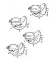
- FIGS. 8a-8dthe operation of the attention- getting mechanism 90 is shown.
- FIG. 8ashows a representation of a hand and arm 90 in a standby position, laying against the side of video monitor 40.
- FIG. 8bshows the movement of the hand and arm 90 by rotation outwardly from the shoulder coupling point 91 so that it is then at an angle from the side of video monitor 40.
- FIG. 8cshows a further action of hand and arm 90 where it is rotated through a 90° angle about an axis along the arm thereof such that the hand appears to be in a "palm-open" position in relation to the viewer.
- FIG. 8ashows a representation of a hand and arm 90 in a standby position, laying against the side of video monitor 40.
- FIG. 8bshows the movement of the hand and arm 90 by rotation outwardly from the shoulder coupling point 91 so that it is then at an angle from the side of video monitor 40.
- FIG. 8cshows a further action of hand and arm 90 where it is rotate
- FIG. 8dshows the representation of a hand and arm 90 in the palm-open position being rotated alternately outwardly and inwardly to mimic a waving motion.
- a motionmay be easily achieved, for example, by using motors and mechanisms similar to that used for automobile windshield wipers.
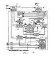
- FIG. 9is a simplified block diagram showing the interconnection between the remote teleconferencing unit 120, located at the remote conferee's site, and the teleconferencing robot 100, located at the local group meeting site.
- Audio/video/data communications controllers 128 and 129receive and transmit a plurality of audio-, video-and data-signals between the remote teleconferencing unit 120 and the teleconferencing robot 100 via a transmission system 130, which can be any suitable transmission system, including known telephone lines, wireless transmission, etc.
- the plurality of signals shown in FIG. 9are explained in greater detail below.
- the teleconferencing robot 100includes the micro-controller 28 which controls the attention getting mechanism 90 as well as various other teleconferencing robot components represented by block 99.
- the micro-controller 28also controls the vertical lifting and lowering mechanism 70 and mobile ground unit 80 when provided, both of these units being optional.
- Remote teleconferencing unit 120includes a microphone 121 to pick up the voice of the remote conferee and send a RTU outgoing audio signal (“RTUOAS”) to audio/video/data communications controller 128 (“AVDCC 128").
- RTU 120includes a microphone 121 to pick up the voice of the remote conferee and send a RTU outgoing audio signal (“RTUOAS”) to audio/video/data communications controller 128 (“AVDCC 128").
- the AVDCC 128controls the transmission and reception of all of the various RTU signals to and from an equivalent communications controller, AVDCC 129 (shown in FIG. 9), located at the local group meeting site.
- RTU 120further includes a video camera 122 to capture an image of the remote conferee.
- the video camera 122sends an RTU outgoing video signal ("RTUOVS") to AVDCC 128.
- Amplified speaker 123receives an RTU incoming audio signal (“RTUIAS”) from AVDCC 128.
- the RTUIASoriginates from the teleconferencing robot 100 (shown in FIG. 9) and typically consists of the voices of the local conferees at the group meeting site.
- RTU 120further includes a teleconferencing robot remote control system 119 which remotely controls the operation of the teleconferencing robot 100 of FIG. 9.
- the teleconferencing robot remote control system 119comprises a video monitor 124, an operations panel 125, a graphics overlay unit 126 and a main control unit 127.
- the remote confereecontrols the teleconferencing robot 100 of FIG. 9 by means of input at the operations panel 125.
- Operations panel 125may be a keyboard, joystick, mouse or any other input device or a combination thereof.
- the main control unit 127receives the input from operations panel 127 and sends out an RTU outgoing data signal ("RTUODS”) to AVDCC 128 and eventually to micro-controller 28 of FIG. 9.
- RTUODSRTU outgoing data signal
- the RTUODScontains instructions and control signals to control the various functions of the teleconferencing robot 100 of FIG. 9.
- the main control unit 127also provides feedback to the remote conferee by means of graphics overlay unit 126 which may display various characters, symbols and icons on video monitor 124.
- graphics overlay unit 126may display various characters, symbols and icons on video monitor 124.
- An RTU incoming video signal (“RTUTVS") originating from the teleconferencing robot 100 of FIG. 9is received by the graphics overlay unit 126 and is passed through to video monitor 124, either with or without any characters, symbols and icons superimposed on the video image created by the RTUIVS on video monitor 124.
- the main control unit 127further receives an RTU incoming data signal ("RTUIDS") which contains a plurality of feedback signals from the teleconferencing robot 100, the vertical lifting and lowering mechanism 70 and the mobile ground unit 80, all shown in FIG. 9.
- RTUIDSRTU incoming data signal
- Some of the feedback contained in the RTUIDSmay be represented graphically to the remote conferee via the graphics overlay unit 126 and video monitor 124.
- a graphicmay show the current rotational position of the rotating upper stage 24 of FIGS. 2a-2c so that the remote conferee is aware of any limitations of turning further left or further right.
- the micro-controller 28controls the operation of various components based on control instructions received from the main control unit 127 shown in FIG. 9. These control instructions contained in the RTUODS are transmitted by the AVDCC 128 through the transmission system 130 and to the AVDCC 129, all shown on FIG. 9.
- the AVDCC 129 of FIG. 9transmits the same control instructions to the micro-controller 28 as the teleconferencing robot incoming data signal ("TRIDS") as shown on FIG. 11.
- the micro-controller 28also provides feedback to the main control unit 127 of FIG. 10 by means of the teleconferencing robot outgoing data signal ("TRODS") which is transmitted to the AVDCC 129 of FIG. 10.
- the micro-controller 28activates the attention-getting mechanism 90 upon receiving an instruction from the remote conferee via the operations panel 125 shown in FIG. 10. Activation causes the attention-getting mechanism to rotate the representation of the hand and arm outwards, twist the hand 90° into a "palm-open” position, then start a waving motion back and forth, as illustrated in FIGS. 8a-8d, above.
- the required motionmay be obtained quite easily, for example, by using mechanisms and motors similar to that used for automobile windshield wipers.
- the swiveling feature of the teleconferencing robot 100can be either automatic or manually controlled by the remote conferee.
- a switch unit 63receives a speaker location control signal ("SLCS") to control the zoom function of video camera 50 and control the pan/tilt video camera base 52.
- the switch unit 63also receives a teleconferencing robot control signal (“TRCS") from the micro-controller 28.
- the remote confereecan cause the switch unit 63 to switch between automatic mode, where the SLCS is used, and manual mode, where the remote conferee provides the pan, tilt and zoom signals.
- the speaker location control unit 61receives input signals from a microphone array 62 comprising three microphones 62a, 62b and 62c, as shown in FIG. 1. Using the signals from the microphone array 62, the speaker location control unit 61 determines from which direction the sound is coming from. The speaker location control unit 61 then produces the SLCS to control the zoom function of video camera 50 and control the pan/tilt video camera base 52.
- the remote confereeFor manual mode, the remote conferee first sends a switch signal to switch unit 63 to enter the manual mode. Then, the remote conferee provides pan, tilt and zoom control signals via the operations panel 125, shown in FIG. 10. The remote conferee can switch back to automatic mode by sending another switch signal to switch unit 63.
- the switch unit 63sends on a pan/tilt/zoom control signal ("PTZCS") to the camera pan/tilt/zoom control unit 64.
- the camera pan/tilt/zoom control unit 64controls pan drive unit 53, tilt drive unit 54 and zoom drive unit 55 to drive the pan/tilt video camera base 52 and the zoom on video camera 50.
- the camera pan/tilt/zoom control unit 64also provides a teleconferencing robot feedback signal 1 ("TRFS1") to the micro-controller 28 to communicate to the main control unit 127 of FIG. 10 the camera pan/tilt/zoom control information.
- TRFS1teleconferencing robot feedback signal 1
- the pan control signal (“PCS”) from the camera pan/tilt/zoom control unit 64 to the pan drive unit 53is split and is also provided as an input to switch unit 57.
- An optional position sensor 56is positioned to read the position and rotation of the pan base of pan/tilt video camera base 52.
- the position sensor 56provides a position sensor feedback signal ("PSFS") which is compatible with the PCS signal and which provides essentially the same pan position and rotation information.
- PSFSposition sensor feedback signal
- the position sensor 56may be any number of devices which senses the panning movement of the pan/tilt video camera base 52. Two such devices are shown in FIGS. 11a and 11b, operationally coupled to the pan/tilt video camera bases 52a and 52b, respectively.
- FIG. 11ashows a perspective view of one embodiment of a position sensor 56a with a shaft head 150 mechanically engaged to the pan/tilt video camera base 52a by a wire 151 set at an appropriate tension to cause the shaft head 150 to rotate as the pan/tilt video camera base 52a pans left and right.
- a base 152 of the position sensor 56agenerates a signal corresponding to the rotation of the shaft head 150 and the signal is transmitted via a communication link 153 to the switch unit 57 of FIG. 10.
- FIG. 11bshows a side view of another embodiment of a position sensor 56b with a shaft head 160 frictionally engaged to a spherical, dome shaped top of a pan/tilt video camera base 52b.
- the rotation of the pan/tilt video camera base 52bcauses the shaft head 160 to rotate.
- a base 162 of the position sensor 56bgenerates a signal corresponding to the rotation of the shaft head 160 and the signal is transmitted via a communication link 163 to switch unit 57 of FIG. 11.
- the switch unit 57can be manually set to pass on either the PCS signal or the PSFS signal from the optical position sensor 56.
- the switch unit 57passes on the selected signal as a rotating upper stage control signal ("RUSCS") to the rotating upper stage drive unit 23.
- the rotating upper stage drive unitreceives the RUSCS and drives the rotating upper stage 24 left or right. Since the RUSCS is either the PCS or the PSFS, both of which provide information on the video camera 50 pan position, the rotating upper stage 24 is essentially driven to the same pan position as the video camera 50.
- the rotating upper stage drive unit 23provides a teleconferencing robot feedback signal 2 ("TRFS2") to the micro-controller 28 so that the remote conferee is aware of the position of the rotating upper stage 24.
- TRFS2teleconferencing robot feedback signal 2
- the video monitor 40displays a substantially life-sized image of the remote conferee's face on the screen. This image is received as the teleconferencing robot incoming video signal ("TRIVS") from the AVDCC 129, shown in FIG. 9.
- the TRIVScorresponds to the RTUOVS shown in FIG. 10.
- Video monitor 40is placed on or fastened to the rotating upper stage 24, as shown in FIG. 1. Thus, the video monitor 40 is rotating with the rotating upper stage 24 and is essentially synchronized to the pan position and rotation of the video camera 50.
- the video camera 50provides and image of the local conferee, typically the local conferee that is speaking, and sends a teleconferencing robot outgoing video signal ("TROVS") to the AVDCC 129 of FIG. 9.
- TROVScorresponds to the RTUFVS of FIG. 10.
- Microphone 42picks up the sound from the local conferees and sends a teleconferencing robot outgoing audio signal ("TROAS") to the AVDCC 129.
- TROASteleconferencing robot outgoing audio signal
- the sound picked up by the microphone array 62may be supplied as the TROAS (this optional configuration is not shown in FIG. 11).
- the TROAScorresponds to the RTUIAS of FIG. 10.
- the amplified speaker 26receives a teleconferencing robot incoming video signal ("TRIAS") from the AVDCC 129, shown in FIG. 9.
- TRIASteleconferencing robot incoming video signal
- the TRIAScorresponds to the RTUOAS of FIG. 10 and provides the local conferees with sound from the remote conferee.
- VLLM 70a schematic of the vertical lifting and lowering mechanism 70
- the VLLM 70comprises piston assemblies 71a, 71b and 71c which are positioned in an arrangement as shown in FIG. 5.
- Piston assembly drive units 74a, 74b and 74cdrive the piston assemblies 71a, 71b and 71c respectively.
- the piston assembly drive units 74a, 74b and 74care controlled by the vertical lifting and lowering control unit 73 ("VLLCU 73").
- the VLLCU 73receives a vertical lifting and lowering control signal (“VLLCS”) from the micro-controller 28 of FIG. 9.
- VLLCU 73also provides a vertical lifting and lowering feedback signal (“VLLFS”) to the micro-controller 28 of FIG. 9 so that the remote conferee receives feedback as to the state of the VLLM 70.
- VLLCSvertical lifting and lowering control signal
- the piston assemblies 71a, 71b and 71care extended in concert at the same rate, starting from a fully retracted position as shown in FIG. 7a.
- the piston assembles 71a, 71b and 71chidden inside the flexible accordion sleeve 72
- the piston assemblies 71a, 71b and 71care retracted at the same rate.
- the teleconferencing robot 100can be set at a height anywhere between a fully retracted and fully extended position.
- the center piston assembly 71bcan be extended less than the outer piston assembles 71a and 71c. This will cause the teleconferencing robot 100 to tilt forward and assume a bowing position. Extension of the center piston assembly 71c back to the same extension of the outer piston assemblies 71a and 71c will cause the teleconferencing robot to return to an up-right position.
- FIG. 13a schematic diagram of the mobile ground unit 80 (“MGU 80") is shown.
- a power source 87provides power to MGU control 88 and the wheel drive motors 81a and 81b.
- the MGU control 88receives an MGU control signal (“MGUCS”) from the micro-controller 28, as shown in FIG. 9.
- the MGU control 88provides a MGU feedback signal (“MGUFS”) back to the micro-controller 28 to provide feedback about the MGU to the remote conferee.
- the MGUCScontains control information to operate the rotation speed and direction of rotation of the drive wheels 82 and 83.
- the left wheel drive motor 81a and the right wheel drive motor 81bturn the drive wheels 82 and 83 in a forward direction at the same rate. Reversing the direction causes the MGU 80 to move backwards, but this will typically not be used since the remote conferee requires visual feedback from the video camera 50, as shown in FIGS. 6a-6c, in order to operate the MGU 80.
- the right wheel drive motor 81bwill hold the right drive wheel 83 stationary while the left wheel drive motor 81a drives the left drive wheel in a forward direction.
- the right wheel drive motor 81bcan drive the right drive wheel 83 at a slower rate than the left wheel drive motor 81a is driving the left drive wheel 82.
- the right wheel drive motor 81bcan drive the right drive wheel 83 in a reverse direction at the same rate as the left wheel drive motor 81a drives the left drive wheel 82 in a forward direction. Left turns can be made in an analogous fashion with the wheels and directions reversed.
- the teleconferencing robot 100is operated as described above so that the video monitor 40 is directed towards the viewer.
- the MGU 80is operated to turn left while staying in position.
- the rotating upper stage drive unit 23provides a feedback signal, TRFS2, to the micro-controller 28.
- TRFS2the micro-controller 28 then calculates the amount of rotation required by the MGU 80 to rotate into position.
- the micro-controller 28then sends appropriate control signals TRCS and MGUCS (shown in FIG. 9) so that the MGU 80 is rotating in position towards the viewer and the rotating upper stage 24 and the video camera 50 are rotating at the same rate of rotation but in the opposite direction.
- a ceiling mounted swivel mechanismmay be used to support a hanging video monitor.
- the video camera and speaker location unitmay be fastened to a platform hanging beneath the video monitor.
- a vertical lifting and lowering mechanismmay be mounted from the ceiling to raise and lower a video monitor from the ceiling.
- FIGS. 14a-14cthe rotating upper stage 24 and lower stage 22 of FIG. 1 are replaced by rotating upper stage 24a and lower stage 22a.
Landscapes
- Engineering & Computer Science (AREA)
- Multimedia (AREA)
- Signal Processing (AREA)
- Two-Way Televisions, Distribution Of Moving Picture Or The Like (AREA)
- Telephonic Communication Services (AREA)
Description
Claims (20)
- A teleconferencing robot, for enabling a remote conferee to projecta sense of presence into a group meeting, the teleconferencing robot comprising:wherein said video monitor and video camera move in response tosaid input control signal to enable a remote conferee to project a sense of presenceinto the group meeting.a base;a video monitor movably mounted to the base for receiving anddisplaying an image of the remote conferee;a video camera movably mounted on the base;control means mounted on the base for moving the video monitor andvideo camera in response to an input control signal; and
- A teleconferencing robot as claimed in claim 1, wherein the videomonitor is rotatably mounted to the base unit, for rotation about a substantiallyvertical axis; and
wherein the control means includes a rotating drive unit for rotationof the video monitor. - A teleconferencing robot as claimed in claim 2, wherein thevideo camera is rotatably mounted with the video monitor to the base unit;and
wherein the rotating drive unit rotates the video monitor and video camera. - A teleconferencing robot as claimed in claim 2, wherein the videocamera is rotatably mounted to the base, for rotation about a substantially verticalaxis; and
wherein the control means includes a pan drive unit for rotation of thevideo camera. - A teleconferencing robot as claimed in claim 3 or 4, wherein thevideo camera is additionally mounted so as to be tiltable upwards and downwards;and
wherein the control means includes a tilt drive unit for tilting thevideo camera upwards and downwards. - A teleconferencing robot as claimed in any preceding claim, whereinsaid input control signal is derived from sound source detection means such that saidcontrol signal represents the direction of said sound source with respect to saidmonitor and said control means being adapted to drive said video monitor, inresponse to said control signal, to a position substantially facing said detecteddirection.
- A teleconferencing robot as claimed in any preceding claim, whereinthe base comprises upper and lower stages, wherein the video monitor is secured tothe upper stage, and the lower and upper stages are rotatable relative to one another about a substantially vertical axis; and
wherein the upper stage has a defined forward direction with thevideo monitor normally being directed in said defined forward direction. - A teleconferencing robot as claimed in any preceding claim, whereinthe base comprises an upper part on which the video monitor is mounted and alower part, and means for vertically displacing the upper and lower parts relativeto one another.
- A teleconferencing robot as claimed in any preceding claim, whereinthe base comprises an upper part on which the video monitor is mounted and alower part; and
wherein the lower part of the base comprises a mobile ground unitincluding wheels and drive motors for rotating the wheels, to drive theteleconferencing robot across the ground. - A teleconferencing robot as claimed in any of claims 2 to 5, whereinthe screen of the video monitor is positioned at or near the vertical axis about whichthe video monitor rotates such that the angle formed by two straight lines lying ina horizontal plane crossing at the vertical axis and further extending through left andright hand edges of the screen of the video monitor is substantially 160°-200°.
- A teleconferencing robot as claimed in any preceding claim, furthercomprising an attention getting means for getting the attention of other conferees; and
wherein the control means includes means for actuating the attentiongetting means. - A teleconferencing robot as claimed in claim 11, wherein the attentiongetting means comprises a representation of a hand and arm; and
wherein a free end of the arm is mechanically coupled to the base,whereby said representation of a hand and arm may be rotated alternatively inwardlyand outwardly, to mimic a waving motion. - A teleconferencing robot as claimed in any preceding claim, incombination with a remote teleconferencing unit which comprises a secondmicrophone and a second video camera for obtaining an audio signal and an imagefrom the remote conferee for transmission to the video monitor of theteleconferencing robot, and a second video monitor and a second speaker forproviding an image and an audio signal received from the teleconferencing robot;
wherein the video monitor of the teleconferencing robot is providedwith a speaker for outputting an audio signal received from the microphone of theremote teleconferencing unit; and
wherein the input control signal is provided by the remoteteleconferencing unit. - A teleconferencing robot in combination with a remoteteleconferencing unit as claimed in claim 13, wherein the remote teleconferencing unit and the teleconferencing robot are each provided with a respectivecommunications controller for audio, video and data signals, for communicationtherebetween over a transmission system; and
wherein the communications controllers transmit audio and videosignals in both directions between the remote teleconferencing unit and theteleconferencing robot, and data signals to the teleconferencing robot, for controllingthe teleconferencing robot and data signals back to the remote teleconferencing unit,to provide information on movement of the teleconferencing robot. - A teleconferencing robot as claimed in any preceding claim, furthercomprising microphone array means for enabling a location of a speaker to bedetermined and generating a detection signal indicative of the location of the speaker
wherein the input control signal is derived from the detection signal and causes therotating drive unit to rotate the video monitor to a position substantially facing thelocation of the speaker. - A teleconferencing robot as claimed in claim 15, further comprisinga switch unit enabling the input control signal to be selectively derived from thedetection signal and a remote signal generated by the remote conferee.
- A teleconferencing robot as claimed in claim 15 or 16, wherein thebase comprises a supporting arm extending around and behind the video monitor andsupporting the video camera and the audio array means above the video monitor;and
wherein the microphone array means is fixed to the base such that the videocamera and the video monitor rotate independently of the microphone array means. - A teleconferencing robot as claimed in claim 17, wherein a screen ofthe video monitor is positioned near the vertical axis about which the video monitorrotates; and
wherein the video camera rotates substantially about the vertical axis. - A teleconferencing robot as claimed in any of claims 1 to 5, furthercomprising:
location determining means for enabling a location of a person to bedetermined and generating a detection signal indicative of the location of thespeaker;
wherein the location determining means is fixed to the base such thatthe video camera and the video monitor rotate independently of the locationdetermining means; and
wherein the input control signal is derived from the detection signaland causes the rotating drive unit and pan drive unit to rotate the video monitor andvideo camera, respectively, to a position substantially facing the location of thespeaker. - The teleconferencing robot as claimed in any preceding claim,
wherein the input control signal is derived from a remote signal generated by theremote conferee.
Applications Claiming Priority (3)
| Application Number | Priority Date | Filing Date | Title |
|---|---|---|---|
| US4579397P | 1997-05-07 | 1997-05-07 | |
| US45793P | 1997-05-07 | ||
| PCT/CA1998/000463WO1998051078A1 (en) | 1997-05-07 | 1998-05-06 | Teleconferencing robot with swiveling video monitor |
Publications (2)
| Publication Number | Publication Date |
|---|---|
| EP0981905A1 EP0981905A1 (en) | 2000-03-01 |
| EP0981905B1true EP0981905B1 (en) | 2002-01-09 |
Family
ID=21939919
Family Applications (1)
| Application Number | Title | Priority Date | Filing Date |
|---|---|---|---|
| EP98921290AExpired - LifetimeEP0981905B1 (en) | 1997-05-07 | 1998-05-06 | Teleconferencing robot with swiveling video monitor |
Country Status (6)
| Country | Link |
|---|---|
| EP (1) | EP0981905B1 (en) |
| JP (1) | JP2001524286A (en) |
| AU (1) | AU7420398A (en) |
| CA (1) | CA2289697C (en) |
| DE (1) | DE69803451T2 (en) |
| WO (1) | WO1998051078A1 (en) |
Cited By (50)
| Publication number | Priority date | Publication date | Assignee | Title |
|---|---|---|---|---|
| US6925357B2 (en) | 2002-07-25 | 2005-08-02 | Intouch Health, Inc. | Medical tele-robotic system |
| US7222000B2 (en) | 2005-01-18 | 2007-05-22 | Intouch Technologies, Inc. | Mobile videoconferencing platform with automatic shut-off features |
| US7262573B2 (en) | 2003-03-06 | 2007-08-28 | Intouch Technologies, Inc. | Medical tele-robotic system with a head worn device |
| US7593030B2 (en) | 2002-07-25 | 2009-09-22 | Intouch Technologies, Inc. | Tele-robotic videoconferencing in a corporate environment |
| US7761185B2 (en) | 2006-10-03 | 2010-07-20 | Intouch Technologies, Inc. | Remote presence display through remotely controlled robot |
| US7769492B2 (en) | 2006-02-22 | 2010-08-03 | Intouch Technologies, Inc. | Graphical interface for a remote presence system |
| US7813836B2 (en) | 2003-12-09 | 2010-10-12 | Intouch Technologies, Inc. | Protocol for a remotely controlled videoconferencing robot |
| US8077963B2 (en) | 2004-07-13 | 2011-12-13 | Yulun Wang | Mobile robot with a head-based movement mapping scheme |
| US8116910B2 (en) | 2007-08-23 | 2012-02-14 | Intouch Technologies, Inc. | Telepresence robot with a printer |
| US8170241B2 (en) | 2008-04-17 | 2012-05-01 | Intouch Technologies, Inc. | Mobile tele-presence system with a microphone system |
| US8179418B2 (en) | 2008-04-14 | 2012-05-15 | Intouch Technologies, Inc. | Robotic based health care system |
| US8340819B2 (en) | 2008-09-18 | 2012-12-25 | Intouch Technologies, Inc. | Mobile videoconferencing robot system with network adaptive driving |
| US8384755B2 (en) | 2009-08-26 | 2013-02-26 | Intouch Technologies, Inc. | Portable remote presence robot |
| US8463435B2 (en) | 2008-11-25 | 2013-06-11 | Intouch Technologies, Inc. | Server connectivity control for tele-presence robot |
| US8515577B2 (en) | 2002-07-25 | 2013-08-20 | Yulun Wang | Medical tele-robotic system with a master remote station with an arbitrator |
| US8670017B2 (en) | 2010-03-04 | 2014-03-11 | Intouch Technologies, Inc. | Remote presence system including a cart that supports a robot face and an overhead camera |
| US8718837B2 (en) | 2011-01-28 | 2014-05-06 | Intouch Technologies | Interfacing with a mobile telepresence robot |
| US8836751B2 (en) | 2011-11-08 | 2014-09-16 | Intouch Technologies, Inc. | Tele-presence system with a user interface that displays different communication links |
| US8849680B2 (en) | 2009-01-29 | 2014-09-30 | Intouch Technologies, Inc. | Documentation through a remote presence robot |
| US8849679B2 (en) | 2006-06-15 | 2014-09-30 | Intouch Technologies, Inc. | Remote controlled robot system that provides medical images |
| US8892260B2 (en) | 2007-03-20 | 2014-11-18 | Irobot Corporation | Mobile robot for telecommunication |
| US8930019B2 (en) | 2010-12-30 | 2015-01-06 | Irobot Corporation | Mobile human interface robot |
| US8935005B2 (en) | 2010-05-20 | 2015-01-13 | Irobot Corporation | Operating a mobile robot |
| US8996165B2 (en) | 2008-10-21 | 2015-03-31 | Intouch Technologies, Inc. | Telepresence robot with a camera boom |
| US9014848B2 (en) | 2010-05-20 | 2015-04-21 | Irobot Corporation | Mobile robot system |
| US9138891B2 (en) | 2008-11-25 | 2015-09-22 | Intouch Technologies, Inc. | Server connectivity control for tele-presence robot |
| US9160783B2 (en) | 2007-05-09 | 2015-10-13 | Intouch Technologies, Inc. | Robot system that operates through a network firewall |
| US9174342B2 (en) | 2012-05-22 | 2015-11-03 | Intouch Technologies, Inc. | Social behavior rules for a medical telepresence robot |
| US9193065B2 (en) | 2008-07-10 | 2015-11-24 | Intouch Technologies, Inc. | Docking system for a tele-presence robot |
| US9198728B2 (en) | 2005-09-30 | 2015-12-01 | Intouch Technologies, Inc. | Multi-camera mobile teleconferencing platform |
| US9251313B2 (en) | 2012-04-11 | 2016-02-02 | Intouch Technologies, Inc. | Systems and methods for visualizing and managing telepresence devices in healthcare networks |
| US9264664B2 (en) | 2010-12-03 | 2016-02-16 | Intouch Technologies, Inc. | Systems and methods for dynamic bandwidth allocation |
| US9323250B2 (en) | 2011-01-28 | 2016-04-26 | Intouch Technologies, Inc. | Time-dependent navigation of telepresence robots |
| US9361021B2 (en) | 2012-05-22 | 2016-06-07 | Irobot Corporation | Graphical user interfaces including touchpad driving interfaces for telemedicine devices |
| US9498886B2 (en) | 2010-05-20 | 2016-11-22 | Irobot Corporation | Mobile human interface robot |
| US9610685B2 (en) | 2004-02-26 | 2017-04-04 | Intouch Technologies, Inc. | Graphical interface for a remote presence system |
| US9842192B2 (en) | 2008-07-11 | 2017-12-12 | Intouch Technologies, Inc. | Tele-presence robot system with multi-cast features |
| US9974612B2 (en) | 2011-05-19 | 2018-05-22 | Intouch Technologies, Inc. | Enhanced diagnostics for a telepresence robot |
| US10334205B2 (en) | 2012-11-26 | 2019-06-25 | Intouch Technologies, Inc. | Enhanced video interaction for a user interface of a telepresence network |
| US10343283B2 (en) | 2010-05-24 | 2019-07-09 | Intouch Technologies, Inc. | Telepresence robot system that can be accessed by a cellular phone |
| US10762170B2 (en) | 2012-04-11 | 2020-09-01 | Intouch Technologies, Inc. | Systems and methods for visualizing patient and telepresence device statistics in a healthcare network |
| US10769739B2 (en) | 2011-04-25 | 2020-09-08 | Intouch Technologies, Inc. | Systems and methods for management of information among medical providers and facilities |
| US10808882B2 (en) | 2010-05-26 | 2020-10-20 | Intouch Technologies, Inc. | Tele-robotic system with a robot face placed on a chair |
| US10875182B2 (en) | 2008-03-20 | 2020-12-29 | Teladoc Health, Inc. | Remote presence system mounted to operating room hardware |
| US10969766B2 (en) | 2009-04-17 | 2021-04-06 | Teladoc Health, Inc. | Tele-presence robot system with software modularity, projector and laser pointer |
| US11636944B2 (en) | 2017-08-25 | 2023-04-25 | Teladoc Health, Inc. | Connectivity infrastructure for a telehealth platform |
| US11742094B2 (en) | 2017-07-25 | 2023-08-29 | Teladoc Health, Inc. | Modular telehealth cart with thermal imaging and touch screen user interface |
| US11862302B2 (en) | 2017-04-24 | 2024-01-02 | Teladoc Health, Inc. | Automated transcription and documentation of tele-health encounters |
| US12093036B2 (en) | 2011-01-21 | 2024-09-17 | Teladoc Health, Inc. | Telerobotic system with a dual application screen presentation |
| US12224059B2 (en) | 2011-02-16 | 2025-02-11 | Teladoc Health, Inc. | Systems and methods for network-based counseling |
Families Citing this family (22)
| Publication number | Priority date | Publication date | Assignee | Title |
|---|---|---|---|---|
| TW519826B (en)* | 1999-11-29 | 2003-02-01 | Koninkl Philips Electronics Nv | Personality-based intelligent camera system |
| US20120072024A1 (en)* | 2002-07-25 | 2012-03-22 | Yulun Wang | Telerobotic system with dual application screen presentation |
| US7158859B2 (en)* | 2003-01-15 | 2007-01-02 | Intouch Technologies, Inc. | 5 degrees of freedom mobile robot |
| US7158860B2 (en) | 2003-02-24 | 2007-01-02 | Intouch Technologies, Inc. | Healthcare tele-robotic system which allows parallel remote station observation |
| US7171286B2 (en) | 2003-02-24 | 2007-01-30 | Intouch Technologies, Inc. | Healthcare tele-robotic system with a robot that also functions as a remote station |
| US6888333B2 (en) | 2003-07-02 | 2005-05-03 | Intouch Health, Inc. | Holonomic platform for a robot |
| US7154526B2 (en)* | 2003-07-11 | 2006-12-26 | Fuji Xerox Co., Ltd. | Telepresence system and method for video teleconferencing |
| US7161322B2 (en) | 2003-11-18 | 2007-01-09 | Intouch Technologies, Inc. | Robot with a manipulator arm |
| US7092001B2 (en)* | 2003-11-26 | 2006-08-15 | Sap Aktiengesellschaft | Video conferencing system with physical cues |
| US7292912B2 (en) | 2003-12-05 | 2007-11-06 | Lntouch Technologies, Inc. | Door knocker control system for a remote controlled teleconferencing robot |
| US7756614B2 (en)* | 2004-02-27 | 2010-07-13 | Hewlett-Packard Development Company, L.P. | Mobile device control system |
| JP2005278147A (en)* | 2004-02-27 | 2005-10-06 | Sanin Denko Kk | Image communication system |
| US7643051B2 (en) | 2005-09-09 | 2010-01-05 | Roy Benjamin Sandberg | Mobile video teleconferencing system and control method |
| JP5233768B2 (en)* | 2009-03-18 | 2013-07-10 | 沖電気工業株式会社 | COMMUNICATION SUPPORT SYSTEM, DISPLAY CONTROL DEVICE, AND DISPLAY CONTROL METHOD |
| US11399153B2 (en) | 2009-08-26 | 2022-07-26 | Teladoc Health, Inc. | Portable telepresence apparatus |
| US11154981B2 (en) | 2010-02-04 | 2021-10-26 | Teladoc Health, Inc. | Robot user interface for telepresence robot system |
| JP5460793B2 (en)* | 2012-08-21 | 2014-04-02 | シャープ株式会社 | Display device, display method, television receiver, and display control device |
| KR20150070199A (en)* | 2012-10-01 | 2015-06-24 | 리볼브 로보틱스 인코포레이티드 | Robotic stand and systems and methods for controlling the stand during videoconference |
| JP2017208657A (en)* | 2016-05-17 | 2017-11-24 | 富士電機株式会社 | Observation apparatus and observation system |
| US20190033858A1 (en)* | 2017-07-28 | 2019-01-31 | Engineering Services Inc. | Telepresence robot |
| US10617299B2 (en) | 2018-04-27 | 2020-04-14 | Intouch Technologies, Inc. | Telehealth cart that supports a removable tablet with seamless audio/video switching |
| IT202100031355A1 (en)* | 2021-12-14 | 2023-06-14 | Renzo Braglia | INTERFACE DEVICE FOR TRADE EVENTS AND/OR VIRTUAL EXHIBITIONS |
Family Cites Families (2)
| Publication number | Priority date | Publication date | Assignee | Title |
|---|---|---|---|---|
| CH683659A5 (en)* | 1992-03-05 | 1994-04-15 | Schaerer Soehne Ag Usm U | Tele-video conference table for a video conference participant. |
| CA2148631C (en)* | 1994-06-20 | 2000-06-13 | John J. Hildin | Voice-following video system |
- 1998
- 1998-05-06JPJP54758498Apatent/JP2001524286A/enactivePending
- 1998-05-06WOPCT/CA1998/000463patent/WO1998051078A1/enactiveIP Right Grant
- 1998-05-06AUAU74203/98Apatent/AU7420398A/ennot_activeAbandoned
- 1998-05-06CACA002289697Apatent/CA2289697C/ennot_activeExpired - Fee Related
- 1998-05-06DEDE69803451Tpatent/DE69803451T2/ennot_activeExpired - Fee Related
- 1998-05-06EPEP98921290Apatent/EP0981905B1/ennot_activeExpired - Lifetime
Cited By (108)
| Publication number | Priority date | Publication date | Assignee | Title |
|---|---|---|---|---|
| US9849593B2 (en) | 2002-07-25 | 2017-12-26 | Intouch Technologies, Inc. | Medical tele-robotic system with a master remote station with an arbitrator |
| USRE45870E1 (en) | 2002-07-25 | 2016-01-26 | Intouch Technologies, Inc. | Apparatus and method for patient rounding with a remote controlled robot |
| US7142945B2 (en) | 2002-07-25 | 2006-11-28 | Intouch Technologies, Inc. | Medical tele-robotic system |
| US7158861B2 (en) | 2002-07-25 | 2007-01-02 | Intouch Technologies, Inc. | Tele-robotic system used to provide remote consultation services |
| US7164970B2 (en) | 2002-07-25 | 2007-01-16 | Intouch Technologies, Inc. | Medical tele-robotic system |
| US7164969B2 (en) | 2002-07-25 | 2007-01-16 | Intouch Technologies, Inc. | Apparatus and method for patient rounding with a remote controlled robot |
| US7218992B2 (en) | 2002-07-25 | 2007-05-15 | Intouch Technologies, Inc. | Medical tele-robotic system |
| US8209051B2 (en) | 2002-07-25 | 2012-06-26 | Intouch Technologies, Inc. | Medical tele-robotic system |
| US7142947B2 (en) | 2002-07-25 | 2006-11-28 | Intouch Technologies, Inc. | Medical tele-robotic method |
| US7289883B2 (en) | 2002-07-25 | 2007-10-30 | Intouch Technologies, Inc. | Apparatus and method for patient rounding with a remote controlled robot |
| US7310570B2 (en) | 2002-07-25 | 2007-12-18 | Yulun Wang | Medical tele-robotic system |
| US7593030B2 (en) | 2002-07-25 | 2009-09-22 | Intouch Technologies, Inc. | Tele-robotic videoconferencing in a corporate environment |
| US6925357B2 (en) | 2002-07-25 | 2005-08-02 | Intouch Health, Inc. | Medical tele-robotic system |
| US8515577B2 (en) | 2002-07-25 | 2013-08-20 | Yulun Wang | Medical tele-robotic system with a master remote station with an arbitrator |
| US10315312B2 (en) | 2002-07-25 | 2019-06-11 | Intouch Technologies, Inc. | Medical tele-robotic system with a master remote station with an arbitrator |
| US7262573B2 (en) | 2003-03-06 | 2007-08-28 | Intouch Technologies, Inc. | Medical tele-robotic system with a head worn device |
| US10882190B2 (en) | 2003-12-09 | 2021-01-05 | Teladoc Health, Inc. | Protocol for a remotely controlled videoconferencing robot |
| US7813836B2 (en) | 2003-12-09 | 2010-10-12 | Intouch Technologies, Inc. | Protocol for a remotely controlled videoconferencing robot |
| US9375843B2 (en) | 2003-12-09 | 2016-06-28 | Intouch Technologies, Inc. | Protocol for a remotely controlled videoconferencing robot |
| US9956690B2 (en) | 2003-12-09 | 2018-05-01 | Intouch Technologies, Inc. | Protocol for a remotely controlled videoconferencing robot |
| US9610685B2 (en) | 2004-02-26 | 2017-04-04 | Intouch Technologies, Inc. | Graphical interface for a remote presence system |
| US8401275B2 (en) | 2004-07-13 | 2013-03-19 | Intouch Technologies, Inc. | Mobile robot with a head-based movement mapping scheme |
| US9766624B2 (en) | 2004-07-13 | 2017-09-19 | Intouch Technologies, Inc. | Mobile robot with a head-based movement mapping scheme |
| US10241507B2 (en) | 2004-07-13 | 2019-03-26 | Intouch Technologies, Inc. | Mobile robot with a head-based movement mapping scheme |
| US8983174B2 (en) | 2004-07-13 | 2015-03-17 | Intouch Technologies, Inc. | Mobile robot with a head-based movement mapping scheme |
| US8077963B2 (en) | 2004-07-13 | 2011-12-13 | Yulun Wang | Mobile robot with a head-based movement mapping scheme |
| US7222000B2 (en) | 2005-01-18 | 2007-05-22 | Intouch Technologies, Inc. | Mobile videoconferencing platform with automatic shut-off features |
| US10259119B2 (en) | 2005-09-30 | 2019-04-16 | Intouch Technologies, Inc. | Multi-camera mobile teleconferencing platform |
| US9198728B2 (en) | 2005-09-30 | 2015-12-01 | Intouch Technologies, Inc. | Multi-camera mobile teleconferencing platform |
| US7769492B2 (en) | 2006-02-22 | 2010-08-03 | Intouch Technologies, Inc. | Graphical interface for a remote presence system |
| US8849679B2 (en) | 2006-06-15 | 2014-09-30 | Intouch Technologies, Inc. | Remote controlled robot system that provides medical images |
| US7761185B2 (en) | 2006-10-03 | 2010-07-20 | Intouch Technologies, Inc. | Remote presence display through remotely controlled robot |
| US8892260B2 (en) | 2007-03-20 | 2014-11-18 | Irobot Corporation | Mobile robot for telecommunication |
| US9296109B2 (en) | 2007-03-20 | 2016-03-29 | Irobot Corporation | Mobile robot for telecommunication |
| US9160783B2 (en) | 2007-05-09 | 2015-10-13 | Intouch Technologies, Inc. | Robot system that operates through a network firewall |
| US10682763B2 (en) | 2007-05-09 | 2020-06-16 | Intouch Technologies, Inc. | Robot system that operates through a network firewall |
| US8116910B2 (en) | 2007-08-23 | 2012-02-14 | Intouch Technologies, Inc. | Telepresence robot with a printer |
| US10875182B2 (en) | 2008-03-20 | 2020-12-29 | Teladoc Health, Inc. | Remote presence system mounted to operating room hardware |
| US11787060B2 (en) | 2008-03-20 | 2023-10-17 | Teladoc Health, Inc. | Remote presence system mounted to operating room hardware |
| US8179418B2 (en) | 2008-04-14 | 2012-05-15 | Intouch Technologies, Inc. | Robotic based health care system |
| US10471588B2 (en) | 2008-04-14 | 2019-11-12 | Intouch Technologies, Inc. | Robotic based health care system |
| US11472021B2 (en) | 2008-04-14 | 2022-10-18 | Teladoc Health, Inc. | Robotic based health care system |
| US8170241B2 (en) | 2008-04-17 | 2012-05-01 | Intouch Technologies, Inc. | Mobile tele-presence system with a microphone system |
| US10493631B2 (en) | 2008-07-10 | 2019-12-03 | Intouch Technologies, Inc. | Docking system for a tele-presence robot |
| US9193065B2 (en) | 2008-07-10 | 2015-11-24 | Intouch Technologies, Inc. | Docking system for a tele-presence robot |
| US10878960B2 (en) | 2008-07-11 | 2020-12-29 | Teladoc Health, Inc. | Tele-presence robot system with multi-cast features |
| US9842192B2 (en) | 2008-07-11 | 2017-12-12 | Intouch Technologies, Inc. | Tele-presence robot system with multi-cast features |
| US8340819B2 (en) | 2008-09-18 | 2012-12-25 | Intouch Technologies, Inc. | Mobile videoconferencing robot system with network adaptive driving |
| US9429934B2 (en) | 2008-09-18 | 2016-08-30 | Intouch Technologies, Inc. | Mobile videoconferencing robot system with network adaptive driving |
| US8996165B2 (en) | 2008-10-21 | 2015-03-31 | Intouch Technologies, Inc. | Telepresence robot with a camera boom |
| US10875183B2 (en) | 2008-11-25 | 2020-12-29 | Teladoc Health, Inc. | Server connectivity control for tele-presence robot |
| US8463435B2 (en) | 2008-11-25 | 2013-06-11 | Intouch Technologies, Inc. | Server connectivity control for tele-presence robot |
| US9138891B2 (en) | 2008-11-25 | 2015-09-22 | Intouch Technologies, Inc. | Server connectivity control for tele-presence robot |
| US10059000B2 (en) | 2008-11-25 | 2018-08-28 | Intouch Technologies, Inc. | Server connectivity control for a tele-presence robot |
| US12138808B2 (en) | 2008-11-25 | 2024-11-12 | Teladoc Health, Inc. | Server connectivity control for tele-presence robots |
| US8849680B2 (en) | 2009-01-29 | 2014-09-30 | Intouch Technologies, Inc. | Documentation through a remote presence robot |
| US10969766B2 (en) | 2009-04-17 | 2021-04-06 | Teladoc Health, Inc. | Tele-presence robot system with software modularity, projector and laser pointer |
| US8384755B2 (en) | 2009-08-26 | 2013-02-26 | Intouch Technologies, Inc. | Portable remote presence robot |
| US10911715B2 (en) | 2009-08-26 | 2021-02-02 | Teladoc Health, Inc. | Portable remote presence robot |
| US10404939B2 (en) | 2009-08-26 | 2019-09-03 | Intouch Technologies, Inc. | Portable remote presence robot |
| US9602765B2 (en) | 2009-08-26 | 2017-03-21 | Intouch Technologies, Inc. | Portable remote presence robot |
| US11798683B2 (en) | 2010-03-04 | 2023-10-24 | Teladoc Health, Inc. | Remote presence system including a cart that supports a robot face and an overhead camera |
| US9089972B2 (en) | 2010-03-04 | 2015-07-28 | Intouch Technologies, Inc. | Remote presence system including a cart that supports a robot face and an overhead camera |
| US8670017B2 (en) | 2010-03-04 | 2014-03-11 | Intouch Technologies, Inc. | Remote presence system including a cart that supports a robot face and an overhead camera |
| US10887545B2 (en) | 2010-03-04 | 2021-01-05 | Teladoc Health, Inc. | Remote presence system including a cart that supports a robot face and an overhead camera |
| US9498886B2 (en) | 2010-05-20 | 2016-11-22 | Irobot Corporation | Mobile human interface robot |
| US8935005B2 (en) | 2010-05-20 | 2015-01-13 | Irobot Corporation | Operating a mobile robot |
| US9014848B2 (en) | 2010-05-20 | 2015-04-21 | Irobot Corporation | Mobile robot system |
| US9902069B2 (en) | 2010-05-20 | 2018-02-27 | Irobot Corporation | Mobile robot system |
| US11389962B2 (en) | 2010-05-24 | 2022-07-19 | Teladoc Health, Inc. | Telepresence robot system that can be accessed by a cellular phone |
| US10343283B2 (en) | 2010-05-24 | 2019-07-09 | Intouch Technologies, Inc. | Telepresence robot system that can be accessed by a cellular phone |
| US10808882B2 (en) | 2010-05-26 | 2020-10-20 | Intouch Technologies, Inc. | Tele-robotic system with a robot face placed on a chair |
| US10218748B2 (en) | 2010-12-03 | 2019-02-26 | Intouch Technologies, Inc. | Systems and methods for dynamic bandwidth allocation |
| US9264664B2 (en) | 2010-12-03 | 2016-02-16 | Intouch Technologies, Inc. | Systems and methods for dynamic bandwidth allocation |
| US8930019B2 (en) | 2010-12-30 | 2015-01-06 | Irobot Corporation | Mobile human interface robot |
| US12093036B2 (en) | 2011-01-21 | 2024-09-17 | Teladoc Health, Inc. | Telerobotic system with a dual application screen presentation |
| US8718837B2 (en) | 2011-01-28 | 2014-05-06 | Intouch Technologies | Interfacing with a mobile telepresence robot |
| US9469030B2 (en) | 2011-01-28 | 2016-10-18 | Intouch Technologies | Interfacing with a mobile telepresence robot |
| US10399223B2 (en) | 2011-01-28 | 2019-09-03 | Intouch Technologies, Inc. | Interfacing with a mobile telepresence robot |
| US8965579B2 (en) | 2011-01-28 | 2015-02-24 | Intouch Technologies | Interfacing with a mobile telepresence robot |
| US9323250B2 (en) | 2011-01-28 | 2016-04-26 | Intouch Technologies, Inc. | Time-dependent navigation of telepresence robots |
| US11468983B2 (en) | 2011-01-28 | 2022-10-11 | Teladoc Health, Inc. | Time-dependent navigation of telepresence robots |
| US10591921B2 (en) | 2011-01-28 | 2020-03-17 | Intouch Technologies, Inc. | Time-dependent navigation of telepresence robots |
| US11289192B2 (en) | 2011-01-28 | 2022-03-29 | Intouch Technologies, Inc. | Interfacing with a mobile telepresence robot |
| US12224059B2 (en) | 2011-02-16 | 2025-02-11 | Teladoc Health, Inc. | Systems and methods for network-based counseling |
| US10769739B2 (en) | 2011-04-25 | 2020-09-08 | Intouch Technologies, Inc. | Systems and methods for management of information among medical providers and facilities |
| US9974612B2 (en) | 2011-05-19 | 2018-05-22 | Intouch Technologies, Inc. | Enhanced diagnostics for a telepresence robot |
| US10331323B2 (en) | 2011-11-08 | 2019-06-25 | Intouch Technologies, Inc. | Tele-presence system with a user interface that displays different communication links |
| US9715337B2 (en) | 2011-11-08 | 2017-07-25 | Intouch Technologies, Inc. | Tele-presence system with a user interface that displays different communication links |
| US8836751B2 (en) | 2011-11-08 | 2014-09-16 | Intouch Technologies, Inc. | Tele-presence system with a user interface that displays different communication links |
| US9251313B2 (en) | 2012-04-11 | 2016-02-02 | Intouch Technologies, Inc. | Systems and methods for visualizing and managing telepresence devices in healthcare networks |
| US10762170B2 (en) | 2012-04-11 | 2020-09-01 | Intouch Technologies, Inc. | Systems and methods for visualizing patient and telepresence device statistics in a healthcare network |
| US11205510B2 (en) | 2012-04-11 | 2021-12-21 | Teladoc Health, Inc. | Systems and methods for visualizing and managing telepresence devices in healthcare networks |
| US11515049B2 (en) | 2012-05-22 | 2022-11-29 | Teladoc Health, Inc. | Graphical user interfaces including touchpad driving interfaces for telemedicine devices |
| US9776327B2 (en) | 2012-05-22 | 2017-10-03 | Intouch Technologies, Inc. | Social behavior rules for a medical telepresence robot |
| US11453126B2 (en) | 2012-05-22 | 2022-09-27 | Teladoc Health, Inc. | Clinical workflows utilizing autonomous and semi-autonomous telemedicine devices |
| US10328576B2 (en) | 2012-05-22 | 2019-06-25 | Intouch Technologies, Inc. | Social behavior rules for a medical telepresence robot |
| US10892052B2 (en) | 2012-05-22 | 2021-01-12 | Intouch Technologies, Inc. | Graphical user interfaces including touchpad driving interfaces for telemedicine devices |
| US10603792B2 (en) | 2012-05-22 | 2020-03-31 | Intouch Technologies, Inc. | Clinical workflows utilizing autonomous and semiautonomous telemedicine devices |
| US10061896B2 (en) | 2012-05-22 | 2018-08-28 | Intouch Technologies, Inc. | Graphical user interfaces including touchpad driving interfaces for telemedicine devices |
| US9174342B2 (en) | 2012-05-22 | 2015-11-03 | Intouch Technologies, Inc. | Social behavior rules for a medical telepresence robot |
| US9361021B2 (en) | 2012-05-22 | 2016-06-07 | Irobot Corporation | Graphical user interfaces including touchpad driving interfaces for telemedicine devices |
| US10334205B2 (en) | 2012-11-26 | 2019-06-25 | Intouch Technologies, Inc. | Enhanced video interaction for a user interface of a telepresence network |
| US10924708B2 (en) | 2012-11-26 | 2021-02-16 | Teladoc Health, Inc. | Enhanced video interaction for a user interface of a telepresence network |
| US11910128B2 (en) | 2012-11-26 | 2024-02-20 | Teladoc Health, Inc. | Enhanced video interaction for a user interface of a telepresence network |
| US11862302B2 (en) | 2017-04-24 | 2024-01-02 | Teladoc Health, Inc. | Automated transcription and documentation of tele-health encounters |
| US11742094B2 (en) | 2017-07-25 | 2023-08-29 | Teladoc Health, Inc. | Modular telehealth cart with thermal imaging and touch screen user interface |
| US11636944B2 (en) | 2017-08-25 | 2023-04-25 | Teladoc Health, Inc. | Connectivity infrastructure for a telehealth platform |
Also Published As
| Publication number | Publication date |
|---|---|
| DE69803451D1 (en) | 2002-02-28 |
| AU7420398A (en) | 1998-11-27 |
| WO1998051078A1 (en) | 1998-11-12 |
| EP0981905A1 (en) | 2000-03-01 |
| DE69803451T2 (en) | 2002-09-26 |
| JP2001524286A (en) | 2001-11-27 |
| CA2289697C (en) | 2004-12-14 |
| CA2289697A1 (en) | 1998-11-12 |
Similar Documents
| Publication | Publication Date | Title |
|---|---|---|
| EP0981905B1 (en) | Teleconferencing robot with swiveling video monitor | |
| US6914622B1 (en) | Teleconferencing robot with swiveling video monitor | |
| CN101534413B (en) | System, method and apparatus for remote representation | |
| US6292713B1 (en) | Robotic telepresence system | |
| JP4569196B2 (en) | Communication system | |
| US6781606B2 (en) | System and method for displaying images using foveal video | |
| US6549215B2 (en) | System and method for displaying images using anamorphic video | |
| US8037832B2 (en) | Meeting table | |
| US9794516B1 (en) | Telepresence system | |
| JP2007216363A (en) | Communication robot | |
| US20120083314A1 (en) | Multimedia Telecommunication Apparatus With Motion Tracking | |
| JP3797678B2 (en) | Window and camera cooperative control method and apparatus | |
| JPH0884328A (en) | Tele-gistance type video-phone device | |
| JP2002046088A (en) | Robot device | |
| US20060268102A1 (en) | Viewing environment and recording system | |
| US12202121B2 (en) | Robot | |
| JP2020113905A (en) | Conference system | |
| JP3027983B2 (en) | Two-way interactive system | |
| JP7562111B2 (en) | Telepresence Robot | |
| JP2012010059A (en) | Imaging apparatus and remote communication system using the same | |
| JP2000165778A (en) | Device for freely supporting monitor device | |
| US20250211457A1 (en) | Telepresence with a human avatar | |
| JP4329300B2 (en) | Multi-window display method | |
| JP2004096661A (en) | Camera apparatus | |
| JP2006067393A (en) | Viewing system |
Legal Events
| Date | Code | Title | Description |
|---|---|---|---|
| PUAI | Public reference made under article 153(3) epc to a published international application that has entered the european phase | Free format text:ORIGINAL CODE: 0009012 | |
| 17P | Request for examination filed | Effective date:19991110 | |
| AK | Designated contracting states | Kind code of ref document:A1 Designated state(s):CH DE DK ES FI FR GB IE IT LI NL SE | |
| GRAG | Despatch of communication of intention to grant | Free format text:ORIGINAL CODE: EPIDOS AGRA | |
| 17Q | First examination report despatched | Effective date:20010108 | |
| RAP1 | Party data changed (applicant data changed or rights of an application transferred) | Owner name:UNIVERSITY OF TORONTO Owner name:RYERSON POLYTECHNIC UNIVERSITY Owner name:TELBOTICS INC. | |
| GRAG | Despatch of communication of intention to grant | Free format text:ORIGINAL CODE: EPIDOS AGRA | |
| GRAH | Despatch of communication of intention to grant a patent | Free format text:ORIGINAL CODE: EPIDOS IGRA | |
| GRAH | Despatch of communication of intention to grant a patent | Free format text:ORIGINAL CODE: EPIDOS IGRA | |
| GRAA | (expected) grant | Free format text:ORIGINAL CODE: 0009210 | |
| REG | Reference to a national code | Ref country code:GB Ref legal event code:IF02 | |
| AK | Designated contracting states | Kind code of ref document:B1 Designated state(s):CH DE DK ES FI FR GB IE IT LI NL SE | |
| PG25 | Lapsed in a contracting state [announced via postgrant information from national office to epo] | Ref country code:FI Free format text:LAPSE BECAUSE OF FAILURE TO SUBMIT A TRANSLATION OF THE DESCRIPTION OR TO PAY THE FEE WITHIN THE PRESCRIBED TIME-LIMIT Effective date:20020109 | |
| REG | Reference to a national code | Ref country code:CH Ref legal event code:EP | |
| REG | Reference to a national code | Ref country code:IE Ref legal event code:FG4D | |
| REF | Corresponds to: | Ref document number:69803451 Country of ref document:DE Date of ref document:20020228 | |
| PG25 | Lapsed in a contracting state [announced via postgrant information from national office to epo] | Ref country code:DK Free format text:LAPSE BECAUSE OF FAILURE TO SUBMIT A TRANSLATION OF THE DESCRIPTION OR TO PAY THE FEE WITHIN THE PRESCRIBED TIME-LIMIT Effective date:20020409 | |
| REG | Reference to a national code | Ref country code:CH Ref legal event code:NV Representative=s name:SCHMAUDER & PARTNER AG PATENTANWALTSBUERO | |
| ET | Fr: translation filed | ||
| PG25 | Lapsed in a contracting state [announced via postgrant information from national office to epo] | Ref country code:ES Free format text:LAPSE BECAUSE OF FAILURE TO SUBMIT A TRANSLATION OF THE DESCRIPTION OR TO PAY THE FEE WITHIN THE PRESCRIBED TIME-LIMIT Effective date:20020730 | |
| PLBE | No opposition filed within time limit | Free format text:ORIGINAL CODE: 0009261 | |
| STAA | Information on the status of an ep patent application or granted ep patent | Free format text:STATUS: NO OPPOSITION FILED WITHIN TIME LIMIT | |
| 26N | No opposition filed | ||
| PGFP | Annual fee paid to national office [announced via postgrant information from national office to epo] | Ref country code:CH Payment date:20080519 Year of fee payment:11 | |
| PGFP | Annual fee paid to national office [announced via postgrant information from national office to epo] | Ref country code:IT Payment date:20080523 Year of fee payment:11 | |
| PGFP | Annual fee paid to national office [announced via postgrant information from national office to epo] | Ref country code:SE Payment date:20080519 Year of fee payment:11 | |
| PGFP | Annual fee paid to national office [announced via postgrant information from national office to epo] | Ref country code:NL Payment date:20090531 Year of fee payment:12 Ref country code:IE Payment date:20090512 Year of fee payment:12 | |
| REG | Reference to a national code | Ref country code:CH Ref legal event code:PCAR Free format text:SCHMAUDER & PARTNER AG PATENT- UND MARKENANWAELTE VSP;ZWAENGIWEG 7;8038 ZUERICH (CH) | |
| PGFP | Annual fee paid to national office [announced via postgrant information from national office to epo] | Ref country code:FR Payment date:20090602 Year of fee payment:12 Ref country code:DE Payment date:20090602 Year of fee payment:12 | |
| REG | Reference to a national code | Ref country code:CH Ref legal event code:PL | |
| PG25 | Lapsed in a contracting state [announced via postgrant information from national office to epo] | Ref country code:LI Free format text:LAPSE BECAUSE OF NON-PAYMENT OF DUE FEES Effective date:20090531 Ref country code:CH Free format text:LAPSE BECAUSE OF NON-PAYMENT OF DUE FEES Effective date:20090531 | |
| REG | Reference to a national code | Ref country code:NL Ref legal event code:V1 Effective date:20101201 | |
| GBPC | Gb: european patent ceased through non-payment of renewal fee | Effective date:20100506 | |
| REG | Reference to a national code | Ref country code:FR Ref legal event code:ST Effective date:20110131 | |
| REG | Reference to a national code | Ref country code:IE Ref legal event code:MM4A | |
| PG25 | Lapsed in a contracting state [announced via postgrant information from national office to epo] | Ref country code:NL Free format text:LAPSE BECAUSE OF NON-PAYMENT OF DUE FEES Effective date:20101201 Ref country code:IT Free format text:LAPSE BECAUSE OF NON-PAYMENT OF DUE FEES Effective date:20090506 | |
| PG25 | Lapsed in a contracting state [announced via postgrant information from national office to epo] | Ref country code:DE Free format text:LAPSE BECAUSE OF NON-PAYMENT OF DUE FEES Effective date:20101201 Ref country code:IE Free format text:LAPSE BECAUSE OF NON-PAYMENT OF DUE FEES Effective date:20100506 | |
| PG25 | Lapsed in a contracting state [announced via postgrant information from national office to epo] | Ref country code:FR Free format text:LAPSE BECAUSE OF NON-PAYMENT OF DUE FEES Effective date:20100531 Ref country code:SE Free format text:LAPSE BECAUSE OF NON-PAYMENT OF DUE FEES Effective date:20090507 | |
| PG25 | Lapsed in a contracting state [announced via postgrant information from national office to epo] | Ref country code:GB Free format text:LAPSE BECAUSE OF NON-PAYMENT OF DUE FEES Effective date:20100506 | |
| REG | Reference to a national code | Ref country code:GB Ref legal event code:S28 Free format text:APPLICATION FILED | |
| REG | Reference to a national code | Ref country code:GB Ref legal event code:S28 Free format text:RESTORATION ALLOWED Effective date:20120524 | |
| PGFP | Annual fee paid to national office [announced via postgrant information from national office to epo] | Ref country code:GB Payment date:20150506 Year of fee payment:18 | |
| GBPC | Gb: european patent ceased through non-payment of renewal fee | Effective date:20160506 | |
| PG25 | Lapsed in a contracting state [announced via postgrant information from national office to epo] | Ref country code:GB Free format text:LAPSE BECAUSE OF NON-PAYMENT OF DUE FEES Effective date:20160506 |