EP0980165A2 - A method for initializing a distributed control system - Google Patents
A method for initializing a distributed control systemDownload PDFInfo
- Publication number
- EP0980165A2 EP0980165A2EP99115714AEP99115714AEP0980165A2EP 0980165 A2EP0980165 A2EP 0980165A2EP 99115714 AEP99115714 AEP 99115714AEP 99115714 AEP99115714 AEP 99115714AEP 0980165 A2EP0980165 A2EP 0980165A2
- Authority
- EP
- European Patent Office
- Prior art keywords
- node
- distance
- bus
- communication bus
- nodes
- Prior art date
- Legal status (The legal status is an assumption and is not a legal conclusion. Google has not performed a legal analysis and makes no representation as to the accuracy of the status listed.)
- Withdrawn
Links
Images


Classifications
- H—ELECTRICITY
- H04—ELECTRIC COMMUNICATION TECHNIQUE
- H04L—TRANSMISSION OF DIGITAL INFORMATION, e.g. TELEGRAPHIC COMMUNICATION
- H04L12/00—Data switching networks
- H04L12/02—Details
- H04L12/10—Current supply arrangements
- G—PHYSICS
- G05—CONTROLLING; REGULATING
- G05B—CONTROL OR REGULATING SYSTEMS IN GENERAL; FUNCTIONAL ELEMENTS OF SUCH SYSTEMS; MONITORING OR TESTING ARRANGEMENTS FOR SUCH SYSTEMS OR ELEMENTS
- G05B19/00—Programme-control systems
- G05B19/02—Programme-control systems electric
- G05B19/04—Programme control other than numerical control, i.e. in sequence controllers or logic controllers
- G05B19/042—Programme control other than numerical control, i.e. in sequence controllers or logic controllers using digital processors
- H—ELECTRICITY
- H04—ELECTRIC COMMUNICATION TECHNIQUE
- H04L—TRANSMISSION OF DIGITAL INFORMATION, e.g. TELEGRAPHIC COMMUNICATION
- H04L12/00—Data switching networks
- H04L12/28—Data switching networks characterised by path configuration, e.g. LAN [Local Area Networks] or WAN [Wide Area Networks]
- H04L12/40—Bus networks
- H04L12/403—Bus networks with centralised control, e.g. polling
- H—ELECTRICITY
- H04—ELECTRIC COMMUNICATION TECHNIQUE
- H04L—TRANSMISSION OF DIGITAL INFORMATION, e.g. TELEGRAPHIC COMMUNICATION
- H04L61/00—Network arrangements, protocols or services for addressing or naming
- H04L61/50—Address allocation
- H04L61/5038—Address allocation for local use, e.g. in LAN or USB networks, or in a controller area network [CAN]
- G—PHYSICS
- G05—CONTROLLING; REGULATING
- G05B—CONTROL OR REGULATING SYSTEMS IN GENERAL; FUNCTIONAL ELEMENTS OF SUCH SYSTEMS; MONITORING OR TESTING ARRANGEMENTS FOR SUCH SYSTEMS OR ELEMENTS
- G05B2219/00—Program-control systems
- G05B2219/20—Pc systems
- G05B2219/21—Pc I-O input output
- G05B2219/21028—Address of module determined by position
- G—PHYSICS
- G05—CONTROLLING; REGULATING
- G05B—CONTROL OR REGULATING SYSTEMS IN GENERAL; FUNCTIONAL ELEMENTS OF SUCH SYSTEMS; MONITORING OR TESTING ARRANGEMENTS FOR SUCH SYSTEMS OR ELEMENTS
- G05B2219/00—Program-control systems
- G05B2219/20—Pc systems
- G05B2219/25—Pc structure of the system
- G05B2219/25232—DCS, distributed control system, decentralised control unit
- H—ELECTRICITY
- H04—ELECTRIC COMMUNICATION TECHNIQUE
- H04L—TRANSMISSION OF DIGITAL INFORMATION, e.g. TELEGRAPHIC COMMUNICATION
- H04L12/00—Data switching networks
- H04L12/28—Data switching networks characterised by path configuration, e.g. LAN [Local Area Networks] or WAN [Wide Area Networks]
- H04L12/40—Bus networks
- H04L2012/40267—Bus for use in transportation systems
- H04L2012/40273—Bus for use in transportation systems the transportation system being a vehicle
Definitions
- the present inventionrelates generally to distributed command and control systems for use in transportation, and more particularly to, a process for assigning unique addresses to each generic "node" in a distributed control system that contains a plurality of generic nodes coupled to the same distributed communication bus.
- a distributed communication bus systemmay be electrically connected to many generic nodes.
- a distributed communication businterconnects many generic nodes, it is difficult to assign a unique address to each node within the distributed system.
- Due to the difficulty of uniquely addressing many generic nodes intercoupled togethermany electrical systems within transportation applications individually program each node or component before placement within the system. By changing each IC or node before placement into the system, each node can be uniquely identified easily, but such advantage comes at a cost.
- human errormay result in the improper placement of a device programmed as "Device A" into an improper location intended for a "Device B" whereby faulty operation can occur.
- This faulty operationmay not be capable of easy and cost-effective testing, as is the case for the testing of airbag systems in an automobile.
- the overhead for keeping track of individually addressed parts before assemblycan be cumbersome. For example, assume that sixteen generic parts are desired in the same communication bus system. If these sixteen parts are generic, then all sixteen parts may be catalogued, stored, and used as one interchangeable part. If an individual tag must be applied to each of the sixteen generic parts, then the process of storing, reusing, repairing, replacing, and assembling the systems becomes much more cumbersome and prone to human error.
- a distributed communication bus systemmay be avoided in favor of a point-to-point communication system where each of N nodes is directly coupled to a central controller by a respective one of N different and mutually exclusive conductors.
- Thisensures that each node can be uniquely accessed; however, there are many disadvantages to this approach.
- These N conductive interconnectscan quickly become cumbersome within a transportation design, and the costs of such design may be prohibitive.
- the added interconnection of additional wirewill significantly add to the weight of the system or automobile.
- the interconnection density in an automobile chassisis limited and better dedicated to other more important functions.
- N connectionsmay need N pins on an IC, where pin count is severely limited in many microcontroller and digital signal processor (DSP) designs. In general, this brute force method of connecting unique lines to each node in the system is fast becoming unreasonable.
- DSPdigital signal processor
- FIGs. 1-11For clarity, the following description focuses on an automotive embodiment of the present invention.
- the automotive embodiments considered hereinbeloware illustrated in FIGs. 1-11.
- the present inventionis applicable to any transportation system having a distributed control and command system, and is not intended to be limited to automotive embodiments discussed herein.
- the method for address initialization of generic nodes in a distributed command and control system of the present inventionis not specific to a particular node function, but as illustrated hereinbelow may be used to initialize any number of systems.
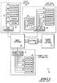
- FIG. 1illustrates a conventional transportation electrical system 10.
- System 10contains, by way of example, a body system 12, a power train system 14, with a gateway connection 16 allowing selective communication between the power train system 14 and the body system 12.
- the body system 12may contain any number of sub-systems configured as discussed above. Three specific sub-systems are illustrated in FIG. 1 as the air bag system 18, the heating ventilation and air conditioning (HVAC) system 20, and a power seat system 22.
- HVACheating ventilation and air conditioning
- the air bag system 18comprises an air bag controller 24 for monitoring all sensors within the airbag system 18 and for controlling all actuators within the system 18.
- Airbag controller 24is coupled to four, generic airbag actuators 26. Since each actuator 26 is generic, if all actuators 26 are coupled together on a common communication bus, a particular actuator 26 can not be uniquely selected to the exclusion of all other actuators 26. To overcome this, unique and exclusive line(s) are coupled between the airbag controller 24 and each actuator 26. By using separate conductive lines, the airbag controller 24 can control each actuator 26 independently of all other actuators 26. Also within system 18, airbag controller 24 is directly coupled to two, generic collision sensors 28.
- the airbag system 18requires a significant amount of wire for connection between the airbag controller 24, the actuators 26 and the sensors 28. This extensive amount of wire increases the cost of manufacturing and the weight of an automobile.
- the interconnect density available within a system, such as an automobile chassis,may prohibit such extensive wiring.
- New designsmay require significant hardware changes, making reuse of the design difficult.
- a new design which adds functionality, such as additional sensors or actuators,may exceed the available pin count of the controller 24; adding additional pins would increase the cost of the controller 24.
- the system 10also includes a distributed command and control system, HVAC system 20.
- HVAC system 20includes an HVAC controller 30 and five actuators/sensors 32A, 32B, 32C, 32D, and 32E, connected to a common communication bus 33.
- the actuators/sensors 32A, 32B, 32C, 32D, and 32Eare distinguished from each other, i.e. not identical. This may be done by using sockets which are physically or electrically distinct from each other, e.g., each socket may have different address pin connections, so that each of the actuators/sensors 32A-32E may be assigned a different address.
- socketswhich are physically or electrically distinct from each other, e.g., each socket may have different address pin connections, so that each of the actuators/sensors 32A-32E may be assigned a different address.
- actuators/sensors 32A-32Emay be electrically programmed before assembly so that each of actuators/sensors 32A-32E has a different address.
- actuators and sensors 32A-32Eare no longer generic, five separate components must be tracked, stored, and coordinated by a transportation manufacturer. Therefore, the methodology illustrated in HVAC system 20 adds additional costs to the manufacturing process, and increases the risk of an improperly functioning HVAC systems via additional chance of human error. Repair, replacement, and redesign of systems containing these multiple different components is also more onerous.
- FIG. 1also illustrates a control and command system power seat system 22 which has a power seat controller uniquely coupled through separate lines to a plurality of generic actuators 36.
- a control and command system power seat system 22which has a power seat controller uniquely coupled through separate lines to a plurality of generic actuators 36.
- there are many subsystems and electrical architectures within any transportation designwhich could be optimized to reduce cost, reduce interconnection complexity, reduce weight, increase flexibility, reduce possibility of human error, and generally improve the overall performance of automobile electrical systems.
- the present inventionis a method for interconnecting a plurality of generic nodes into a communication bus structure where the nodes are integrated circuits (ICs) and components, including CPUs, sensors, actuators, switches, or any other electrical, optical, or electromechanical device suitable for a transportation application.
- ICsintegrated circuits
- a main node or CPU of the systemprovides a unique address to each generic node. This addressing is done after assembly, in spite of the nodes being generic when first assembled into the system.
- the method and architecture discussed hereininterconnects generic nodes in a tree structure (FIG. 2).
- Another embodimentinterconnects generic nodes in a ring structure (FIG. 3).
- the present inventionprovides a method for distinguishing each of the generic nodes, where all nodes are interconnected along a single communication bus.
- each of the actuators 32were either electrically programmed or physically interconnected so as to distinguish one actuator from another actuator in system 20.
- the airbag system 18 of FIG. 1illustrates an alternative method of differentiating generic nodes.
- each generic actuator 26is uniquely addressed by an exclusive connection to central controller 24.
- this interconnection schemesignificantly increases the cost of the system, increases the interconnection density within an automobile.
- the system and method discussed hereinbelowconnects a plurality of generic nodes together on a same communication bus.
- the connectionsare made at the point of physical assembly.
- the methoddetermines a distance for each node with respect to a main node.
- the determinationmay involve a measurement of voltage potential, current, optical measure, thermal measure, resistivity, or a change in a parameter, along the communication bus length to determine a distance of each node from a main node.
- the distributed control systemhaving a control unit and at least one node coupled to a common communication bus, the distributed control system having a predetermined topology, when each node is a unique distance measured from a central controller along a communication bus, then that distance information provides a unique identifier.
- the method of initializing addressesincludes determining a distance from the control unit to each node, the distance representing a relative location of said node in the predetermined topology; and assigning a specific address to said node based on the relative location of said node in the predetermined topology.
- a measurementis made at each node and the measurement information is stored.
- the main nodeassigns an address to each node based on the measurement information.
- the measurement informationmay be adjusted to correct for errors.
- a subsystem having a plurality of generic nodes, such as those often used in transportation applicationsis designed using a single communication interconnecting generic nodes.
- FIG. 2illustrates one type of distributed system having generic nodes which can be used in accordance with the present invention.
- the network of FIG. 2is referred to as a tree network since the communication bus 41 is a single length of wire that does not close in on itself.
- FIG. 2illustrates a main node 40 which may be an electronic control unit (ECU), a digital signal processor (DSP), a microprocessor, a microcontroller unit (MCU), a custom integrated circuit or any like central processing unit (CPU) or combination thereof.
- the main nodecontrols the operation of the nodes 42 and coordinates communication among the nodes 42.
- the nodes 42are all generic components, that are coupled to the central communication bus 41.
- nodes 42are purchased as identical function parts.
- the central communication bus 41may operate using any communication bus protocol containing one or more conductive lines, but preferably operates according to a transportation communication bus standard.
- the nodes 42are generic devices that are indistinguishable from each other except for their position along the physical length of the communication bus 41. Note that it is possible to have multiple types of nodes along a single communication bus.
- the functionality of each of the nodes 42 within the systemis determined by their position. For example, if an airbag system is configured as illustrated in FIG. 2, then each of nodes 42 may be an actuator at a specific location. In this case, the node 42 positioned in the driver's side airbag responds to a different stimulus than the node 42 positioned in the steering wheel airbag.
- the nodes 42can be actuators, such as squibs used to fire airbags or electric stepper motors, sensors such as accelerometers or pressure transducers, communication devices, other microcontrollers (MCUs), DSPs, switches, or other nodes along any interconnected network.
- actuatorssuch as squibs used to fire airbags or electric stepper motors
- sensorssuch as accelerometers or pressure transducers
- communication devicessuch as communication devices, other microcontrollers (MCUs), DSPs, switches, or other nodes along any interconnected network.
- FIG. 3illustrates an alternate distributed system, referred to as a ring configuration, having a main node 31 connected to a communication bus 43 to form a ring.
- a plurality of generic nodes 42are then coupled to the communication bus 43 as illustrated in FIG. 3.
- the main node 31is a central controller or some intelligent device that controls the operation of nodes 42 and/or monitors the nodes 42.
- the nodes 42are all generic devices with the exception that their physical placement onto the communication bus 43 is different for each node 42. Note that it is possible to have multiple types of nodes along a single communication bus. For example, it is foreseeable that actuators and sensors will be configured along a single communication bus.
- the generic nodes 42can be uniquely tagged or uniquely identified by discovering and utilizing their position, distance, or proximity along either the communication bus 41 or communication bus 43. As long as no two nodes are the same distance from the main node 40 and 50 along the respective communication buses 41 and 43, each node 42 can be individually identified and individually provided with a unique address so that each generic node within the systems of FIG. 2 and FIG. 3 can be uniquely and individually accessed to the exclusion of all other nodes. Furthermore, this address and the location of the node 42 in the system is typically associated with the function of that device in transportation applications. For example, the driver front airbag is probably the closest device to that main node 31 when the node 31 is located in the driver side of the dashboard.
- the collision sensor in the rear of the vehicleis probably farthest from this main node 31 within the driver side dashboard. Therefore, by knowing the topography of the design, the main node 31 will understand that the closest node it finds is to be addressed as the driver front air bag, and the farthest node it finds should be addressed and used as the rear collision detector for example. In summary, the distance of the node can be easily correlated to the function of that node if the main controller knows the layout or topology of the transportation communication bus design.
- FIGs. 4-10will illustrate: (1) how the designs of FIGs. 2-3 can determine the placement of generic nodes along one or more of the communication buses 41 and 43; and (2) how to assign the generic nodes unique addresses that indicate their function after their distance on the communication bus is determined.
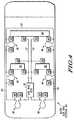
- FIG. 4illustrates an automotive airbag electrical system 50 as it is physically placed around the chassis of an automobile.
- FIG. 4illustrates the airbag electronic control unit (ECU) 52 which is analogous to the main nodes 40 and 50 of FIGs. 2 and 3 respectfully.
- the airbag ECU 52 of FIG. 4is coupled to one ring communication bus 53, as illustrated in FIG. 3, and two tree communication bus systems 55 and 57, as each are illustrated in FIG. 2.
- the ring communication bus 53first interconnects to two actuators 54 which are analogous to the nodes 42 of FIGs. 2 and 3.
- the first two actuators 54 in FIG. 4will control the deployment of a passenger front airbag.
- the two actuators 54are used to operate a single airbag, where according to one embodiment, one triggers the air bag in response to a low speed collision while the other or both actuators are utilized in higher speed collisions.
- these actuatorsare separated by a wire loop 58.
- any number of actuators 54are similarly separated by a wire loop 58.
- the loop of wire 58adds length to the communication bus 53 to effectively increase the distance between the two closely spaced actuators 54; in this way the distance from ECU 52 to each node can be accurately measured and distinguished by ECU 52.
- Each actuator 54may then be uniquely identified by a unique distance that is well outside the distance detection error of the electronic system incorporated within ECU 52. It has been experimentally determined, using current technology, that the loops 58 should ensure that at least roughly fifteen centimeters of wire separate any two adjacent communication bus-coupled actuators. This separation allows each actuator to be positioned having a unique distance from the controller; each actuator position is then uniquely discernible from all other actuator positions along communication bus 53.
- Other embodiments and other systemsmay incorporate any length of wire which allows each node to be distinguished, i.e. provide a minimum actuator to actuator distance greater than the error of the measurement and operation of the controller.
- two actuators 54 separated by a loop of wire 58are located at a middle top portion of FIG. 4 and control one or more side airbags for the front passenger portion of the car.
- two actuators 54, separated by another loop of wire 58are used to control a side airbag for a fight rear passenger.
- the communication bus 53couples to two actuators 54 separated by a loop 58 which will control one of more airbags for a left rear passenger.
- two or more actuators 54 and a loop of wire 58 between each closely spaced actuatorwill allow for control of a driver side airbag.
- two final actuators 54 and another loop of wire 58are used to operably couple the final two actuators to enable control a driver front airbag.
- the actuators 54, the loops of wire 58, and the ring communication bus 53implement a ring communication bus architecture as illustrated in FIG. 3.
- FIG. 4also illustrates tree communication bus structures 55 and 57, which are each coupled to the airbag ECU 52.
- the communication bus 55controls a seatbelt pretensioner actuator 54 on both a front seat 56 and a back seat 56 and a front airbag for a left side back seat passenger.
- a tree communication bus structure 57also controls two seatbelt pretensioner actuators 54 for the front seat 56 and back seat 56 as well as a second front airbag for the right side back seat passenger.
- These tree structures 55 and 57are similar to the general tree structure illustrated in FIG. 2.
- the airbag ECU 52will uniquely determine a position of each actuator 54 on the communication bus 53.
- the selective positioning of loops between actuators 54provides additional distance between actuators which are spaced too closely to distinguish one from the other.
- ECU 52has information regarding the predefined topology of the system.
- ECU 52assigns addresses to each actuator 54 based on its distance from the airbag ECU 52. Note that according to one embodiment, the distance is measured unidirectionally.
- each actuator 54can be individually addressed, controlled, diagnostically tested, and monitored by the airbag ECU 52. The same is true for all actuators 54 along the tree communication buses 55 and 57. Once each actuator is uniquely located along a distance of these communication buses 55 and 57, the actuators 54 on these communication buses can be uniquely provided with a unique address and uniquely identified for subsequent operation, monitoring, and diagnostic servicing.
- the automotive airbag application illustrated in FIG. 4is an exemplar of a distributed command and control system incorporating the present invention. Both ring type and tree type systems are considered. Alternate embodiments may utilize the a combination of these types or may implement some other type of command and control distributed format.
- FIG. 5shows a more detailed illustration of a tree communication bus structure 55 or 57, including nodes 54 and ECU 52 of the air bag electrical system 50 of FIG. 4. More specifically, the air bag ECU 52 of FIG. 5 contains an ECU communication unit 59 and a current and voltage supply unit 58, each coupled to common bus 55.
- the current and voltage supply unit 58is used to identify the distance of each node 54 along the communication bus interconnection 55 or 57.
- the ECU communication unit 59will then provide a unique address to each node 54 on the common bus 55.
- control information, monitoring information, and diagnostic informationcan be uniquely tagged and communicated to individual nodes 54 connected to the common bus 55, even though each node 54 attached to common bus 55 was an indistinguishably generic structure to all other nodes 54 when first installed into the transportation system.
- each node 54 in FIG. 4 and FIG. 5includes a communication circuit and an error checking circuit 60, such as a cyclical redundancy code (CRC) check unit.
- Each nodealso contains a node address initialization unit 61, and a squib control unit 66.
- the communication circuit unit 60will allow information to be communicated bidirectionally between the node 54 and the ECU communication unit 59 as previously discussed.
- the communication circuit unit 60can provide derived digital serial distance data to the ECU communication unit 59.
- the communication circuit unit 60will receive and properly route the unique address communicated from the ECU communication unit 59 to the node 54 in response to its communication of its distance data.
- the communication circuit 60generally has a serial shift register for capturing addressing bits, a serial shift register for data capture once properly addressed, and a data register for providing serial data output to the communication bus (may be same as data capture register).
- an error checking circuitsuch as that illustrated with communication circuit 60, or a CRC check or any other type of error detection and/or correction circuit is used to ensure that errors in the transmission between the air bag ECU 52 and a node 54 do not result in erroneous operation of the air bag safety system (e.g., triggering of the air bag when there is no accident).
- the analog distance determination circuitry 61contains a controller 62, random access memory (RAM) 68, nonvolatile memory portion 70, an analog-to-digital (A/D) converter 64, and a voltage regulator 72.
- the controller 62generally controls the operation of the node 54 (e.g., whether the node is in the normal mode of operation or the initialization mode of operation).
- the controller 62informs the A/D converter 64 that the initialization mode of operation is beginning.
- the current and voltage supply unit 58will provide voltage and/or current signals along the communication bus 55 which will allow the A/D converter 64 to derive certain digital values over time.
- the connector 74is temporarily coupled to the communication bus 55 to short circuit or "close-loop" the communication bus for the current-driven distance determination of the initialization process (see FIG. 7).
- These certain digital valuesare provided to the RAM 68 via the controller 62. The specific determination and provision of these digital values and their significance to determining the distance on the communication bus 55 are discussed in more detail with respect to subsequent FIG. 7.
- the controller 62will then provide these distance values back to the ECU communication unit 59 via the communication circuit 60.
- the ECU unit 52Once the ECU unit 52 has received all of the distance information from all of the units 54, the ECU 52 will then provide addresses from the unit 56 to all of the controllers 62 within each node 54 of the system of FIG. 5.
- Each node 54will be uniquely tagged by the ECU communication unit 59 during this unique address provision operation by using the distance values that the controller 62 previously stored into RAM 68 as a unique identifier. In other words, each node 54 within the system of FIG.
- the ECU communication unit 59will provide a unique address value which the communication circuit 60 only of that selected node 54 will accept. That controller 62 will provide the respective unique address to the nonvolatile memory portion 70 of FIG. 5.
- Each of the nodes 54are serially provided with a unique address in this manner.
- the nonvolatile memory 70is one or more of ferroelectric embedded DRAM, electrically erasable programmable read only memory (EEPROM), or like nonvolatile storage devices.
- EEPROMelectrically erasable programmable read only memory
- the A/D converter 64is informed by the controller 62 to deactivate, and the entire system of FIG. 5 is now capable of entering a normal mode of operation with full addressing capability.
- the ECU communication unitcan provide packets of information containing an address, data, and error checking information to the communication bus. Only the single node 54 which is uniquely tagged by the packet as can be determined by comparing the packet address to the nonvolatile memory contents will process the data information. Therefore, every generic node 54 within the system of FIG. 5 can be uniquely tagged by using the architecture illustrated in FIG. 5.
- FIG. 5illustrates the tree structure of communication buses 55 and/or 57 of FIG. 4
- FIG. 6illustrates the ring structure of communication bus 53 from FIG. 4.
- FIG. 5relies on an externally attached connector 74 in order to short the communication bus 62 of FIG. 5 in order to perform current-based distance detection operations.
- a switch unit 76is used in air bag ECU 52 in order to close the loop on the communication bus 53. Closed loop operation is needed within the system during the initialization period as will become evident after the discussion of FIGs. 7-8.
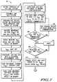
- FIGs. 7-8illustrates a interconnected flowchart which teaches a methodology to initialize the structures of FIGs. 5 and/or 6.
- FIGs. 7-8illustrates a technique by which voltage and current processing can be used to identify a physically unique distance of each node 54 along a communication bus structure 53 or 55. Once this distance is determined for each node 54 by the nodes themselves, the distance value(s) are communicated from the nodes 54 to the air bag ECU 52. This distance information is processed by the ECU 52 whereby each unique distance is assigned to a unique address. These unique addresses are then provided to each node 54 where the nodes are addressed to provide these unique addresses via their unique distance information that was previously transmitted by the nodes 54.
- NVMnonvolatile memory
- the method of FIGs. 7-8begins in FIG. 7 by defining a topology of the air bag system in a step 82.
- an automotive designerwill define the number of actuators coupled to each communication bus, the type of communication bus architectures used (either ring or tree or both), and the function of the actuators on each communication bus according to the actuator's position/distance along the communication bus length (e.g., the closest actuator is a front air bag, a middle actuator is a front seat pretensioner, and a farthest actuator on the communication bus is a collision accelerometer to detect an auto accident).
- Defining the topology before assembly, initialization, and operation of a transportation systemis important since certain parameters of the software within the ECU 52 must be programmed according to the topology in order to enable proper initialization and operation. For example, for initialization purposes, it may be advantageous for the ECU 52 to know exactly how many nodes 54 are attached to its communication bus. Once the specific number of nodes attached to the communication bus is understood, the ECU 52 can perform more efficient initialization operations without missing the address initialization of some important nodes. Furthermore, once the ECU 52 determines that there are N nodes rank-ordered in distance from 1..N, it would be useful for the ECU 52 to know what function is performed by each actuator in each relative position.
- step 84will assemble the actuators 54, main node ECU 52, and wiring into an electrical system as illustrated in one or more of FIGs. 2 through 4.
- step 86the ECU is programmed in accordance with the topology of step 82 to allow for efficient initialization and operation of the system as previously discussed.
- the ECU 52may be told that there are six actuators in the communication bus system wherein the two closest actuators are the front passenger air bags, the next two closest actuators are side air bags and the last two closest actuators are seat belt restraint devices for the back seat. Knowing the number of actuators in the system and their desired operation as a function of distance along the communication bus will allow the ECU to perform efficient and correct initialization operations on these generic actuators.
- poweris provided to all of the actuators, communication buses, and ECU devices within the system via step 86.
- step 88the current and voltage supply 58 within FIGs. 5 or 6 will provide a reference voltage (Vref) along the respective communication bus 53 or 55 that requires initialization.
- Vrefa reference voltage
- the connector 74 of FIG. 5is not attached to the system and the closed circuit unit 76 of FIG. 6 is controlled so that the end of the ring communication bus 53 in FIG. 6 is disconnected.
- the reference voltage provided in the communication busshould be the same voltage provided to all of the nodes 54 within the system, assuming no significant current loss due to leakage current (which is a safe and accurate assumption for the method of FIG. 7). With little or no leakage currents, the voltage V1 and the voltage VN respectively across all N of the nodes 54 coupled within the systems of FIGs.
- each A/D converter 64 and each voltage regulator 72 within each nodeis an imperfect mismatched analog device.
- the A/D converter 64 and the voltage regulators 72will vary from node-to-node, will vary with different temperatures, and will have inherent nonlinearities which may render each node 54 slightly different from all other nodes 54.
- the reference voltage (Vref)is used in the methodology of FIG. 7.
- step 90 of FIG. 7stores a digital Vref value into RAM location 68 of each node or distance error correction purposes.
- a step 92will signal the end of the Vref recordation phase, e.g. by shutting off the supply of the voltage reference signal from the current and voltage supply 58.
- This Vref termination periodis performed to communicate to all the nodes 54 that the digital Vref recordation portion of the initialization algorithm has terminated.
- enough timeis provided in step 90 to ensure that all nodes 54 have adequately processed and stored a digital Vref value before Vref is shut off in the step 92.
- the air bag communication bus 53 and/or 55is configured to perform a distance loop measurement using a sourced current provided as output from the current supply 58.
- the required closed loop configurationis enabled by providing a connector 74 across the communication bus 62 to short both signals of the communication bus 62 together to form a loop structure.
- Connector 74may be as simple as a resistive device or loop of wire, but 74 may also contain sophisticated diagnostic electronics. If more than two communication bus signals are provided, the loop need only close circuit any two signals (e.g., power and ground, signal and ground, signal and power, etc.) that connect to each and every node on the communication bus).
- step 7is accomplished by informing the circuitry within unit 76 to short both signals of the ring communication bus 53 together with one another through an optional resistance device. Therefore, in step 94, one of either the externally attached connector 74 or the internally controlled unit 76 forms a closed loop connection on its respective communication bus structure.
- the current and voltage supply unit 58will communicate a fixed reference current (I) unidirectionally through the closed loop communication bus 53 or 55 in one or more of FIGs. 5 and 6. Since the communication bus has a resistance value per unit length, the resistance experienced by each node via the communication bus connection is linearly proportional to the distance of wire connected between the unit 58 and the node 54. In other words, nodes 54 that are closer to the current and voltage supply unit 58 along the communication bus 53 or 55 will experience a different voltage than those nodes positioned far away from the current and voltage supply unit 58. As a specific example, the voltage V1 in FIG.
- Vdistthe node's respective distance voltage or Vdist. Any of the nodes lying between the closest node 54 and the farthest node 54 will have some different Vdist voltage value proportional to communication bus distance where Vdist is somewhere between the high and low values of 100mV and 15mV for the above example.
- a step 98the controller 62, in response to the signaling from steps 92-94, waits for a settling time and then informs the analog to digital converter 64 in its respective node 54 to record the converted value of this analog distance voltage (Vdist) and store the resulting digital distance voltage (Vdist) within the RAM 68 along with the previously stored digital Vref value. Therefore, the node 54 closest to unit 58 will store a digital Vdist value analogous to 100 millivolts in the RAM 68 whereas the farthest node 54 within the system will record a digital Vdist value analogous to 15 millivolts within its RAM 68. Note that two closely-coupled adjacent nodes along the communication bus may differ in Vdist only by a few millivolts.
- the nonlinearity, process differences, and like inherent variations between the analog circuitry in the nodes 54may result the closest node reading 50mV and the farthest node reading 51mv erroneously (remember that in the specific embodiment of FIGs. 5-6 that the closer node should have a greater Vdist than the farther node).
- this error in Vdistcan be quantified by the Vref values where the Vref values may be used to "correct” any erroneous Vdist values into their "true” or "corrected Vdist values.
- each node 54will be uniquely identified by the ECU communication unit 59 since no two nodes will have the same Vdist and Vref values.
- the combination of the Vref and the Vdist values within the nodes 54will allow the ECU unit 56 to accurately organize the nodes 54 in accordance with their respective distances along the communication bus and will allow the ECU unit 56 to uniquely identify each node in the system.
- the Vref and Vdist valuesmay be processed by the individual nodes to create a unique processed value wherein these unique processed values become the unique address for each node. The ECU may then be told what the addresses are once the nodes assign the unique addresses to themselves.
- the Vdist and Vref valuesare communicated to the more powerful ECU 52 so that the ECU can mathematically process the Vdist and Vref values and provide a unique address to each node using a recommunication of the Vdist and Vref values as a unique node identifier. This second form is further illustrated in the remaining steps of FIG. 7.
- step 100commences.
- the connector 74 of FIG. 5is removed from the communication bus 55 and/or the unit 76 of FIG. 6 is disabled to return the communication buses 53 and/or 55 to the normal open loop configuration.
- the current and voltage supply 58is disabled and decoupled from the communication bus 53 and/or 55 in step 100.
- the air bag communication busis converted back to a normal configuration to allow each node 54 to communicate the Vdist and Vref values from each of the RAMs 68 to the ECU communication unit 59 via the communication circuit 60 in each node 54.
- communication circuit 60may include a serial communication unit or any other type unit adapted for communication on a common bus.
- step 102each node sets a random time at which to begin transmitting the Vdist and Vref values from its RAM 68 to the ECU communication unit 59.
- each node 54waits a random amount of time that likely different for each node, and then provides the Vdist and Vref values from the RAM 68 to the communication circuit 60 via the controller 62.
- each nodesets a random time in a counter and times out the counter using this random time (note that each random time should statistically be different in all nodes most of the time, however, when two times are too close, equal or overlap, collisions can be compensated for using the techniques outlined below).
- that specific node's communication circuit 60will begin providing the Vref and Vdist information serially to the ECU communication unit 59.
- the ECU communication unitwill use CRC check sum processing on all information provided from each node 54 to ensure proper receipt of the Vref and Vdist information for each node 54.
- the node 54itself can determine if the information was properly communicated by monitoring the communication bus 53 and/or 55 for communication bus contention via the communication circuit unit 60. If the communication circuit 60 of the transmitting node 54 senses no communication bus contention and the ECU communication unit 59 performs proper CRC check sum calculations, then the information was properly communicated from that node 54 to the communication unit 59 in step 102 and no retransmission is needed for initialization.
- the ECU communication unit 59 and the communication circuit unit 60are constantly checking the communication bus 53 and/or 55 for communication bus contention during step 106. If one or more nodes 54 detect a collision during transmission of the Vref or Vdist values, then each of the nodes which experience a collision will generate another random delay time (see step 104) and then attempt to recommunicate their Vdist and Vref information once again after that additional random interval has expired.
- the ECU communication unit 59understands the topology of the system as defined in step 82. Therefore, the ECU communication unit 59 knows how many nodes 54 are in existence on the communication bus 53 and/or 55. Therefore, the ECU communication waits the proper random time period until all combinations of the Vref and Vdist values for all N nodes are properly received. If the ECU 52 receives less than N correct transmissions for the system, then noise may have causes a failure without a node noticing the communication bus contention or error whereby retransmission of all nodes must commence again until all N nodes are received in any random order without CRC error.
- steps 108 and 110are performed by the ECU communication unit 59 until all N pairs of valid Vdist and Vref information is entirely received by the unit 56. Once all N Vref and Vdist pairs are received for all N nodes 54 within the system, a step 112 is performed in FIG. 7.
- step 112mathematical computations are performed by the unit 56 using the Vdist and Vref values in order to remove voltage variation, performance variation, process variation, A/D nonlinearity, and other erroneous and/or inherent errors/differences from the original Vdist data to result in corrected Vdist data.
- step 114is performed in FIG. 8.
- the ECU communication unit 59will sort all of the corrected Vdist values by magnitude from greatest to least or from least to greatest. Since the ECU communication unit 59 was informed of the topology of the system in step 82, the air bag system knows which device is supposed to be the closest device in the system and the function it performs, which device is to be the next closest device in the system and the function it performs, and so on until the last closest device in the system is identified by position and function.
- the ECU 52can determine which nodes 54 are to get which addresses (see step 116), and the unit 52 can determine the function that is performed by each addressed node 54 in the system given its distance along the communication bus 53 and/or 55.
- a step 116is performed in FIG. 8 to assign unique addresses to each node 54 according to function and/or distance.
- the ECU communication unitserially communicates the Vref and Vdist pairs of values out along the communication bus 53 or 55. These Vref and uncorrected or original Vdist values are captured by all the communication circuits of all the nodes 54. Only one node 54 among all the nodes 54 will have received Vref and uncorrected Vdist values that matches the information it has previously stored in its RAM 68 (see step 120). This one node 54 is then on notice by its controller 62 that it must receive the following transmitted unique address to the exclusion of all other nodes 54.
- a unique addressfollows the uncorrected Vdist and Vref information, and only that one node 54 which is identified by the Vdist and Vref values will accept the unique address via its communication circuit 60 (see step 122).
- a step 122only the nonvolatile memory 70 of the selected node 54 is written with the unique address.
- the steps 118 through 124are repeated N times until all N unique addresses are properly sent and CRC checked to all N nodes connected to the respective communication bus. Any nodes that experience a failure in the address CRC operation may communicate to the ECU 52 its Vref and Vdist information once again at a later time to flag such an error to the ECU 52. Once the CRC error is flagged for that one node 54, the ECU may transmit the unique address once again (along with Vref and the original Vdist as needed) until all unique addresses are properly stored in NVM 70 by the nodes 54. After all of the units 54 have been provided with a unique address with proper CRC checking, the unique address is respectively stored in the nonvolatile memory 70 of each node 54. After NVM storage of the unique address, normal mode of operation may begin whereby the transportation system can use the ECU unit 56 to uniquely identify any of the generic nodes 54 within the subsystem for operation, later re-initialization, diagnostic monitoring, and the like.
- FIG. 9illustrates an alternate embodiment to the 10 communication bus structure illustrated in FIG. 5. All of the elements in FIG. 5 and FIG. 9 that are generic or substantially similar in structure and/or function are indicated by generic reference number.
- One primary difference between a FIG. 9 and FIG. 5is that the current and voltage supply 58 of FIG. 5 is replaced with a current ramp supply 134 in FIG. 9.
- the externally attached connector 74 of FIG. 5is replaced with a much more complicated externally-attached reference voltage source (Vref) 136.
- Vrefexternally-attached reference voltage source
- the analog distance determination circuitry 61 of FIG. 5is different from the node address initialization unit 135 of FIG. 9. In FIG.
- the unit 61utilizes an A-D converter 64 during initialization in order to uniquely determine a physical position or distance of the node 54 along the length of the communication bus 62.
- a peak and hold unit 132replaces the voltage regulator 72 in the A-D converter 64 of FIG. 5.
- a sample and hold unitmay be implemented.
- each node 154will store a trigger voltage within a capacitor in the peak and hold unit 132 which is proportional to the reference voltage provided by unit 136. Therefore, each node 54 will store roughly the same trigger voltage within its respective unit 132.
- the current ramp circuitry in circuit 134will begin to ramp the current from zero amps up to some predetermined amperage level. Since the resistive length of communication bus exposed to each node 54 is different, the differential voltage values V1 through VN across each node 54 will change at a different rates as the current linearly ramps. In other words, nodes experiencing more communication bus resistance length will change in voltage faster and those nodes experiencing less communication bus resistance whereby the voltages V1 through VN across the nodes will begin to diverge/spread as the current ramp progresses. In one embodiment, the voltage V1 will reach the trigger voltage before any of the other node voltages V2-VN reaches the trigger voltage.
- the peak and hold unit 132will notice that the trigger voltage was reached for this first V1 node 54 and notify the controller 130 of this event.
- This controller 130 of the first V1 node 54will then send a signal to the ECU.
- One method to send thisis to short the communication bus 62 through the communication circuit unit 60 whereby the ECU communication unit 59 will sense the electrical short-circuiting change on the communication bus.
- the current ramp operations via the unit 134will cease and the ECU communication unit 59 will transmit a unique address value to the selected V1 node 54 for storage in its non-volatile memory location 70.
- the controller 130 of that selected node 54will terminate its peak and hold unit connection to the communication bus and cease participation and any further current ramp operations.
- the next current ramp operationis then progressed with the most-recently programmed node and all previously address-programmed nodes not participating in the ramp operation.
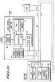
- FIG. 10illustrates a system analogous to FIG. 9 in operation, but FIG. 10 uses the ring configuration of FIG. 6 instead of the tree configuration of FIG. 9.
- the voltage reference source unit 136is moved on chip with the current ramp circuitry 134.
- the communication bus 60then forms a ring between the current ramp circuit 134 and the voltage reference source unit 136.
- the systems of FIGs. 9 and 10are very similar in structure and very similar in methodology. Therefore, the discussion of FIG. 9 will generally apply to the discussion of FIG. 10 with the unit 136 being internally controlled by the ECU 52 instead of being externally controlled as in FIG. 9.
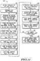
- FIG. 11illustrates a method of operation which may be used in accordance with the systems of FIGs. 9 and 10 when used in the transportation application shown in FIG. 4.
- the steps 202-206are analogous and substantially similar to the steps 82-86 of FIGs. 7-8.
- a step 208will enter the initialization mode and provide the reference voltage (Vref) on the airbag system communication bus via the unit 136.
- Vrefreference voltage
- no currentis flowing along the communication bus whereby every node 54 should be receiving the same reference voltage, assuming leakage current is negligible.
- all of the nodes within the systems shown in FIGs. 9 and 10will store a trigger voltage that is a function of the reference voltage (Vref) across their terminals. This trigger voltage is stored within a capacitor or like element/system in the circuit 132.
- a step 212will signal the end of the Vref storage phase, e.g. by shutting Vref off to signal to the nodes 54 that the next stage of initialization is to begin.
- a step 214the Vref voltage from the unit 136 is turned back on and the current output from the unit 134 is ramped from no current to some maximal initialization current in a step 216 until a trigger event is detected.
- the presence of the fixed voltage 136 and the changing of the current 134will ensure that the differential voltages across each and every node 54 will change at different rates since these nodes are located at different positions on the resistive communication bus interface.
- each nodeis constantly comparing the voltage across their differential inputs with the previously stored trigger voltage that is a function of the Vref voltage in a step 218. Since each node 54 is subject to a different resistance from the communication bus the current ramp will push the differential input voltage of one node V1 - VN to the trigger point before all others. Therefore, due to the current ramp, one selected node 54 will reach the stored trigger voltage within the peak and hold unit 132 before all other nodes 54 reach this value.
- This selected nodewhich can be engineered as being the closest node or the furthest node from the ECU 52 depending upon placement of the units 134 and 136 in the system, is the selected node in step 220 of FIG. 10.
- the controller 130 of the selected node 54will short circuit the communication bus via its respective interface 60.
- the ECU 52will detect this short circuiting of the communication bus and reconfigure the airbag system communication bus to a normal configuration in the step 222.
- the controller of the selected nodewill configure the communication circuit to receive a unique address whereas all of the other untriggered nodes 54 will ignore any address communication.
- the step 224 of FIG. 10then provides the unique address from the ECU communication unit 59 to the one triggered node 54 in the system. This unique address is only accepted by the one triggered/selected node 54, and the unique address is stored in the selected node's respective non-volatile memory 70.
- step 226the selective node is removed from its initialization state and the peak and hold circuit 132 of such selected node 54 is decoupled from the communication bus and will participate in no more current ramp operations.
- the address programmed nodeswill ignore any communication bus operations (i.e., the ramp initialization operations and all other operations) until the ECU 52 sends an "initialization done" data packet sequence to all nodes 54 on the communication bus. Note that if the address communication to the selected node 54 fails due to CRC failure detected in the selected node's unit 60, then the selected node 54 can notify the ECU 52 of such event by shorting the communication bus.
- an acknowledgmentmay be sent from unit 60 once receipt is complete and proper, and if no acknowledgment is initiated by unit 60, then the information may be resent within the system.
- a step 228, the ECU communication unit 59which knows the topography of the system from step 206, determines if any other nodes in the system remain unaddressed. If nodes remain unaddressed, the steps 208-228 are repeated until each and every node 54 within the system is sequentially triggered and serially provided with a unique address from the ECU 52. Once the last node 54 within the system is provided with a unique address where all CRC values show no errors, the normal node of operation is entered via a step 230 of FIG. 10 whereby each node 54 is "awakened” from its "ignore initialization" state by a start data packet sent out by the ECU 52 along the communication bus. All the nodes 54 in the system of FIGs. 9-10 are now responsive to a unique address within the system.
Landscapes
- Engineering & Computer Science (AREA)
- Computer Networks & Wireless Communication (AREA)
- Signal Processing (AREA)
- Physics & Mathematics (AREA)
- General Physics & Mathematics (AREA)
- Automation & Control Theory (AREA)
- Small-Scale Networks (AREA)
- Air Bags (AREA)
Abstract
Description
The present invention relates generally to distributedcommand and control systems for use in transportation, andmore particularly to, a process for assigning unique addresses toeach generic "node" in a distributed control system that containsa plurality of generic nodes coupled to the same distributedcommunication bus.
In the transportation industry, a common problem is that adistributed communication bus system may be electricallyconnected to many generic nodes. When a distributedcommunication bus interconnects many generic nodes, it isdifficult to assign a unique address to each node within thedistributed system. Due to the difficulty of uniquely addressingmany generic nodes intercoupled together, many electricalsystems within transportation applications individually programeach node or component before placement within the system. Bychanging each IC or node before placement into the system, eachnode can be uniquely identified easily, but such advantage comes at a cost. When devices are programmed with an addressbefore assembly, human error may result in the improperplacement of a device programmed as "Device A" into animproper location intended for a "Device B" whereby faultyoperation can occur. This faulty operation may not be capable ofeasy and cost-effective testing, as is the case for the testing ofairbag systems in an automobile. In addition, the overhead forkeeping track of individually addressed parts before assemblycan be cumbersome. For example, assume that sixteen genericparts are desired in the same communication bus system. Ifthese sixteen parts are generic, then all sixteen parts may becatalogued, stored, and used as one interchangeable part. If anindividual tag must be applied to each of the sixteen genericparts, then the process of storing, reusing, repairing, replacing,and assembling the systems becomes much more cumbersomeand prone to human error.
As an alternative to uniquely tagging parts before assembly,one may use uniquely configured sockets or physicalinterconnects for the parts to make each generic part uniquelyidentifiable. While different in form from the above pre-programmedsolution, the disadvantages and risks are the same.
Alternatively, a distributed communication bus system maybe avoided in favor of a point-to-point communication systemwhere each of N nodes is directly coupled to a central controllerby a respective one of N different and mutually exclusiveconductors. This ensures that each node can be uniquely accessed; however, there are many disadvantages to thisapproach. These N conductive interconnects can quickly becomecumbersome within a transportation design, and the costs ofsuch design may be prohibitive. The added interconnection ofadditional wire will significantly add to the weight of the systemor automobile. The interconnection density in an automobilechassis is limited and better dedicated to other more importantfunctions. In addition, N connections may need N pins on an IC,where pin count is severely limited in many microcontroller anddigital signal processor (DSP) designs. In general, this bruteforce method of connecting unique lines to each node in thesystem is fast becoming unreasonable.
Generally, a need exists in the transportation industry, andothers, for a distributed communication bus architecture andmethodology which enables generic nodes or components to beintercoupled via a common communication bus connectionwhere unique addressing or tagging of the generic componentsis still enabled.
For clarity, the following description focuses on anautomotive embodiment of the present invention. Theautomotive embodiments considered hereinbelow are illustratedin FIGs. 1-11. The present invention is applicable to anytransportation system having a distributed control andcommand system, and is not intended to be limited toautomotive embodiments discussed herein. The method foraddress initialization of generic nodes in a distributed commandand control system of the present invention is not specific to aparticular node function, but as illustrated hereinbelow may beused to initialize any number of systems.
FIG. 1 illustrates a conventional transportationelectricalsystem 10.System 10 contains, by way of example, abody system 12, apower train system 14, with agateway connection 16 allowing selective communication between thepower trainsystem 14 and thebody system 12.
Thebody system 12 may contain any number of sub-systemsconfigured as discussed above. Three specific sub-systems areillustrated in FIG. 1 as theair bag system 18, the heatingventilation and air conditioning (HVAC)system 20, and apowerseat system 22.
In FIG. 1, theair bag system 18 comprises anair bagcontroller 24 for monitoring all sensors within theairbag system 18 and for controlling all actuators within thesystem 18.Airbagcontroller 24 is coupled to four,generic airbag actuators 26.Since eachactuator 26 is generic, if allactuators 26 are coupledtogether on a common communication bus, aparticular actuator 26 can not be uniquely selected to the exclusion of allotheractuators 26. To overcome this, unique and exclusive line(s) arecoupled between theairbag controller 24 and eachactuator 26.By using separate conductive lines, theairbag controller 24 cancontrol eachactuator 26 independently of allother actuators 26.Also withinsystem 18,airbag controller 24 is directly coupled totwo,generic collision sensors 28.
Theairbag system 18 requires a significant amount of wirefor connection between theairbag controller 24, theactuators 26and thesensors 28. This extensive amount of wire increases thecost of manufacturing and the weight of an automobile. Theinterconnect density available within a system, such as an automobile chassis, may prohibit such extensive wiring. Newdesigns may require significant hardware changes, making reuseof the design difficult. A new design which adds functionality,such as additional sensors or actuators, may exceed the availablepin count of thecontroller 24; adding additional pins wouldincrease the cost of thecontroller 24.
As shown in FIG. 1, thesystem 10 also includes a distributedcommand and control system,HVAC system 20.HVAC system 20 includes anHVAC controller 30 and five actuators/sensors HVAC system 20 is fullyassembled, the actuators/sensors sensors 32A-32E may be assigned a different address. When using thisunique socket approach, human error during assembly couldresult in a non-functionalHVAC system 20. In the alternative,actuators/sensors 32A-32E may be electrically programmedbefore assembly so that each of actuators/sensors 32A-32E has adifferent address. In this case, since actuators andsensors 32A-32Eare no longer generic, five separate components must betracked, stored, and coordinated by a transportationmanufacturer. Therefore, the methodology illustrated inHVACsystem 20 adds additional costs to the manufacturing process,and increases the risk of an improperly functioning HVAC systems via additional chance of human error. Repair,replacement, and redesign of systems containing these multipledifferent components is also more onerous.
FIG. 1 also illustrates a control and command systempowerseat system 22 which has a power seat controller uniquelycoupled through separate lines to a plurality ofgeneric actuators 36. In addition to the systems illustrated in FIG. 1, there aremany subsystems and electrical architectures within anytransportation design which could be optimized to reduce cost,reduce interconnection complexity, reduce weight, increaseflexibility, reduce possibility of human error, and generallyimprove the overall performance of automobile electricalsystems.
Generally, the present invention is a method forinterconnecting a plurality of generic nodes into acommunication bus structure where the nodes are integratedcircuits (ICs) and components, including CPUs, sensors,actuators, switches, or any other electrical, optical, orelectromechanical device suitable for a transportationapplication. A main node or CPU of the system provides aunique address to each generic node. This addressing is doneafter assembly, in spite of the nodes being generic when firstassembled into the system. According to one embodiment, themethod and architecture discussed herein interconnects genericnodes in a tree structure (FIG. 2). Another embodimentinterconnects generic nodes in a ring structure (FIG. 3). The present invention provides a method for distinguishing each ofthe generic nodes, where all nodes are interconnected along asingle communication bus.
In the prior art as in theHVAC system 20 of FIG. 1, thedifficulty in addressing generic parts was overcome by makingeach of the actuators 32 a different part before assembly. Each ofthe actuators 32 were either electrically programmed orphysically interconnected so as to distinguish one actuator fromanother actuator insystem 20. Theairbag system 18 of FIG. 1illustrates an alternative method of differentiating genericnodes. Here eachgeneric actuator 26 is uniquely addressed byan exclusive connection tocentral controller 24. However, thisinterconnection scheme significantly increases the cost of thesystem, increases the interconnection density within anautomobile.
The system and method discussed hereinbelow connects aplurality of generic nodes together on a same communicationbus. The connections are made at the point of physicalassembly. During an initialization period, the methoddetermines a distance for each node with respect to a main node.The determination may involve a measurement of voltagepotential, current, optical measure, thermal measure, resistivity,or a change in a parameter, along the communication bus lengthto determine a distance of each node from a main node.
In a distributed control system having a control unit and atleast one node coupled to a common communication bus, the distributed control system having a predetermined topology,when each node is a unique distance measured from a centralcontroller along a communication bus, then that distanceinformation provides a unique identifier. In one embodiment,the method of initializing addresses includes determining adistance from the control unit to each node, the distancerepresenting a relative location of said node in thepredetermined topology; and assigning a specific address to saidnode based on the relative location of said node in thepredetermined topology. A measurement is made at each nodeand the measurement information is stored. The main nodeassigns an address to each node based on the measurementinformation. The measurement information may be adjusted tocorrect for errors. In this way, a subsystem having a plurality ofgeneric nodes, such as those often used in transportationapplications, is designed using a single communicationinterconnecting generic nodes.
The use of a single communication bus not only reducesmanufacturing costs, but reduces interconnection density andresults in a reduced weight of the automobile. Using such adesign, the addition of new nodes to the system is easier toaccomplish. In addition, it is possible to implement the designusing generic nodes whereby parts are easier to track duringmanufacturing interchangable for repair and replacement. Inaddition, since all of the nodes connected to the communicationbus are generic, human error resulting from the misplacement ofa part into the system is eliminated. In summary, the use of a unique distance of each node to assign addresses within adistributed system offers significant advantages over the priorart. While automotive applications seem to be a first application,many other distributed systems may benefit from this technique,such as home wiring, telecommunications, etc.
FIG. 2 illustrates one type of distributed system havinggeneric nodes which can be used in accordance with the presentinvention. The network of FIG. 2 is referred to as a tree networksince thecommunication bus 41 is a single length of wire thatdoes not close in on itself. FIG. 2 illustrates amain node 40which may be an electronic control unit (ECU), a digital signalprocessor (DSP), a microprocessor, a microcontroller unit(MCU), a custom integrated circuit or any like central processingunit (CPU) or combination thereof. The main node controls theoperation of thenodes 42 and coordinates communicationamong thenodes 42. In FIG. 2, thenodes 42 are all genericcomponents, that are coupled to thecentral communication bus 41.
Typicallynodes 42 are purchased as identical function parts.Thecentral communication bus 41 may operate using anycommunication bus protocol containing one or more conductivelines, but preferably operates according to a transportationcommunication bus standard. Thenodes 42 are generic devicesthat are indistinguishable from each other except for theirposition along the physical length of thecommunication bus 41.Note that it is possible to have multiple types of nodes along a single communication bus. The functionality of each of thenodes 42 within the system is determined by their position. Forexample, if an airbag system is configured as illustrated in FIG.2, then each ofnodes 42 may be an actuator at a specific location.In this case, thenode 42 positioned in the driver's side airbagresponds to a different stimulus than thenode 42 positioned inthe steering wheel airbag. Thenodes 42 can be actuators, such assquibs used to fire airbags or electric stepper motors, sensorssuch as accelerometers or pressure transducers, communicationdevices, other microcontrollers (MCUs), DSPs, switches, or othernodes along any interconnected network.
FIG. 3 illustrates an alternate distributed system, referred toas a ring configuration, having amain node 31 connected to acommunication bus 43 to form a ring. A plurality ofgenericnodes 42 are then coupled to thecommunication bus 43 asillustrated in FIG. 3. As in FIG. 2, themain node 31 is a centralcontroller or some intelligent device that controls the operationofnodes 42 and/or monitors thenodes 42. Thenodes 42 are allgeneric devices with the exception that their physical placementonto thecommunication bus 43 is different for eachnode 42.Note that it is possible to have multiple types of nodes along asingle communication bus. For example, it is foreseeable thatactuators and sensors will be configured along a singlecommunication bus.
In FIG. 2 and FIG. 3, thegeneric nodes 42 can be uniquelytagged or uniquely identified by discovering and utilizing their position, distance, or proximity along either thecommunicationbus 41 orcommunication bus 43. As long as no two nodes arethe same distance from themain node respective communication buses node 42 can beindividually identified and individually provided with a uniqueaddress so that each generic node within the systems of FIG. 2and FIG. 3 can be uniquely and individually accessed to theexclusion of all other nodes. Furthermore, this address and thelocation of thenode 42 in the system is typically associated withthe function of that device in transportation applications. Forexample, the driver front airbag is probably the closest device tothatmain node 31 when thenode 31 is located in the driver sideof the dashboard. However, the collision sensor in the rear ofthe vehicle is probably farthest from thismain node 31 withinthe driver side dashboard. Therefore, by knowing thetopography of the design, themain node 31 will understand thatthe closest node it finds is to be addressed as the driver front airbag, and the farthest node it finds should be addressed and usedas the rear collision detector for example. In summary, thedistance of the node can be easily correlated to the function ofthat node if the main controller knows the layout or topology ofthe transportation communication bus design.
FIGs. 4-10 will illustrate: (1) how the designs of FIGs. 2-3 candetermine the placement of generic nodes along one or more ofthecommunication buses
FIG. 4 illustrates an automotive airbagelectrical system 50 asit is physically placed around the chassis of an automobile. FIG.4 illustrates the airbag electronic control unit (ECU) 52 which isanalogous to themain nodes airbag ECU 52 of FIG. 4 is coupled to oneringcommunication bus 53, as illustrated in FIG. 3, and two treecommunication bus systems
Starting from the left hand side of FIG. 4 at theECU 52 andmoving clockwise along thering communication bus 53, theringcommunication bus 53 first interconnects to twoactuators 54which are analogous to thenodes 42 of FIGs. 2 and 3. The firsttwoactuators 54 in FIG. 4 will control the deployment of apassenger front airbag. The twoactuators 54 are used to operatea single airbag, where according to one embodiment, onetriggers the air bag in response to a low speed collision while theother or both actuators are utilized in higher speed collisions.Here these actuators are separated by awire loop 58.
As illustrated in FIG. 4, any number ofactuators 54 aresimilarly separated by awire loop 58. The loop ofwire 58 addslength to thecommunication bus 53 to effectively increase thedistance between the two closely spacedactuators 54; in this waythe distance fromECU 52 to each node can be accuratelymeasured and distinguished byECU 52. Eachactuator 54 maythen be uniquely identified by a unique distance that is welloutside the distance detection error of the electronic system incorporated withinECU 52. It has been experimentallydetermined, using current technology, that theloops 58 shouldensure that at least roughly fifteen centimeters of wire separateany two adjacent communication bus-coupled actuators. Thisseparation allows each actuator to be positioned having a uniquedistance from the controller; each actuator position is thenuniquely discernible from all other actuator positions alongcommunication bus 53. Other embodiments and other systemsmay incorporate any length of wire which allows each node tobe distinguished, i.e. provide a minimum actuator to actuatordistance greater than the error of the measurement andoperation of the controller.
Continuing counter clockwise alongcommunication bus 53,twoactuators 54 separated by a loop ofwire 58 are located at amiddle top portion of FIG. 4 and control one or more sideairbags for the front passenger portion of the car. Continuing ina clockwise direction alongring communication bus 53, twoactuators 54, separated by another loop ofwire 58, are used tocontrol a side airbag for a fight rear passenger. Continuingclockwise along thecommunication bus 53 to a bottom portionof FIG. 4, thecommunication bus 53 couples to twoactuators 54separated by aloop 58 which will control one of more airbags fora left rear passenger. Still continuing clockwise, two ormoreactuators 54 and a loop ofwire 58 between each closely spacedactuator will allow for control of a driver side airbag.Continuing clockwise back toward theairbag ECU 52, twofinalactuators 54 and another loop ofwire 58 are used to operably couple the final two actuators to enable control a driver frontairbag. As can be seen from FIG. 4 theactuators 54, the loops ofwire 58, and thering communication bus 53 implement a ringcommunication bus architecture as illustrated in FIG. 3.
FIG. 4 also illustrates treecommunication bus structures airbag ECU 52. Thecommunication bus 55 controls aseatbelt pretensioner actuator 54 on both afront seat 56 and aback seat 56 and a front airbagfor a left side back seat passenger. In the same manner, a treecommunication bus structure 57 also controls twoseatbeltpretensioner actuators 54 for thefront seat 56 andback seat 56 aswell as a second front airbag for the right side back seatpassenger. Thesetree structures
Returning tocommunication bus 53, theairbag ECU 52 willuniquely determine a position of each actuator 54 on thecommunication bus 53. The selective positioning of loopsbetweenactuators 54 provides additional distance betweenactuators which are spaced too closely to distinguish one fromthe other.ECU 52 has information regarding the predefinedtopology of the system.ECU 52 then assigns addresses to eachactuator 54 based on its distance from theairbag ECU 52. Notethat according to one embodiment, the distance is measuredunidirectionally. Once a unique address has been provided toeach actuator 54, each actuator 54 can be individually addressed,controlled, diagnostically tested, and monitored by theairbag ECU 52. The same is true for allactuators 54 along thetreecommunication buses communication buses actuators 54 on these communication buses can beuniquely provided with a unique address and uniquelyidentified for subsequent operation, monitoring, and diagnosticservicing.
The automotive airbag application illustrated in FIG. 4 is anexemplar of a distributed command and control systemincorporating the present invention. Both ring type and treetype systems are considered. Alternate embodiments mayutilize the a combination of these types or may implement someother type of command and control distributed format.
FIG. 5 shows a more detailed illustration of a treecommunication bus structure nodes 54 andECU 52 of the air bagelectrical system 50 of FIG. 4. Morespecifically, theair bag ECU 52 of FIG. 5 contains anECUcommunication unit 59 and a current andvoltage supply unit 58,each coupled tocommon bus 55. When the system of FIGs. 4and 5 is first assembled, none of thegeneric nodes 54 within thesystem are uniquely tagged. Upon start up, the current andvoltage supply unit 58 is used to identify the distance of eachnode 54 along thecommunication bus interconnection ECU communication unit 59 will then provide a uniqueaddress to eachnode 54 on thecommon bus 55. After provisionof these unique addresses to thenodes 54 during a normal mode of operation is free to commence, where each node is accessed byaddress. In a normal mode of operation, control information,monitoring information, and diagnostic information can beuniquely tagged and communicated toindividual nodes 54connected to thecommon bus 55, even though eachnode 54attached tocommon bus 55 was an indistinguishably genericstructure to allother nodes 54 when first installed into thetransportation system.
According to one automotive airbag embodiment, eachnode 54 in FIG. 4 and FIG. 5 includes a communication circuit and anerror checking circuit 60, such as a cyclical redundancy code(CRC) check unit. Each node also contains a nodeaddressinitialization unit 61, and asquib control unit 66. Thecommunication circuit unit 60 will allow information to becommunicated bidirectionally between thenode 54 and theECUcommunication unit 59 as previously discussed. When thesystem of FIG. 5 is in an initialization mode of operation, thecommunication circuit unit 60 can provide derived digital serialdistance data to theECU communication unit 59. In addition,thecommunication circuit unit 60 will receive and properlyroute the unique address communicated from theECUcommunication unit 59 to thenode 54 in response to itscommunication of its distance data. Furthermore, during normalmode of operation data, address, and CRC data is seriallylatched as input and latched for serial output by theinterface 60.Minimally, thecommunication circuit 60 generally has a serialshift register for capturing addressing bits, a serial shift register for data capture once properly addressed, and a data register forproviding serial data output to the communication bus (may besame as data capture register). During normal mode ofoperation, an error checking circuit, such as that illustrated withcommunication circuit 60, or a CRC check or any other type oferror detection and/or correction circuit is used to ensure thaterrors in the transmission between theair bag ECU 52 and anode 54 do not result in erroneous operation of the air bag safetysystem (e.g., triggering of the air bag when there is no accident).
The analogdistance determination circuitry 61 contains acontroller 62, random access memory (RAM) 68,nonvolatilememory portion 70, an analog-to-digital (A/D)converter 64, andavoltage regulator 72. Thecontroller 62 generally controls theoperation of the node 54 (e.g., whether the node is in the normalmode of operation or the initialization mode of operation).When thenode 54 is first powered on, thecontroller 62 informsthe A/D converter 64 that the initialization mode of operation isbeginning. During the initialization mode of operation, thecurrent andvoltage supply unit 58 will provide voltage and/orcurrent signals along thecommunication bus 55 which willallow the A/D converter 64 to derive certain digital values overtime. Note that during the initialization process, theconnector 74 is temporarily coupled to thecommunication bus 55 to shortcircuit or "close-loop" the communication bus for the current-drivendistance determination of the initialization process (seeFIG. 7). These certain digital values are provided to theRAM 68via thecontroller 62. The specific determination and provision of these digital values and their significance to determining thedistance on thecommunication bus 55 are discussed in moredetail with respect to subsequent FIG. 7.
Once the specific digital distance values are stored within theRAM 68, thecontroller 62 will then provide these distance valuesback to theECU communication unit 59 via thecommunicationcircuit 60. Once theECU unit 52 has received all of the distanceinformation from all of theunits 54, theECU 52 will thenprovide addresses from theunit 56 to all of thecontrollers 62within eachnode 54 of the system of FIG. 5. Eachnode 54 willbe uniquely tagged by theECU communication unit 59 duringthis unique address provision operation by using the distancevalues that thecontroller 62 previously stored intoRAM 68 as aunique identifier. In other words, eachnode 54 within thesystem of FIG. 5 will have different distance values stored inRAM 68 whereby these difference distance values may be usedto address anindividual node 54 to the exclusion of allothernodes 54 during the address initialization process. Once anode 54 has been uniquely identified by the re-transmitted distancevalues from theunit 56 to thenodes 54, theECU communicationunit 59 will provide a unique address value which thecommunication circuit 60 only of that selectednode 54 willaccept. Thatcontroller 62 will provide the respective uniqueaddress to thenonvolatile memory portion 70 of FIG. 5. Each ofthenodes 54 are serially provided with a unique address in thismanner.
Thenonvolatile memory 70 is one or more of ferroelectricembedded DRAM, electrically erasable programmable read onlymemory (EEPROM), or like nonvolatile storage devices. Once anaddress is obtained for use within thenonvolatile memory 70,the A/D converter 64 is informed by thecontroller 62 todeactivate, and the entire system of FIG. 5 is now capable ofentering a normal mode of operation with full addressingcapability. In the normal mode of operation, the ECUcommunication unit can provide packets of informationcontaining an address, data, and error checking information tothe communication bus. Only thesingle node 54 which isuniquely tagged by the packet as can be determined bycomparing the packet address to the nonvolatile memorycontents will process the data information. Therefore, everygeneric node 54 within the system of FIG. 5 can be uniquelytagged by using the architecture illustrated in FIG. 5.
While FIG. 5 illustrates the tree structure ofcommunicationbuses 55 and/or 57 of FIG. 4, FIG. 6 illustrates the ring structureofcommunication bus 53 from FIG. 4. Generally, thearchitecture of FIG. 6 is analogous to the architecture of FIG. 5with some minor changes. FIG. 5 relies on an externally attachedconnector 74 in order to short thecommunication bus 62 of FIG.5 in order to perform current-based distance detectionoperations. In FIG. 6, due to its ring architecture, aswitch unit 76 is used inair bag ECU 52 in order to close the loop on thecommunication bus 53. Closed loop operation is needed within the system during the initialization period as will becomeevident after the discussion of FIGs. 7-8.
FIGs. 7-8 illustrates a interconnected flowchart which teachesa methodology to initialize the structures of FIGs. 5 and/or 6.Generally, FIGs. 7-8 illustrates a technique by which voltage andcurrent processing can be used to identify a physically uniquedistance of eachnode 54 along acommunication bus structure node 54 by thenodes themselves, the distance value(s) are communicated fromthenodes 54 to theair bag ECU 52. This distance information isprocessed by theECU 52 whereby each unique distance isassigned to a unique address. These unique addresses are thenprovided to eachnode 54 where the nodes are addressed toprovide these unique addresses via their unique distanceinformation that was previously transmitted by thenodes 54.Once eachnode 54 receives its unique address, the uniqueaddress is stored in nonvolatile memory (NVM) for permanentaddressing use within the node. At this point in time, allotherwisegeneric nodes 54 have been provided with a uniqueaddress whereby normal operation may commence with eachnode 54 being uniquely addressable within the communicationbus system.
The method of FIGs. 7-8 begins in FIG. 7 by defining atopology of the air bag system in astep 82. In other words, anautomotive designer will define the number of actuators coupledto each communication bus, the type of communication bus architectures used (either ring or tree or both), and the functionof the actuators on each communication bus according to theactuator's position/distance along the communication buslength (e.g., the closest actuator is a front air bag, a middleactuator is a front seat pretensioner, and a farthest actuator onthe communication bus is a collision accelerometer to detect anauto accident). Defining the topology before assembly,initialization, and operation of a transportation system isimportant since certain parameters of the software within theECU 52 must be programmed according to the topology in orderto enable proper initialization and operation. For example, forinitialization purposes, it may be advantageous for theECU 52to know exactly howmany nodes 54 are attached to itscommunication bus. Once the specific number of nodes attachedto the communication bus is understood, theECU 52 canperform more efficient initialization operations without missingthe address initialization of some important nodes.Furthermore, once theECU 52 determines that there are N nodesrank-ordered in distance from 1..N, it would be useful for theECU 52 to know what function is performed by each actuator ineach relative position. Knowing what is the closest actuator andthe farthest actuator does little good if the system does not knowwhich actuator's position represents the passenger airbag squiband which actuator position represents the driver airbag squib.In all circumstances, the changes to the software withinECU 52that are required to implement different topologies is minimal and is usually only a change in one or a few variables within theECU 52 software.
After the topology of the air bag system has been defined instep 82, the air bag system is assembled viastep 84. In otherwords, step 84 will assemble theactuators 54,main node ECU 52, and wiring into an electrical system as illustrated in one ormore of FIGs. 2 through 4. Once the system has been assembledinstep 84, theECU 52 is programmed in accordance with thetopology fromstep 82 in astep 86. Instep 86, the ECU isprogrammed in accordance with the topology ofstep 82 to allowfor efficient initialization and operation of the system aspreviously discussed. For example, theECU 52 may be told thatthere are six actuators in the communication bus system whereinthe two closest actuators are the front passenger air bags, thenext two closest actuators are side air bags and the last twoclosest actuators are seat belt restraint devices for the back seat.Knowing the number of actuators in the system and theirdesired operation as a function of distance along thecommunication bus will allow the ECU to perform efficient andcorrect initialization operations on these generic actuators. Inaddition to programming of theECU 52, power is provided to allof the actuators, communication buses, and ECU devices withinthe system viastep 86.
Instep 88, the current andvoltage supply 58 within FIGs. 5or 6 will provide a reference voltage (Vref) along therespectivecommunication bus connector 74 of FIG. 5 is not attached to thesystem and theclosed circuit unit 76 of FIG. 6 is controlled sothat the end of thering communication bus 53 in FIG. 6 isdisconnected. When in this state, the reference voltage providedin the communication bus should be the same voltage providedto all of thenodes 54 within the system, assuming no significantcurrent loss due to leakage current (which is a safe and accurateassumption for the method of FIG. 7). With little or no leakagecurrents, the voltage V1 and the voltage VN respectively acrossall N of thenodes 54 coupled within the systems of FIGs. 5 and 6should register the same input voltage where V1=V2=... =VN=Vref as provided byunit 58. Since thenodes 54 have justbeen powered on, thecontroller 62 of FIGs. 5 and 6 informs theA/D converter 64 that the initialization mode is now beginning.The A/D converter will convert the reference voltages (V1 .. VN)for each node into a digital voltage reference (Vref) value andstore this digitally converted result withinRAM 68 through thecontroller 62. Therefore, each of the N nodes in FIGs. 5 and 6will be able to store a digital equivalent of their respective inputreference voltage value withinRAM 68.
The digital Vref value stored within eachRAM 68 in eachnode 54 serves a very important function. Even though theanalog Vref voltage applied to eachnode 54 is equal or nearlyequal, each A/D converter 64 and eachvoltage regulator 72within each node is an imperfect mismatched analog device. TheA/D converter 64 and thevoltage regulators 72 will vary fromnode-to-node, will vary with different temperatures, and will have inherent nonlinearities which may render eachnode 54slightly different from allother nodes 54. In order to remove thisnonlinearity and inherent error from the system, the referencevoltage (Vref) is used in the methodology of FIG. 7. The digitalVref value stored in theRAM unit 68 will allow theECUcommunication unit 59 to subsequently remove any nonlinearityfrom the system whereby any nonlinearity in one node (whichmay adversely affect the determination of its position) can beeffectively removed as a concern viaECU 52 whereby thedistance determination of each node within the system isrendered much more accurate. Therefore, step 90 of FIG. 7 storesa digital Vref value intoRAM location 68 of each node ordistance error correction purposes.
Afterstep 90, astep 92 will signal the end of the Vrefrecordation phase, e.g. by shutting off the supply of the voltagereference signal from the current andvoltage supply 58. ThisVref termination period is performed to communicate to all thenodes 54 that the digital Vref recordation portion of theinitialization algorithm has terminated. Typically, enough timeis provided instep 90 to ensure that allnodes 54 haveadequately processed and stored a digital Vref value before Vrefis shut off in thestep 92.
Instep 94, the airbag communication bus 53 and/or 55 isconfigured to perform a distance loop measurement using asourced current provided as output from thecurrent supply 58.In the case of FIG. 5, the required closed loop configuration is enabled by providing aconnector 74 across thecommunicationbus 62 to short both signals of thecommunication bus 62together to form a loop structure.Connector 74 may be assimple as a resistive device or loop of wire, but 74 may alsocontain sophisticated diagnostic electronics. If more than twocommunication bus signals are provided, the loop need onlyclose circuit any two signals (e.g., power and ground, signal andground, signal and power, etc.) that connect to each and everynode on the communication bus). For the ring configuration ofFIG. 6, thestep 94 of FIG. 7 is accomplished by informing thecircuitry withinunit 76 to short both signals of theringcommunication bus 53 together with one another through anoptional resistance device. Therefore, instep 94, one of either theexternally attachedconnector 74 or the internally controlledunit 76 forms a closed loop connection on its respectivecommunication bus structure.
Once a closed loop connection is formed on thecommunication bus instep 94, the current andvoltage supplyunit 58 will communicate a fixed reference current (I)unidirectionally through the closedloop communication bus unit 58 and thenode 54. In other words,nodes 54that are closer to the current andvoltage supply unit 58 alongthecommunication bus voltage supply unit 58. As a specific example, the voltageV1 in FIG. 5, which is a differential node voltage physicallyclosest to the current andvoltage supply unit 58, may have adifferential voltage value of 100 millivolts (mV) whereas anode 54 located farthest away from the current andvoltage supplyunit 58 may have a differential VN of roughly 15 millivolts (mV).These different voltages experienced by each of the nodes arecalled the node's respective distance voltage or Vdist. Any of thenodes lying between theclosest node 54 and thefarthest node 54will have some different Vdist voltage value proportional tocommunication bus distance where Vdist is somewhere betweenthe high and low values of 100mV and 15mV for the aboveexample.
In astep 98, thecontroller 62, in response to the signalingfrom steps 92-94, waits for a settling time and then informs theanalog todigital converter 64 in itsrespective node 54 to recordthe converted value of this analog distance voltage (Vdist) andstore the resulting digital distance voltage (Vdist) within theRAM 68 along with the previously stored digital Vref value.Therefore, thenode 54 closest tounit 58 will store a digital Vdistvalue analogous to 100 millivolts in theRAM 68 whereas thefarthest node 54 within the system will record a digital Vdistvalue analogous to 15 millivolts within itsRAM 68. Note thattwo closely-coupled adjacent nodes along the communicationbus may differ in Vdist only by a few millivolts. In these cases,the nonlinearity, process differences, and like inherent variations between the analog circuitry in thenodes 54 may result theclosest node reading 50mV and the farthest node reading 51mverroneously (remember that in the specific embodiment of FIGs.5-6 that the closer node should have a greater Vdist than thefarther node). However, this error in Vdist can be quantified bythe Vref values where the Vref values may be used to "correct"any erroneous Vdist values into their "true" or "corrected Vdistvalues. The combination of the Vref value and the Vdist valuewithin eachRAM 68 will allow eachnode 54 to be uniquelyidentified by theECU communication unit 59 since no two nodeswill have the same Vdist and Vref values. In other words, thecombination of the Vref and the Vdist values within thenodes 54will allow theECU unit 56 to accurately organize thenodes 54 inaccordance with their respective distances along thecommunication bus and will allow theECU unit 56 to uniquelyidentify each node in the system.
In one form, the Vref and Vdist values may be processed bythe individual nodes to create a unique processed value whereinthese unique processed values become the unique address foreach node. The ECU may then be told what the addresses areonce the nodes assign the unique addresses to themselves. Inanother form, the Vdist and Vref values are communicated to themorepowerful ECU 52 so that the ECU can mathematicallyprocess the Vdist and Vref values and provide a unique addressto each node using a recommunication of the Vdist and Vrefvalues as a unique node identifier. This second form is furtherillustrated in the remaining steps of FIG. 7.
After a sufficient amount of time has passed for each node toperform the proper processing withinstep 98, astep 100commences. Instep 100, theconnector 74 of FIG. 5 is removedfrom thecommunication bus 55 and/or theunit 76 of FIG. 6 isdisabled to return thecommunication buses 53 and/or 55 to thenormal open loop configuration. In addition, the current andvoltage supply 58 is disabled and decoupled from thecommunication bus 53 and/or 55 instep 100. In essence, the airbag communication bus is converted back to a normalconfiguration to allow eachnode 54 to communicate the Vdistand Vref values from each of theRAMs 68 to theECUcommunication unit 59 via thecommunication circuit 60 in eachnode 54. Note thatcommunication circuit 60 may include aserial communication unit or any other type unit adapted forcommunication on a common bus.
This communication of Vdist and Vref values fromnodes 54to theECU unit 52 commences via astep 102 in FIG. 7. Instep 102, each node sets a random time at which to begin transmittingthe Vdist and Vref values from itsRAM 68 to theECUcommunication unit 59. In order to enable such communication,eachnode 54 waits a random amount of time that likely differentfor each node, and then provides the Vdist and Vref values fromtheRAM 68 to thecommunication circuit 60 via thecontroller 62.In other words, each node sets a random time in a counter andtimes out the counter using this random time (note that eachrandom time should statistically be different in all nodes most ofthe time, however, when two times are too close, equal or overlap, collisions can be compensated for using the techniquesoutlined below). Once the random time has timed out within aspecific node 54, that specific node'scommunication circuit 60will begin providing the Vref and Vdist information serially totheECU communication unit 59. The ECU communication unitwill use CRC check sum processing on all information providedfrom eachnode 54 to ensure proper receipt of the Vref and Vdistinformation for eachnode 54. Thenode 54 itself can determine ifthe information was properly communicated by monitoring thecommunication bus 53 and/or 55 for communication buscontention via thecommunication circuit unit 60. If thecommunication circuit 60 of the transmittingnode 54 senses nocommunication bus contention and theECU communicationunit 59 performs proper CRC check sum calculations, then theinformation was properly communicated from thatnode 54 tothecommunication unit 59 instep 102 and no retransmission isneeded for initialization.
However, some collisions in transmission between two ormore nodes may statistically occur on occasion. For this reason,theECU communication unit 59 and thecommunication circuitunit 60 are constantly checking thecommunication bus 53and/or 55 for communication bus contention duringstep 106. Ifone ormore nodes 54 detect a collision during transmission ofthe Vref or Vdist values, then each of the nodes which experiencea collision will generate another random delay time (see step104) and then attempt to recommunicate their Vdist and Vrefinformation once again after that additional random interval has expired. While it is uncertain and random as to how manycollisions will occur per initialization, conventional statisticalanalysis indicates that all of thenodes 54 will be able torandomly communicate their Vdist and Vref informationwithout collision or error to theECU communication unit 59 in areasonable amount of time far less than one second.
TheECU communication unit 59 understands the topology ofthe system as defined instep 82. Therefore, theECUcommunication unit 59 knows howmany nodes 54 are inexistence on thecommunication bus 53 and/or 55. Therefore,the ECU communication waits the proper random time perioduntil all combinations of the Vref and Vdist values for all Nnodes are properly received. If theECU 52 receives less than Ncorrect transmissions for the system, then noise may have causesa failure without a node noticing the communication buscontention or error whereby retransmission of all nodes mustcommence again until all N nodes are received in any randomorder without CRC error.
After this random interval, which is a function ofcommunication bus contention and noise errors, theECUcommunication unit 52 is assured that all Vref and Vdist pairs ofdigital data have been received for processing. Therefore, steps108 and 110 are performed by theECU communication unit 59until all N pairs of valid Vdist and Vref information is entirelyreceived by theunit 56. Once all N Vref and Vdist pairs arereceived for allN nodes 54 within the system, astep 112 is performed in FIG. 7. Instep 112, mathematical computations areperformed by theunit 56 using the Vdist and Vref values inorder to remove voltage variation, performance variation,process variation, A/D nonlinearity, and other erroneousand/or inherent errors/differences from the original Vdist datato result in corrected Vdist data.
After such corrective mathematical calculations areperformed, astep 114 is performed in FIG. 8. Instep 114, theECU communication unit 59 will sort all of the corrected Vdistvalues by magnitude from greatest to least or from least togreatest. Since theECU communication unit 59 was informed ofthe topology of the system instep 82, the air bag system knowswhich device is supposed to be the closest device in the systemand the function it performs, which device is to be the nextclosest device in the system and the function it performs, and soon until the last closest device in the system is identified byposition and function. In summary, after the sorting isperformed instep 114, theECU 52 can determine whichnodes 54are to get which addresses (see step 116), and theunit 52 candetermine the function that is performed by each addressednode 54 in the system given its distance along thecommunication bus 53 and/or 55.
Therefore, once the corrected Vdist values are sorted bymagnitude, astep 116 is performed in FIG. 8 to assign uniqueaddresses to eachnode 54 according to function and/or distance.Instep 118 of FIG. 8, the ECU communication unit serially communicates the Vref and Vdist pairs of values out along thecommunication bus nodes 54. Only onenode 54 among all thenodes 54 will have received Vref and uncorrected Vdist valuesthat matches the information it has previously stored in its RAM68 (see step 120). This onenode 54 is then on notice by itscontroller 62 that it must receive the following transmittedunique address to the exclusion of allother nodes 54. A uniqueaddress follows the uncorrected Vdist and Vref information, andonly that onenode 54 which is identified by the Vdist and Vrefvalues will accept the unique address via its communicationcircuit 60 (see step 122). In astep 122, only thenonvolatilememory 70 of the selectednode 54 is written with the uniqueaddress.
Thesteps 118 through 124 are repeated N times until all Nunique addresses are properly sent and CRC checked to all Nnodes connected to the respective communication bus. Anynodes that experience a failure in the address CRC operationmay communicate to theECU 52 its Vref and Vdist informationonce again at a later time to flag such an error to theECU 52.Once the CRC error is flagged for that onenode 54, the ECU maytransmit the unique address once again (along with Vref and theoriginal Vdist as needed) until all unique addresses are properlystored inNVM 70 by thenodes 54. After all of theunits 54 havebeen provided with a unique address with proper CRCchecking, the unique address is respectively stored in thenonvolatile memory 70 of eachnode 54. After NVM storage ofthe unique address, normal mode of operation may beginwhereby the transportation system can use theECU unit 56 touniquely identify any of thegeneric nodes 54 within thesubsystem for operation, later re-initialization, diagnosticmonitoring, and the like.
FIG. 9 illustrates an alternate embodiment to the 10communication bus structure illustrated in FIG. 5. All of theelements in FIG. 5 and FIG. 9 that are generic or substantiallysimilar in structure and/or function are indicated by genericreference number. One primary difference between a FIG. 9 andFIG. 5 is that the current andvoltage supply 58 of FIG. 5 isreplaced with acurrent ramp supply 134 in FIG. 9. In addition,the externally attachedconnector 74 of FIG. 5 is replaced with amuch more complicated externally-attached reference voltagesource (Vref) 136. In addition to these differences, the analogdistance determination circuitry 61 of FIG. 5 is different from thenodeaddress initialization unit 135 of FIG. 9. In FIG. 5, theunit 61 utilizes anA-D converter 64 during initialization in order touniquely determine a physical position or distance of thenode 54 along the length of thecommunication bus 62. In FIG. 9 apeak andhold unit 132 replaces thevoltage regulator 72 in theA-D converter 64 of FIG. 5. According to alternate embodimentsa sample and hold unit may be implemented.
While the structural differences between FIG. 5 and FIG. 9seem slight, the differences resulting in the methodology are significant. Unlike FIG. 5, in FIG. 9, thereference voltage source 136 will provide a reference voltage (Vref) along thecommunication bus 62 and thecurrent ramp 134 will beproviding no current. At this point, each node 154 will store atrigger voltage within a capacitor in the peak andhold unit 132which is proportional to the reference voltage provided byunit 136. Therefore, eachnode 54 will store roughly the same triggervoltage within itsrespective unit 132.
At this point, the current ramp circuitry incircuit 134 willbegin to ramp the current from zero amps up to somepredetermined amperage level. Since the resistive length ofcommunication bus exposed to eachnode 54 is different, thedifferential voltage values V1 through VN across eachnode 54will change at a different rates as the current linearly ramps. Inother words, nodes experiencing more communication busresistance length will change in voltage faster and those nodesexperiencing less communication bus resistance whereby thevoltages V1 through VN across the nodes will begin todiverge/spread as the current ramp progresses. In oneembodiment, the voltage V1 will reach the trigger voltage beforeany of the other node voltages V2-VN reaches the triggervoltage. At this point, the peak andhold unit 132 will notice thatthe trigger voltage was reached for thisfirst V1 node 54 andnotify thecontroller 130 of this event. Thiscontroller 130 of thefirst V1 node 54 will then send a signal to the ECU. One methodto send this is to short thecommunication bus 62 through thecommunication circuit unit 60 whereby theECU communication unit 59 will sense the electrical short-circuiting change on thecommunication bus.
At this point, the current ramp operations via theunit 134will cease and theECU communication unit 59 will transmit aunique address value to the selectedV1 node 54 for storage in itsnon-volatile memory location 70. After receipt of a valid addressas verified by a CRC operation, thecontroller 130 of that selectednode 54 will terminate its peak and hold unit connection to thecommunication bus and cease participation and any furthercurrent ramp operations. The next current ramp operation isthen progressed with the most-recently programmed node andall previously address-programmed nodes not participating inthe ramp operation. Due to the exclusion of all previouslyaddressed nodes in this new current (I) ramp, the next rampoperation will detect the next farthest node in the system whereits voltage Vn (n being an integer number between 1 and N)reaches the trigger voltage in the peak and holdcircuit 132. Thisserial triggering of one node at a time continues until allnodes 54 within the system are serially programmed with an addressbased upon the nodes position/distance along thecommunication bus.
FIG. 10 illustrates a system analogous to FIG. 9 in operation,but FIG. 10 uses the ring configuration of FIG. 6 instead of thetree configuration of FIG. 9. In order to implement the currentramp process of FIG. 9 in the ring architecture of FIG. 10, thevoltagereference source unit 136 is moved on chip with thecurrent ramp circuitry 134. Thecommunication bus 60 thenforms a ring between thecurrent ramp circuit 134 and thevoltagereference source unit 136. As was the case between FIGs.5 and 6, the systems of FIGs. 9 and 10 are very similar instructure and very similar in methodology. Therefore, thediscussion of FIG. 9 will generally apply to the discussion of FIG.10 with theunit 136 being internally controlled by theECU 52instead of being externally controlled as in FIG. 9.
FIG. 11 illustrates a method of operation which may be usedin accordance with the systems of FIGs. 9 and 10 when used inthe transportation application shown in FIG. 4. In themethod 200 of FIG. 11, the steps 202-206 are analogous and substantiallysimilar to the steps 82-86 of FIGs. 7-8. In FIG. 11, astep 208 willenter the initialization mode and provide the reference voltage(Vref) on the airbag system communication bus via theunit 136.As previously discussed, duringstep 208, no current is flowingalong the communication bus whereby everynode 54 should bereceiving the same reference voltage, assuming leakage currentis negligible. In astep 210, all of the nodes within the systemsshown in FIGs. 9 and 10 will store a trigger voltage that is afunction of the reference voltage (Vref) across their terminals.This trigger voltage is stored within a capacitor or likeelement/system in thecircuit 132.
Once the reference voltage is stored within a capacitor insidethe peak andhold unit 132 of eachnode 54, astep 212 will signalthe end of the Vref storage phase, e.g. by shutting Vref off to signal to thenodes 54 that the next stage of initialization is tobegin. In astep 214, the Vref voltage from theunit 136 is turnedback on and the current output from theunit 134 is ramped fromno current to some maximal initialization current in astep 216until a trigger event is detected. The presence of the fixedvoltage 136 and the changing of the current 134 will ensure thatthe differential voltages across each and everynode 54 willchange at different rates since these nodes are located at differentpositions on the resistive communication bus interface.
In astep 218, each node is constantly comparing the voltageacross their differential inputs with the previously stored triggervoltage that is a function of the Vref voltage in astep 218. Sinceeachnode 54 is subject to a different resistance from thecommunication bus the current ramp will push the differentialinput voltage of one node V1 - VN to the trigger point before allothers. Therefore, due to the current ramp, one selectednode 54will reach the stored trigger voltage within the peak andholdunit 132 before allother nodes 54 reach this value. This selectednode, which can be engineered as being the closest node or thefurthest node from theECU 52 depending upon placement of theunits step 220of FIG. 10.
Once a selected node is determined, thecontroller 130 of theselectednode 54 will short circuit the communication bus via itsrespective interface 60. TheECU 52 will detect this shortcircuiting of the communication bus and reconfigure the airbag system communication bus to a normal configuration in thestep 222. After short circuiting the communication bus, the controllerof the selected node will configure the communication circuit toreceive a unique address whereas all of the otheruntriggerednodes 54 will ignore any address communication. Thestep 224of FIG. 10 then provides the unique address from theECUcommunication unit 59 to the one triggerednode 54 in thesystem. This unique address is only accepted by the onetriggered/selectednode 54, and the unique address is stored inthe selected node's respectivenon-volatile memory 70.
Instep 226, the selective node is removed from itsinitialization state and the peak and holdcircuit 132 of suchselectednode 54 is decoupled from the communication bus andwill participate in no more current ramp operations. Theaddress programmed nodes will ignore any communication busoperations (i.e., the ramp initialization operations and all otheroperations) until theECU 52 sends an "initialization done" datapacket sequence to allnodes 54 on the communication bus. Notethat if the address communication to the selectednode 54 failsdue to CRC failure detected in the selected node'sunit 60, thenthe selectednode 54 can notify theECU 52 of such event byshorting the communication bus. If theECU 52 notices that thecommunication bus was shorted prematurely during addresscommunication or during early stages of the beginning of thenext ramp process, then theECU 52 knows that it mustrecommunicate the address to the last selectednode 54. Suchhandshaking will repeatedly occur until the address is correctly programmed into the selectednode 54, or until the initializationoperation times out and delivers an error message due to theinability of the system to program thenodes 54. In anotherembodiment, an acknowledgment may be sent fromunit 60 oncereceipt is complete and proper, and if no acknowledgment isinitiated byunit 60, then the information may be resent withinthe system.
In astep 228, theECU communication unit 59, which knowsthe topography of the system fromstep 206, determines if anyother nodes in the system remain unaddressed. If nodes remainunaddressed, the steps 208-228 are repeated until each and everynode 54 within the system is sequentially triggered and seriallyprovided with a unique address from theECU 52. Once thelastnode 54 within the system is provided with a unique addresswhere all CRC values show no errors, the normal node ofoperation is entered via astep 230 of FIG. 10 whereby eachnode 54 is "awakened" from its "ignore initialization" state by a startdata packet sent out by theECU 52 along the communicationbus. All thenodes 54 in the system of FIGs. 9-10 are nowresponsive to a unique address within the system.
Although the invention has been described and illustratedwith reference to specific embodiments, it is not intended thatthe invention be limited to those illustrative embodiments.Those skilled in the art will recognize that modifications andvariations may be made without departing from the spirit andscope of the invention. Therefore, it is intended that this invention encompasses all the variations and modifications asfall within the scope of the appended claims.
Claims (8)
- A method for initializing a distributed control system, thedistributed control system having a control unit (52) and at leastone node (54) coupled to a common communication bus (55), thedistributed control system having a predetermined topology(82), the method characterized by the steps of:determining a distance from the control unit to each node(94-98), the distance representing a relative location ofsaid node in the predetermined topology; andassigning a specific address to said node based on the relativelocation of said node in the predetermined topology (100-124).
- A method for initializing a distributed control system, thedistributed control system having a control unit (52) and at leastone node (54) coupled to a common bus (55), the distributedcontrol system having a predetermined topology (82), themethod characterized by the steps of:determining a distance (94-98) from the control unit to eachnode, the distance representing a relative location of saidnode in the predetermined topology, by:providing a reference current (96) on thecommunication bus to develop a distance voltageon the communication bus at said node as a function of the distance of said node along the bus;anddetermining (98) said distance as a function of saiddistance voltage; andassigning a specific address to (100-124) said node based onthe relative location of said node in the predeterminedtopology, by:correlating the distance (116) of said node to apredetermined node function;
wherein the specific address is related to said nodefunction. - A method for initializing a distributed control system, thedistributed control system having a control unit (52) and at leastone node (54) coupled to a common bus (55), the distributedcontrol system having a predetermined topology (202), themethod characterized by the steps of:providing on the communication bus a reference current(216) which increases with time to create a distancevoltage at said node;monitoring the distance voltage (218) at said node;
when the distance voltage of said node reaches a triggerpoint (220), assigning an address (224) to said noderelative to a time at which the distance voltage measuredat said node reaches the trigger point. - A node (54), adapted for use with a control unit (52) in adistributed control system having a common bus (55), the nodecharacterized by:analog distance determination circuitry (64) adapted to becoupled to the bus to determine a location on the bus (55)of the node relative to the control unit;node control circuitry (62) coupled to the analog distancedetermination circuitry and adapted to communicate withthe control unit (52) to provide said location to the controlunit and to receive an address from the control unit.
- A node (54), adapted for use with a control unit (52) in adistributed control system having a common bus (55), the nodecharacterized by:analog distance determination circuitry (135) adapted to becoupled to the bus (55) to determine a location on the busof the node relative to the control unit (52), characterizedby:sample-and-hold circuitry (132) coupled to the busand adapted to sample a reference voltagecommunicated across the bus and to hold saidsampled voltage; andvoltage comparison circuitry (130) coupled the busand to the sample-and-hold circuitry and adaptedto compare a distance voltage communicated onthe bus to said sampled voltage;node control circuitry (130) coupled to the analog distancedetermination circuitry and adapted to communicate with the control unit to provide said location to the control unitand to receive an address from the control unit.
- A distributed control system (FIG. 4), characterized by:a first node (54);a second node (54); anda wire (58) electrically coupling the first node and the secondnode, the length of which is selected so that the resistivityof the wire between said first and second nodes exceeds apredetermined minimum resistivity.
- A method for finding relative locations of nodes (54) to eachother in a distributed control system, the distributed controlsystem having a control unit (52) and a communication bus (55)coupled to the nodes, the distributed control system having apredetermined topology, the method characterized by the stepsof:providing a signal to the nodes (96), the signal creating ameasurement signal along a length of the communicationbus where the measurement signal has a characteristicthat is a function of distance of the measurement signalfrom the control unit along the communication bus; andmeasuring the measurement signal (98) at each node to createdistance indicators, wherein the each of the distanceindicators identifies a specific location for a respectivenode.
- A controller (52) in a distributed control system having atleast one control element, the controller adapted to communicatevia a common bus, the controller characterized by;a voltage developing circuit (136) coupled to the common bus(55) and adapted to develop a reference voltage on thecommon bus at the node, the voltage developing circuitadapted to develop incremental voltages on the commonbus at the control element; anda communication circuit (59) coupled to the common bus, thecommunication circuit adapted to receive identificationinformation from the node via the common bus, thecommunication circuit adapted to assign an address tothe control element via the common bus.
Applications Claiming Priority (2)
| Application Number | Priority Date | Filing Date | Title |
|---|---|---|---|
| US09/133,226US6166653A (en) | 1998-08-13 | 1998-08-13 | System for address initialization of generic nodes in a distributed command and control system and method therefor |
| US133226 | 1998-08-13 |
Publications (2)
| Publication Number | Publication Date |
|---|---|
| EP0980165A2true EP0980165A2 (en) | 2000-02-16 |
| EP0980165A3 EP0980165A3 (en) | 2002-08-21 |
Family
ID=22457573
Family Applications (1)
| Application Number | Title | Priority Date | Filing Date |
|---|---|---|---|
| EP99115714AWithdrawnEP0980165A3 (en) | 1998-08-13 | 1999-08-09 | A method for initializing a distributed control system |
Country Status (3)
| Country | Link |
|---|---|
| US (2) | US6166653A (en) |
| EP (1) | EP0980165A3 (en) |
| JP (1) | JP4276338B2 (en) |
Cited By (55)
| Publication number | Priority date | Publication date | Assignee | Title |
|---|---|---|---|---|
| WO2001076148A1 (en)* | 2000-03-31 | 2001-10-11 | Kvaser Consultant Ab | Device for transmitting data and control commands via radio connections in a distributed control system for one or more machines and/or processes |
| WO2003094001A1 (en)* | 2002-05-02 | 2003-11-13 | Elmos Semiconductor Ag | Method for addressing the users of a bus system by means of identification flows |
| WO2006024447A1 (en)* | 2004-08-31 | 2006-03-09 | Daimlerchrysler Ag | Logical ring-based power management |
| WO2006034759A1 (en)* | 2004-08-31 | 2006-04-06 | Daimlerchrysler Ag | Consumer logon-controlled power management system |
| WO2007097948A3 (en)* | 2006-02-21 | 2007-10-18 | Autoliv Asp Inc | Automatic addess configuration of multi-sensor network |
| EP2007077A1 (en) | 2007-06-22 | 2008-12-24 | Siemens Aktiengesellschaft | Method of detecting the position of slave devices in a series connection and slave device for a series connection |
| DE102007045255A1 (en)* | 2007-09-21 | 2009-04-02 | Volkswagen Ag | Diagnosis system producing method for e.g. car, involves determining symptom influencing repairing measures when static connection between symptom and repairing measures is probability of error, and guiding symptom to repairing measures |
| EP2090897A1 (en) | 2008-02-18 | 2009-08-19 | Robert Bosch Gmbh | Allocation of addresses to transmit- and receive units of an ultrasonic sensor system |
| EP2101190A1 (en)* | 2008-03-14 | 2009-09-16 | Robert Bosch GmbH | Allocation of addresses to transmit- and receive units of an ultrasonic sensor system |
| WO2009118061A1 (en) | 2008-03-26 | 2009-10-01 | Robert Bosch Gmbh | Addressing transmitting and receiving units of an ultrasonic distance measuring device |
| EP2241836A1 (en)* | 2009-04-06 | 2010-10-20 | Lennox Industries Inc. | Device abstraction system and method for a distributed-architecture heating, ventilation and air conditioning system |
| WO2010133357A1 (en) | 2009-05-19 | 2010-11-25 | Electrolux Home Products Corporation N.V. | Bus control for a domestic appliance |
| US8433446B2 (en) | 2008-10-27 | 2013-04-30 | Lennox Industries, Inc. | Alarm and diagnostics system and method for a distributed-architecture heating, ventilation and air conditioning network |
| US8437877B2 (en) | 2008-10-27 | 2013-05-07 | Lennox Industries Inc. | System recovery in a heating, ventilation and air conditioning network |
| US8437878B2 (en) | 2008-10-27 | 2013-05-07 | Lennox Industries Inc. | Alarm and diagnostics system and method for a distributed architecture heating, ventilation and air conditioning network |
| US8442693B2 (en) | 2008-10-27 | 2013-05-14 | Lennox Industries, Inc. | System and method of use for a user interface dashboard of a heating, ventilation and air conditioning network |
| US8452906B2 (en) | 2008-10-27 | 2013-05-28 | Lennox Industries, Inc. | Communication protocol system and method for a distributed-architecture heating, ventilation and air conditioning network |
| US8452456B2 (en) | 2008-10-27 | 2013-05-28 | Lennox Industries Inc. | System and method of use for a user interface dashboard of a heating, ventilation and air conditioning network |
| US8463443B2 (en) | 2008-10-27 | 2013-06-11 | Lennox Industries, Inc. | Memory recovery scheme and data structure in a heating, ventilation and air conditioning network |
| US8463442B2 (en) | 2008-10-27 | 2013-06-11 | Lennox Industries, Inc. | Alarm and diagnostics system and method for a distributed architecture heating, ventilation and air conditioning network |
| US8527096B2 (en) | 2008-10-24 | 2013-09-03 | Lennox Industries Inc. | Programmable controller and a user interface for same |
| US8543243B2 (en) | 2008-10-27 | 2013-09-24 | Lennox Industries, Inc. | System and method of use for a user interface dashboard of a heating, ventilation and air conditioning network |
| US8548630B2 (en) | 2008-10-27 | 2013-10-01 | Lennox Industries, Inc. | Alarm and diagnostics system and method for a distributed-architecture heating, ventilation and air conditioning network |
| US8560125B2 (en) | 2008-10-27 | 2013-10-15 | Lennox Industries | Communication protocol system and method for a distributed-architecture heating, ventilation and air conditioning network |
| US8564400B2 (en) | 2008-10-27 | 2013-10-22 | Lennox Industries, Inc. | Communication protocol system and method for a distributed-architecture heating, ventilation and air conditioning network |
| US8600559B2 (en) | 2008-10-27 | 2013-12-03 | Lennox Industries Inc. | Method of controlling equipment in a heating, ventilation and air conditioning network |
| US8600558B2 (en) | 2008-10-27 | 2013-12-03 | Lennox Industries Inc. | System recovery in a heating, ventilation and air conditioning network |
| US8615326B2 (en) | 2008-10-27 | 2013-12-24 | Lennox Industries Inc. | System and method of use for a user interface dashboard of a heating, ventilation and air conditioning network |
| US8655490B2 (en) | 2008-10-27 | 2014-02-18 | Lennox Industries, Inc. | System and method of use for a user interface dashboard of a heating, ventilation and air conditioning network |
| US8655491B2 (en) | 2008-10-27 | 2014-02-18 | Lennox Industries Inc. | Alarm and diagnostics system and method for a distributed architecture heating, ventilation and air conditioning network |
| US8661165B2 (en) | 2008-10-27 | 2014-02-25 | Lennox Industries, Inc. | Device abstraction system and method for a distributed architecture heating, ventilation and air conditioning system |
| US8694164B2 (en) | 2008-10-27 | 2014-04-08 | Lennox Industries, Inc. | Interactive user guidance interface for a heating, ventilation and air conditioning system |
| US8713697B2 (en) | 2008-07-09 | 2014-04-29 | Lennox Manufacturing, Inc. | Apparatus and method for storing event information for an HVAC system |
| US8725298B2 (en) | 2008-10-27 | 2014-05-13 | Lennox Industries, Inc. | Alarm and diagnostics system and method for a distributed architecture heating, ventilation and conditioning network |
| US8744629B2 (en) | 2008-10-27 | 2014-06-03 | Lennox Industries Inc. | System and method of use for a user interface dashboard of a heating, ventilation and air conditioning network |
| US8762666B2 (en) | 2008-10-27 | 2014-06-24 | Lennox Industries, Inc. | Backup and restoration of operation control data in a heating, ventilation and air conditioning network |
| US8761945B2 (en) | 2008-10-27 | 2014-06-24 | Lennox Industries Inc. | Device commissioning in a heating, ventilation and air conditioning network |
| US8774210B2 (en) | 2008-10-27 | 2014-07-08 | Lennox Industries, Inc. | Communication protocol system and method for a distributed-architecture heating, ventilation and air conditioning network |
| US8788100B2 (en) | 2008-10-27 | 2014-07-22 | Lennox Industries Inc. | System and method for zoning a distributed-architecture heating, ventilation and air conditioning network |
| US8798796B2 (en) | 2008-10-27 | 2014-08-05 | Lennox Industries Inc. | General control techniques in a heating, ventilation and air conditioning network |
| US8802981B2 (en) | 2008-10-27 | 2014-08-12 | Lennox Industries Inc. | Flush wall mount thermostat and in-set mounting plate for a heating, ventilation and air conditioning system |
| US8874815B2 (en) | 2008-10-27 | 2014-10-28 | Lennox Industries, Inc. | Communication protocol system and method for a distributed architecture heating, ventilation and air conditioning network |
| US8892797B2 (en) | 2008-10-27 | 2014-11-18 | Lennox Industries Inc. | Communication protocol system and method for a distributed-architecture heating, ventilation and air conditioning network |
| EP2837163A1 (en)* | 2012-04-12 | 2015-02-18 | Robert Bosch GmbH | Method for address initialization in communications systems |
| US8977794B2 (en) | 2008-10-27 | 2015-03-10 | Lennox Industries, Inc. | Communication protocol system and method for a distributed-architecture heating, ventilation and air conditioning network |
| US8994539B2 (en) | 2008-10-27 | 2015-03-31 | Lennox Industries, Inc. | Alarm and diagnostics system and method for a distributed-architecture heating, ventilation and air conditioning network |
| US9268345B2 (en) | 2008-10-27 | 2016-02-23 | Lennox Industries Inc. | System and method of use for a user interface dashboard of a heating, ventilation and air conditioning network |
| US9325517B2 (en) | 2008-10-27 | 2016-04-26 | Lennox Industries Inc. | Device abstraction system and method for a distributed-architecture heating, ventilation and air conditioning system |
| US9432208B2 (en) | 2008-10-27 | 2016-08-30 | Lennox Industries Inc. | Device abstraction system and method for a distributed architecture heating, ventilation and air conditioning system |
| US9632490B2 (en) | 2008-10-27 | 2017-04-25 | Lennox Industries Inc. | System and method for zoning a distributed architecture heating, ventilation and air conditioning network |
| US9651925B2 (en) | 2008-10-27 | 2017-05-16 | Lennox Industries Inc. | System and method for zoning a distributed-architecture heating, ventilation and air conditioning network |
| US9678486B2 (en) | 2008-10-27 | 2017-06-13 | Lennox Industries Inc. | Device abstraction system and method for a distributed-architecture heating, ventilation and air conditioning system |
| EP3694172A1 (en)* | 2019-02-07 | 2020-08-12 | AO Kaspersky Lab | System and method for controlling access to a cyber-physical system |
| US10870412B2 (en) | 2019-02-07 | 2020-12-22 | AO Kaspersky Lab | System and method for controlling access to a cyber-physical system |
| CN118018350A (en)* | 2024-02-05 | 2024-05-10 | 广东联想懂的通信有限公司 | Low-cost loose coupling bus control network method for realizing UART-TTL by software |
Families Citing this family (59)
| Publication number | Priority date | Publication date | Assignee | Title |
|---|---|---|---|---|
| DE19812163C2 (en)* | 1998-03-19 | 2002-03-07 | Siemens Ag | Device identification and initialization procedures |
| CA2282881C (en)* | 1999-09-20 | 2001-10-30 | Vansco Electronics Ltd. | Electrical control apparatus including a plurality of programmable modules |
| DE10015688A1 (en)* | 2000-03-29 | 2001-10-18 | Siemens Ag | Method and device for igniting at least one ignition element for a restraint in a motor vehicle |
| US6820148B1 (en) | 2000-08-17 | 2004-11-16 | Sandisk Corporation | Multiple removable non-volatile memory cards serially communicating with a host |
| FR2821453B1 (en)* | 2001-02-26 | 2005-07-08 | Valeo Climatisation | METHOD FOR IDENTIFYING THE NODES OF AN INFORMATIVE NETWORK IN A MOTOR VEHICLE AIR CONDITIONING INSTALLATION, AND AIR CONDITIONING INSTALLATION USING THE METHOD |
| DE10115409A1 (en) | 2001-03-29 | 2002-10-10 | Bosch Gmbh Robert | Bus master for a bus for connecting sensors and / or ignition devices |
| US7625006B2 (en)* | 2001-04-09 | 2009-12-01 | Trw Automotive U.S. Llc | Method and apparatus for controlling an actuatable restraining device using crush zone sensors for safing function |
| US7159038B2 (en)* | 2001-07-26 | 2007-01-02 | Victor John Rychlicki | Method of addressing networked devices |
| EP1284556A1 (en)* | 2001-08-17 | 2003-02-19 | Saia-Burgess Murten AG | A method for initializing a control system and a control system |
| US20030052180A1 (en)* | 2001-09-19 | 2003-03-20 | Trw Inc. | Method and apparatus for establishing addresses for plural actuators connected to a bus |
| US20030131167A1 (en)* | 2001-12-20 | 2003-07-10 | Rankin Linda J. | Node ID discovery |
| JP4037129B2 (en)* | 2002-02-27 | 2008-01-23 | カルソニックカンセイ株式会社 | Multiple communication device and occupant protection device using the same |
| DE10310413B4 (en)* | 2002-04-05 | 2006-06-29 | Heidelberger Druckmaschinen Ag | Circuit arrangement for addressing multiple control units and using a printing press |
| US7155353B2 (en)* | 2002-04-25 | 2006-12-26 | Daicel Chemical Industries, Ltd. | Method for determining charging capacitance of capacitor |
| JP4205985B2 (en)* | 2002-04-25 | 2009-01-07 | ダイセル化学工業株式会社 | How to determine the charging capacity of a capacitor |
| DE50302681D1 (en)* | 2002-11-26 | 2006-05-11 | Siemens Ag | METHOD FOR AUTOMATICALLY CONFIGURING COMMUNICATION RELATIONS BETWEEN COMMUNICATION UNITS ARRANGED IN A PACKET-ORIENTED COMMUNICATION NETWORK |
| US7529842B2 (en)* | 2002-12-17 | 2009-05-05 | International Business Machines Corporation | Method, system and program product for detecting an operational risk of a node |
| EP1457847A3 (en)* | 2003-03-10 | 2010-01-13 | Heidelberger Druckmaschinen Aktiengesellschaft | System and method for identifying modules in a printing machine |
| JP2007521490A (en)* | 2003-09-22 | 2007-08-02 | ヒョン−ユン,キム | Structural health monitor sensor and system |
| US7322244B2 (en)* | 2003-09-22 | 2008-01-29 | Hyeung-Yun Kim | Interrogation system for active monitoring of structural conditions |
| US7536911B2 (en) | 2003-09-22 | 2009-05-26 | Hyeung-Yun Kim | Diagnostic systems of optical fiber coil sensors for structural health monitoring |
| US7536912B2 (en) | 2003-09-22 | 2009-05-26 | Hyeung-Yun Kim | Flexible diagnostic patches for structural health monitoring |
| US7729035B2 (en)* | 2003-09-22 | 2010-06-01 | Hyeung-Yun Kim | Acousto-optic modulators for modulating light signals |
| US7292541B1 (en) | 2004-01-28 | 2007-11-06 | Novell, Inc. | Methods and systems for unnumbered network link discovery |
| ATE533330T1 (en)* | 2005-09-12 | 2011-11-15 | Koninkl Philips Electronics Nv | METHOD FOR DETERMINING A RELATIVE POSITION OF DEVICES IN A NETWORK AND NETWORK OF DEVICES FOR EXECUTING THE METHOD |
| DE102006061967A1 (en)* | 2006-12-21 | 2008-06-26 | Bayer Technology Services Gmbh | Preparation of oligothiophene compounds, useful e.g. in sensors, comprises providing a solution containing thiophene derivative having one or two leaving group; adding organometallic compound or metal; and adding catalyst |
| JP5243726B2 (en)* | 2007-03-30 | 2013-07-24 | 日立コンシューマエレクトロニクス株式会社 | Motor function measuring device |
| US7687750B2 (en)* | 2007-06-22 | 2010-03-30 | Revord Raoul D | Multi-party missile firing control system |
| JP4935631B2 (en)* | 2007-11-05 | 2012-05-23 | オムロン株式会社 | Node station positional relationship detection system |
| JP5450436B2 (en)* | 2007-11-28 | 2014-03-26 | ザ リージェンツ オブ ザ ユニバーシティ オブ カリフォルニア | Non-contact type biopotential sensor |
| JP5419390B2 (en)* | 2008-06-13 | 2014-02-19 | 富士通テン株式会社 | Drive recorder and system |
| US8065039B2 (en)* | 2008-10-03 | 2011-11-22 | Homerun Holdings Corporation | Control for positioning multiple barriers apparatus and method |
| ES2729927T3 (en) | 2009-06-05 | 2019-11-07 | Otis Elevator Co | System and procedure to automatically address devices in a communication network |
| US9249623B2 (en) | 2010-02-23 | 2016-02-02 | Qmotion Incorporated | Low-power architectural covering |
| US9194179B2 (en) | 2010-02-23 | 2015-11-24 | Qmotion Incorporated | Motorized shade with the transmission wire passing through the support shaft |
| US8659246B2 (en) | 2010-02-23 | 2014-02-25 | Homerun Holdings Corporation | High efficiency roller shade |
| US8575872B2 (en) | 2010-02-23 | 2013-11-05 | Homerun Holdings Corporation | High efficiency roller shade and method for setting artificial stops |
| JP5045797B2 (en)* | 2010-02-24 | 2012-10-10 | 株式会社デンソー | Slave for communication |
| DE102010009775B4 (en)* | 2010-03-01 | 2012-06-21 | Rittal Gmbh & Co. Kg | Cabinet monitoring device |
| US8570189B1 (en)* | 2010-05-10 | 2013-10-29 | Eric Casebolt | Multifunction traffic control and information system |
| EP2569603B1 (en)* | 2010-05-13 | 2017-01-18 | Halliburton Energy Services, Inc. | Determining the order of devices in a downhole string |
| WO2011153216A2 (en) | 2010-06-01 | 2011-12-08 | The Regents Of The University Of California | Integrated electric field sensor |
| DE102010026431B4 (en)* | 2010-07-06 | 2012-06-28 | Jörg Hartzsch | Method for allocating addresses to subscribers of a bus system |
| JP5120486B2 (en)* | 2010-11-25 | 2013-01-16 | 株式会社デンソー | Communication device for occupant protection system |
| DE102010055337B4 (en)* | 2010-12-21 | 2021-12-16 | Abb Ag | Integration of field devices in a distributed system |
| US8887022B2 (en)* | 2011-03-04 | 2014-11-11 | Infineon Technologies Austria Ag | Reliable data transmission with reduced bit error rate |
| CN102662724B (en)* | 2012-03-15 | 2015-06-03 | 华为技术有限公司 | Method, apparatus and system for device initialization |
| JP5921279B2 (en)* | 2012-03-26 | 2016-05-24 | 三菱電機株式会社 | Control device, control method and program |
| SE536687C2 (en) | 2012-05-15 | 2014-05-27 | Scania Cv Ab | Control of functions in motor vehicles |
| US9389048B2 (en) | 2014-06-18 | 2016-07-12 | Raoul D. Revord | Nuclear missile firing control and inventory reduction system |
| JP2016015622A (en)* | 2014-07-02 | 2016-01-28 | 株式会社デンソー | On-vehicle communication system |
| GB2536054A (en)* | 2015-03-06 | 2016-09-07 | Melexis Tech N V | Static address allocation by passive electronics |
| US9840220B2 (en)* | 2015-04-27 | 2017-12-12 | L & B Manufacturing, Inc. | Wireless airbag control system |
| KR101704569B1 (en) | 2015-09-09 | 2017-02-08 | 현대자동차주식회사 | Method, Apparatus and System For Controlling Dynamic Vehicle Security Communication Based on Ignition |
| US10565107B2 (en) | 2016-06-10 | 2020-02-18 | Semiconductor Components Industries, Llc | Auto addressing using functional connection |
| US10757113B2 (en)* | 2017-03-17 | 2020-08-25 | Cylance Inc. | Communications bus signal fingerprinting |
| US10320742B2 (en) | 2017-06-01 | 2019-06-11 | American Sterilizer Company | Address assignment system and method for surgical lighthead components |
| US11304344B2 (en)* | 2019-07-31 | 2022-04-12 | Hewlett Packard Enterprise Development Lp | Scalable universal sensor data acquisition with predictable timing |
| CN111352399B (en)* | 2020-03-12 | 2020-12-11 | 秦皇岛艾科晟装备有限公司 | Internet of things intelligent linkage control method and Internet of things intelligent linkage control device |
Family Cites Families (11)
| Publication number | Priority date | Publication date | Assignee | Title |
|---|---|---|---|---|
| US4949337A (en)* | 1989-01-30 | 1990-08-14 | Honeywell Inc. | Token passing communication network including a node which maintains and transmits a list specifying the order in which the token is passed |
| US5247464A (en)* | 1989-05-25 | 1993-09-21 | Digital Equipment Corporation | Node location by differential time measurements |
| SE464053B (en)* | 1990-01-22 | 1991-02-25 | Kent Lennartsson | DEVICE FOR DISTRIBUTED CONTROL SYSTEM |
| FR2664761A1 (en)* | 1990-07-13 | 1992-01-17 | Moulinex Sa | DEVICE FOR CONTROLLING SEVERAL ELECTRIC TRANSCEIVERS MOUNTED IN AN ELECTRICAL POWER DISTRIBUTION NETWORK. |
| US5297138A (en)* | 1991-04-30 | 1994-03-22 | Hewlett-Packard Company | Determining physical topology across repeaters and bridges in a computer network |
| CA2149005A1 (en)* | 1994-05-09 | 1995-11-10 | David Tattersall | Ring network system |
| JP2959403B2 (en)* | 1994-07-25 | 1999-10-06 | 松下電工株式会社 | Automatic ID assignment method and apparatus for network equipment |
| JP2713226B2 (en)* | 1995-05-15 | 1998-02-16 | 日本電気株式会社 | Automatic IP address generation method in network |
| JP3500785B2 (en)* | 1995-07-12 | 2004-02-23 | ソニー株式会社 | Communication control method and electronic device |
| US5760489A (en) | 1996-10-04 | 1998-06-02 | Motorola, Inc. | Method for transmitting signals between a microprocessor and an interface circuit |
| DE19733906C2 (en)* | 1997-08-05 | 1999-09-30 | Siemens Ag | Method for automatic address assignment, bus system for automatic address assignment and communication participants that can be used in the bus system or in the context of the method |
- 1998
- 1998-08-13USUS09/133,226patent/US6166653A/ennot_activeExpired - Lifetime
- 1999
- 1999-08-09EPEP99115714Apatent/EP0980165A3/ennot_activeWithdrawn
- 1999-08-12JPJP22846899Apatent/JP4276338B2/ennot_activeExpired - Lifetime
- 2000
- 2000-09-29USUS09/677,571patent/US6392558B1/ennot_activeExpired - Lifetime
Cited By (66)
| Publication number | Priority date | Publication date | Assignee | Title |
|---|---|---|---|---|
| WO2001076148A1 (en)* | 2000-03-31 | 2001-10-11 | Kvaser Consultant Ab | Device for transmitting data and control commands via radio connections in a distributed control system for one or more machines and/or processes |
| WO2003094001A1 (en)* | 2002-05-02 | 2003-11-13 | Elmos Semiconductor Ag | Method for addressing the users of a bus system by means of identification flows |
| US7091876B2 (en) | 2002-05-02 | 2006-08-15 | Elmos Semiconductor Ag | Method for addressing the users of a bus system by means of identification flows |
| WO2006024447A1 (en)* | 2004-08-31 | 2006-03-09 | Daimlerchrysler Ag | Logical ring-based power management |
| WO2006034759A1 (en)* | 2004-08-31 | 2006-04-06 | Daimlerchrysler Ag | Consumer logon-controlled power management system |
| WO2007097948A3 (en)* | 2006-02-21 | 2007-10-18 | Autoliv Asp Inc | Automatic addess configuration of multi-sensor network |
| EP2007077A1 (en) | 2007-06-22 | 2008-12-24 | Siemens Aktiengesellschaft | Method of detecting the position of slave devices in a series connection and slave device for a series connection |
| DE102007045255A1 (en)* | 2007-09-21 | 2009-04-02 | Volkswagen Ag | Diagnosis system producing method for e.g. car, involves determining symptom influencing repairing measures when static connection between symptom and repairing measures is probability of error, and guiding symptom to repairing measures |
| DE102007045255B4 (en) | 2007-09-21 | 2021-11-18 | Volkswagen Ag | Method for producing a diagnostic system, in particular for a motor vehicle |
| EP2090897A1 (en) | 2008-02-18 | 2009-08-19 | Robert Bosch Gmbh | Allocation of addresses to transmit- and receive units of an ultrasonic sensor system |
| EP2101190A1 (en)* | 2008-03-14 | 2009-09-16 | Robert Bosch GmbH | Allocation of addresses to transmit- and receive units of an ultrasonic sensor system |
| WO2009118061A1 (en) | 2008-03-26 | 2009-10-01 | Robert Bosch Gmbh | Addressing transmitting and receiving units of an ultrasonic distance measuring device |
| US8713697B2 (en) | 2008-07-09 | 2014-04-29 | Lennox Manufacturing, Inc. | Apparatus and method for storing event information for an HVAC system |
| US8527096B2 (en) | 2008-10-24 | 2013-09-03 | Lennox Industries Inc. | Programmable controller and a user interface for same |
| US8615326B2 (en) | 2008-10-27 | 2013-12-24 | Lennox Industries Inc. | System and method of use for a user interface dashboard of a heating, ventilation and air conditioning network |
| US8725298B2 (en) | 2008-10-27 | 2014-05-13 | Lennox Industries, Inc. | Alarm and diagnostics system and method for a distributed architecture heating, ventilation and conditioning network |
| US8452456B2 (en) | 2008-10-27 | 2013-05-28 | Lennox Industries Inc. | System and method of use for a user interface dashboard of a heating, ventilation and air conditioning network |
| US8463443B2 (en) | 2008-10-27 | 2013-06-11 | Lennox Industries, Inc. | Memory recovery scheme and data structure in a heating, ventilation and air conditioning network |
| US8463442B2 (en) | 2008-10-27 | 2013-06-11 | Lennox Industries, Inc. | Alarm and diagnostics system and method for a distributed architecture heating, ventilation and air conditioning network |
| US8442693B2 (en) | 2008-10-27 | 2013-05-14 | Lennox Industries, Inc. | System and method of use for a user interface dashboard of a heating, ventilation and air conditioning network |
| US8433446B2 (en) | 2008-10-27 | 2013-04-30 | Lennox Industries, Inc. | Alarm and diagnostics system and method for a distributed-architecture heating, ventilation and air conditioning network |
| US9678486B2 (en) | 2008-10-27 | 2017-06-13 | Lennox Industries Inc. | Device abstraction system and method for a distributed-architecture heating, ventilation and air conditioning system |
| US9651925B2 (en) | 2008-10-27 | 2017-05-16 | Lennox Industries Inc. | System and method for zoning a distributed-architecture heating, ventilation and air conditioning network |
| US9632490B2 (en) | 2008-10-27 | 2017-04-25 | Lennox Industries Inc. | System and method for zoning a distributed architecture heating, ventilation and air conditioning network |
| US9432208B2 (en) | 2008-10-27 | 2016-08-30 | Lennox Industries Inc. | Device abstraction system and method for a distributed architecture heating, ventilation and air conditioning system |
| US8543243B2 (en) | 2008-10-27 | 2013-09-24 | Lennox Industries, Inc. | System and method of use for a user interface dashboard of a heating, ventilation and air conditioning network |
| US8548630B2 (en) | 2008-10-27 | 2013-10-01 | Lennox Industries, Inc. | Alarm and diagnostics system and method for a distributed-architecture heating, ventilation and air conditioning network |
| US8560125B2 (en) | 2008-10-27 | 2013-10-15 | Lennox Industries | Communication protocol system and method for a distributed-architecture heating, ventilation and air conditioning network |
| US8564400B2 (en) | 2008-10-27 | 2013-10-22 | Lennox Industries, Inc. | Communication protocol system and method for a distributed-architecture heating, ventilation and air conditioning network |
| US9325517B2 (en) | 2008-10-27 | 2016-04-26 | Lennox Industries Inc. | Device abstraction system and method for a distributed-architecture heating, ventilation and air conditioning system |
| US8600559B2 (en) | 2008-10-27 | 2013-12-03 | Lennox Industries Inc. | Method of controlling equipment in a heating, ventilation and air conditioning network |
| US8600558B2 (en) | 2008-10-27 | 2013-12-03 | Lennox Industries Inc. | System recovery in a heating, ventilation and air conditioning network |
| US8437878B2 (en) | 2008-10-27 | 2013-05-07 | Lennox Industries Inc. | Alarm and diagnostics system and method for a distributed architecture heating, ventilation and air conditioning network |
| US8655490B2 (en) | 2008-10-27 | 2014-02-18 | Lennox Industries, Inc. | System and method of use for a user interface dashboard of a heating, ventilation and air conditioning network |
| US8655491B2 (en) | 2008-10-27 | 2014-02-18 | Lennox Industries Inc. | Alarm and diagnostics system and method for a distributed architecture heating, ventilation and air conditioning network |
| US8661165B2 (en) | 2008-10-27 | 2014-02-25 | Lennox Industries, Inc. | Device abstraction system and method for a distributed architecture heating, ventilation and air conditioning system |
| US8694164B2 (en) | 2008-10-27 | 2014-04-08 | Lennox Industries, Inc. | Interactive user guidance interface for a heating, ventilation and air conditioning system |
| US9268345B2 (en) | 2008-10-27 | 2016-02-23 | Lennox Industries Inc. | System and method of use for a user interface dashboard of a heating, ventilation and air conditioning network |
| US8437877B2 (en) | 2008-10-27 | 2013-05-07 | Lennox Industries Inc. | System recovery in a heating, ventilation and air conditioning network |
| US8452906B2 (en) | 2008-10-27 | 2013-05-28 | Lennox Industries, Inc. | Communication protocol system and method for a distributed-architecture heating, ventilation and air conditioning network |
| US8744629B2 (en) | 2008-10-27 | 2014-06-03 | Lennox Industries Inc. | System and method of use for a user interface dashboard of a heating, ventilation and air conditioning network |
| US8762666B2 (en) | 2008-10-27 | 2014-06-24 | Lennox Industries, Inc. | Backup and restoration of operation control data in a heating, ventilation and air conditioning network |
| US8761945B2 (en) | 2008-10-27 | 2014-06-24 | Lennox Industries Inc. | Device commissioning in a heating, ventilation and air conditioning network |
| US8774210B2 (en) | 2008-10-27 | 2014-07-08 | Lennox Industries, Inc. | Communication protocol system and method for a distributed-architecture heating, ventilation and air conditioning network |
| US8788100B2 (en) | 2008-10-27 | 2014-07-22 | Lennox Industries Inc. | System and method for zoning a distributed-architecture heating, ventilation and air conditioning network |
| US8994539B2 (en) | 2008-10-27 | 2015-03-31 | Lennox Industries, Inc. | Alarm and diagnostics system and method for a distributed-architecture heating, ventilation and air conditioning network |
| US8798796B2 (en) | 2008-10-27 | 2014-08-05 | Lennox Industries Inc. | General control techniques in a heating, ventilation and air conditioning network |
| US8802981B2 (en) | 2008-10-27 | 2014-08-12 | Lennox Industries Inc. | Flush wall mount thermostat and in-set mounting plate for a heating, ventilation and air conditioning system |
| US8855825B2 (en) | 2008-10-27 | 2014-10-07 | Lennox Industries Inc. | Device abstraction system and method for a distributed-architecture heating, ventilation and air conditioning system |
| US8874815B2 (en) | 2008-10-27 | 2014-10-28 | Lennox Industries, Inc. | Communication protocol system and method for a distributed architecture heating, ventilation and air conditioning network |
| US8892797B2 (en) | 2008-10-27 | 2014-11-18 | Lennox Industries Inc. | Communication protocol system and method for a distributed-architecture heating, ventilation and air conditioning network |
| US8977794B2 (en) | 2008-10-27 | 2015-03-10 | Lennox Industries, Inc. | Communication protocol system and method for a distributed-architecture heating, ventilation and air conditioning network |
| EP2241836A1 (en)* | 2009-04-06 | 2010-10-20 | Lennox Industries Inc. | Device abstraction system and method for a distributed-architecture heating, ventilation and air conditioning system |
| RU2493662C2 (en)* | 2009-05-19 | 2013-09-20 | Электролюкс Хоум Продактс Корпорейшн Н.В. | Bus control for household electrical appliance |
| US9079278B2 (en) | 2009-05-19 | 2015-07-14 | Electrolux Home Products Corporation N.V. | Bus control for a domestic appliance |
| US9162333B2 (en) | 2009-05-19 | 2015-10-20 | Electrolux Home Products Corporation N.V. | Bus control for a domestic appliance |
| US8706933B2 (en) | 2009-05-19 | 2014-04-22 | Electrolux Home Products Corporation N.V. | Bus control for a domestic appliance |
| KR101333842B1 (en)* | 2009-05-19 | 2013-11-27 | 일렉트로룩스 홈 프로덕츠 코오포레이션 엔.브이. | Bus control for a domestic appliance |
| CN102461083A (en)* | 2009-05-19 | 2012-05-16 | 伊莱克斯家用产品公司 | Bus control for a domestic appliance |
| EP2433396A1 (en)* | 2009-05-19 | 2012-03-28 | Electrolux Home Products Corporation N.V. | Bus control for a domestic appliance |
| WO2010133357A1 (en) | 2009-05-19 | 2010-11-25 | Electrolux Home Products Corporation N.V. | Bus control for a domestic appliance |
| AU2010251468B2 (en)* | 2009-05-19 | 2014-07-24 | Electrolux Home Products Corporation N.V. | Bus control for a domestic appliance |
| EP2837163A1 (en)* | 2012-04-12 | 2015-02-18 | Robert Bosch GmbH | Method for address initialization in communications systems |
| EP3694172A1 (en)* | 2019-02-07 | 2020-08-12 | AO Kaspersky Lab | System and method for controlling access to a cyber-physical system |
| US10870412B2 (en) | 2019-02-07 | 2020-12-22 | AO Kaspersky Lab | System and method for controlling access to a cyber-physical system |
| CN118018350A (en)* | 2024-02-05 | 2024-05-10 | 广东联想懂的通信有限公司 | Low-cost loose coupling bus control network method for realizing UART-TTL by software |
Also Published As
| Publication number | Publication date |
|---|---|
| EP0980165A3 (en) | 2002-08-21 |
| US6392558B1 (en) | 2002-05-21 |
| US6166653A (en) | 2000-12-26 |
| JP2000201162A (en) | 2000-07-18 |
| JP4276338B2 (en) | 2009-06-10 |
Similar Documents
| Publication | Publication Date | Title |
|---|---|---|
| US6166653A (en) | System for address initialization of generic nodes in a distributed command and control system and method therefor | |
| US7091876B2 (en) | Method for addressing the users of a bus system by means of identification flows | |
| EP0399491B1 (en) | Multiplex transmission system for use in a vehicle | |
| JP5242113B2 (en) | In-vehicle connector, main controller and load control system | |
| US5450403A (en) | Method and apparatus for multiplex transmission | |
| CN102529864B (en) | Communication system for passenger protection system | |
| US9672181B2 (en) | System and method to address devices connected to a bus system | |
| JPS63279947A (en) | Release circuit for protective devices | |
| ES2354882T3 (en) | UNION ELEMENT, BUS COMMUNICATION PROCEDURE BETWEEN A CONTROL DEVICE TO ACTIVATE PERSONAL PROTECTION MEANS, AS A MASTER, AND AT LEAST A UNION ELEMENT FOR WEIGHT MEASUREMENT IN A SEAT, AS A SLAVE, AND BUS SYSTEM. | |
| GB2367924A (en) | System for controlling the operating sequences in a vehicle and a method for starting such a system | |
| JP2006525912A (en) | Method and apparatus for data transmission between a central control device of an occupant protection system and at least one local sensor unit in a vehicle | |
| JP3438217B2 (en) | Method and apparatus for controlling data transmission between two modules provided in a motor vehicle | |
| JP4591383B2 (en) | Bus communication system | |
| CN106959629B (en) | Method and control device for putting into operation a sensor series circuit, sensor series circuit and restraint means | |
| JP4327845B2 (en) | Method and apparatus for data transmission on a data line between a central control device and a data processing device interface of at least one local data processing device | |
| US7273229B2 (en) | Apparatus for driving on-vehicle occupant-protecting airbag device | |
| US7590140B2 (en) | Method for addressing the participants of a bus system | |
| US6768314B2 (en) | Method for detecting improper connection of connector | |
| US7257748B2 (en) | Method for programming and/or testing for correct functioning of an electronic circuit | |
| US6091711A (en) | Multiplex communication method and multiplex communication apparatus | |
| JP3088200B2 (en) | Multiplex communication device | |
| JP4037115B2 (en) | Multiple communication device and vehicle occupant protection device using the same | |
| JP3729098B2 (en) | Data processing method for occupant protection device and occupant protection device using the same | |
| KR19990036462A (en) | Automotive Multi-Communication Circuit | |
| JP3180457B2 (en) | Operation setting device of microcomputer of occupant protection device |
Legal Events
| Date | Code | Title | Description |
|---|---|---|---|
| PUAI | Public reference made under article 153(3) epc to a published international application that has entered the european phase | Free format text:ORIGINAL CODE: 0009012 | |
| AK | Designated contracting states | Kind code of ref document:A2 Designated state(s):AT BE CH CY DE DK ES FI FR GB GR IE IT LI LU MC NL PT SE | |
| AX | Request for extension of the european patent | Free format text:AL;LT;LV;MK;RO;SI | |
| PUAL | Search report despatched | Free format text:ORIGINAL CODE: 0009013 | |
| AK | Designated contracting states | Kind code of ref document:A3 Designated state(s):AT BE CH CY DE DK ES FI FR GB GR IE IT LI LU MC NL PT SE | |
| AX | Request for extension of the european patent | Free format text:AL;LT;LV;MK;RO;SI | |
| RIC1 | Information provided on ipc code assigned before grant | Free format text:7H 04L 12/40 A, 7B 60R 16/02 B, 7H 04L 29/12 B, 7H 04L 29/06 B | |
| 17P | Request for examination filed | Effective date:20030221 | |
| AKX | Designation fees paid | Designated state(s):FR GB IT | |
| REG | Reference to a national code | Ref country code:DE Ref legal event code:8566 | |
| 17Q | First examination report despatched | Effective date:20040310 | |
| RAP1 | Party data changed (applicant data changed or rights of an application transferred) | Owner name:FREESCALE SEMICONDUCTOR, INC. | |
| STAA | Information on the status of an ep patent application or granted ep patent | Free format text:STATUS: THE APPLICATION IS DEEMED TO BE WITHDRAWN | |
| 18D | Application deemed to be withdrawn | Effective date:20080301 |