EP0970658B1 - Surgical biopsy device - Google Patents
Surgical biopsy deviceDownload PDFInfo
- Publication number
- EP0970658B1 EP0970658B1EP99305131AEP99305131AEP0970658B1EP 0970658 B1EP0970658 B1EP 0970658B1EP 99305131 AEP99305131 AEP 99305131AEP 99305131 AEP99305131 AEP 99305131AEP 0970658 B1EP0970658 B1EP 0970658B1
- Authority
- EP
- European Patent Office
- Prior art keywords
- cutter
- tissue
- frame
- distal end
- proximal
- Prior art date
- Legal status (The legal status is an assumption and is not a legal conclusion. Google has not performed a legal analysis and makes no representation as to the accuracy of the status listed.)
- Expired - Lifetime
Links
- 238000001574biopsyMethods0.000titleclaimsdescription56
- 210000001519tissueAnatomy0.000claimsdescription152
- 239000000523sampleSubstances0.000claimsdescription114
- 239000012530fluidSubstances0.000claimsdescription56
- 238000005070samplingMethods0.000claimsdescription25
- 238000005520cutting processMethods0.000claimsdescription18
- 238000004891communicationMethods0.000claimsdescription7
- 210000004872soft tissueAnatomy0.000claimsdescription4
- 238000000151depositionMethods0.000claims2
- 238000000034methodMethods0.000description23
- 239000000243solutionSubstances0.000description8
- 238000003780insertionMethods0.000description6
- 230000003444anaesthetic effectEffects0.000description5
- 210000000481breastAnatomy0.000description5
- 230000037431insertionEffects0.000description5
- 238000001356surgical procedureMethods0.000description5
- 230000006872improvementEffects0.000description4
- 229960004393lidocaine hydrochlorideDrugs0.000description4
- YECIFGHRMFEPJK-UHFFFAOYSA-Nlidocaine hydrochloride monohydrateChemical compoundO.[Cl-].CC[NH+](CC)CC(=O)NC1=C(C)C=CC=C1CYECIFGHRMFEPJK-UHFFFAOYSA-N0.000description4
- NNJVILVZKWQKPM-UHFFFAOYSA-NLidocaineChemical compoundCCN(CC)CC(=O)NC1=C(C)C=CC=C1CNNJVILVZKWQKPM-UHFFFAOYSA-N0.000description3
- 230000008901benefitEffects0.000description3
- 239000008280bloodSubstances0.000description3
- 210000004369bloodAnatomy0.000description3
- 238000003384imaging methodMethods0.000description3
- 230000003902lesionEffects0.000description3
- 229960004194lidocaineDrugs0.000description3
- 239000003589local anesthetic agentSubstances0.000description3
- 239000003550markerSubstances0.000description3
- 229910001220stainless steelInorganic materials0.000description3
- 239000010935stainless steelSubstances0.000description3
- IAYPIBMASNFSPL-UHFFFAOYSA-NEthylene oxideChemical compoundC1CO1IAYPIBMASNFSPL-UHFFFAOYSA-N0.000description2
- 230000009471actionEffects0.000description2
- 230000006378damageEffects0.000description2
- 229920001971elastomerPolymers0.000description2
- 239000000806elastomerSubstances0.000description2
- 238000000605extractionMethods0.000description2
- 238000010304firingMethods0.000description2
- 210000004907glandAnatomy0.000description2
- 238000002347injectionMethods0.000description2
- 239000007924injectionSubstances0.000description2
- 239000007788liquidSubstances0.000description2
- 230000007246mechanismEffects0.000description2
- 239000004033plasticSubstances0.000description2
- 229920003023plasticPolymers0.000description2
- -1polyethylenePolymers0.000description2
- 229920002635polyurethanePolymers0.000description2
- 239000004814polyurethaneSubstances0.000description2
- 238000007920subcutaneous administrationMethods0.000description2
- 238000011282treatmentMethods0.000description2
- 206010006187Breast cancerDiseases0.000description1
- 208000026310Breast neoplasmDiseases0.000description1
- 206010061619DeformityDiseases0.000description1
- 206010028980NeoplasmDiseases0.000description1
- 239000004698PolyethyleneSubstances0.000description1
- 239000004743PolypropyleneSubstances0.000description1
- 208000006994Precancerous ConditionsDiseases0.000description1
- 208000012287ProlapseDiseases0.000description1
- 244000273618Sphenoclea zeylanicaSpecies0.000description1
- 208000027418Wounds and injuryDiseases0.000description1
- 230000004913activationEffects0.000description1
- 230000001154acute effectEffects0.000description1
- 210000003484anatomyAnatomy0.000description1
- 238000004873anchoringMethods0.000description1
- 230000000740bleeding effectEffects0.000description1
- 238000013170computed tomography imagingMethods0.000description1
- 238000011161developmentMethods0.000description1
- 238000003745diagnosisMethods0.000description1
- 208000037265diseases, disorders, signs and symptomsDiseases0.000description1
- 208000035475disorderDiseases0.000description1
- 230000000694effectsEffects0.000description1
- 238000007387excisional biopsyMethods0.000description1
- 230000001747exhibiting effectEffects0.000description1
- 239000012634fragmentSubstances0.000description1
- 230000002962histologic effectEffects0.000description1
- 238000007386incisional biopsyMethods0.000description1
- 208000014674injuryDiseases0.000description1
- 230000003993interactionEffects0.000description1
- 238000011835investigationMethods0.000description1
- 238000002595magnetic resonance imagingMethods0.000description1
- 230000014759maintenance of locationEffects0.000description1
- 238000004519manufacturing processMethods0.000description1
- 239000000463materialSubstances0.000description1
- 229940127554medical productDrugs0.000description1
- QSHDDOUJBYECFT-UHFFFAOYSA-NmercuryChemical compound[Hg]QSHDDOUJBYECFT-UHFFFAOYSA-N0.000description1
- 229910052753mercuryInorganic materials0.000description1
- 238000002324minimally invasive surgeryMethods0.000description1
- 210000005036nerveAnatomy0.000description1
- 210000000056organAnatomy0.000description1
- 230000008520organizationEffects0.000description1
- 238000002559palpationMethods0.000description1
- 239000012188paraffin waxSubstances0.000description1
- 239000002245particleSubstances0.000description1
- 238000010827pathological analysisMethods0.000description1
- 230000001575pathological effectEffects0.000description1
- 230000007170pathologyEffects0.000description1
- 229920000573polyethylenePolymers0.000description1
- 229920000642polymerPolymers0.000description1
- 229920001155polypropylenePolymers0.000description1
- 229920001296polysiloxanePolymers0.000description1
- 238000003825pressingMethods0.000description1
- 238000005086pumpingMethods0.000description1
- 230000005855radiationEffects0.000description1
- 238000011084recoveryMethods0.000description1
- 230000000717retained effectEffects0.000description1
- 230000001954sterilising effectEffects0.000description1
- 238000004659sterilization and disinfectionMethods0.000description1
- 238000006467substitution reactionMethods0.000description1
- 238000002604ultrasonographyMethods0.000description1
- 238000012285ultrasound imagingMethods0.000description1
Images


Classifications
- A—HUMAN NECESSITIES
- A61—MEDICAL OR VETERINARY SCIENCE; HYGIENE
- A61B—DIAGNOSIS; SURGERY; IDENTIFICATION
- A61B10/00—Instruments for taking body samples for diagnostic purposes; Other methods or instruments for diagnosis, e.g. for vaccination diagnosis, sex determination or ovulation-period determination; Throat striking implements
- A61B10/02—Instruments for taking cell samples or for biopsy
- A61B10/0233—Pointed or sharp biopsy instruments
- A61B10/0266—Pointed or sharp biopsy instruments means for severing sample
- A61B10/0275—Pointed or sharp biopsy instruments means for severing sample with sample notch, e.g. on the side of inner stylet
- A—HUMAN NECESSITIES
- A61—MEDICAL OR VETERINARY SCIENCE; HYGIENE
- A61B—DIAGNOSIS; SURGERY; IDENTIFICATION
- A61B10/00—Instruments for taking body samples for diagnostic purposes; Other methods or instruments for diagnosis, e.g. for vaccination diagnosis, sex determination or ovulation-period determination; Throat striking implements
- A61B10/02—Instruments for taking cell samples or for biopsy
- A61B10/0233—Pointed or sharp biopsy instruments
- A61B10/0283—Pointed or sharp biopsy instruments with vacuum aspiration, e.g. caused by retractable plunger or by connected syringe
- A—HUMAN NECESSITIES
- A61—MEDICAL OR VETERINARY SCIENCE; HYGIENE
- A61B—DIAGNOSIS; SURGERY; IDENTIFICATION
- A61B10/00—Instruments for taking body samples for diagnostic purposes; Other methods or instruments for diagnosis, e.g. for vaccination diagnosis, sex determination or ovulation-period determination; Throat striking implements
- A61B10/02—Instruments for taking cell samples or for biopsy
- A61B2010/0208—Biopsy devices with actuators, e.g. with triggered spring mechanisms
- A—HUMAN NECESSITIES
- A61—MEDICAL OR VETERINARY SCIENCE; HYGIENE
- A61B—DIAGNOSIS; SURGERY; IDENTIFICATION
- A61B2217/00—General characteristics of surgical instruments
- A61B2217/002—Auxiliary appliance
- A61B2217/005—Auxiliary appliance with suction drainage system
Definitions
- the present inventionrelates, in general, to devices for tissue sampling and, more particularly, to improved biopsy probes for acquiring subcutaneous biopsies and for removing lesions.
- Non-invasive methods for examining tissueare palpation, X-ray, MRI, CT, and ultrasound imaging.
- a biopsymay be done either in an open procedure or in a percutaneous procedure.
- a scalpelis used by the surgeon to create a large incision in the tissue in order to provide direct viewing and access to the tissue mass of interest. Removal of the entire mass (excisional biopsy) or a part of the mass (incisional biopsy) is done.
- a needle-like instrumentFor a percutaneous biopsy, a needle-like instrument is used through a very small incision to access the tissue mass of interest and to obtain a tissue sample for later examination and analysis.
- the advantages of the percutaneous method as compared to the open methodare significant: less recovery time for the patient, less pain, less surgical time, lower cost, less risk of injury to adjacent bodily tissues such as nerves, and less disfigurement of the patient's anatomy.
- Use of the percutaneous method in combination with artificial imaging devices such as X-ray and ultrasoundhas resulted in highly reliable diagnoses and treatments.
- tissue from within the bodythere are two ways to obtain percutaneously a portion of tissue from within the body, by aspiration or by core sampling.
- Aspiration of the tissue through a fine needlerequires the tissue to be fragmented into small enough pieces to be withdrawn in a fluid medium.
- the methodis less intrusive than other known sampling techniques, but one can only examine cells in the liquid (cytology) and not the cells and the structure (pathology).
- core biopsya core or fragment of tissue is obtained for histologic examination which may be done via a frozen or paraffin section.
- biopsyThe type of biopsy used depends mainly on various factors present in the patient, and no single procedure is ideal for all cases. Core biopsy, however, is very useful in a number of conditions and is widely used by physicians.
- biopsy devicesfor use in combination with artificial imaging devices have been commercialized.
- One such instrument type of biopsy instrumentis the BIOPTY gun, available from C.R. Bard, Inc. and described in U.S. Patents No. 4,699,154 and 4,944,308 as well as in U.S. Reissued Patent No. Re. 34,056.
- This deviceis spring-powered and each time a sample is to be taken, the breast or organ must be punctured again upon re-insertion of the device.
- Another productis the TRUE CUT needle manufactured by Travenol Laboratories. This needle collects a single core of tissue using a pointed stillete with a side-facing notch to receive tissue near its distal end and an outer, sharpened sliding cannula.
- MAMMOTOMEa product now marketed under the tradename MAMMOTOME was developed.
- the inventionwhich is the basis of the commercialized product is described in U.S. Patent No. 5,526,822 issued to Burbank, et al, on June 18, 1996, and is commonly owned by the assignee of the present invention.
- the MAMMOTOME instrumentis a type of image-guided, percutaneous, coring, breast biopsy instrument. It is vacuum-assisted and some of the steps for retrieving the tissue samples have been automated. The physician uses this device to capture "actively" (using the vacuum) the tissue prior to severing it from the body. This allows for sampling tissues of varying hardness.
- the devicecan also be used to collect multiple samples in numerous positions about its longitudinal axis, and without needing to remove the device from the body. These features allow for substantial sampling of large lesions and complete removal of small ones.
- US Patent No. 5649547which corresponds to the preamble of claims 1 and 7, describes numerous improvements to the original invention including the following: a molded tissue cassette housing permitting the handling and viewing of multiple tissue samples without physical contact by the instrument operator; the interconnection of the housing to the piercing needle using a thumbwheel to permit the needle to rotate relative to the housing, thereby preventing the vacuum tube from wrapping about the housing; several variant vacuum port embodiments; and a method for backflushing biological debris from the instrument without removing the instrument from the selected tissue location.
- Coring breast biopsy devicestypically incorporate an elongated piercing element to access the sampling area of the tissue mass, and a cutting cannula with a sharpened end which slides longitudinally along the piercing element.
- the sharpened end of the cutting cannulais driven into the tissue mass, and a core sample of the tissue is captured into the distal end of the cannula.
- the piercing element and/or the cannulaare then withdrawn from the body and, in the case of the MAMMOTOME breast biopsy instrument, the tissue sample is transported and removed from the distal end of the cannula. This is an opportunity for fluids to escape from the tissue mass.
- the situationis especially acute should the biopsy device be tilted during the step of sample retrieval, as often occurs when the biopsy device is mounted on certain imaging devices. The fluids then will tend to flow "downhill" onto the devices and the surroundings.
- a biopsy devicewhich can catch the fluids present during a biopsy procedure before they spill on the surroundings, and drain the fluids away to a collection cannister or the like.
- the physicianalso must contend with the fluids being spread by the pumping action of the relatively sliding components of the biopsy device.
- sealsadvantageously mounted between the sliding components to block the spread of the fluids and to wipe the interacting surfaces clean as the device is actuated.
- a knockout tubeis provided so that as the cutting cannula is withdrawn from the tissue and the distal end of the tube is outside the patient's body, the distal end of the knockout tube pushes out the core sample automatically from the distal end of the cutting cannula.
- a drain lineis attached to the proximal end of the knockout tube so that fluids contained in the cutting cannula can be removed. This drain line may be attached to a vacuum source to remove the fluids more effectively. Sometimes the surgeon wishes to disconnect the drain line from the knockout tube in order to inject an additional amount of anesthetic solution into the tissue mass to insure that a sufficient amount is present at the area where the tissue sample will be taken.
- a connecting valve on the deviceto allow the disconnection of the drain line, the injection of the anesthetic solution, and the reattachment of the drain line, without the loss of fluids from the tissue and onto the external surroundings.
- This connecting valvewould also be an improvement to biopsy devices which do not have a knockout tube, but which instead have a drain line attached to the proximal end of the cutting cannula or to the proximal end of the piercing element.
- the present inventionis a biopsy device as defined in claim 1 or claim 7, sometimes referred to simply as a probe, for obtaining core samples of soft tissue while providing means to capture or contain the blood, anesthetic solution, and other fluids from within the device and the tissue mass during the surgical procedure.
- the proper management of fluids during the surgical biopsy proceduregreatly minimizes the discomfort to the surgeon and the surgical patient, substantially prevents damage to nearby ancillary equipment, and facilitates asceptic technique during the procedure.
- the probehas a frame with a distal end and a proximal end.
- a tissue sampling surfaceis disposed between the distal and proximal ends of the frame.
- a drain lineis attached to the frame for fluid communication with the tissue sampling surface.
- the tissue sampling surfaceis in a convenient location for retrieving the tissue sample extracted from the surgical patient. The sampling surface, together with the drain, provide an important improvement over the prior art for the collection and removal of fluids which escape from the body through the probe while retrieving the sample.
- the probealso includes an elongated piercing element having a lumen, a sharpened end for piercing the tissue, and a port located proximal to the sharpened distal end for receiving a portion of a tissue mass positioned adjacent to the lateral port.
- the piercing elementhas a proximal end attached to the distal end of the frame.
- the probefurther comprises an elongated cutter having a lumen and being disposed coaxially and slidably relative to the piercing element. The cutter has a cutting blade on the distal end for cutting the portion of tissue protruding into the port of the piercing element when the cutting blade slides distally past the lateral opening. The portion of cut tissue is deposited within the lumen of the cutter proximal to the cutting blade.
- the probeincludes a tubular tissue remover slideably inserted within the lumen of the cutter and having a structure disposed proximally of the port and adapted to obstruct the lumen so that a tissue sample within the cutter lumen is prevented from moving proximally.
- a valveis provided on the proximal end of the tissue remover tube and is releaseably attachable to a reservoir. The flow of air or fluids through the valve is prevented when the reservoir is not attached to it. Conversely, the flow is permitted when it is attached.
- the valveis also an important improvement over the prior art because of the new capability to temporarily disconnect the drain tube from the probe, inject a solution such as lidocaine hydrochloride anesthetic into the tissue through the valve, and to reconnect the drain tube to the valve, all with minimal backflow of fluids out of the probe through the valve.
- a proximal frame sealto substantially prevent the passage of fluids through a first radial space between the piercing element and the distal end of the frame of the probe.
- a distal frame seal and a proximal cutter sealsubstantially prevent the passage of fluids through second and third radial spaces, respectively. The seals further facilitate fluid management during the surgical procedure by substantially preventing the leakage of the fluids from the inside of the probe.
- the biopsy probeis also provided with a positioning wheel mounted on the distal end of the frame.
- the positioning wheelis for rotating the piercing element about its longitudinal axis, thus allowing the surgeon to extract tissue samples from around the distal end of the probe without rotating the probe frame which may be attached to drain and/or vacuum lines.
- the biopsy probe of this inventioncan be used in any surgical procedure where it is necessary or desirable to take a biopsy tissue sample or to remove a suspected lesion. It is especially adapted for use during a minimally invasive procedure, particularly a percutaneous breast biopsy procedure.
- the present inventionis a surgical biopsy apparatus 12, a minimally invasive type of instrument for acquiring repeated subcutaneous biopsies.
- the surgical biopsy apparatus 12generally comprises a probe 10 for insertion into the tissue of the surgical patient for extraction of a tissue sample therefrom, a powered probe driver 100, a moveable table 98, a control unit 96, and a first, a second, and a third tube in fluid communication with a first, a second, and a third reservoir, respectively.
- the reservoirs 90, 92, and 94are at least one vacuum source, although the present invention is operable without use of a vacuum source.
- the probe 10 of the surgical biopsy apparatus 12is removeably mounted to the powered probe driver 100.
- the driver 100includes a housing 109 having a moveable cover 108 hingedly attached thereto. Within the housing 109 there is a housing mount fork 102 for receiving the probe 10, a cutter advance fork 112 for positioning the cutter gear 59, an elongated driver gear 106 to mate with and rotate the cutter 50.
- the driver 100is attached to a moveable table 98 such as a stereotactic guidance system (not shown) for moving the probe 10 distally in order to pierce the tissue, and proximally in order to remove the probe 10 from the tissue.
- a cutter advance knob 113is manually actuated to obtain the tissue sample as will be described.
- the control unit 96is used to control the sequence of actions performed by the surgical biopsy apparatus 12 in order to obtain the biopsy sample from the surgical patient.
- the control unit 96controls the application of vacuum to the probe 10 and the activation of the cutter motor (not shown) within the driver 100.
- the range of vacuum pressure preferredis about 58.4-63.5cm (23-25 inches) of mercury below atmospheric pressure.
- FIG 2is an isometric view of the preferred embodiment of the probe 10 which is a coaxial assembly of three elongated elements: a piercer 20, a cutter 50, and a tissue remover 60.
- the tissue remover 60is inserted slideably into the cutter 50 which, in turn, is inserted slideably into the piercing element 20.
- the probe 10generally is used as follows: The skin of the surgical patient is disinfected. A local anesthetic such as lidocaine hydrochloride is injected by hypodermic needle into the tissue. A small incision is made in the skin of the surgical patient. Then the piercer 20 is placed into that incision and pierced into the tissue of the surgical patient and is advanced to the tissue area of interest by the movement of the moveable table 98.
- the cutter 50is completely advanced in the distal direction.
- the cutter 50is retracted in the proximal direction partway and the tissue to be extracted is drawn by vacuum into a distal end 22 of the probe 10.
- the cutter 50is then actuated by the cutter motor of the driver 100 and manually advanced in the distal direction, thus severing the tissue sample captured in the distal end 22 of the probe 10.
- the cutter 50is then manually retracted in the proximal direction, transporting the tissue sample to outside the patient's body.
- the tissue remover 60releases or "knocks-out" the tissue sample from the cutter 50, so that the tissue sample may be retrieved for analysis.
- FIG. 3is an exploded isometric view of the probe 10, showing separately the piercer 20, the cutter 50, and the tissue remover 60.
- the piercer 20comprises a frame 40 which may be made from a rigid, medical grade plastic.
- the frame 40has a distal end 48, a proximal end 49, and a longitudinal axis (not shown) extending therebetween.
- a tubular piercing element 25 having a proximal end 24 and a distal end 22is rotatably attached to the proximal end 48 of the frame 40 by a hub 2 (partially shown) and a positioning wheel 30. Rotation of the positioning wheel 30 by the surgeon allows positioning of a rectangular port 26 in the distal end 22 of the piercer 20.
- a positional indicator 31 on the wheel 30may be referenced to a marker 39 on the frame 40 of the probe 10. By changing the position of the port 26, the surgeon may access tissue from anywhere around the distal end 22 of the piercer 20.
- Piercing element 25is preferably made from a stainless steel and includes an upper lumen 21 and a lower lumen 23.
- the rectangular port 26 on the distal end 22 of the piercing element 25is located on the upper lumen 21 and is provided for receiving the tissue that is to be extracted from the surgical patient.
- the lower lumen 23has a plurality of small holes (not shown) in the distal end 22 for the communication of the port 26 to the first reservoir 90.
- this first reservoiris a vacuum source so that the prolapse of tissue into the port 26 is greatly enhanced.
- the cutter 50reciprocates axially within the upper lumen 21 as the surgeon manually operates the advancing knob 113.
- the piercing tip 28is attached to the distal end 22 of the piercing element 25 and pierces into the tissue of the surgical patient by the driving force of the driver 100.
- the frame 40 of the piercer 20has a tissue sampling surface 47 which is where a tissue sample extracted from within the surgical patient is removed from the probe 10.
- Sampling surface 47is provided with a grate 43 which connects with a drain boss 42 of the frame 40.
- Figures 4, 5, and 6more clearly show the grate 43 and drain boss 42.
- the grate 43may have many different configurations as will be apparent to those skilled in the art, but in general, the grate 43 allows the passage of fluids into the drain 92 (see Figure 1) via the second tube 93 but prevents the tissue sample from falling into the drain boss 42.
- the drain boss 42optionally may be connected to a vacuum source in order to enhance the collection of fluids from the tissue sampling area.
- teeth 38are for interaction with the flutes 32 of the positioning wheel 30 (see Figure 1) so that a tactile feedback is provided to the user while adjusting the location of the port 26 on the distal end 22 of the piercer 20.
- the teeth 38are a holding means for the orientation of the port 26, and also a referencing means. That is, the surgeon may count the number of "detents" felt when rotating the positioning wheel 30, while looking at the relationship between the positional indicator 31 on the wheel 30 and the marker 39 on the frame 40, in order to understand the radial orientation of the port 26 on the distal end 22 of the piercer 20.
- FIG 4shows a pair of mounting fins 44 on the proximal end 49 of the frame 40. These mounting fins 44 are removeably inserted into a mounting fork 102 of the driver 100 as depicted in Figure 1, thus anchoring the probe 10 to the driver 100, and engaging the probe 10 to a spring-actuated firing mechanism (not visible) within the driver for instantaneously advancing the distal end 22 of the probe 10 into the tissue of the patient.
- This firing mechanismmay be used, if desired by the surgeon, in combination with the stereotactic movement of the moveable table 98 to position the distal end 22 into the tissue of the patient.
- the cutter 50comprises a distal end 52, a proximal end 58, and a longitudinal axis (not shown) extending therebetween.
- the cutter 50further comprises a cutter shank 56 having a distal end 57 fixedly attached to a proximal end 54 of a hollow cutter tube 53.
- a longitudinal passage through the cutter shank 56(not visible) communicates with the cutter tube 53.
- a cutter blade 51which is preferably made by the sharpening of the circumference of the distal end 52 of the cutter tube 53, which is preferably made of a stainless steel.
- a cutter gear 59On the proximal end 58 of the cutter 50 is a cutter gear 59, which is preferably integrally molded with the cutter shank 56.
- the cutter gear 59is for operational engagement with an elongated gear 106 of the driver 100.
- the cutter gear 59When the probe 10 is inserted into the driver 100, the cutter gear 59 is positioned into the cutter advance fork 112 of the driver.
- the cutter advance fork 112is attached to the cutter advance knob 113 so that movement of the knob 113 causes the like movement of the cutter 50.
- the electric motor (not shown) of the driverrotates the cutter 50 at a preferred rate of about 1350 revolutions per minute, although the rate may vary considerably.
- a proximal cutter seal 114is attached to the proximal end of the cutter 50.
- the tissue remover 60slides freely through the proximal cutter seal 114.
- the radial clearance or gap between the cutter 50 and the tissue remover 60defines a third radial space 126 (see Figure 11).
- the distal end of the cutter 50is inside the tissue of the patient during certain portions of the operational sequence, and fluids such as blood and injected lidocaine may be under considerable pressure within the tissue.
- the probe 12may be tilted at an angle with respect to the earth, and fluids will tend to flow downhill (in the proximal direction) and drip/spill onto nearby instrumentation, the surgical table, and so forth.
- the proximal cutter seal 114substantially prevents these fluids from escaping from the proximal end 58 of the cutter 50 through the third radial clearance 126.
- Figure 10shows an enlarged, isometric view of the proximal cutter seal 114.
- Figure 11shows the proximal cutter seal 114 retained on the proximal end 58 of the cutter shank 56.
- a cutter seal lip 116elastically snaps over an annular rib 55 of the proximal end 58 of the cutter shank 56.
- a resilient opening 118slideably receives and seals against a remover tube 63 of the tissue remover 60, thus substantially preventing the escape of fluids from within the cutter shank 56 through the third radial clearance 126.
- the cutter tube 53fits closely yet slides freely in a frame hole 45 which extends longitudinally through frame bushing 46 of the piercer 20.
- the cutter blade 51 of the cutter 50is approximately adjacent to frame surface 82 of the piercer 20 so as to allow free access to the sampling surface 47 for retrieval of the tissue sample.
- the cutter blade 51is shown extending about ten millimeters distal to where it would be for the first, retracted position of the cutter 50.
- the tissue remover 60comprises a remover tube 63 which has a proximal end 64, a distal end 62, and a longitudinal axis (not shown) extending therebetween.
- a valve 70On the proximal end 64 of the remover tube 63 is attached a valve 70 having a distal end 72 , a proximal end 74 which is perpendicular to the distal end 72, and a passageway therethrough.
- the remover tubeis hollow and preferably is made from a stainless steel.
- a distal tip 61(also referred to simply as a structure) on the distal end 62 of the remover tube 63 is configured so as to allow the passage of air and fluids and to block the passage of tissue particles larger than what may pass through the tissue remover 60 and the valve 70.
- the distal tip 61prevents the loss of tissue into the reservoir which may otherwise be collected for pathological analysis.
- the length of the remover tube 63is such that when the cutter 50 is retracted to the first position, the distal tip 61 of the remover tube 63 is approximately adjacent to the cutter blade 51 of the cutter 50.
- tissue sample retrieved in the distal end 52 of the cutter 50may be forced out of the same by the distal tip 61 of the tissue remover 60 when the cutter 50 is retracted to the first position.
- the tissue samplemay then drop onto the tissue sample surface 47 of the piercer 10.
- the valve 70 of the tissue remover 60is shown in Figure 12 (exploded isometric view), Figure 13 (side view of the housing 81 only) and Figure 14 (sectional view).
- the valve 70provides for the flow of air and fluids from the tissue remover 60 to the third reservoir 95 via the third tube 95 and a connector 97 (see Figure 1).
- the third reservoir 95is a vacuum source which facilitates the removal of the fluids from within the probe 10, and which facilitates the transport of the tissue sample from the port 26 to the tissue sampling surface 47 (see Figure 1).
- the vacuum sourceis connected to the upper lumen 21 as well and assists in drawing tissue into the port 26 prior to cutting of the tissue by the cutter blade 51.
- the vacuumprovides a means of releaseably attaching the tissue sample to the end of the tissue remover 60 so that once severed, the sample may be held in the distal end 52 of the cutter tube 53 and transported from the port 26 of the piercer 20 to outside the patient's body to the tissue sampling surface 47 of the probe 10.
- the valve 70also provides a closeable port for injecting fluids into the tissue of the surgical patient.
- a closeable portfor injecting fluids into the tissue of the surgical patient.
- surgeonsto inject a lidocaine hydrochloride local anesthetic into the tissue through the port 26 on the upper lumen 21 of the piercer 20 via the proximal end of tissue remover tube 63 which is in fluid communication with the upper lumen 21.
- the valve 70allows the surgeon to disconnect the third tube 95 from the proximal end 74 of the valve, to use a syringe to inject the lidocaine through the proximal end 74 and into the tissue, and then to remove the syringe without the lidocaine and other fluids escaping from the probe 10. Therefore, in this situation, the syringe is considered another embodiment of the third reservoir 94.
- the novel combination of the valve 70 with the probe 10prevents the escape of fluids from the proximal end of the probe when neither the third tube 95 or the syringe are connected to it.
- the valve 70comprises a housing 81, a filter 77 containing small passageways therethrough (not visible), a coiled spring 78, a piston 79, and a cylinder 80.
- the housing 81which is preferably made of a rigid, medical grade plastic, has a hollow stem 73 protruding perpendicularly from a bowl 75, with a communicating passageway therebetween.
- the distal end 72 of the valve 70is fixedly attached to the tissue remover tube 63 as shown in Figure 3.
- the bowl 75receives the cylinder 80 which contains the spring 78, the piston 79, and the filter 77.
- the cylinder 80is sealably bonded within the pipe 75 of the housing 81 by any of a number of bonding techniques well-known to those skilled in the manufacture of medical valves and the like.
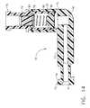
- the assembly of the valve 70is best shown in Figure 14.
- the filter 77is attached to the inside of the cylinder 80 in a groove 84.
- the filter 77is permeable by air and fluids and provides a support for the spring 78 which biases the piston 79 against a valve seat 83 of the cylinder 80, thus preventing the escape of fluids out the proximal end 74 of the valve 70.
- the connector 97(see Figure 1) for attaching the third tube 95 to the valve 70 is adapted to releaseably attach to the proximal end 74 of the valve 70 in a manner well-known in the art as a Luer connection, so that when so connected, the piston 79 is held away from the valve seat 83, thus allowing the flow of fluids through the valve 70. When disconnected, the piston is again allowed to seal against the valve seat due to the biasing force of the spring 78 and the fluidic pressure within the valve 70. Syringes are commercially available for sealably attaching to the proximal end 74 of the valve 70.
- the tip of the syringe pressing on the piston 79 and/or the injection pressure of the solution coming out of the syringeis sufficient to overcome the spring 78 and to push the piston 79 away from the valve seat 83, so that the solution may flow through the valve.
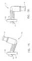
- FIGs 15 and 16it is shown how a groove 76 on the valve 70 is used advantageously to position the valve 70 into cradle 104 of the driver 100 of Figure 1.
- the valve 70is attached to the probe 12 and to the third tube 95 on proximal end 74 of the valve when it is so positioned, but those items have been omitted from Figures 15 and 16 for clarity.
- the valve 70is initially lowered into the cradle 104 with the proximal end 74 of the valve oriented in the up direction.
- the groove 76 of the valve 70is beveled to allow the valve to be tipped as shown, in turn allowing the distal end of the probe 12 to be lowered into the driver after the valve has been properly seated in the cradle.
- This tipping method of inserting the probe 12 into the driver 100removes the necessity of having to locate the probe 12 into the mounting fork 102, the cutter advance fork 112, and the cradle 104 simultaneously.
- the valve 70is rotated to the downward position as shown in Figure 16. This results in the vacuum line 95 hanging naturally from the probe 12 in the downward direction.
- Axial play of the valve 70is minimal due to the configuration of the groove 76 for mounting in the cradle 104. Minimizing the axial play of the valve 70 and the attached tissue remover 60 is important in maintaining the positional relationship of the distal tip 61 of the remover 60 to the cutting blade 51 in order to knock-out properly the tissue sample from the cutter 50 as earlier described.
- Figure 7shows the hub 2 of the distal frame seal 1 in an enlarged, isometric view.
- the hub 2is inserted into frame 40 of the piercer 20, and rotatably supports the proximal end 24 of the piercing element 25.
- the hub 2 of Figure 7comprises a first and a second O-ring seat, 4 and 5, respectively, a plurality of glands 3 for the sealable insertion into the frame 40 of the piercer 10.
- the hub 2further comprises a hub step 19 extending distally from a proximal surface 9, wherein the hub step 19 is a supporting means for the positioning wheel 30 (see Figure 3).
- a crush rib 8 on the hub step 19aids in retaining the positioning wheel 30 to the hub 2.
- a locating projection 7 on the hub step 19properly aligns the hub 2 with the positioning wheel 30 radially, so that the port 26 on the distal end 22 of the piercer 10 is in the up position when the marker 31 of the positioning wheel 30 is also in the up position.
- the distal frame seal 1is shown assembled into the distal end 48 of the frame 40.
- the distal frame seal 1comprises the hub 2 and a first O-ring 120 and a second O-ring 121.
- a first radial space 122which is occupied by part of the distal frame seal 1, is defined by the radial clearance between the piercing element 20 (partially shown) and the proximal end 48 of the frame 40.
- a lower lumen vacuum boss 41is in alignment between the two O-rings 120 and 121 so as to allow vacuum to be delivered through passages 35 and into opening 6 of the distal frame seal 1.
- the first tube 91(see Figure 1) from the first reservoir 90 is a flexible, medical grade tube which may fit tightly over the vacuum boss 41.
- the proximal end 24 of the lower lumen 23 of the piercing element 25is inserted into the opening 6 of the distal frame seal 1 so that the vacuum may be delivered through the lower lumen 23 and to the port 26 on the distal end 22 of the piercer 20.
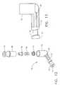
- connection of the first tube 91 to the vacuum boss 41may be facilitated by any one of a number of embodiments of connectors.
- Such connectorsmay be made, for example, of a semi-rigid, medical grade elastomer such as polyurethane exhibiting improved frictional characteristics at the attachment interfaces to the vacuum boss 41 and the tube 91, as compared to when the tube is attached directly to the boss.
- the use of such a connectorwould provide an advantage to the surgeon of helping to prevent the accidental disconnection of the tube 91 from the vacuum boss 41 during the use of the present invention.
- Such a connectorcould be configured in a "L" shape or elbow so that the angle of attachment of the tube 91 with respect to the probe axis could vary by swiveling the connector upon the vacuum boss 41. This would be useful to the surgeon when positioning the probe in various orientations during the surgical procedure.
- FIG 8shows the proximal frame seal 11 in an enlarged, isometric view.
- the proximal frame seal 11is also shown in Figure 9 as it is assembled into the proximal end 49 of the frame 40.
- the proximal frame seal 11comprises an opening 13, a gland 14, a round portion 15 projecting distally from a proximal surface 18 of a rectangular portion 16.
- a retention tab 17projects from the top of the rectangular portion 16 for the elastic insertion into a hole 36 of the frame 40.
- the proximal frame sealoccupies a second radial space 124 defined by the clearance between the cutter tube 53 and the proximal end 49 of the frame 40.
- the proximal frame seal 11substantially prevents the flow of fluids through the second radial space.
- Both of the frame seals, 1 and 11, the O-rings, 120 and 121, and the proximal cutter seal 114may be made any of a number of medical grade polymers and elastomers which can withstand gamma radiation and ethylene oxide (ETO) sterilization techniques for disposable medical products. Examples of such materials available are polyethylene, polypropylene, silicone, and polyurethane.
Landscapes
- Health & Medical Sciences (AREA)
- Life Sciences & Earth Sciences (AREA)
- Medical Informatics (AREA)
- Engineering & Computer Science (AREA)
- Biomedical Technology (AREA)
- Heart & Thoracic Surgery (AREA)
- Pathology (AREA)
- Molecular Biology (AREA)
- Surgery (AREA)
- Animal Behavior & Ethology (AREA)
- General Health & Medical Sciences (AREA)
- Public Health (AREA)
- Veterinary Medicine (AREA)
- Surgical Instruments (AREA)
- Sampling And Sample Adjustment (AREA)
Description
- The present invention relates, in general, to devices for tissue sampling and,more particularly, to improved biopsy probes for acquiring subcutaneous biopsiesand for removing lesions.
- The diagnosis and treatment of patients with cancerous tumors, premalignantconditions, and other disorders has long been an area of intenseinvestigation. Non-invasive methods for examining tissue are palpation, X-ray,MRI, CT, and ultrasound imaging. When the physician suspects that a tissue maycontain cancerous cells, a biopsy may be done either in an open procedure or in apercutaneous procedure. For an open procedure, a scalpel is used by the surgeon tocreate a large incision in the tissue in order to provide direct viewing and access tothe tissue mass of interest. Removal of the entire mass (excisional biopsy) or a partof the mass (incisional biopsy) is done. For a percutaneous biopsy, a needle-likeinstrument is used through a very small incision to access the tissue mass of interest and to obtain a tissue sample for later examination and analysis. The advantages ofthe percutaneous method as compared to the open method are significant: lessrecovery time for the patient, less pain, less surgical time, lower cost, less risk ofinjury to adjacent bodily tissues such as nerves, and less disfigurement of thepatient's anatomy. Use of the percutaneous method in combination with artificialimaging devices such as X-ray and ultrasound has resulted in highly reliablediagnoses and treatments.
- Generally there are two ways to obtain percutaneously a portion of tissuefrom within the body, by aspiration or by core sampling. Aspiration of the tissuethrough a fine needle requires the tissue to be fragmented into small enough piecesto be withdrawn in a fluid medium. The method is less intrusive than other knownsampling techniques, but one can only examine cells in the liquid (cytology) and notthe cells and the structure (pathology). In core biopsy, a core or fragment of tissue isobtained for histologic examination which may be done via a frozen or paraffinsection.
- The type of biopsy used depends mainly on various factors present in thepatient, and no single procedure is ideal for all cases. Core biopsy, however, is veryuseful in a number of conditions and is widely used by physicians.
- Due largely to heightened public awareness of the need to detect breastcancer early in its development, a number of biopsy devices for use in combinationwith artificial imaging devices have been commercialized. One such instrumenttype of biopsy instrument is the BIOPTY gun, available from C.R. Bard, Inc. anddescribed in U.S. Patents No. 4,699,154 and 4,944,308 as well as in U.S. ReissuedPatent No. Re. 34,056. This device is spring-powered and each time a sample is tobe taken, the breast or organ must be punctured again upon re-insertion of the device. Another product is the TRUE CUT needle manufactured by TravenolLaboratories. This needle collects a single core of tissue using a pointed stillete witha side-facing notch to receive tissue near its distal end and an outer, sharpenedsliding cannula.
- Other devices for obtaining biopsy samples from the body are described inthe following: U.S. Patent 5,492,130 issued to Chiou on February 20, 1996; U.S.Patent 5,526,821 issued to Jamshidi on June 18, 1996; U.S. Patent 5,429,138 issue toJamshidi on July 4, 1995; and U.S. Patent 5,027,827 issued to Cody, et al, on July 2,1991. These patents describe devices which may be used for soft tissue biopsiesusing the aspiration method of liquid suspended tissue extraction rather than by coresampling. Numerous other devices are described in the references cited in thisdisclosure, and generally are for the mere removal of tissue rather than the samplingof tissue for later pathological examination.
- To overcome operator error associated with such devices, and to enablemultiple sampling of the tissue without having to reenter the tissue for each sample,a product now marketed under the tradename MAMMOTOME was developed. Theinvention which is the basis of the commercialized product is described in U.S.Patent No. 5,526,822 issued to Burbank, et al, on June 18, 1996, and is commonlyowned by the assignee of the present invention. The MAMMOTOME instrument isa type of image-guided, percutaneous, coring, breast biopsy instrument. It isvacuum-assisted and some of the steps for retrieving the tissue samples have beenautomated. The physician uses this device to capture "actively" (using the vacuum)the tissue prior to severing it from the body. This allows for sampling tissues ofvarying hardness. The device can also be used to collect multiple samples innumerous positions about its longitudinal axis, and without needing to remove the device from the body. These features allow for substantial sampling of large lesionsand complete removal of small ones.
- US Patent No. 5649547, which corresponds to the preamble of
claims 1 and 7, describes numerous improvements to theoriginal invention including the following: a molded tissue cassette housingpermitting the handling and viewing of multiple tissue samples without physicalcontact by the instrument operator; the interconnection of the housing to the piercingneedle using a thumbwheel to permit the needle to rotate relative to the housing,thereby preventing the vacuum tube from wrapping about the housing; severalvariant vacuum port embodiments; and a method for backflushing biological debrisfrom the instrument without removing the instrument from the selected tissuelocation. - When using any of the devices described thus far there is a need to manage asubstantial amount of different fluids either already present at the surgical site orintroduced during the surgical procedure. There is some associated bleeding fromthe surgical site during insertion of the needle and severing of the tissue samplesfrom the tissue mass of interest. In addition, several milliliters of local anestheticsuch as lidocaine hydrochloride solution are injected into the tissue during theprocedure, and there is a significant build-up of pressure inside the tissue due to thepresence of the additional fluid. When the blood and anesthetic solution under thispressure within the tissue are opened to a lower or ambient pressure, the fluids willreadily escape the tissue at the opening. Keeping these fluids from contaminatingthe patient and the instrumentation is obviously an important part of the mandatoryaseptic technique, and features on the biopsy device to help accomplish this areclearly advantageous.
- Coring breast biopsy devices typically incorporate an elongated piercingelement to access the sampling area of the tissue mass, and a cutting cannula with asharpened end which slides longitudinally along the piercing element. Thesharpened end of the cutting cannula is driven into the tissue mass, and a coresample of the tissue is captured into the distal end of the cannula. The piercingelement and/or the cannula are then withdrawn from the body and, in the case of theMAMMOTOME breast biopsy instrument, the tissue sample is transported andremoved from the distal end of the cannula. This is an opportunity for fluids toescape from the tissue mass. The situation is especially acute should the biopsydevice be tilted during the step of sample retrieval, as often occurs when the biopsydevice is mounted on certain imaging devices. The fluids then will tend to flow"downhill" onto the devices and the surroundings.
- Accordingly, what is needed is a biopsy device which can catch the fluidspresent during a biopsy procedure before they spill on the surroundings, and drainthe fluids away to a collection cannister or the like. In addition to dealing with thebackflow and gravitational effects already described, the physician also mustcontend with the fluids being spread by the pumping action of the relatively slidingcomponents of the biopsy device. What is also needed, therefore, are sealsadvantageously mounted between the sliding components to block the spread of thefluids and to wipe the interacting surfaces clean as the device is actuated.
- In the MAMMOTOME device a knockout tube is provided so that as thecutting cannula is withdrawn from the tissue and the distal end of the tube is outsidethe patient's body, the distal end of the knockout tube pushes out the core sampleautomatically from the distal end of the cutting cannula. A drain line is attached tothe proximal end of the knockout tube so that fluids contained in the cutting cannulacan be removed. This drain line may be attached to a vacuum source to remove the fluids more effectively. Sometimes the surgeon wishes to disconnect the drain linefrom the knockout tube in order to inject an additional amount of anesthetic solutioninto the tissue mass to insure that a sufficient amount is present at the area where thetissue sample will be taken. By removing this drain line, the fluid within the tissuewhich may be at a relatively high pressure can escape from the device. What isfurther needed, therefore, is a connecting valve on the device to allow thedisconnection of the drain line, the injection of the anesthetic solution, and thereattachment of the drain line, without the loss of fluids from the tissue and onto theexternal surroundings. This connecting valve would also be an improvement tobiopsy devices which do not have a knockout tube, but which instead have a drainline attached to the proximal end of the cutting cannula or to the proximal end of thepiercing element.
- The present invention is a biopsy device as defined in claim 1 or
claim 7, sometimes referred to simply as aprobe, for obtaining core samples of soft tissue while providing means to capture orcontain the blood, anesthetic solution, and other fluids from within the device andthe tissue mass during the surgical procedure. The proper management of fluidsduring the surgical biopsy procedure, as achieveable with the present invention,greatly minimizes the discomfort to the surgeon and the surgical patient,substantially prevents damage to nearby ancillary equipment, and facilitates asceptictechnique during the procedure. - The probe has a frame with a distal end and a proximal end.A tissue sampling surface is disposed between thedistal and proximal ends of the frame. In a preferred embodiment, a drain line is attachedto the frame for fluid communication with the tissue sampling surface. The tissuesampling surface is in a convenient location for retrieving the tissue sample extracted from the surgical patient. The sampling surface, together with the drain,provide an important improvement over the prior art for the collection and removalof fluids which escape from the body through the probe while retrieving the sample.
- The probe also includes an elongated piercing element having a lumen, asharpened end for piercing the tissue, and a port located proximal to the sharpeneddistal end for receiving a portion of a tissue mass positioned adjacent to the lateralport. The piercing element has a proximal end attached to the distal end of theframe. The probe further comprises an elongated cutter having a lumen and beingdisposed coaxially and slidably relative to the piercing element. The cutter has acutting blade on the distal end for cutting the portion of tissue protruding into theport of the piercing element when the cutting blade slides distally past the lateralopening. The portion of cut tissue is deposited within the lumen of the cutterproximal to the cutting blade.
- In an especially preferred embodiment, the probe includes a tubular tissueremover slideably inserted within the lumen of the cutter and having a structuredisposed proximally of the port and adapted to obstruct the lumen so that a tissuesample within the cutter lumen is prevented from moving proximally. In thispreferred embodiment, a valve is provided on the proximal end of the tissue removertube and is releaseably attachable to a reservoir. The flow of air or fluids throughthe valve is prevented when the reservoir is not attached to it. Conversely, the flowis permitted when it is attached. The valve is also an important improvement overthe prior art because of the new capability to temporarily disconnect the drain tubefrom the probe, inject a solution such as lidocaine hydrochloride anesthetic into thetissue through the valve, and to reconnect the drain tube to the valve, all withminimal backflow of fluids out of the probe through the valve.
- In another embodiment of the present invention, there is provided a proximalframe seal to substantially prevent the passage of fluids through a first radial spacebetween the piercing element and the distal end of the frame of the probe. Further,in a particularly preferred embodiment, a distal frame seal and a proximal cutter sealsubstantially prevent the passage of fluids through second and third radial spaces,respectively. The seals further facilitate fluid management during the surgicalprocedure by substantially preventing the leakage of the fluids from the inside of theprobe.
- The biopsy probe is also provided with a positioning wheel mounted on thedistal end of the frame. The positioning wheel is for rotating the piercing elementabout its longitudinal axis, thus allowing the surgeon to extract tissue samples fromaround the distal end of the probe without rotating the probe frame which may beattached to drain and/or vacuum lines.
- The biopsy probe of this invention can be used in any surgical procedurewhere it is necessary or desirable to take a biopsy tissue sample or to remove asuspected lesion. It is especially adapted for use during a minimally invasiveprocedure, particularly a percutaneous breast biopsy procedure.
- The novel features of the invention are set forth with particularity in theappended claims. The invention itself, however, both as to organization andmethods of operation, together with further objects and advantages thereof, may bestbe understood by reference to the following description, taken in conjunction withthe accompanying drawings in which:
- Figure 1 is an isometric view of a biopsy apparatus, showing the biopsyprobe of Figure 2, its insertion into a driver, and schematic representations of acontrol unit, a plurality of vacuum sources, and a drain;
- Figure 2 is an isometric view of a preferred biopsy probe of the presentinvention;
- Figure 3 is an exploded isometric view of the biopsy probe of Figure 2;
- Figure 4 is an isometric view of a probe frame of the biopsy probe of Figure2;
- Figure 5 is a top view of the probe frame of the biopsy probe of Figure 2;
- Figure 6 is a side view of the probe frame of the biopsy probe of Figure 2;
- Figure 7 is an isometric view of a distal frame seal which inserts into thedistal end of the probe frame of Figure 4;
- Figure 8 is an isometric view of a proximal frame seal which inserts into theproximal end of the probe frame of Figure 4;
- Figure 9 is a longitudinal sectional view of the probe frame of Figure 4assembled with the proximal frame seal of Figure 8 and the distal frame seal ofFigure 7;
- Figure 10 is an isometric view of a proximal cutter seal which mounts on theproximal end of a cutter of the biopsy probe of Figure 2;
- Figure 11 is a longitudinal sectional view of the proximal portion of thecutter of the biopsy probe of Figure 2, assembled with the proximal cutter seal ofFigure 10;
- Figure 12 is an exploded isometric view of a valve which mounts on theproximal end of a tissue remover of the biopsy probe of Figure 2;
- Figure 13 is a side view of a housing of the valve of Figure 12;
- Figure 14 is a sectional view of the valve of Figure 12;
- Figure 15 is a side view of the valve of Figure 12 as it is initially insertedinto a cradle of the driver of Figure 1, with the tissue removal tube and the draintube removed from the valve for clarity; and
- Figure 16 is a side view of the valve of Figure 12 as it is finally inserted intoa cradle of the driver of Figure 2, with the tissue removal tube and the drain tuberemoved from the valve for clarity.
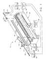
- As best shown in Figure 1, the present invention is a
surgical biopsyapparatus 12, a minimally invasive type of instrument for acquiring repeatedsubcutaneous biopsies. In an especially preferred embodiment, thesurgical biopsyapparatus 12 generally comprises aprobe 10 for insertion into the tissue of thesurgical patient for extraction of a tissue sample therefrom, apowered probe driver 100, a moveable table 98, acontrol unit 96, and a first, a second, and a third tube influid communication with a first, a second, and a third reservoir, respectively. In thepreferred embodiment, thereservoirs probe 10 of thesurgical biopsy apparatus 12 is removeably mounted to the poweredprobe driver 100. - The
driver 100 includes ahousing 109 having amoveable cover 108hingedly attached thereto. Within thehousing 109 there is ahousing mount fork 102 for receiving theprobe 10, acutter advance fork 112 for positioning thecuttergear 59, anelongated driver gear 106 to mate with and rotate thecutter 50. Thedriver 100 is attached to a moveable table 98 such as a stereotactic guidance system(not shown) for moving theprobe 10 distally in order to pierce the tissue, andproximally in order to remove theprobe 10 from the tissue. Acutter advance knob 113 is manually actuated to obtain the tissue sample as will be described. - The
control unit 96 is used to control the sequence of actions performed bythesurgical biopsy apparatus 12 in order to obtain the biopsy sample from thesurgical patient. In the preferred embodiment, thecontrol unit 96 controls theapplication of vacuum to theprobe 10 and the activation of the cutter motor (notshown) within thedriver 100. The range of vacuum pressure preferred is about 58.4-63.5cm (23-25inches) of mercury below atmospheric pressure. - Figure 2 is an isometric view of the preferred embodiment of the
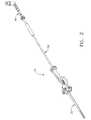
probe 10which is a coaxial assembly of three elongated elements: apiercer 20, acutter 50,and atissue remover 60. Thetissue remover 60 is inserted slideably into thecutter 50 which, in turn, is inserted slideably into the piercingelement 20. Theprobe 10generally is used as follows: The skin of the surgical patient is disinfected. A local anesthetic such as lidocaine hydrochloride is injected by hypodermic needle into thetissue. A small incision is made in the skin of the surgical patient. Then thepiercer 20 is placed into that incision and pierced into the tissue of the surgical patient and isadvanced to the tissue area of interest by the movement of the moveable table 98.During this step thecutter 50 is completely advanced in the distal direction. Oncethe tissue of interest is accessed by thepiercer 20, thecutter 50 is retracted in theproximal direction partway and the tissue to be extracted is drawn by vacuum into adistal end 22 of theprobe 10. Thecutter 50 is then actuated by the cutter motor ofthedriver 100 and manually advanced in the distal direction, thus severing the tissuesample captured in thedistal end 22 of theprobe 10. Thecutter 50 is then manuallyretracted in the proximal direction, transporting the tissue sample to outside thepatient's body. Thetissue remover 60 releases or "knocks-out" the tissue samplefrom thecutter 50, so that the tissue sample may be retrieved for analysis. - Figure 3 is an exploded isometric view of the
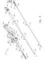
probe 10, showing separatelythepiercer 20, thecutter 50, and thetissue remover 60. Thepiercer 20 comprises aframe 40 which may be made from a rigid, medical grade plastic. Theframe 40 hasadistal end 48, aproximal end 49, and a longitudinal axis (not shown) extendingtherebetween. A tubular piercingelement 25 having aproximal end 24 and adistalend 22 is rotatably attached to theproximal end 48 of theframe 40 by a hub 2(partially shown) and apositioning wheel 30. Rotation of thepositioning wheel 30by the surgeon allows positioning of arectangular port 26 in thedistal end 22 of thepiercer 20. Apositional indicator 31 on thewheel 30 may be referenced to amarker 39 on theframe 40 of theprobe 10. By changing the position of theport 26, thesurgeon may access tissue from anywhere around thedistal end 22 of thepiercer 20. - Piercing
element 25 is preferably made from a stainless steel and includes anupper lumen 21 and alower lumen 23. Therectangular port 26 on thedistal end 22 of the piercingelement 25 is located on theupper lumen 21 and is provided forreceiving the tissue that is to be extracted from the surgical patient. Referring nowto Figures 1 and 3 concurrently, thelower lumen 23 has a plurality of small holes(not shown) in thedistal end 22 for the communication of theport 26 to thefirstreservoir 90. In the preferred embodiment, this first reservoir is a vacuum source sothat the prolapse of tissue into theport 26 is greatly enhanced. Thecutter 50reciprocates axially within theupper lumen 21 as the surgeon manually operates theadvancingknob 113. The piercingtip 28 is attached to thedistal end 22 of thepiercingelement 25 and pierces into the tissue of the surgical patient by the drivingforce of thedriver 100. - Referring to Figures 3 and 4, the
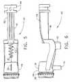
frame 40 of thepiercer 20 has atissuesampling surface 47 which is where a tissue sample extracted from within thesurgical patient is removed from theprobe 10. Samplingsurface 47 is provided withagrate 43 which connects with adrain boss 42 of theframe 40. Figures 4, 5, and 6more clearly show thegrate 43 anddrain boss 42. Thegrate 43 may have manydifferent configurations as will be apparent to those skilled in the art, but in general,thegrate 43 allows the passage of fluids into the drain 92 (see Figure 1) via thesecond tube 93 but prevents the tissue sample from falling into thedrain boss 42.Thedrain boss 42 optionally may be connected to a vacuum source in order toenhance the collection of fluids from the tissue sampling area. - In Figures 4, 5, and 6 can also be seen a plurality of
teeth 38 around theperiphery of thedistal end 48 of theframe 40. Theteeth 38 are for interaction withtheflutes 32 of the positioning wheel 30 (see Figure 1) so that a tactile feedback isprovided to the user while adjusting the location of theport 26 on thedistal end 22of thepiercer 20. In addition to the tactile feedback, theteeth 38 are a holdingmeans for the orientation of theport 26, and also a referencing means. That is, the surgeon may count the number of "detents" felt when rotating thepositioning wheel 30, while looking at the relationship between thepositional indicator 31 on thewheel 30 and themarker 39 on theframe 40, in order to understand the radialorientation of theport 26 on thedistal end 22 of thepiercer 20. - Figure 4 shows a pair of mounting
fins 44 on theproximal end 49 of theframe 40. These mountingfins 44 are removeably inserted into a mountingfork 102of thedriver 100 as depicted in Figure 1, thus anchoring theprobe 10 to thedriver 100, and engaging theprobe 10 to a spring-actuated firing mechanism (not visible)within the driver for instantaneously advancing thedistal end 22 of theprobe 10 intothe tissue of the patient. This firing mechanism may be used, if desired by thesurgeon, in combination with the stereotactic movement of the moveable table 98 toposition thedistal end 22 into the tissue of the patient. - Now referring again to Figures 1 and 3 concurrently, the
cutter 50 comprisesadistal end 52, aproximal end 58, and a longitudinal axis (not shown) extendingtherebetween. Thecutter 50 further comprises acutter shank 56 having adistal end 57 fixedly attached to aproximal end 54 of ahollow cutter tube 53. A longitudinalpassage through the cutter shank 56 (not visible) communicates with thecutter tube 53. On the distal end ofcutter tube 53 is acutter blade 51 which is preferably madeby the sharpening of the circumference of thedistal end 52 of thecutter tube 53,which is preferably made of a stainless steel. On theproximal end 58 of thecutter 50 is acutter gear 59, which is preferably integrally molded with thecutter shank 56. Thecutter gear 59 is for operational engagement with anelongated gear 106 ofthedriver 100. When theprobe 10 is inserted into thedriver 100, thecutter gear 59is positioned into thecutter advance fork 112 of the driver. Thecutter advance fork 112 is attached to thecutter advance knob 113 so that movement of theknob 113causes the like movement of thecutter 50. As thecutter 50 is moved axially by operation of thecutter advance knob 113, thecutter gear 59 moves along theelongated gear 106 of thedriver 100, while maintaining operational engagement.The electric motor (not shown) of the driver rotates thecutter 50 at a preferred rateof about 1350 revolutions per minute, although the rate may vary considerably. - A
proximal cutter seal 114 is attached to the proximal end of thecutter 50.Thetissue remover 60 slides freely through theproximal cutter seal 114. The radialclearance or gap between thecutter 50 and thetissue remover 60 defines a thirdradial space 126 (see Figure 11). The distal end of thecutter 50 is inside the tissueof the patient during certain portions of the operational sequence, and fluids such asblood and injected lidocaine may be under considerable pressure within the tissue.Also, theprobe 12 may be tilted at an angle with respect to the earth, and fluids willtend to flow downhill (in the proximal direction) and drip/spill onto nearbyinstrumentation, the surgical table, and so forth. Theproximal cutter seal 114substantially prevents these fluids from escaping from theproximal end 58 of thecutter 50 through the thirdradial clearance 126. Figure 10 shows an enlarged,isometric view of theproximal cutter seal 114. Figure 11 shows theproximal cutterseal 114 retained on theproximal end 58 of thecutter shank 56. Acutter seal lip 116 elastically snaps over anannular rib 55 of theproximal end 58 of thecuttershank 56. Aresilient opening 118 slideably receives and seals against aremovertube 63 of thetissue remover 60, thus substantially preventing the escape of fluidsfrom within thecutter shank 56 through the thirdradial clearance 126. - The
cutter tube 53 fits closely yet slides freely in aframe hole 45 whichextends longitudinally throughframe bushing 46 of thepiercer 20. When thecutter 50 is retracted to a first position as described earlier, thecutter blade 51 of thecutter 50 is approximately adjacent to framesurface 82 of thepiercer 20 so as to allow freeaccess to thesampling surface 47 for retrieval of the tissue sample. In Figure 1, thecutter blade 51 is shown extending about ten millimeters distal to where it would befor the first, retracted position of thecutter 50. - In Figure 3, the
tissue remover 60 comprises aremover tube 63 which has aproximal end 64, adistal end 62, and a longitudinal axis (not shown) extendingtherebetween. On theproximal end 64 of theremover tube 63 is attached avalve 70having adistal end 72 , aproximal end 74 which is perpendicular to thedistal end 72, and a passageway therethrough. The remover tube is hollow and preferably ismade from a stainless steel. A distal tip 61 (also referred to simply as a structure) onthedistal end 62 of theremover tube 63 is configured so as to allow the passage ofair and fluids and to block the passage of tissue particles larger than what may passthrough thetissue remover 60 and thevalve 70. Thedistal tip 61 prevents the lossof tissue into the reservoir which may otherwise be collected for pathologicalanalysis. The length of theremover tube 63 is such that when thecutter 50 isretracted to the first position, thedistal tip 61 of theremover tube 63 isapproximately adjacent to thecutter blade 51 of thecutter 50. This arrangementallows the tissue sample retrieved in thedistal end 52 of thecutter 50 to be forcedout of the same by thedistal tip 61 of thetissue remover 60 when thecutter 50 isretracted to the first position. The tissue sample may then drop onto thetissuesample surface 47 of thepiercer 10. - The
valve 70 of thetissue remover 60 is shown in Figure 12 (explodedisometric view), Figure 13 (side view of thehousing 81 only) and Figure 14(sectional view). Thevalve 70 provides for the flow of air and fluids from thetissueremover 60 to thethird reservoir 95 via thethird tube 95 and a connector 97 (seeFigure 1). In the preferred embodiment, thethird reservoir 95 is a vacuum sourcewhich facilitates the removal of the fluids from within theprobe 10, and whichfacilitates the transport of the tissue sample from theport 26 to the tissue sampling surface 47 (see Figure 1). Because thetissue remover 60 is inserted into thecutter 50 which is inserted in-theupper lumen 21 of thepiercer 20, the vacuum source isconnected to theupper lumen 21 as well and assists in drawing tissue into theport 26 prior to cutting of the tissue by thecutter blade 51. In addition to the removal offluids from theprobe 20, the vacuum provides a means of releaseably attaching thetissue sample to the end of thetissue remover 60 so that once severed, the samplemay be held in thedistal end 52 of thecutter tube 53 and transported from theport 26 of thepiercer 20 to outside the patient's body to thetissue sampling surface 47 oftheprobe 10. - The
valve 70 also provides a closeable port for injecting fluids into the tissueof the surgical patient. For example, as the piercingtip 28 of theprobe 10 is piercedinto tissue in order to access the tissue area of interest, it is common for surgeons toinject a lidocaine hydrochloride local anesthetic into the tissue through theport 26on theupper lumen 21 of thepiercer 20 via the proximal end oftissue remover tube 63 which is in fluid communication with theupper lumen 21. Thevalve 70 allowsthe surgeon to disconnect thethird tube 95 from theproximal end 74 of the valve, touse a syringe to inject the lidocaine through theproximal end 74 and into the tissue,and then to remove the syringe without the lidocaine and other fluids escaping fromtheprobe 10. Therefore, in this situation, the syringe is considered anotherembodiment of thethird reservoir 94. The novel combination of thevalve 70 withtheprobe 10 prevents the escape of fluids from the proximal end of the probe whenneither thethird tube 95 or the syringe are connected to it. - The
valve 70 comprises ahousing 81, afilter 77 containing smallpassageways therethrough (not visible), acoiled spring 78, apiston 79, and acylinder 80. Thehousing 81, which is preferably made of a rigid, medical gradeplastic, has ahollow stem 73 protruding perpendicularly from abowl 75, with a communicating passageway therebetween. Thedistal end 72 of thevalve 70 isfixedly attached to thetissue remover tube 63 as shown in Figure 3. Thebowl 75receives thecylinder 80 which contains thespring 78, thepiston 79, and thefilter 77. Thecylinder 80 is sealably bonded within thepipe 75 of thehousing 81 by anyof a number of bonding techniques well-known to those skilled in the manufactureof medical valves and the like. The assembly of thevalve 70 is best shown in Figure14. Thefilter 77 is attached to the inside of thecylinder 80 in agroove 84. Thefilter 77 is permeable by air and fluids and provides a support for thespring 78which biases thepiston 79 against avalve seat 83 of thecylinder 80, thus preventingthe escape of fluids out theproximal end 74 of thevalve 70. The connector 97 (seeFigure 1) for attaching thethird tube 95 to thevalve 70 is adapted to releaseablyattach to theproximal end 74 of thevalve 70 in a manner well-known in the art as aLuer connection, so that when so connected, thepiston 79 is held away from thevalve seat 83, thus allowing the flow of fluids through thevalve 70. Whendisconnected, the piston is again allowed to seal against the valve seat due to thebiasing force of thespring 78 and the fluidic pressure within thevalve 70. Syringesare commercially available for sealably attaching to theproximal end 74 of thevalve 70. The tip of the syringe pressing on thepiston 79 and/or the injection pressure ofthe solution coming out of the syringe is sufficient to overcome thespring 78 and topush thepiston 79 away from thevalve seat 83, so that the solution may flowthrough the valve. - In Figures 15 and 16, it is shown how a
groove 76 on thevalve 70 is usedadvantageously to position thevalve 70 intocradle 104 of thedriver 100 of Figure 1.Of course, thevalve 70 is attached to theprobe 12 and to thethird tube 95 onproximal end 74 of the valve when it is so positioned, but those items have beenomitted from Figures 15 and 16 for clarity. Now referring to Figure 15 and Figure 1concurrently, thevalve 70 is initially lowered into thecradle 104 with theproximal end 74 of the valve oriented in the up direction. Thegroove 76 of thevalve 70 isbeveled to allow the valve to be tipped as shown, in turn allowing the distal end oftheprobe 12 to be lowered into the driver after the valve has been properly seated inthe cradle. This tipping method of inserting theprobe 12 into thedriver 100removes the necessity of having to locate theprobe 12 into the mountingfork 102,thecutter advance fork 112, and thecradle 104 simultaneously. Once theentireprobe 12 has been lowered into the driver, thevalve 70 is rotated to the downwardposition as shown in Figure 16. This results in thevacuum line 95 hanging naturallyfrom theprobe 12 in the downward direction. Axial play of thevalve 70 is minimaldue to the configuration of thegroove 76 for mounting in thecradle 104.Minimizing the axial play of thevalve 70 and the attachedtissue remover 60 isimportant in maintaining the positional relationship of thedistal tip 61 of theremover 60 to thecutting blade 51 in order to knock-out properly the tissue samplefrom thecutter 50 as earlier described. - Figure 7 shows the
hub 2 of the distal frame seal 1 in an enlarged, isometricview. As was described earlier for Figure 3, thehub 2 is inserted intoframe 40 ofthepiercer 20, and rotatably supports theproximal end 24 of the piercingelement 25. Thehub 2 of Figure 7 comprises a first and a second O-ring seat, 4 and 5,respectively, a plurality of glands 3 for the sealable insertion into theframe 40 of thepiercer 10. Thehub 2 further comprises ahub step 19 extending distally from aproximal surface 9, wherein thehub step 19 is a supporting means for thepositioning wheel 30 (see Figure 3). Acrush rib 8 on thehub step 19 aids inretaining thepositioning wheel 30 to thehub 2. A locatingprojection 7 on thehubstep 19 properly aligns thehub 2 with thepositioning wheel 30 radially, so that theport 26 on thedistal end 22 of thepiercer 10 is in the up position when themarker 31 of thepositioning wheel 30 is also in the up position. - In Figure 9, the distal frame seal 1 is shown assembled into the
distal end 48of theframe 40. The distal frame seal 1 comprises thehub 2 and a first O-ring 120and a second O-ring 121. A firstradial space 122, which is occupied by part of thedistal frame seal 1, is defined by the radial clearance between the piercing element20 (partially shown) and theproximal end 48 of theframe 40. A lowerlumenvacuum boss 41 is in alignment between the two O-rings passages 35 and intoopening 6 of the distal frameseal 1. The first tube 91 (see Figure 1) from thefirst reservoir 90 is a flexible,medical grade tube which may fit tightly over thevacuum boss 41. Theproximalend 24 of thelower lumen 23 of the piercingelement 25 is inserted into theopening 6 of the distal frame seal 1 so that the vacuum may be delivered through thelowerlumen 23 and to theport 26 on thedistal end 22 of thepiercer 20. - Although not shown in Figure 9, it can be appreciated by those skilled in theart that the connection of the
first tube 91 to thevacuum boss 41 may be facilitatedby any one of a number of embodiments of connectors. Such connectors may bemade, for example, of a semi-rigid, medical grade elastomer such as polyurethaneexhibiting improved frictional characteristics at the attachment interfaces to thevacuum boss 41 and thetube 91, as compared to when the tube is attached directlyto the boss. The use of such a connector would provide an advantage to the surgeonof helping to prevent the accidental disconnection of thetube 91 from thevacuumboss 41 during the use of the present invention. Such a connector could beconfigured in a "L" shape or elbow so that the angle of attachment of thetube 91with respect to the probe axis could vary by swiveling the connector upon thevacuum boss 41. This would be useful to the surgeon when positioning the probe invarious orientations during the surgical procedure. - Figure 8 shows the
proximal frame seal 11 in an enlarged, isometric view.Theproximal frame seal 11 is also shown in Figure 9 as it is assembled into theproximal end 49 of theframe 40. Theproximal frame seal 11 comprises anopening 13, agland 14, around portion 15 projecting distally from aproximal surface 18 of arectangular portion 16. Aretention tab 17 projects from the top of therectangularportion 16 for the elastic insertion into ahole 36 of theframe 40. The proximalframe seal occupies a secondradial space 124 defined by the clearance between thecutter tube 53 and theproximal end 49 of theframe 40. Theproximal frame seal 11substantially prevents the flow of fluids through the second radial space. - Both of the frame seals, 1 and 11, the O-rings, 120 and 121, and the proximalcutter seal 114 (see Figure 3) may be made any of a number of medical gradepolymers and elastomers which can withstand gamma radiation and ethylene oxide(ETO) sterilization techniques for disposable medical products. Examples of suchmaterials available are polyethylene, polypropylene, silicone, and polyurethane.
- While preferred embodiments of the present invention have been shown anddescribed herein, it will be obvious to those skilled in the art that such embodimentsare provided by way of example only. Numerous variations, changes, andsubstitutions will now occur to those skilled in the art without departing from theinvention. Accordingly, it is intended that the invention be limited only by thescope of the appended claims.
Claims (9)
- A biopsy probe (10) for the collection of at least one soft tissue sample from asurgical patient, said biopsy probe (10) comprising:the biopsy probe (10) further comprises a tissue sampling surface (47) disposed onthe frame between the proximal and distal ends (48, 49) of said frame (40), in a convenientlocation for the retrieval of the portion of the tissue mass positioned adjacent to said port(26) on the piercing element (25) from the tissue sampling surface (47) upon retracting thecutter (50), the probe being configured such that a tissue sample, if within said cutterlumen, will drop onto the tissue sample surface (47) upon retracting the cutter (50) backfrom the port (26).a) a frame (40) having a distal end (48) and a proximal end (49);b) an elongated piercing element (25) attached to the distal end (48) of saidframe (40), said piercing element (25) having a piercer lumen, a sharpened distal end (22)for piercing tissue, and a port (26) located proximal to said sharpened distal end (22) forreceiving a portion of a tissue mass positioned adjacent to said port (26), said piercingelement (25) and the distal end (48) of said frame (40) defining a first radial space (122)therebetween;c) an elongated cutter (50) having a proximal end, distal end, and a cutterlumen therethrough, said cutter (50) being disposed coaxially and slideably relative to saidpiercing element (25), said cutter (50) having a cutting blade (51) on said distal end forcutting the portion of tissue protruding into said port (26) of said piercing element (25)when said cutter (50) slides distally past said port (26), thereby depositing the portion ofcut tissue within said cutter lumen of said cutter proximal to said cutting blade (51), thecutter (50) and the proximal end (49) of said frame (40) defining a second radial space(124) therebetween; andd) a distal frame seal (1) mounted to seal the first radial space (122) at thedistal end (48) of said frame (40), said distal frame seal (1) adapted to substantiallyobstruct the passage of fluids through the first radial space (122) between said piercingelement (25) and said distal end (48) of said frame (40)characterised in that;
- The biopsy probe (10) of Claim 1 further comprising a proximal frame seal (11)mounted to seal the second radial space (124) at the proximal end (49) of said frame (40), said proximal frame seal (11) adapted to substantially obstruct the passage of fluidsthrough the second radial space (124) between said cutter (50) and said proximal end (49)of said frame (40).
- The biopsy probe (10) of Claim 2 further comprising a tubular tissue remover (60)having a proximal end (64) and a distal end (62), said remover (60) disposed in said cutterlumen of said cutter (50) and having a structure (61) on the distal end (62) thereof anddisposed proximally of said port (26), said structure (61) adapted to obstruct said cutterlumen so that the portion of cut tissue severed by said cutter (50) is prevented from movingproximally through said cutter lumen, the tissue remover (60), and the proximal end of saidcutter defining a third radial space (126) therebetween; and a proximal cutter seal (114)mounted to seal the third radial space (126) at the proximal end of said cutter (50), saidcutter seal (114) adapted to substantially obstruct the passage of fluid through said thirdradial space (126) between the proximal end of said cutter (50) and said tissue remover(60).
- The biopsy probe (10) of claim 3 further comprising a valve (70) having proximaland distal ends, the distal end of said valve (70) is attached to the proximal end (64) of saidtissue remover (60) and the proximal end of said valve (70) is releasably attachable to areservoir for fluid communication from said tissue remover (60) to said reservoir throughsaid valve (70), wherein the passage of air and fluids through said valve (70) occurs onlywhen the proximal end of said valve (70) is attached to said reservoir.
- The biopsy probe (10) of any one of the preceding Claims further comprising a tube(93) attached to said frame (40) and in fluid communication with said tissue samplingsurface (47) of said frame (40), said tube (93) providing for the removal of fluids from saidtissue sampling surface (47).
- The biopsy probe (10) of any one of the preceding Claims, further comprising apositioning wheel (30) rotatably mounted on the distal end (48) of said frame (40) for therotation of said piercing element (25) about its longitudinal axis.
- A biopsy probe (10) for the collection of at least one soft tissue sample from asurgical patient, said biopsy device (10) comprising:a tissue sampling surface (47) disposed on the frame between the proximal anddistal ends (48, 49) of said frame (40) in a convenient position for the retrieval of theportion of the tissue mass positioned adjacent to said port (26) on the piercing element (25)from the tissue sampling surface (47) upon retracting the cutter (50), the probe beingconfigured such that a tissue sample, if within said cutter lumen, will drop onto the tissuesample surface (47) upon retracting the cutter (50) back from the port (26).a) a frame (40) having a distal end (48) and a proximal end (49);b) an elongated piercing element (25) attached to the distal end (48) of saidframe (40), said piercing element (25) having a piercer lumen, a sharpened distal end (28)for piercing tissue, and a port (26) located proximal to said sharpened distal end (28) forreceiving a portion of a tissue mass positioned adjacent to said port (26), said piercingelement (25) and the distal end (48) of said frame (40) defining a first radial space (122)therebetween;c) an elongated cutter (50) having a proximal end (54), a distal end (52), and a cutterlumen therethrough, said cutter (50) being disposed coaxially and slideably relative to saidpiercing element (25), said cutter (50) having a cutting blade (51) on said distal end forcutting the portion of tissue protruding into said port (26) of said piercing element (25)when said cutter slides distally past said port (26), thereby depositing the portion of cuttissue within said cutter lumen of said cutter proximal to said cutting blade (51), said cutter(50) and the proximal end (49) of said frame (40) defining a second radial space (124)therebetween; andd) a tubular tissue remover (60) having a proximal end (64) and a distal end(62), said remover (60) disposed in said cutter lumen of said cutter (50) and having astructure (61) on the distal end thereof and disposed proximally of said port (26), saidstructure (61) for obstructing said cutter lumen so that the portion of cut tissue severed bysaid cutter (50) is prevented from moving proximally through said cutter lumen, the tissueremover (60) and the proximal end of said cutter (50) defining a third radial space (126)therebetween;characterised in that the probe (10) further comprises:e) a proximal cutter seal (114) mounted to seal the third radial space (126) atthe proximal end of said cutter (50), said cutter seal (114) adapted to substantially obstructthe passage of fluid through said third radial space (126) between the proximal end (54) ofsaid cutter (50) and said tissue remover (60);f) a valve (70) having a proximal and a distal end (74, 72), wherein the distal end (72)of said valve (70) is attached to the proximal end (64) of said tissue remover (60) and theproximal end (74) of said valve (70) is releasably attachable to a reservoir for fluidcommunication from said tissue remover (60), to said reservoir through said valve (70), wherein the passage of air and fluids through said valve (70) occurs only when theproximal end (74) of said valve (70) is attached to said reservoir; and
- The biopsy probe (10) of Claim 7, further comprising a distal frame seal (1)mounted to seal the first radial space (122) at the distal end (48) of said frame (40), saiddistal frame seal (1) adapted to substantially obstruct the passage of fluids through the firstradial space (122) between said piercing element (25) and the distal end (48) of said frame(40).
- The biopsy probe (10) of Claim 8, further comprising a proximal frame seal (11)mounted within the second radial space (124) at the proximal end (49) of said frame (40),said proximal frame seal (11) adapted to substantially obstruct the passage of fluidsthrough the second radial space (124) between said cutter (50) and the proximal end (49)of said frame.
Priority Applications (1)
| Application Number | Priority Date | Filing Date | Title |
|---|---|---|---|
| EP05075711AEP1550404B1 (en) | 1998-06-30 | 1999-06-29 | Surgical biopsy device |
Applications Claiming Priority (2)
| Application Number | Priority Date | Filing Date | Title |
|---|---|---|---|
| US09/107,845US6007497A (en) | 1998-06-30 | 1998-06-30 | Surgical biopsy device |
| US107845 | 1998-06-30 |
Related Child Applications (1)
| Application Number | Title | Priority Date | Filing Date |
|---|---|---|---|
| EP05075711ADivisionEP1550404B1 (en) | 1998-06-30 | 1999-06-29 | Surgical biopsy device |
Publications (2)
| Publication Number | Publication Date |
|---|---|
| EP0970658A1 EP0970658A1 (en) | 2000-01-12 |
| EP0970658B1true EP0970658B1 (en) | 2005-08-17 |
Family
ID=22318789
Family Applications (2)
| Application Number | Title | Priority Date | Filing Date |
|---|---|---|---|
| EP99305131AExpired - LifetimeEP0970658B1 (en) | 1998-06-30 | 1999-06-29 | Surgical biopsy device |
| EP05075711AExpired - LifetimeEP1550404B1 (en) | 1998-06-30 | 1999-06-29 | Surgical biopsy device |
Family Applications After (1)
| Application Number | Title | Priority Date | Filing Date |
|---|---|---|---|
| EP05075711AExpired - LifetimeEP1550404B1 (en) | 1998-06-30 | 1999-06-29 | Surgical biopsy device |
Country Status (7)
| Country | Link |
|---|---|
| US (1) | US6007497A (en) |
| EP (2) | EP0970658B1 (en) |
| JP (1) | JP4290283B2 (en) |
| AU (1) | AU745526B2 (en) |
| CA (1) | CA2276385C (en) |
| DE (2) | DE69936894T2 (en) |
| ES (2) | ES2292047T3 (en) |
Cited By (13)
| Publication number | Priority date | Publication date | Assignee | Title |
|---|---|---|---|---|
| US7229439B2 (en) | 1998-03-03 | 2007-06-12 | Senorx, Inc. | Apparatus and method for accessing a body site |
| US7282034B2 (en) | 1998-09-01 | 2007-10-16 | Senorx, Inc. | Tissue accessing and anchoring device and method |
| US7357801B2 (en) | 1998-04-08 | 2008-04-15 | Senorx, Inc. | Tissue specimen isolating and damaging device and method |
| US7377902B2 (en) | 1998-04-08 | 2008-05-27 | Senorx, Inc. | Biopsy anchor device with cutter |
| US7651467B2 (en) | 1998-04-08 | 2010-01-26 | Senorx, Inc | Dilation devices and methods for removing tissue specimens |
| US7670299B2 (en) | 2006-03-07 | 2010-03-02 | Ethincon Endo-Surgery, Inc. | Device for minimally invasive internal tissue removal |
| US7806834B2 (en) | 2006-03-07 | 2010-10-05 | Devicor Medical Products, Inc. | Device for minimally invasive internal tissue removal |
| US7819819B2 (en) | 2003-02-24 | 2010-10-26 | Senorx, Inc. | Biopsy device with inner cutting member |
| US8282573B2 (en) | 2003-02-24 | 2012-10-09 | Senorx, Inc. | Biopsy device with selectable tissue receiving aperture orientation and site illumination |
| US8317725B2 (en) | 2005-08-05 | 2012-11-27 | Senorx, Inc. | Biopsy device with fluid delivery to tissue specimens |
| US8343071B2 (en) | 2004-12-16 | 2013-01-01 | Senorx, Inc. | Biopsy device with aperture orientation and improved tip |
| US8641640B2 (en) | 2005-05-23 | 2014-02-04 | Senorx, Inc. | Tissue cutting member for a biopsy device |
| US9408592B2 (en) | 2003-12-23 | 2016-08-09 | Senorx, Inc. | Biopsy device with aperture orientation and improved tip |
Families Citing this family (218)
| Publication number | Priority date | Publication date | Assignee | Title |
|---|---|---|---|---|
| US6540693B2 (en) | 1998-03-03 | 2003-04-01 | Senorx, Inc. | Methods and apparatus for securing medical instruments to desired locations in a patients body |
| US6331166B1 (en) | 1998-03-03 | 2001-12-18 | Senorx, Inc. | Breast biopsy system and method |
| US6261241B1 (en) | 1998-03-03 | 2001-07-17 | Senorx, Inc. | Electrosurgical biopsy device and method |
| US6391005B1 (en) | 1998-03-30 | 2002-05-21 | Agilent Technologies, Inc. | Apparatus and method for penetration with shaft having a sensor for sensing penetration depth |
| US20010047183A1 (en)* | 2000-04-05 | 2001-11-29 | Salvatore Privitera | Surgical device for the collection of soft tissue |
| US20080146965A1 (en) | 2003-08-11 | 2008-06-19 | Salvatore Privitera | Surgical Device for The Collection of Soft Tissue |
| US6086544A (en)* | 1999-03-31 | 2000-07-11 | Ethicon Endo-Surgery, Inc. | Control apparatus for an automated surgical biopsy device |
| US6248081B1 (en)* | 1999-09-28 | 2001-06-19 | Scimed Life Systems, Inc. | Endoscopic submucosal core biopsy device |
| US6535756B1 (en)* | 2000-04-07 | 2003-03-18 | Surgical Navigation Technologies, Inc. | Trajectory storage apparatus and method for surgical navigation system |
| US6494844B1 (en) | 2000-06-21 | 2002-12-17 | Sanarus Medical, Inc. | Device for biopsy and treatment of breast tumors |
| US6589173B1 (en)* | 2000-07-17 | 2003-07-08 | The Regents Of The University Of California | Ultrasound system for disease detection and patient treatment |
| US6585664B2 (en) | 2000-08-02 | 2003-07-01 | Ethicon Endo-Surgery, Inc. | Calibration method for an automated surgical biopsy device |
| IL154323A0 (en) | 2000-08-21 | 2003-09-17 | Target Technologies Ltd V | Radioactive emission detector equipped with a position tracking system and utilization thereof with medical systems and in medical procedures |
| US6572578B1 (en) | 2000-08-25 | 2003-06-03 | Patrick A. Blanchard | Fluid-jet catheter and its application to flexible endoscopy |
| US6712773B1 (en) | 2000-09-11 | 2004-03-30 | Tyco Healthcare Group Lp | Biopsy system |
| US6610020B2 (en)* | 2000-10-13 | 2003-08-26 | Ethicon Endo-Surgery, Inc. | Fork assembly for a surgical biopsy device |
| US6712774B2 (en) | 2000-10-13 | 2004-03-30 | James W. Voegele | Lockout for a surgical biopsy device |
| US6730044B2 (en) | 2000-10-13 | 2004-05-04 | Ethicon Endo-Surgery, Inc. | Firing mechanism for use in a surgical biopsy device |
| US6602203B2 (en) | 2000-10-13 | 2003-08-05 | Ethicon Endo-Surgery, Inc. | Remote thumbwheel for a surgical biopsy device |
| US6656133B2 (en) | 2000-10-13 | 2003-12-02 | Ethicon Endo-Surgery, Inc. | Transmission assembly for a surgical biopsy device |
| US6540694B1 (en) | 2000-10-16 | 2003-04-01 | Sanarus Medical, Inc. | Device for biopsy tumors |
| AU2002211568B2 (en)* | 2000-10-16 | 2005-11-17 | Sanarus Medical, Inc. | Device for biopsy of tumors |
| US7458940B2 (en) | 2000-11-06 | 2008-12-02 | Suros Surgical Systems, Inc. | Biopsy apparatus |
| WO2002069808A2 (en) | 2000-11-06 | 2002-09-12 | Suros Surgical Systems, Inc. | Biopsy apparatus |
| US6758824B1 (en) | 2000-11-06 | 2004-07-06 | Suros Surgical Systems, Inc. | Biopsy apparatus |
| US8641644B2 (en) | 2000-11-21 | 2014-02-04 | Sanofi-Aventis Deutschland Gmbh | Blood testing apparatus having a rotatable cartridge with multiple lancing elements and testing means |
| EP1339326B1 (en) | 2000-11-27 | 2013-03-06 | Covidien LP | Tissue sampling and removal apparatus |
| US6432064B1 (en) | 2001-04-09 | 2002-08-13 | Ethicon Endo-Surgery, Inc. | Biopsy instrument with tissue marking element |
| US6620111B2 (en)* | 2001-04-20 | 2003-09-16 | Ethicon Endo-Surgery, Inc. | Surgical biopsy device having automatic rotation of the probe for taking multiple samples |
| US7041068B2 (en) | 2001-06-12 | 2006-05-09 | Pelikan Technologies, Inc. | Sampling module device and method |
| US8337419B2 (en) | 2002-04-19 | 2012-12-25 | Sanofi-Aventis Deutschland Gmbh | Tissue penetration device |
| US7344507B2 (en) | 2002-04-19 | 2008-03-18 | Pelikan Technologies, Inc. | Method and apparatus for lancet actuation |
| US9427532B2 (en) | 2001-06-12 | 2016-08-30 | Sanofi-Aventis Deutschland Gmbh | Tissue penetration device |
| JP4209767B2 (en) | 2001-06-12 | 2009-01-14 | ペリカン テクノロジーズ インコーポレイテッド | Self-optimized cutting instrument with adaptive means for temporary changes in skin properties |
| US9226699B2 (en) | 2002-04-19 | 2016-01-05 | Sanofi-Aventis Deutschland Gmbh | Body fluid sampling module with a continuous compression tissue interface surface |
| US7749174B2 (en) | 2001-06-12 | 2010-07-06 | Pelikan Technologies, Inc. | Method and apparatus for lancet launching device intergrated onto a blood-sampling cartridge |
| US9795747B2 (en) | 2010-06-02 | 2017-10-24 | Sanofi-Aventis Deutschland Gmbh | Methods and apparatus for lancet actuation |
| EP1395185B1 (en) | 2001-06-12 | 2010-10-27 | Pelikan Technologies Inc. | Electric lancet actuator |
| JP4272051B2 (en)* | 2001-06-12 | 2009-06-03 | ペリカン テクノロジーズ インコーポレイテッド | Blood sampling apparatus and method |
| US7981056B2 (en) | 2002-04-19 | 2011-07-19 | Pelikan Technologies, Inc. | Methods and apparatus for lancet actuation |
| US6942627B2 (en)* | 2001-07-19 | 2005-09-13 | Ethicon Endo-Surgery, Inc. | Surgical biopsy device having a flexible cutter |
| US7510534B2 (en) | 2001-07-20 | 2009-03-31 | Ethicon Endo-Surgery, Inc. | Method for operating biopsy device |
| US6626849B2 (en)* | 2001-11-01 | 2003-09-30 | Ethicon Endo-Surgery, Inc. | MRI compatible surgical biopsy device |
| EP1524940B1 (en) | 2002-03-19 | 2011-08-24 | Bard Dublin ITC Limited | Biopsy device and biopsy needle module that can be inserted into the biopsy device |
| US8109885B2 (en) | 2002-03-19 | 2012-02-07 | C. R. Bard, Inc. | Biopsy device for removing tissue specimens using a vacuum |
| US7491178B2 (en) | 2002-04-19 | 2009-02-17 | Pelikan Technologies, Inc. | Method and apparatus for penetrating tissue |
| US8267870B2 (en) | 2002-04-19 | 2012-09-18 | Sanofi-Aventis Deutschland Gmbh | Method and apparatus for body fluid sampling with hybrid actuation |
| US7297122B2 (en) | 2002-04-19 | 2007-11-20 | Pelikan Technologies, Inc. | Method and apparatus for penetrating tissue |
| US7901362B2 (en) | 2002-04-19 | 2011-03-08 | Pelikan Technologies, Inc. | Method and apparatus for penetrating tissue |
| US7892183B2 (en) | 2002-04-19 | 2011-02-22 | Pelikan Technologies, Inc. | Method and apparatus for body fluid sampling and analyte sensing |
| US8221334B2 (en) | 2002-04-19 | 2012-07-17 | Sanofi-Aventis Deutschland Gmbh | Method and apparatus for penetrating tissue |
| US8372016B2 (en) | 2002-04-19 | 2013-02-12 | Sanofi-Aventis Deutschland Gmbh | Method and apparatus for body fluid sampling and analyte sensing |
| US7232451B2 (en) | 2002-04-19 | 2007-06-19 | Pelikan Technologies, Inc. | Method and apparatus for penetrating tissue |
| US7547287B2 (en) | 2002-04-19 | 2009-06-16 | Pelikan Technologies, Inc. | Method and apparatus for penetrating tissue |
| US8360992B2 (en) | 2002-04-19 | 2013-01-29 | Sanofi-Aventis Deutschland Gmbh | Method and apparatus for penetrating tissue |
| US8702624B2 (en) | 2006-09-29 | 2014-04-22 | Sanofi-Aventis Deutschland Gmbh | Analyte measurement device with a single shot actuator |
| US7331931B2 (en) | 2002-04-19 | 2008-02-19 | Pelikan Technologies, Inc. | Method and apparatus for penetrating tissue |
| US7909778B2 (en) | 2002-04-19 | 2011-03-22 | Pelikan Technologies, Inc. | Method and apparatus for penetrating tissue |
| US7708701B2 (en) | 2002-04-19 | 2010-05-04 | Pelikan Technologies, Inc. | Method and apparatus for a multi-use body fluid sampling device |
| US9248267B2 (en) | 2002-04-19 | 2016-02-02 | Sanofi-Aventis Deustchland Gmbh | Tissue penetration device |
| US7976476B2 (en) | 2002-04-19 | 2011-07-12 | Pelikan Technologies, Inc. | Device and method for variable speed lancet |
| US8784335B2 (en) | 2002-04-19 | 2014-07-22 | Sanofi-Aventis Deutschland Gmbh | Body fluid sampling device with a capacitive sensor |
| US8579831B2 (en) | 2002-04-19 | 2013-11-12 | Sanofi-Aventis Deutschland Gmbh | Method and apparatus for penetrating tissue |
| US7229458B2 (en) | 2002-04-19 | 2007-06-12 | Pelikan Technologies, Inc. | Method and apparatus for penetrating tissue |
| US7674232B2 (en) | 2002-04-19 | 2010-03-09 | Pelikan Technologies, Inc. | Method and apparatus for penetrating tissue |
| US9314194B2 (en) | 2002-04-19 | 2016-04-19 | Sanofi-Aventis Deutschland Gmbh | Tissue penetration device |
| US9795334B2 (en) | 2002-04-19 | 2017-10-24 | Sanofi-Aventis Deutschland Gmbh | Method and apparatus for penetrating tissue |
| US20030199753A1 (en)* | 2002-04-23 | 2003-10-23 | Ethicon Endo-Surgery | MRI compatible biopsy device with detachable probe |
| US7740597B2 (en)* | 2002-12-11 | 2010-06-22 | Ethicon Endo-Surgery, Inc. | Biopsy device with sample tube |
| US7351210B2 (en)* | 2002-12-11 | 2008-04-01 | Ethicon-Endo-Surgery, Inc. | Biopsy device with piston advance |
| US8574895B2 (en) | 2002-12-30 | 2013-11-05 | Sanofi-Aventis Deutschland Gmbh | Method and apparatus using optical techniques to measure analyte levels |
| US7063672B2 (en)* | 2003-01-31 | 2006-06-20 | Inter-V Manan | Integrated biopsy needle assembly |
| CA2877504C (en)* | 2003-02-25 | 2017-07-25 | Bennie Thompson | Biopsy device with variable speed cutter advance |
| JP4754474B2 (en) | 2003-02-25 | 2011-08-24 | エシコン・エンド−サージェリィ・インコーポレイテッド | Biopsy device with variable speed cutter |
| US7628762B2 (en)* | 2003-03-19 | 2009-12-08 | Suros Surgical Systems, Inc. | Adapter assembly for stereotactic biopsy |
| DE20305093U1 (en) | 2003-03-29 | 2003-09-11 | Heske, Norbert F., 82288 Kottgeisering | Coaxial cannula with sealing element |
| DE10314240B4 (en) | 2003-03-29 | 2025-05-28 | Bard Dublin Itc Ltd. | Pressure generation unit |
| DE602004028463D1 (en) | 2003-05-30 | 2010-09-16 | Pelikan Technologies Inc | METHOD AND DEVICE FOR INJECTING LIQUID |
| EP1889572A3 (en)* | 2003-05-30 | 2008-06-18 | William R. Krause | Biopsy and delivery device |
| US7850621B2 (en) | 2003-06-06 | 2010-12-14 | Pelikan Technologies, Inc. | Method and apparatus for body fluid sampling and analyte sensing |
| WO2006001797A1 (en) | 2004-06-14 | 2006-01-05 | Pelikan Technologies, Inc. | Low pain penetrating |
| US8282576B2 (en) | 2003-09-29 | 2012-10-09 | Sanofi-Aventis Deutschland Gmbh | Method and apparatus for an improved sample capture device |
| US7988642B2 (en) | 2003-10-14 | 2011-08-02 | Suros Surgical Systems, Inc. | Vacuum assisted biopsy device |
| US8048003B2 (en) | 2003-10-14 | 2011-11-01 | Suros Surgical Systems, Inc. | Vacuum assisted biopsy device |
| EP1680014A4 (en) | 2003-10-14 | 2009-01-21 | Pelikan Technologies Inc | METHOD AND DEVICE FOR A VARIABLE USER INTERFACE |
| JP4500315B2 (en) | 2003-10-14 | 2010-07-14 | シュロス・サージカル・システムズ・インコーポレーテッド | Vacuum assisted biopsy needle set |
| US8668656B2 (en) | 2003-12-31 | 2014-03-11 | Sanofi-Aventis Deutschland Gmbh | Method and apparatus for improving fluidic flow and sample capture |
| US7822454B1 (en) | 2005-01-03 | 2010-10-26 | Pelikan Technologies, Inc. | Fluid sampling device with improved analyte detecting member configuration |
| US7402140B2 (en)* | 2004-02-12 | 2008-07-22 | Sanarus Medical, Inc. | Rotational core biopsy device with liquid cryogen adhesion probe |
| US20100198066A1 (en) | 2004-03-12 | 2010-08-05 | Voegele James W | Method and Device for Obtaining Tissue Samples |
| US7465279B2 (en)* | 2004-03-31 | 2008-12-16 | Ethicon Endo-Surgery, Inc. | Marker device and method of deploying a cavity marker using a surgical biopsy device |
| CA2506961C (en)* | 2004-05-11 | 2013-05-07 | Inrad, Inc. | Core biopsy device |
| US8568334B2 (en) | 2004-05-11 | 2013-10-29 | Inrad, Inc. | Core biopsy device |
| WO2006011062A2 (en) | 2004-05-20 | 2006-02-02 | Albatros Technologies Gmbh & Co. Kg | Printable hydrogel for biosensors |
| US7708751B2 (en) | 2004-05-21 | 2010-05-04 | Ethicon Endo-Surgery, Inc. | MRI biopsy device |
| US9638770B2 (en) | 2004-05-21 | 2017-05-02 | Devicor Medical Products, Inc. | MRI biopsy apparatus incorporating an imageable penetrating portion |
| US8932233B2 (en) | 2004-05-21 | 2015-01-13 | Devicor Medical Products, Inc. | MRI biopsy device |
| US9775553B2 (en) | 2004-06-03 | 2017-10-03 | Sanofi-Aventis Deutschland Gmbh | Method and apparatus for a fluid sampling device |
| WO2005120365A1 (en) | 2004-06-03 | 2005-12-22 | Pelikan Technologies, Inc. | Method and apparatus for a fluid sampling device |
| JP4814229B2 (en) | 2004-07-09 | 2011-11-16 | バード ペリフェラル ヴァスキュラー インコーポレイテッド | Transport device for biopsy device |
| US7740596B2 (en) | 2004-09-29 | 2010-06-22 | Ethicon Endo-Surgery, Inc. | Biopsy device with sample storage |
| US20060074345A1 (en) | 2004-09-29 | 2006-04-06 | Hibner John A | Biopsy apparatus and method |
| US20060074344A1 (en) | 2004-09-29 | 2006-04-06 | Hibner John A | Fluid control for biopsy device |
| US8652831B2 (en) | 2004-12-30 | 2014-02-18 | Sanofi-Aventis Deutschland Gmbh | Method and apparatus for analyte measurement test time |
| US7470237B2 (en)* | 2005-01-10 | 2008-12-30 | Ethicon Endo-Surgery, Inc. | Biopsy instrument with improved needle penetration |
| US7517321B2 (en) | 2005-01-31 | 2009-04-14 | C. R. Bard, Inc. | Quick cycle biopsy system |
| US8449477B2 (en)* | 2005-03-02 | 2013-05-28 | Dune Medical Devices Ltd. | Device and method for transporting and handling tissue |
| US20060200041A1 (en) | 2005-03-04 | 2006-09-07 | Ethicon Endo-Surgery, Inc. | Biopsy device incorporating an adjustable probe sleeve |
| US7517322B2 (en) | 2005-03-04 | 2009-04-14 | Ethicon Endo-Surgery, Inc. | Biopsy device with variable side aperture |
| US7556622B2 (en) | 2005-05-18 | 2009-07-07 | Suros Surgical Systems, Inc. | Selectively openable tissue filter |
| US20070060935A1 (en)* | 2005-07-11 | 2007-03-15 | Schwardt Jeffrey D | Apparatus and methods of tissue removal within a spine |
| JP4632887B2 (en)* | 2005-07-15 | 2011-02-16 | オリンパスメディカルシステムズ株式会社 | Endoscopic puncture needle |
| US7828748B2 (en) | 2005-08-05 | 2010-11-09 | Devicor Medical Products, Inc. | Vacuum syringe assisted biopsy device |
| US7662109B2 (en) | 2006-02-01 | 2010-02-16 | Ethicon Endo-Surgery, Inc. | Biopsy device with replaceable probe incorporating static vacuum source dual valve sample stacking retrieval and saline flush |
| US7867173B2 (en) | 2005-08-05 | 2011-01-11 | Devicor Medical Products, Inc. | Biopsy device with replaceable probe and incorporating vibration insertion assist and static vacuum source sample stacking retrieval |
| USRE46135E1 (en) | 2005-08-05 | 2016-09-06 | Devicor Medical Products, Inc. | Vacuum syringe assisted biopsy device |
| US7854707B2 (en) | 2005-08-05 | 2010-12-21 | Devicor Medical Products, Inc. | Tissue sample revolver drum biopsy device |
| US7572236B2 (en) | 2005-08-05 | 2009-08-11 | Senorx, Inc. | Biopsy device with fluid delivery to tissue specimens |
| US20080004545A1 (en) | 2005-08-05 | 2008-01-03 | Garrison William A | Trigger Fired Radial Plate Specimen Retrieval Biopsy Instrument |
| US7896817B2 (en) | 2005-08-05 | 2011-03-01 | Devicor Medical Products, Inc. | Biopsy device with manually rotated sample barrel |
| ES2539578T3 (en) | 2005-08-10 | 2015-07-02 | C.R. Bard, Inc. | Multi-sample biopsy device and single insert with various transport systems |
| JP4991723B2 (en) | 2005-08-10 | 2012-08-01 | シー・アール・バード・インコーポレーテッド | Single insertion multiple sampling biopsy device with integrated marker |
| EP1921998B8 (en) | 2005-08-10 | 2021-07-07 | C.R.Bard, Inc. | Single-insertion, multiple sampling biopsy device with linear drive |
| US20070055173A1 (en)* | 2005-08-23 | 2007-03-08 | Sanarus Medical, Inc. | Rotational core biopsy device with liquid cryogen adhesion probe |
| US20070191732A1 (en)* | 2006-02-10 | 2007-08-16 | Voegele James W | Cryogenic probe |
| US7766843B2 (en)* | 2006-03-03 | 2010-08-03 | Ethicon Endo-Surgery, Inc. | Biopsy method |
| US7465278B2 (en) | 2006-03-29 | 2008-12-16 | Ethicon Endo-Surgery, Inc. | Device for minimally invasive internal tissue removal |
| US8568333B2 (en)* | 2006-05-01 | 2013-10-29 | Devicor Medical Products, Inc. | Grid and rotatable cube guide localization fixture for biopsy device |
| US7507210B2 (en)* | 2006-05-01 | 2009-03-24 | Ethicon Endo-Surgery, Inc. | Biopsy cannula adjustable depth stop |
| EP3417792B1 (en) | 2006-08-21 | 2022-03-02 | C. R. Bard, Inc. | Self-contained handheld biopsy needle |
| SI2086418T1 (en) | 2006-10-06 | 2011-05-31 | Bard Peripheral Vascular Inc | Tissue handling system with reduced operator exposure |
| US8262586B2 (en) | 2006-10-24 | 2012-09-11 | C. R. Bard, Inc. | Large sample low aspect ratio biopsy needle |
| US8702623B2 (en) | 2008-12-18 | 2014-04-22 | Devicor Medical Products, Inc. | Biopsy device with discrete tissue chambers |
| US7938786B2 (en) | 2006-12-13 | 2011-05-10 | Devicor Medical Products, Inc. | Vacuum timing algorithm for biopsy device |
| US9345457B2 (en) | 2006-12-13 | 2016-05-24 | Devicor Medical Products, Inc. | Presentation of biopsy sample by biopsy device |
| EP1932482B1 (en) | 2006-12-13 | 2010-04-28 | Ethicon Endo-Surgery, Inc. | Biopsy sample storage |
| EP1932481B1 (en) | 2006-12-13 | 2010-06-30 | Ethicon Endo-Surgery, Inc. | Biopsy system with vacuum control module |
| US20130324882A1 (en) | 2012-05-30 | 2013-12-05 | Devicor Medical Products, Inc. | Control for biopsy device |
| US7981049B2 (en) | 2006-12-13 | 2011-07-19 | Devicor Medical Products, Inc. | Engagement interface for biopsy system vacuum module |
| US8480595B2 (en)* | 2006-12-13 | 2013-07-09 | Devicor Medical Products, Inc. | Biopsy device with motorized needle cocking |
| US20140039343A1 (en) | 2006-12-13 | 2014-02-06 | Devicor Medical Products, Inc. | Biopsy system |
| US8251916B2 (en) | 2006-12-13 | 2012-08-28 | Devicor Medical Products, Inc. | Revolving tissue sample holder for biopsy device |
| US20080281224A1 (en)* | 2007-05-11 | 2008-11-13 | Johnson Michael E | Biopsy device needle tip |
| US9814422B2 (en) | 2007-08-06 | 2017-11-14 | The Regents Of The University Of California | Compositions for solubilizing cells and/or tissue |
| US8609041B2 (en) | 2007-08-06 | 2013-12-17 | Samir Mitragotri | Apparatus for solubilizing tissue |
| US9909098B2 (en)* | 2007-08-06 | 2018-03-06 | The Regents Of The University Of California | Methods of tissue-based diagnosis |
| US8642664B2 (en) | 2007-08-06 | 2014-02-04 | Samir Mitragotri | Composition for solubilizing tissue and cells comprising N-tetradecyl-N,N-dimethyl-3-ammonio-1-propanesulfonate and polyoxyethylene (10) cetyl ether |
| US8389582B2 (en) | 2007-08-06 | 2013-03-05 | Samir Mitragotri | Composition for solubilizing tissue comprising 3-(decyl dimethyl ammonio) propane sulfonate and tetraethylene glycol dodecyl ether |
| US8808200B2 (en) | 2007-10-01 | 2014-08-19 | Suros Surgical Systems, Inc. | Surgical device and method of using same |
| US8202229B2 (en) | 2007-10-01 | 2012-06-19 | Suros Surgical Systems, Inc. | Surgical device |
| US8052616B2 (en) | 2007-11-20 | 2011-11-08 | Devicor Medical Products, Inc. | Biopsy device with fine pitch drive train |
| US7806835B2 (en) | 2007-11-20 | 2010-10-05 | Devicor Medical Products, Inc. | Biopsy device with sharps reduction feature |
| US8454531B2 (en) | 2007-11-20 | 2013-06-04 | Devicor Medical Products, Inc. | Icon-based user interface on biopsy system control module |
| US7858038B2 (en) | 2007-11-20 | 2010-12-28 | Devicor Medical Products, Inc. | Biopsy device with illuminated tissue holder |
| US7575556B2 (en)* | 2007-11-20 | 2009-08-18 | Ethicon Endo-Surgery, Inc. | Deployment device interface for biopsy device |
| US9039634B2 (en) | 2007-11-20 | 2015-05-26 | Devicor Medical Products, Inc. | Biopsy device tissue sample holder rotation control |
| US8241225B2 (en) | 2007-12-20 | 2012-08-14 | C. R. Bard, Inc. | Biopsy device |
| US7854706B2 (en) | 2007-12-27 | 2010-12-21 | Devicor Medical Products, Inc. | Clutch and valving system for tetherless biopsy device |
| EP2265324B1 (en) | 2008-04-11 | 2015-01-28 | Sanofi-Aventis Deutschland GmbH | Integrated analyte measurement system |
| US8342851B1 (en) | 2008-09-19 | 2013-01-01 | Devicor Medical Products, Inc. | Tissue model for testing biopsy needles |
| US20100106015A1 (en) | 2008-10-23 | 2010-04-29 | Norris Perry R | Medical device alignment |
| US8162852B2 (en)* | 2008-10-23 | 2012-04-24 | Devicor Medical Products, Inc. | Methods for medical device alignment |
| US7862518B2 (en)* | 2008-12-18 | 2011-01-04 | Devicor Medical Products, Inc. | Biopsy device with telescoping cutter cover |
| US20100160822A1 (en)* | 2008-12-18 | 2010-06-24 | Parihar Shailendra K | Biopsy Device with Detachable Needle |
| US7846109B2 (en)* | 2008-12-18 | 2010-12-07 | Devicor Medical Products, Inc. | Biopsy device with sliding cutter cover |
| US8167815B2 (en)* | 2008-12-18 | 2012-05-01 | Devicor Medical Products, Inc. | Biopsy device with retractable cutter |
| US8366635B2 (en) | 2008-12-18 | 2013-02-05 | Devicor Medical Products, Inc. | Biopsy probe and targeting set interface |
| US9375169B2 (en) | 2009-01-30 | 2016-06-28 | Sanofi-Aventis Deutschland Gmbh | Cam drive for managing disposable penetrating member actions with a single motor and motor and control system |
| ES2568605T3 (en) | 2009-02-13 | 2016-05-03 | The Regents Of The University Of California | Composition and method for tissue-based diagnosis |
| WO2010107424A1 (en) | 2009-03-16 | 2010-09-23 | C.R. Bard, Inc. | Biopsy device having rotational cutting |
| AU2009344276B2 (en)* | 2009-04-15 | 2014-06-05 | C.R. Bard, Inc. | Biopsy apparatus having integrated fluid management |
| US8206316B2 (en)* | 2009-06-12 | 2012-06-26 | Devicor Medical Products, Inc. | Tetherless biopsy device with reusable portion |
| US8858537B2 (en) | 2009-06-16 | 2014-10-14 | Devicor Medical Products, Inc. | Biopsy targeting cube with living hinges |
| US8241302B2 (en)* | 2009-06-16 | 2012-08-14 | Devicor Medical Products, Inc. | Biopsy targeting cube with angled interface |
| US8167814B2 (en)* | 2009-06-16 | 2012-05-01 | Devicor Medical Products, Inc. | Biopsy targeting cube with malleable members |
| US8366634B2 (en) | 2009-06-16 | 2013-02-05 | Devicor Medical Products, Inc. | Biopsy targeting cube with elastomeric body |
| US8197495B2 (en)* | 2009-06-16 | 2012-06-12 | Devicor Medical Products, Inc. | Biopsy targeting cube with elastomeric edges |
| US8206314B2 (en) | 2009-06-17 | 2012-06-26 | Devicor Medical Products, Inc. | MRI biopsy targeting grid with round openings |
| US20100324444A1 (en) | 2009-06-17 | 2010-12-23 | Mollere Rebecca J | MRI Biopsy Targeting Grid Wall Guide |
| US20100324445A1 (en) | 2009-06-17 | 2010-12-23 | Mollere Rebecca J | MRI Biopsy Cylindraceous Targeting Guide |
| US8529468B2 (en) | 2009-07-01 | 2013-09-10 | Suros Surgical Systems, Inc. | Surgical system |
| US9173641B2 (en)* | 2009-08-12 | 2015-11-03 | C. R. Bard, Inc. | Biopsy apparatus having integrated thumbwheel mechanism for manual rotation of biopsy cannula |
| US8430824B2 (en) | 2009-10-29 | 2013-04-30 | Bard Peripheral Vascular, Inc. | Biopsy driver assembly having a control circuit for conserving battery power |
| US8485989B2 (en) | 2009-09-01 | 2013-07-16 | Bard Peripheral Vascular, Inc. | Biopsy apparatus having a tissue sample retrieval mechanism |
| RU2579736C2 (en)* | 2009-10-01 | 2016-04-10 | Смит Энд Нефью, Инк. | Surgical tip for endoscopic resection |
| US20110082364A1 (en)* | 2009-10-05 | 2011-04-07 | Hibner John A | MRI Biopsy Targeting Cube with Retention Wiper |
| US8597206B2 (en) | 2009-10-12 | 2013-12-03 | Bard Peripheral Vascular, Inc. | Biopsy probe assembly having a mechanism to prevent misalignment of components prior to installation |
| US20110092850A1 (en)* | 2009-10-16 | 2011-04-21 | Kulkarni Abhijit G | MRI Biopsy Targeting Guide with Rotational Lock |
| US8162849B2 (en)* | 2009-10-16 | 2012-04-24 | Devicor Medical Products, Inc. | MRI biopsy targeting cube with gripping arms |
| US8162848B2 (en)* | 2009-10-16 | 2012-04-24 | Devicor Medical Products, Inc. | MRI biopsy targeting cube with eccentric lock |
| US8162847B2 (en)* | 2009-10-16 | 2012-04-24 | Devicor Medical Products, Inc. | MRI biopsy targeting cube with snap corners |
| US20110092983A1 (en)* | 2009-10-16 | 2011-04-21 | Pawar Ajay D | MRI Biopsy Targeting Cube with Locking Flap |
| US8965476B2 (en) | 2010-04-16 | 2015-02-24 | Sanofi-Aventis Deutschland Gmbh | Tissue penetration device |
| US9220485B2 (en) | 2010-08-28 | 2015-12-29 | Endochoice, Inc. | Tissue collection and separation device |
| US10070990B2 (en) | 2011-12-08 | 2018-09-11 | Alcon Research, Ltd. | Optimized pneumatic drive lines |
| US9474511B2 (en) | 2012-10-08 | 2016-10-25 | Devicor Medical Products, Inc. | Tissue biopsy device with selectively rotatable linked thumbwheel and tissue sample holder |
| ES2924635T3 (en) | 2012-11-21 | 2022-10-10 | Bard Inc C R | Core needle biopsy device |
| USD735332S1 (en) | 2013-03-06 | 2015-07-28 | C. R. Bard, Inc. | Biopsy device |
| USD737440S1 (en) | 2013-03-07 | 2015-08-25 | C. R. Bard, Inc. | Biopsy device |
| CA2902221A1 (en) | 2013-03-20 | 2014-09-25 | Bard Peripheral Vascular, Inc. | Biopsy device |
| CN103156670B (en)* | 2013-03-29 | 2015-04-29 | 杭州桐庐医达器械设备有限公司 | Multifunctional absorbing rotary cutting machine of soft tissue in human body enterocoelia |
| USD735333S1 (en) | 2013-06-26 | 2015-07-28 | C. R. Bard, Inc. | Biopsy device |
| ES2726985T3 (en) | 2013-11-05 | 2019-10-11 | Bard Inc C R | Biopsy device that has integrated vacuum |
| US9456808B2 (en) | 2014-09-25 | 2016-10-04 | Hologic, Inc. | Biopsy device with automatic biopsy parameter adjustment |
| WO2016178656A1 (en) | 2015-05-01 | 2016-11-10 | C. R. Bard, Inc. | Biopsy device |
| WO2016200811A1 (en)* | 2015-06-11 | 2016-12-15 | Boston Scientific Scimed, Inc. | Flexible biopsy needle |
| US10786224B2 (en) | 2016-04-21 | 2020-09-29 | Covidien Lp | Biopsy devices and methods of use thereof |
| US11504101B1 (en)* | 2017-05-12 | 2022-11-22 | Devicor Medical Products, Inc. | Biopsy device with remote multi-chamber tissue sample holder |
| US11844500B2 (en) | 2017-05-19 | 2023-12-19 | Merit Medical Systems, Inc. | Semi-automatic biopsy needle device and methods of use |
| US11793498B2 (en) | 2017-05-19 | 2023-10-24 | Merit Medical Systems, Inc. | Biopsy needle devices and methods of use |
| US11116483B2 (en) | 2017-05-19 | 2021-09-14 | Merit Medical Systems, Inc. | Rotating biopsy needle |
| US11331161B2 (en) | 2018-03-23 | 2022-05-17 | Covidien Lp | Surgical assemblies facilitating tissue marking and methods of use thereof |
| US10576248B2 (en)* | 2018-07-23 | 2020-03-03 | Crossbay Medical, Inc. | Apparatus and method for everting catheter for uterine access for biopsy and cytology |
| CN113766880B (en)* | 2019-04-24 | 2024-03-26 | Devicor医疗产业收购公司 | Biopsy device with integrated vacuum reservoir |
| US11517294B2 (en) | 2019-05-07 | 2022-12-06 | Covidien Lp | Biopsy devices and methods of use thereof |
| US12295556B2 (en) | 2019-09-27 | 2025-05-13 | Merit Medical Systems, Inc. | Rotation biopsy system and handle |
| JP7689957B2 (en)* | 2019-11-26 | 2025-06-09 | ホロジック, インコーポレイテッド | Biopsy Device Cannula Seal |
| US12150627B2 (en) | 2019-12-11 | 2024-11-26 | Merit Medical Systems, Inc. | Bone biopsy device and related methods |
Family Cites Families (56)
| Publication number | Priority date | Publication date | Assignee | Title |
|---|---|---|---|---|
| HU179954B (en)* | 1977-10-24 | 1983-01-28 | Chinoin Gyogyszer Es Vegyeszet | Process and equipment further catheter for the elimination by suction of the content of body cavities and/or simultaneous sampling by operation |
| US4320761A (en)* | 1979-02-06 | 1982-03-23 | Haddad Heskel M | Surgical device for excision of tissue |
| US4535773A (en)* | 1982-03-26 | 1985-08-20 | Inbae Yoon | Safety puncturing instrument and method |
| DE3518547C2 (en)* | 1985-05-23 | 1994-04-14 | Angiomed Ag | Hollow needle of a biopsy set |
| US4832685A (en)* | 1985-06-05 | 1989-05-23 | Coopervision, Inc. | Fluid flow control system and connecting fitting therefor |
| US4935005A (en)* | 1985-06-05 | 1990-06-19 | Nestle, S.A. | Opthalmic fluid flow control system |
| SE456886B (en) | 1986-02-19 | 1988-11-14 | Radiplast Ab | DEVICE FOR TAPE SAMPLING WITH A NATIONAL DISPENSER |
| SE459635B (en) | 1987-11-19 | 1989-07-24 | Radiplast Ab | DRIVER CONTAINS A DEVICE FOR TAPE SAMPLING |
| US5400798A (en)* | 1989-03-29 | 1995-03-28 | Baran; Gregory W. | Automated biopsy instrument |
| US4958625A (en)* | 1989-07-18 | 1990-09-25 | Boston Scientific Corporation | Biopsy needle instrument |
| US5535755A (en)* | 1989-07-22 | 1996-07-16 | Heske; Norbert | Tissue sampler |
| USRE34056E (en) | 1989-07-31 | 1992-09-08 | C.R. Bard, Inc. | Tissue sampling device |
| US5409013A (en)* | 1989-11-06 | 1995-04-25 | Mectra Labs, Inc. | Tissue removal assembly |
| US5341816A (en)* | 1989-11-06 | 1994-08-30 | Allen William C | Biopsy device |
| US5505210A (en)* | 1989-11-06 | 1996-04-09 | Mectra Labs, Inc. | Lavage with tissue cutting cannula |
| DE4006175A1 (en)* | 1990-02-28 | 1991-08-29 | Angiomed Ag | Taking corporeal samples by biopsy - by hollow needle in which stiletto is inserted, both needle and stiletto being spring-activated |
| US5172701A (en)* | 1990-02-28 | 1992-12-22 | Medical Device Technologies, Inc. | Single use automated soft tissue aspiration biopsy device |
| US5243994A (en)* | 1990-03-16 | 1993-09-14 | Ryder International Corporation | Instrument for tissue sampling including a carriage assembly |
| US5027827A (en)* | 1990-03-28 | 1991-07-02 | Cody Michael P | Vacuum biopsy apparatus |
| US5275609A (en)* | 1990-06-22 | 1994-01-04 | Vance Products Incorporated | Surgical cutting instrument |
| US5353804A (en)* | 1990-09-18 | 1994-10-11 | Peb Biopsy Corporation | Method and device for percutaneous exisional breast biopsy |
| US5111828A (en)* | 1990-09-18 | 1992-05-12 | Peb Biopsy Corporation | Device for percutaneous excisional breast biopsy |
| US5282476A (en)* | 1990-11-07 | 1994-02-01 | Terwilliger Richard A | Biopsy apparatus with tapered vacuum chamber |
| US5249583A (en)* | 1991-02-01 | 1993-10-05 | Vance Products Incorporated | Electronic biopsy instrument with wiperless position sensors |
| GB2256369B (en)* | 1991-06-04 | 1995-10-25 | Chiou Rei Kwen | Improved biopsy device |
| US5284156A (en)* | 1991-08-30 | 1994-02-08 | M3 Systems, Inc. | Automatic tissue sampling apparatus |
| US5249582A (en)* | 1991-08-30 | 1993-10-05 | Hart Enterprises | Oriented biopsy needle assembly |
| US5236334A (en)* | 1991-12-16 | 1993-08-17 | Bennett Lavon L | Core biopsy needle units for use with automated biopsy guns |
| FR2687303B1 (en)* | 1992-02-19 | 1998-12-04 | Vito Lelio Burgio | ADDITIONAL DEVICE FOR ORDINARY NEEDLES FOR TRANSCUTANEOUS BIOPSY OF COMPACT TISSUES, ESPECIALLY OSTEO-MEDULAR TISSUE. |
| US5213110A (en)* | 1992-03-16 | 1993-05-25 | Du-Kedem Projects Ltd. | Pistol-grip vacuum soft tissue biopsy device |
| WO1993022971A1 (en)* | 1992-05-11 | 1993-11-25 | Boston Scientific Corporation | Multiple needle biopsy instrument |
| US5470308A (en)* | 1992-08-12 | 1995-11-28 | Vidamed, Inc. | Medical probe with biopsy stylet |
| US5403276A (en)* | 1993-02-16 | 1995-04-04 | Danek Medical, Inc. | Apparatus for minimally invasive tissue removal |
| US5643304A (en)* | 1993-02-16 | 1997-07-01 | Danek Medical, Inc. | Method and apparatus for minimally invasive tissue removal |
| US5429138A (en)* | 1993-06-03 | 1995-07-04 | Kormed, Inc. | Biopsy needle with sample retaining means |
| US5526821A (en)* | 1993-06-03 | 1996-06-18 | Medical Biopsy, Inc. | Biopsy needle with sample retaining means |
| US5573008A (en)* | 1993-10-29 | 1996-11-12 | Boston Scientific Corporation | Multiple biopsy sampling coring device |
| US5487392A (en)* | 1993-11-15 | 1996-01-30 | Haaga; John R. | Biopxy system with hemostatic insert |
| US5394887A (en)* | 1994-01-14 | 1995-03-07 | Haaga; John R. | Biopsy needle |
| US5526822A (en)* | 1994-03-24 | 1996-06-18 | Biopsys Medical, Inc. | Method and apparatus for automated biopsy and collection of soft tissue |
| US5649547A (en) | 1994-03-24 | 1997-07-22 | Biopsys Medical, Inc. | Methods and devices for automated biopsy and collection of soft tissue |
| DE69431760T2 (en)* | 1994-04-07 | 2003-10-02 | Derio Medical Instruments Ltd., Rehovot | DEVICE FOR REMOVING INTRALUMINAL OCCLUSIONS |
| US5511556A (en)* | 1994-04-11 | 1996-04-30 | Desantis; Stephen A. | Needle core biopsy instrument |
| US5560373A (en)* | 1994-04-11 | 1996-10-01 | De Santis; Stephen A. | Needle core biopsy instrument with durable or disposable cannula assembly |
| US5595185A (en)* | 1994-08-11 | 1997-01-21 | N.M.B. Medical Applications Ltd. | Single puncture multi-biopsy gun |
| US5458112A (en)* | 1994-08-15 | 1995-10-17 | Arrow Precision Products, Inc. | Biliary biopsy device |
| US5507298A (en)* | 1994-09-23 | 1996-04-16 | M3 Systems, Inc., D/B/A/ Manan Medical Products, Inc. | Forward-fired automatic tissue sampling apparatus |
| US5562102A (en)* | 1994-11-21 | 1996-10-08 | Taylor; Thomas V. | Multiple biopsy device |
| US5603724A (en)* | 1995-02-13 | 1997-02-18 | Tnco, Inc. | Suction punch |
| US5615690A (en)* | 1995-02-15 | 1997-04-01 | Symbiosis Corporation | Tissue core biopsy cannula |
| US5685838A (en)* | 1995-04-17 | 1997-11-11 | Xomed-Treace, Inc. | Sinus debrider apparatus |
| US5782795A (en)* | 1995-06-30 | 1998-07-21 | Xomed Surgical Products, Inc. | Surgical suction cutting instrument with internal irrigation |
| US5564436A (en)* | 1995-09-21 | 1996-10-15 | Hakky; Said I. | Automatic rotating cassette multiple biopsy device |
| US5782775A (en)* | 1995-10-20 | 1998-07-21 | United States Surgical Corporation | Apparatus and method for localizing and removing tissue |
| US5697898A (en)* | 1996-05-31 | 1997-12-16 | Surgical Design Corporation | Automated free flow mechanism for use in phacoemulsification, irrigation and aspiration of the eye |
| US5810806A (en)* | 1996-08-29 | 1998-09-22 | Ethicon Endo-Surgery | Methods and devices for collection of soft tissue |
- 1998
- 1998-06-30USUS09/107,845patent/US6007497A/ennot_activeExpired - Lifetime
- 1999
- 1999-06-28CACA002276385Apatent/CA2276385C/ennot_activeExpired - Fee Related
- 1999-06-29DEDE69936894Tpatent/DE69936894T2/ennot_activeExpired - Lifetime
- 1999-06-29EPEP99305131Apatent/EP0970658B1/ennot_activeExpired - Lifetime
- 1999-06-29AUAU36863/99Apatent/AU745526B2/ennot_activeCeased
- 1999-06-29ESES05075711Tpatent/ES2292047T3/ennot_activeExpired - Lifetime
- 1999-06-29EPEP05075711Apatent/EP1550404B1/ennot_activeExpired - Lifetime
- 1999-06-29JPJP18427499Apatent/JP4290283B2/ennot_activeExpired - Fee Related
- 1999-06-29DEDE69926695Tpatent/DE69926695T2/ennot_activeExpired - Lifetime
- 1999-06-29ESES99305131Tpatent/ES2247762T3/ennot_activeExpired - Lifetime
Cited By (20)
| Publication number | Priority date | Publication date | Assignee | Title |
|---|---|---|---|---|
| US8147487B2 (en) | 1998-03-03 | 2012-04-03 | Senorx, Inc. | Apparatus and method for accessing a body site |
| US7229439B2 (en) | 1998-03-03 | 2007-06-12 | Senorx, Inc. | Apparatus and method for accessing a body site |
| US7651467B2 (en) | 1998-04-08 | 2010-01-26 | Senorx, Inc | Dilation devices and methods for removing tissue specimens |
| US7357801B2 (en) | 1998-04-08 | 2008-04-15 | Senorx, Inc. | Tissue specimen isolating and damaging device and method |
| US7377902B2 (en) | 1998-04-08 | 2008-05-27 | Senorx, Inc. | Biopsy anchor device with cutter |
| US7282034B2 (en) | 1998-09-01 | 2007-10-16 | Senorx, Inc. | Tissue accessing and anchoring device and method |
| US8636734B2 (en) | 1999-01-27 | 2014-01-28 | Senorx, Inc. | Tissue specimen isolating and damaging device and method |
| US8282573B2 (en) | 2003-02-24 | 2012-10-09 | Senorx, Inc. | Biopsy device with selectable tissue receiving aperture orientation and site illumination |
| US7819819B2 (en) | 2003-02-24 | 2010-10-26 | Senorx, Inc. | Biopsy device with inner cutting member |
| US9204866B2 (en) | 2003-02-24 | 2015-12-08 | Senorx, Inc. | Biopsy device with selectable tissue receiving aperture orientation and site illumination |
| US8460204B2 (en) | 2003-02-24 | 2013-06-11 | Senorx, Inc. | Biopsy device with inner cutting member |
| US9044215B2 (en) | 2003-02-24 | 2015-06-02 | Senorx, Inc. | Biopsy device with selectable tissue receiving aperature orientation and site illumination |
| US9408592B2 (en) | 2003-12-23 | 2016-08-09 | Senorx, Inc. | Biopsy device with aperture orientation and improved tip |
| US8343071B2 (en) | 2004-12-16 | 2013-01-01 | Senorx, Inc. | Biopsy device with aperture orientation and improved tip |
| US8360990B2 (en) | 2004-12-16 | 2013-01-29 | Senorx, Inc. | Biopsy device with aperture orientation and improved tip |
| US9095325B2 (en) | 2005-05-23 | 2015-08-04 | Senorx, Inc. | Tissue cutting member for a biopsy device |
| US8641640B2 (en) | 2005-05-23 | 2014-02-04 | Senorx, Inc. | Tissue cutting member for a biopsy device |
| US8317725B2 (en) | 2005-08-05 | 2012-11-27 | Senorx, Inc. | Biopsy device with fluid delivery to tissue specimens |
| US7806834B2 (en) | 2006-03-07 | 2010-10-05 | Devicor Medical Products, Inc. | Device for minimally invasive internal tissue removal |
| US7670299B2 (en) | 2006-03-07 | 2010-03-02 | Ethincon Endo-Surgery, Inc. | Device for minimally invasive internal tissue removal |
Also Published As
| Publication number | Publication date |
|---|---|
| DE69926695D1 (en) | 2005-09-22 |
| AU3686399A (en) | 2000-01-13 |
| DE69936894D1 (en) | 2007-09-27 |
| EP1550404A1 (en) | 2005-07-06 |
| EP0970658A1 (en) | 2000-01-12 |
| ES2247762T3 (en) | 2006-03-01 |
| US6007497A (en) | 1999-12-28 |
| JP2000070273A (en) | 2000-03-07 |
| DE69926695T2 (en) | 2006-06-29 |
| CA2276385C (en) | 2007-10-16 |
| DE69936894T2 (en) | 2008-05-08 |
| JP4290283B2 (en) | 2009-07-01 |
| CA2276385A1 (en) | 1999-12-30 |
| ES2292047T3 (en) | 2008-03-01 |
| AU745526B2 (en) | 2002-03-21 |
| EP1550404B1 (en) | 2007-08-15 |
Similar Documents
| Publication | Publication Date | Title |
|---|---|---|
| EP0970658B1 (en) | Surgical biopsy device | |
| US6942627B2 (en) | Surgical biopsy device having a flexible cutter | |
| AU2008308978B2 (en) | Surgical device | |
| US8986222B2 (en) | Biopsy apparatus | |
| US6638235B2 (en) | Biopsy apparatus | |
| US7458940B2 (en) | Biopsy apparatus | |
| US8808200B2 (en) | Surgical device and method of using same | |
| GB2397241A (en) | A biopsy apparatus comprising an inner and outer cannula with a motor assembly for reciprocating and rotating the inner cannula |
Legal Events
| Date | Code | Title | Description |
|---|---|---|---|
| PUAI | Public reference made under article 153(3) epc to a published international application that has entered the european phase | Free format text:ORIGINAL CODE: 0009012 | |
| AK | Designated contracting states | Kind code of ref document:A1 Designated state(s):DE ES FR GB IT NL | |
| AX | Request for extension of the european patent | Free format text:AL;LT;LV;MK;RO;SI | |
| 17P | Request for examination filed | Effective date:20000616 | |
| AKX | Designation fees paid | Free format text:DE ES FR GB IT NL | |
| 17Q | First examination report despatched | Effective date:20020305 | |
| GRAP | Despatch of communication of intention to grant a patent | Free format text:ORIGINAL CODE: EPIDOSNIGR1 | |
| GRAS | Grant fee paid | Free format text:ORIGINAL CODE: EPIDOSNIGR3 | |
| GRAA | (expected) grant | Free format text:ORIGINAL CODE: 0009210 | |
| AK | Designated contracting states | Kind code of ref document:B1 Designated state(s):DE ES FR GB IT NL | |
| REG | Reference to a national code | Ref country code:GB Ref legal event code:FG4D | |
| REF | Corresponds to: | Ref document number:69926695 Country of ref document:DE Date of ref document:20050922 Kind code of ref document:P | |
| REG | Reference to a national code | Ref country code:ES Ref legal event code:FG2A Ref document number:2247762 Country of ref document:ES Kind code of ref document:T3 | |
| ET | Fr: translation filed | ||
| PLBE | No opposition filed within time limit | Free format text:ORIGINAL CODE: 0009261 | |
| STAA | Information on the status of an ep patent application or granted ep patent | Free format text:STATUS: NO OPPOSITION FILED WITHIN TIME LIMIT | |
| 26N | No opposition filed | Effective date:20060518 | |
| REG | Reference to a national code | Ref country code:GB Ref legal event code:732E Free format text:REGISTERED BETWEEN 20101209 AND 20101215 | |
| REG | Reference to a national code | Ref country code:GB Ref legal event code:732E Free format text:REGISTERED BETWEEN 20110203 AND 20110209 | |
| REG | Reference to a national code | Ref country code:FR Ref legal event code:TP | |
| PGFP | Annual fee paid to national office [announced via postgrant information from national office to epo] | Ref country code:ES Payment date:20110628 Year of fee payment:13 | |
| PGFP | Annual fee paid to national office [announced via postgrant information from national office to epo] | Ref country code:NL Payment date:20110630 Year of fee payment:13 | |
| REG | Reference to a national code | Ref country code:DE Ref legal event code:R082 Ref document number:69926695 Country of ref document:DE Representative=s name:BOEHMERT & BOEHMERT ANWALTSPARTNERSCHAFT MBB -, DE Effective date:20120216 Ref country code:DE Ref legal event code:R082 Ref document number:69926695 Country of ref document:DE Representative=s name:BOEHMERT & BOEHMERT, DE Effective date:20120216 Ref country code:DE Ref legal event code:R081 Ref document number:69926695 Country of ref document:DE Owner name:DEVICOR MEDICAL PRODUCTS, INC., PLEASANT PRAIR, US Free format text:FORMER OWNER: ETHICON ENDO-SURGERY, INC., CINCINNATI, OHIO, US Effective date:20120216 | |
| REG | Reference to a national code | Ref country code:GB Ref legal event code:732E Free format text:REGISTERED BETWEEN 20120726 AND 20120801 | |
| REG | Reference to a national code | Ref country code:NL Ref legal event code:V1 Effective date:20130101 | |
| PG25 | Lapsed in a contracting state [announced via postgrant information from national office to epo] | Ref country code:NL Free format text:LAPSE BECAUSE OF NON-PAYMENT OF DUE FEES Effective date:20130101 | |
| PGFP | Annual fee paid to national office [announced via postgrant information from national office to epo] | Ref country code:GB Payment date:20130627 Year of fee payment:15 | |
| PGFP | Annual fee paid to national office [announced via postgrant information from national office to epo] | Ref country code:FR Payment date:20130702 Year of fee payment:15 | |
| REG | Reference to a national code | Ref country code:ES Ref legal event code:FD2A Effective date:20131018 | |
| PG25 | Lapsed in a contracting state [announced via postgrant information from national office to epo] | Ref country code:ES Free format text:LAPSE BECAUSE OF NON-PAYMENT OF DUE FEES Effective date:20120630 | |
| GBPC | Gb: european patent ceased through non-payment of renewal fee | Effective date:20140629 | |
| REG | Reference to a national code | Ref country code:FR Ref legal event code:ST Effective date:20150227 | |
| PG25 | Lapsed in a contracting state [announced via postgrant information from national office to epo] | Ref country code:GB Free format text:LAPSE BECAUSE OF NON-PAYMENT OF DUE FEES Effective date:20140629 Ref country code:FR Free format text:LAPSE BECAUSE OF NON-PAYMENT OF DUE FEES Effective date:20140630 | |
| PGFP | Annual fee paid to national office [announced via postgrant information from national office to epo] | Ref country code:DE Payment date:20180625 Year of fee payment:20 | |
| PGFP | Annual fee paid to national office [announced via postgrant information from national office to epo] | Ref country code:IT Payment date:20180627 Year of fee payment:20 | |
| REG | Reference to a national code | Ref country code:DE Ref legal event code:R071 Ref document number:69926695 Country of ref document:DE |