EP0970327B1 - A boiler fitted with a burner - Google Patents
A boiler fitted with a burnerDownload PDFInfo
- Publication number
- EP0970327B1 EP0970327B1EP98907799AEP98907799AEP0970327B1EP 0970327 B1EP0970327 B1EP 0970327B1EP 98907799 AEP98907799 AEP 98907799AEP 98907799 AEP98907799 AEP 98907799AEP 0970327 B1EP0970327 B1EP 0970327B1
- Authority
- EP
- European Patent Office
- Prior art keywords
- flame
- boiler
- heat exchanger
- combustion chamber
- chamber
- Prior art date
- Legal status (The legal status is an assumption and is not a legal conclusion. Google has not performed a legal analysis and makes no representation as to the accuracy of the status listed.)
- Expired - Lifetime
Links
Images


Classifications
- F—MECHANICAL ENGINEERING; LIGHTING; HEATING; WEAPONS; BLASTING
- F24—HEATING; RANGES; VENTILATING
- F24H—FLUID HEATERS, e.g. WATER OR AIR HEATERS, HAVING HEAT-GENERATING MEANS, e.g. HEAT PUMPS, IN GENERAL
- F24H1/00—Water heaters, e.g. boilers, continuous-flow heaters or water-storage heaters
- F24H1/22—Water heaters other than continuous-flow or water-storage heaters, e.g. water heaters for central heating
- F24H1/40—Water heaters other than continuous-flow or water-storage heaters, e.g. water heaters for central heating with water tube or tubes
- F24H1/43—Water heaters other than continuous-flow or water-storage heaters, e.g. water heaters for central heating with water tube or tubes helically or spirally coiled
- F—MECHANICAL ENGINEERING; LIGHTING; HEATING; WEAPONS; BLASTING
- F23—COMBUSTION APPARATUS; COMBUSTION PROCESSES
- F23C—METHODS OR APPARATUS FOR COMBUSTION USING FLUID FUEL OR SOLID FUEL SUSPENDED IN A CARRIER GAS OR AIR
- F23C9/00—Combustion apparatus characterised by arrangements for returning combustion products or flue gases to the combustion chamber
- F23C9/006—Combustion apparatus characterised by arrangements for returning combustion products or flue gases to the combustion chamber the recirculation taking place in the combustion chamber
- F—MECHANICAL ENGINEERING; LIGHTING; HEATING; WEAPONS; BLASTING
- F23—COMBUSTION APPARATUS; COMBUSTION PROCESSES
- F23C—METHODS OR APPARATUS FOR COMBUSTION USING FLUID FUEL OR SOLID FUEL SUSPENDED IN A CARRIER GAS OR AIR
- F23C9/00—Combustion apparatus characterised by arrangements for returning combustion products or flue gases to the combustion chamber
- F23C9/08—Combustion apparatus characterised by arrangements for returning combustion products or flue gases to the combustion chamber for reducing temperature in combustion chamber, e.g. for protecting walls of combustion chamber
- F—MECHANICAL ENGINEERING; LIGHTING; HEATING; WEAPONS; BLASTING
- F23—COMBUSTION APPARATUS; COMBUSTION PROCESSES
- F23D—BURNERS
- F23D11/00—Burners using a direct spraying action of liquid droplets or vaporised liquid into the combustion space
- F23D11/36—Details
- F23D11/40—Mixing tubes; Burner heads
- F—MECHANICAL ENGINEERING; LIGHTING; HEATING; WEAPONS; BLASTING
- F23—COMBUSTION APPARATUS; COMBUSTION PROCESSES
- F23D—BURNERS
- F23D14/00—Burners for combustion of a gas, e.g. of a gas stored under pressure as a liquid
- F23D14/34—Burners specially adapted for use with means for pressurising the gaseous fuel or the combustion air
- F23D14/36—Burners specially adapted for use with means for pressurising the gaseous fuel or the combustion air in which the compressor and burner form a single unit
- F—MECHANICAL ENGINEERING; LIGHTING; HEATING; WEAPONS; BLASTING
- F23—COMBUSTION APPARATUS; COMBUSTION PROCESSES
- F23D—BURNERS
- F23D14/00—Burners for combustion of a gas, e.g. of a gas stored under pressure as a liquid
- F23D14/46—Details
- F23D14/72—Safety devices, e.g. operative in case of failure of gas supply
- F23D14/82—Preventing flashback or blowback
- F—MECHANICAL ENGINEERING; LIGHTING; HEATING; WEAPONS; BLASTING
- F23—COMBUSTION APPARATUS; COMBUSTION PROCESSES
- F23D—BURNERS
- F23D17/00—Burners for combustion simultaneously or alternately of gaseous or liquid or pulverulent fuel
- F23D17/002—Burners for combustion simultaneously or alternately of gaseous or liquid or pulverulent fuel gaseous or liquid fuel
- F—MECHANICAL ENGINEERING; LIGHTING; HEATING; WEAPONS; BLASTING
- F23—COMBUSTION APPARATUS; COMBUSTION PROCESSES
- F23M—CASINGS, LININGS, WALLS OR DOORS SPECIALLY ADAPTED FOR COMBUSTION CHAMBERS, e.g. FIREBRIDGES; DEVICES FOR DEFLECTING AIR, FLAMES OR COMBUSTION PRODUCTS IN COMBUSTION CHAMBERS; SAFETY ARRANGEMENTS SPECIALLY ADAPTED FOR COMBUSTION APPARATUS; DETAILS OF COMBUSTION CHAMBERS, NOT OTHERWISE PROVIDED FOR
- F23M9/00—Baffles or deflectors for air or combustion products; Flame shields
- F23M9/06—Baffles or deflectors for air or combustion products; Flame shields in fire-boxes
- F—MECHANICAL ENGINEERING; LIGHTING; HEATING; WEAPONS; BLASTING
- F23—COMBUSTION APPARATUS; COMBUSTION PROCESSES
- F23C—METHODS OR APPARATUS FOR COMBUSTION USING FLUID FUEL OR SOLID FUEL SUSPENDED IN A CARRIER GAS OR AIR
- F23C2202/00—Fluegas recirculation
- F23C2202/10—Premixing fluegas with fuel and combustion air
- F—MECHANICAL ENGINEERING; LIGHTING; HEATING; WEAPONS; BLASTING
- F23—COMBUSTION APPARATUS; COMBUSTION PROCESSES
- F23C—METHODS OR APPARATUS FOR COMBUSTION USING FLUID FUEL OR SOLID FUEL SUSPENDED IN A CARRIER GAS OR AIR
- F23C2202/00—Fluegas recirculation
- F23C2202/20—Premixing fluegas with fuel
- F—MECHANICAL ENGINEERING; LIGHTING; HEATING; WEAPONS; BLASTING
- F23—COMBUSTION APPARATUS; COMBUSTION PROCESSES
- F23C—METHODS OR APPARATUS FOR COMBUSTION USING FLUID FUEL OR SOLID FUEL SUSPENDED IN A CARRIER GAS OR AIR
- F23C2900/00—Special features of, or arrangements for combustion apparatus using fluid fuels or solid fuels suspended in air; Combustion processes therefor
- F23C2900/03006—Reverse flow combustion chambers
- F—MECHANICAL ENGINEERING; LIGHTING; HEATING; WEAPONS; BLASTING
- F23—COMBUSTION APPARATUS; COMBUSTION PROCESSES
- F23C—METHODS OR APPARATUS FOR COMBUSTION USING FLUID FUEL OR SOLID FUEL SUSPENDED IN A CARRIER GAS OR AIR
- F23C2900/00—Special features of, or arrangements for combustion apparatus using fluid fuels or solid fuels suspended in air; Combustion processes therefor
- F23C2900/09002—Specific devices inducing or forcing flue gas recirculation
- F—MECHANICAL ENGINEERING; LIGHTING; HEATING; WEAPONS; BLASTING
- F23—COMBUSTION APPARATUS; COMBUSTION PROCESSES
- F23D—BURNERS
- F23D2207/00—Ignition devices associated with burner
- F—MECHANICAL ENGINEERING; LIGHTING; HEATING; WEAPONS; BLASTING
- F23—COMBUSTION APPARATUS; COMBUSTION PROCESSES
- F23D—BURNERS
- F23D2209/00—Safety arrangements
- F23D2209/20—Flame lift-off / stability
- F—MECHANICAL ENGINEERING; LIGHTING; HEATING; WEAPONS; BLASTING
- F23—COMBUSTION APPARATUS; COMBUSTION PROCESSES
- F23D—BURNERS
- F23D2210/00—Noise abatement
- F—MECHANICAL ENGINEERING; LIGHTING; HEATING; WEAPONS; BLASTING
- F23—COMBUSTION APPARATUS; COMBUSTION PROCESSES
- F23D—BURNERS
- F23D2900/00—Special features of, or arrangements for burners using fluid fuels or solid fuels suspended in a carrier gas
- F23D2900/11402—Airflow diaphragms at burner nozzle
- F—MECHANICAL ENGINEERING; LIGHTING; HEATING; WEAPONS; BLASTING
- F23—COMBUSTION APPARATUS; COMBUSTION PROCESSES
- F23D—BURNERS
- F23D2900/00—Special features of, or arrangements for burners using fluid fuels or solid fuels suspended in a carrier gas
- F23D2900/11403—Flame surrounding tubes in front of burner nozzle
- F—MECHANICAL ENGINEERING; LIGHTING; HEATING; WEAPONS; BLASTING
- F24—HEATING; RANGES; VENTILATING
- F24H—FLUID HEATERS, e.g. WATER OR AIR HEATERS, HAVING HEAT-GENERATING MEANS, e.g. HEAT PUMPS, IN GENERAL
- F24H1/00—Water heaters, e.g. boilers, continuous-flow heaters or water-storage heaters
- F24H1/22—Water heaters other than continuous-flow or water-storage heaters, e.g. water heaters for central heating
- F24H1/24—Water heaters other than continuous-flow or water-storage heaters, e.g. water heaters for central heating with water mantle surrounding the combustion chamber or chambers
- F24H1/26—Water heaters other than continuous-flow or water-storage heaters, e.g. water heaters for central heating with water mantle surrounding the combustion chamber or chambers the water mantle forming an integral body
- F24H1/263—Water heaters other than continuous-flow or water-storage heaters, e.g. water heaters for central heating with water mantle surrounding the combustion chamber or chambers the water mantle forming an integral body with a dry-wall combustion chamber
Definitions
- the present inventionrelates to a Burner-equipped boiler or instantaneous water heater, with a casing enclosing a boiler room, a jacket-shaped heat exchanger, which converts the boiler room into a Combustion chamber and an exhaust chamber split and over the The lateral surface distributes passages for hot combustion gases has, and one arranged in the combustion chamber Burner head according to the preamble of patent claim 1.
- GB-A-792 747discloses a boiler with one Boiler room, which is made up of a heat exchanger special coiled pipe into a pipe wrapped by the heat exchanger Fire chamber and an exhaust gas chamber surrounding the heat exchanger divides. Opposite an arranged on the front, Fireclay flame pot, in which for the commissioning of the Arrange a boiler head, not shown, in the boiler is a head assembly is formed on which the hot gases are redirected and swirled. Through the Turbulence gets unburned gases from the periphery back to the central flame.
- the influx of fresh ignited air / fuel mixture into the combustion chambercreates an overpressure with which the exhaust gases openings between the windings of the heat exchanger tube in a ring channel outside the heat exchanger become.
- the exhaust gasescan be close to the head arrangement get into a first ring channel, in this to Flow on the burner side and in a second outer ring channel back again. In a simpler embodiment they reach the burner side within the combustion chamber, and step through the openings into the ring channel. In this The flue gas flows in the other direction again to a fireplace.
- a burner headis inside the flame pot to arrange which is the heat exchanger before the radiant heat protects the flame and the burner head.
- a recirculation of the exhaust gas in the flameis only in the boiler room provided outside the flame pot. With one Boilers can therefore only use high fuels Burn exhaust emissions.
- a boiler according to the The preamble of claim 1is known.
- the boileris with a vertical spiral tube as a heat exchanger Mistake.
- On the top of the boileris a burner head Fall burner arranged.
- Opposite the fire opening of the The lint burner's flame cupis a concave one Firebrick arranged.
- the heat exchangeris arranged, which an annular one arranged around the heat exchanger Separates the hot gas flue from the combustion chamber.
- the turns of the spiral tubeare in one middle area tight. Through increasing openings the gas enters between the end turns of the helical tube the outer hot gas flue, where it is down again and again passed through the heat exchanger into an exhaust pipe becomes
- the disadvantage of this boileris that the temperature the heating gas in the outer heating gas flue is still so high that radiant heat from one that surrounds the heating gas flue and on the Heat exchanger can be transferred.
- the heating systemshould an oil or gas burner can be operated.
- One advantage of the boiler according to the inventionis in that it can be heated with burners, which one have lance-shaped flame. Such a flame is needed usually one elongated in the direction of the flame Firebox.
- An arranged according to the invention Flame deflecting partallows the length of the Shorten the combustion chamber significantly. The deflecting part directs the Flame back to its starting point and shorten it Boiler room about half the length. This is the Combustion chamber almost filled with a flame, which comes from a flame tube in one direction and on the deflection part redirected in the opposite direction burns.
- the rear part of the flameforms an axial core flow and the front part of the flame one around the core flow opposite mantle flow arranged around.
- the Returning the flame to its roothas continued Advantage that immediately after lighting the flame around the There are hot gases around the flame tube, which are suitable for the Improvement of the cold start behavior can be used.
- Another advantageis that by turning the flame Furnace is better used and more compact than with a long, thin flame shape. In particular the entire length of the firebox is practically uniform suitable for heat transfer to a heat exchange medium, because the burning head is covered by the flame.
- the heat exchangeradvantageously has at or near at least one end of a final organ, which the Combustion chamber limited in the longitudinal direction. This is in addition to the exhaust gas chamber around the heat exchanger formed yet another chamber in which exhaust gas from the Exhaust chamber flows. This exhaust gas is now through the Heat exchanger is already cooled and can be used to cool the flame partly recirculated into the flame tube and partly through a chimney be drained.
- a closing bodyadvantageously divides its side facing away from the combustion chamber from the boiler room outflow chamber connectable with a chimney. Such Outflow chamber lies axially in the boiler. So she takes it Flue gas from the periphery evenly. Unilateral Loads on the heat exchanger can thus be avoided.
- a closing organ from the boiler roomadvantageously divides one Recirculation chamber.
- Cooled exhaust gascan be used to cool the flame into the flame tube be recirculated.
- the recirculation chambercan also be the outflow chamber. It is advantageous the exhaust gas discharge chamber partitioned off by a closing element or / and the recirculation chamber from the heat exchanger encased. As a result, what flows into these chambers becomes Exhaust gas additionally cooled before it leaves the boiler room or performs its cooling task.
- the exhaust gasis through the double contact with the heat exchanger up to about 80 Degrees cooled, even under continuous operation Full performance. This allows the flue gas to go directly to the boiler be drained into a plastic fireplace.
- the closing bodyadvantageously points between Combustion chamber and exhaust gas outflow a bulge for Exhaust gas outflow chamber open to extend the combustion chamber and the outflow chamber does not take up too much space claimed. Expediently through such Bulge the heat exchanger area around the Exhaust gas outflow chamber in relation to its volume kept large.
- the flame deflecting partadvantageously forms Closing organ, so the number of parts required can be reduced.
- the arrangement of the Deflection part at a distance from the housing wallalso acoustic Benefits.
- This closing bodyis expediently or Flame deflection part bulged out towards the outflow chamber.
- the flame deflecting partexpediently has one on the flame axis, the flame opposing flame dividers and one around them annular deflection channel.
- the flame dividerdivides the Flame apart and the deflector guides the flame parts so that their flow direction is turned through 180 °.
- the Deflection channelis advantageously uniform all round designed so that the flame even after the deflection has a uniform shape.
- the jacket of the heat exchangeradvantageously consists of with space next to each other, which the combustion chamber arranged extensively and to a feed and a Discharge are connected.
- Theseare expediently Heat exchanger tubes wound helically.
- Such a heat exchanger jacketis easy to manufacture, exhibits a large surface and passages between the pipes on.
- pipescan a smaller wall thickness and thus a more dynamic one Have heat transfer, which is characterized by a higher Performance noticeable in a small footprint.
- the jacket of the heat exchangeris advantageous from a A plurality of heat exchanger units put together. The Individual heat exchanger units face each other a heat exchanger with a single one, but all the longer Pipe, a smaller length of pipe, causing the Flow rate can be increased.
- the heat exchanger unitsare expedient therefore connected in parallel to the inlet and outlet.
- Heat exchanger units according to the in French Patent No. 93 00498 Heat exchanger elementsapplied. These stand out other by a flattened pipe cross-section, which rounds out the exchange surface Cross sections is also enlarged.
- Heat exchanger unitsalso in that their production is already running for gas water heaters and therefore in excellent quality available on the market.
- the burneris advantageous for exhaust gas recirculation equipped to meet the exhaust gas values prescribed today, especially in the case of frequent cold starts. Even if gas burners are used in the boiler according to the invention can find, so the burner is advantageous Oil burners because oil can be stored in simple tanks and these can easily be refilled. The dependence from a pipeline network can thus be avoided. The Handling oil is also much less dangerous than the handling of gas which, so it is not through a network is distributed under pressure in appropriate pressure tanks must be filled.
- the burneris advantageously switchable or switchable on gas operation. If the burner head for both oil and oil Alternatively, these two media can be used with gas little additional installation effort, in the same Plant can be used. This has the advantages that e.g. on Price developments that can be responded to are higher Security against delivery bottlenecks exists or through Installation of a temporary oil tank on a projected creation of a gas supply line can, etc.
- an air supply ductis expediently designed as a mixing tube for the admixture of gaseous fuel.
- the inlet openings in the flame tube for the fuel / air mixture or the recirculated exhaust gasare advantageously designed such that the fuel / air mixture and the exhaust gas mix in a hollow cylindrical or frustoconical vortex zone. Due to these similar methods, the same flame tube can be used for both oil and gas.
- the oil nozzlecan even remain in the system during gas operation or the gas supply means during oil operation, so that there is a two-media firing system with a single burner.
- these burnersachieve exhaust gas values of less than 60 mg NO x per kW for oil and less than 20 mg NO x for gas.
- the CO values of 16 mg / kWare also at a low level. Apart from this, excellent cold start behavior is achieved with this burner.
- This flame chamber jacketensures one even distribution of the hot smoke gases to the Heat exchanger and forms an ash catcher. It protects the Heat exchanger before direct contact with the flame. Thereby the distance between the flame and the heat exchanger can be very small being held.
- This flame chamber coatalso has an effect positive on noise insulation. They are advantageous Passages arranged so that the flue gases are approximately tangential flow out of the flame chamber jacket because they are in one common direction of rotation ordered the heat exchanger jacket flow through tangentially. This is the Heat transfer versus radial heat transfer Flow direction improved.
- the housingadvantageously has an installation in Enabling wall heater or plug-in kitchen unit Dimensions on.
- the housing with air supply and exhaust ductcan have a length of up to approx. 50 cm.
- a the short versioncomes with a good 30 cm boiler length. This allows for a separate room for this heater to be dispensed with. It can be stored in a closet become.
- a supply air line in counterflowis advantageous the flue gas pipe arranged to allow the air to pass through the waste heat is preheated in the flue gas.
- Thisis expedient Blower arranged next to the housing and a supply air duct from Fan on one end of the housing and on the burner head led to the length or depth of the plant as small as possible to keep.
- Essential housing partsare expedient and / or the heat exchanger made of austenitic stainless steel manufactured, which is resistant to the aggressive exhaust gases and condensates.
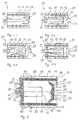
- FIG. 1.1shows a schematically simplified Representation of an embodiment of an inventive Boiler 11 '.
- a housing 13is from a heat exchanger 15 divided into a combustion chamber 17 and an exhaust gas chamber 19.
- a flame tube 23is on an end face of the combustion chamber 17 arranged and from the flame tube 23 strikes the flame axially 25.
- supply airflows through a mixing tube 21 into the flame tube 23, burns in the flame 25 and flows as hot Combustion gas or flue gas through passages in the Heat exchanger 15 in the exhaust chamber 19 (arrows). From there The flue gas leaves the exhaust gas space 19 by means of one in FIG. 1 not shown opening in the housing 13.
- Figure 1.2shows a variant of this, in which in a boiler 11 " Closing member 27, the combustion chamber 17 limited in length.
- FIG. 1.3shows a simplified variant of the Figure 1.2, in which the heat exchanger 15, the exhaust chamber 19th does not separate from the outflow chamber 29, but only that Combustion chamber 17 envelops. In Figure 1.2 and Figure 1.3 is by Arrows indicate how exhaust gas recirculates into the flame tube 23 becomes.
- 1.4shows a boiler 11 "" in which Boiler room in addition to the final organ 27 Closing member 27 'is arranged, which is a Recirculation chamber 33, so that recirculating Exhaust gas from the combustion chamber 17 through the heat exchanger 15 in the exhaust chamber 19 and again through the heat exchanger 15 through into the recirculation chamber 33 and from there through recirculation openings in the flame tube 23 this is sucked in.
- FIG. 2shows a section through a Embodiment of a boiler 11 in turn Heat exchanger 15, combustion chamber 17 and exhaust chamber 19.
- the flame tube 23is arranged in the combustion chamber 17, which recirculation openings 35 and a flame opening 37 having.
- the heat exchanger 15is made of tubes 40 with a flat Cross section formed, which are wound helically. The tubes 40 are spaced from each other so that in the space 41 between the pipes 40 the exhaust gas Can flow through heat exchanger 15.
- the heat exchanger 15consists of individual elements 43, which are parallel and / or are connected in series to an inlet or outlet.
- the A deflection part 39is arranged opposite the flame opening 37. This deflection part 39 forms a closure member 27 or is connected to a closure member 27.
- the closing body 27sits between two tubes 40 or between two elements 43, so that the hot exhaust gas through the spaces 41 from the combustion chamber 17 into the exhaust chamber 19 and from there again between the pipes 40 into the outflow chamber 29 must flow.
- the exhaust gascan then flow out of the outflow chamber 29 through the opening 31 into a fireplace or a Step over the exhaust pipe.
- the deflection part 39forms on the axis 45 of the Flame tube 23 or the boiler 11 an increase 47, which opposes the flame and divides it symmetrically.
- the Flameis through the deflection channel 49 in one of the original direction of flame opposite direction deflected and strikes between the flame tube 23 and the Heat exchanger tubes 40 back against the flame root. This creates an approximately cylindrical flame body of about double the flame tube diameter and the hot exhaust gases are through the entire length of the combustion chamber 17 Gaps 41 conveyed between the tubes 40 where an exchange of energy with that flowing in the tubes 40 Heat transfer medium takes place.
- the deflection part 39is basin-shaped and sits with its bottom 49 near that opposite the flame tube Front of the housing 13.
- the outer pool rim 51closes almost flush with the outer channel edge 53 of the Deflection channel 49 between the heat exchanger tubes 40 to this and the pool wall 55 runs obliquely from the edge 51 of the Heat exchanger tubes 40 away, so that none of the tubes 40 through the depth claimed by the deflection part 39 is covered.
- the the space occupied by the basin-shaped deflection part 39opens up Cost of the outflow chamber 29, which thereby necessary minimum dimension is reduced.
- the combustion chamber 17this opposed by this form of closing body 27 the outflow chamber 29 extended. So that the length of the boiler room can be minimized.
- a cover 57is arranged, which is connected to the housing 13 is screwed.
- the cover 57has an opening 59 the inside of which is a baffle plate or cover 61 which the flame tube 23 is attached.
- an annular disc 63arranged, which consists of a refractory, porous or felt-like material and therefore an insulating It has an effect on both heat and sound.
- the deflecting part 39has a structure and thus the same effect.
- the flame tube 23is located near the baffle plate 61 Recirculation openings 35 through which exhaust gas from the Space 65 between heat exchanger 15 and flame tube 23 in the Flame tube to be recirculated.
- the exhaust gas encased in Flame tube 23a centrally let air flow. Thereby the flame tube is immediately after the ignition of a flame hot exhaust gas and immediately becomes hot itself.
- an oil nozzle 67is provided which the fuel through the central air flow into the Exhaust jacket sprays. The fuel evaporates in the exhaust jacket. The vaporized fuel is now together with the exhaust gas swirled in the air. The flame burns blue because of the whole Fuel is gasified before flame formation.
- the same burner headcan be used for gas operation. Only the gaseous fuel is added to the air, preferably on the vacuum side in the fan.
- the flame tube 23becomes hot and transfers a certain amount of energy to the heat exchanger 15 by radiation. This effect is desirable, especially because blue-burning flames otherwise emit little radiant energy.
- the exhaust gas valuesare very low in both operating modes:
- the NO X emissionsare below 60 mg / kW in the case of an oil fire and below 20 mg / kW in the case of a gas fire.
- the CO valuesare below 16 mg / kW.
- FIGs 3 and 4show a further embodiment of a boiler according to the invention.
- Figure 3is a Longitudinal section
- Figure 4is a cross section of the same boiler.
- This boiler 11"is the closing member 27, for example as a simplified deflecting part without a specific shape designed.
- boiler 11 2shows a flame chamber jacket 69 on the combustion chamber side of the Heat exchanger 15 arranged in the combustion chamber 17.
- the Flame chamber jacket 69points to its cylindrical jacket Slits 71 and baffles 73, which are called Flue gases from the inner area of the combustion chamber 17 released and in a flow rotating about axis 45 through the spaces 41 between the tubes 40 of the Conduct heat exchanger 15 (arrows in Fig. 4).
- the flamenow strikes between the flame tube 23 and the flame chamber jacket 69 back to the flame tube side end of the housing 13.
- the flame chamber jacketdirects the exhaust gases into a spiral Movement around.
- the flame chamber jacket 69is a Protection for the heat exchanger 15. It protects the heat exchanger 15 largely before direct flame contact. That is why Flame chamber jacket at its front end, near that Closing member 27 or the deflecting part 39 closed and has no slots 71 through which they are not total deflected flame to the tubes 40 of the heat exchanger 15 could get.
- the screw turns 77 of the heat exchanger 15are included a straight connector 79 (Fig. 4) on both sides to a Lead 81 or a lead 83 connected.
- the individual heat exchanger elements 43consist of four Windings of a tube 40 with a flat cross section and are in parallel to the lead 81 and the lead 83 connected. Bulges in the pipe wall (not shown) keep a distance between the tubes 40 of turns 77.
- FIG. 5shows a burner head 111 for liquid Fuels, with a baffle plate 113, which is not in a Wall of a combustion chamber 112 shown is mountable.
- a flame tube 115with a 1: 2 diameter to length ratio arranged.
- a lance or nozzle 119is arranged.
- the fasteners for the nozzle 119 and the baffle plate 113together form e.g. an aperture unit, as described, for example, in EPA 0 650 014 is described.
- the nozzle head 123is centered in an orifice insert 125.
- the spray opening 121 of the nozzle 119lies in the plane of the baffle plate 113 or Aperture insert 125.
- the aperture insert 125is on the Baffle plate 113 attached and covers except for an annular Air opening 129 around nozzle head 123, opening 127 in the baffle plate 113.
- the annular air opening 129takes an area of approximately 8% of the cross-sectional area of the flame tube 115 a.
- the air opening 129is also swirling Guides 131 equipped. These guide surfaces 131 are radially aligned and are opposite the flame tube axis 117 and flow direction 114 inclined so that through the Air opening 129 flowing air rotating about axis 117 is transferred.
- the fins or guide surfaces 131are made made in one piece with the panel insert 125 (Fig. 7 and 8th). In their manufacture and alignment, they are up to a roughly twice the material thickness Connection 132 from the panel insert plate 134 cut out or punched and then opposite the Aperture insert plane rotated by 60 to 88 degrees. Here are on the most deformable places due to the twisting of the connections the lengths of the deforming sheet edges enlarged by round cutouts (136 in FIG. 7) by one Prevent cracking.
- the flame tube 115is with links 133 on the Baffle plate 113 attached.
- the links 133are formed in one piece with the wall 139 of the flame tube 115, protrude over the baffle plate end of the flame tube 115 out and are through slots in the baffle plate 113th put through. Be upstream of the baffle plate 113 the connectors 133 twisted after plugging together, so that a firm connection between baffle plate 113 and Flame tube 115 is formed.
- the connecting links 133have a stepped, themselves tapered silhouette on.
- Paragraphs 137 in the stairsare on the flame tube side of the baffle plate 113 and thus define the opening width of the recirculation slot 135. Exhaust gas becomes through this recirculation slot 135 along the baffle plate 113 and the aperture insert 125 in the Flame tube 115 sucked to soot this area to prevent.
- a favorable opening widthis around 1 mm.
- the flame tube 115has recirculation openings 139 through which the exhaust gas through the Vacuum, which is downstream of the baffle plate 113 due to the Air flow is created, is sucked in.
- the openings 139can but also in a different number and / or other form.
- the flame tube 115has an inner diameter of about 80 mm and a length of about 160 mm. At the The combustion chamber 112 facing the end of the flame tube 15 is this constricted. The constriction 141 narrows the Flame outlet opening 143 opposite Flame tube cross section. The edge area 145 of the flame tube 115 is round inward to form the constriction 141 turned.
- the ignition electrodes 147are near the periphery of the Flame tube 115 with ceramic insulation pieces 149 through the baffle plate 13 and protrude with their ends 151 into the flame tube 115.
- the ignition point 153is in a distance from the baffle plate 113 of about 2/5 of the length of the flame tube 115.
- the fuelis the shortest route through the Air flow sprayed through, shown with broken lines 172.
- the cone shell of the sprayed Fuelhas an angle between 60 and 90 degrees.
- the nozzlepreferably has a conical jacket characteristic 80 degrees. Gasified in an area 173 of the exhaust jacket 167 the fuel and is by vortex 175 in the exhaust jacket 167th mixed with the exhaust gas. Because upstream of the gasification zone 173 there is no gasified fuel that could burn, and on the short penetration path that the fuel must travel through airflow 169 which Fuel does not start to burn becomes practical All fuel in gas jacket 167 gasifies and arrives only in a gasified form with the air in a reaction triggering contact.
- Gasified fuelis thus in vortices 171 the exhaust gas swirls with the air and burns first in the area of these vertebrae 171 cool and low in pollutants.
- the flamebegins in its root region 177 at the end of the first third of the flame tube 115.
- the flame rootis annular between exhaust jacket 167 and air flow 169 embedded.
- the ends in the last third of the flame tubecentral air flow 169 in the center of the flame and cools it.
- the thickness of the jacket 167is decreasing downstream because the exhaust gas / fuel vapor mixture is on this route mixed with the air.
- the fuel vaporis about two thirds of the flame tube length fed to the flame.
- the Flamethus has an annular and elongated Root area and is out of the cladding area 167 nourished.
- the casing zone 167becomes through the constriction 141 limited downstream.
- the gas in the jacket area 167is at Flowing out of the flame tube 115 hindered. A swirl this favors the two media.
- the exiting Flamesticks to the flame tube.
- burner head 111 'is for gas and are different zones during the combustion of gaseous Fuel shown schematically.
- the burner head 111 'corresponds essentially to the burner head 111 for liquid Fuel.
- a perforated plate 157is in front of the baffle plate 113 in the direction of flow however, a perforated plate 157 at a distance from the baffle plate 113 arranged.
- the perforated plate 157has an opening 158, through which the displacement body or the oil nozzle 119 pushes through.
- the holesare arranged around it which cause a pressure drop to kick back to prevent the flame into the feed channel 155.
- At the Supply duct 155is a fuel supply and a blower arranged (both not shown).
- the flamebegins in its root area 177 in the first Third of the flame tube 115.
- the flame rootis ring-shaped between exhaust jacket 167 and air / fuel flow 169 embedded.
- the central stream 169ends in the center of the Flame and cool it.
- the thickness of the sheathis 167 decreasing downstream because the exhaust gas is on this System mixed with the air / fuel mixture.
- the Fuelburns quietly and is low in pollutants.
- the gas burnerworks practically regardless of the shape of the furnace. It is particularly suitable for compact firing systems with short firing rooms.
- the burneris not only suitable for burning gas.
- the burnerachieves exhaust gas values for NO x below 60 mg / kW with liquid fuels.
Landscapes
- Engineering & Computer Science (AREA)
- Chemical & Material Sciences (AREA)
- Combustion & Propulsion (AREA)
- Mechanical Engineering (AREA)
- General Engineering & Computer Science (AREA)
- Physics & Mathematics (AREA)
- Thermal Sciences (AREA)
- Combustion Of Fluid Fuel (AREA)
- Gas Burners (AREA)
Abstract
Description
Translated fromGermanDie vorliegende Erfindung betrifft einen mit einemBrenner ausgerüsteten Heizkessel oder Durchlauferhitzer, miteinem einen Kesselraum umhüllenden Gehäuse, einemmantelförmigen Wärmetauscher, welcher den Kesselraum in eineBrennkammer und eine Abgaskammer aufteilt und über dieMantelfläche verteilt Durchlässe für heisse Verbrennungsgaseaufweist, und einem in der Brennkammer angeordnetenBrennerkopf, gemäss Oberbegriff des Patentanspruchs 1.The present invention relates to aBurner-equipped boiler or instantaneous water heater, witha casing enclosing a boiler room, ajacket-shaped heat exchanger, which converts the boiler room into aCombustion chamber and an exhaust chamber split and over theThe lateral surface distributes passages for hot combustion gaseshas, and one arranged in the combustion chamberBurner head according to the preamble of patent claim 1.
In derfranzösischen Patentschrift Nr. 93 00498sind eine Reihe von Anordnungen von Heizkesselnaufgezeichnet, welche einige der oben angeführten Merkmaleaufweisen. Diese Heizkessel sind jedoch auf Gasbrenner ausgerichtet,welche einen stirnseitig verschlossenen, zylindrischen Mantelaufweisen, auf dessen Mantelfläche verteilt eine Vielzahl vonFlammöffnungen angeordnet sind. Ein solcher Gas-Heizkesseloder Durchlauferhitzer ist sehr platzsparend und benötigtkeinen separaten Heizungsraum.In theFrench Patent No. 93 00498are a series of arrangements of boilersrecorded some of the features listed aboveexhibit. However, these boilers are designed for gas burners,which has a cylindrical jacket that is closed at the endhave distributed on the lateral surface of a plurality ofFlame openings are arranged. Such a gas boileror instantaneous water heater is very space-saving and requiredno separate boiler room.
Schon lange besteht ein Bedürfnis nach einer derartplatzsparenden Heizanlage, welche mit dem Brennstoff Ölbetrieben werden kann. Denn ein Nachteil des Brennstoffs Gasist, dass seine Vorrathaltung bedeutend aufwendiger ist, alsdie Vorrathaltung von Öl. So ist eine Gasfeuerung entwederauf einen teuren Drucktank oder einen Anschluss an einVerteilnetz für Gas angewiesen, wogegen Öl bereits inTausenden von installierten Tanks problemlos und ingenügender Menge vor Ort gelagert wird. Auch die Versorgung bzw. das Auffüllen des Öltanks mit Öl ist wesentlicheinfacher und weniger gefährlich als beim Gas.There has been a need for such a long timespace-saving heating system, which uses the fuel oilcan be operated. A disadvantage of gas as a fuelis that its inventory is significantly more expensive thanthe supply of oil. So is gas firing eitherto an expensive pressure tank or a connection to oneDistribution network for gas, whereas oil is already inThousands of tanks installed easily and insufficient quantity is stored on site. Also the supplyor filling the oil tank with oil is essentialeasier and less dangerous than with gas.
GB-A-792 747 offenbart einen Heizkessel mit einemKesselraum, welcher durch einen Wärmetauscher aus einemspezielle gewundenen Rohr in eine vom Wärmetauscher umwundeneFeuerkammer und eine den Wärmetauscher umgebende Abgaskammeraufteilt. Gegenüber einem stirnseitig angeordneten,Schamotte-Flammtopf, in welchem für die Inbetriebnahme desHeizkessels ein nicht dargestellter Brennerkopf anzuordnenist, ist eine Kopfanordnung ausgebildet, an welcher dieheissen Gase umgelenkt und verwirbelt werden. Durch dieVerwirbelung geraten unverbrannte Gase von der Peripheriezurück in die zentrale Flamme. Der Zustrom des frischentzündeten Luft/Brennstoffgemisches in die Brennkammererzeugt einen Überdruck, mit welchem die Abgase Öffnungenzwischen den Wicklungen des Wärmetauscherrohres hindurch ineinen Ringkanal ausserhalb des Wärmetauschers gedrängtwerden. Die Abgase können dabei in der Nähe der Kopfanordnungin einen ersten Ringkanal gelangen, in diesem zurBrennerseite strömen und in einem zweiten äusseren Ringkanalwieder zurück. In einem einfacheren Ausführungsbeispielgelangen sie innerhalb der Brennkammer zur Brennerseite, undtreten dort durch die Öffnungen in den Ringkanal. In diesemRingkanal strömt das Abgas wieder in die andere Richtungeinem Kamin zu. Ein Brennerkopf ist innerhalb des Flammtopfesanzuordnen, welcher den Wärmetauscher vor der Strahlungswärmeder Flamme und des Brennerkopfes schützt. Eine Rezirkulationdes Abgases in die Flamme ist lediglich im Kesselraumausserhalb des Flammtopfes vorgesehen. Mit einem solchenKessel lassen sich deshalb Brennstoffe lediglich mit hohenAbgasemissionswerten verbrennen.GB-A-792 747 discloses a boiler with oneBoiler room, which is made up of a heat exchangerspecial coiled pipe into a pipe wrapped by the heat exchangerFire chamber and an exhaust gas chamber surrounding the heat exchangerdivides. Opposite an arranged on the front,Fireclay flame pot, in which for the commissioning of theArrange a boiler head, not shown, in the boileris a head assembly is formed on which thehot gases are redirected and swirled. Through theTurbulence gets unburned gases from the peripheryback to the central flame. The influx of freshignited air / fuel mixture into the combustion chambercreates an overpressure with which the exhaust gases openingsbetween the windings of the heat exchanger tube ina ring channel outside the heat exchangerbecome. The exhaust gases can be close to the head arrangementget into a first ring channel, in this toFlow on the burner side and in a second outer ring channelback again. In a simpler embodimentthey reach the burner side within the combustion chamber, andstep through the openings into the ring channel. In thisThe flue gas flows in the other direction againto a fireplace. A burner head is inside the flame potto arrange which is the heat exchanger before the radiant heatprotects the flame and the burner head. A recirculationof the exhaust gas in the flame is only in the boiler roomprovided outside the flame pot. With oneBoilers can therefore only use high fuelsBurn exhaust emissions.
Aus der DE-A-32 12 006 ist ein Heizkessel gemäss demOberbegriff des Patentanspruchs 1 bekannt. Der Kessel ist miteinem senkrecht stehenden Wendelrohr als Wärmetauscherversehen. Oberseitig des Kessels ist ein Brennerkopf einesSturzbrenners angeordnet. Gegenüber der Feueröffnung des Flammbechers des Sturzbrenners ist eine konkaveSchamottplatte angeordnet. Um die Schamottplatte und diezwischen Feueröffnung und Schamottplatte sich erstreckendeUmkehrbrennkammer ist der Wärmetauscher angeordnet, welchereinen um den Wärmetauscher herum angeordneten, ringförmigenHeizgaszug von der Brennkammer trennt. Durch dieSchamottplatte werden die heissen Gase zurück zum Brennerkopfumgelenkt. Die Windungen des Wendelrohres sind in einemmittleren Bereich eng anliegend. Durch zunehmende Öffnungenzwischen den Endwindungen des Wendelrohrs gelangt das Gas inden äusseren Heizgaszug, wo es wieder nach unten und nochmalsdurch den Wärmetauscher hindurch in ein Abgasrohr geleitetwirdFrom DE-A-32 12 006 a boiler according to theThe preamble of claim 1 is known. The boiler is witha vertical spiral tube as a heat exchangerMistake. On the top of the boiler is a burner headFall burner arranged. Opposite the fire opening of theThe lint burner's flame cup is a concave oneFirebrick arranged. To the fireclay and theextending between the fire opening and the fireclay panelReverse combustion chamber, the heat exchanger is arranged, whichan annular one arranged around the heat exchangerSeparates the hot gas flue from the combustion chamber. Through theFireclay is used to return the hot gases to the burner headredirected. The turns of the spiral tube are in onemiddle area tight. Through increasing openingsthe gas enters between the end turns of the helical tubethe outer hot gas flue, where it is down again and againpassed through the heat exchanger into an exhaust pipebecomes
Nachteilig an diesem Heizkessel ist, dass die Temperaturdes Heizgases im äusseren Heizgaszug noch derart hoch ist,dass Strahlungswärme von einem den Heizgaszug umschliesendenund durch die Heizgase bestrichenen Schamotterohr auf denWärmetauscher übertragen werden kann.The disadvantage of this boiler is that the temperaturethe heating gas in the outer heating gas flue is still so highthat radiant heat from one that surrounds the heating gas flueand on theHeat exchanger can be transferred.
Es ist deshalb Aufgabe der Erfindung, eineFeuerungsanlage zu schaffen, welche mit einem Ölbrennerbetrieben werden kann, ohne dass sie deswegen grösser alseine Gasfeuerungsanlagen ist. Zudem soll die Heizanlage miteinem Öl- oder Gasbrenner betrieben werden können. Weiter istes Aufgabe der Erfindung, eine Feuerungsanlage zu schaffen,die sich durch sehr niedrige Abgaswerte und kleineWärmeverluste und auch einen niedrigen Geräuschpegelauszeichnet.It is therefore an object of the invention toTo create firing system, which with an oil burnercan be operated without being larger thanis a gas firing system. In addition, the heating system shouldan oil or gas burner can be operated. Is furtherit is the object of the invention to create a furnace,which is characterized by very low emissions and smallHeat loss and also a low noise leveldistinguished.
Erfindungsgemäss wird dies durchdie Kennzeichenden Merkmale des Anspruchs 1erreicht.According to the invention, this is achieved bythe characterizing features of claim 1reached.
Ein Vorteil des erfindungsgemässen Heizkessels liegtdarin, dass er mit Brennern beheizt werden kann, welche einelanzenförmige Flamme aufweisen. Eine solche Flamme benötigtnormalerweise einen in Flammenrichtung langgezogenenFeuerraum. Ein erfindungsgemäss angeordnetesFlammenumlenkteil ermöglicht jedoch, die Länge desFeuerraumes wesentlich zu verkürzen. Das Umlenkteil lenkt dieFlamme zurück zu ihrem Ausgangspunkt und verkürzt denKesselraum damit auf etwa halbe Länge. Dadurch ist dieBrennkammer mit einer Flamme fast ausgefüllt, welche auseinem Flammrohr hinaus in die eine Richtung und am Umlenkteilumgelenkt in die entgegengesetzte Richtung brennt. Hierbeibildet der hintere Teil der Flamme eine axiale Kernströmungund der vordere Teil der Flamme eine um die Kernströmung herum angeordnete gegenläufige Mantelströmung. DieRückführung der Flamme zu ihrer Wurzel hat weiter denVorteil, dass sofort nach Entfachen der Flamme um dasFlammrohr herum heisse Gase vorliegen, welche für dieVerbesserung des Kaltstartverhaltens genutzt werden können.Von Vorteil ist weiter, dass durch das Wenden der Flamme derFeuerungsraum besser ausgenutzt ist und kompakter gestaltetwerden kann, als bei langer, dünner Flammenform. Insbesondereist die ganze Länge des Feuerraumes praktisch gleichmässigzur Wärmeübertragung auf ein Wärmetauschermedium geeignet,weil der Brennkopf von der Flamme ummantelt ist.One advantage of the boiler according to the invention isin that it can be heated with burners, which onehave lance-shaped flame. Such a flame is neededusually one elongated in the direction of the flameFirebox. An arranged according to the inventionFlame deflecting part, however, allows the length of theShorten the combustion chamber significantly. The deflecting part directs theFlame back to its starting point and shorten itBoiler room about half the length. This is theCombustion chamber almost filled with a flame, which comes froma flame tube in one direction and on the deflection partredirected in the opposite direction burns. Herethe rear part of the flame forms an axial core flowand the front part of the flame one around the core flowopposite mantle flow arranged around. TheReturning the flame to its root has continuedAdvantage that immediately after lighting the flame around theThere are hot gases around the flame tube, which are suitable for theImprovement of the cold start behavior can be used.Another advantage is that by turning the flameFurnace is better used and more compactthan with a long, thin flame shape. In particularthe entire length of the firebox is practically uniformsuitable for heat transfer to a heat exchange medium,because the burning head is covered by the flame.
Vorteilhaft weist der Wärmetauscher bei oder nahewenigstens einem Ende ein Abschlussorgan auf, welches dieBrennkammer in der Längsrichtung begrenzt. Dadurch istzusätzlich zur Abgaskammer um den Wärmetauscher herum auchnoch eine weitere Kammer gebildet, in welche Abgas aus derAbgaskammer fliesst. Dieses Abgas ist nun durch denWärmetauscher bereits gekühlt und kann zur Kühlung der Flammeteils in das Flammrohr rezirkuliert und teils durch ein Kaminabgelassen werden. Vorteilhaft teilt ein Abschlussorgan aufseiner der Brennkammer abgewandten Seite vom Kesselraum einemit einem Kamin verbindbare Ausströmkammer ab. Eine solcheAusströmkammer liegt axial im Kessel. Dadurch nimmt sie dasRauchgas aus der Peripherie gleichmässig auf. EinseitigeBelastungen des Wärmetauschers können damit vermieden werden.Vorteilhaft teilt ein Abschlussorgan vom Kesselraum eineRezirkulationskammer ab. Durch diese Rezirkulationskammerkann gekühltes Abgas zur Kühlung der Flamme ins Flammrohrrezirkuliert werden. Die Rezirkulationskammer kanngleichzeitig auch die Ausströmkammer sein. Vorteilhaft istdie durch ein Abschlussorgan abgeteilte Abgasausströmkammeroder/und die Rezirkulationskammer vom Wärmetauscherummantelt. Dadurch wird das in diese Kammern einströmendeAbgas zusätzlich gekühlt, bevor es den Heizraum verlässt,bzw. seine kühlende Aufgabe wahrnimmt. Das Abgas wird durchden zweimaligen Kontakt mit dem Wärmetauscher bis auf etwa 80 Grad abgekühlt, und dies selbst im Dauerbetrieb unterVolleistung. Dadurch kann das Rauchgas nach dem Kessel direktin ein Kunststoffkamin abgelassen werden.The heat exchanger advantageously has at or nearat least one end of a final organ, which theCombustion chamber limited in the longitudinal direction. This isin addition to the exhaust gas chamber around the heat exchangerformed yet another chamber in which exhaust gas from theExhaust chamber flows. This exhaust gas is now through theHeat exchanger is already cooled and can be used to cool the flamepartly recirculated into the flame tube and partly through a chimneybe drained. A closing body advantageously dividesits side facing away from the combustion chamber from the boiler roomoutflow chamber connectable with a chimney. SuchOutflow chamber lies axially in the boiler. So she takes itFlue gas from the periphery evenly. UnilateralLoads on the heat exchanger can thus be avoided.A closing organ from the boiler room advantageously divides oneRecirculation chamber. Through this recirculation chamberCooled exhaust gas can be used to cool the flame into the flame tubebe recirculated. The recirculation chamber canalso be the outflow chamber. It is advantageousthe exhaust gas discharge chamber partitioned off by a closing elementor / and the recirculation chamber from the heat exchangerencased. As a result, what flows into these chambers becomesExhaust gas additionally cooled before it leaves the boiler roomor performs its cooling task. The exhaust gas is throughthe double contact with the heat exchanger up to about 80Degrees cooled, even under continuous operationFull performance. This allows the flue gas to go directly to the boilerbe drained into a plastic fireplace.
Vorteilhaft weist das Abschlussorgan zwischenBrennkammer und Abgasausströmkammer eine Ausbuchtung zurAbgasausströmkammer hin auf, damit die Brennkammer verlängertwerden kann und die Ausströmkammer nicht unnötig viel Platzbeansprucht. Zweckmässigerweise wird durch eine solcheAusbuchtung die Wärmetauscherfläche um dieAbgasausströmkammer herum im Verhältnis zu deren Volumengross gehalten.The closing body advantageously points betweenCombustion chamber and exhaust gas outflow a bulge forExhaust gas outflow chamber open to extend the combustion chamberand the outflow chamber does not take up too much spaceclaimed. Expediently through suchBulge the heat exchanger area around theExhaust gas outflow chamber in relation to its volumekept large.
Vorteilhaft bildet das Flammenumlenkteil einAbschlussorgan, damit die Anzahl der benötigten Teilereduziert werden kann. Zudem hat die Anordnung desUmlenkteils mit Abstand zur Gehäusewand auch akustischeVorteile. Zweckmässigerweise ist dieses Abschlussorgan oderFlammenumlenkteil zur Ausströmkammer hin ausgebuchtet. In derAusbuchtung geschieht zweckmässigerweise die Umlenkung derFlamme, ohne dass dabei Wärmetauscherelemente beteiligt sind,und die gesamte Wärmetauscherfläche kann genutzt werden, weildas Umlenkteil keine Durchlässe für heisses Rauchgasverdeckt. Zweckmässigerweise weist das Flammenumlenkteileinen auf der Flammenachse angeordneten, der Flammeentgegenstehenden Flammenteiler und um diesen herum eineringförmige Umlenkrinne auf. Der Flammenteiler teilt dieFlamme auseinander und die Umlenkrinne führt die Flammenteileso, dass deren Strömungsrichtung um 180° gewendet wird. DieUmlenkrinne ist vorteilhaft umlaufend gleichmässigausgestaltet, so dass die Flamme auch nach der Umlenkung einegleichmässige Form aufweist.The flame deflecting part advantageously formsClosing organ, so the number of parts requiredcan be reduced. In addition, the arrangement of theDeflection part at a distance from the housing wall also acousticBenefits. This closing body is expediently orFlame deflection part bulged out towards the outflow chamber. In theBulge expediently occurs the deflection of theFlame without involving heat exchanger elements,and the entire heat exchanger area can be used becausethe deflecting part has no openings for hot flue gascovered. The flame deflecting part expediently hasone on the flame axis, the flameopposing flame dividers and one around themannular deflection channel. The flame divider divides theFlame apart and the deflector guides the flame partsso that their flow direction is turned through 180 °. TheDeflection channel is advantageously uniform all rounddesigned so that the flame even after the deflectionhas a uniform shape.
Vorteilhaft besteht der Mantel des Wärmetauschers ausmit Zwischenraum nebeneinander aufgereihten Rohren, welchedie Brennkammer umfangend angeordnet und an eine Zu- und eineAbleitung angeschlossen sind. Zweckmässigerweise sind dieWärmetauscherrohre schraubenförmig gewickelt. Ein solcherwärmetauschermantel ist einfach in der Herstellung, weist eine grosse Oberfläche und Durchlässe zwischen den Rohrenauf. Rohre können zusätzlich, im Vergleich zu Gussteilen,eine geringere Wandstärke und damit eine dynamischereWärmeübertragung aufweisen, was sich durch eine höhereLeistung bei geringem Platzbedarf bemerkbar macht.Vorteilhaft ist der Mantel des Wärmetauschers aus einerMehrzahl von Wärmetauschereinheiten zusammengefügt. Dieeinzelnen Wärmetauschereinheiten weisen dadurch gegenübereinem Wärmetauscher mit einem einzigen, dafür umso längerenRohr, eine kleinere Rohrleitungslänge auf, wodurch dieDurchflussgeschwindigkeit erhöht werden kann.The jacket of the heat exchanger advantageously consists ofwith space next to each other, whichthe combustion chamber arranged extensively and to a feed and aDischarge are connected. These are expedientlyHeat exchanger tubes wound helically. Such aheat exchanger jacket is easy to manufacture, exhibitsa large surface and passages between the pipeson. In addition, compared to castings, pipes cana smaller wall thickness and thus a more dynamic oneHave heat transfer, which is characterized by a higherPerformance noticeable in a small footprint.The jacket of the heat exchanger is advantageous from aA plurality of heat exchanger units put together. TheIndividual heat exchanger units face each othera heat exchanger with a single one, but all the longerPipe, a smaller length of pipe, causing theFlow rate can be increased.
Zweckmässigerweise sind die Wärmetauschereinheitendeshalb parallel an die Zu- und Ableitung angeschlossen. MitVorteil werden Wärmetauschereinheiten gemäss den imfranzösischen Patent Nr. 93 00498 beschriebenenWärmetauscherelementen angewendet. Diese zeichnen sich unteranderem durch einen flachgedrückten Rohrquerschnitt aus,wodurch die Austauschoberfläche gegenüber rundenQuerschnitten zusätzlich vergrössert wird. Unter anderembesteht ein wesentlicher Vorteil bei'der Verwendung dieserWärmetauschereinheiten auch darin, dass ihre Produktionbereits für Gas-Durchlauferhitzer läuft und sie deshalb inausgezeichneter Qualität auf dem Markt käuflich vorliegen.The heat exchanger units are expedienttherefore connected in parallel to the inlet and outlet. WithHeat exchanger units according to the inFrench Patent No. 93 00498Heat exchanger elements applied. These stand outother by a flattened pipe cross-section,which rounds out the exchange surfaceCross sections is also enlarged. Amongst other thingsthere is a significant advantage to using themHeat exchanger units also in that their productionis already running for gas water heaters and therefore inexcellent quality available on the market.
Vorteilhaft ist der Brenner für Abgasrezirkulationausgerüstet, um die heute vorgeschriebenen Abgaswerte,insbesondere auch bei häufigem Kaltstart, zu unterschreiten.Wenn auch Gasbrenner im erfindungsgemässen Kessel Verwendungfinden können, so ist der Brenner doch vorteilhaft einÖlbrenner, weil Öl in einfachen Tanks bevorratet werden kannund diese einfach nachgefüllt werden können. Die Abhängigkeitvon einem Leitungsnetz kann so vermieden werden. DieHandhabung von Öl ist zudem wesentlich weniger gefährlich alsdie Handhabung von Gas, welches, so es nicht durch ein Netzverteilt wird, unter Druck in entsprechende Drucktanksabgefüllt werden muss.The burner is advantageous for exhaust gas recirculationequipped to meet the exhaust gas values prescribed today,especially in the case of frequent cold starts.Even if gas burners are used in the boiler according to the inventioncan find, so the burner is advantageousOil burners because oil can be stored in simple tanksand these can easily be refilled. The dependencefrom a pipeline network can thus be avoided. TheHandling oil is also much less dangerous thanthe handling of gas which, so it is not through a networkis distributed under pressure in appropriate pressure tanksmust be filled.
Vorteilhaft ist der Brenner umstell- oder umschaltbarauf Gasbetrieb. Wenn der Brennerkopf sowohl für Öl wie fürGas geeignet ist, können diese beiden Medien alternativ, mitgeringem zusätzlichem Installationsaufwand, in der gleichenAnlage genutzt werden. Dies hat die Vorteile, dass z.B. aufPreisentwicklungen reagiert werden kann, dass eine höhereSicherheit gegenüber Lieferengpässen vorliegt oder durchInstallation eines provisorischen Öltanks auf eineprojektierte Erstellung einer Gaszuleitung gewartet werdenkann, usw.The burner is advantageously switchable or switchableon gas operation. If the burner head for both oil and oilAlternatively, these two media can be used with gaslittle additional installation effort, in the samePlant can be used. This has the advantages that e.g. onPrice developments that can be responded to are higherSecurity against delivery bottlenecks exists or throughInstallation of a temporary oil tank on aprojected creation of a gas supply linecan, etc.
Vorteilhaft sprüht bei Ölbetrieb des Brenners eineÖldüse das Öl zum Verdampfen in in das Flammrohrrezirkuliertes Abgas und sind die Einlassöffnungen in dasFlammrohr für die Luft bzw. das Abgas derart ausgebildet,dass sich die Luft und das Abgas in einer hohlzylindrischenoder hohlkegelstumpfförmigen Wirbelzone vermischen. Das mitdem Abgas vermischte Öl ist dadurch vollständig verdampft,bevor es mit der Luft vermischt wird. Dadurch ergeben sichsehr vorteilhafte Abgaswerte und ein ausgezeichnetesStartverhalten des Brenners.One advantageously sprays when the burner is operated with oilOil nozzle to evaporate the oil into the flame tuberecirculated exhaust gas and are the inlet openings in theFlame tube for the air or the exhaust gas designed suchthat the air and the exhaust gas are in a hollow cylindricalor a frustoconical vortex zone. That withoil mixed with the exhaust gas has completely evaporated,before it is mixed with the air. This results invery advantageous exhaust gas values and an excellentStarting behavior of the burner.
Zweckmässigerweise ist bei Gasbetrieb des Brenners einZuluftkanal als Mischrohr für die Beimischung von gasförmigemBrennstoff ausgebildet. Vorteilhaft sind die Einlassöffnungenin das Flammrohr für das Brennstoff/Luft-Gemisch bzw, dasrezirkulierte Abgas derart ausgebildet, dass sich dasBrennstoff/Luft-Gemisch und das Abgas in einerhohlzylindrischen oder hohlkegelstumpfförmigen Wirbelzonevermischen. Durch diese ähnlichen Methoden bedingt, kann dasgleiche Flammrohr sowohl für Öl wie für Gas Verwendungfinden. Es können sogar die Öldüse bei Gasbetrieb,beziehungsweise die gaszuführenden Mittel bei Ölbetrieb inder Anlage verbleiben, so dass eine Zweimedien-Feuerunganlagemit einem einzigen Brenner vorliegt. Zusätzlich werden mitdiesen Brennern Abgaswerte von unter 60 mg NOx pro kW für Ölund unter 20 mg NOx bei Gas erreicht. Auch die CO-Werteliegen mit 16 mg/kW auf einem tiefen Niveau. Abgesehen davon wird mit diesem Brenner ein ausgezeichnetesKaltstartverhalten erzielt.When the burner is operated with gas, an air supply duct is expediently designed as a mixing tube for the admixture of gaseous fuel. The inlet openings in the flame tube for the fuel / air mixture or the recirculated exhaust gas are advantageously designed such that the fuel / air mixture and the exhaust gas mix in a hollow cylindrical or frustoconical vortex zone. Due to these similar methods, the same flame tube can be used for both oil and gas. The oil nozzle can even remain in the system during gas operation or the gas supply means during oil operation, so that there is a two-media firing system with a single burner. In addition, these burners achieve exhaust gas values of less than 60 mg NOx per kW for oil and less than 20 mg NOx for gas. The CO values of 16 mg / kW are also at a low level. Apart from this, excellent cold start behavior is achieved with this burner.
Vorteilhaft ist in der Brennkammer zwischen Brennrohr,bzw. umgelenkter Flamme und Wärmetauscher ein zylindrischerFlammraummantel angeordnet, welcher Durchlässe für heisseRauchgase aufweist. Dieser Flammraummantel gewährleistet einegleichmässige Verteilung der heissen Rauchgase auf denWärmetauscher und bildet einen Aschenfänger. Er schützt denWärmetauscher vor direktem Kontakt mit der Flamme. Dadurchkann der Abstand zwischen Flamme und Wärmetauscher sehr kleingehalten werden. Zusätzlich wirkt sich dieser Flammraummantelpositiv auf die Lärmdämmung aus. Vorteilhaft sind dieDurchlässe so angeordnet, dass die Rauchgase etwa tangentialaus dem Flammraummantel ausströmen, weil sie so in einergemeinsamen Drehrichtung geordnet den Wärmetauschermanteletwa tangential durchströmen. Dadurch ist dieWärmeübertragung gegenüber der Wärmeübertragung bei radialerDurchströmungsrichtung verbessert.It is advantageous in the combustion chamber between the combustion tubeor deflected flame and heat exchanger a cylindricalFlame chamber jacket arranged, which passages for hotHas smoke gases. This flame chamber jacket ensures oneeven distribution of the hot smoke gases to theHeat exchanger and forms an ash catcher. It protects theHeat exchanger before direct contact with the flame. Therebythe distance between the flame and the heat exchanger can be very smallbeing held. This flame chamber coat also has an effectpositive on noise insulation. They are advantageousPassages arranged so that the flue gases are approximately tangentialflow out of the flame chamber jacket because they are in onecommon direction of rotation ordered the heat exchanger jacketflow through tangentially. This is theHeat transfer versus radial heat transferFlow direction improved.
Vorteilhaft weist das Gehäuse den Einbau in einWandheizgerät oder Kücheneinschubgerät ermöglichendeAbmessungen auf. Das Gehäuse mit Luftzuleitung und Abgaskanalkann dazu eine Länge von bis zu ca. 50 cm aufweisen. Einekurze Ausführungsform kommt mit gut 30 cm Kessellänge aus.Damit kann auf einen eigenen Raum für diese Heizungverzichtet werden. Sie kann in einem Schrank untergebrachtwerden. Vorteilhaft ist eine Zuluftleitung im Gegenstrom umdas Rauchgasrohr angeordnet, damit die Luft durch die Abwärmeim Rauchgas vorgeheizt wird. Zweckmässigerweise ist dasGebläse neben dem Gehäuse angeordnet und ein Zuluftkanal vomGebläse auf eine Stirnseite des Gehäuses und an den Brennkopfgeführt, um die Länge oder Tiefe der Anlage möglichst kleinzu halten.The housing advantageously has an installation inEnabling wall heater or plug-in kitchen unitDimensions on. The housing with air supply and exhaust ductcan have a length of up to approx. 50 cm. Athe short version comes with a good 30 cm boiler length.This allows for a separate room for this heaterto be dispensed with. It can be stored in a closetbecome. A supply air line in counterflow is advantageousthe flue gas pipe arranged to allow the air to pass through the waste heatis preheated in the flue gas. This is expedientBlower arranged next to the housing and a supply air duct fromFan on one end of the housing and on the burner headled to the length or depth of the plant as small as possibleto keep.
Vorteilhaft sind an den Stirnseiten der Brennkammerfeuerfeste Platten mit labyrinthischer innerer Strukturangeordnet. Diese schützen die dahinterliegenden Metallteile,isolieren das Gehäuse gegenüber der Hitze der Flamme und dämmen die Schallemissionen des Brenners. Zweckmässigerweiseist eine Stirnseite des Gehäuses durch einen entfernbarenDeckel verschlossen. Vorteilhaft ist der Brenner am Deckelbefestigt. Dadurch ist der Kesselraum und der Brenner leichtzugänglich.Are advantageous on the end faces of the combustion chamberfireproof panels with a labyrinthine inner structurearranged. These protect the metal parts behind,isolate the housing from the heat of the flame anddampen the burner's noise emissions. Convenientlyis an end face of the housing by a removableLid closed. The burner on the lid is advantageousattached. This makes the boiler room and the burner lightaccessible.
Zweckmässigerweise sind wesentliche Gehäuseteileund/oder der Wärmetauscher aus austenitischem Edelstahlgefertigt, welcher resistent ist gegen die aggressiven Abgaseund Kondensate.Essential housing parts are expedientand / or the heat exchanger made of austenitic stainless steelmanufactured, which is resistant to the aggressive exhaust gasesand condensates.
Nachfolgend werden Ausführungsbeispiele der Erfindungunter Bezugnahme auf die Figuren beschrieben. Es zeigt:
- Fig. 1
- vier schematische Anordnungen von Heizkesseln,
- Fig. 2
- ein Ausführungsbeispiel eines erfindungsgemässenHeizkessels, im Längsschnitt,
- Fig. 3
- ein Ausführungsbeispiel eines erfindungsgemässenHeizkessels mit Flammraummantel, im Längsschnitt,
- Fig. 4
- ein Ausführungsbeispiel gemäss Figur 3, imQuerschnitt,
- Fig. 5
- den Öl-Brennerkopf im Längsschnitt,
- Fig. 6
- schematisch das Verbrennungsverfahren beiflüssigem Brennstoff,
- Fig. 7
- Aufsicht auf einen Blendeneinsatz mitausgeschnittenen, jedoch noch nicht verdrehtenFührungsflächen,
- Fig. 8
- Schnitt durch den Blendeneinsatz nach Fig. 7,wobei die Führungsflächen zur Drallerzeugungverdreht sind,
- Fig. 9
- den Gas-Brennerkopf im Längsschnitt undschematisch das Verbrennungsverfahren beiVerwendung von gasförmigem Brennstoff.
- Fig. 1
- four schematic arrangements of boilers,
- Fig. 2
- an embodiment of a boiler according to the invention, in longitudinal section,
- Fig. 3
- an embodiment of a boiler according to the invention with flame chamber jacket, in longitudinal section,
- Fig. 4
- an embodiment of Figure 3, in cross section,
- Fig. 5
- the oil burner head in longitudinal section,
- Fig. 6
- schematically the combustion process for liquid fuel,
- Fig. 7
- Supervision of a panel insert with cut out but not yet twisted guide surfaces,
- Fig. 8
- 7 through the diaphragm insert according to FIG. 7, the guide surfaces being twisted to generate swirl,
- Fig. 9
- the gas burner head in longitudinal section and schematically the combustion process when using gaseous fuel.
Figur 1.1 zeigt eine schematisch vereinfachteDarstellung einer Ausführungsform eines erfindungsgemässenHeizkessels 11'. Ein Gehäuse 13 wird von einem Wärmetauscher15 in eine Brennkammer 17 und eine Abgaskammer 19 aufgeteilt.Ein Flammrohr 23 ist auf einer Stirnseite der Brennkammer 17angeordnet und aus dem Flammrohr 23 schlägt axial die Flamme25. Zuluft strömt durch ein Mischrohr 21 in das Flammrohr 23,verbrennt in der Flamme 25 und strömt als heissesVerbrennungsgas oder Rauchgas durch Durchlässe imWärmetauscher 15 in die Abgaskammer 19 (Pfeile). Von dortverlässt das Rauchgas den Abgasraum 19 durch eine in Fig. 1nicht dargestellte Öffnung im Gehäuse 13. Figur 1.2 zeigteine Variante dazu, bei der in einem Heizkessel 11" einAbschlussorgan 27 die Brennkammer 17 in der Länge begrenzt.Figure 1.1 shows a schematically simplifiedRepresentation of an embodiment of an inventiveBoiler 11 '. A
Der Kesselraum ist dadurch in drei Zonen gegliedert: dieBrennkammer 17, die Abgaskammer 19 und eineAbgasausströmkammer 29. Die Abgase strömen nun aus derAbgaskammer 19 zuerst durch den Wärmetauscher 15 hindurch indie Abgasausströmkammer 29 und von dort durch eine Öffnung 31in ein Kamin. Figur 1.3 zeigt eine vereinfachte Variante derFigur 1.2, bei der der Wärmetauscher 15 die Abgaskammer 19nicht von der Ausströmkammer 29 trennt, sondern nur dieBrennkammer 17 umhüllt. In Figur 1.2 und Figur 1.3 ist durchPfeile angegeben, wie Abgas in das Flammrohr 23 rezirkuliertwird. In Figur 1.4 ist ein Kessel 11"" gezeigt, in dessenKesselraum zusätzlich zum Abschlussorgan 27 einAbschlussorgan 27' angeordnet ist, welches eineRezirkulationskammer 33 abteilt, so dass rezirkulierendesAbgas von der Brennkammer 17 durch den Wärmetauscher 15 indie Abgaskammer 19 und wieder durch den Wärmetauscher 15hindurch in die Rezirkulationskammer 33 gelangt und von dortdurch Rezirkulationsöffnungen im Flammrohr 23 hindurch indieses hineingesaugt wird.The boiler room is thus divided into three zones: the
Figur 2 zeigt in einem Schnitt durch einAusführungsbeispiel eines Kessels 11 wiederum denWärmetauscher 15, die Brennkammer 17 und die Abgaskammer 19.In der Brennkammer 17 ist das Flammrohr 23 angeordnet,welches Rezirkulationsöffnungen 35 und eine Flammöffnung 37aufweist. Der Wärmetauscher 15 ist aus Rohren 40 mit flachemQuerschnitt gebildet, welche schraubenförmig gewickelt sind.Die Rohre 40 sind mit Abstand zueinander angeordnet, so dassim Zwischenraum 41 zwischen den Rohren 40 das Abgas denWärmetauscher 15 durchströmen kann. Der Wärmetauscher 15besteht aus einzelnen Elementen 43, welche parallel und/oderin Serie an eine Zu- bzw. Ableitung angeschlossen sind. DerFlammöffnung 37 gegenüber ist ein Umlenkteil 39 angeordnet.Dieses Umlenkteil 39 bildet ein Abschlussorgan 27 oder istmit einem Abschlussorgan 27 verbunden. Das Abschlussorgan 27sitzt zwischen zwei Rohren 40 bzw. zwischen zwei Elementen43, so dass das heisse Abgas durch die Zwischenräume 41 vonder Brennkammer 17 in die Abgaskammer 19 und von dort wiederzwischen den Rohren 40 hindurch in die Ausströmkammer 29strömen muss. Von der Ausströmkammer 29 kann das Abgas danndurch die Öffnung 31 hindurch in ein Kamin oder eineAbgasleitung hinübertreten.Figure 2 shows a section through aEmbodiment of a
Das Umlenkteil 39 bildet auf der Achse 45 desFlammrohres 23 bzw. des Kessels 11 eine Erhöhung 47, welcheder Flamme entgegensteht und sie symmetrisch teilt. DieFlamme wird durch die Umlenkrinne 49 in eine derursprünglichen Flammenrichtung entgegengesetzte Richtungumgelenkt und schlägt zwischen dem Flammrohr 23 und denWärmetauscherrohren 40 gegen die Flammenwurzel zurück.Dadurch entsteht ein etwa zylindrischer Flammenkörper vonetwa doppeltem Flammrohrdurchmesser und die heissen Abgasewerden über die ganze Länge der Brennkammer 17 durch dieZwischenräume 41 zwischen den Rohren 40 hindurchgefördert, woein Energieaustausch mit dem in den Rohren 40 fliessendenWärmeträgermedium stattfindet.The
Das Umlenkteil 39 ist beckenförmig ausgebildet und sitztmit seinem Boden 49 nahe der dem Flammrohr gegenüberliegendenStirnseite des Gehäuses 13. Der äussere Beckenrand 51schliesst nahezu bündig mit dem äusseren Rinnenrand 53 derUmlenkrinne 49 zwischen den Wärmetauscherrohren 40 an diesean und die Beckenwand 55 läuft vom Rand 51 schräg von denWärmetauscherrohren 40 weg, so dass keines der Rohre 40 durchdie vom Umlenkteil 39 beanspruchte Tiefe abgedeckt wird. Dervom beckenförmigen Umlenkteil 39 beanspruchte Platz geht aufKosten der Ausströmkammer 29, welche dadurch auf einnotwendiges Minimalmass reduziert wird. Die Brennkammer 17wird hingegen durch diese Form des Abschlussorgans 27 gegendie Ausströmkammer 29 hin verlängert. Damit kann die Längedes Kesselraumes minimalisiert werden.The
Auf der brennerkopfseitigen Stirnseite des Kessels 11ist ein Deckel 57 angeordnet, welcher mit dem Gehäuse 13verschraubt ist. Der Deckel 57 weist eine Öffnung 59 auf, aufderen Innenseite eine Stauscheibe oder Blende 61 sitzt, anwelche das Flammrohr 23 befestigt ist. Um das Flammrohr 23herum und mit Abstand dazu ist eine ringförmige Scheibe 63angeordnet, welche aus einem feuerfesten, porösen oderfilzartigen Material besteht und dadurch eine isolierendeWirkung hat sowohl für Wärme wie für Schall. Die gleicheStruktur und damit den gleichen Effekt hat das Umlenkteil 39.On the burner head end of the boiler 11a
Nahe der Stauscheibe 61 weist das Flammrohr 23Rezirkulationsöffnungen 35 auf, durch welche Abgas aus demRaum 65 zwischen Wärmetauscher 15 und Flammrohr 23 in dasFlammrohr rezirkuliert werden. Das Abgas ummantelt imFlammrohr 23 einen zentral eingelassenen Luftstrom. Dadurchist das Flammrohr sofort nach der Zündung einer Flamme vonheissem Abgas eingehüllt und wird sofort selber heiss. Fürflüssigen Brennstoff ist eine Öldüse 67 vorgesehen, welcheden Brennstoff durch den zentralen Luftstrom hindurch in denAbgasmantel sprüht. Im Abgasmantel verdampft der Brennstoff.Der verdampfte Brennstoff wird nun zusammen mit dem Abgas mit der Luft verwirbelt. Die Flamme brennt blau, weil der gesamteBrennstoff vor der Flammenbildung vergast wird.The
Für den Betrieb mit Gas kann der selbe Brennerkopfverwendet werden. Nur wird der gasförmige Brennstoff,vorzugsweise auf der Unterdruckseite im Gebläse der Luftbeigemengt. Ein Abgasmantel, rezirkuliert durch dieRezirkulationsöffnungen 35 in Flammrohr 23, ummantelt denzentral eingelassenen Luft/Brennstoff-Strom, vermischt sichmit diesem in der Wirbelzone zwischen Mantel- undKernströmung und die Flamme brennt in der Folge sehr ähnlichwie bei der mit vergastem flüssigen Brennstoff gespeistenFlamme. Bei beiden Betriebsarten wird das Flammrohr 23 heissund überträgt eine gewisse Menge von Energie auf denWärmetauscher 15 durch Strahlung. Dieser Effekt isterwünscht, insbesondere weil blau brennende Flammen sonstwenig Strahlungsenergie abgeben. Bei beiden Betriebsartenliegen die Abgaswerte sehr tief: Die NOX-Emissionen liegenbei Ölbrand unter 60 mg/kW und bei Gasbrand unter 20 mg/kW.Die CO-Werte liegen unter 16 mg/kW.The same burner head can be used for gas operation. Only the gaseous fuel is added to the air, preferably on the vacuum side in the fan. An exhaust gas jacket, recirculated through the
Nach der soeben beschriebenen Weise gebaute undfunktionierende Brenner sind in den beiden gleichentagseingereichten Europäischen Anmeldungen "Verfahren undVorrichtung zur Verbrennung von flüssigem Brennstoff" und"Verfahren und Vorrichtung zur Verbrennung von gasförmigemBrennstoff" ausführlich beschrieben, welche auf denSchweizerischen Prioritätsanmeldungen Nr. 1997 0718/97 bzw.0719/97 basieren.Built in the manner just described andworking burners are on the same day in the twoEuropean applications' procedure andDevice for burning liquid fuel "and"Method and device for the combustion of gaseousFuel "detailed on theSwiss priority applications No. 1997 0718/97 or0719/97 based.
Die Figuren 3 und 4 zeigen eine weitere Ausführungsformeines erfindungsgemässen Kessels. Figur 3 ist einLängsschnitt, Figur 4 ein Querschnitt desselben Kessels. Indiesem Kessel 11" ist das Abschlussorgan 27 beispielsweiseals vereinfachtes Umlenkteil ohne eine spezifische Formausgestaltet. Weiter ist als Hauptunterschied zum Kessel 11der Figur 2 ein Flammraummantel 69 brennkammerseitig desWärmetauschers 15 in der Brennkammer 17 angeordnet. DerFlammraummantel 69 weist auf seinem zylindrischen Mantel Schlitze 71 und Leitbleche 73 auf, welche die heissenRauchgase aus dem inneren Bereich der Brennkammer 17entlassen und in einer um die Achse 45 rotierenden Strömungdurch die Zwischenräume 41 zwischen den Rohren 40 desWärmetauschers 15 leiten (Pfeile in Fig. 4). Die Flammeschlägt nun zwischen dem Flammrohr 23 und dem Flammraummantel69 zurück zur flammrohrseitigen Stirnseite des Gehäuses 13.Der Flammraummantel lenkt die Abgase in eine spiraligeBewegung um.Figures 3 and 4 show a further embodimentof a boiler according to the invention. Figure 3 is aLongitudinal section, Figure 4 is a cross section of the same boiler. Inthis
Im Bodenbereich 75 des Flammraummantels ist eine Zonevorgesehen ohne Schlitze 71. Durch diese Massnahme kannallfällig vorhandene Asche am Flammraummantel 69 hängenbleiben und sich im Bodenbereich 75 sammeln. Von dort ist dieAsche leicht entfernbar. Der Flammraummantel 69 ist einSchutz für den Wärmetauscher 15. Er schützt den Wärmetauscher15 weitgehend vor direktem Flammenkontakt. Deshalb ist derFlammraummantel an seinem vorderen Ende, nahe demAbschlussorgan 27 oder dem Umlenkteil 39 geschlossen undweist keine Schlitze 71 auf, durch welche die nicht totalumgelenkte Flamme zu den Rohren 40 des Wärmetauschers 15gelangen könnte.There is a zone in the
Die Schraubenwindungen 77 des Wärmetauschers 15 sind miteinem geraden Anschlussteil 79 (Fig. 4) beidseitig an eineZuleitung 81 bzw. eine Ableitung 83 angeschlossen. Dieeinzelnen Wärmetauscherelemente 43 bestehen aus vierWindungen eines Rohres 40 mit flachem Querschnitt und sindparallel an die Zuleitung 81 und die Ableitung 83angeschlossen. Ausbuchtungen in der Rohrwandung (nichteingezeichnet) halten einen Abstand zwischen den Rohren 40der Windungen 77.The screw turns 77 of the
Die Figur 5 zeigt einen Brennerkopf 111 für flüssigeBrennstoffe, mit einer Stauscheibe 113, welche in eine nichtdargestellte Wandung eines Brennraums 112 montierbar ist. Ander Stauscheibe 113 ist in Strömungsrichtung, welche durchden Pfeil 114 angezeigt ist, ein Flammrohr 115 mit einemVerhältnis von Durchmesser zu Länge von ca. 1 zu 2 angeordnet. Weiter ist zentral auf der Flammrohrachse 117eine Lanze oder Düse 119 angeordnet. Die Befestigungsmittelfür die Düse 119 und die Stauscheibe 113 bilden zusammen z.B.eine Blendeneinheit, wie sie beispielsweise in der EPA 0 650014 beschrieben ist. Der Düsenkopf 123 sitzt zentrisch ineinem Blendeneinsatz 125. Die Sprühöffnung 121 der Düse 119liegt in der Ebene der Stauscheibe 113 bzw. desBlendeneinsatzes 125. Der Blendeneinsatz 125 ist auf derStauscheibe 113 befestigt und deckt bis auf eine ringförmigeLuftöffnung 129 um den Düsenkopf 123 herum die Öffnung 127 inder Stauscheibe 113 ab. Die ringförmige Luftöffnung 129 nimmteine Fläche von ca. 8% der Querschnittfläche des Flammrohrs115 ein.FIG. 5 shows a
Die Luftöffnung 129 ist ausserdem mit drallerzeugendenLeitflächen 131 ausgestattet. Diese Leitflächen 131 sindradial ausgerichtet und sind gegenüber der Flammrohrachse 117und Strömungsrichtung 114 geneigt, so dass durch dieLuftöffnung 129 strömende Luft in Rotation um die Achse 117versetzt wird. Die Lamellen oder Leitflächen 131 sind auseinem Stück mit dem Blendeneinsatz 125 gefertigt (Fig. 7 und8). Bei ihrer Herstellung und Ausrichtung werden sie bis aufeine etwa der gut doppelten Materialstärke entsprechendenVerbindung 132 aus dem Blendeneinsatzblech 134herausgeschnitten oder gestanzt und danach gegenüber derBlendeneinsatzebene um 60 bis 88 Grad verdreht. Dabei sind anden durch die Verdrehung am meisten zu verformenden Stellender Verbindungen die Längen der sich verformenden Blechkantendurch runde Ausschnitte (136 in Fig. 7) vergrössert, um einerRissbildung vorzubeugen.The
Das Flammrohr 115 ist mit Verbindungsgliedern 133 an derStauscheibe 113 befestigt. Die Verbindungsglieder 133 sindeinstückig mit der Wandung 139 des Flammrohres 115 gebildet,ragen über das stauscheibenseitige Ende des Flammrohres 115hinaus und sind durch Schlitze in der Stauscheibe 113hindurchgesteckt. Stromaufwärts der Stauscheibe 113 werdendie Verbindungsglieder 133 nach dem Zusammenstecken verdreht, so dass eine feste Verbindung zwischen Stauscheibe 113 undFlammrohr 115 entsteht.The
Die Verbindungsglieder 133 weisen eine abgetreppte, sichverjüngende Silhouette auf. Die Absätze 137 in der Abtreppungstehen flammrohrseitig an der Stauscheibe 113 an unddefinieren so die Öffnungsweite des Rezirkulationsschlitzes135. Durch diesen Rezirkulationsschlitz 135 wird Abgasentlang der Stauscheibe 113 und dem Blendeneinsatz 125 in dasFlammrohr 115 gesaugt, um einer Verrussung dieses Bereichesvorzubeugen. Eine günstige Öffnungsweite liegt um ca. 1 mm.The connecting
In Stauscheibennähe weist das Flammrohr 115 Rezirkulationsöffnungen139 auf, durch die das Abgas durch denUnterdruck, der stromabwärts der Stauscheibe 113 aufgrund derLuftströmung entsteht, angesaugt wird. Im gezeigten Fall sindes deren 18 kreisrunde Rezirkulationsöffnungen 139 mit einemjeweiligen Durchmesser von ca. 6 mm. Die Öffnungen 139 könnenaber auch in anderer Anzahl und/oder anderer Form vorliegen.In the vicinity of the baffle plate, the
Das Flammrohr 115 weist einen inneren Durchmesser vonetwa 80 mm und eine Länge von etwa 160 mm auf. Am demBrennraum 112 zugewandten Ende des Flammrohres 15 ist dieseseingeschnürt. Die Einschnürung 141 verengt dieFlammenaustrittöffnung 143 gegenüber demFlammrohrquerschnitt. Der Randbereich 145 des Flammrohres 115ist zur Bildung der Einschnürung 141 rund nach innengewendet.The
Die Zündelektroden 147 sind nahe der Peripherie desFlammrohres 115 mit keramischen Isolationsstücken 149 durchdie Stauscheibe 13 hindurchgeführt und ragen mit ihren Enden151 in das Flammrohr 115 hinein. Die Zündstelle 153 liegt ineinem Abstand von der Stauscheibe 113 von etwa 2/5 der Längedes Flammrohres 115.The
In Figur 6 sind die verschiedenen Zonen während derVerbrennung schematisch dargestellt. Dadurch dass die Luftdurch die Luftöffnung 129 geblasen wird entsteht stromabwärtsder Stauscheibe 113 ein Unterdruck im Bereich 161. Durchdiesen Unterdruck wird Abgas angesaugt, dargestellt durch die Pfeile 163 und 165. Dieses Abgas bildet einen Mantel 167 umdie Kernströmung 169. Das entlang Pfeil 165 einströmendeAbgas streicht der Oberfläche der Stauscheibe entlang undschützt sie vor Russablagerung. Zwischen der Kernströmung 169und dem Mantel 167 entstehen Wirbel 171, in denen die beidenMedien Luft und Abgas vermischt werden.In Figure 6, the different zones during theCombustion is shown schematically. By making the airis blown through the
Der Brennstoff wird auf kürzestem Wege durch dieLuftströmung hindurchgespritzt, dargestellt mitunterbrochenen Linien 172. Der Kegelmantel des versprühtenBrennstoffes weist einen Winkel zwischen 60 und 90 Grad auf.Die Düse hat vorzugsweise eine Kegelmantelcharakteristik mit80 Grad. In einem Bereich 173 des Abgasmantels 167 vergastder Brennstoff und wird durch Wirbel 175 im Abgasmantel 167mit dem Abgas vermengt. Da stromaufwärts der Vergasungszone173 kein vergaster Brennstoff vorliegt, der brennen könnte,und auf dem kurzen Durchdringungsweg, den der Brennstoffdurch den Luftstrom 169 hindurch zurücklegen muss, derBrennstoff nicht zu brennen beginnt, wird praktischsämtlicher Brennstoff im Gasmantel 167 vergast und gelangterst in vergaster Form mit der Luft in einen eine Reaktionauslösenden Kontakt.The fuel is the shortest route through theAir flow sprayed through, shown with
Vergaster Brennstoff wird also in den Wirbeln 171 mitdem Abgas zusammen mit der Luft verwirbelt und verbrennt erstim Bereich dieser Wirbel 171 kühl und schadstoffarm.Gasified fuel is thus in
Die Flamme beginnt in ihrem Wurzelbereich 177 am Endedes ersten Drittels des Flammrohrs 115. Die Flammenwurzel istringförmig zwischen Abgasmantel 167 und Luftstrom 169eingebettet. Im letzten Drittel des Flammrohrs endet derzentrale Luftstrom 169 im Zentrum der Flamme und kühlt diese.Die Stärke des Mantels 167 ist stromabwärts abnehmend, weildas Abgas/ Brennstoffdampf-Gemisch sich auf dieser Streckemit der Luft vermischt. Der Brennstoffdampf wird über etwazwei Drittel der Flammrohrlänge der Flamme zugeführt. DieFlamme hat somit einen ringförmigen und langgezogenenWurzelbereich und wird aus dem Mantelbereich 167 herausgenährt.The flame begins in its
Durch die Einschnürung 141 wird die Mantelzone 167stromabwärts begrenzt. Das Gas im Mantelbereich 167 wird beimAusströmen aus dem Flammrohr 115 behindert. Eine Verwirbelungder beiden Medien wird dadurch begünstigt. Die austretendeFlamme hält stabil am Flammrohr.The
In Figur 9 ist der Brennerkopf 111' für Gas und sind dieverschiedenen Zonen während der Verbrennung von gasförmigemBrennstoff schematisch dargestellt. Der Brennerkopf 111'entspricht im Wesentlichen dem Brennerkopf 111 für flüssigenBrennstoff. In Strömungsrichtung vor der Stauscheibe 113 istjedoch mit Abstand zur Stauscheibe 113 ein Lochblech 157angeordnet. Das Lochblech 157 weist eine Öffnung 158 auf,durch welche der Verdrängungskörper oder die Öldüse 119hindurchstösst. Darum herum sind die Löcher angeordnet,welche ein Druckgefälle verursachen, um ein Zurückschlagender Flamme in den Zufuhrkanal 155 zu verhindern. AmZufuhrkanal 155 ist eine Brennstoff Zuführung und ein Gebläseangeordnet (beides nicht dargestellt).In Figure 9, burner head 111 'is for gas and aredifferent zones during the combustion of gaseousFuel shown schematically. The burner head 111 'corresponds essentially to the
Dadurch dass das Luft/Brennstoff-Gemisch durch denDurchlass 129 geblasen wird entsteht stromabwärts derStauscheibe 113 ein Unterdruck im Bereich 161. Durch diesenUnterdruck wird Abgas angesaugt, dargestellt durch die Pfeile163 und 165. Dieses Abgas bildet einen Mantel 167 um dieKernströmung 169. Das entlang Pfeil 165 einströmende Abgasstreicht der Oberfläche der Stauscheibe entlang und schütztsie vor Russablagerung. Zwischen der Kernströmung 169 und demMantel 167 entstehen Wirbel 171, in denen die beiden MedienLuft/Brennstoff und Abgas vermischt werden. GasförmigerBrennstoff wird also in den Wirbeln 171 mit der Luft zusammenmit dem Abgas verwirbelt und verbrennt erst im Bereich dieserWirbel 171 kühl und schadstoffarm.The fact that the air / fuel mixture through the
Die Flamme beginnt in ihrem Wurzelbereich 177 im erstenDrittel des Flammrohrs 115. Die Flammenwurzel ist ringförmigzwischen Abgasmantel 167 und Luft/Brennstoff-Strom 169eingebettet. Der zentrale Strom 169 endet im Zentrum der Flamme und kühlt diese. Die Stärke des Mantels 167 iststromabwärts abnehmend, weil das Abgas sich auf dieserStrecke mit dem Luft/Brennstoff-Gemisch vermischt. DerBrennstoff brennt ruhig und schadstoffarm.The flame begins in its
Der Gasbrenner funktioniert praktischunabhängig von der Form des Feuerungsraumes. Er istinsbesondere geeignet für kompakte Feuerunganlagen mit kurzenFeuerungsräumen. Der Brenner eignet sichnicht nur für die Verbrennung von Gas. Durch Ersetzen desVerdrängungskörpers 119 durch eine Brennstoffdüse fürflüssigen Brennstoff mit einer Kegelmantelcharakteristik ister insbesondere zur Verbrennung von Heizöl extraleicht, Ökoöloder Kerosen geeignet. Der Brenner erreicht mit flüssigenBrennstoffen Abgaswerte für NOx unter 60 mg/kW.The gas burner works practically regardless of the shape of the furnace. It is particularly suitable for compact firing systems with short firing rooms. The burner is not only suitable for burning gas. By replacing the
Claims (20)
- Boiler comprising a burner and a housing surrounding the boiler compartment, ajacket like heat exchanger dividing the boiler compartment into a combustionchamber (17, 112) and an exhaust chamber (19), whereby said heat exchangercomprises passages (41) distributed across its surface for hot exhaust gases,and a burner head (111, 111') positioned in the combustion chamber, the burnerhead comprising a fire tube (23, 115) with an axial flame opening (37, 143), anda flame deflector piece (39) positioned at a distance from the flame opening (37,143),characterised in that the flame deflector piece (39) is shaped in such amanner that the flame (25) is deflected to the area in between the fire tube (23,115) and the heat exchanger (15), and that the passages (41) for hot exhaustgases are distributed across the whole length of the combustion chamber (17).
- Boiler of claim 1,characterised in that the heat exchanger (15) comprises ablocking plate (27) located at or near at least one end of the heat exchanger, andwherein the blocking plate (27) at its side facing away from the boilercompartment separates an exhaust discharge chamber (29) from the boilercompartment, the exhaust discharge chamber can be connected to a flue.
- Boiler of claim 1 or 2,characterised in that the heat exchanger (15) comprises ablocking plate (27) located at or near at least one end of the heat exchanger, theblocking plate (27) separating a recirculation chamber (33) from the boilercompartment.
- Boiler of one of the claims 2 or 3,characterised in that one of the chambers (29,33) separated by a blocking plate (27, 27') is jacketed by the heat exchanger(15).
- Boiler of one of the claims 2 through 4,characterised in that the blocking plate(27) comprises a domed surface pointing towards the exhaust dischargechamber (29).
- Boiler of one of the claims 1 through 5,characterised in that the flame deflectionpiece (39) comprises a flame separator (47), which is positioned along the flamecenterline (45, 117) and facing the flame (25), and a ring-shaped deflector dish(49), which surrounds the flame separator.
- Boiler of one of the claims 2 through 6,characterised in that the flame deflectorpiece (39) forms a blocking plate (27).
- Boiler of one of the claims 1 through 7,characterised in that the heat exchanger(15) consists of pipes (40) positioned adjacent to one another with clearance (41)between the pipes; whereby said pipes are positioned to enxlose the combustionchamber (17, 112) and are connected to a supply line (81) and a return line (83).
- Boiler of one of the claims 1 through 8,characterised in that the heat exchangerpipes (40) are helically wound.
- Boiler of one of the claims 1 through 9,characterised in that the outer shell of theheat exchanger (15) is assembled from a plurality of heat exchanger units (43)
- Boiler of claim 10,characterised in that the heat exchanger units (43) areconnected in parallel to the supply line (81) and the return line (83).
- Boiler of one of the claims 1 through 11,characterised in that the burner isequipped to burn oil and/ or gas, and for exhaust gas recirculation; whereby theburner can be switched to burn either gas or oil, if needed.
- Boiler of one of the claims 1 through 12,characterised in that the burner head isequipped with a centrally mounted fuel injector, capable of producing a conicalshroud spray pattern, a baffle plate with an air vent, a fire tube positionedadjacent and downstream of the baffle plate, which fire tube comprises openingsnear the baffle plate to allow exhaust gas to enter a sub-atmospheric pressureregion behind and downstream of the baffle plate; and that the spray opening(121) of the fuel injector (67, 123) is positioned approximately in the plane of thebaffle plate (61, 113), which generates the sub-atmospheric pressure; whereby the baffle plate (61, 113) comprises one single opening, forming an air inlet vent(129), which is annularly and concentrically located, with respect to the fuelinjector (67, 123),.
- Boiler of one of the claims 1 through 13 with a blower and a fuel supply forgaseous fuel,characterised in that the fuel supply for gaseous fuel is positionedin the supply passage (155) at such a distance from the baffle plate (61, 113),that a practically homogenous mixing of fuel and air is ensured in front of thebaffle plate (61, 113), and that the baffle plate (61, 113) closes off the supplypassage (155) with the exception of a central vent (129).
- Boiler of one of the claims 12 through 14,characterised in that the air vent (129)of the baffle plate (61, 113) comprises spin-generating guide plates (131).
- Boiler of one of the claims 1 through 15,characterised in that a cylindricalcombustion chamber jacket (69) with passages (71) for hot exhaust gas islocated in the combustion chamber (17) in between the fire tube (23, 115) anddeflected flame (25), respectively, and the heat exchanger (15).
- Boiler of claim 16,characterised in that the passages (71) are shaped such thatthe exhaust gases exit the combustion chamber jacket (69) about tangentially;whereby the combustion chamber jacket (69) may be closed off near the blockingplate (27) or the flame deflector piece (39), respectively.
- Boiler of one of the claims 16 or 17,characterised in that the cylindricalcombustion chamber jacket is closed off in a bottom area (75).
- Boiler of one of the claims 1 through 18,characterised in that the blower ispositioned adjacent to the housing (13) and a supply passage (155) is providedfrom the blower to the end face of the housing (13) and onto the fire pipe (23,115).
- Boiler of one of the claims 1 through 19,characterised in that one end face of thehousing (13) is closed off with a cover (57) onto which the burner head (111,111') is mounted.
Applications Claiming Priority (7)
| Application Number | Priority Date | Filing Date | Title |
|---|---|---|---|
| CH72097 | 1997-03-24 | ||
| CH72097 | 1997-03-24 | ||
| CH71897 | 1997-03-24 | ||
| CH71897 | 1997-03-24 | ||
| CH71997 | 1997-03-24 | ||
| CH71997 | 1997-03-24 | ||
| PCT/CH1998/000112WO1998043019A1 (en) | 1997-03-24 | 1998-03-23 | A boiler fitted with a burner |
Publications (2)
| Publication Number | Publication Date |
|---|---|
| EP0970327A1 EP0970327A1 (en) | 2000-01-12 |
| EP0970327B1true EP0970327B1 (en) | 2001-12-05 |
Family
ID=27172344
Family Applications (1)
| Application Number | Title | Priority Date | Filing Date |
|---|---|---|---|
| EP98907799AExpired - LifetimeEP0970327B1 (en) | 1997-03-24 | 1998-03-23 | A boiler fitted with a burner |
Country Status (7)
| Country | Link |
|---|---|
| US (2) | US6305331B1 (en) |
| EP (1) | EP0970327B1 (en) |
| AT (1) | ATE210266T1 (en) |
| AU (1) | AU6606498A (en) |
| CA (1) | CA2284706A1 (en) |
| DE (1) | DE59802337D1 (en) |
| WO (1) | WO1998043019A1 (en) |
Cited By (4)
| Publication number | Priority date | Publication date | Assignee | Title |
|---|---|---|---|---|
| EP2314948A2 (en) | 2009-10-14 | 2011-04-27 | Viessmann Werke GmbH & Co. KG | Boiler |
| EP2784408A1 (en) | 2013-03-28 | 2014-10-01 | Viessmann Werke GmbH & Co. KG | Boiler |
| CN109642750A (en)* | 2016-07-18 | 2019-04-16 | 阿利斯顿特莫股份公司 | Heat exchanger for boiler |
| DE102021120235A1 (en) | 2021-08-04 | 2023-02-09 | Viessmann Climate Solutions Se | boiler |
Families Citing this family (39)
| Publication number | Priority date | Publication date | Assignee | Title |
|---|---|---|---|---|
| EP0970327B1 (en)* | 1997-03-24 | 2001-12-05 | VTH Verfahrentechnik für Heizung AG | A boiler fitted with a burner |
| EP1143206A3 (en) | 2000-04-03 | 2003-05-02 | VTH Verfahrentechnik für Heizung AG | Heat exchanger for boiler or instantaneous heater |
| US6644393B2 (en) | 2002-04-16 | 2003-11-11 | Laars, Inc. | Cylindrical heat exchanger |
| US6629412B1 (en) | 2002-05-16 | 2003-10-07 | Ut-Battelle, Llc | Electricity-producing heating apparatus utilizing a turbine generator in a semi-closed brayton cycle |
| EP1523537A1 (en)* | 2002-07-19 | 2005-04-20 | Shell Internationale Researchmaatschappij B.V. | Use of a blue flame burner |
| EP1549881B1 (en)* | 2002-10-10 | 2016-02-03 | LPP Combustion, LLC | System for vaporization of liquid fuels for combustion and method of use |
| RU2317490C2 (en)* | 2002-10-16 | 2008-02-20 | Сосьете Д`Этюд Э Де Реализасьон Меканик Инжиниринг Ан Текноложи Авансе | Condensation heat exchanger with a plastic body |
| FR2846075B1 (en)* | 2002-10-16 | 2005-03-04 | Realisation Mecaniques Engenee | HEAT EXCHANGER WITH CONDENSATION, PLASTIC ENVELOPE |
| FR2854229A1 (en)* | 2003-04-25 | 2004-10-29 | Realisation Mecaniques Engenee | Heat exchanger for use in gas boiler, has primary and secondary heat exchanger arranged to transverse flow of hot air towards interstice of exchangers, and duct passing another flow of hot air into secondary exchanger |
| DE102004005048A1 (en)* | 2004-01-30 | 2005-09-01 | Viessmann Werke Gmbh & Co Kg | heater |
| US7428883B2 (en)* | 2004-05-11 | 2008-09-30 | Noritz Corporation | Heat exchanger and water heater |
| CH694972A5 (en)* | 2004-10-22 | 2005-10-14 | Toby Ag | Burner is for liquid fuel has fuel evaporated or atomized and then mixed with air prior to being fed to interior of cylindrical flame holder |
| JP4920597B2 (en) | 2004-12-08 | 2012-04-18 | エル・ピー・ピー コンバスション エル・エル・シー | Method and apparatus for conditioning liquid hydrocarbon fuel |
| DK1752718T3 (en)* | 2005-08-05 | 2010-10-25 | Riello Spa | Process for producing heat exchanger |
| AT502684B1 (en)* | 2006-02-16 | 2007-05-15 | Freller Walter Ing | Device for combusting organic materials comprises a countercurrent heat exchanger having a heat exchanger wall on the outer side of the heat insulation of the combustion chamber with an upper waste gas outlet opening into a housing |
| US8529646B2 (en)* | 2006-05-01 | 2013-09-10 | Lpp Combustion Llc | Integrated system and method for production and vaporization of liquid hydrocarbon fuels for combustion |
| US7836942B2 (en)* | 2007-02-05 | 2010-11-23 | Riello S.P.A. | Heat exchanger and method of producing the same |
| US8365812B2 (en)* | 2007-06-27 | 2013-02-05 | King Fahd University Of Petroleum And Minerals | Shell and tube heat exchanger |
| US20100221675A1 (en)* | 2009-03-02 | 2010-09-02 | Laars Heating Systems Company | Condensing boiler and water heater |
| DE102009024442A1 (en)* | 2009-06-10 | 2011-01-05 | Robert Bosch Gmbh | A sectional boiler |
| US9353967B2 (en)* | 2010-02-03 | 2016-05-31 | Farshid Ahmady | Fluid heating apparatus |
| ITMI20100790A1 (en)* | 2010-05-05 | 2011-11-06 | Worgas Bruciatori Srl | BURNER AND HEAT EXCHANGER GROUP |
| USD665901S1 (en) | 2011-01-31 | 2012-08-21 | Kärcher North America, Inc. | Oil burner assembly |
| CN103687503A (en) | 2011-04-12 | 2014-03-26 | 罗伯特·列维兹 | Battery connector for e-cigarettes with side air intakes |
| US20130019816A1 (en)* | 2011-07-21 | 2013-01-24 | Claude Lesage | Fuel-fired water heater with air draft inducer and flue heat exchanger |
| DE102012000302B4 (en)* | 2011-09-23 | 2022-07-14 | Herbert Kannegiesser Gmbh | Device for heating a heat carrier, in particular for laundry machines |
| US9854839B2 (en) | 2012-01-31 | 2018-01-02 | Altria Client Services Llc | Electronic vaping device and method |
| US9631808B2 (en)* | 2014-11-21 | 2017-04-25 | Honeywell International Inc. | Fuel-air-flue gas burner |
| RU2566863C1 (en)* | 2014-12-02 | 2015-10-27 | Федеральное государственное автономное образовательное учреждение высшего образования "Национальный исследовательский Томский политехнический университет" | Combustion device of liquid and gaseous fuel |
| DE102016215210A1 (en)* | 2016-08-16 | 2018-02-22 | Vaillant Gmbh | Helical heating heat exchanger |
| WO2017213635A1 (en)* | 2016-06-07 | 2017-12-14 | Cleaver-Brooks, Inc. | Burner with adjustable end cap and method of operating same |
| PL422320A1 (en)* | 2017-07-24 | 2019-01-28 | Instytut Lotnictwa | Injector of over-rich air-fuel mixture into the combustion engine combustion chamber |
| US10753644B2 (en) | 2017-08-04 | 2020-08-25 | A. O. Smith Corporation | Water heater |
| IT201700106687A1 (en)* | 2017-09-25 | 2019-03-25 | I C I Caldaie S P A | METHOD TO CONVERT A GAS POWERED BOILER IN A LIQUID FUEL POWERED BOILER. |
| IT201800003438A1 (en)* | 2018-03-12 | 2019-09-12 | Athena S P A | IMPROVED BOILER |
| IT201900004753A1 (en)* | 2019-03-29 | 2020-09-29 | Immergas Spa | HEAT EXCHANGER |
| DE102021100007A1 (en)* | 2021-01-04 | 2022-07-07 | Vaillant Gmbh | Burner arrangement for a premix burner |
| CH718928A1 (en) | 2021-08-26 | 2023-02-28 | Swiss E Futurtec Ag | Process for burning a liquid or gaseous fuel in a boiler, boiler for carrying out the process and thermal bath with a boiler. |
| CN116221718B (en)* | 2023-03-10 | 2023-09-29 | 安徽理工大学环境友好材料与职业健康研究院(芜湖) | Low emission swirl combustion apparatus and method of use |
Family Cites Families (40)
| Publication number | Priority date | Publication date | Assignee | Title |
|---|---|---|---|---|
| USRE24682E (en)* | 1959-08-18 | johnson | ||
| GB385644A (en)* | 1931-05-27 | 1933-01-05 | Carl Harald Hermodsson | Apparatus for heating water, air or other fluid by the combustion gas derived from gaseous fuel |
| US2216809A (en)* | 1937-08-10 | 1940-10-08 | Norman L Derby | Heater and thermo control therefor |
| US2701608A (en)* | 1951-02-03 | 1955-02-08 | Thermal Res And Engineering Co | Burner |
| GB792747A (en)* | 1955-02-18 | 1958-04-02 | Vapor Heating Corp | Improvements in or relating to water tube hot-water boilers or steam generators |
| FR1375306A (en)* | 1963-09-23 | 1964-10-16 | Ross Gmbh Vorm Joseph Meys & C | Advanced boiler for high boiling point heat transfer mediums |
| DE1905006A1 (en)* | 1967-04-28 | 1970-09-10 | Gako Ges Fuer Gas Kohle Und Oe | Partial or complete oxidation of hydrocracked - bons with counterflow turbulence |
| US3638621A (en)* | 1969-08-26 | 1972-02-01 | Aqua Chem Inc | Combination fire and water tube boiler |
| DE2059693A1 (en)* | 1970-12-04 | 1972-06-15 | Werner Pieper | Liquid fuel burners |
| JPS5218233A (en)* | 1975-08-02 | 1977-02-10 | Kawasaki Heavy Ind Ltd | Burning gas circulation-type pre-combustion chamber |
| DE2839969A1 (en)* | 1978-09-14 | 1980-03-27 | Thyssen Industrie | Flame tube for oil low output burner - has two equally thin parts split around flame-holder and joined by thin spacers |
| US4357910A (en)* | 1980-11-28 | 1982-11-09 | Blockley Eugene T | Multi-pass helical coil thermal fluid heater |
| DE3212066A1 (en)* | 1982-04-01 | 1983-01-20 | Peter 8137 Berg Flögel | Special oil/gas heating boiler |
| JPS58205011A (en)* | 1982-05-26 | 1983-11-29 | Sanyo Electric Co Ltd | Fuel oil burner |
| FR2582781A1 (en)* | 1985-06-04 | 1986-12-05 | Mueller Rudolf | BURNER FOR LIQUID COMBUSTION BOILER WITH COMBUSTION GAS RECYCLING CIRCUIT |
| US5154597A (en) | 1987-03-13 | 1992-10-13 | Vth Ag Verfahrenstechnik Fur Heizung | Burner for combustion of gasified liquid fuels |
| DE3738623C2 (en)* | 1987-11-11 | 1995-05-04 | Wolf Klimatechnik Gmbh | Boiler with flue gas recirculation |
| US5015173A (en) | 1988-06-09 | 1991-05-14 | Vth Ag Verfahrenstechnik Fur Heizung | Burner for the combustion of liquids in the gaseous state |
| DE3821526A1 (en)* | 1988-06-25 | 1989-12-28 | May Michael G | Method and arrangement for combusting fuel |
| US4989549A (en)* | 1988-10-11 | 1991-02-05 | Donlee Technologies, Inc. | Ultra-low NOx combustion apparatus |
| DE4009222A1 (en)* | 1989-07-13 | 1991-01-24 | Elco Oel & Gasbrenner | BURNER FOR STOECHIOMETRIC COMBUSTION OF LIQUID OR GASEOUS FUELS |
| DE3930569C2 (en)* | 1989-09-13 | 1995-06-01 | Siegfried W Schilling | Burner head |
| US5022379A (en)* | 1990-05-14 | 1991-06-11 | Wilson Jr James C | Coaxial dual primary heat exchanger |
| DE9101375U1 (en)* | 1991-02-07 | 1991-07-11 | Mann, Wilhelm, Dipl.-Ing., 6301 Allendorf | Combustion chamber insert for boilers with forced draught burners |
| DE4118864C2 (en)* | 1991-06-07 | 1995-10-12 | Bta Beheizungstechnik Ag | Process for burning a gaseous or liquid fuel and burner for carrying out the process |
| AT401288B (en)* | 1991-10-14 | 1996-07-25 | Schwarz A & Co | MIXING DEVICE FOR OIL BURNERS |
| US5313914A (en)* | 1991-10-30 | 1994-05-24 | Woollen Donald E | Potable hot water storage vessel and direct-fired heat exchanger |
| DE59303606D1 (en) | 1992-02-28 | 1996-10-10 | Fuellemann Patent Ag | Burners, in particular oil burners or combined oil / gas burners |
| US5437248A (en)* | 1992-07-23 | 1995-08-01 | Miura Co., Ltd. | Fire tube boiler |
| FR2700608B1 (en)* | 1993-01-15 | 1995-04-07 | Joseph Le Mer | Heat exchanger element, method and device for manufacturing it. |
| DE4301779C2 (en)* | 1993-01-23 | 1997-07-17 | Elco Energiesysteme Ag | Burner for burning a liquid or gaseous fuel |
| AU4984893A (en)* | 1993-04-30 | 1994-11-21 | Jin Min Choi | Device for whirling diffusion of combustion air for turbo burner |
| EP0650014B1 (en) | 1993-10-22 | 1998-08-12 | BF Patent AG | Baffle plate unit |
| AT400259B (en) | 1993-11-29 | 1995-11-27 | Schwarz A & Co | MIXING DEVICE FOR OIL OR GAS BURNERS |
| DE4412185B4 (en)* | 1994-04-08 | 2005-05-12 | Körting Hannover AG | Burners for liquid or gaseous fuels, in particular for oil |
| DE29602990U1 (en)* | 1995-02-06 | 1996-04-04 | Joh. Vaillant Gmbh U. Co, 42859 Remscheid | Water heater |
| DE19531387C2 (en)* | 1995-08-26 | 2001-06-28 | Man B & W Diesel Ag | Process for burning liquid fuels in particular and burners for carrying out the process |
| DE19623187A1 (en) | 1996-06-11 | 1997-01-16 | Heinrich Dr Ing Koehne | Mixer for liquid gaseous or powdery fuel - comprises flame stabilising flame tube axially in front of coaxial burner tube |
| EP0970327B1 (en)* | 1997-03-24 | 2001-12-05 | VTH Verfahrentechnik für Heizung AG | A boiler fitted with a burner |
| ES2154491T3 (en) | 1997-03-24 | 2001-04-01 | Vth Ag | PROCEDURE AND DEVICE FOR THE COMBUSTION OF LIQUID FUEL. |
- 1998
- 1998-03-23EPEP98907799Apatent/EP0970327B1/ennot_activeExpired - Lifetime
- 1998-03-23USUS09/402,133patent/US6305331B1/ennot_activeExpired - Fee Related
- 1998-03-23DEDE59802337Tpatent/DE59802337D1/ennot_activeExpired - Lifetime
- 1998-03-23CACA002284706Apatent/CA2284706A1/ennot_activeAbandoned
- 1998-03-23WOPCT/CH1998/000112patent/WO1998043019A1/enactiveIP Right Grant
- 1998-03-23AUAU66064/98Apatent/AU6606498A/ennot_activeAbandoned
- 1998-03-23ATAT98907799Tpatent/ATE210266T1/enactive
- 2001
- 2001-02-22USUS09/791,148patent/US6579086B2/ennot_activeExpired - Fee Related
Cited By (7)
| Publication number | Priority date | Publication date | Assignee | Title |
|---|---|---|---|---|
| EP2314948A2 (en) | 2009-10-14 | 2011-04-27 | Viessmann Werke GmbH & Co. KG | Boiler |
| DE102009049449A1 (en) | 2009-10-14 | 2011-05-26 | Viessmann Werke Gmbh & Co Kg | boiler |
| EP2784408A1 (en) | 2013-03-28 | 2014-10-01 | Viessmann Werke GmbH & Co. KG | Boiler |
| DE102013103191A1 (en) | 2013-03-28 | 2014-10-02 | Viessmann Werke Gmbh & Co Kg | boiler |
| CN109642750A (en)* | 2016-07-18 | 2019-04-16 | 阿利斯顿特莫股份公司 | Heat exchanger for boiler |
| CN109642750B (en)* | 2016-07-18 | 2021-07-06 | 阿利斯顿特莫股份公司 | heat exchanger for boiler |
| DE102021120235A1 (en) | 2021-08-04 | 2023-02-09 | Viessmann Climate Solutions Se | boiler |
Also Published As
| Publication number | Publication date |
|---|---|
| DE59802337D1 (en) | 2002-01-17 |
| US20010031440A1 (en) | 2001-10-18 |
| CA2284706A1 (en) | 1998-10-01 |
| EP0970327A1 (en) | 2000-01-12 |
| WO1998043019A1 (en) | 1998-10-01 |
| AU6606498A (en) | 1998-10-20 |
| US6579086B2 (en) | 2003-06-17 |
| ATE210266T1 (en) | 2001-12-15 |
| US6305331B1 (en) | 2001-10-23 |
Similar Documents
| Publication | Publication Date | Title |
|---|---|---|
| EP0970327B1 (en) | A boiler fitted with a burner | |
| DE69606189T2 (en) | GAS DEVICE FOR HEATING LIQUIDS | |
| DE1922582A1 (en) | High pressure gas burner | |
| DE3602285A1 (en) | WARM FURNACE FOR SOLID FUELS | |
| DE2650660A1 (en) | BOILER WITH A HOT GAS GENERATOR FOR LIQUID OR GAS FUEL | |
| EP0798510B1 (en) | Heating boiler | |
| DE3329777C2 (en) | ||
| DE4012363C2 (en) | Solid fuel burning device, especially wood | |
| AT406507B (en) | BURNER WITH SEPARATE FUEL SUPPLY | |
| EP0867658B1 (en) | Process and device for combustion of liquid fuel | |
| EP0078526A1 (en) | Gas burner producing plane flames | |
| DE3503554C2 (en) | ||
| DE19729506C2 (en) | Boiler for firing solid fuels | |
| DE2162139A1 (en) | HEAT EXCHANGER | |
| DE10158299A1 (en) | Water tube boiler | |
| AT271805B (en) | Low pressure boilers, in particular for hot water central heating systems | |
| DE3504225A1 (en) | Atmospheric hot-water boiler with combustion chamber arranged at the bottom, in particular for gas firing | |
| DE19819139C2 (en) | Boiler for a furnace and a furnace comprising such a boiler | |
| DE29504255U1 (en) | Heater, especially for water heaters | |
| CH236956A (en) | Kettle for heating water. | |
| DE4101101C2 (en) | Solid fuel heater with auxiliary air supply | |
| AT211937B (en) | Fuel oil burner with a closed evaporation chamber in the form of an endless channel | |
| DE854086C (en) | Heater | |
| DE3429268A1 (en) | Combustion appliance | |
| DE102010051601A1 (en) | Boiler for combustion of solid fuels, has outlet through which secondary air is added from outside in the region of swirl generating unit |
Legal Events
| Date | Code | Title | Description |
|---|---|---|---|
| PUAI | Public reference made under article 153(3) epc to a published international application that has entered the european phase | Free format text:ORIGINAL CODE: 0009012 | |
| 17P | Request for examination filed | Effective date:19991011 | |
| AK | Designated contracting states | Kind code of ref document:A1 Designated state(s):AT BE CH DE ES FR GB GR IE IT LI LU SE | |
| AX | Request for extension of the european patent | Free format text:AL PAYMENT 19991011;LT PAYMENT 19991011;LV PAYMENT 19991011;RO PAYMENT 19991011;SI PAYMENT 19991011 | |
| 17Q | First examination report despatched | Effective date:20000613 | |
| GRAG | Despatch of communication of intention to grant | Free format text:ORIGINAL CODE: EPIDOS AGRA | |
| GRAG | Despatch of communication of intention to grant | Free format text:ORIGINAL CODE: EPIDOS AGRA | |
| GRAH | Despatch of communication of intention to grant a patent | Free format text:ORIGINAL CODE: EPIDOS IGRA | |
| GRAH | Despatch of communication of intention to grant a patent | Free format text:ORIGINAL CODE: EPIDOS IGRA | |
| GRAA | (expected) grant | Free format text:ORIGINAL CODE: 0009210 | |
| AK | Designated contracting states | Kind code of ref document:B1 Designated state(s):AT BE CH DE ES FR GB GR IE IT LI LU SE | |
| AX | Request for extension of the european patent | Free format text:AL PAYMENT 19991011;LT PAYMENT 19991011;LV PAYMENT 19991011;RO PAYMENT 19991011;SI PAYMENT 19991011 | |
| PG25 | Lapsed in a contracting state [announced via postgrant information from national office to epo] | Ref country code:IT Free format text:LAPSE BECAUSE OF FAILURE TO SUBMIT A TRANSLATION OF THE DESCRIPTION OR TO PAY THE FEE WITHIN THE PRESCRIBED TIME-LIMIT;WARNING: LAPSES OF ITALIAN PATENTS WITH EFFECTIVE DATE BEFORE 2007 MAY HAVE OCCURRED AT ANY TIME BEFORE 2007. THE CORRECT EFFECTIVE DATE MAY BE DIFFERENT FROM THE ONE RECORDED. Effective date:20011205 Ref country code:IE Free format text:LAPSE BECAUSE OF FAILURE TO SUBMIT A TRANSLATION OF THE DESCRIPTION OR TO PAY THE FEE WITHIN THE PRESCRIBED TIME-LIMIT Effective date:20011205 Ref country code:GR Free format text:LAPSE BECAUSE OF FAILURE TO SUBMIT A TRANSLATION OF THE DESCRIPTION OR TO PAY THE FEE WITHIN THE PRESCRIBED TIME-LIMIT Effective date:20011205 Ref country code:GB Free format text:LAPSE BECAUSE OF FAILURE TO SUBMIT A TRANSLATION OF THE DESCRIPTION OR TO PAY THE FEE WITHIN THE PRESCRIBED TIME-LIMIT Effective date:20011205 Ref country code:FR Free format text:LAPSE BECAUSE OF FAILURE TO SUBMIT A TRANSLATION OF THE DESCRIPTION OR TO PAY THE FEE WITHIN THE PRESCRIBED TIME-LIMIT Effective date:20011205 | |
| REF | Corresponds to: | Ref document number:210266 Country of ref document:AT Date of ref document:20011215 Kind code of ref document:T | |
| REG | Reference to a national code | Ref country code:CH Ref legal event code:EP | |
| REG | Reference to a national code | Ref country code:GB Ref legal event code:IF02 | |
| REG | Reference to a national code | Ref country code:IE Ref legal event code:FG4D Free format text:GERMAN | |
| REF | Corresponds to: | Ref document number:59802337 Country of ref document:DE Date of ref document:20020117 | |
| PG25 | Lapsed in a contracting state [announced via postgrant information from national office to epo] | Ref country code:SE Free format text:LAPSE BECAUSE OF FAILURE TO SUBMIT A TRANSLATION OF THE DESCRIPTION OR TO PAY THE FEE WITHIN THE PRESCRIBED TIME-LIMIT Effective date:20020305 | |
| PG25 | Lapsed in a contracting state [announced via postgrant information from national office to epo] | Ref country code:LU Free format text:LAPSE BECAUSE OF NON-PAYMENT OF DUE FEES Effective date:20020323 | |
| PG25 | Lapsed in a contracting state [announced via postgrant information from national office to epo] | Ref country code:BE Free format text:LAPSE BECAUSE OF NON-PAYMENT OF DUE FEES Effective date:20020331 | |
| GBV | Gb: ep patent (uk) treated as always having been void in accordance with gb section 77(7)/1977 [no translation filed] | Effective date:20011205 | |
| PG25 | Lapsed in a contracting state [announced via postgrant information from national office to epo] | Ref country code:ES Free format text:LAPSE BECAUSE OF FAILURE TO SUBMIT A TRANSLATION OF THE DESCRIPTION OR TO PAY THE FEE WITHIN THE PRESCRIBED TIME-LIMIT Effective date:20020627 | |
| REG | Reference to a national code | Ref country code:IE Ref legal event code:FD4D | |
| REG | Reference to a national code | Ref country code:CH Ref legal event code:NV Representative=s name:PATENTBUERO PAUL ROSENICH AG | |
| BERE | Be: lapsed | Owner name:*VTH VERFAHRENTECHNIK FUR HEIZUNG A.G. Effective date:20020331 | |
| PLBE | No opposition filed within time limit | Free format text:ORIGINAL CODE: 0009261 | |
| STAA | Information on the status of an ep patent application or granted ep patent | Free format text:STATUS: NO OPPOSITION FILED WITHIN TIME LIMIT | |
| EN | Fr: translation not filed | ||
| 26N | No opposition filed | ||
| REG | Reference to a national code | Ref country code:CH Ref legal event code:PK Free format text:DIE LOESCHUNG DES VERTRETEREINTRAGS FUER DEN GESETZLICHEN VERTRETER ERFOLGTE IRRTUEMLICH. Ref country code:CH Ref legal event code:NV Representative=s name:ROSENICH PAUL; GISLER CHRISTIAN PATENTBUERO PAUL R | |
| PGFP | Annual fee paid to national office [announced via postgrant information from national office to epo] | Ref country code:CH Payment date:20110930 Year of fee payment:14 | |
| REG | Reference to a national code | Ref country code:CH Ref legal event code:PL | |
| REG | Reference to a national code | Ref country code:AT Ref legal event code:MM01 Ref document number:210266 Country of ref document:AT Kind code of ref document:T Effective date:20120323 | |
| PG25 | Lapsed in a contracting state [announced via postgrant information from national office to epo] | Ref country code:LI Free format text:LAPSE BECAUSE OF NON-PAYMENT OF DUE FEES Effective date:20120331 Ref country code:CH Free format text:LAPSE BECAUSE OF NON-PAYMENT OF DUE FEES Effective date:20120331 Ref country code:AT Free format text:LAPSE BECAUSE OF NON-PAYMENT OF DUE FEES Effective date:20120323 | |
| REG | Reference to a national code | Ref country code:DE Ref legal event code:R119 Ref document number:59802337 Country of ref document:DE Effective date:20121002 | |
| REG | Reference to a national code | Ref country code:DE Ref legal event code:R073 Ref document number:59802337 Country of ref document:DE | |
| PGRI | Patent reinstated in contracting state [announced from national office to epo] | Ref country code:AT Effective date:20130620 | |
| REG | Reference to a national code | Ref country code:DE Ref legal event code:R074 Ref document number:59802337 Country of ref document:DE Effective date:20130714 Ref country code:DE Ref legal event code:R074 Ref document number:59802337 Country of ref document:DE Effective date:20130711 | |
| REG | Reference to a national code | Ref country code:AT Ref legal event code:PC Ref document number:210266 Country of ref document:AT Kind code of ref document:T Owner name:SWISS E-TECHNIC AG, CH Effective date:20140205 Ref country code:AT Ref legal event code:NFJG Ref document number:210266 Country of ref document:AT Kind code of ref document:T Effective date:20140205 | |
| REG | Reference to a national code | Ref country code:DE Ref legal event code:R008 Ref document number:59802337 Country of ref document:DE | |
| REG | Reference to a national code | Ref country code:DE Ref legal event code:R082 Ref document number:59802337 Country of ref document:DE Representative=s name:KOHLER SCHMID MOEBUS PATENTANWAELTE PARTNERSCH, DE Effective date:20140626 Ref country code:DE Ref legal event code:R082 Ref document number:59802337 Country of ref document:DE Representative=s name:KOHLER SCHMID MOEBUS PATENTANWAELTE, DE Effective date:20140626 Ref country code:DE Ref legal event code:R081 Ref document number:59802337 Country of ref document:DE Owner name:SWISS E-TECHNIC AG, CH Free format text:FORMER OWNER: SWISS E-TECHNIC AG, MASTRILS, CH Effective date:20140626 Ref country code:DE Ref legal event code:R039 Ref document number:59802337 Country of ref document:DE Effective date:20140429 | |
| PGFP | Annual fee paid to national office [announced via postgrant information from national office to epo] | Ref country code:DE Payment date:20170322 Year of fee payment:20 | |
| PGFP | Annual fee paid to national office [announced via postgrant information from national office to epo] | Ref country code:AT Payment date:20170712 Year of fee payment:20 | |
| REG | Reference to a national code | Ref country code:DE Ref legal event code:R071 Ref document number:59802337 Country of ref document:DE | |
| REG | Reference to a national code | Ref country code:AT Ref legal event code:MK07 Ref document number:210266 Country of ref document:AT Kind code of ref document:T Effective date:20180323 | |
| REG | Reference to a national code | Ref country code:DE Ref legal event code:R040 Ref document number:59802337 Country of ref document:DE |