EP0967919B1 - Implantation instrument - Google Patents
Implantation instrumentInfo
- Publication number
- EP0967919B1 EP0967919B1EP97947615AEP97947615AEP0967919B1EP 0967919 B1EP0967919 B1EP 0967919B1EP 97947615 AEP97947615 AEP 97947615AEP 97947615 AEP97947615 AEP 97947615AEP 0967919 B1EP0967919 B1EP 0967919B1
- Authority
- EP
- European Patent Office
- Prior art keywords
- nozzle
- instrument
- mandrel
- tissue
- retinal tissue
- Prior art date
- Legal status (The legal status is an assumption and is not a legal conclusion. Google has not performed a legal analysis and makes no representation as to the accuracy of the status listed.)
- Expired - Lifetime
Links
- 238000002513implantationMethods0.000titledescription8
- 230000002207retinal effectEffects0.000claimsdescription48
- 230000007246mechanismEffects0.000claimsdescription16
- 230000000694effectsEffects0.000claimsdescription5
- 230000001681protective effectEffects0.000claimsdescription2
- 238000005538encapsulationMethods0.000claims1
- 239000012634fragmentSubstances0.000claims1
- 210000001519tissueAnatomy0.000description62
- 210000001525retinaAnatomy0.000description35
- 210000001508eyeAnatomy0.000description22
- 210000003583retinal pigment epitheliumAnatomy0.000description19
- 239000000499gelSubstances0.000description18
- 108091008695photoreceptorsProteins0.000description15
- 239000010410layerSubstances0.000description13
- 230000001605fetal effectEffects0.000description9
- 239000007943implantSubstances0.000description9
- 238000000034methodMethods0.000description8
- 230000004438eyesightEffects0.000description6
- 239000002609mediumSubstances0.000description6
- 239000004033plasticSubstances0.000description6
- 201000004569BlindnessDiseases0.000description5
- 210000004087corneaAnatomy0.000description5
- 238000001356surgical procedureMethods0.000description5
- 210000004204blood vesselAnatomy0.000description4
- 238000000151depositionMethods0.000description4
- 210000004556brainAnatomy0.000description3
- 210000004240ciliary bodyAnatomy0.000description3
- 208000002780macular degenerationDiseases0.000description3
- 210000001328optic nerveAnatomy0.000description3
- 238000002360preparation methodMethods0.000description3
- 206010025421MaculeDiseases0.000description2
- 208000017442Retinal diseaseDiseases0.000description2
- 208000007014Retinitis pigmentosaDiseases0.000description2
- 210000005252bulbus oculiAnatomy0.000description2
- 210000003161choroidAnatomy0.000description2
- 230000006378damageEffects0.000description2
- 230000008021depositionEffects0.000description2
- 201000010099diseaseDiseases0.000description2
- 208000037265diseases, disorders, signs and symptomsDiseases0.000description2
- 238000001035dryingMethods0.000description2
- 239000000835fiberSubstances0.000description2
- 239000012530fluidSubstances0.000description2
- 230000006266hibernationEffects0.000description2
- 201000006318hyperopiaDiseases0.000description2
- 230000004305hyperopiaEffects0.000description2
- 230000006698inductionEffects0.000description2
- 239000000463materialSubstances0.000description2
- 208000001491myopiaDiseases0.000description2
- 230000004379myopiaEffects0.000description2
- 235000015097nutrientsNutrition0.000description2
- 230000008569processEffects0.000description2
- 210000001747pupilAnatomy0.000description2
- 230000007480spreadingEffects0.000description2
- 229910001220stainless steelInorganic materials0.000description2
- 239000010935stainless steelSubstances0.000description2
- 238000002054transplantationMethods0.000description2
- FHVDTGUDJYJELY-UHFFFAOYSA-N6-{[2-carboxy-4,5-dihydroxy-6-(phosphanyloxy)oxan-3-yl]oxy}-4,5-dihydroxy-3-phosphanyloxane-2-carboxylic acidChemical compoundO1C(C(O)=O)C(P)C(O)C(O)C1OC1C(C(O)=O)OC(OP)C(O)C1OFHVDTGUDJYJELY-UHFFFAOYSA-N0.000description1
- 102000008186CollagenHuman genes0.000description1
- 108010035532CollagenProteins0.000description1
- 239000004812Fluorinated ethylene propyleneSubstances0.000description1
- 108010010803GelatinProteins0.000description1
- 206010020675HypermetropiaDiseases0.000description1
- 229910000831SteelInorganic materials0.000description1
- 230000002159abnormal effectEffects0.000description1
- 230000005856abnormalityEffects0.000description1
- 230000009471actionEffects0.000description1
- 206010064930age-related macular degenerationDiseases0.000description1
- 229940072056alginateDrugs0.000description1
- 235000010443alginic acidNutrition0.000description1
- 229920000615alginic acidPolymers0.000description1
- 201000009310astigmatismDiseases0.000description1
- QVGXLLKOCUKJST-UHFFFAOYSA-Natomic oxygenChemical compound[O]QVGXLLKOCUKJST-UHFFFAOYSA-N0.000description1
- 230000004888barrier functionEffects0.000description1
- 210000004027cellAnatomy0.000description1
- 210000003986cell retinal photoreceptorAnatomy0.000description1
- 239000011248coating agentSubstances0.000description1
- 238000000576coating methodMethods0.000description1
- 229920001436collagenPolymers0.000description1
- 230000004456color visionEffects0.000description1
- 230000003750conditioning effectEffects0.000description1
- 210000002808connective tissueAnatomy0.000description1
- 230000006735deficitEffects0.000description1
- 230000007850degenerationEffects0.000description1
- 230000003111delayed effectEffects0.000description1
- 238000010790dilutionMethods0.000description1
- 239000012895dilutionSubstances0.000description1
- 238000002224dissectionMethods0.000description1
- 239000003814drugSubstances0.000description1
- 229940079593drugDrugs0.000description1
- 230000004064dysfunctionEffects0.000description1
- HQQADJVZYDDRJT-UHFFFAOYSA-Nethene;prop-1-eneChemical groupC=C.CC=CHQQADJVZYDDRJT-UHFFFAOYSA-N0.000description1
- 208000030533eye diseaseDiseases0.000description1
- 239000007789gasSubstances0.000description1
- 239000008273gelatinSubstances0.000description1
- 229920000159gelatinPolymers0.000description1
- 235000019322gelatineNutrition0.000description1
- 235000011852gelatine dessertsNutrition0.000description1
- 239000011521glassSubstances0.000description1
- 238000011534incubationMethods0.000description1
- 208000014674injuryDiseases0.000description1
- 238000003780insertionMethods0.000description1
- 230000037431insertionEffects0.000description1
- 239000007788liquidSubstances0.000description1
- 239000002184metalSubstances0.000description1
- 210000005036nerveAnatomy0.000description1
- 235000016709nutritionNutrition0.000description1
- 230000035764nutritionEffects0.000description1
- 239000001301oxygenSubstances0.000description1
- 229910052760oxygenInorganic materials0.000description1
- 229920009441perflouroethylene propylenePolymers0.000description1
- 239000004848polyfunctional curativeSubstances0.000description1
- 201000010041presbyopiaDiseases0.000description1
- 230000001105regulatory effectEffects0.000description1
- 210000003786scleraAnatomy0.000description1
- 239000002356single layerSubstances0.000description1
- 239000010959steelSubstances0.000description1
- 239000000126substanceSubstances0.000description1
- 239000003104tissue culture mediaSubstances0.000description1
- 230000032258transportEffects0.000description1
- 239000006163transport mediaSubstances0.000description1
- 230000008733traumaEffects0.000description1
- 230000001228trophic effectEffects0.000description1
- 230000004393visual impairmentEffects0.000description1
- 239000002699waste materialSubstances0.000description1
Images


Classifications
- A—HUMAN NECESSITIES
- A61—MEDICAL OR VETERINARY SCIENCE; HYGIENE
- A61F—FILTERS IMPLANTABLE INTO BLOOD VESSELS; PROSTHESES; DEVICES PROVIDING PATENCY TO, OR PREVENTING COLLAPSING OF, TUBULAR STRUCTURES OF THE BODY, e.g. STENTS; ORTHOPAEDIC, NURSING OR CONTRACEPTIVE DEVICES; FOMENTATION; TREATMENT OR PROTECTION OF EYES OR EARS; BANDAGES, DRESSINGS OR ABSORBENT PADS; FIRST-AID KITS
- A61F9/00—Methods or devices for treatment of the eyes; Devices for putting in contact-lenses; Devices to correct squinting; Apparatus to guide the blind; Protective devices for the eyes, carried on the body or in the hand
- A61F9/007—Methods or devices for eye surgery
- A61F9/00727—Apparatus for retinal reattachment
- Y—GENERAL TAGGING OF NEW TECHNOLOGICAL DEVELOPMENTS; GENERAL TAGGING OF CROSS-SECTIONAL TECHNOLOGIES SPANNING OVER SEVERAL SECTIONS OF THE IPC; TECHNICAL SUBJECTS COVERED BY FORMER USPC CROSS-REFERENCE ART COLLECTIONS [XRACs] AND DIGESTS
- Y10—TECHNICAL SUBJECTS COVERED BY FORMER USPC
- Y10S—TECHNICAL SUBJECTS COVERED BY FORMER USPC CROSS-REFERENCE ART COLLECTIONS [XRACs] AND DIGESTS
- Y10S623/00—Prosthesis, i.e. artificial body members, parts thereof, or aids and accessories therefor
- Y10S623/902—Method of implanting
- Y10S623/905—Eye
Definitions
- the present inventionrelates to an instrument for implanting delicate tissue and/or materials in the human body, more particularly to an instrument for surgically restoring eyesight by implanting fetal retinal tissue into the subretinal space in the back of the eye.
- myopianearsightedness
- hyperopiafarsightedness
- astigmatismasymmetrical cornea
- presbyopiathe inability to focus on an object at close range
- myopianearsightedness
- hyperopiafarsightedness
- astigmatismasymmetrical cornea
- presbyopiathe inability to focus on an object at close range
- these problemscan be corrected by glasses, contact lenses, or corrective surgery.
- blindnessis most commonly due to damage of the retina in the back of the eye and, more specifically, is caused by abnormalities in the so-called "subretinal space" under the retina.
- the transparent, layered retinaprocesses light images projected by the cornea and lens.
- the photoreceptor layer in the back of the retinatransforms the light into electrical impulses.
- Other retinal layerstransfer these impulses through the optic nerve to the brain which interprets the impulses into what we perceive as sight.
- the subretinal spaceis the area between the retinal pigment epithelium (RPE) and the photoreceptors of the retina. Normally, the photoreceptors are in close contact with the RPE.
- the RPEhas many functions. It provides nutrition for the photoreceptors, and also removes waste products from the photoreceptors.
- the photoreceptorscan be detached very easily from the RPE. The photoreceptors will then degenerate, resulting in vision loss or blindness, while the other layers of the retina may remain functional. By replacing the diseased RPE and/or photoreceptors that can hook up to the functional part of the retina, vision may be restored.
- the most frequent cause of legal blindnessis macular degeneration and retinitis pigmentosa.
- the maculais located in the back of the eye in the central portion of the retina and is responsible for central vision.
- there is initially a dysfunction of the RPE in the macular regionwhich later leads to ingrowth of blood vessels and destruction of the light-sensitive photoreceptors in the overlying retina. This results in impairment of central vision.
- Age related macular degenerationis an example of an eye disease that can be delayed by using the herein disclosed instrument.
- Retinitis pigmentosais a term for genetically caused photoreceptor degeneration. In these patients, the photoreceptors must be replaced. Again, the instrument of the present invention can be utilized.
- WO-A-91/02499discloses a method and surgical instrument for the transplantation of planar implants.
- the documentdiscloses an instrument for implanting retinal tissue into an eye.
- the instrumentcomprises an elongated plunger and a tube telescoped over the plunger, so that relative sliding motion between the tube and the plunger will urge a planar implant out of the distal end of the tube.
- WO-A-94/21205 and WO-A-96/26759both disclose methods for preparation and transplantation of planar implants and surgical instruments therefor.
- the precharacterising section of claim 1is based on the disclosure of WO-A-94/21205.
- an instrument for implanting retinal tissue into the human eyecomprising:
- the hereinafter described and illustrated implantation instrument and procedureis capable of handling fetal retinal tissue and placing this tissue in the subretinal space between the retinal pigment epithelium and the retina of the human eye.
- the inventorshave discovered that intact sheets of fetal retinal material can be transplanted into the subretinal space by flattening and protecting it by a gel that disintegrates and is subsequently absorbed by the recipient eye so as to leave the transplant free.
- the transplantdevelops organised parallel layers resembling normal retina, with fully developed photoreceptors.
- the transplantcan replace diseased photoreceptors and/or RPE.
- the fetal retinal tissueis immunologically tolerated in the subretinal space and is not subject to rejection provided there is little surgical trauma.
- the hereinafter described and illustrated preferred embodiment of instrumentcomprises a handpiece for the support of a mandrel, a sleeve support telescoped over the mandrel, a tubular sleeve slidably journaled on the sleeve support, a nozzle mounted on the sleeve and extending over the mandrel, and a toggle mechanism that controls the position of the nozzle relative to the mandrel.
- the handpiece, mandrel, sleeve support, sleeve and toggle mechanismare preferably made of stainless steel to facilitate autoclaving.
- the nozzleis molded from elastic plastic. However, the instrument can be manufactured primarily from plastic if desired, so as to be disposable.
- Advancement and retraction of the sleeve and nozzle relative to the handpiece and mandrelis controlled by the toggle mechanism on the handpiece, one element of which is a spring.
- the spring element of the toggle mechanismWhen the spring element of the toggle mechanism is pressed toward the handpiece, the sleeve and the nozzle thereon move outwardly on the mandrel creating a space in the tip of the nozzle that, when placed in a fluid, exhibits a partial vacuum that draws tissue thereinto.
- a toggle lockengages a peg on the spring element so as to lock the spring element and, therefore, the sleeve relative to the mandrel.
- the surgeoninserts the instrument on the target and holds his hand absolutely still. With a slight pressure on the spring element, without movement of the handpiece, the toggle lock is released, and the sleeve and nozzle retracts over the mandrel under the bias of the toggle spring, exposing and placing the tissue at the desired location.
- the position of the toggle lockcan be regulated so as to determine the space between the mandrel tip and the nozzle tip thereby adapting the instrument to the size of the transplant.
- the instrumentis used by following the steps of a) incising the eye through the pars plana in the region of the ciliary body at the periphery of the retina; b) incising the retina near the diseased target area giving access to the subretinal space; c) inserting the nozzle with the retinal tissue disposed in the tip thereof through the pars plana incision; d) inserting the nozzle tip through the retinal incision until the tip of the nozzle is placed into the subretinal target area; e) retracting the nozzle onto the mandrel of the instrument to expose and place the embedded, protected, and intact sheet of fetal retinal tissue under the retina; f) withdrawing the instrument from the target area; and g) flattening the retina by a special gas or gel.
- Mandrels and nozzlescan be customized in different sizes and shapes for implantation of different kinds of fragile tissue; gels containing different trophic factors or drugs; or electronic microchips into the subretinal space. Mandrels and nozzles can be produced in sterile packages for one-time use.
- the procedure to protect the fragile fetal donor tissue after the dissectioninvolves embedding and flattening the tissue without touching it.
- a special transfer pipetteis used to transfer the tissue enveloped in a conventional transfer medium to a liquid gel that later solidifies.
- One type of recipient gelfor example collagen, solidifies at 37°C.
- Another type of gelfor example alginate, solidifies by adding a hardening component. Capillary action effects spreading of the drop of gel containing the tissue and flattening of the tissue therein. The gel is then solidified.
- the embedded tissueis stored on ice and covered with a tissue culture medium to prevent it from drying out. The embedded tissue is cut to fit the size of the chosen nozzle prior to introduction into the nozzle of the implantation instrument.
- the environment in which the present invention has particular utilityis illustrated in Fig. 1 and 2 of the drawings.
- the front of the eye 50is covered by a transparent tissue, the cornea 52, surrounded by white conjunctive tissue 54.
- the sclera 56is hard fibrous tissue that covers the exterior of the eyeball.
- the pupil 58is the opening through which light passes to the back of the eye.
- the iris 60changes the size of the pupil 58 to adjust to the amount of light.
- the transparent lens 62is located behind the iris 60 and is suspended by a net of fibers 64.
- the fibers 64are attached to the ciliary body 66 that extends to where the retina 68 begins.
- the part of the ciliary body 66 adjacent to the retina 68is called pars plana 70.
- the lens 62focuses light rays onto the retina 68.
- the bulk of the eyeball 50 behind the lens 62is formed by the vitreous chamber 72, which is filled with a colorless, gelatin like substance.
- the retina 68covers most of the wall of the vitreous chamber 72 and comprises transparent layers that extend forwardly to the pars plana 70 and which processes light images projected from the cornea 52 and the lens 62.
- the rear of the retina 68contains photoreceptors 74, which transform light into electrical impulses.
- the electrical impulsesare carried by nerves in the retina 68 to the optic nerve 76, which, in turn leads to the brain.
- a monolayer of cells termed the retinal pigment epithelium (RPE) 77resides behind the retina 68.
- the choroid 78is a layer of blood vessels behind the RPE 77, that supplies oxygen and nutrients essential to the function of the eye 50.
- the RPE 77transports these nutrients to the retina 68 and maintains a barrier between choroid 78 and retina 68.
- the region between the retina 68 and the RPE 77is called the subretinal space 80 (Fig 4-6). Normally, there is no “space”. However, the retina 68 detaches very easily from the RPE 77 and it is in this "space” that the surgeon transplants the new piece of retinal tissue to replace damaged photoreceptors 74 and/or RPE 77.
- the fovea 82is a small depression in the center of the retina 68 that is essential for sharp (focussed) vision as well as color vision.
- the small area surrounding the fovea 82is known as the macula 84 and is responsible for central vision.
- the point at which the optic nerve 76 leaves the retina 68 on its way to the brainis called optic disc 86.
- the instrument 100comprises a handpiece 102, a tubular sleeve support 104, a mandrel 106 disposed internally of the sleeve support 104, a sleeve 108 slidably journaled on the sleeve support 104, and a nozzle 110 mounted on the sleeve 108.
- a nozzle control linkagecomprises a toggle mechanism, which toggle mechanism comprises a rigid link 114 and a spring link 115 and controls advancement and retraction of the sleeve 108 and nozzle 110 relative to the mandrel 106.
- the handpiece 102, sleeve support 104, mandrel 106, sleeve 108 and toggle links 114 and 115can be made of stainless steel to facilitate autoclaving.
- the instrumentcan also be made disposable by using plastic with some metal parts.
- the mandrel 106comprises an elongated flat and narrow strip of steel that is fixed in the handpiece 102 by a screw 116 so as to be longitudinally adjustable relative thereto. Extension or retraction of the mandrel 106 relative to the housing 102 regulates its longitudinal position relative to the length of the plastic nozzle in the retracted position (Fig. 10).
- the fit between the plastic nozzle 110 and the mandrel 106must permit relative movement, but induce a suction in a tip portion 118 of the nozzle 110 when the nozzle 110 is advanced over the mandrel 106 thereby to induct a rectangular piece of retinal tissue 120.
- relatively hard implantscan be inserted manually into the tip 118 of the nozzle 110.
- the nozzle 110is molded of elastic plastic, for example fluorinated ethylene propylene, so as to have a curvature at the tip 118 thereof in order to slide under the retina 68 into the subretinal "space" 80. Because of its elasticity, the curved nozzle tip 118, when retracted, will straighten out over the mandrel 106 so as to deposit implant tissue at the target area behind the retina 68. It is to be noted that the tip of the nozzle 118 has smooth edges and, to facilitate uptake of the retinal tissue 120, may be provided with a small lip 119 to aid in induction of the retinal tissue 120.
- Advancement and retraction of the sleeve 108 and nozzle 110is controlled by the rigid toggle link 114 and spring element 115 on the handpiece 102.
- the spring element 115 of the toggle mechanismWhen the spring element 115 of the toggle mechanism is pressed toward the handpiece 102, the sleeve 108 and the nozzle 110 are driven forwardly, relative to the mandrel 106, by the rigid toggle link 114 resulting in a partial vacuum internally of the tip portion 118 of the nozzle 110 that draws the retinal tissue 120 thereinto.
- pressure on the spring element 115 of the toggle mechanismis released, the sleeve 108 and the nozzle 110 thereon is retracted over the mandrel 106, exposing and placing the retinal tissue 120 at the desired location.
- the spring element 115 of the toggle mechanismcan be locked in place by a toggle lock 130 that is engageable on a peg 132 on the spring element 115. A slight pressure on the spring element 115 releases the toggle lock 130 allowing the nozzle 110 to retract over the mandrel 106 under the bias of the spring element 115 thereby depositing the retinal tissue 120 in the target area vacated by the tip portion 118 of the nozzle 110
- the surgeonfirst places an incision in the pars plana 70 of the eye 50.
- a small incisionis then made in, for example, the macular region 84 of the retina 68.
- abnormal tissueis removed from the subretinal "space" 80 between the retina 68 and the RPE 77.
- the nozzle 110 of the instrument 100with the retinal tissue 120 enclosed in the curved nozzle tip 118 thereof, is inserted through the incision in the pars plana 70 and through the incision in the retina 68 until the tip of the nozzle 118 is orientated over the target area in the subretinal "space” 80.
- the instrument of the present inventionis ideally suited for precisely placing implants into the eye.
- the surgeonhas only to keep his hand still and exert a slight pressure on the spring element 115 of the instrument 100 to release the toggle lock 130 conditioning the instrument 100 itself to effect retraction of the nozzle 110 and placement of the implant on the target.
- fetal human retinal tissueis harvested according to established procedures. Small pieces of retinal tissue are stored in a conventional hibernation medium on ice. As seen in Fig. 13 a piece of retinal tissue 120 is transported in a conventional transport medium 134 in a transfer pipette 136. Preparations are made for the reception of the retinal tissue 120 by coating a dish 200 with a thin layer of embedding gel 202 which is then cooled or polymerized, depending on the type of gel, by incubation at 37° C or addition of a hardener, respectively. A 50-100 ⁇ L drop of embedding gel is placed onto the coated dish 200, which forms a layer 204 for the reception of the retinal tissue 120.
- the transfer medium 134 surrounding the retinal tissue 120is removed by a surgical sponge 205 to prevent dilution of the layer 204 of embedding gel.
- the retinal tissue 120is flattened as by capillary spreading of the drop of embedding gel forming the layer 204.
- An additional small drop, for example 10-20 ⁇ L, of embedding gelis deposited over the layer 204 to form an overlying layer 206.
- the layers of embedding medium 202, 204 and 206 with the retinal tissue 120 embedded thereinare then cooled or polymerized so as to be transformed into a gel that protects the embedded retinal tissue 120.
- a conventional hibernation mediumis added to the dish 200 to prevent drying of the retinal tissue 120.
- the retinal tissue 120is thereafter stored on ice until use.
- the retinal tissue 120When ready for surgery, the retinal tissue 120 is cut, as by a microscissors 141, into a rectangular section 140 for acceptance into the nozzle 110 of the implantation instrument 100. Initially, a small piece of gel 144 is placed adjacent the mandrel 106 in the nozzle 110 of the implantation instrument 100 to prevent the retinal tissue 120 from adhering to the mandrel 106. The sized piece of retinal tissue 120 is then inducted into the tip 118 of the nozzle 110. When the piece of retinal tissue 120 is properly enclosed within the nozzle 110 of the instrument 100, the lock pin 132 on the spring element 115 of the toggle mechanism is engaged in the toggle lock 130.
- the tip 118 of the nozzle 110 on the instrument 100is inserted into the target area of the eye behind the retinal flap.
- the surgeonapplies a slight pressure on the spring element 115 of the toggle mechanism thereby releasing the lock pin 132 from the toggle lock 130.
- the nozzle 110is retracted relative to the mandrel 106 due to the bias of the spring element 115, depositing the retinal tissue 120 directly on the target. After deposit of the retinal tissue 120, the surgeon retracts the instrument 100 from the eye 50.
- surgeon's hand, handpiece 102 and mandrel 106are stationary while the nozzle 110 of the instrument 100 retracts to effect placement of the implant.
Landscapes
- Health & Medical Sciences (AREA)
- Ophthalmology & Optometry (AREA)
- Heart & Thoracic Surgery (AREA)
- Surgery (AREA)
- Engineering & Computer Science (AREA)
- Biomedical Technology (AREA)
- Nuclear Medicine, Radiotherapy & Molecular Imaging (AREA)
- Vascular Medicine (AREA)
- Life Sciences & Earth Sciences (AREA)
- Animal Behavior & Ethology (AREA)
- General Health & Medical Sciences (AREA)
- Public Health (AREA)
- Veterinary Medicine (AREA)
- Prostheses (AREA)
- Materials For Medical Uses (AREA)
Description
- The present invention relates to an instrument for implanting delicate tissue and/or materials in the human body, more particularly to an instrument for surgically restoring eyesight by implanting fetal retinal tissue into the subretinal space in the back of the eye.
- Most common eye problems, for example, myopia (nearsightedness), hyperopia (farsightedness), astigmatism (asymmetrical cornea), and presbyopia (the inability to focus on an object at close range) are due to errors in the refraction of light by the lens and cornea in the anterior part of the eye. Generally, these problems can be corrected by glasses, contact lenses, or corrective surgery.
- However, blindness is most commonly due to damage of the retina in the back of the eye and, more specifically, is caused by abnormalities in the so-called "subretinal space" under the retina.
- The transparent, layered retina processes light images projected by the cornea and lens. The photoreceptor layer in the back of the retina transforms the light into electrical impulses. Other retinal layers transfer these impulses through the optic nerve to the brain which interprets the impulses into what we perceive as sight.
- The subretinal space is the area between the retinal pigment epithelium (RPE) and the photoreceptors of the retina. Normally, the photoreceptors are in close contact with the RPE. The RPE has many functions. It provides nutrition for the photoreceptors, and also removes waste products from the photoreceptors. In a normal eye, there are no blood vessels in the subretinal space. However, in some retinal diseases, blood vessels and connective tissue can grow in this space and cause blindness. Under certain disease conditions, the photoreceptors can be detached very easily from the RPE. The photoreceptors will then degenerate, resulting in vision loss or blindness, while the other layers of the retina may remain functional. By replacing the diseased RPE and/or photoreceptors that can hook up to the functional part of the retina, vision may be restored.
- The most frequent cause of legal blindness is macular degeneration and retinitis pigmentosa. The macula is located in the back of the eye in the central portion of the retina and is responsible for central vision. In patients with macular degeneration, there is initially a dysfunction of the RPE in the macular region, which later leads to ingrowth of blood vessels and destruction of the light-sensitive photoreceptors in the overlying retina. This results in impairment of central vision. Age related macular degeneration is an example of an eye disease that can be delayed by using the herein disclosed instrument.
- Retinitis pigmentosa is a term for genetically caused photoreceptor degeneration. In these patients, the photoreceptors must be replaced. Again, the instrument of the present invention can be utilized.
- It is to be noted that surgical correction of diseases in the subretinal space between the retina and the RPE is rendered extremely difficult by the environment in which the surgery must take place. Moreover, the surgical procedure disclosed herein to implant fetal retinal tissue into the subretinal space of the eye is complicated by the fact that fetal retinal tissue is in the nature of a transparent gelatinous mass and therefore extremely fragile.
- WO-A-91/02499 discloses a method and surgical instrument for the transplantation of planar implants. The document discloses an instrument for implanting retinal tissue into an eye. The instrument comprises an elongated plunger and a tube telescoped over the plunger, so that relative sliding motion between the tube and the plunger will urge a planar implant out of the distal end of the tube.
- WO-A-94/21205 and WO-A-96/26759 both disclose methods for preparation and transplantation of planar implants and surgical instruments therefor. The precharacterising section of
claim 1 is based on the disclosure of WO-A-94/21205. - According to the present invention there is provided an instrument for implanting retinal tissue into the human eye, the instrument comprising:
- an elongated mandrel supported by a handpiece; and
- a tubular nozzle telescoped over said mandrel;
- The hereinafter described and illustrated implantation instrument and procedure is capable of handling fetal retinal tissue and placing this tissue in the subretinal space between the retinal pigment epithelium and the retina of the human eye.
- The inventors have discovered that intact sheets of fetal retinal material can be transplanted into the subretinal space by flattening and protecting it by a gel that disintegrates and is subsequently absorbed by the recipient eye so as to leave the transplant free. The transplant develops organised parallel layers resembling normal retina, with fully developed photoreceptors. The transplant can replace diseased photoreceptors and/or RPE. Moreover, the fetal retinal tissue is immunologically tolerated in the subretinal space and is not subject to rejection provided there is little surgical trauma.
- The hereinafter described and illustrated preferred embodiment of instrument comprises a handpiece for the support of a mandrel, a sleeve support telescoped over the mandrel, a tubular sleeve slidably journaled on the sleeve support, a nozzle mounted on the sleeve and extending over the mandrel, and a toggle mechanism that controls the position of the nozzle relative to the mandrel. The handpiece, mandrel, sleeve support, sleeve and toggle mechanism are preferably made of stainless steel to facilitate autoclaving. The nozzle is molded from elastic plastic. However, the instrument can be manufactured primarily from plastic if desired, so as to be disposable.
- Advancement and retraction of the sleeve and nozzle relative to the handpiece and mandrel is controlled by the toggle mechanism on the handpiece, one element of which is a spring. When the spring element of the toggle mechanism is pressed toward the handpiece, the sleeve and the nozzle thereon move outwardly on the mandrel creating a space in the tip of the nozzle that, when placed in a fluid, exhibits a partial vacuum that draws tissue thereinto.
- When the tissue is in place inside the nozzle tip, a toggle lock engages a peg on the spring element so as to lock the spring element and, therefore, the sleeve relative to the mandrel. The surgeon inserts the instrument on the target and holds his hand absolutely still. With a slight pressure on the spring element, without movement of the handpiece, the toggle lock is released, and the sleeve and nozzle retracts over the mandrel under the bias of the toggle spring, exposing and placing the tissue at the desired location.
- The position of the toggle lock can be regulated so as to determine the space between the mandrel tip and the nozzle tip thereby adapting the instrument to the size of the transplant.
- Broadly stated, the instrument is used by following the steps of a) incising the eye through the pars plana in the region of the ciliary body at the periphery of the retina; b) incising the retina near the diseased target area giving access to the subretinal space; c) inserting the nozzle with the retinal tissue disposed in the tip thereof through the pars plana incision; d) inserting the nozzle tip through the retinal incision until the tip of the nozzle is placed into the subretinal target area; e) retracting the nozzle onto the mandrel of the instrument to expose and place the embedded, protected, and intact sheet of fetal retinal tissue under the retina; f) withdrawing the instrument from the target area; and g) flattening the retina by a special gas or gel.
- Mandrels and nozzles can be customized in different sizes and shapes for implantation of different kinds of fragile tissue; gels containing different trophic factors or drugs; or electronic microchips into the subretinal space. Mandrels and nozzles can be produced in sterile packages for one-time use.
- The procedure to protect the fragile fetal donor tissue after the dissection involves embedding and flattening the tissue without touching it. A special transfer pipette is used to transfer the tissue enveloped in a conventional transfer medium to a liquid gel that later solidifies. One type of recipient gel, for example collagen, solidifies at 37°C. Another type of gel, for example alginate, solidifies by adding a hardening component. Capillary action effects spreading of the drop of gel containing the tissue and flattening of the tissue therein. The gel is then solidified. The embedded tissue is stored on ice and covered with a tissue culture medium to prevent it from drying out. The embedded tissue is cut to fit the size of the chosen nozzle prior to introduction into the nozzle of the implantation instrument.
- The details of the instrument and procedure of the invention are more fully described in the following specification and drawings.
- FIG. 1 is a frontal view of the human eye;
- FIG. 2 is a cross-sectional view of the human eye showing the implantation instrument inserted through the pars plana into the subretinal space;
- FIG. 3 is an enlarged view taken within the circle "3" of Fig. 2;
- FIG. 4 is an enlarged view of the area within the circle "4" prior to insertion of the instrument nozzle into the subretinal space;
- FIG. 5 is a view, similar to Fig. 4, with the instrument nozzle in the subretinal space;
- FIG. 6 is a view, similar to Fig. 5, with the instrument nozzle retracted and the retinal tissue in the target area of the subretinal space;
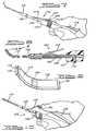
- FIG. 7 is a view of the instrument of the invention in the loaded condition;
- FIG. 8 is a cross sectional view of the instrument of Fig. 7;
- FIG. 9 is an enlarged perspective view taken within the circle "9" of Fig. 8;
- FIG. 10 is a view of the instrument in the unloaded condition;
- FIG. 11 is a cross sectional view of the instrument of Fig. 10;
- FIG. 12 in an elevational view of a tissue transfer pipette and syringe;
- FIG. 13 is a view of a piece of retinal tissue about to be discharged from the transfer tool of Fig. 12;
- FIG. 14 is a view of a surgical sponge effecting removal of transfer fluid after disposition of retinal tissue in a protective gel;
- FIG. 15 is a view of the retinal tissue enveloped in gel for protection; and
- FIG. 16 is a view of the retinal tissue being sized for induction into the nozzle of the instrument of the invention.
- The environment in which the present invention has particular utility is illustrated in Fig. 1 and 2 of the drawings. The front of the
eye 50 is covered by a transparent tissue, the cornea 52, surrounded by whiteconjunctive tissue 54. Thesclera 56 is hard fibrous tissue that covers the exterior of the eyeball. Thepupil 58 is the opening through which light passes to the back of the eye. Theiris 60 changes the size of thepupil 58 to adjust to the amount of light. Thetransparent lens 62 is located behind theiris 60 and is suspended by a net offibers 64. Thefibers 64 are attached to theciliary body 66 that extends to where theretina 68 begins. The part of theciliary body 66 adjacent to theretina 68 is calledpars plana 70. Thelens 62 focuses light rays onto theretina 68. The bulk of theeyeball 50 behind thelens 62 is formed by the vitreous chamber 72, which is filled with a colorless, gelatin like substance. - The
retina 68 covers most of the wall of the vitreous chamber 72 and comprises transparent layers that extend forwardly to the pars plana 70 and which processes light images projected from the cornea 52 and thelens 62. - The rear of the
retina 68 containsphotoreceptors 74, which transform light into electrical impulses. The electrical impulses are carried by nerves in theretina 68 to the optic nerve 76, which, in turn leads to the brain. A monolayer of cells termed the retinal pigment epithelium (RPE) 77 resides behind theretina 68. Thechoroid 78 is a layer of blood vessels behind the RPE 77, that supplies oxygen and nutrients essential to the function of theeye 50. The RPE 77 transports these nutrients to theretina 68 and maintains a barrier betweenchoroid 78 andretina 68. - The region between the
retina 68 and the RPE 77 is called the subretinal space 80 (Fig 4-6). Normally, there is no "space". However, theretina 68 detaches very easily from the RPE 77 and it is in this "space" that the surgeon transplants the new piece of retinal tissue to replace damagedphotoreceptors 74 and/or RPE 77. - The
fovea 82 is a small depression in the center of theretina 68 that is essential for sharp (focussed) vision as well as color vision. The small area surrounding thefovea 82 is known as the macula 84 and is responsible for central vision. The point at which the optic nerve 76 leaves theretina 68 on its way to the brain is calledoptic disc 86. - In accordance with the present invention, surgical correction of retinal diseases in the subretinal "space" 80 between the
retina 68 and the RPE 77 is facilitated by anovel implantation instrument 100. - As seen in Fig. 7 through 11, the
instrument 100 comprises ahandpiece 102, atubular sleeve support 104, amandrel 106 disposed internally of thesleeve support 104, asleeve 108 slidably journaled on thesleeve support 104, and anozzle 110 mounted on thesleeve 108. A nozzle control linkage comprises a toggle mechanism, which toggle mechanism comprises arigid link 114 and aspring link 115 and controls advancement and retraction of thesleeve 108 andnozzle 110 relative to themandrel 106. Thehandpiece 102,sleeve support 104,mandrel 106,sleeve 108 and togglelinks - The
mandrel 106 comprises an elongated flat and narrow strip of steel that is fixed in thehandpiece 102 by ascrew 116 so as to be longitudinally adjustable relative thereto. Extension or retraction of themandrel 106 relative to thehousing 102 regulates its longitudinal position relative to the length of the plastic nozzle in the retracted position (Fig. 10). - The fit between the
plastic nozzle 110 and themandrel 106 must permit relative movement, but induce a suction in atip portion 118 of thenozzle 110 when thenozzle 110 is advanced over themandrel 106 thereby to induct a rectangular piece ofretinal tissue 120. Alternatively, relatively hard implants can be inserted manually into thetip 118 of thenozzle 110. - The
nozzle 110 is molded of elastic plastic, for example fluorinated ethylene propylene, so as to have a curvature at thetip 118 thereof in order to slide under theretina 68 into the subretinal "space" 80. Because of its elasticity, thecurved nozzle tip 118, when retracted, will straighten out over themandrel 106 so as to deposit implant tissue at the target area behind theretina 68. It is to be noted that the tip of thenozzle 118 has smooth edges and, to facilitate uptake of theretinal tissue 120, may be provided with asmall lip 119 to aid in induction of theretinal tissue 120. - Advancement and retraction of the
sleeve 108 andnozzle 110 is controlled by therigid toggle link 114 andspring element 115 on thehandpiece 102. When thespring element 115 of the toggle mechanism is pressed toward thehandpiece 102, thesleeve 108 and thenozzle 110 are driven forwardly, relative to themandrel 106, by therigid toggle link 114 resulting in a partial vacuum internally of thetip portion 118 of thenozzle 110 that draws theretinal tissue 120 thereinto. When pressure on thespring element 115 of the toggle mechanism is released, thesleeve 108 and thenozzle 110 thereon is retracted over themandrel 106, exposing and placing theretinal tissue 120 at the desired location. - The
spring element 115 of the toggle mechanism can be locked in place by atoggle lock 130 that is engageable on apeg 132 on thespring element 115. A slight pressure on thespring element 115 releases thetoggle lock 130 allowing thenozzle 110 to retract over themandrel 106 under the bias of thespring element 115 thereby depositing theretinal tissue 120 in the target area vacated by thetip portion 118 of thenozzle 110 - In using the instrument of the invention, the surgeon first places an incision in the pars plana 70 of the
eye 50. A small incision is then made in, for example, the macular region 84 of theretina 68. If necessary, abnormal tissue is removed from the subretinal "space" 80 between theretina 68 and the RPE 77. Thenozzle 110 of theinstrument 100, with theretinal tissue 120 enclosed in thecurved nozzle tip 118 thereof, is inserted through the incision in the pars plana 70 and through the incision in theretina 68 until the tip of thenozzle 118 is orientated over the target area in the subretinal "space" 80. - Slight pressure on the
spring element 115 of theinstrument 100 then releases thetoggle lock 130 from thepin 132 allowing thespring element 115 andrigid link 114 of the toggle mechanism to effect retraction of thenozzle 110 and deposition of theretinal tissue 120. It is to be noted that thehandpiece 102 andmandrel 106 of theinstrument 100 are not required to move incident to deposition of theretinal tissue 120 allowing the surgeon to precisely position the tissue. - From the forgoing, it should be apparent that the instrument of the present invention is ideally suited for precisely placing implants into the eye. The surgeon has only to keep his hand still and exert a slight pressure on the
spring element 115 of theinstrument 100 to release thetoggle lock 130 conditioning theinstrument 100 itself to effect retraction of thenozzle 110 and placement of the implant on the target. - In practice of the disclosed application of the present invention, fetal human retinal tissue is harvested according to established procedures. Small pieces of retinal tissue are stored in a conventional hibernation medium on ice. As seen in Fig. 13 a piece of
retinal tissue 120 is transported in aconventional transport medium 134 in atransfer pipette 136. Preparations are made for the reception of theretinal tissue 120 by coating adish 200 with a thin layer of embeddinggel 202 which is then cooled or polymerized, depending on the type of gel, by incubation at 37° C or addition of a hardener, respectively. A 50-100 µL drop of embedding gel is placed onto thecoated dish 200, which forms alayer 204 for the reception of theretinal tissue 120. After theretinal tissue 120 is deposited, thetransfer medium 134 surrounding theretinal tissue 120 is removed by asurgical sponge 205 to prevent dilution of thelayer 204 of embedding gel. Theretinal tissue 120 is flattened as by capillary spreading of the drop of embedding gel forming thelayer 204. An additional small drop, for example 10-20 µL, of embedding gel is deposited over thelayer 204 to form anoverlying layer 206. The layers of embedding medium 202, 204 and 206 with theretinal tissue 120 embedded therein are then cooled or polymerized so as to be transformed into a gel that protects the embeddedretinal tissue 120. - After the embedding medium is properly cooled or polymerized, a conventional hibernation medium is added to the
dish 200 to prevent drying of theretinal tissue 120. Theretinal tissue 120 is thereafter stored on ice until use. - When ready for surgery, the
retinal tissue 120 is cut, as by amicroscissors 141, into arectangular section 140 for acceptance into thenozzle 110 of theimplantation instrument 100. Initially, a small piece ofgel 144 is placed adjacent themandrel 106 in thenozzle 110 of theimplantation instrument 100 to prevent theretinal tissue 120 from adhering to themandrel 106. The sized piece ofretinal tissue 120 is then inducted into thetip 118 of thenozzle 110. When the piece ofretinal tissue 120 is properly enclosed within thenozzle 110 of theinstrument 100, thelock pin 132 on thespring element 115 of the toggle mechanism is engaged in thetoggle lock 130. - After preparation of the eye for surgery, the
tip 118 of thenozzle 110 on theinstrument 100 is inserted into the target area of the eye behind the retinal flap. When thetip 118 of thenozzle 110 is orientated directly over the target, the surgeon applies a slight pressure on thespring element 115 of the toggle mechanism thereby releasing thelock pin 132 from thetoggle lock 130. Thenozzle 110 is retracted relative to themandrel 106 due to the bias of thespring element 115, depositing theretinal tissue 120 directly on the target. After deposit of theretinal tissue 120, the surgeon retracts theinstrument 100 from theeye 50. - It is to be noted that, in accordance with an important feature of the present invention, the surgeon's hand,
handpiece 102 andmandrel 106 are stationary while thenozzle 110 of theinstrument 100 retracts to effect placement of the implant.
Claims (4)
- An instrument (100) for implanting retinal tissue (120) into the human eye (50), the instrument comprising:an elongated mandrel (106) supported by a handpiece (102); anda tubular nozzle (110) telescoped over said mandrel (106);characterised in that the tubular nozzle (110) is slidable longitudinally relative to said mandrel (106), that the instrument further comprises a nozzle control linkage (114, 115) connected to said nozzle (110) and to said mandrel (106), movement of said control linkage relative to said mandrel effecting movement of said nozzle relative to said mandrel, and that said control linkage comprises a toggle mechanism (114, 115) having one end connected to said nozzle (110) and an opposite end connected to said handpiece (102).
- The instrument of claim 1, wherein the end of the tubular nozzle (110) contains an encapsulation of a fragment of retinal tissue (120) in a protective gel (202, 204, 206).
- The instrument of claim 1 or claim 2, including latching means (130) on said handpiece (102) engageable with said toggle mechanism (114, 115) to preclude relative movement therebetween.
- The instrument of claim 3, wherein the latching means (130) on said handpiece (102) is releasable to permit movement of said toggle mechanism (114, 115) so as to effect relative movement of said nozzle (110) relative to said mandrel (106).
Applications Claiming Priority (5)
| Application Number | Priority Date | Filing Date | Title |
|---|---|---|---|
| US3134796P | 1996-11-21 | 1996-11-21 | |
| US31347P | 1996-11-21 | ||
| US08/971,388US5941250A (en) | 1996-11-21 | 1997-11-17 | Retinal tissue implantation method |
| US971388 | 1997-11-17 | ||
| PCT/US1997/021339WO1998022029A1 (en) | 1996-11-21 | 1997-11-18 | Implantation instrument and method |
Publications (3)
| Publication Number | Publication Date |
|---|---|
| EP0967919A1 EP0967919A1 (en) | 2000-01-05 |
| EP0967919A4 EP0967919A4 (en) | 2000-01-12 |
| EP0967919B1true EP0967919B1 (en) | 2006-10-04 |
Family
ID=26707114
Family Applications (1)
| Application Number | Title | Priority Date | Filing Date |
|---|---|---|---|
| EP97947615AExpired - LifetimeEP0967919B1 (en) | 1996-11-21 | 1997-11-18 | Implantation instrument |
Country Status (7)
| Country | Link |
|---|---|
| US (1) | US5941250A (en) |
| EP (1) | EP0967919B1 (en) |
| JP (1) | JP2001509041A (en) |
| AU (1) | AU5265798A (en) |
| CA (1) | CA2271007C (en) |
| DE (1) | DE69736781T2 (en) |
| WO (1) | WO1998022029A1 (en) |
Cited By (3)
| Publication number | Priority date | Publication date | Assignee | Title |
|---|---|---|---|---|
| DE102011100371A1 (en) | 2011-05-03 | 2012-11-08 | Geuder Ag | Instrument for subretinal insertion of an implant |
| WO2014090244A1 (en) | 2012-12-13 | 2014-06-19 | Geuder Ag | Instrument for stimulating or irritating and/or abrasively treating and/or polishing a membrane or surface or inner surface in the human or animal eye |
| CN109475430A (en)* | 2016-08-10 | 2019-03-15 | 诺华股份有限公司 | Subretinal fluid drainage devices, systems and methods |
Families Citing this family (93)
| Publication number | Priority date | Publication date | Assignee | Title |
|---|---|---|---|---|
| US6514238B1 (en)* | 1989-08-14 | 2003-02-04 | Photogenesis, Inc. | Method for preparation and transplantation of volute grafts and surgical instrument therefor |
| SG49267A1 (en) | 1989-08-14 | 1998-05-18 | Photogenesis Inc | Surgical instrument and cell isolation and transplantation |
| US20060280774A1 (en)* | 1995-06-02 | 2006-12-14 | Allergan, Inc. | Compositions and methods for treating glaucoma |
| US5869079A (en)* | 1995-06-02 | 1999-02-09 | Oculex Pharmaceuticals, Inc. | Formulation for controlled release of drugs by combining hydrophilic and hydrophobic agents |
| DE19741487C2 (en)* | 1997-09-19 | 2000-08-31 | Univ Eberhard Karls | Device for access to the subretinal space of an eye |
| US6156042A (en)* | 1997-11-17 | 2000-12-05 | Aramant; Robert B. | Retinal tissue implantation instrument |
| US6358260B1 (en) | 1998-04-20 | 2002-03-19 | Med-Logics, Inc. | Automatic corneal shaper with two separate drive mechanisms |
| US6159218A (en)* | 1999-05-19 | 2000-12-12 | Aramant; Robert B. | Retinal tissue implantation tool |
| US6702832B2 (en) | 1999-07-08 | 2004-03-09 | Med Logics, Inc. | Medical device for cutting a cornea that has a vacuum ring with a slitted vacuum opening |
| US6699285B2 (en)* | 1999-09-24 | 2004-03-02 | Scieran Technologies, Inc. | Eye endoplant for the reattachment of a retina |
| US6416777B1 (en)* | 1999-10-21 | 2002-07-09 | Alcon Universal Ltd. | Ophthalmic drug delivery device |
| US6428508B1 (en) | 2000-02-01 | 2002-08-06 | Enlighten Technologies, Inc. | Pulsed vacuum cataract removal system |
| US7077848B1 (en)* | 2000-03-11 | 2006-07-18 | John Hopkins University | Sutureless occular surgical methods and instruments for use in such methods |
| US6389317B1 (en)* | 2000-03-31 | 2002-05-14 | Optobionics Corporation | Multi-phasic microphotodetector retinal implant with variable voltage and current capability |
| US20040039401A1 (en)* | 2000-03-31 | 2004-02-26 | Chow Alan Y. | Implant instrument |
| US7867186B2 (en) | 2002-04-08 | 2011-01-11 | Glaukos Corporation | Devices and methods for treatment of ocular disorders |
| US6638239B1 (en) | 2000-04-14 | 2003-10-28 | Glaukos Corporation | Apparatus and method for treating glaucoma |
| US6663644B1 (en) | 2000-06-02 | 2003-12-16 | Med-Logics, Inc. | Cutting blade assembly for a microkeratome |
| US6726918B1 (en) | 2000-07-05 | 2004-04-27 | Oculex Pharmaceuticals, Inc. | Methods for treating inflammation-mediated conditions of the eye |
| US7311700B2 (en) | 2000-11-29 | 2007-12-25 | Med-Logics, Inc. | LASIK laminar flow system |
| US6425905B1 (en) | 2000-11-29 | 2002-07-30 | Med-Logics, Inc. | Method and apparatus for facilitating removal of a corneal graft |
| US6699493B2 (en)* | 2000-11-29 | 2004-03-02 | Oculex Pharmaceuticals, Inc. | Method for reducing or preventing transplant rejection in the eye and intraocular implants for use therefor |
| AU2002258754B2 (en)* | 2001-04-07 | 2006-08-17 | Glaukos Corporation | Glaucoma stent and methods thereof for glaucoma treatment |
| US7037943B2 (en) | 2001-04-10 | 2006-05-02 | Optobionics Corporation | Retinal treatment method |
| US7331984B2 (en) | 2001-08-28 | 2008-02-19 | Glaukos Corporation | Glaucoma stent for treating glaucoma and methods of use |
| AU2002363315A1 (en)* | 2001-10-19 | 2003-05-19 | Innovative Retinal Products Llc | Macula cover and method |
| JP2005517468A (en)* | 2002-02-14 | 2005-06-16 | フォトジェネシス インコーポレイテッド | Subretinal transplant device and cannula used with the same |
| US9301875B2 (en) | 2002-04-08 | 2016-04-05 | Glaukos Corporation | Ocular disorder treatment implants with multiple opening |
| US8231637B2 (en)* | 2002-07-26 | 2012-07-31 | Second Sight Medical Products, Inc. | Surgical tool for electrode implantation |
| US7468065B2 (en) | 2002-09-18 | 2008-12-23 | Allergan, Inc. | Apparatus for delivery of ocular implants |
| PL223153B1 (en) | 2002-09-18 | 2016-10-31 | Allergan Inc | Methods and apparatus for delivery of ocular implants |
| US6899717B2 (en)* | 2002-09-18 | 2005-05-31 | Allergan, Inc. | Methods and apparatus for delivery of ocular implants |
| CA2498489C (en)* | 2002-09-29 | 2010-02-23 | Surmodics, Inc. | Method for subretinal administration of therapeutics including steroids;method for localizing pharmacodynamic action at the choroid and the retina; and related methods for treatment and/or prevention of retinal diseases |
| US20040117013A1 (en)* | 2002-12-12 | 2004-06-17 | Ira Schachar | Device and method for treating macular degeneration |
| US20050048099A1 (en) | 2003-01-09 | 2005-03-03 | Allergan, Inc. | Ocular implant made by a double extrusion process |
| US20040225250A1 (en) | 2003-05-05 | 2004-11-11 | Michael Yablonski | Internal shunt and method for treating glaucoma |
| US7291125B2 (en) | 2003-11-14 | 2007-11-06 | Transcend Medical, Inc. | Ocular pressure regulation |
| US20050244469A1 (en) | 2004-04-30 | 2005-11-03 | Allergan, Inc. | Extended therapeutic effect ocular implant treatments |
| US20060110428A1 (en) | 2004-07-02 | 2006-05-25 | Eugene Dejuan | Methods and devices for the treatment of ocular conditions |
| WO2006110487A1 (en)* | 2005-04-08 | 2006-10-19 | Surmodics, Inc. | Sustained release implants for subretinal delivery |
| WO2007087061A2 (en) | 2006-01-17 | 2007-08-02 | Transcend Medical, Inc. | Glaucoma treatment device |
| US20070178138A1 (en)* | 2006-02-01 | 2007-08-02 | Allergan, Inc. | Biodegradable non-opthalmic implants and related methods |
| US8668676B2 (en)* | 2006-06-19 | 2014-03-11 | Allergan, Inc. | Apparatus and methods for implanting particulate ocular implants |
| US20070298073A1 (en)* | 2006-06-23 | 2007-12-27 | Allergan, Inc. | Steroid-containing sustained release intraocular implants and related methods |
| US8802128B2 (en)* | 2006-06-23 | 2014-08-12 | Allergan, Inc. | Steroid-containing sustained release intraocular implants and related methods |
| US20080097335A1 (en)* | 2006-08-04 | 2008-04-24 | Allergan, Inc. | Ocular implant delivery assemblies |
| EP2088976B1 (en) | 2006-11-10 | 2019-07-03 | Glaukos Corporation | Uveoscleral shunt |
| JP4569971B2 (en)* | 2007-01-19 | 2010-10-27 | Hoya株式会社 | Equipment for transporting and administering therapeutic substances |
| EP2554661B2 (en) | 2007-04-18 | 2018-02-21 | Hadasit Medical Research Services & Development Limited | Stem cell-derived retinal pigment epithelial cells |
| JP5330401B2 (en) | 2007-11-08 | 2013-10-30 | アリメラ・サイエンシーズ,インコーポレーテッド | Implant device for the eye and kit comprising the device |
| USD592746S1 (en) | 2007-11-08 | 2009-05-19 | Alimera Sciences | Ocular implantation device |
| US8545554B2 (en)* | 2009-01-16 | 2013-10-01 | Allergan, Inc. | Intraocular injector |
| ES2920877T3 (en) | 2009-01-28 | 2022-08-11 | Alcon Inc | Ocular implant placement system |
| US8057483B2 (en)* | 2009-02-14 | 2011-11-15 | Ocular Transplantation Llc | Subretinal implantation instrument |
| US20100241060A1 (en)* | 2009-03-18 | 2010-09-23 | Roizman Keith | Surgical devices and methods |
| WO2012071476A2 (en) | 2010-11-24 | 2012-05-31 | David Haffner | Drug eluting ocular implant |
| GB201011313D0 (en)* | 2010-07-05 | 2010-08-18 | Ucl Business Plc | Implantation devices, methods and implants |
| US10285852B2 (en)* | 2010-12-02 | 2019-05-14 | Tel Hashomer Medical Research Infrastructure And Services Ltd., The Chaim Sheba Medical Center | Subretinal delivery of therapeutic compositions |
| US9655507B2 (en)* | 2011-11-02 | 2017-05-23 | Nidek Co., Ltd. | Corneal imaging device |
| CN104582767B (en) | 2012-02-23 | 2018-11-06 | 尤尼特拉克特注射器控股有限公司 | Retracting Needle Safety Syringes |
| US10272234B2 (en) | 2012-02-23 | 2019-04-30 | Unl Holdings Llc | Devices for targeted delivery of therapeutic implants |
| JP6109203B2 (en) | 2012-02-23 | 2017-04-12 | ユニトラクト シリンジ プロプライエタリイ リミテッドUnitract Syringe Pty Ltd | Instrument for targeted delivery of therapeutic implants |
| CA2868341C (en) | 2012-03-26 | 2021-01-12 | Glaukos Corporation | System and method for delivering multiple ocular implants |
| US10085633B2 (en) | 2012-04-19 | 2018-10-02 | Novartis Ag | Direct visualization system for glaucoma treatment |
| US9241832B2 (en) | 2012-04-24 | 2016-01-26 | Transcend Medical, Inc. | Delivery system for ocular implant |
| EP2895123B1 (en) | 2012-09-17 | 2017-06-07 | Novartis Ag | Expanding ocular implant devices |
| US9763829B2 (en) | 2012-11-14 | 2017-09-19 | Novartis Ag | Flow promoting ocular implant |
| AU2014212230B2 (en) | 2013-02-01 | 2019-07-04 | The United States Of America, As Represented By The Secretary, Department Of Health And Human Services | Method for generating retinal pigment epithelium (RPE) cells from induced pluripotent stem cells (iPSCs) |
| US9592151B2 (en) | 2013-03-15 | 2017-03-14 | Glaukos Corporation | Systems and methods for delivering an ocular implant to the suprachoroidal space within an eye |
| US9987163B2 (en) | 2013-04-16 | 2018-06-05 | Novartis Ag | Device for dispensing intraocular substances |
| KR101871084B1 (en) | 2013-12-11 | 2018-06-25 | 화이자 리미티드 | Method for producing retinal pigment epithelial cells |
| US10010447B2 (en)* | 2013-12-18 | 2018-07-03 | Novartis Ag | Systems and methods for subretinal delivery of therapeutic agents |
| EP3240890B1 (en) | 2014-12-30 | 2021-06-16 | Cell Cure Neurosciences Ltd. | Assessing retinal pigment epithelial cell populations |
| WO2016108239A1 (en) | 2014-12-30 | 2016-07-07 | Cell Cure Neurosciences Ltd. | Rpe cell populations and methods of generating same |
| WO2017017686A1 (en) | 2015-07-29 | 2017-02-02 | Hadasit Medical Research Services And Development Ltd. | Large scale production of retinal pigment epithelial cells |
| AU2016303631B2 (en) | 2015-08-05 | 2022-07-28 | Cell Cure Neurosciences Ltd. | Preparation of photoreceptors for the treatment of retinal diseases |
| CA2993912A1 (en) | 2015-08-05 | 2017-02-09 | Cell Cure Neurosciences Ltd. | Preparation of retinal pigment epithelium cells |
| HUE070900T2 (en) | 2015-10-26 | 2025-07-28 | Cell Cure Neurosciences Ltd | Preparation of retinal pigment epithelium cells |
| CN108366875A (en)* | 2015-12-14 | 2018-08-03 | 诺华股份有限公司 | Patch and relevant apparatus, system for sealing retinal hole and method |
| US20240415698A1 (en)* | 2017-01-16 | 2024-12-19 | Harry Michael Lambert | Opthalmological microsurgery instrumentation system and methods of use for pars planar vitrectomy |
| US12281328B2 (en) | 2017-02-08 | 2025-04-22 | Hadasit Medical Research Services And Development Ltd. | Photoreceptor cells for the treatment of retinal diseases |
| BR112019019190A2 (en) | 2017-03-16 | 2020-04-22 | Lineage Cell Therapeutics Inc | methods for treating diseases of the retina |
| US11116625B2 (en) | 2017-09-28 | 2021-09-14 | Glaukos Corporation | Apparatus and method for controlling placement of intraocular implants |
| CN110573117B (en) | 2017-10-06 | 2021-10-26 | 格劳科斯公司 | Systems and methods for delivering multiple ocular implants |
| USD846738S1 (en) | 2017-10-27 | 2019-04-23 | Glaukos Corporation | Implant delivery apparatus |
| SG11202005795TA (en) | 2017-12-29 | 2020-07-29 | Cell Cure Neurosciences Ltd | Retinal pigment epithelium cell compositions |
| CA3119041A1 (en) | 2018-11-19 | 2020-05-28 | The United States Of America, As Represented By The Secretary, Department Of Health And Human Services | Biodegradable tissue replacement implant and its use |
| CN114245733B (en) | 2019-06-14 | 2024-12-17 | 安特雷克公司 | Implantable bioscaffold and system for molding and preparation of biomaterials for use in the treatment of glaucoma |
| EP3754014A1 (en) | 2019-06-21 | 2020-12-23 | Centre d'Etude des Cellules Souches (CECS) | Automated method for preparing retinal pigment epithelium cells |
| JP7699150B2 (en) | 2020-05-20 | 2025-06-26 | イアンテック・インコーポレイテッド | System for forming and implanting a biological intraocular stent for increasing aqueous humor outflow and reducing intraocular pressure - Patents.com |
| AU2022280062A1 (en) | 2021-05-28 | 2023-11-30 | The United States Of America, As Represented By The Secretary, Department Of Health And Human Services | Methods to generate macular, central and peripheral retinal pigment epithelial cells |
| JP2024520423A (en) | 2021-05-28 | 2024-05-24 | ザ ユナイテッド ステイツ オブ アメリカ, アズ リプレゼンテッド バイ ザ セクレタリー, デパートメント オブ ヘルス アンド ヒューマン サービシーズ | Biodegradable tissue scaffolds with secondary matrices to accommodate weakly adherent cells - Patent Application 20070123333 |
| WO2022261320A1 (en) | 2021-06-09 | 2022-12-15 | Lineage Cell Therapeutics, Inc. | Methods and compositions for treating retinal diseases and conditions |
Citations (1)
| Publication number | Priority date | Publication date | Assignee | Title |
|---|---|---|---|---|
| US4597753A (en)* | 1983-04-21 | 1986-07-01 | Hundon Forge Limited | Implanting method and device |
Family Cites Families (7)
| Publication number | Priority date | Publication date | Assignee | Title |
|---|---|---|---|---|
| US4955889A (en)* | 1989-02-06 | 1990-09-11 | Allergan, Inc. | Apparatus for inserting a lens into an eye and method for using same |
| US5817075A (en)* | 1989-08-14 | 1998-10-06 | Photogenesis, Inc. | Method for preparation and transplantation of planar implants and surgical instrument therefor |
| CA2065230C (en)* | 1989-08-14 | 1999-07-20 | Stephen E. Hughes | Surgical instrument and cell isolation and transplantation |
| US5108421A (en)* | 1990-10-01 | 1992-04-28 | Quinton Instrument Company | Insertion assembly and method of inserting a vessel plug into the body of a patient |
| WO1994025569A1 (en)* | 1993-04-30 | 1994-11-10 | Photogenesis, Incorporated | Retinal pigment epithelium transplantation |
| CA2158443C (en)* | 1993-03-16 | 2003-11-25 | Stephen E. Hughes | Method for preparation and transplantation of volute grafts and surgical instrument therefor |
| US5468246A (en)* | 1993-07-02 | 1995-11-21 | Iovision, Inc. | Intraocular lens injector |
- 1997
- 1997-11-17USUS08/971,388patent/US5941250A/ennot_activeExpired - Lifetime
- 1997-11-18AUAU52657/98Apatent/AU5265798A/ennot_activeAbandoned
- 1997-11-18JPJP52299498Apatent/JP2001509041A/enactivePending
- 1997-11-18WOPCT/US1997/021339patent/WO1998022029A1/enactiveIP Right Grant
- 1997-11-18CACA002271007Apatent/CA2271007C/ennot_activeExpired - Fee Related
- 1997-11-18EPEP97947615Apatent/EP0967919B1/ennot_activeExpired - Lifetime
- 1997-11-18DEDE69736781Tpatent/DE69736781T2/ennot_activeExpired - Fee Related
Patent Citations (1)
| Publication number | Priority date | Publication date | Assignee | Title |
|---|---|---|---|---|
| US4597753A (en)* | 1983-04-21 | 1986-07-01 | Hundon Forge Limited | Implanting method and device |
Cited By (6)
| Publication number | Priority date | Publication date | Assignee | Title |
|---|---|---|---|---|
| DE102011100371A1 (en) | 2011-05-03 | 2012-11-08 | Geuder Ag | Instrument for subretinal insertion of an implant |
| WO2012150289A2 (en) | 2011-05-03 | 2012-11-08 | Rheinische Friedrich-Wilhelms-Universität | Instrument for the subretinal insertion of an implant |
| WO2014090244A1 (en) | 2012-12-13 | 2014-06-19 | Geuder Ag | Instrument for stimulating or irritating and/or abrasively treating and/or polishing a membrane or surface or inner surface in the human or animal eye |
| DE102012223076A1 (en) | 2012-12-13 | 2014-07-03 | Geuder Ag | Instrument for stimulation or irritation and / or for abrasive treatment and / or for polishing a membrane or surface or inner surface in the human or animal eye |
| US9980851B2 (en) | 2012-12-13 | 2018-05-29 | Geuder Ag | Instrument for stimulating or irritating and/or abrasively treating and/or polishing a membrane or surface or inner surface in the human or animal eye |
| CN109475430A (en)* | 2016-08-10 | 2019-03-15 | 诺华股份有限公司 | Subretinal fluid drainage devices, systems and methods |
Also Published As
| Publication number | Publication date |
|---|---|
| AU5265798A (en) | 1998-06-10 |
| US5941250A (en) | 1999-08-24 |
| WO1998022029A8 (en) | 1999-09-16 |
| EP0967919A1 (en) | 2000-01-05 |
| DE69736781T2 (en) | 2007-08-23 |
| DE69736781D1 (en) | 2006-11-16 |
| EP0967919A4 (en) | 2000-01-12 |
| CA2271007C (en) | 2006-06-13 |
| CA2271007A1 (en) | 1998-05-28 |
| WO1998022029A1 (en) | 1998-05-28 |
| JP2001509041A (en) | 2001-07-10 |
Similar Documents
| Publication | Publication Date | Title |
|---|---|---|
| EP0967919B1 (en) | Implantation instrument | |
| US6159218A (en) | Retinal tissue implantation tool | |
| CA2338984C (en) | Retinal tissue implantation instrument | |
| US8057483B2 (en) | Subretinal implantation instrument | |
| CN101715334B (en) | corneal implant | |
| US8540727B2 (en) | Insertion system for corneal implants | |
| CA2189040C (en) | Method for preparation and transplantation of planar implants and surgical instruments therefor | |
| CN102098993B (en) | Device for storing and injecting corneal grafts | |
| US6050999A (en) | Corneal implant introducer and method of use | |
| US4612012A (en) | Corneal implant | |
| US9549848B2 (en) | Corneal implant inserters and methods of use | |
| WO1996026759A9 (en) | Method for preparation and transplantation of planar implants and surgical instruments therefor |
Legal Events
| Date | Code | Title | Description |
|---|---|---|---|
| PUAI | Public reference made under article 153(3) epc to a published international application that has entered the european phase | Free format text:ORIGINAL CODE: 0009012 | |
| 17P | Request for examination filed | Effective date:19990616 | |
| AK | Designated contracting states | Kind code of ref document:A1 Designated state(s):CH DE GB LI SE | |
| A4 | Supplementary search report drawn up and despatched | Effective date:19991201 | |
| AK | Designated contracting states | Kind code of ref document:A4 Designated state(s):CH DE GB LI SE | |
| RAP1 | Party data changed (applicant data changed or rights of an application transferred) | Owner name:THE UNIVERSITY OF LOUISVILLE RESEARCH FOUNDATION, | |
| RIN1 | Information on inventor provided before grant (corrected) | Inventor name:SEILER, MAGDALENE J. Inventor name:ARAMANT, ROBERT B. | |
| 17Q | First examination report despatched | Effective date:20031113 | |
| GRAP | Despatch of communication of intention to grant a patent | Free format text:ORIGINAL CODE: EPIDOSNIGR1 | |
| RTI1 | Title (correction) | Free format text:IMPLANTATION INSTRUMENT | |
| GRAS | Grant fee paid | Free format text:ORIGINAL CODE: EPIDOSNIGR3 | |
| GRAA | (expected) grant | Free format text:ORIGINAL CODE: 0009210 | |
| AK | Designated contracting states | Kind code of ref document:B1 Designated state(s):CH DE GB LI SE | |
| PG25 | Lapsed in a contracting state [announced via postgrant information from national office to epo] | Ref country code:LI Free format text:LAPSE BECAUSE OF FAILURE TO SUBMIT A TRANSLATION OF THE DESCRIPTION OR TO PAY THE FEE WITHIN THE PRESCRIBED TIME-LIMIT Effective date:20061004 Ref country code:CH Free format text:LAPSE BECAUSE OF FAILURE TO SUBMIT A TRANSLATION OF THE DESCRIPTION OR TO PAY THE FEE WITHIN THE PRESCRIBED TIME-LIMIT Effective date:20061004 | |
| REG | Reference to a national code | Ref country code:GB Ref legal event code:FG4D | |
| REG | Reference to a national code | Ref country code:CH Ref legal event code:EP | |
| REF | Corresponds to: | Ref document number:69736781 Country of ref document:DE Date of ref document:20061116 Kind code of ref document:P | |
| PG25 | Lapsed in a contracting state [announced via postgrant information from national office to epo] | Ref country code:SE Free format text:LAPSE BECAUSE OF FAILURE TO SUBMIT A TRANSLATION OF THE DESCRIPTION OR TO PAY THE FEE WITHIN THE PRESCRIBED TIME-LIMIT Effective date:20070104 | |
| REG | Reference to a national code | Ref country code:CH Ref legal event code:PL | |
| PLBE | No opposition filed within time limit | Free format text:ORIGINAL CODE: 0009261 | |
| STAA | Information on the status of an ep patent application or granted ep patent | Free format text:STATUS: NO OPPOSITION FILED WITHIN TIME LIMIT | |
| 26N | No opposition filed | Effective date:20070705 | |
| PGFP | Annual fee paid to national office [announced via postgrant information from national office to epo] | Ref country code:DE Payment date:20081114 Year of fee payment:12 | |
| PGFP | Annual fee paid to national office [announced via postgrant information from national office to epo] | Ref country code:GB Payment date:20091118 Year of fee payment:13 | |
| PG25 | Lapsed in a contracting state [announced via postgrant information from national office to epo] | Ref country code:DE Free format text:LAPSE BECAUSE OF NON-PAYMENT OF DUE FEES Effective date:20100601 | |
| GBPC | Gb: european patent ceased through non-payment of renewal fee | Effective date:20101118 | |
| PG25 | Lapsed in a contracting state [announced via postgrant information from national office to epo] | Ref country code:GB Free format text:LAPSE BECAUSE OF NON-PAYMENT OF DUE FEES Effective date:20101118 |