EP0964268A1 - Method for increasing the angular coverage of a beam-forming radar, and radar therefor - Google Patents
Method for increasing the angular coverage of a beam-forming radar, and radar thereforDownload PDFInfo
- Publication number
- EP0964268A1 EP0964268A1EP99401314AEP99401314AEP0964268A1EP 0964268 A1EP0964268 A1EP 0964268A1EP 99401314 AEP99401314 AEP 99401314AEP 99401314 AEP99401314 AEP 99401314AEP 0964268 A1EP0964268 A1EP 0964268A1
- Authority
- EP
- European Patent Office
- Prior art keywords
- beams
- mesh
- radar
- interpolation
- memory
- Prior art date
- Legal status (The legal status is an assumption and is not a legal conclusion. Google has not performed a legal analysis and makes no representation as to the accuracy of the status listed.)
- Granted
Links
- 238000000034methodMethods0.000titleclaimsabstractdescription29
- 230000015572biosynthetic processEffects0.000claimsabstractdescription4
- 238000001514detection methodMethods0.000claimsdescription15
- 230000006870functionEffects0.000claimsdescription8
- 238000012545processingMethods0.000claimsdescription5
- 210000001525retinaAnatomy0.000claimsdescription3
- 238000012549trainingMethods0.000claimsdescription3
- 238000010586diagramMethods0.000description12
- 239000007787solidSubstances0.000description6
- 238000005070samplingMethods0.000description5
- 238000004519manufacturing processMethods0.000description2
- 238000012986modificationMethods0.000description2
- 230000004048modificationEffects0.000description2
- 230000005855radiationEffects0.000description2
- 230000035945sensitivityEffects0.000description2
- 238000011282treatmentMethods0.000description2
- 230000003044adaptive effectEffects0.000description1
- 230000003190augmentative effectEffects0.000description1
- 230000005540biological transmissionEffects0.000description1
- 238000011143downstream manufacturingMethods0.000description1
- 230000010354integrationEffects0.000description1
- 238000012544monitoring processMethods0.000description1
- 230000000135prohibitive effectEffects0.000description1
Images


Classifications
- G—PHYSICS
- G01—MEASURING; TESTING
- G01S—RADIO DIRECTION-FINDING; RADIO NAVIGATION; DETERMINING DISTANCE OR VELOCITY BY USE OF RADIO WAVES; LOCATING OR PRESENCE-DETECTING BY USE OF THE REFLECTION OR RERADIATION OF RADIO WAVES; ANALOGOUS ARRANGEMENTS USING OTHER WAVES
- G01S13/00—Systems using the reflection or reradiation of radio waves, e.g. radar systems; Analogous systems using reflection or reradiation of waves whose nature or wavelength is irrelevant or unspecified
- G01S13/02—Systems using reflection of radio waves, e.g. primary radar systems; Analogous systems
- G01S13/06—Systems determining position data of a target
- G01S13/42—Simultaneous measurement of distance and other co-ordinates
- G01S13/426—Scanning radar, e.g. 3D radar
- H—ELECTRICITY
- H01—ELECTRIC ELEMENTS
- H01Q—ANTENNAS, i.e. RADIO AERIALS
- H01Q3/00—Arrangements for changing or varying the orientation or the shape of the directional pattern of the waves radiated from an antenna or antenna system
- H01Q3/26—Arrangements for changing or varying the orientation or the shape of the directional pattern of the waves radiated from an antenna or antenna system varying the relative phase or relative amplitude of energisation between two or more active radiating elements; varying the distribution of energy across a radiating aperture
Definitions
- the present inventionrelates to a method of augmenting of the angular coverage of beam-forming radars, and of a radar implementing it.
- the circlesrepresent, in cross section, the angular extension of the beams formed, their diameters corresponding to the width of the diagrams radiation at their crossing points. This width is not necessarily that at -3dB; it can for example be determined at -2dB.
- the distance between the centers of the close circlesrepresents the step of the mesh. The choice of the configuration of the mesh and the degree of beam overlap is determined by the desired value of the probability of detection of a target.
- the number of beams needed to cover this standby volumecan be very high (several thousand for example), and moreover, the charge and / or the time of calculation, in particular to form the receiving beams, can be prohibitive.
- the subject of the present inventionis a method allowing increase the angular coverage of a beam-forming radar, which provides good detection performance (practically of the same order of magnitude as in the case of low coverage angular) without increasing the computing power and / or the time calculation for beam formation and downstream processing.
- the present inventionalso relates to a training radar.
- the method according to the inventionconsists, from a mesh of coarsely shaped beams, covering all the desired space, at interpolate the missing beams to obtain a step mesh sufficiently fine according to the probability of detection of targets desired.
- the method of the inventionconsists first of all in defining the number N and the angular positions of the beams necessary to reach from the outset, for the entire solid nail of the space to be monitored, the targeted detection performance objectives. These N angular positions constitute the global mesh Mo. Then, we form, by interpolation, to each new burst of a sequence, beams from the same angular positions than in the previous burst. So the treatments performed downstream (e.g. integration, apply on signals of the same angular origin.
- the positions of the actually formed bundlesare a subset (hereinafter called "Vibration") judiciously chosen from the global mesh (chosen in the way set out below).
- the additional beamsare calculated by interpolation from beams actually formed.
- the beams actually trainedoccupy other positions of the global network.
- the number of beams formed in each burstcan be constant, so too than the number of beams interpolated. However, according to a variant of the invention, these numbers can vary from one burst to the next or else after a certain number of bursts or depending on external events, for example following the appearance of a possible target, in order to increase the resolution in the area where this apparition occurred.
- the sequence successive bursts, which are used for radar processing, downstream interpolation,is a reason.
- the beams 1form a “triangular” mesh, the elements of which base (meshes) are substantially equilateral triangles (whose vertices are the centers of the three neighboring beams, two of the beams being located on a line, the third on the neighboring line).
- the interpolated beamsare alternately referenced 2 and 3, and their centers are located for example in the center of the respective triangles. It follows that the centers of the interpolated beams are aligned with the columns of the mesh 1, in order: 1,2,3,1, ...
- Interpolationis performed on complex numbers representative of the beam parameters (distance boxes, Doppler filter, burst %) and can be done in different ways known per se. For which is interpolation from the beams on the edges of the mesh, and not constituting a complete mesh, one can, for example, add fictitious beams to them to complete these meshes, and apply the same interpolation process as for complete meshes, or else modify the calculation of interpolation according to the number of beams of the meshes incomplete.
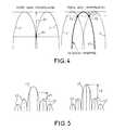
- the increase in performance of target detection for a given number of beams actually formedThe diagram on the left in Figure 4 relates to a speed camera without beam interpolation. We see that at the point P of crossing of beams actually formed, the loss of detection sensitivity S1 is important. On the other hand, thanks to the interpolation (interpolated beam FI on the right diagram of FIG. 4), the cross points P2 of the beam FI with neighboring beams F correspond to a loss of sensitivity S2 much less important than S1.
- the method of the inventionincreases the contrast between the main lobe of an antenna and its secondary lobes, with equal number of effectively formed bundles.
- the main lobe LP and the four side lobes LS of a radar antennaas well as the lines sampling.
- C1 and C2the minimal contrasts existing between the maximum measured amplitude of the LP lobe and the highest amplitude measured in one of the beams which do not belong to the neighborhood angular of LP, that is to say in the secondary lobes, and this, respectively in the case of the prior art (diagram on the left) and in the case of the process of the invention (diagram on the right).
- contrastsare determined between points lobe sampling. It can thus be seen that the interpolation of the process of the invention allows, thanks to a reduced sampling pitch, to increase the minimum contrast (C2> C1). We also improve the average contrast, i.e. the distance between the main lobe and the average level of the lobes secondary.
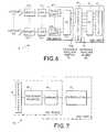
- FIG. 6shows the block diagram of the receiver 4 of a beamforming radar by calculation.
- This receiverhas a network antenna, possibly incomplete, with K sensors, referenced 5.1 to 5.K (which are generally all identical). Each of these sensors is followed by a receiving circuit (6.1 to 6.K respectively), a converter analog-digital (7.1 to 7.K respectively) and a suitable filter (8.1 to 8.K respectively). All filters 8.1 to 8.K. are connected to a single device 9 for forming beams by calculation.
- the elements described above , sensors to the device 9,are those addressed to each burst. AT the output of the device 9, the N / p beams of a partial mesh Mi are obtained (beams actually formed).
- the device 9is followed by an interpolation device 10 (putting using interpolation as described above), at the end of which obtains the N beams of the global mesh Mo, then of a post-integration circuit 11 and a detection circuit 12.
- Elements 10 to 12are relative to a "reason" (an angular sector of surveillance on standby).
- the radar transmission frequencycan vary between two gusts, so as to make the target "fluctuate” (to better characterize it).
- the process of the inventionadvantageously applies to adaptive training of beams by calculation, of which it retains the anti-jamming properties.
- FIG. 7shows the block diagram of the part reception 13 of an electronic scanning radar.
- a speed cameracan also include a network antenna. This is referenced 14 on the figure.
- Each elementary sensor of this antennais controlled analogically in phase, and possibly in amplitude, in order to participate to the formation of successive beams of different orientations, ensuring thus the required angular coverage.
- the network 14is followed by a circuit 15 for processing the received signals and a memory 16 (memorizing the signals received during each full scan sequence), and a interpolation device 17.
- Elements 14 to 16are addressed to each full scan burst, while the device 17 relates to a pattern (a antenna scanning area).
- Memory 16stores the signals complex for each burst, in order to allow the interpolation in 17.
- FIG. 8reception 18 of a focused structure antenna radar.
- This antennacomprises, for example, a sensor retina 19 placed at the focal point of a lens or reflector 20.
- the retina 19is followed by a combinatorial circuit 21 to form simultaneous beams, possibly anti-jamming, pointed in specific directions (what we call in English: "Stacked beams").
- the circuit 21is followed by a memory 22 storing complex signals for each burst.
- Memory 22is followed by a interpolation device 23, relating to a pattern.
- the interpolation devicesimplement the interpolation method of the invention, that is to say, in particular, that they perform interpolations between complex numbers, to ensure angular coverage desired, and this, from an effective gap mesh (not clearly greater than that required to ensure detection performance wanted) which it allows to fill the "holes" by inserting interpolated beams, thus forming a complete mesh, regular or not (in the latter case, we can locally have a higher density of beams, especially for more "careful" monitoring of an area of interest where we suspect for example the presence of a particular danger) and can evolve over time.
- the incomplete meshdoes not include necessarily always the same beams actually formed, and that we can alternately occupy these beams actually formed the places of the interpolated beams. So for the simplified example of the Figure 3, the meshes alternately correspond to the beams 1 actually formed, then to the interpolated beams of location index 2, then to the interpolated beams of location index 3, etc.
- the process of the inventioncan advantageously be applied to the location of interference sources, which requires a fine mesh of the potential angular domain of the threat.
Landscapes
- Engineering & Computer Science (AREA)
- Radar, Positioning & Navigation (AREA)
- Remote Sensing (AREA)
- Computer Networks & Wireless Communication (AREA)
- Physics & Mathematics (AREA)
- General Physics & Mathematics (AREA)
- Radar Systems Or Details Thereof (AREA)
Abstract
Translated fromFrench
Description
Translated fromFrenchLa présente invention se rapporte à un procédé d'augmentationde la couverture angulaire de radars à formation de faisceaux, et à un radarle mettant en oeuvre.The present invention relates to a method of augmentingof the angular coverage of beam-forming radars, and of a radarimplementing it.
On peut être amené à rechercher pour les radars, en particulier enfonction « veille », une couverture angulaire importante, afin de surveiller unespace étendu. Pour remplir cette fonction de veille volumétrique, les radarsà formation de faisceaux exploitent les signaux issus de faisceaux formésdans un angle solide donné pour des traitements comprenant: la post-intégrationde plusieurs rafales d'émission, la régulation de fausses alarmes,la détection de cibles, ... Pour pouvoir couvrir cet angle solide desurveillance, on l'échantillonne, c'est-à-dire que l'on forme suffisamment defaisceaux adjacents (couvrant chacun une petite partie de l'angle solide)pour que leur ensemble remplisse cet angle solide. C'est la méthode dite dumaillage. On a représenté en figures 1 et 2 les deux configurations les pluscourantes de maillage, respectivement dénommées « maillagerectangulaire» et maillage triangulaire. Sur ces figures, les cerclesreprésentent, en coupe transversale, l'extension angulaire des faisceauxformés, leurs diamètres correspondant à la largeur des diagrammes derayonnement en leurs points de croisement. Cette largeur n'est pasnécessairement celle à -3dB ; elle peut par exemple être déterminée à -2dB.La distance entre les centres des cercles proches représente le pas dumaillage. Le choix de la configuration du maillage et du degré derecouvrement des faisceaux est déterminé par la valeur souhaitée de laprobabilité de détection d'une cible.We may have to search for radars, in particular by"standby" function, significant angular coverage, in order to monitor aextended space. To perform this volumetric watch function, speed camerasbeam forming process signals from beams formedin a solid angle given for treatments including: post-integrationseveral emission bursts, the regulation of false alarms,target detection, ... To be able to cover this solid angle ofsurveillance, we sample it, i.e. we train enoughadjacent beams (each covering a small part of the solid angle)so that their whole fills this solid angle. This is the so-called method ofmesh. The two most common configurations are shown in FIGS. 1 and 2.current mesh, respectively called "meshrectangular "and triangular mesh. In these figures, the circlesrepresent, in cross section, the angular extension of the beamsformed, their diameters corresponding to the width of the diagramsradiation at their crossing points. This width is notnecessarily that at -3dB; it can for example be determined at -2dB.The distance between the centers of the close circles represents the step of themesh. The choice of the configuration of the mesh and the degree ofbeam overlap is determined by the desired value of theprobability of detection of a target.
Quelle que soit la configuration de maillage retenue, lorsque levolume de veille est grand par rapport à l'angle solide englobant l'ensembledes faisceaux formés (par exemple au moins cinq fois), le nombre defaisceaux nécessaires pour couvrir ce volume de veille peut être très élevé(plusieurs milliers par exemple), et par ailleurs, la charge et/ou le temps decalcul, en particulier pour former les faisceaux de réception, peuvent êtreprohibitifs. Il faut alors, pour couvrir tout le volume de veille, soit diminuer lenombre de faisceaux formés en augmentant le pas d'échantillonnage, soitdiviser le volume à couvrir en plusieurs secteurs traités successivement dans le temps. Dans ces deux cas, les performances du système de détectionsont fortement dégradées.Whatever the mesh configuration chosen, when thestandby volume is large compared to the solid angle encompassing the wholebeams formed (e.g. at least five times), the number ofbeams needed to cover this standby volume can be very high(several thousand for example), and moreover, the charge and / or the time ofcalculation, in particular to form the receiving beams, can beprohibitive. To cover the entire standby volume, you must either decrease thenumber of beams formed by increasing the sampling pitch, i.e.divide the volume to be covered into several sectors treated successively inthe weather. In both cases, the performance of the detection systemare severely degraded.
La présente invention a pour objet un procédé permettantd'augmenter la couverture angulaire d'un radar à formation de faisceaux, quipermette d'en obtenir de bonnes performances de détection (pratiquementdu même ordre de grandeur que dans le cas d'une faible couvertureangulaire) sans pour autant augmenter la puissance de calcul et/ou le tempsde calcul pour la formation des faisceaux et le traitement aval.The subject of the present invention is a method allowingincrease the angular coverage of a beam-forming radar, whichprovides good detection performance (practicallyof the same order of magnitude as in the case of low coverageangular) without increasing the computing power and / or the timecalculation for beam formation and downstream processing.
La présente invention a également pour objet un radar à formationde faisceaux à très grande couverture angulaire, en particulier en fonction deveille, dont le prix de revient ne soit pratiquement pas plus élevé que celuid'un modèle similaire à faible couverture angulaire, et qui puisse même êtreréalisé à partir d'un modèle existant, sans modifications de sa partiemécanique, et avec peu de modifications de sa partie électronique.The present invention also relates to a training radar.beams with very large angular coverage, in particular as a function ofstandby, the cost price of which is practically no higher than thata similar model with low angular coverage, which can even bemade from an existing model, without modification of its partmechanical, and with few modifications of its electronic part.
Le procédé conforme à l'invention consiste, à partir d'un maillagede faisceaux formés à pas grossier, couvrant tout l'espace désiré, àinterpoler les faisceaux manquants pour obtenir un maillage à passuffisamment fin en fonction de la probabilité de détection de ciblessouhaitée.The method according to the invention consists, from a meshof coarsely shaped beams, covering all the desired space, atinterpolate the missing beams to obtain a step meshsufficiently fine according to the probability of detection of targetsdesired.
La présente invention sera mieux comprise à la lecture de ladescription détaillée de plusieurs modes de mise en oeuvre, pris à titred'exemples non limitatifs et illustrés par le dessin annexé, sur lequel :
- les figures 1 et 2, déjà décrites ci-dessus, sont des vuesschématisées partielles de deux configurations courantes de maillage defaisceaux de radars,
- la figure 3 est un schéma simplifié permettant d'expliquer leprocédé de l'invention,
- les figures 4 et 5 sont des diagrammes de lobes de rayonnementmontrant les avantages de l'invention, et
- les figures 6 à 8 sont des blocs-diagrammes de différents typesde radars mettant en oeuvre l'invention.
- FIGS. 1 and 2, already described above, are partial schematic views of two current configurations of mesh of radar beams,
- FIG. 3 is a simplified diagram making it possible to explain the method of the invention,
- FIGS. 4 and 5 are diagrams of radiation lobes showing the advantages of the invention, and
- Figures 6 to 8 are block diagrams of different types of radars implementing the invention.
L'invention est décrite ci-dessous en référence à la fonction deveille d'un radar, mais il est bien entendu qu'elle n'est pas limitée à cetteseule application, et qu'elle peut aussi bien être mise en oeuvre pourd'autres fonctions, telle la poursuite de cibles, et ce, quel que soit le type de radar à formation de faisceaux: à formation de faisceaux par le calcul, àbalayage électronique, à structure focalisée,...The invention is described below with reference to the function ofradar watch, but it is understood that it is not limited to thissingle application, and that it can as well be implemented forother functions, such as target tracking, regardless of the type ofbeam forming radar: beam forming by calculation,electronic scanning, with focused structure, ...
Le procédé de l'invention consiste tout d'abord à définir le nombreN et les positions angulaires des faisceaux nécessaires pour atteindred'emblée, pour la totalité de l'ongle solide de l'espace à surveiller, lesobjectifs de performance de détection visés. Ces N positions angulairesconstituent le maillage global Mo. Ensuite, on forme, par interpolation, àchaque nouvelle rafale d'un séquencement, des faisceaux issus des mêmespositions angulaires qu'à la rafale précédente. Ainsi, les traitementseffectués en aval (par exemple une intégration, s'appliquent sur des signauxde même provenance angulaire.The method of the invention consists first of all in defining the numberN and the angular positions of the beams necessary to reachfrom the outset, for the entire solid nail of the space to be monitored, thetargeted detection performance objectives. These N angular positionsconstitute the global mesh Mo. Then, we form, by interpolation, toeach new burst of a sequence, beams from the sameangular positions than in the previous burst. So the treatmentsperformed downstream (e.g. integration, apply on signalsof the same angular origin.
A cet effet, les signaux traités à chaque rafale, et pour chacunedes N positions d'échantillonnage du maillage global Mo sont soit issus desfaisceaux effectivement formés dans les N/p positions angulaires demaillages « partiels » Mi (avec = 1...p), soit interpolés à partir des signauxdes positions voisines (effectivement formées).For this purpose, the signals processed at each burst, and for eachN sampling positions of the global mesh Mo are either derived frombeams actually formed in the N / p angular positions of“partial” meshes Mi (with = 1 ... p), ie interpolated from the signalsneighboring positions (actually formed).
Ainsi, lors de la production d'une rafale, les positions desfaisceaux effectivement formés sont un sous-ensemble (appelé par la suite« vibration ») judicieusement choisi du maillage global (choisi de la manièreexposée ci-dessous). Les faisceaux complémentaires (nécessaires pourdéfinir la totalité du maillage global) sont calculés par interpolation à partirdes faisceaux effectivement formés.Thus, during the production of a burst, the positions of theactually formed bundles are a subset (hereinafter called"Vibration") judiciously chosen from the global mesh (chosen in the wayset out below). The additional beams (necessary fordefine the entire global mesh) are calculated by interpolation frombeams actually formed.
Lors de la production des rafales suivantes, les faisceauxeffectivement formés occupent d'autres positions du maillage global. Lenombre de faisceaux formés à chaque rafale peut être constant, de mêmeque le nombre de faisceaux interpolés. Toutefois, selon une variante del'invention, ces nombres peuvent varier d'une rafale à la suivante ou bienaprès un certain nombre de rafales ou en fonction d'événements extérieurs,par exemple par suite d'apparition d'une éventuelle cible, afin d'augmenter larésolution dans la zone où s'est produite cette apparition. L'enchaínementdes rafales successives, qui sont utilisées pour les traitements radar, en avalde l'interpolation, constitue un motif. On peut avantageusement associer leprocédé de l'invention à un traitement de post-intégration sur plusieursrafales. Bien entendu, au lieu d'augmenter la couverture angulaire, ou en plus de cette augmentation, on peut améliorer la finesse du maillageexistant, afin d'améliorer les performances de détection du radar.During the production of the following bursts, the beamsactually trained occupy other positions of the global network. Thenumber of beams formed in each burst can be constant, so toothan the number of beams interpolated. However, according to a variant ofthe invention, these numbers can vary from one burst to the next or elseafter a certain number of bursts or depending on external events,for example following the appearance of a possible target, in order to increase theresolution in the area where this apparition occurred. The sequencesuccessive bursts, which are used for radar processing, downstreaminterpolation, is a reason. We can advantageously associate themethod of the invention to post-integration processing on severalgusts. Of course, instead of increasing the angular coverage, or bymore of this increase, we can improve the fineness of the meshto improve radar detection performance.
Le procédé de l'invention sera maintenant explicité en référence àla figure 3. Ce procédé consiste, pour chacune des p « vibrations» à neformer effectivement que N/p faisceaux du maillage global, puis à interpolerchacun des (N- N/p) faisceaux manquants à l'aide des faisceaux voisins. Ona illustré en figure 3 le cas où p = 3, avec un maillage triangulaire. On aattribué la référence numérique 1 aux faisceaux de la « vibration» 1, quicorrespond aux faisceaux effectivement formés. Les références numériques2 et 3 correspondent aux « vibrations » dont les faisceaux sont interpolés.Bien entendu, p peut avoir d'autres valeurs. Comme représenté sur la figure3, les faisceaux 1 forment un maillage « triangulaire », dont les éléments debase (mailles) sont des triangles sensiblement équilatéraux (dont lessommets sont les centres des trois faisceaux voisins, deux des faisceauxétant situés sur une ligne, le troisième sur la ligne voisine). En considérantles triangles successifs déterminés entre les deux mêmes lignes, lesfaisceaux interpolés sont alternativement référencés 2 et 3, et leurs centressont situés par exemple au centre des triangles respectifs. Il en résulte queles centres des faisceaux interpolés sont alignés sur les colonnes dumaillage 1, dans l'ordre : 1,2,3,1, ...The process of the invention will now be explained with reference toFIG. 3. This process consists, for each of the p "vibrations" in notactually form that N / p beams of the global mesh, then to interpolateeach of the (N- N / p) beams missing using the neighboring beams. Weillustrated in figure 3 the case where p = 3, with a triangular mesh. We haveassigned the
L'interpolation est opérée sur les nombres complexesreprésentatifs des paramètres des faisceaux (cases distance, filtre Doppler,rafale...) et peut se faire de différentes façons connues en soi. Pour ce quiest de l'interpolation à partir des faisceaux se trouvant sur les bords dumaillage, et ne constituant pas une maille complète, on peut, par exemple,leur adjoindre des faisceaux fictifs pour compléter ces mailles, et appliquer lemême procédé d'interpolation qu'aux mailles complètes, ou bien modifier lecalcul d'interpolation en fonction du nombre de faisceaux des maillesincomplètes.Interpolation is performed on complex numbersrepresentative of the beam parameters (distance boxes, Doppler filter,burst ...) and can be done in different ways known per se. For whichis interpolation from the beams on the edges of themesh, and not constituting a complete mesh, one can, for example,add fictitious beams to them to complete these meshes, and apply thesame interpolation process as for complete meshes, or else modify thecalculation of interpolation according to the number of beams of the meshesincomplete.
On va exposer, en référence aux figures 4 et 5 les avantages duprocédé de l'invention en termes de charge de calcul de la fonction veille etde performances de détection de cible.We will explain, with reference to Figures 4 and 5 the advantages ofmethod of the invention in terms of computational load of the standby function andtarget detection performance.
On prend en exemple un radar à formation de faisceaux par lecalcul. Ce radar dispose de K capteurs (correspondant à K faisceauxeffectivement formés), alors que N faisceaux (N>>K) sont nécessaires pour assurer la couverture angulaire recherchée, avec des performances dedétection de cible déterminées. Le procédé de l'art antérieur nécessiterait4.K.N opérations à chaque rafale. Par contre, le procédé de l'invention nenécessite que 4.K. N/p opérations pour former les faisceaux et 4.p.Nopérations d'interpolation, soit au total : 4.N (K/p + p) opérations. Le gain encharge de calcul est donc égal à (K/p + p)/K. Si, par exemple, K = 16 etp = 3, le gain en charge de calcul est presque égal à 2.Take for example a beam-forming radar by thecalculation. This radar has K sensors (corresponding to K beamsactually formed), while N beams (N >> K) are necessary forensure the desired angular coverage, with performances oftarget detection determined. The prior art method would require4.K.N operations at each burst. On the other hand, the method of the invention does notrequires that 4.K. N / p operations to form the beams and 4.p.Ninterpolation operations, ie in total: 4.N (K / p + p) operations. The gain incomputational load is therefore equal to (K / p + p) / K. If, for example, K = 16 andp = 3, the gain in calculation load is almost equal to 2.
On a illustré en figure 4 l'augmentation des performances dedétection de cible pour un nombre donné de faisceaux effectivement formés.Le diagramme de gauche de la figure 4 se rapporte à un radar sansinterpolation de faisceaux. On voit qu'au point P de croisement desfaisceaux effectivement formés, la perte de sensibilité de détection S1 estimportante. Par contre, grâce à l'interpolation (faisceau interpolé FI sur lediagramme de droite de la figure 4), les points de croisement P2 du faisceauFI avec les faisceaux voisins F correspondent à une perte de sensibilité S2beaucoup moins importante que S1.The increase in performance oftarget detection for a given number of beams actually formed.The diagram on the left in Figure 4 relates to a speed camera withoutbeam interpolation. We see that at the point P of crossing ofbeams actually formed, the loss of detection sensitivity S1 isimportant. On the other hand, thanks to the interpolation (interpolated beam FI on theright diagram of FIG. 4), the cross points P2 of the beamFI with neighboring beams F correspond to a loss of sensitivity S2much less important than S1.
En outre, comme illustré en figure 5, le procédé de l'inventionpermet d'augmenter le contraste entre le lobe principal d'une antenne et seslobes secondaires, à nombre égal de faisceaux effectivement formés. Surles deux diagrammes de cette figure, on a représenté le lobe principal LP etles quatre lobes secondaires LS d'une antenne radar, ainsi que les raiesd'échantillonnage. On a noté C1 et C2 les contrastes minimaux existantentre l'amplitude maximale mesurée du lobe LP et l'amplitude la plus élevéemesurée dans un des faisceaux qui n'appartiennent pas au voisinageangulaire de LP, c'est-à-dire dans les lobes secondaires, et ce,respectivement dans le cas de l'art antérieur (diagramme de gauche) et dansle cas du procédé de l'invention (diagramme de droite).In addition, as illustrated in FIG. 5, the method of the inventionincreases the contrast between the main lobe of an antenna and itssecondary lobes, with equal number of effectively formed bundles. Surethe two diagrams of this figure, we represented the main lobe LP andthe four side lobes LS of a radar antenna, as well as the linessampling. We noted C1 and C2 the minimal contrasts existingbetween the maximum measured amplitude of the LP lobe and the highest amplitudemeasured in one of the beams which do not belong to the neighborhoodangular of LP, that is to say in the secondary lobes, and this,respectively in the case of the prior art (diagram on the left) and inthe case of the process of the invention (diagram on the right).
Ces contrastes sont déterminés entre des pointsd'échantillonnage des lobes. On constate ainsi que l'interpolation du procédéde l'invention permet, grâce à un pas d'échantillonnage réduit, d'augmenterle contraste minimum (C2 > C1). On améliore également le contraste moyen,c'est-à-dire l'écart entre le lobe principal et le niveau moyen des lobessecondaires.These contrasts are determined between pointslobe sampling. It can thus be seen that the interpolation of the processof the invention allows, thanks to a reduced sampling pitch, to increasethe minimum contrast (C2> C1). We also improve the average contrast,i.e. the distance between the main lobe and the average level of the lobessecondary.
On a représenté en figure 6 le bloc-diagramme du récepteur 4d'un radar à formation de faisceaux par le calcul. Ce récepteur comporte une antenne-réseau, éventuellement lacunaire, à K capteurs, référencés 5.1 à5.K (qui sont généralement tous identiques). Chacun de ces capteurs estsuivi d'un circuit de réception (6.1 à 6.K respectivement), d'un convertisseuranalogique-numérique (7.1 à 7.K respectivement) et d'un filtre adapté (8.1 à8.K respectivement). Tous les filtres 8.1 à 8.K. sont reliés à un uniquedispositif 9 de formation de faisceaux par le calcul. Les éléments décrits ci-dessus, des capteurs au dispositif 9, sont ceux adressés à chaque rafale. Ala sortie du dispositif 9, on obtient les N/p faisceaux d'un maillage partiel Mi(faisceaux effectivement formés).FIG. 6 shows the block diagram of the
Le dispositif 9 est suivi d'un dispositif 10 d'interpolation (mettanten oeuvre l'interpolation telle que décrite ci-dessus), à la sortie duquel onobtient les N faisceaux du maillage global Mo, puis d'un circuit 11 de post-intégrationet d'un circuit 12 de détection. Les éléments 10 à 12 sont relatifsà un « motif » (un secteur angulaire de surveillance en veille). De façonavantageuse, la fréquence d'émission du radar peut varier entre deuxrafales, de façon à faire « fluctuer » la cible (pour mieux la caractériser). Leprocédé de l'invention s'applique avantageusement à la formation adaptativede faisceaux par le calcul, dont il conserve les propriétés d'antibrouillage.The device 9 is followed by an interpolation device 10 (puttingusing interpolation as described above), at the end of whichobtains the N beams of the global mesh Mo, then of a
On a représenté en figure 7 le bloc-diagramme de la partieréception 13 d'un radar à balayage électronique. Un tel radar peutégalement comporter une antenne-réseau. Celle-ci est référencée 14 sur lafigure. Chaque capteur élémentaire de cette antenne est commandéanalogiquement en phase, et éventuellement en amplitude, afin de participerà la formation de faisceaux successifs d'orientations différentes, assurantainsi la couverture angulaire requise. Le réseau 14 est suivi d'un circuit 15de traitement des signaux reçus et d'une mémoire 16 (mémorisant lessignaux reçus lors de chaque séquence de balayage complet), et d'undispositif d'interpolation 17. Les éléments 14 à 16 sont adressés à chaquerafale de balayage complet, alors que le dispositif 17 est relatif à un motif (unsecteur de balayage de l'antenne). La mémoire 16 stocke les signauxcomplexes pour chaque rafale, afin d'en permettre l'interpolation en 17.FIG. 7 shows the block diagram of the
On a représenté en figure 8 le bloc-diagramme de la partieréception 18 d'un radar à antenne à structure focalisée. Cette antennecomporte, par exemple, une rétine de capteurs 19 placée au foyer d'unelentille ou d'un réflecteur 20. La rétine 19 est suivie d'un circuit combinatoire 21 pour former des faisceaux simultanés, éventuellement antibrouillés,pointés dans des directions déterminées (ce que l'on appelle en anglais :« stacked beams »). Le circuit 21 est suivi d'une mémoire 22 stockant dessignaux complexes pour chaque rafale. La mémoire 22 est suivie d'undispositif d'interpolation 23, relatif à un motif.The block diagram of the part is shown in FIG. 8.
Dans les trois modes de réalisation décrits ci-dessus, lesdispositifs d'interpolation mettent en oeuvre le procédé d'interpolation del'invention, c'est-à-dire, en particulier, qu'ils effectuent des interpolationsentre des nombres complexes, afin d'assurer la couverture angulairesouhaitée, et ce, à partir d'un maillage lacunaire effectif (à pas nettementsupérieur à celui nécessaire pour assurer les performances de détectionrecherchées) dont il permet de combler les « trous» en y insérant desfaisceaux interpolés, formant ainsi un maillage complet, régulier ou non(dans ce dernier cas, on peut avoir localement une plus grande densité defaisceaux, en particulier pour surveiller de façon plus « attentive » une zoned'intérêt où l'on soupçonne par exemple la présence d'un danger particulier)et pouvant évoluer dans le temps.In the three embodiments described above, theinterpolation devices implement the interpolation method ofthe invention, that is to say, in particular, that they perform interpolationsbetween complex numbers, to ensure angular coveragedesired, and this, from an effective gap mesh (not clearlygreater than that required to ensure detection performancewanted) which it allows to fill the "holes" by insertinginterpolated beams, thus forming a complete mesh, regular or not(in the latter case, we can locally have a higher density ofbeams, especially for more "careful" monitoring of an areaof interest where we suspect for example the presence of a particular danger)and can evolve over time.
Il est à noter que le maillage lacunaire ne comporte pasnécessairement toujours les mêmes faisceaux effectivement formés, et quel'on peut faire occuper alternativement à ces faisceaux effectivement formésles places des faisceaux interpolés. Ainsi, pour l'exemple simplifié de lafigure 3, les maillages correspondent alternativement aux faisceaux 1effectivement formés, puis aux faisceaux interpolés d'indice de repérage 2,puis aux faisceaux interpolés d'indice de repérage 3, etc...It should be noted that the incomplete mesh does not includenecessarily always the same beams actually formed, and thatwe can alternately occupy these beams actually formedthe places of the interpolated beams. So for the simplified example of theFigure 3, the meshes alternately correspond to the
Le procédé de l'invention peut s'appliquer avantageusement à lalocalisation de sources de brouillage, qui nécessite un maillage fin dudomaine angulaire potentiel de la menace.The process of the invention can advantageously be applied to thelocation of interference sources, which requires a fine mesh of thepotential angular domain of the threat.
Claims (10)
Translated fromFrenchApplications Claiming Priority (2)
| Application Number | Priority Date | Filing Date | Title |
|---|---|---|---|
| FR9807440AFR2779831B1 (en) | 1998-06-12 | 1998-06-12 | METHOD FOR INCREASING THE ANGULAR COVERAGE OF BEAM-FORMING RADARS, AND RADAR USING THE SAME |
| FR9807440 | 1998-06-12 |
Publications (2)
| Publication Number | Publication Date |
|---|---|
| EP0964268A1true EP0964268A1 (en) | 1999-12-15 |
| EP0964268B1 EP0964268B1 (en) | 2008-04-09 |
Family
ID=9527330
Family Applications (1)
| Application Number | Title | Priority Date | Filing Date |
|---|---|---|---|
| EP19990401314Expired - LifetimeEP0964268B1 (en) | 1998-06-12 | 1999-06-01 | Method for increasing the angular coverage of a beam-forming radar, and radar therefor |
Country Status (3)
| Country | Link |
|---|---|
| EP (1) | EP0964268B1 (en) |
| DE (1) | DE69938475T2 (en) |
| FR (1) | FR2779831B1 (en) |
Cited By (1)
| Publication number | Priority date | Publication date | Assignee | Title |
|---|---|---|---|---|
| FR2951586A1 (en)* | 2009-10-20 | 2011-04-22 | Thales Sa | ANTENNA ARCHITECTURE INVOLVING BEAM SYNTHESIS WITH VARIABLE PASTE SAMPLE |
Families Citing this family (12)
| Publication number | Priority date | Publication date | Assignee | Title |
|---|---|---|---|---|
| US7612716B2 (en) | 1999-03-05 | 2009-11-03 | Era Systems Corporation | Correlation of flight track data with other data sources |
| US8446321B2 (en) | 1999-03-05 | 2013-05-21 | Omnipol A.S. | Deployable intelligence and tracking system for homeland security and search and rescue |
| US7739167B2 (en) | 1999-03-05 | 2010-06-15 | Era Systems Corporation | Automated management of airport revenues |
| US7889133B2 (en) | 1999-03-05 | 2011-02-15 | Itt Manufacturing Enterprises, Inc. | Multilateration enhancements for noise and operations management |
| US7570214B2 (en) | 1999-03-05 | 2009-08-04 | Era Systems, Inc. | Method and apparatus for ADS-B validation, active and passive multilateration, and elliptical surviellance |
| US8203486B1 (en) | 1999-03-05 | 2012-06-19 | Omnipol A.S. | Transmitter independent techniques to extend the performance of passive coherent location |
| US7667647B2 (en) | 1999-03-05 | 2010-02-23 | Era Systems Corporation | Extension of aircraft tracking and positive identification from movement areas into non-movement areas |
| US7782256B2 (en) | 1999-03-05 | 2010-08-24 | Era Systems Corporation | Enhanced passive coherent location techniques to track and identify UAVs, UCAVs, MAVs, and other objects |
| US7908077B2 (en) | 2003-06-10 | 2011-03-15 | Itt Manufacturing Enterprises, Inc. | Land use compatibility planning software |
| US7777675B2 (en) | 1999-03-05 | 2010-08-17 | Era Systems Corporation | Deployable passive broadband aircraft tracking |
| US7965227B2 (en) | 2006-05-08 | 2011-06-21 | Era Systems, Inc. | Aircraft tracking using low cost tagging as a discriminator |
| US11483751B2 (en)* | 2017-08-18 | 2022-10-25 | Telefonaktiebolaget Lm Ericsson (Publ) | Method for evaluating cell quality of cells using beamforming |
Citations (2)
| Publication number | Priority date | Publication date | Assignee | Title |
|---|---|---|---|---|
| US4654665A (en)* | 1983-07-21 | 1987-03-31 | Nec Corporation | Radar system |
| US5537367A (en)* | 1994-10-20 | 1996-07-16 | Lockwood; Geoffrey R. | Sparse array structures |
- 1998
- 1998-06-12FRFR9807440Apatent/FR2779831B1/ennot_activeExpired - Fee Related
- 1999
- 1999-06-01DEDE1999638475patent/DE69938475T2/ennot_activeExpired - Lifetime
- 1999-06-01EPEP19990401314patent/EP0964268B1/ennot_activeExpired - Lifetime
Patent Citations (2)
| Publication number | Priority date | Publication date | Assignee | Title |
|---|---|---|---|---|
| US4654665A (en)* | 1983-07-21 | 1987-03-31 | Nec Corporation | Radar system |
| US5537367A (en)* | 1994-10-20 | 1996-07-16 | Lockwood; Geoffrey R. | Sparse array structures |
Cited By (2)
| Publication number | Priority date | Publication date | Assignee | Title |
|---|---|---|---|---|
| FR2951586A1 (en)* | 2009-10-20 | 2011-04-22 | Thales Sa | ANTENNA ARCHITECTURE INVOLVING BEAM SYNTHESIS WITH VARIABLE PASTE SAMPLE |
| EP2320522A1 (en)* | 2009-10-20 | 2011-05-11 | Thales | Antenna architecture implementing a synthesis of beams with samplers at variable pitch |
Also Published As
| Publication number | Publication date |
|---|---|
| DE69938475T2 (en) | 2009-07-09 |
| FR2779831A1 (en) | 1999-12-17 |
| FR2779831B1 (en) | 2000-09-01 |
| DE69938475D1 (en) | 2008-05-21 |
| EP0964268B1 (en) | 2008-04-09 |
Similar Documents
| Publication | Publication Date | Title |
|---|---|---|
| EP0964268A1 (en) | Method for increasing the angular coverage of a beam-forming radar, and radar therefor | |
| CA2134055A1 (en) | Radiating element array antenna | |
| FR2712989A1 (en) | Direction finding system to locate direction of HF radio transmission | |
| EP0322005A1 (en) | Radioelectrical sensor for creating a radioelectrical map of a site | |
| EP0891005A1 (en) | Array antenna with anti-jamming | |
| EP0733408B1 (en) | Ultrasonic sensor and detection method using such a sensor | |
| FR3050538A1 (en) | METHOD FOR OPTIMIZING THE DETECTION OF MARINE AND RADAR TARGETS USING SUCH A METHOD | |
| EP0002642B1 (en) | High resolution antenna system | |
| EP0752597B1 (en) | Polarimetric detection processing circuit for a radar receiver | |
| FR2694662A1 (en) | High resolution beam forming apparatus for target detection systems | |
| EP0106418B1 (en) | Apparatus for examining media by ultrasonic echography | |
| FR2465233A1 (en) | APPARATUS FOR DETERMINING AN ULTRASONIC RADAR DEPOSITION | |
| EP0147305A2 (en) | Discrimination apparatus for radar echos | |
| FR2901365A1 (en) | ENHANCED FRONTAL SONAR | |
| EP0424239B1 (en) | Beam forming method for sonar | |
| EP3948338B1 (en) | Method and device for transmitting/receiving radar by dynamic changing of polarisation, in particular for implementing interleaved radar modes | |
| CA2046273A1 (en) | Method for increasing the image rate of a sonar and sonar using said method | |
| EP1533866B1 (en) | Adaptive phased array antenna with digital beam forming | |
| WO2006008227A1 (en) | Cfar method by statistical segmentation and normalisation | |
| FR3054042A1 (en) | METHOD AND DEVICE FOR DETERMINING AN OPERATIONAL GEOGRAPHICAL AREA OBSERVED BY A SENSOR | |
| EP0977051B1 (en) | Method for restoring the sensitivity of a radar in presence of pulsed electromagnetic interference | |
| EP0044235B1 (en) | Moving-target detector device in a radar system, and radar system comprising such a device | |
| CA2327378A1 (en) | Scanning process through radar positioning and implementation of process | |
| FR2741478A1 (en) | Beam array antenna for fixed or mobile radar surveillance system | |
| FR2626678A1 (en) | RADAR, IN PARTICULAR FOR CORRECTION OF ARTILLERY FIRE |
Legal Events
| Date | Code | Title | Description |
|---|---|---|---|
| PUAI | Public reference made under article 153(3) epc to a published international application that has entered the european phase | Free format text:ORIGINAL CODE: 0009012 | |
| AK | Designated contracting states | Kind code of ref document:A1 Designated state(s):DE FR GB IT | |
| AX | Request for extension of the european patent | Free format text:AL;LT;LV;MK;RO;SI | |
| 17P | Request for examination filed | Effective date:20000221 | |
| AKX | Designation fees paid | Free format text:DE FR GB IT | |
| RAP1 | Party data changed (applicant data changed or rights of an application transferred) | Owner name:THALES | |
| 17Q | First examination report despatched | Effective date:20041019 | |
| GRAP | Despatch of communication of intention to grant a patent | Free format text:ORIGINAL CODE: EPIDOSNIGR1 | |
| GRAS | Grant fee paid | Free format text:ORIGINAL CODE: EPIDOSNIGR3 | |
| GRAA | (expected) grant | Free format text:ORIGINAL CODE: 0009210 | |
| AK | Designated contracting states | Kind code of ref document:B1 Designated state(s):DE FR GB IT | |
| REG | Reference to a national code | Ref country code:GB Ref legal event code:FG4D Free format text:NOT ENGLISH | |
| REF | Corresponds to: | Ref document number:69938475 Country of ref document:DE Date of ref document:20080521 Kind code of ref document:P | |
| PLBE | No opposition filed within time limit | Free format text:ORIGINAL CODE: 0009261 | |
| STAA | Information on the status of an ep patent application or granted ep patent | Free format text:STATUS: NO OPPOSITION FILED WITHIN TIME LIMIT | |
| 26N | No opposition filed | Effective date:20090112 | |
| REG | Reference to a national code | Ref country code:FR Ref legal event code:PLFP Year of fee payment:18 | |
| PGFP | Annual fee paid to national office [announced via postgrant information from national office to epo] | Ref country code:DE Payment date:20160524 Year of fee payment:18 Ref country code:GB Payment date:20160512 Year of fee payment:18 | |
| PGFP | Annual fee paid to national office [announced via postgrant information from national office to epo] | Ref country code:FR Payment date:20160526 Year of fee payment:18 | |
| PGFP | Annual fee paid to national office [announced via postgrant information from national office to epo] | Ref country code:IT Payment date:20160621 Year of fee payment:18 | |
| REG | Reference to a national code | Ref country code:DE Ref legal event code:R119 Ref document number:69938475 Country of ref document:DE | |
| GBPC | Gb: european patent ceased through non-payment of renewal fee | Effective date:20170601 | |
| REG | Reference to a national code | Ref country code:FR Ref legal event code:ST Effective date:20180228 | |
| PG25 | Lapsed in a contracting state [announced via postgrant information from national office to epo] | Ref country code:GB Free format text:LAPSE BECAUSE OF NON-PAYMENT OF DUE FEES Effective date:20170601 Ref country code:DE Free format text:LAPSE BECAUSE OF NON-PAYMENT OF DUE FEES Effective date:20180103 | |
| PG25 | Lapsed in a contracting state [announced via postgrant information from national office to epo] | Ref country code:IT Free format text:LAPSE BECAUSE OF NON-PAYMENT OF DUE FEES Effective date:20170601 Ref country code:FR Free format text:LAPSE BECAUSE OF NON-PAYMENT OF DUE FEES Effective date:20170630 |