EP0961555B1 - Snowboard boot ankle support assembly - Google Patents
Snowboard boot ankle support assemblyDownload PDFInfo
- Publication number
- EP0961555B1 EP0961555B1EP98901208AEP98901208AEP0961555B1EP 0961555 B1EP0961555 B1EP 0961555B1EP 98901208 AEP98901208 AEP 98901208AEP 98901208 AEP98901208 AEP 98901208AEP 0961555 B1EP0961555 B1EP 0961555B1
- Authority
- EP
- European Patent Office
- Prior art keywords
- high back
- ankle
- support assembly
- heel cup
- back support
- Prior art date
- Legal status (The legal status is an assumption and is not a legal conclusion. Google has not performed a legal analysis and makes no representation as to the accuracy of the status listed.)
- Expired - Lifetime
Links
- 210000003423ankleAnatomy0.000titleclaimsabstractdescription57
- 210000002683footAnatomy0.000claimsabstractdescription22
- 230000008878couplingEffects0.000claimsabstractdescription10
- 238000010168coupling processMethods0.000claimsabstractdescription10
- 238000005859coupling reactionMethods0.000claimsabstractdescription10
- 244000309466calfSpecies0.000claimsabstractdescription5
- 230000033001locomotionEffects0.000claimsdescription12
- 238000007667floatingMethods0.000claimsdescription5
- 238000013519translationMethods0.000claimsdescription2
- 230000000452restraining effectEffects0.000claims1
- 230000027455bindingEffects0.000description11
- 238000009739bindingMethods0.000description11
- 238000013461designMethods0.000description6
- 210000000544articulatio talocruralisAnatomy0.000description3
- 238000005096rolling processMethods0.000description3
- 230000006835compressionEffects0.000description2
- 238000007906compressionMethods0.000description2
- 238000010276constructionMethods0.000description2
- 230000001627detrimental effectEffects0.000description2
- 230000003292diminished effectEffects0.000description2
- 238000003780insertionMethods0.000description2
- 230000037431insertionEffects0.000description2
- 230000003278mimic effectEffects0.000description2
- 230000009471actionEffects0.000description1
- 230000004075alterationEffects0.000description1
- 238000004873anchoringMethods0.000description1
- 230000008859changeEffects0.000description1
- 238000002955isolationMethods0.000description1
- 230000007246mechanismEffects0.000description1
- 238000000034methodMethods0.000description1
- 230000004048modificationEffects0.000description1
- 238000012986modificationMethods0.000description1
- 210000003205muscleAnatomy0.000description1
- 238000009958sewingMethods0.000description1
- 238000004904shorteningMethods0.000description1
- 238000012546transferMethods0.000description1
Images


Classifications
- A—HUMAN NECESSITIES
- A43—FOOTWEAR
- A43B—CHARACTERISTIC FEATURES OF FOOTWEAR; PARTS OF FOOTWEAR
- A43B7/00—Footwear with health or hygienic arrangements
- A43B7/14—Footwear with health or hygienic arrangements with foot-supporting parts
- A43B7/18—Joint supports, e.g. instep supports
- A43B7/20—Ankle-joint supports or holders
- A—HUMAN NECESSITIES
- A43—FOOTWEAR
- A43B—CHARACTERISTIC FEATURES OF FOOTWEAR; PARTS OF FOOTWEAR
- A43B5/00—Footwear for sporting purposes
- A43B5/04—Ski or like boots
- A43B5/0401—Snowboard boots
- A—HUMAN NECESSITIES
- A43—FOOTWEAR
- A43B—CHARACTERISTIC FEATURES OF FOOTWEAR; PARTS OF FOOTWEAR
- A43B5/00—Footwear for sporting purposes
- A43B5/04—Ski or like boots
- A43B5/0427—Ski or like boots characterised by type or construction details
- A43B5/0435—Adjustment of the boot to the foot
- A43B5/0439—Adjustment of the boot to the foot to the heel; Heel clamping devices; Heel supports
- A—HUMAN NECESSITIES
- A43—FOOTWEAR
- A43B—CHARACTERISTIC FEATURES OF FOOTWEAR; PARTS OF FOOTWEAR
- A43B5/00—Footwear for sporting purposes
- A43B5/04—Ski or like boots
- A43B5/0427—Ski or like boots characterised by type or construction details
- A43B5/0452—Adjustment of the forward inclination of the boot leg
- A43B5/0454—Adjustment of the forward inclination of the boot leg including flex control; Dampening means
Definitions
- the present inventionrelates generally to improvements in soft-style snowboard boots of the kind that include an interface to a binding element affixed to a part of the boot for use in combination with step-in snowboard bindings. More particularly, the present invention relates to an internal ankle support assembly for use in combination with a soft snowboard boot, wherein the assembly is effective to lock out forward extension movement of the snowboard rider's ankles, and is effective to closely approximate the articulation of the foot and ankle of the snowboard rider.
- Snowboard bootsgenerally fall into one of two categories:"hard-style” or “soft-style” boots.
- Hard snowboard bootsare the preferred boot for downhill riding.
- the construction of hard snowboard bootsis similar to that of conventional ski boots. Plate bindings are used for attaching the hard boots to the snowboard.
- Soft-style snowboard bootsare the preferred boot for freestyle riding.
- the construction of the soft boot designis characterized by a flexible boot upper which permits high lateral mobility to accommodate the ankle and calf movement of the rider during freestyle maneuvers.
- Common binding types for attaching the soft-style snowboard boot to the snowboardinclude external strap bindings and step-in bindings.
- soft-style snowboard bootsrequire support in the calf region in order to lock out forward extension of the ankle in order to facilitate tipping the board on edge when executing a back side or heel side turn.
- step-in bindingsthere is no external high back. Therefore, an essential feature to the design of a soft-style boot for step-in bindings is the relocation of the external high back support structure found on conventional (strap-type) bindings to the interior of the boot.
- This structureallows the rider to efficiently apply a rearward force (towards the back edge of the snowboard) which is critical in providing control while riding.
- the high backis fixed at a particular angle in relation to the board, such that a force applied "backwards" to the high back (relative to the boardrider), with the board pivoting about an axis through the heel side edge, will pull the front of the board upwards.
- the ridersimply leans backwards, pushing the high back backwards, which then "tips" the board up onto the heel side edge. Without such a structure, the rider would have to pull the toe edge of the board upwards using his leg muscles.
- the high back structureeffectively "locks out” the forward extension of the ankle. However, as the boot is not attached to the external high back, lateral and medial rotation of the ankle/foot is not inhibited by the high back.
- the internal high back support structureshould provide similar effectiveness of ankle lock out as an external high back while also allowing relatively free side-to-side rotation of the ankle/foot.
- the provision of an integral structure in a soft-style snowboard boot which provides similar support as an external high back while still allowing lateral/medial flexibilitywould be a highly desirable feature.
- the amount of forward leanis determined by the angle of the external high back, which is not itself attached to the boot. Therefore, lateral/medial rotation of the ankle/foot does not affect the amount or degree of forward lean imparted by the high back, and vice-versa. Forward lean and lateral/medial ankle/foot rotation are effectively isolated from one another. Without this isolation, the rider's freedom of movement/board stance and degree of control are diminished. A high back/forward lean structure that is integral to the boot must effectively retain this independence between forward lean and lateral/medial ankle/foot rotation.
- a high back support insert for a soft-style snowboard bootwhich is adapted to be placed between the flexible outer boot portion and the soft padded inner boot portion.
- the insertincludes a heel cup/foot bed portion which is pivotally connected to an upper high back portion at the height of the ankle about an axis extending in the longitudinal axis of the boot plane.
- a pair of lengthwise adjustable strapsconnect opposite sides of the foot bed portion (at the ball of the foot region) to respective opposite sides of the high back. A shortening adjustment of the straps provides a change in the forward lean of the boot insert by pulling the upper high back portion forwardly toward the toe end of the heel cup foot bed portion of the boot insert.
- Blax of Germanyis currently selling a version of this type of high back soft boot insert under the name of I-SPINE.
- the Blax systemutilizes a single direction tension adjustment via a ladder strap that runs vertically up the back of the ankle.
- the fixed pivot location between the high back and heel cupmeans that the presence of high back is always "felt" by the rider.
- the fixed pivotrestrains the high back and does not allow it to follow the forward lean of the rider's ankle.
- this designfeels mechanical and limiting as it does not closely mimic the rolling articulation of the foot and ankle.
- the ankle jointhas a very limited amount of side-to-side angular rotation.
- the side-to-side flexibility of the ankle/footis mostly achieved by rotation/articulation of the structure of the foot.
- an ankle support device for a soft-style snowboard bootwhich provides high back support needed for heel side turning and which also closely approximates the rolling articulation of the ankle and foot during side to side movements and toe side turning would constitute a significant advance in the art.
- the inventiondiscloses a multi-piece support system consisting of a rigid heel cup, a stiff high back, and an adjustable forward lean strap or cable.
- the heel cupis designed with a pocket on the upper back edge into which fits the rounded bottom end of the high back.
- the bottom end of the high backis coupled securely within the pocket, yet is free to roll and shift from side to side, allowing lateral rotation of the ankle joint without sacrificing high back support.
- the high back"floats" in the pocket instead of pivoting about a fixed point, giving greater comfort and control to the rider. It also has some limited front-to-back freedom of rotation in the pocket, allowing forward lean adjustment.
- the adjustment forward lean strap or cableis mechanically connected at two points on opposite sides of the boot. It's position is also fixed relative to the top of the cuff/high back, but the boot cuff is free to slide along its length. This allows for adjustment of the cable or strap on only one side of the boot, and also allows greater lateral boot flexibility without sacrificing support.
- the forward lean strap systemis coupled to the top of the high back in such a way as to transfer load from the forward lean strap to the high back, so that when the rider applies force backwards to the top of the boot (by leaning backwards for a back side or heel side turn), the applied force is balanced by the opposing horizontal component of the tension in the forward lean strap, while the compression in the high back balances the vertical component of the strap tension.
- the free floating coupling between the bottom end of the high back support and the heel cuppermits the bottom end of the high back to move vertically upwards within the pocket when tension in the straps slackens. This situations occurs, for example, during toe side turns where the rider leans forward to shift weight to the toe side edge of the snowboard.
- the free floating coupling featureadvantageously allows the upper part of the high back support to move upwardly and forwardly as needed to more closely follow the complex articulation of the rider's ankle and calf region during toe side turns.
- the inventionpreferably includes restricting means for restricting the range of vertical movement of the high back with respect to the heel cup so as to prevent inadvertent decoupling of the bottom end of the high back from the heel cup pocket.
- the restricting meansmay include, for example, a tether or leash for anchoring the high back to the heel cup.
- Other solutions which provide the equivalent restricting functionmay include, but not be limited to: (1) sewing or otherwise affixing the high back to the boot inner liner material; (2) providing engagement or abutment structure (e.g.
- the heel cup pocketincludes a narrow neck and wide bottom and the bottom end of the high back is fashioned as a bulbous member adapted for one way insertion within the narrow neck so that it rides within the wide bottom end of the heel cup pocket.
- the heel cup pocketis preferably dimensioned to provide the bottom end of the high back a desired amount of translation or movement in the transverse (side-to-side) and longitudinal (fore-aft) directions of the ankle support device.
- the range of motion provided by the appropriately dimensioned pocketis sufficient to permit the pivot axis at the bottom end of the high back support to shift or float in the transverse and longitudinal axis of the boot as needed in order to more closely approximate the articulation of the rider's ankle during side to side shifting or rolling motions of the ankle.
- Fig. 1is a perspective view of the ankle support device of the present invention.
- Fig. 2is a perspective view of the invention similar to that as shown in Fig. 1, except that the heel cup is shown in partial section view to illustrate the floating coupling feature between the high back and heel cup. The tether feature is also shown.
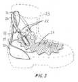
- Fig. 3is a perspective view of the ankle support device as shown installed within a soft-style snowboard boot (shown in partial phantom).
- an ankle support assembly 10constructed in accordance with one embodiment of the present invention.
- the ankle support assembly 10includes a rigid molded heel cup 12 with a slot or pocket 14 formed in the top rear surface of the heel cup.
- the heel cup pocket 14provides "floating" support to the high back, but is also designed to locate and hold the heel in a fixed position, preventing “heel lift” which is detrimental to the control of the system.
- the ankle support assembly 10further includes a rigid or partially rigid high back support 16 having a narrow, rounded bottom end member 18 adapted for coupled insertion within the heel cup pocket 14. Since the bottom end member 18 is not mechanically fixed to the heel cup 12, and since the pocket 14 is larger than the bottom end of the high back, the high back 16 is free to rotate laterally (as indicated by directional arrow A) and shift vertically (as indicated by directional arrow B), thereby giving greater control and freedom of movement to the rider. The high back 16 "floats" in the pocket 14 instead of pivoting about a fixed point. Because of this, the assembly 10 articulates in a manner that closely approximates the actual articulation of the foot and ankle, thereby providing more comfort and freedom than a fixed pivoting assembly.
- the movable "axis of rotation"is significantly lower than the axis of rotation in the fixed pivoting ankle support systems of the prior art, thus allowing the system of the present invention to more closely mimic the ankle's true action.
- the pocket widthis also designed to be greater than the thickness of the bottom end 18 of the high back 16 so that some front-to-back rotation of the high back 16 is also accommodated (as indicated by directional arrow C). This allows for adjustment of the forward lean of the boot.
- the ankle support device 10preferably includes a leash 20 connected between the high back support 16 and heel cup 12 to restrain or limit the total upward range of motion of the high back support or spoiler 16.
- the leash 20prevents the inadvertent decoupling of the high back 16 from the heel cup 12.
- the ankle support device 10may include a length adjustable cable or strap 22 for forward lean control.
- the ankle support assembly 10is shown fitted within a soft-style snowboard boot 23 (shown in phantom).
- the opposite ends of the cable or strap 22are attached to the respective opposite sides of the boot upper 24 at two locations on opposite sides of the foot.
- the cable 22is directed through a guide 26 that goes around rear of the high back support 16.
- the cable 22includes a length adjustable locking mechanism 28 that allows for adjustment of the forward lean of the boot.
- the above-described connection of the length adjustable cable 22 to the boot upper 24 and high back 16permits the boot cuff/high back to slide freely along the length of the cable 22 to allow lateral flexing about the ankle joint with no loss of high back support. This could also be accomplished in either of the following ways, each comprising a separate design. In each case the forward lean system and the high back would be securely connected, so that the vertical component of the strap/cable tension would be balanced by compression in the high back.
Landscapes
- Health & Medical Sciences (AREA)
- General Health & Medical Sciences (AREA)
- Physical Education & Sports Medicine (AREA)
- Epidemiology (AREA)
- Public Health (AREA)
- Footwear And Its Accessory, Manufacturing Method And Apparatuses (AREA)
- Professional, Industrial, Or Sporting Protective Garments (AREA)
- Medicines Containing Plant Substances (AREA)
- Finger-Pressure Massage (AREA)
- Passenger Equipment (AREA)
Abstract
Description
Claims (7)
- An ankle support assembly (10) for use in combination with a soft-style snowboard boot (23) andwhich is effective to provide improved support and motion control for the foot and ankleregion of the snowboard rider, comprising:a) a rigid heel cup (12);b) a high back support (16) for supporting the calf region of the snowboard rider, saidhigh back support (16) including an extension member (18) extending downwardly in the direction ofsaid heel cup (12); andc) coupling means for coupling said extension member of said high back support (16)to said heel cup (12)characterised in that said coupling occurs in a free floating manner which permits said high back support (16) to pivot about apivot axis that is translatable a predetermined amount along transverse, longitudinal andvertical axes of the ankle support assembly (10) so as to enable articulation of said ankle supportassembly in a manner that closely approximates the articulation of the foot and ankle of thesnowboard rider.
- An ankle support assembly according to claim 1, wherein said coupling means includesa pocket (14) formed along an upper rear surface of said heel cup.
- An ankle support assembly according to any of claims 1 to 2, which further includesrestraint means for restraining the amount of vertical translation of said high back support toprevent inadvertent decoupling of said high back support from said heel cup.
- An ankle support assembly according to claim 3, wherein said restraint means includesa tether (20) connected between said high back support (16) and said heel cup (12).
- An ankle support assembly according to any of claims 1 to 4, which further includes alength adjustable cable (22) routed around said high back support an having opposite ends attachableto respective opposite sides of the snowboard boot upper (24) at the location of the ball of the foot,said cable effective to set a forward lean adjustment of said high back support.
- An ankle support assembly according to any of claims 1 to 5, wherein said anklesupport assembly is fashioned as an insert for a soft-style snowboard boot.
- An ankle support assembly according to any of claims 1 to 5, wherein said anklesupport assembly can be positioned between a flexible outer boot portion and padded inner bootportion of a soft-style snowboard boot.
Applications Claiming Priority (3)
| Application Number | Priority Date | Filing Date | Title |
|---|---|---|---|
| US3561997P | 1997-01-17 | 1997-01-17 | |
| US35619P | 1997-01-17 | ||
| PCT/US1998/000336WO1998031247A1 (en) | 1997-01-17 | 1998-01-15 | Improved snowboard boot ankle support assembly |
Publications (3)
| Publication Number | Publication Date |
|---|---|
| EP0961555A1 EP0961555A1 (en) | 1999-12-08 |
| EP0961555A4 EP0961555A4 (en) | 2002-07-17 |
| EP0961555B1true EP0961555B1 (en) | 2003-11-05 |
Family
ID=21883800
Family Applications (1)
| Application Number | Title | Priority Date | Filing Date |
|---|---|---|---|
| EP98901208AExpired - LifetimeEP0961555B1 (en) | 1997-01-17 | 1998-01-15 | Snowboard boot ankle support assembly |
Country Status (13)
| Country | Link |
|---|---|
| US (1) | US6082026A (en) |
| EP (1) | EP0961555B1 (en) |
| KR (1) | KR100515877B1 (en) |
| CN (1) | CN1135080C (en) |
| AT (1) | ATE253305T1 (en) |
| AU (1) | AU5733998A (en) |
| CA (1) | CA2278008C (en) |
| DE (1) | DE69819475T2 (en) |
| DK (1) | DK199901024A (en) |
| ES (1) | ES2210712T3 (en) |
| IS (1) | IS2108B (en) |
| PT (1) | PT961555E (en) |
| WO (1) | WO1998031247A1 (en) |
Families Citing this family (46)
| Publication number | Priority date | Publication date | Assignee | Title |
|---|---|---|---|---|
| US6648365B1 (en) | 1997-01-08 | 2003-11-18 | The Burton Corporation | Snowboard binding |
| JP3014091B2 (en)* | 1997-11-18 | 2000-02-28 | 株式会社シマノ | Back support system for snowboard boots |
| US6189913B1 (en)* | 1997-12-18 | 2001-02-20 | K-2 Corporation | Step-in snowboard binding and boot therefor |
| US5946827A (en)* | 1998-08-03 | 1999-09-07 | Shimano Inc. | Snowboard boot ankle and heel support |
| WO2000010415A1 (en)* | 1998-08-20 | 2000-03-02 | Marcus Schachtschneider | Ankle protection device |
| US6231057B1 (en) | 1998-10-09 | 2001-05-15 | The Burton Corporation | Highback with an adjustable shape |
| US6557865B1 (en) | 1998-10-09 | 2003-05-06 | The Burton Corporation | Highback with adjustable stiffness |
| US6663118B1 (en) | 1998-12-02 | 2003-12-16 | Shimano, Inc. | Snowboard interface with an upper portion that translates and rotates relative to a lower portion |
| US6231066B1 (en)* | 1999-03-03 | 2001-05-15 | Shimano Inc. | Active highback system for a snowboard boot |
| US6422048B1 (en)* | 1999-03-15 | 2002-07-23 | Spoonfish, Inc. | Snowboard security locks |
| US6631919B1 (en)* | 2000-01-06 | 2003-10-14 | The Burton Corporation | Wing-shaped leg support for a highback |
| FR2804339B1 (en)* | 2000-01-28 | 2002-04-19 | Salomon Sa | DEVICE FOR RETAINING A SHOE ON A SNOWBOARD INTENDED FOR SNOW SURFING |
| US6485035B1 (en) | 2000-04-28 | 2002-11-26 | The Burton Corporation | Binding baseplate for a gliding board |
| IT1318533B1 (en) | 2000-05-23 | 2003-08-27 | Alpinestars Res Srl | STRUCTURE TO CONTAIN EXCURSIONS OF THE KNEE BOOT OF A DAMOTOCYCLING BOOTE IN LONGITUDINAL, ROTATORY AND TORSIONAL DIRECTIONS |
| FR2814963B1 (en) | 2000-10-06 | 2003-01-10 | Salomon Sa | DEVICE FOR RETAINING A SHOE ON A SLIDING, RUNNING OR WALKING BOARD FOR THE PRACTICE OF A SPORT |
| US7013586B1 (en) | 2003-01-10 | 2006-03-21 | Nike, Inc. | Article of athletic footwear with a leash |
| US7219444B2 (en)* | 2003-08-26 | 2007-05-22 | K-2 Corporation | Boot liner with ankle and heel volume control |
| KR100466780B1 (en)* | 2004-03-15 | 2005-01-24 | 정영균 | Sports Shoe With Ankle Protector |
| US7334354B2 (en)* | 2004-06-04 | 2008-02-26 | Nike, Inc. | Adjustable ankle support for an article of footwear |
| US7918811B2 (en)* | 2008-08-05 | 2011-04-05 | Adidas International Marketing B.V. | Support device for a joint |
| US8469372B2 (en) | 2008-10-23 | 2013-06-25 | Bryce M. Kloster | Splitboard binding apparatus |
| US9016714B2 (en) | 2009-04-30 | 2015-04-28 | Jf Pelchat Inc. | Binding system for recreational board |
| WO2010124382A1 (en) | 2009-04-30 | 2010-11-04 | Pelchat Jean-Francois | Binding system for recreational board |
| US8438757B2 (en)* | 2009-06-23 | 2013-05-14 | Mark Costin Roser | Human locomotion assisting shoe |
| US9572395B2 (en) | 2009-06-23 | 2017-02-21 | Mark Costin Roser | Human locomotion assisting shoe and clothing |
| WO2011044067A1 (en) | 2009-10-05 | 2011-04-14 | Jacob Bender | Foot binding devices |
| US9402437B2 (en) | 2010-06-21 | 2016-08-02 | Under Armour, Inc. | Foot support article |
| US9707119B2 (en) | 2010-06-21 | 2017-07-18 | Under Armour, Inc. | Foot support article |
| WO2012058451A1 (en)* | 2010-10-27 | 2012-05-03 | Debney Ben C | Snowboard combination boot and binding system |
| JP5212957B1 (en)* | 2011-05-16 | 2013-06-19 | 安男 石黒 | Shoes that can also be used as a chair |
| US11026473B2 (en) | 2011-05-19 | 2021-06-08 | Under Armour, Inc. | Foot support article |
| CA2776110A1 (en)* | 2011-05-19 | 2012-11-19 | Under Armour, Inc. | Foot support article |
| US9238168B2 (en) | 2012-02-10 | 2016-01-19 | Bryce M. Kloster | Splitboard joining device |
| USD689971S1 (en) | 2012-03-15 | 2013-09-17 | NOW Snowboarding Inc. | Snowboard binding |
| US9266010B2 (en) | 2012-06-12 | 2016-02-23 | Tyler G. Kloster | Splitboard binding with adjustable leverage devices |
| US20150216252A1 (en)* | 2014-01-31 | 2015-08-06 | Zubits, Llc | Footwear with magnetic closures |
| CN104544717A (en)* | 2014-11-27 | 2015-04-29 | 彭佳胜 | Waterproof whole-sole breathable shoes |
| DE102015101142A1 (en)* | 2015-01-27 | 2016-07-28 | Dee Luxe Sportartikel Handels Gmbh | Snowboard boots, in particular snowboard touring boots, with rear flexible shaft section |
| US10029165B2 (en) | 2015-04-27 | 2018-07-24 | Bryce M. Kloster | Splitboard joining device |
| US9604122B2 (en) | 2015-04-27 | 2017-03-28 | Bryce M. Kloster | Splitboard joining device |
| WO2018016382A1 (en)* | 2016-07-19 | 2018-01-25 | 株式会社アシックス | Footwear |
| US10588381B2 (en) | 2016-11-21 | 2020-03-17 | Under Armour, Inc. | Footwear with internal harness |
| US10398191B2 (en) | 2017-05-04 | 2019-09-03 | Carl Cox | Ski boot assembly |
| US11117042B2 (en) | 2019-05-03 | 2021-09-14 | Bryce M. Kloster | Splitboard binding |
| US11285377B2 (en) | 2019-06-05 | 2022-03-29 | Harry Jason Talanian | Adjustable boot binding apparatus |
| US11938394B2 (en) | 2021-02-22 | 2024-03-26 | Bryce M. Kloster | Splitboard joining device |
Family Cites Families (16)
| Publication number | Priority date | Publication date | Assignee | Title |
|---|---|---|---|---|
| US2972822A (en)* | 1959-09-17 | 1961-02-28 | William L Wright | Ankle support device |
| FR95015E (en)* | 1965-03-24 | 1970-03-27 | Vogel Raimund W | Low shoes and high shoes with reinforcing or stiffening elements. |
| US3597862A (en)* | 1968-08-01 | 1971-08-10 | Raimund W Vogel | Ski boot |
| US3807062A (en)* | 1971-01-22 | 1974-04-30 | Karku Sport Ab | Athletic boot |
| SE392806B (en)* | 1975-08-22 | 1977-04-25 | P Ancker | SKI SHOES INCLUDING AN INNER SHELL, A SOLE AND AN EXTERNAL ENVIRONMENTAL AND CLIMATE PROTECTION |
| DE3622746A1 (en)* | 1986-07-07 | 1988-01-21 | Markus Laemmert | Binding for monoski |
| US5090138A (en)* | 1990-06-11 | 1992-02-25 | Robert Borden | Spring shoe device |
| US5454173A (en)* | 1990-08-22 | 1995-10-03 | Salomon S.A. | Sports boot with a journalled collar |
| US5056509A (en)* | 1991-01-11 | 1991-10-15 | Swearington Derritt R | Ankle brace |
| IT1253179B (en)* | 1991-07-22 | 1995-07-10 | Nordica Spa | STRUCTURE OF TIGHTENING DEVICE, PARTICULARLY FOR DASCI BOOTS |
| US5435080A (en)* | 1992-12-17 | 1995-07-25 | Meiselman; Jamie | Boot for snowboarding and the like |
| FR2702935B1 (en)* | 1993-03-24 | 1995-06-09 | Salomon Sa | SLIDING SPORTS SHOE. |
| US5505477A (en)* | 1993-07-19 | 1996-04-09 | K-2 Corporation | Snowboard binding |
| DE4333503C2 (en) | 1993-10-01 | 1995-07-27 | Usp Markeing & Vertriebs Gmbh | Snowboard boots |
| US5692765A (en)* | 1995-06-07 | 1997-12-02 | Laughlin; James | Soft boot step-in snowboard binding |
| JP2812912B2 (en)* | 1995-11-10 | 1998-10-22 | 株式会社シマノ | Snowboard boots |
- 1998
- 1998-01-15KRKR10-1999-7006490Apatent/KR100515877B1/ennot_activeExpired - Lifetime
- 1998-01-15DEDE69819475Tpatent/DE69819475T2/ennot_activeExpired - Fee Related
- 1998-01-15CACA002278008Apatent/CA2278008C/ennot_activeExpired - Lifetime
- 1998-01-15USUS09/341,070patent/US6082026A/ennot_activeExpired - Lifetime
- 1998-01-15EPEP98901208Apatent/EP0961555B1/ennot_activeExpired - Lifetime
- 1998-01-15PTPT98901208Tpatent/PT961555E/enunknown
- 1998-01-15ATAT98901208Tpatent/ATE253305T1/ennot_activeIP Right Cessation
- 1998-01-15ESES98901208Tpatent/ES2210712T3/ennot_activeExpired - Lifetime
- 1998-01-15CNCNB988018683Apatent/CN1135080C/ennot_activeExpired - Fee Related
- 1998-01-15AUAU57339/98Apatent/AU5733998A/ennot_activeAbandoned
- 1998-01-15WOPCT/US1998/000336patent/WO1998031247A1/enactiveIP Right Grant
- 1999
- 1999-07-14DKDK199901024Apatent/DK199901024A/ennot_activeApplication Discontinuation
- 1999-07-16ISIS5120Apatent/IS2108B/enunknown
Also Published As
| Publication number | Publication date |
|---|---|
| KR20000070262A (en) | 2000-11-25 |
| CA2278008C (en) | 2005-10-25 |
| DE69819475D1 (en) | 2003-12-11 |
| IS2108B (en) | 2006-05-15 |
| IS5120A (en) | 1999-07-16 |
| PT961555E (en) | 2004-03-31 |
| HK1023923A1 (en) | 2000-09-29 |
| DK199901024A (en) | 1999-07-14 |
| CN1135080C (en) | 2004-01-21 |
| US6082026A (en) | 2000-07-04 |
| AU5733998A (en) | 1998-08-07 |
| ATE253305T1 (en) | 2003-11-15 |
| EP0961555A4 (en) | 2002-07-17 |
| DE69819475T2 (en) | 2004-09-09 |
| ES2210712T3 (en) | 2004-07-01 |
| KR100515877B1 (en) | 2005-09-20 |
| EP0961555A1 (en) | 1999-12-08 |
| CN1243420A (en) | 2000-02-02 |
| CA2278008A1 (en) | 1998-07-23 |
| WO1998031247A1 (en) | 1998-07-23 |
Similar Documents
| Publication | Publication Date | Title |
|---|---|---|
| EP0961555B1 (en) | Snowboard boot ankle support assembly | |
| US6138384A (en) | Snowboard boot with inner stiffening assembly | |
| US5713587A (en) | Attachment system for snowboards | |
| EP0720500B1 (en) | Snowboard binding | |
| US6457736B1 (en) | Active highback system for a snowboard boot | |
| US5647148A (en) | Boot for snowboarding and the like | |
| EP0466032B1 (en) | Downhill ski boot assembly | |
| EP0959702B1 (en) | Snowboard boot and binding | |
| EP1118361B1 (en) | Adjustable strap for use in a snowboard boot and binding system | |
| US3747235A (en) | Lever-type ski boots | |
| US5701689A (en) | Snowboard boot | |
| US6231057B1 (en) | Highback with an adjustable shape | |
| EP1033085B1 (en) | Active highback system for a snowboard boot | |
| US20030193151A1 (en) | Highback formed of multiple materials | |
| HK1023923B (en) | Snowboard boot ankle support assembly | |
| JP4021497B2 (en) | Improved ankle support assembly for snowboard boots |
Legal Events
| Date | Code | Title | Description |
|---|---|---|---|
| PUAI | Public reference made under article 153(3) epc to a published international application that has entered the european phase | Free format text:ORIGINAL CODE: 0009012 | |
| 17P | Request for examination filed | Effective date:19990707 | |
| AK | Designated contracting states | Kind code of ref document:A1 Designated state(s):AT CH DE ES FI FR GB IT LI NL PT SE | |
| A4 | Supplementary search report drawn up and despatched | Effective date:20020531 | |
| AK | Designated contracting states | Kind code of ref document:A4 Designated state(s):AT CH DE ES FI FR GB IT LI NL PT SE | |
| GRAH | Despatch of communication of intention to grant a patent | Free format text:ORIGINAL CODE: EPIDOS IGRA | |
| RTI1 | Title (correction) | Free format text:SNOWBOARD BOOT ANKLE SUPPORT ASSEMBLY | |
| GRAS | Grant fee paid | Free format text:ORIGINAL CODE: EPIDOSNIGR3 | |
| GRAA | (expected) grant | Free format text:ORIGINAL CODE: 0009210 | |
| AK | Designated contracting states | Kind code of ref document:B1 Designated state(s):AT CH DE ES FI FR GB IT LI NL PT SE | |
| REG | Reference to a national code | Ref country code:GB Ref legal event code:FG4D | |
| REG | Reference to a national code | Ref country code:CH Ref legal event code:EP | |
| REF | Corresponds to: | Ref document number:69819475 Country of ref document:DE Date of ref document:20031211 Kind code of ref document:P | |
| REG | Reference to a national code | Ref country code:SE Ref legal event code:TRGR | |
| REG | Reference to a national code | Ref country code:CH Ref legal event code:NV Representative=s name:KIRKER & CIE SA | |
| REG | Reference to a national code | Ref country code:PT Ref legal event code:SC4A Free format text:AVAILABILITY OF NATIONAL TRANSLATION Effective date:20040203 | |
| REG | Reference to a national code | Ref country code:ES Ref legal event code:FG2A Ref document number:2210712 Country of ref document:ES Kind code of ref document:T3 | |
| ET | Fr: translation filed | ||
| PLBE | No opposition filed within time limit | Free format text:ORIGINAL CODE: 0009261 | |
| STAA | Information on the status of an ep patent application or granted ep patent | Free format text:STATUS: NO OPPOSITION FILED WITHIN TIME LIMIT | |
| 26N | No opposition filed | Effective date:20040806 | |
| PGFP | Annual fee paid to national office [announced via postgrant information from national office to epo] | Ref country code:ES Payment date:20080131 Year of fee payment:11 Ref country code:CH Payment date:20080129 Year of fee payment:11 | |
| PGFP | Annual fee paid to national office [announced via postgrant information from national office to epo] | Ref country code:SE Payment date:20080128 Year of fee payment:11 Ref country code:PT Payment date:20080207 Year of fee payment:11 Ref country code:NL Payment date:20080123 Year of fee payment:11 Ref country code:IT Payment date:20080130 Year of fee payment:11 Ref country code:GB Payment date:20080123 Year of fee payment:11 Ref country code:FI Payment date:20080129 Year of fee payment:11 Ref country code:DE Payment date:20080124 Year of fee payment:11 | |
| PGFP | Annual fee paid to national office [announced via postgrant information from national office to epo] | Ref country code:AT Payment date:20080128 Year of fee payment:11 | |
| PGFP | Annual fee paid to national office [announced via postgrant information from national office to epo] | Ref country code:FR Payment date:20080125 Year of fee payment:11 | |
| REG | Reference to a national code | Ref country code:PT Ref legal event code:MM4A Free format text:LAPSE DUE TO NON-PAYMENT OF FEES Effective date:20090715 | |
| REG | Reference to a national code | Ref country code:CH Ref legal event code:PL | |
| EUG | Se: european patent has lapsed | ||
| GBPC | Gb: european patent ceased through non-payment of renewal fee | Effective date:20090115 | |
| NLV4 | Nl: lapsed or anulled due to non-payment of the annual fee | Effective date:20090801 | |
| PG25 | Lapsed in a contracting state [announced via postgrant information from national office to epo] | Ref country code:PT Free format text:LAPSE BECAUSE OF NON-PAYMENT OF DUE FEES Effective date:20090715 Ref country code:LI Free format text:LAPSE BECAUSE OF NON-PAYMENT OF DUE FEES Effective date:20090131 Ref country code:FI Free format text:LAPSE BECAUSE OF NON-PAYMENT OF DUE FEES Effective date:20090115 Ref country code:DE Free format text:LAPSE BECAUSE OF NON-PAYMENT OF DUE FEES Effective date:20090801 Ref country code:CH Free format text:LAPSE BECAUSE OF NON-PAYMENT OF DUE FEES Effective date:20090131 Ref country code:AT Free format text:LAPSE BECAUSE OF NON-PAYMENT OF DUE FEES Effective date:20090115 | |
| REG | Reference to a national code | Ref country code:FR Ref legal event code:ST Effective date:20091030 | |
| PG25 | Lapsed in a contracting state [announced via postgrant information from national office to epo] | Ref country code:NL Free format text:LAPSE BECAUSE OF NON-PAYMENT OF DUE FEES Effective date:20090801 Ref country code:GB Free format text:LAPSE BECAUSE OF NON-PAYMENT OF DUE FEES Effective date:20090115 | |
| REG | Reference to a national code | Ref country code:ES Ref legal event code:FD2A Effective date:20090116 | |
| PG25 | Lapsed in a contracting state [announced via postgrant information from national office to epo] | Ref country code:FR Free format text:LAPSE BECAUSE OF NON-PAYMENT OF DUE FEES Effective date:20090202 Ref country code:ES Free format text:LAPSE BECAUSE OF NON-PAYMENT OF DUE FEES Effective date:20090116 | |
| PG25 | Lapsed in a contracting state [announced via postgrant information from national office to epo] | Ref country code:IT Free format text:LAPSE BECAUSE OF NON-PAYMENT OF DUE FEES Effective date:20090115 | |
| PG25 | Lapsed in a contracting state [announced via postgrant information from national office to epo] | Ref country code:SE Free format text:LAPSE BECAUSE OF NON-PAYMENT OF DUE FEES Effective date:20090116 |