EP0960039B1 - Seat occupant sensing system - Google Patents
Seat occupant sensing systemDownload PDFInfo
- Publication number
- EP0960039B1 EP0960039B1EP98905035AEP98905035AEP0960039B1EP 0960039 B1EP0960039 B1EP 0960039B1EP 98905035 AEP98905035 AEP 98905035AEP 98905035 AEP98905035 AEP 98905035AEP 0960039 B1EP0960039 B1EP 0960039B1
- Authority
- EP
- European Patent Office
- Prior art keywords
- seat
- sensors
- sensing system
- occupant sensing
- rigid member
- Prior art date
- Legal status (The legal status is an assumption and is not a legal conclusion. Google has not performed a legal analysis and makes no representation as to the accuracy of the status listed.)
- Expired - Lifetime
Links
- 230000005291magnetic effectEffects0.000claimsdescription24
- 238000000034methodMethods0.000claimsdescription4
- 230000008569processEffects0.000claimsdescription4
- 238000006073displacement reactionMethods0.000claimsdescription3
- 239000000463materialSubstances0.000description11
- 239000011152fibreglassSubstances0.000description4
- 230000003319supportive effectEffects0.000description4
- 230000007423decreaseEffects0.000description3
- 230000004907fluxEffects0.000description3
- 230000004913activationEffects0.000description2
- 230000000295complement effectEffects0.000description2
- 230000000694effectsEffects0.000description2
- 230000005294ferromagnetic effectEffects0.000description2
- 229920001821foam rubberPolymers0.000description2
- 230000000284resting effectEffects0.000description2
- 230000035945sensitivityEffects0.000description2
- 230000003068static effectEffects0.000description2
- 229910000831SteelInorganic materials0.000description1
- 229910052782aluminiumInorganic materials0.000description1
- XAGFODPZIPBFFR-UHFFFAOYSA-NaluminiumChemical compound[Al]XAGFODPZIPBFFR-UHFFFAOYSA-N0.000description1
- 230000005290antiferromagnetic effectEffects0.000description1
- 230000008901benefitEffects0.000description1
- 230000002860competitive effectEffects0.000description1
- 230000006835compressionEffects0.000description1
- 238000007906compressionMethods0.000description1
- 239000012141concentrateSubstances0.000description1
- 239000002772conduction electronSubstances0.000description1
- 230000008878couplingEffects0.000description1
- 238000010168coupling processMethods0.000description1
- 238000005859coupling reactionMethods0.000description1
- 238000001803electron scatteringMethods0.000description1
- 238000005516engineering processMethods0.000description1
- 239000004744fabricSubstances0.000description1
- 239000010408filmSubstances0.000description1
- 238000009434installationMethods0.000description1
- 230000007246mechanismEffects0.000description1
- 229910052751metalInorganic materials0.000description1
- 239000002184metalSubstances0.000description1
- 150000002739metalsChemical class0.000description1
- 230000002093peripheral effectEffects0.000description1
- 230000010287polarizationEffects0.000description1
- 230000000717retained effectEffects0.000description1
- 239000007787solidSubstances0.000description1
- 239000010959steelSubstances0.000description1
- 239000010409thin filmSubstances0.000description1
- 125000000391vinyl groupChemical group[H]C([*])=C([H])[H]0.000description1
- 229920002554vinyl polymerPolymers0.000description1
- 238000005303weighingMethods0.000description1
Images


Classifications
- B—PERFORMING OPERATIONS; TRANSPORTING
- B60—VEHICLES IN GENERAL
- B60R—VEHICLES, VEHICLE FITTINGS, OR VEHICLE PARTS, NOT OTHERWISE PROVIDED FOR
- B60R21/00—Arrangements or fittings on vehicles for protecting or preventing injuries to occupants or pedestrians in case of accidents or other traffic risks
- B60R21/01—Electrical circuits for triggering passive safety arrangements, e.g. airbags, safety belt tighteners, in case of vehicle accidents or impending vehicle accidents
- B60R21/015—Electrical circuits for triggering passive safety arrangements, e.g. airbags, safety belt tighteners, in case of vehicle accidents or impending vehicle accidents including means for detecting the presence or position of passengers, passenger seats or child seats, and the related safety parameters therefor, e.g. speed or timing of airbag inflation in relation to occupant position or seat belt use
- B60R21/01512—Passenger detection systems
- B60R21/01516—Passenger detection systems using force or pressure sensing means
- B—PERFORMING OPERATIONS; TRANSPORTING
- B60—VEHICLES IN GENERAL
- B60N—SEATS SPECIALLY ADAPTED FOR VEHICLES; VEHICLE PASSENGER ACCOMMODATION NOT OTHERWISE PROVIDED FOR
- B60N2/00—Seats specially adapted for vehicles; Arrangement or mounting of seats in vehicles
- B60N2/002—Seats provided with an occupancy detection means mounted therein or thereon
- B60N2/0021—Seats provided with an occupancy detection means mounted therein or thereon characterised by the type of sensor or measurement
- B60N2/0024—Seats provided with an occupancy detection means mounted therein or thereon characterised by the type of sensor or measurement for identifying, categorising or investigation of the occupant or object on the seat
- B—PERFORMING OPERATIONS; TRANSPORTING
- B60—VEHICLES IN GENERAL
- B60N—SEATS SPECIALLY ADAPTED FOR VEHICLES; VEHICLE PASSENGER ACCOMMODATION NOT OTHERWISE PROVIDED FOR
- B60N2/00—Seats specially adapted for vehicles; Arrangement or mounting of seats in vehicles
- B60N2/002—Seats provided with an occupancy detection means mounted therein or thereon
- B60N2/0021—Seats provided with an occupancy detection means mounted therein or thereon characterised by the type of sensor or measurement
- B60N2/003—Seats provided with an occupancy detection means mounted therein or thereon characterised by the type of sensor or measurement characterised by the sensor mounting location in or on the seat
- B60N2/0031—Seats provided with an occupancy detection means mounted therein or thereon characterised by the type of sensor or measurement characterised by the sensor mounting location in or on the seat mounted on the frame
- B—PERFORMING OPERATIONS; TRANSPORTING
- B60—VEHICLES IN GENERAL
- B60N—SEATS SPECIALLY ADAPTED FOR VEHICLES; VEHICLE PASSENGER ACCOMMODATION NOT OTHERWISE PROVIDED FOR
- B60N2/00—Seats specially adapted for vehicles; Arrangement or mounting of seats in vehicles
- B60N2/002—Seats provided with an occupancy detection means mounted therein or thereon
- B60N2/0021—Seats provided with an occupancy detection means mounted therein or thereon characterised by the type of sensor or measurement
- B60N2/0035—Seats provided with an occupancy detection means mounted therein or thereon characterised by the type of sensor or measurement characterised by the sensor data transmission, e.g. wired connections or wireless transmitters therefor; characterised by the sensor data processing, e.g. seat sensor signal amplification or electric circuits for providing seat sensor information
- B—PERFORMING OPERATIONS; TRANSPORTING
- B60—VEHICLES IN GENERAL
- B60N—SEATS SPECIALLY ADAPTED FOR VEHICLES; VEHICLE PASSENGER ACCOMMODATION NOT OTHERWISE PROVIDED FOR
- B60N2/00—Seats specially adapted for vehicles; Arrangement or mounting of seats in vehicles
- B60N2/58—Seat coverings
- B—PERFORMING OPERATIONS; TRANSPORTING
- B60—VEHICLES IN GENERAL
- B60N—SEATS SPECIALLY ADAPTED FOR VEHICLES; VEHICLE PASSENGER ACCOMMODATION NOT OTHERWISE PROVIDED FOR
- B60N2/00—Seats specially adapted for vehicles; Arrangement or mounting of seats in vehicles
- B60N2/70—Upholstery springs ; Upholstery
- B60N2/7094—Upholstery springs
- B—PERFORMING OPERATIONS; TRANSPORTING
- B60—VEHICLES IN GENERAL
- B60R—VEHICLES, VEHICLE FITTINGS, OR VEHICLE PARTS, NOT OTHERWISE PROVIDED FOR
- B60R21/00—Arrangements or fittings on vehicles for protecting or preventing injuries to occupants or pedestrians in case of accidents or other traffic risks
- B60R21/01—Electrical circuits for triggering passive safety arrangements, e.g. airbags, safety belt tighteners, in case of vehicle accidents or impending vehicle accidents
- B60R21/015—Electrical circuits for triggering passive safety arrangements, e.g. airbags, safety belt tighteners, in case of vehicle accidents or impending vehicle accidents including means for detecting the presence or position of passengers, passenger seats or child seats, and the related safety parameters therefor, e.g. speed or timing of airbag inflation in relation to occupant position or seat belt use
- B60R21/01512—Passenger detection systems
- B60R21/01516—Passenger detection systems using force or pressure sensing means
- B60R21/0152—Passenger detection systems using force or pressure sensing means using strain gauges
- G—PHYSICS
- G01—MEASURING; TESTING
- G01G—WEIGHING
- G01G19/00—Weighing apparatus or methods adapted for special purposes not provided for in the preceding groups
- G01G19/40—Weighing apparatus or methods adapted for special purposes not provided for in the preceding groups with provisions for indicating, recording, or computing price or other quantities dependent on the weight
- G01G19/413—Weighing apparatus or methods adapted for special purposes not provided for in the preceding groups with provisions for indicating, recording, or computing price or other quantities dependent on the weight using electromechanical or electronic computing means
- G01G19/414—Weighing apparatus or methods adapted for special purposes not provided for in the preceding groups with provisions for indicating, recording, or computing price or other quantities dependent on the weight using electromechanical or electronic computing means using electronic computing means only
- G01G19/4142—Weighing apparatus or methods adapted for special purposes not provided for in the preceding groups with provisions for indicating, recording, or computing price or other quantities dependent on the weight using electromechanical or electronic computing means using electronic computing means only for controlling activation of safety devices, e.g. airbag systems
- B—PERFORMING OPERATIONS; TRANSPORTING
- B60—VEHICLES IN GENERAL
- B60N—SEATS SPECIALLY ADAPTED FOR VEHICLES; VEHICLE PASSENGER ACCOMMODATION NOT OTHERWISE PROVIDED FOR
- B60N2210/00—Sensor types, e.g. for passenger detection systems or for controlling seats
- B60N2210/10—Field detection presence sensors
- B60N2210/14—Inductive; Magnetic field
- B—PERFORMING OPERATIONS; TRANSPORTING
- B60—VEHICLES IN GENERAL
- B60N—SEATS SPECIALLY ADAPTED FOR VEHICLES; VEHICLE PASSENGER ACCOMMODATION NOT OTHERWISE PROVIDED FOR
- B60N2210/00—Sensor types, e.g. for passenger detection systems or for controlling seats
- B60N2210/40—Force or pressure sensors
- B60N2210/42—Strain gauges
- B—PERFORMING OPERATIONS; TRANSPORTING
- B60—VEHICLES IN GENERAL
- B60N—SEATS SPECIALLY ADAPTED FOR VEHICLES; VEHICLE PASSENGER ACCOMMODATION NOT OTHERWISE PROVIDED FOR
- B60N2230/00—Communication or electronic aspects
- B60N2230/10—Wired data transmission
Definitions
- a safety devicesuch as airbags and seat belt pretensioners to protect persons occupying various seats in the vehicle. If a seat is unoccupied or is occupied by a person of a particular size, it may not be necessary to activate a safety device associated with that seat. Furthermore, if a seat is occupied by a person of a particular size the manner in which a safety device is employed may be varied accordingly.
- One indicator of the seat occupant's sizeis the occupant's weight. In the case of an infant, the combined weight of the infant and an infant safety seat is useful as an indicator of occupant size.
- FIG. 1is an exploded isometric view of a typical prior art vehicle seat.
- FIG. 2is a perspective view of the bottom side of a prior art seat cushion used with the prior art seat shown in FIG. 1.
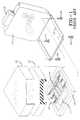
- FIG. 3is an exploded isometric view of a vehicle seat equipped with an occupant sensing apparatus in accordance with the present invention.
- FIG. 4is a front elevation view of a vehicle seat equipped with an occupant sensing apparatus in accordance with the present invention.
- FIG. 5is a side elevation view of the vehicle seat equipped with an occupant sensing apparatus of FIG. 4.
- FIG. 6is a top view of the vehicle seat equipped with an occupant sensing apparatus of FIG. 4.
- FIG. 7Ais a perspective view of the top side of a frame with sensors mounted thereon.
- FIG. 7Bis a perspective view of the bottom side the frame with sensors mounted thereon of FIG. 7A.
- FIG. 8is a cross-sectional side view of the vehicle seat equipped with an occupant sensing apparatus of FIG. 4 taken along section line 8-8.
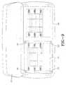
- FIG. 9is a top view of a vehicle bench type vehicle seat equipped with an occupant sensing apparatus in accordance with the present invention.
- FIG. 10is an enlarged fragmentary view of a sensor located between rigid components of a vehicle seat equipped with an occupant sensing apparatus in accordance with the present invention.
- FIG. 11is a schematic view of an occupant sensing apparatus in accordance with the present invention.
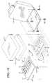
- FIG. 12is an exploded isometric view of an alternative embodiment vehicle seat equipped with an occupant sensing apparatus in accordance with the present invention.
- FIG. 13a cross-sectional side view of the vehicle seat equipped with an occupant sensing apparatus of FIG. 12.
- FIG. 14is an enlarged fragmentary view of a sensor located between rigid components of the alternative vehicle seat design of FIG. 12 which is equipped with an occupant sensing apparatus in accordance with the present invention.
- FIG. 15a cross-sectional side view of a vehicle seat equipped with an alternative embodiment occupant sensing apparatus in accordance with the present invention.
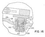
- FIG. 16is an enlarged fragmentary view of a sensor located between rigid components of a vehicle seat equipped with an occupant sensing apparatus in accordance with the present invention
- FIG. 17is a side elevational cross-sectional view of the alternative sensor of FIG. 15.
- FIG. 18is a pictorial plan view of a Giant Magnetoresistive (GMR) circuit employed in the sensor of FIG. 17.
- GMRGiant Magnetoresistive
- FIG. 1there is shown an exploded view of a typical prior art vehicle seat.
- a vehicle seathas a seat cushion 10 and a seat back 12.
- the seat backmay have a head rest 13 associated therewith.
- the seat backmay be pivotally attached to the remainder of the seat.
- the seat cushion 10is made of a comfortable, supportive but compressible material, for example foam rubber.
- the seathas a rigid seat support member 16, sometimes referred to as the seat frame.
- the rigid seat support membermay be unitary, as shown in FIG. 1, with a cross member extending between two side rails, or the side rails may only be joined to one another by the seat back and maintained parallel to one another by fastening the seat frame to legs which extend between the seat frame and the floor of the vehicle.
- a seat pan 18supports the seat cushion 10, which is adapted to be secured thereto by having a bottom side 11 that is contoured, as shown in FIG. 2, to be complementary to the seat pan 18.
- the seat panhas a generally rectangular shape which may be adapted to the design of a particular seat cushion and seat frame. As shown in FIG. 1, the perimeter of the sear pan is bent to form peripheral walls which may, or may not, have a second horizontal portion associated therewith.
- a supportive cushioning elastic structurecomprising 25 comprising springs and straps, or any other suitable support members, extends across the opening in the seat pan 18 to provide support for the seat cushion 10.
- the seat frame 16 and the seat pan 18are fastened to one another in a vertically juxtaposed relationship.
- the means for fastening the rigid seat support member and the seat pan 18 to one anotherare a plurality of threaded fasteners 24.
- the threaded fastenersdo not extend through the uppermost surface 26 of the seat pan, but rather are attached to the seat pan in depressions located in the upper surface of the seat pan or attach to a lower horizontally extending portion of the seat pan.
- the upholstery 14is a sheet material which overlies the seat cushion 10 and is secured to the seat pan 18. Examples of sheet materials used as upholstery are fabrics, vinyls and leathers.
- FIGS. 3 to 6there are shown exploded, front elevation, side elevation and top views, respectively, of a vehicle seat equipped with an occupant sensing apparatus in accordance with the present invention.
- a vehicle seatequipped with an occupant sensing apparatus in accordance with the present invention.
- the design of various structural components of a vehicle seatcan vary from one make and model of vehicle to another, with the vehicle seat shown being merely exemplary of a vehicle seat that may be employed in the practice of the present invention.
- the present inventiondoes, however, apply to seats in general and may be employed not only with vehicle seats but also any seat where it is desired to ascertain whether or not the seat is occupied and the weight of a seat occupant.
- the vehicle seathas a seat cushion 10 and a seat back 12.
- the seat backmay have a head rest 13 associated therewith.
- the seat backmay be pivotally attached to the remainder of the seat, as best seen in FIG. 5.
- seat cushion 10is made of a comfortable, supportive but compressible material, for example foam rubber.
- the seat frame 16is substantially like the prior art seat frame described above with reference to FIG. 1.
- the seat pan 18 which supports the seat cushion 10is substantially like the seat pan described above with respect to FIG. 1 and is attached to the seat frame 16 using threaded fasteners 24 in substantially the same manner as described above.
- the upholstery 14, as in the prior art,is a sheet material overlying the seat cushion 10 and secured to the seat pan 18.
- a seat occupant sensing system of the present inventionhas a seat pan 18 with a rigid member 19 disposed vertically above the seat pan in a spaced apart vertically juxtaposed relationship with the seat pan.
- FIGS. 7A and 7Bthere are shown perspective views of the top side and bottom side, respectively, of a frame 19 with sensors 20 mounted thereon.
- the rigid member 19is a frame which has a generally rectangular shape and a sensor 20 is located in the vicinity of each corner of the frame.
- the supportive cushioning elastic structure 25comprising springs and straps, or any other suitable support members, which in the prior art extends across the opening in the seat pan 18 to provide support for the seat cushion 10 instead extends across the frame 19. This feature prevents the springs from contacting both the seat pan and the frame, therefore potentially transferring forces from the frame to the seat pan.
- the rigid member 19underlies a portion of the seat cushion 10 and may be made of any suitable material such as steel or aluminum.
- the frame 19includes a plate 50 which is located to be complementary to the anti-submarining portion 51 of the seat pan 18.
- the anti-submarining portion of a seat panrestricts the tendency of a belted seat occupant to slide forward during a rapid deceleration of the vehicle.
- At least two sensors 20are interposed between the rigid member 19, or frame, and the seat pan 18 such that all of the force transferred from the rigid member to the seat pan is transferred via the sensors.
- the sensorssense the magnitude of the force transferred therethrough and send signals to a device (not shown) which processes the signals to determine the weight that the portion of the seat cushion which the rigid member 19 underlies is bearing.
- Each sensor 20may be, for example, a strain gauge, a load cell or a variable resistance pressure sensor.
- a working prototype of a vehicle seat equipped with an occupant sensing apparatus in accordance with the present inventionemployed four sensors which were Model 14 compression-only subminiature load cells purchased from Sensotec, Inc. of 1200 Chesapeake Avenue, Columbus, Ohio U.S.A. These sensors had a range of either 45.4 kilograms or 113.5 kilograms and a seat could be equipped with only one size sensor or a combination of sizes. For example, 113.5 kilogram sensors could be used towards the front of the seat and 45.4 kilogram sensors could be used towards the rear of the seat. The height of these sensors is 3.8 millimeters. If desired, at least one of the sensors may be one type of sensor, while the other sensor (s) may be another type of sensor.
- the surface of the rigid member 19 which is proximal to a sensor 20is not substantially flat, it is desirable with these commercially available sensors to place a shim of some sort between the sensor and the rigid member to improve the transfer of forces from the rigid member to the sensor.
- the installation of the seat occupant sensing system into the seatis preferably facilitated by securing the sensors in place on the rigid member (frame) and thereafter placing the resultant assembly in a vertically juxtaposed relationship with the seat pan, with the sensors resting on the vertically uppermost surface of the seat pan 18.
- each sensorhas a plurality of electrical leads 21,22 extending therefrom for communicating with a device (not shown) which processes the signals to determine the weight that the portion of the seat cushion which the rigid member underlies is bearing.
- the vertically spaced apart relationship of the rigid member 19 (frame) and the seat pan 18is illustrated very well in FIG. 10. The distance that the rigid member (frame) is spaced apart from the seat pan 18 is the height of the sensor disposed therebetween.
- the portion of the seat cushion 10 which the rigid member 19 underliesis preferably spaced apart from a rear edge of the seat cushion. This feature minimizes the sensing of forces which are transferred from the seat back to the seat pan 18 via the sensors. This is important in the instance where a person seated in the rear seat of an automobile leans against the back of the front seat and could influence the forces transferred to the seat pan. It has been demonstrated that the seat occupant sensing system of the present invention is capable of determining the presence and weight of a seat occupant with good accuracy.
- the rigid member 19 and the seat pan 18are at least partially retained in the vertically juxtaposed relationship by a tension member.
- the tension memberis a sheet material 14 overlying the seat cushion 10 and secured to the seat pan 18.
- the sheet materialis commonly referred to as the seat cover or upholstery.
- the perimeter of the sheet materialmay have clips or a deformable strip associated therewith which can clip onto or be bent around an edge of the seat pan.
- FIG. 9there is shown a top view of a vehicle bench type seat equipped with an occupant sensing apparatus employing a rigid member 19 and sensors 20 in accordance with the present invention. If it is desired to determine the presence and size of an occupant of the passenger side of a front bench seat of a vehicle, the occupant sensing system of the present invention may be incorporated into only the passenger side of the bench seat as illustrated in FIG. 9.
- FIG. 11there is shown a schematic view of an occupant sensing apparatus in accordance with the present invention.
- a signal from each sensoris passed through an amplifier to a device, such as a microprocessor which processes the signal, or signals, to determine the weight that the rigid seat pan member is bearing.
- a devicesuch as a microprocessor which processes the signal, or signals, to determine the weight that the rigid seat pan member is bearing.
- Algorithms to translate a signal to a weightare well known and are used for example in electronic bathroom scales. The algorithm must take into account the weight of the seat cushion and the rigid seat pan member in determining the weight of the seat occupant. Of course if the weight of the seat occupant is determined to be zero, the seat is unoccupied.
- This weight determining devicedetermines the weight that the rigid seat pan is bearing and is preferably a controller which controls the activation of at least one safety device for an occupant of the seat based upon the occupant's weight.
- the controllercontrols, for example, the activation of an inflatable vehicle occupant restraint or a seat belt pretensioner.
- the controllermay control the manner in which an activated safety device operates, for example controlling the speed at which an airbag is inflated or the amount of seat belt slack which is to be taken up by the pretensioner.
- the seat occupant sensing system disclosed hereinmay determine the presence or absence of an object or person on a seat cushion, and if present, the weight of the person or object on the seat cushion. Based upon these determination, the device may activate one or more safety devices, and/or control the manner in which an activated safety device operates.
- a seat frameis not part of the structure of the seat.
- a fiberglass tray 60can be placed above the seat pan 16.
- the fiberglass tray 60thus forms the seat frame and transmits substantially all the load imposed on the seat by the seat occupant onto sensors which measure the weight of the occupant. In this way the seat occupant sensing system of this invention can be employed with a wider range of car seats.
- FIGS.12-14illustrate how the fiberglass tray 60 substitutes for the frame 19.
- the fiberglass tray 60provides a lightweight rigid member which can receive the distributed load imposed by a seat occupant on the cushion 10 and concentrate the distributed load on four points where the sensors 20 can measure the imposed load.
- the tray 60requires stiffness, and must be contoured so the seat remains comfortable to the occupant. At the same time the tray must be of relatively low cost and light weight is also a consideration.
- FIG. 15An alternative embodiment seat occupant sensing apparatus 100 of this invention, shown in FIG. 15, employs a sensor 102, shown in FIG. 18, which is based on the Giant Magnetoresistive (GMR) effect.
- the sensor 102as shown in FIGS. 15, 16 and 17 is positioned in a housing 104 which contains a spring 106 which supports a plunger 108.
- the plunger 108contains a permanent magnet 110 which is held above the GMR sensor 102.
- a cap 112retains the plunger 108 and the spring 106 within the housing 104.
- a button 114overlies the plunger 108 and extends through an opening in the cap 112. A force transmitted to the button 114 moves the plunger 108 containing the magnet 110 downwardly towards the sensor 102.
- the seat pan 120as shown in FIGS.15 and 16, is slightly modified from the seat pan 18 shown in FIGS. 3 and 8.
- the seat pan 120has bosses 122 which reinforce holes 124 formed in the seat pan.
- the holes 124are sized to receive the housings 104 of the force measuring sensors 116.
- the retaining caps 112support the measuring sensors 116 on the upper surface 126 of the seat pan 120.
- the seat frame 118is positioned above the seat pan 120 and engages and is supported on the buttons 114 of four force measuring sensors 116.
- the seat pan 120is mounted to a seat frame 140 which in turn is mounted to the floor 142 of a car or other vehicle. In this way the seat pan 120 is connected to a vehicle (not shown).
- the weight of the occupant resting on the seat cushion 128is supported by the buttons 114 of the force measuring sensors 116.
- the plungers 108 positioned beneath the buttons 114cause the deflection of the springs 106 which allow the permanent magnets 110 to move downwardly towards the GMR sensors 102.
- the amount of downward movement of the permanent magnets 110is controlled by the spring constant of the springs 106.
- the force measuring sensors 116incorporate GMR sensors 102 which sense static magnetic fields.
- the sensors 102do not directly support the measured load and have no physical engagement with any moving or load supporting structure.
- the GMR sensors 102utilize an effect discovered in 1988, in which certain thin film devices are able to detect static magnetic fields.
- GMR sensorsutilize resistors built up of thin magnetic film a few nanometers thick separated by equally thin nonmagnetic layers.
- a decrease in resistance of between about 10 and 20 percent in the built-up resistorsis observed when a magnetic field is applied.
- the physical explanation for the decrease in resistanceis the spin dependence of electron scattering and the spin polarization of conduction electrons in ferromagnetic metals.
- the extremely thin adjacent magnetic layerscouple antiferromagnetically to each other so that the magnetic moments of each magnetic layer are aligned antiparallel to adjacent magnetic layers. Electrons, spin polarized in one magnetic layer, are likely to be scattered as they move between adjacent layers. Frequent scattering results in high resistance. An external magnetic field overcomes the antiferromagnetic coupling and produces parallel alignment of moments in adjacent ferromagnetic layers. This decreases scattering and thus device resistance.
- Groups of four resistors based on the GMR technologyare arranged in a Wheatstone bridge and two legs of the bridge are shielded from the applied magnetic fields. The other two legs are positioned between the magnetic shields 130 which are shown schematically in FIG. 18.
- the magnetic shieldsact as flux concentrators to produce a device of tailored sensitivity to a magnetic flux of a selected intensity.
- a standard voltageis supplied to the solid state device 132 and a voltage is read out of the device 132 which is predictably related or proportional to the magnetic field to which the device is exposed.
- the deviceshave an axis 134 of sensitivity which is produced by the orientation of the magnetic flux shields 130 as shown in FIG. 18.
- GMR sensorsare available from Nonvolatile Electronics Inc. of 11409 Valley View Rd., Eden Prairie, Minnesota, U.S.A.. GMR sensors are small, highly sensitive devices which have exceptional temperature stability, deliver high signal levels and require very little power and cost less than many competitive devices. All these factors are important in devices used in automobile safety applications.
- the force measuring sensors 116are employed as part of a system for deploying an air bag and will typically be used with an amplifier and microprocessor as shown in FIG. 11.
- the micro processorwill incorporate logic which analyzes data from crash detecting sensors and data indicating the presence and weight of an occupant in the front passenger seat of an automobile and other data which may be relevant from additional sensors and will deploy or not deploy an air bag based on logic and sensor inputs.
- sensorswhich sense loads or displacement can be employed with the seat occupant sensing system of this invention.
- the coil spring shown in the force measuring sensors 116may employ coils which are round in cross-section or flat and that the size of the cross-section together with the material and the material modulus will control the spring constant. Further, the spring employed in the force measuring sensor 116 could use other types of springs such as Belleville springs, or gas springs.
- the seat frame 140may incorporate an adjustment mechanism which allows motion of the frame with respect to the car floor or allows motion of the seat pan 120 with respect to the frame 140.
Landscapes
- Engineering & Computer Science (AREA)
- Mechanical Engineering (AREA)
- Aviation & Aerospace Engineering (AREA)
- Transportation (AREA)
- Physics & Mathematics (AREA)
- Mathematical Physics (AREA)
- Theoretical Computer Science (AREA)
- Computer Networks & Wireless Communication (AREA)
- General Physics & Mathematics (AREA)
- Seats For Vehicles (AREA)
- Air Bags (AREA)
Description
Claims (10)
- A seat occupant sensing system comprising:(a) a seat pan (18);(b) a rigid member (19) disposed vertically abovethe seat pan in a spaced apart vertically juxtaposedrelationship with the seat pan, the rigid memberunderlying a portion of a seat cushion (10); and(c) at least two sensors (20) interposed betweenthe rigid member and the seat pan such that all of theforce transferred from the rigid member to the seatpan is transferred via the sensors which sense themagnitude of the force transferred therethrough andsend signals to a signal processing device whichprocesses the signals from the sensors to determinethe weight that the portion of the seat cushion isbearing.
- A seat occupant sensing system according toclaim 1 wherein the rigid member (19) has a generallyrectangular shape and a sensor (20) is located in thevicinity of each corner of the rigid member.
- A seat occupant sensing system according toeither of claims 1 or 2 wherein at least one of thesensors (20) is a strain gauge.
- A seat occupant sensing system according toeither of claims 1 or 2 wherein at least one of thesensors (20) is a load cell.
- A seat occupant sensing system according toeither of claims 1 or 2 wherein at least one of thesensors (20) is a variable resistance pressure sensor.
- A seat occupant sensing system according toeither of claims 1 or 2 wherein at least one of thesensors (20) comprises: a magnet (110); a magneticfield sensor (102) spaced from the magnet; and a means(106) for resiliently resisting displacement of themagnet towards the magnetic field sensor so that thedisplacement of the magnet is predictably related tothe applied force.
- A seat occupant sensing system according toclaim 6 wherein the magnetic field sensor (102) is ofthe GMR type.
- A seat occupant sensing system according toeither of claims 1 or 2 wherein at least one of thesensors (20) comprises: a housing; a magnetic fieldsensor (102) positioned within the housing; a plunger(108) mounted above the magnetic field sensor; amagnet (110) mounted to the plunger and positionedabove the magnetic field sensor; and a spring (106)positioned to bias the plunger and the magnet awayfrom the magnetic field sensor, wherein the housing ismounted to the seat pan (18), and the plunger engagesthe rigid member (19).
- A seat occupant sensing system according toclaim 8 wherein the magnetic field sensor (102) is ofthe GMR type.
- A seat occupant sensing system according toany of the preceding claims wherein the system furthercomprises a controller which controls the operation ofat least one safety device for an occupant of the seat based upon the weight that the portion of the seatcushion (10) is bearing.
Applications Claiming Priority (5)
| Application Number | Priority Date | Filing Date | Title |
|---|---|---|---|
| US08/801,928US5810392A (en) | 1997-02-15 | 1997-02-15 | Seat occupant sensing system |
| US801928 | 1997-02-15 | ||
| US19995 | 1998-02-06 | ||
| US09/019,995US5971432A (en) | 1997-02-15 | 1998-02-06 | Seat occupant sensing system |
| PCT/US1998/002576WO1998035861A1 (en) | 1997-02-15 | 1998-02-10 | Seat occupant sensing system |
Publications (3)
| Publication Number | Publication Date |
|---|---|
| EP0960039A1 EP0960039A1 (en) | 1999-12-01 |
| EP0960039A4 EP0960039A4 (en) | 2000-10-04 |
| EP0960039B1true EP0960039B1 (en) | 2003-01-02 |
Family
ID=26692863
Family Applications (1)
| Application Number | Title | Priority Date | Filing Date |
|---|---|---|---|
| EP98905035AExpired - LifetimeEP0960039B1 (en) | 1997-02-15 | 1998-02-10 | Seat occupant sensing system |
Country Status (5)
| Country | Link |
|---|---|
| US (1) | US5971432A (en) |
| EP (1) | EP0960039B1 (en) |
| JP (1) | JP2001512573A (en) |
| DE (1) | DE69810445T2 (en) |
| WO (1) | WO1998035861A1 (en) |
Cited By (7)
| Publication number | Priority date | Publication date | Assignee | Title |
|---|---|---|---|---|
| US7405370B2 (en) | 2004-10-27 | 2008-07-29 | Lear Corporation | Vehicle occupant sensing system having enclosed sensor assembly |
| US10670479B2 (en) | 2018-02-27 | 2020-06-02 | Methode Electronics, Inc. | Towing systems and methods using magnetic field sensing |
| US10696109B2 (en) | 2017-03-22 | 2020-06-30 | Methode Electronics Malta Ltd. | Magnetolastic based sensor assembly |
| US11084342B2 (en) | 2018-02-27 | 2021-08-10 | Methode Electronics, Inc. | Towing systems and methods using magnetic field sensing |
| US11135882B2 (en) | 2018-02-27 | 2021-10-05 | Methode Electronics, Inc. | Towing systems and methods using magnetic field sensing |
| US11221262B2 (en) | 2018-02-27 | 2022-01-11 | Methode Electronics, Inc. | Towing systems and methods using magnetic field sensing |
| US11491832B2 (en) | 2018-02-27 | 2022-11-08 | Methode Electronics, Inc. | Towing systems and methods using magnetic field sensing |
Families Citing this family (105)
| Publication number | Priority date | Publication date | Assignee | Title |
|---|---|---|---|---|
| US6689962B2 (en)* | 1995-06-07 | 2004-02-10 | Automotive Technologies International, Inc | Weight measuring system and method used with a spring system of a seat |
| US6891111B1 (en) | 1994-02-04 | 2005-05-10 | Siemens Vdo Automotive Corporation | Signal processing in a vehicle classification system |
| US7330784B2 (en)* | 1998-11-17 | 2008-02-12 | Automotive Technologies International, Inc. | Weight measuring systems and methods for vehicles |
| US7387183B2 (en)* | 1995-06-07 | 2008-06-17 | Automotive Technologies International, Inc. | Weight measuring systems and methods for vehicles |
| US20070135982A1 (en) | 1995-06-07 | 2007-06-14 | Automotive Technologies International, Inc. | Methods for Sensing Weight of an Occupying Item in a Vehicular Seat |
| US6364352B1 (en)* | 1997-07-09 | 2002-04-02 | Peter Norton | Seat occupant weight sensing system |
| KR20010031876A (en) | 1997-11-12 | 2001-04-16 | 웰스 러셀 씨 | A method and system for determining weight and position of a vehicle seat occupant |
| JP3655745B2 (en)* | 1998-04-16 | 2005-06-02 | タカタ株式会社 | Seat weight measuring device |
| JP3683712B2 (en)* | 1998-06-05 | 2005-08-17 | タカタ株式会社 | Seat weight measuring device |
| US6089106A (en)* | 1998-09-04 | 2000-07-18 | Breed Automotive Technology, Inc. | Force sensor assembly |
| US6412357B2 (en)* | 1998-09-16 | 2002-07-02 | I.E.E. International Electronics & Engineering S.A.R.L. | Motor vehicle seat with integrated occupation detector |
| JP3468728B2 (en) | 1998-10-06 | 2003-11-17 | タカタ株式会社 | Seat weight measuring device |
| JP3480382B2 (en) | 1999-09-03 | 2003-12-15 | トヨタ自動車株式会社 | Seated occupant detection device and seated occupant detection method |
| DE60045051D1 (en)* | 1999-01-14 | 2010-11-11 | Toyota Motor Co Ltd | Device and method for detecting a seated passenger |
| US6988413B1 (en)* | 1999-02-24 | 2006-01-24 | Siemens Vdo Automotive Corporation | Method and apparatus for sensing seat occupant weight |
| US6764094B1 (en) | 1999-06-25 | 2004-07-20 | Siemens Vdo Automotive Corporation | Weight sensor assembly for determining seat occupant weight |
| US6250671B1 (en)* | 1999-08-16 | 2001-06-26 | Cts Corporation | Vehicle occupant position detector and airbag control system |
| US6244116B1 (en) | 1999-08-16 | 2001-06-12 | Cts Corporation | Automobile seat weight sensor |
| US6161891A (en) | 1999-10-21 | 2000-12-19 | Cts Corporation | Vehicle seat weight sensor |
| US6231076B1 (en)* | 1999-11-16 | 2001-05-15 | Cts Corporation | Automobile seat having seat supporting brackets with a stepped weight sensor |
| DE19956545C1 (en)* | 1999-11-24 | 2001-04-26 | Wet Automotive Systems Ag | Seat occupation detector e.g. for automobile passenger seat, has flat electrodes spaced by intermediate medium with peripheral spacing region and central compressible region |
| US6476514B1 (en) | 2000-03-29 | 2002-11-05 | Ford Global Technologies, Inc. | Occupant detection sensor assembly for seats |
| US6405607B2 (en) | 2000-06-22 | 2002-06-18 | Trw Vehicle Safety Systems Inc. | Vehicle seat belt tension and seat weight apparatus |
| US6735508B2 (en)* | 2000-07-12 | 2004-05-11 | Siemens Ag | Hardware independent mapping of multiple sensor configurations for classification of persons |
| JP4669637B2 (en)* | 2000-08-31 | 2011-04-13 | タカタ株式会社 | Seat weight measuring device |
| US6636792B2 (en) | 2000-09-29 | 2003-10-21 | Siemens Vdo Automotive Corporation | Weight classification system |
| US6670560B2 (en) | 2000-10-02 | 2003-12-30 | Siemens Vdo Automotive Corporation | Sensor integrated bracket for weight classification |
| JP2002144936A (en)* | 2000-11-08 | 2002-05-22 | Nhk Spring Co Ltd | Vehicle seat occupancy sensing device |
| US6595570B2 (en) | 2000-11-22 | 2003-07-22 | Lear Corporation | Vehicle seat assembly having load cell based seat occupant sensing system |
| WO2002043984A2 (en)* | 2000-11-28 | 2002-06-06 | Siemens Vdo Automotive Corporation | Weight sensor assembly with overload spring |
| US7778448B2 (en)* | 2000-12-07 | 2010-08-17 | Authenticsig, Inc. | Method and system for on-line certificate of authenticity for collectibles and on-line signature verification of collectibles |
| US20020105178A1 (en)* | 2001-02-02 | 2002-08-08 | Siemens Vdo Automotive Corporation | Combination sensor systems for occupant sensing |
| KR20030077038A (en)* | 2001-02-23 | 2003-09-29 | 지멘스 악티엔게젤샤프트 | Device for receiving a force acting upon a vehicle seat |
| US7149625B2 (en)* | 2001-05-31 | 2006-12-12 | Mathews Michael B | Method and system for distributed navigation and automated guidance |
| US6849807B2 (en)* | 2001-06-13 | 2005-02-01 | Kavlico Corporation | Seat weight measurement system |
| JP2003014528A (en) | 2001-06-28 | 2003-01-15 | Denso Corp | Seat load measuring system |
| US6922147B1 (en) | 2001-07-12 | 2005-07-26 | Ann S. Viksnins | Warning system sensing child left behind in infant seat in vehicle |
| JP4669175B2 (en)* | 2001-09-13 | 2011-04-13 | アイシン精機株式会社 | Seat load sensor mounting structure for vehicle seat |
| AU2003205471A1 (en)* | 2002-02-21 | 2003-09-09 | Intelligent Mechatronic Systems, Inc. | (preloaded) load cell for vehicle seat with lateral and angular aligment |
| US7026946B2 (en)* | 2002-04-17 | 2006-04-11 | Darrel Saunders | Method and apparatus for sensing seat occupancy |
| US7046158B2 (en)* | 2002-04-17 | 2006-05-16 | Darrel Saunders | Method and apparatus for sensing seat occupancy |
| DE10229023A1 (en)* | 2002-06-28 | 2004-01-29 | Robert Bosch Gmbh | force sensor |
| DE60314059T2 (en)* | 2002-07-29 | 2008-01-24 | The Furukawa Electric Co., Ltd. | Vehicle seat with built-in occupant sensor |
| DE10235161A1 (en)* | 2002-08-01 | 2004-02-19 | Robert Bosch Gmbh | Sensor, control unit and method for monitoring a sensor, whereby if a sensor error occurs, an error pattern or signal is generated that is transmitted to a control unit, so that the sensor signal can be evaluated accordingly |
| US20040032117A1 (en)* | 2002-08-19 | 2004-02-19 | Pinto Nicholas W. | Seat back load sensor |
| DE10239761B4 (en)* | 2002-08-29 | 2007-10-25 | Sartorius Ag | Method and device for identifying the type of occupancy of a support surface |
| FR2844488B1 (en)* | 2002-09-18 | 2005-06-24 | Peugeot Citroen Automobiles Sa | SYSTEM AND METHOD FOR TRIGGERING IN A MOTOR VEHICLE A SECURITY DEVICE AND CALCULATOR INTENDED FOR USE IN THIS SYSTEM |
| FR2847515B1 (en)* | 2002-11-27 | 2006-07-14 | Roulements Soc Nouvelle | SUSPENSION OF INSTRUMENTED SUSPENSION IN DEFORMATION TO MEASURE EFFORTS |
| US20090056475A1 (en)* | 2002-11-27 | 2009-03-05 | Takata Seat Belts, Inc. | Seat belt comfort measuring system |
| FR2850615B1 (en)* | 2003-02-04 | 2006-09-01 | Faurecia Sieges Automobile | SEAT ELEMENT HAVING A PRESENCE SENSOR AND DETECTION DEVICE FOR SUCH A SEAT ELEMENT |
| DE10304570B4 (en)* | 2003-02-05 | 2012-10-18 | Volkswagen Ag | Driver's seat with weight sensor |
| US6994397B2 (en)* | 2003-06-26 | 2006-02-07 | Lear Corporation | Vehicle occupant sensing system having sensor assemblies with variable blasing member |
| US7258398B2 (en)* | 2003-06-26 | 2007-08-21 | Lear Corporation | Vehicle occupant sensing system having an upper slide member with an emitter interference member |
| US7063382B2 (en)* | 2003-06-26 | 2006-06-20 | Lear Corporation | Vehicle seat assembly having a vehicle occupant sensing system and a seat cushion insert |
| US7132953B2 (en)* | 2003-06-26 | 2006-11-07 | Lear Corporation | Spring sensor assembly for a vehicle seat cushion |
| US7075450B2 (en)* | 2003-06-26 | 2006-07-11 | Lear Corporation | Vehicle occupant sensing system having discrete wiring |
| US7172244B2 (en)* | 2003-06-26 | 2007-02-06 | Lear Corporation | Vehicle seat assembly having a vehicle occupant sensing system and a seat cushion insert positioned therein |
| US6859753B1 (en) | 2003-08-26 | 2005-02-22 | Robert Bosch Corporation | Apparatus and method for measuring the weight of an occupant in a vehicle |
| US6969809B2 (en)* | 2003-09-22 | 2005-11-29 | Cts Corporation | Vehicle seat weight sensor |
| US6901322B1 (en) | 2003-12-30 | 2005-05-31 | Lear Corporation | Method of predicting an empty seat condition in an occupancy sensing system |
| US7034670B2 (en)* | 2003-12-30 | 2006-04-25 | Lear Corporation | Method of occupancy classification in a vehicle seat |
| US7059029B2 (en) | 2003-12-30 | 2006-06-13 | Lear Corporation | Method of testing a sensor array incorporated into a vehicle seat |
| US7053759B2 (en)* | 2003-12-30 | 2006-05-30 | Lear Corporation | Method of determining an equivalent value for a failed sensor in a vehicle seat having an occupancy sensing system |
| US6985077B2 (en)* | 2003-12-30 | 2006-01-10 | Lear Corporation | Method of tuning a sensor array for occupancy sensing in a vehicle seat |
| US7185916B2 (en)* | 2004-01-14 | 2007-03-06 | Lear Corporation | Vehicle seat assembly having a field effect sensor for detecting seat position |
| US7225067B2 (en)* | 2004-07-02 | 2007-05-29 | Lear Corporation | Vehicle occupant sensing system for a vehicle seat assembly and method of operating the same |
| US20060082360A1 (en)* | 2004-10-13 | 2006-04-20 | Trw Automotive U.S. Llc | Apparatus and method for use with a seat of a vehicle |
| US7428942B2 (en)* | 2004-10-27 | 2008-09-30 | Lear Corporation | Vehicle occupant sensing system having guiding ribs |
| US7402769B2 (en)* | 2004-10-27 | 2008-07-22 | Lear Corporation | Vehicle occupant sensing system having a retention member for a biasing member |
| US7100980B2 (en) | 2004-10-27 | 2006-09-05 | Lear Corporation | Vehicle seat assembly having a vehicle occupant sensing system with a biasing pad |
| US20060097497A1 (en)* | 2004-10-27 | 2006-05-11 | Sallam Faisal K | Vehicle occupant sensing system having a contamination barrier member |
| US7365278B2 (en)* | 2004-10-27 | 2008-04-29 | Lear Corporation | Vehicle occupant sensing system having a contamination barrier member |
| US7178870B2 (en)* | 2005-02-14 | 2007-02-20 | Trw Automotive U.S. Llc | Seat load sensing apparatus |
| US7319382B1 (en) | 2005-05-20 | 2008-01-15 | Long Bach Vu | Child seat occupant warning system for an auto |
| US20070010935A1 (en)* | 2005-07-08 | 2007-01-11 | Trw Automotive U.S. Llc | System and process for adjusting a zero point of a seat load sensing system |
| US8142416B2 (en)* | 2006-09-15 | 2012-03-27 | Marshall Ephraim Stauber | Steerable surgical guide wire introducer |
| JP4201811B2 (en)* | 2006-12-22 | 2008-12-24 | 株式会社テック技販 | Sheet device |
| US20080197988A1 (en)* | 2007-02-15 | 2008-08-21 | Lear Corporation | Vehicle with piezo firing spring assembly |
| US9901503B2 (en)* | 2008-03-13 | 2018-02-27 | Optimedica Corporation | Mobile patient bed |
| US8120499B2 (en) | 2008-03-31 | 2012-02-21 | San Juanita Ortiz | Baby cord |
| DE102009048965A1 (en)* | 2009-10-09 | 2011-04-14 | Thomas Wenk | Vehicle seat, particularly for motor vehicles, has vertical rear unit and horizontal seat unit, which is connected by joint, and seat framework covered partly with plate-shaped element |
| EP2322906B1 (en) | 2009-11-11 | 2016-03-30 | Micronas GmbH | Pressure sensor |
| DE102010005391B4 (en)* | 2010-01-22 | 2016-05-12 | Scherdel Marienberg Gmbh | Seat occupancy detection device for vehicle seats |
| CN102844224B (en)* | 2010-01-29 | 2016-03-16 | 约翰逊控股公司 | Seat components for vehicle seats |
| EP2374652B1 (en) | 2010-04-09 | 2016-06-08 | Fico Cables, Lda. | Seat cushion mat with pressure sensor |
| DE102010037574A1 (en) | 2010-09-16 | 2012-03-22 | Continental Reifen Deutschland Gmbh | Vehicle tires |
| US8408156B2 (en) | 2010-09-27 | 2013-04-02 | Karen Elaine Banda | Passenger reminder system |
| JP2012108113A (en)* | 2010-10-22 | 2012-06-07 | Fujikura Ltd | Seating sensor and seat device using the same |
| US9142083B2 (en)* | 2011-06-13 | 2015-09-22 | Bally Gaming, Inc. | Convertible gaming chairs and wagering game systems and machines with a convertible gaming chair |
| GB2507740A (en)* | 2012-11-07 | 2014-05-14 | Trainfx Ltd | A passenger vehicle seat with occupancy detection and validation sensors |
| EP2851239B1 (en) | 2013-09-23 | 2019-01-02 | Fico Cables Lda | Cushion mat with pressure sensor |
| LU92553B1 (en)* | 2014-09-22 | 2016-03-23 | Iee Sarl | Weight-responsive vehicle seat occupancy classification system |
| EP3197777B1 (en)* | 2014-09-24 | 2021-06-02 | B/E Aerospace, Inc. | Seat pan assembly with encased comfort spring |
| US9539983B2 (en) | 2014-12-19 | 2017-01-10 | Jennifer Demeritte | Vehicle seat belt attachment apparatus for providing an automatic alert notification |
| WO2016163180A1 (en)* | 2015-04-09 | 2016-10-13 | 東洋ゴム工業株式会社 | Deformation detection sensor and manufacturing method thereof |
| US11014417B2 (en) | 2018-02-27 | 2021-05-25 | Methode Electronics, Inc. | Towing systems and methods using magnetic field sensing |
| CN109602375B (en)* | 2018-11-15 | 2021-10-26 | 宁波欧琳实业有限公司 | Dish washing machine and control method for adjusting program thereof |
| US10821863B1 (en)* | 2019-06-24 | 2020-11-03 | Ford Global Technologies, Llc | Retention member for vehicle seating assembly |
| US11458816B2 (en) | 2019-11-01 | 2022-10-04 | Honda Motor Co., Ltd. | Self cleaning of ride sharing vehicle |
| US11011045B1 (en) | 2019-11-01 | 2021-05-18 | Honda Motor Co., Ltd. | Object detection and alert for autonomous ride-sharing vehicle |
| US11358078B2 (en) | 2019-11-01 | 2022-06-14 | Honda Motor Co., Ltd. | Conductive thread for vehicle maintenance |
| CN111907457B (en)* | 2020-07-29 | 2022-09-27 | 廊坊市金色时光科技发展有限公司 | Recognition system for human body types of passengers and self-recognition seat |
| US11465752B2 (en) | 2020-10-12 | 2022-10-11 | B/E Aerospace, Inc. | Seat assembly with hybrid spring-based cushion support |
| US11850980B2 (en) | 2020-11-06 | 2023-12-26 | Toyota Motor Engineering & Manufacturing North America, Inc. | Vehicle seat assembly incorporating quasi-zero/negative stiffness vibration isolators |
| US11691738B2 (en) | 2020-12-14 | 2023-07-04 | B/E Aerospace, Inc. | Spring-based seat diaphragm |
Family Cites Families (24)
| Publication number | Priority date | Publication date | Assignee | Title |
|---|---|---|---|---|
| US3874474A (en)* | 1973-11-12 | 1975-04-01 | Lectron Products | Method and apparatus for detecting the utilization of a vehicle safety belt |
| US4361741A (en)* | 1980-12-19 | 1982-11-30 | Towmotor Corporation | Switch actuator apparatus |
| JPS59109432A (en)* | 1982-12-13 | 1984-06-25 | Kubota Ltd | Working vehicle associated with automatic engine stopper |
| US4633237A (en)* | 1984-07-11 | 1986-12-30 | Kenneth A. Tucknott | Patient bed alarm system |
| US4607199A (en)* | 1984-09-07 | 1986-08-19 | Outboard Marine Corporation | Computer controlled safety seat switch |
| US4655313A (en)* | 1985-08-26 | 1987-04-07 | Outboard Marine Corporation | Vehicle seat switch |
| US4678058A (en)* | 1986-04-07 | 1987-07-07 | Outboard Marine Corporation | Vehicle seat switch |
| DE3711677A1 (en)* | 1987-04-07 | 1988-10-27 | Daimler Benz Ag | SEAT CONTACT SWITCH |
| DE68911428T2 (en)* | 1988-07-29 | 1994-06-30 | Mazda Motor | Airbag device for a motor vehicle. |
| JPH0251934U (en)* | 1988-10-07 | 1990-04-13 | ||
| JP2963948B2 (en)* | 1990-06-13 | 1999-10-18 | マツダ株式会社 | Energy absorption device on the side of the vehicle |
| US5071160A (en)* | 1989-10-02 | 1991-12-10 | Automotive Systems Laboratory, Inc. | Passenger out-of-position sensor |
| US5120980A (en)* | 1990-05-08 | 1992-06-09 | Fontaine Brake Company | Seat cushion switch with delay circuit |
| DE4016610A1 (en)* | 1990-05-23 | 1991-11-28 | Audi Ag | SAFETY DEVICE ON A MOTOR VEHICLE WITH AN INFLATABLE GAS PILLOW |
| DE4029683A1 (en)* | 1990-09-19 | 1992-03-26 | Bayerische Motoren Werke Ag | SEAT ASSIGNMENT SWITCHING DEVICE FOR MOTOR VEHICLES |
| US5324071A (en)* | 1991-03-22 | 1994-06-28 | Mazda Motor Corporation | Air bag system for an automotive vehicle |
| US5232243A (en)* | 1991-04-09 | 1993-08-03 | Trw Vehicle Safety Systems Inc. | Occupant sensing apparatus |
| US5454591A (en)* | 1993-11-03 | 1995-10-03 | Trw Vehicle Safety Systems Inc. | Method and apparatus for sensing a rearward facing child restraining seat |
| US5439249A (en)* | 1993-12-02 | 1995-08-08 | Trw Vehicle Safety Systems Inc. | Vehicle occupant restraint system including occupant position sensor mounted in seat back |
| US5413378A (en)* | 1993-12-02 | 1995-05-09 | Trw Vehicle Safety Systems Inc. | Method and apparatus for controlling an actuatable restraining device in response to discrete control zones |
| US5481078A (en)* | 1994-02-18 | 1996-01-02 | Clark Equipment Company | Operator presence sensor for operator's seat |
| DE4406897C1 (en)* | 1994-03-03 | 1995-05-24 | Daimler Benz Ag | Device for seat occupancy detection for a motor vehicle |
| US5474327A (en)* | 1995-01-10 | 1995-12-12 | Delco Electronics Corporation | Vehicle occupant restraint with seat pressure sensor |
| US5570903A (en)* | 1995-02-21 | 1996-11-05 | Echlin, Inc. | Occupant and infant seat detection in a vehicle supplemental restraint system |
- 1998
- 1998-02-06USUS09/019,995patent/US5971432A/ennot_activeExpired - Fee Related
- 1998-02-10WOPCT/US1998/002576patent/WO1998035861A1/enactiveIP Right Grant
- 1998-02-10EPEP98905035Apatent/EP0960039B1/ennot_activeExpired - Lifetime
- 1998-02-10DEDE69810445Tpatent/DE69810445T2/ennot_activeExpired - Fee Related
- 1998-02-10JPJP53585398Apatent/JP2001512573A/ennot_activeCeased
Cited By (9)
| Publication number | Priority date | Publication date | Assignee | Title |
|---|---|---|---|---|
| US7405370B2 (en) | 2004-10-27 | 2008-07-29 | Lear Corporation | Vehicle occupant sensing system having enclosed sensor assembly |
| US7518073B2 (en) | 2004-10-27 | 2009-04-14 | Lear Corporation | Vehicle occupant sensing system having enclosed sensor assembly |
| US10696109B2 (en) | 2017-03-22 | 2020-06-30 | Methode Electronics Malta Ltd. | Magnetolastic based sensor assembly |
| US10940726B2 (en) | 2017-03-22 | 2021-03-09 | Methode Electronics Malta Ltd. | Magnetoelastic based sensor assembly |
| US10670479B2 (en) | 2018-02-27 | 2020-06-02 | Methode Electronics, Inc. | Towing systems and methods using magnetic field sensing |
| US11084342B2 (en) | 2018-02-27 | 2021-08-10 | Methode Electronics, Inc. | Towing systems and methods using magnetic field sensing |
| US11135882B2 (en) | 2018-02-27 | 2021-10-05 | Methode Electronics, Inc. | Towing systems and methods using magnetic field sensing |
| US11221262B2 (en) | 2018-02-27 | 2022-01-11 | Methode Electronics, Inc. | Towing systems and methods using magnetic field sensing |
| US11491832B2 (en) | 2018-02-27 | 2022-11-08 | Methode Electronics, Inc. | Towing systems and methods using magnetic field sensing |
Also Published As
| Publication number | Publication date |
|---|---|
| DE69810445T2 (en) | 2003-10-02 |
| US5971432A (en) | 1999-10-26 |
| WO1998035861A1 (en) | 1998-08-20 |
| EP0960039A4 (en) | 2000-10-04 |
| EP0960039A1 (en) | 1999-12-01 |
| JP2001512573A (en) | 2001-08-21 |
| DE69810445D1 (en) | 2003-02-06 |
Similar Documents
| Publication | Publication Date | Title |
|---|---|---|
| EP0960039B1 (en) | Seat occupant sensing system | |
| US6161439A (en) | Seat belt tension prediction | |
| US6129168A (en) | Weight sensor for vehicular safety restraint systems | |
| US5810392A (en) | Seat occupant sensing system | |
| US5865463A (en) | Airbag deployment controller | |
| US5986221A (en) | Membrane seat weight sensor | |
| US6929324B2 (en) | Vehicle seat incorporated with an occupant sensor | |
| US7233239B2 (en) | Method and apparatus for detecting improper installation of child seat in a vehicle | |
| US5918696A (en) | Seat weight sensor with means for distributing loads | |
| CN104349933B (en) | Vehicle seat suspension pad | |
| US6595570B2 (en) | Vehicle seat assembly having load cell based seat occupant sensing system | |
| KR20050014023A (en) | Seat Belt Tension Sensor | |
| US20070022829A1 (en) | Sensor pad for controlling airbag deployment and associated support | |
| JP2002516631A (en) | Device to detect a sitting person | |
| JP2001511248A (en) | Viral effect sitting weight sensor | |
| US20030024326A1 (en) | Seat belt tension sensor with overload protection | |
| JP2000512022A (en) | Seat weight sensor | |
| JP2003503273A (en) | Seat belt force sensor system | |
| JP2002537174A (en) | Method and apparatus for sensing occupant weight | |
| US7100980B2 (en) | Vehicle seat assembly having a vehicle occupant sensing system with a biasing pad | |
| US20070235243A1 (en) | Seatbelt minder | |
| JP2003503700A (en) | Weight sensor assembly for measuring the weight of the occupant | |
| US7249649B2 (en) | Occupant sensor for a vehicle restraint system | |
| WO1998022920A1 (en) | Seat occupant sensing system | |
| US20060004518A1 (en) | Vehicle occupant sensing system for a vehicle seat assembly and method of operating the same |
Legal Events
| Date | Code | Title | Description |
|---|---|---|---|
| PUAI | Public reference made under article 153(3) epc to a published international application that has entered the european phase | Free format text:ORIGINAL CODE: 0009012 | |
| 17P | Request for examination filed | Effective date:19990722 | |
| AK | Designated contracting states | Kind code of ref document:A1 Designated state(s):DE ES FR GB IT | |
| A4 | Supplementary search report drawn up and despatched | Effective date:20000818 | |
| AK | Designated contracting states | Kind code of ref document:A4 Designated state(s):DE ES FR GB IT | |
| GRAG | Despatch of communication of intention to grant | Free format text:ORIGINAL CODE: EPIDOS AGRA | |
| GRAG | Despatch of communication of intention to grant | Free format text:ORIGINAL CODE: EPIDOS AGRA | |
| GRAH | Despatch of communication of intention to grant a patent | Free format text:ORIGINAL CODE: EPIDOS IGRA | |
| 17Q | First examination report despatched | Effective date:20020626 | |
| GRAH | Despatch of communication of intention to grant a patent | Free format text:ORIGINAL CODE: EPIDOS IGRA | |
| GRAA | (expected) grant | Free format text:ORIGINAL CODE: 0009210 | |
| AK | Designated contracting states | Kind code of ref document:B1 Designated state(s):DE ES FR GB IT | |
| REG | Reference to a national code | Ref country code:GB Ref legal event code:FG4D Free format text:20030102 | |
| REF | Corresponds to: | Ref document number:69810445 Country of ref document:DE Date of ref document:20030206 Kind code of ref document:P | |
| ET | Fr: translation filed | ||
| PG25 | Lapsed in a contracting state [announced via postgrant information from national office to epo] | Ref country code:ES Free format text:LAPSE BECAUSE OF FAILURE TO SUBMIT A TRANSLATION OF THE DESCRIPTION OR TO PAY THE FEE WITHIN THE PRESCRIBED TIME-LIMIT Effective date:20030730 | |
| PLBE | No opposition filed within time limit | Free format text:ORIGINAL CODE: 0009261 | |
| STAA | Information on the status of an ep patent application or granted ep patent | Free format text:STATUS: NO OPPOSITION FILED WITHIN TIME LIMIT | |
| 26N | No opposition filed | Effective date:20031003 | |
| PGFP | Annual fee paid to national office [announced via postgrant information from national office to epo] | Ref country code:GB Payment date:20040107 Year of fee payment:7 | |
| PGFP | Annual fee paid to national office [announced via postgrant information from national office to epo] | Ref country code:FR Payment date:20040202 Year of fee payment:7 | |
| PGFP | Annual fee paid to national office [announced via postgrant information from national office to epo] | Ref country code:DE Payment date:20040227 Year of fee payment:7 | |
| PG25 | Lapsed in a contracting state [announced via postgrant information from national office to epo] | Ref country code:IT Free format text:LAPSE BECAUSE OF NON-PAYMENT OF DUE FEES Effective date:20050210 Ref country code:GB Free format text:LAPSE BECAUSE OF NON-PAYMENT OF DUE FEES Effective date:20050210 | |
| PG25 | Lapsed in a contracting state [announced via postgrant information from national office to epo] | Ref country code:DE Free format text:LAPSE BECAUSE OF NON-PAYMENT OF DUE FEES Effective date:20050901 | |
| GBPC | Gb: european patent ceased through non-payment of renewal fee | Effective date:20050211 | |
| PG25 | Lapsed in a contracting state [announced via postgrant information from national office to epo] | Ref country code:FR Free format text:LAPSE BECAUSE OF NON-PAYMENT OF DUE FEES Effective date:20051031 | |
| REG | Reference to a national code | Ref country code:FR Ref legal event code:ST Effective date:20051031 |