EP0959980B2 - Dialysis machines with touch screen user interface - Google Patents
Dialysis machines with touch screen user interfaceDownload PDFInfo
- Publication number
- EP0959980B2 EP0959980B2EP97938177AEP97938177AEP0959980B2EP 0959980 B2EP0959980 B2EP 0959980B2EP 97938177 AEP97938177 AEP 97938177AEP 97938177 AEP97938177 AEP 97938177AEP 0959980 B2EP0959980 B2EP 0959980B2
- Authority
- EP
- European Patent Office
- Prior art keywords
- machine
- touch screen
- user
- hard
- hard key
- Prior art date
- Legal status (The legal status is an assumption and is not a legal conclusion. Google has not performed a legal analysis and makes no representation as to the accuracy of the status listed.)
- Expired - Lifetime
Links
- 238000000502dialysisMethods0.000titleclaimsabstractdescription47
- 238000000034methodMethods0.000claimsabstractdescription36
- 238000011282treatmentMethods0.000claimsabstractdescription33
- 230000008859changeEffects0.000claimsabstractdescription28
- 238000012795verificationMethods0.000claimsabstractdescription24
- 230000006870functionEffects0.000claimsdescription24
- 230000015654memoryEffects0.000claimsdescription22
- 238000003825pressingMethods0.000claimsdescription19
- 230000008569processEffects0.000claimsdescription14
- 238000012790confirmationMethods0.000claimsdescription8
- 230000004044responseEffects0.000claimsdescription7
- 230000000007visual effectEffects0.000claimsdescription3
- 230000005540biological transmissionEffects0.000claims1
- 230000005714functional activityEffects0.000claims1
- 239000008280bloodSubstances0.000description15
- 210000004369bloodAnatomy0.000description15
- 238000012545processingMethods0.000description6
- 230000009471actionEffects0.000description4
- 230000000694effectsEffects0.000description4
- XLYOFNOQVPJJNP-UHFFFAOYSA-NwaterSubstancesOXLYOFNOQVPJJNP-UHFFFAOYSA-N0.000description4
- 239000004020conductorSubstances0.000description3
- 238000010586diagramMethods0.000description3
- 210000004379membraneAnatomy0.000description3
- 239000012528membraneSubstances0.000description3
- 238000012544monitoring processMethods0.000description3
- 230000001681protective effectEffects0.000description3
- 239000003053toxinSubstances0.000description3
- 231100000765toxinToxicity0.000description3
- 108700012359toxinsProteins0.000description3
- 238000010200validation analysisMethods0.000description3
- 238000004891communicationMethods0.000description2
- 238000001631haemodialysisMethods0.000description2
- 230000000322hemodialysisEffects0.000description2
- 238000011221initial treatmentMethods0.000description2
- 230000000474nursing effectEffects0.000description2
- 238000003860storageMethods0.000description2
- 230000007704transitionEffects0.000description2
- 230000001960triggered effectEffects0.000description2
- HTTJABKRGRZYRN-UHFFFAOYSA-NHeparinChemical compoundOC1C(NC(=O)C)C(O)OC(COS(O)(=O)=O)C1OC1C(OS(O)(=O)=O)C(O)C(OC2C(C(OS(O)(=O)=O)C(OC3C(C(O)C(O)C(O3)C(O)=O)OS(O)(=O)=O)C(CO)O2)NS(O)(=O)=O)C(C(O)=O)O1HTTJABKRGRZYRN-UHFFFAOYSA-N0.000description1
- 230000002159abnormal effectEffects0.000description1
- 230000003213activating effectEffects0.000description1
- 230000008901benefitEffects0.000description1
- 230000017531blood circulationEffects0.000description1
- 239000012459cleaning agentSubstances0.000description1
- 239000003086colorantSubstances0.000description1
- 230000007547defectEffects0.000description1
- 230000002950deficientEffects0.000description1
- 238000013461designMethods0.000description1
- 230000005672electromagnetic fieldEffects0.000description1
- 239000012530fluidSubstances0.000description1
- 230000008571general functionEffects0.000description1
- 229910000078germaneInorganic materials0.000description1
- 230000036541healthEffects0.000description1
- 229960002897heparinDrugs0.000description1
- 229920000669heparinPolymers0.000description1
- 230000006872improvementEffects0.000description1
- 230000003993interactionEffects0.000description1
- 230000002452interceptive effectEffects0.000description1
- 230000003907kidney functionEffects0.000description1
- 238000004519manufacturing processMethods0.000description1
- 239000000463materialSubstances0.000description1
- 230000008520organizationEffects0.000description1
- 210000003200peritoneal cavityAnatomy0.000description1
- 238000002360preparation methodMethods0.000description1
- 230000002035prolonged effectEffects0.000description1
- 230000003014reinforcing effectEffects0.000description1
- 238000011076safety testMethods0.000description1
- 230000035939shockEffects0.000description1
- 238000012360testing methodMethods0.000description1
- 238000000108ultra-filtrationMethods0.000description1
Images


Classifications
- A—HUMAN NECESSITIES
- A61—MEDICAL OR VETERINARY SCIENCE; HYGIENE
- A61M—DEVICES FOR INTRODUCING MEDIA INTO, OR ONTO, THE BODY; DEVICES FOR TRANSDUCING BODY MEDIA OR FOR TAKING MEDIA FROM THE BODY; DEVICES FOR PRODUCING OR ENDING SLEEP OR STUPOR
- A61M1/00—Suction or pumping devices for medical purposes; Devices for carrying-off, for treatment of, or for carrying-over, body-liquids; Drainage systems
- A61M1/14—Dialysis systems; Artificial kidneys; Blood oxygenators ; Reciprocating systems for treatment of body fluids, e.g. single needle systems for hemofiltration or pheresis
- G—PHYSICS
- G16—INFORMATION AND COMMUNICATION TECHNOLOGY [ICT] SPECIALLY ADAPTED FOR SPECIFIC APPLICATION FIELDS
- G16H—HEALTHCARE INFORMATICS, i.e. INFORMATION AND COMMUNICATION TECHNOLOGY [ICT] SPECIALLY ADAPTED FOR THE HANDLING OR PROCESSING OF MEDICAL OR HEALTHCARE DATA
- G16H20/00—ICT specially adapted for therapies or health-improving plans, e.g. for handling prescriptions, for steering therapy or for monitoring patient compliance
- G16H20/40—ICT specially adapted for therapies or health-improving plans, e.g. for handling prescriptions, for steering therapy or for monitoring patient compliance relating to mechanical, radiation or invasive therapies, e.g. surgery, laser therapy, dialysis or acupuncture
- G—PHYSICS
- G16—INFORMATION AND COMMUNICATION TECHNOLOGY [ICT] SPECIALLY ADAPTED FOR SPECIFIC APPLICATION FIELDS
- G16H—HEALTHCARE INFORMATICS, i.e. INFORMATION AND COMMUNICATION TECHNOLOGY [ICT] SPECIALLY ADAPTED FOR THE HANDLING OR PROCESSING OF MEDICAL OR HEALTHCARE DATA
- G16H40/00—ICT specially adapted for the management or administration of healthcare resources or facilities; ICT specially adapted for the management or operation of medical equipment or devices
- G16H40/60—ICT specially adapted for the management or administration of healthcare resources or facilities; ICT specially adapted for the management or operation of medical equipment or devices for the operation of medical equipment or devices
- G16H40/63—ICT specially adapted for the management or administration of healthcare resources or facilities; ICT specially adapted for the management or operation of medical equipment or devices for the operation of medical equipment or devices for local operation
- A—HUMAN NECESSITIES
- A61—MEDICAL OR VETERINARY SCIENCE; HYGIENE
- A61M—DEVICES FOR INTRODUCING MEDIA INTO, OR ONTO, THE BODY; DEVICES FOR TRANSDUCING BODY MEDIA OR FOR TAKING MEDIA FROM THE BODY; DEVICES FOR PRODUCING OR ENDING SLEEP OR STUPOR
- A61M2205/00—General characteristics of the apparatus
- A61M2205/17—General characteristics of the apparatus with redundant control systems
- A—HUMAN NECESSITIES
- A61—MEDICAL OR VETERINARY SCIENCE; HYGIENE
- A61M—DEVICES FOR INTRODUCING MEDIA INTO, OR ONTO, THE BODY; DEVICES FOR TRANSDUCING BODY MEDIA OR FOR TAKING MEDIA FROM THE BODY; DEVICES FOR PRODUCING OR ENDING SLEEP OR STUPOR
- A61M2205/00—General characteristics of the apparatus
- A61M2205/50—General characteristics of the apparatus with microprocessors or computers
- A61M2205/502—User interfaces, e.g. screens or keyboards
- A61M2205/505—Touch-screens; Virtual keyboard or keypads; Virtual buttons; Soft keys; Mouse touches
- A—HUMAN NECESSITIES
- A61—MEDICAL OR VETERINARY SCIENCE; HYGIENE
- A61M—DEVICES FOR INTRODUCING MEDIA INTO, OR ONTO, THE BODY; DEVICES FOR TRANSDUCING BODY MEDIA OR FOR TAKING MEDIA FROM THE BODY; DEVICES FOR PRODUCING OR ENDING SLEEP OR STUPOR
- A61M2205/00—General characteristics of the apparatus
- A61M2205/50—General characteristics of the apparatus with microprocessors or computers
- A61M2205/52—General characteristics of the apparatus with microprocessors or computers with memories providing a history of measured variating parameters of apparatus or patient
- Y—GENERAL TAGGING OF NEW TECHNOLOGICAL DEVELOPMENTS; GENERAL TAGGING OF CROSS-SECTIONAL TECHNOLOGIES SPANNING OVER SEVERAL SECTIONS OF THE IPC; TECHNICAL SUBJECTS COVERED BY FORMER USPC CROSS-REFERENCE ART COLLECTIONS [XRACs] AND DIGESTS
- Y10—TECHNICAL SUBJECTS COVERED BY FORMER USPC
- Y10S—TECHNICAL SUBJECTS COVERED BY FORMER USPC CROSS-REFERENCE ART COLLECTIONS [XRACs] AND DIGESTS
- Y10S248/00—Supports
- Y10S248/917—Video display screen support
- Y10S248/919—Adjustably orientable video screen support
Definitions
- This inventionrelates to the field of medical instruments and their user interfaces, and more particularly to a user interface and control method for a medical instrument such as a dialysis machine.
- Dialysis machineare used for treating patients with inadequate kidney function.
- Hemodialysis machinestypically include, among other things, an extracorporeal blood circuit comprising an arterial line, a blood pump, a dialyzer having a semipermeable membrane and a venous line. Blood is removed from the patient and pumped by the blood pump through the arterial line to the blood compartment of the dialyzer, where toxins and excess water are removed from the patient's blood. A dialysate solution is circulated on the other side of the membrane and carries away the toxins and removed water. The blood is then returned to the patient via the venous line. Peritoneal dialysis machines prepare a dialysate solution which is introduced into the patient's peritoneal cavity.
- Dialysis machinestypically have some sort of controls to regulate the operation of the machine. Such controls in the past were a rather unattractive and hard to use set of dials and switches that required trained medical professionals to use properly. More contemporary machines have a single user interface to allow a patient or medical practitioner to interact with the machine and adjust machine operation or treatment parameters, e.g., blood pump rate, dialysate temperature or flow rate, treatment time, heparin pump rate, etc.
- machine operation or treatment parameterse.g., blood pump rate, dialysate temperature or flow rate, treatment time, heparin pump rate, etc.
- the patent to Grogan et al.U.S. No. 5,326,476 , describes a touch screen that is used to control the operation of a hemodialysis machine.
- the touch screenis connected to a host microprocessor which controls operation of most of the active components of the machine.
- the usertouches an icon on the touch screen and a key pad with an enter key pops up on the screen.
- the userenters the new value by touching the numbers on the key pad and pressing the enter button on the key pad.
- a verify buttonis then pressed on the touch screen if the user wishes to confirm the change.
- the patentalso briefly describes a method of touching the touch screen to program a time-varying parameter, such as ultrafiltration removal over the course of a dialysis session.
- a further dialysis machinehaving a user interface that solely relies on input via a touch screen for changing parametric values in US 5,591,344 .
- This documentdiscloses using host and safety microprocessors for changing the parametric values and for monitoring the system for critical system errors.
- US 5,247,434discloses a dialysis machine that requires verification of an altered parametric value selected on a touch screen by pressing of a confirmation button on the touch screen.
- the present inventionwas designed to provide for redundancy and safety verification of parametric value changes independent of the operation of the touch screen, and thereby avoid accidental or unintended changes of parameters in the event of a defect in the touch screen.
- the user interfaceprovides for the combination of a touch screen, and at least one hard key that are separate and apart from the touch screen, whereby both the touch screen and the hard keys have to be pressed to enter and verify a change in a parametric value pertinent to the treatment or the operation of the machine.
- the computer control system for the machinealso uses host and safety backup microprocessors which are responsive to the touch screen and hard keys to perform internal verification and confirmation checking procedures to verify that the change in parametric value requested by the user is proper.
- the user interface design for a medical instrument disclosedis especially easy to use by a person that is not a technically trained medical professional, i.e., by the patient or a member of the patient's family.
- a system for controlling the operation of a dialysis machinecomprising in combination a user interface and a central computer control system.
- the user interfacecomprises a touch screen that displays messages and information as to the machine status to a user, and permits the user to touch the touch screen to select parametric values pertinent to operation of the machine.
- the user interfacefurther includes at least one hard key off of the touch screen. The touch screen prompts the user to press the hard key to signify that the selection of the parametric value by the user has been completed.
- the central computer control systemcontrols operation of the machine and is responsive to the touch screen and the hard key.
- the control systemcomprises a host central processing unit and a safety central processing unit (both comprising microprocessors) operatively connected to each other so as to enable an exchange of information related to the selected parametric value.
- this actioncauses the host and safety microprocessors to undergo a verification routine whereby the selected parametric value is checked for appropriateness for a patient connected to the machine so as to prevent changes to the parameter potentially harmful to the patient. If the verification routine results in a positive result, the process of changing the parameter may move forward.
- the hard keyis directly wired to the safety central processing unit.
- the user interfacealso preferably comprises first, second and third hard keys, each of them directly wired to the safety central processing unit.
- the hard keysare preferably given a distinctive appearance so as to enable the user to identify each hard key with a distinct functional attribute, eg., stop, confirm, or entry.
- the dialysis machinehas a central computer control system and a user interface having a touch screen enabling a patient, by touching the touch screen, to select parametric values and accomplish entry of the selected parametric values in a process of changing a parametric value pertinent to operation of the machine or to a dialysis treatment of a patient connected to the machine.
- the methodcomprises providing the user interface with at least one hard key and connecting the hard key directly to the central computer control system. After the user has selected the parametric value and (a) entered the parametric value selected by touching the touch screen, the user is prompted to press the hard key to confirm the entry of the parametric value. A failure in the touch screen to respond to touching of the touch screen to confirm parametric value changes may be avoided.
- the central computer control system for the machinepreferably includes host and safety CPUs; each comprising a microprocessor.
- the host and safety microprocessorseach have a first memory such as a random access memory (RAM) and a second memory, such as a hard disk, storing machine operation instructions and treatment prescriptions.
- RAMrandom access memory
- second memorysuch as a hard disk
- a dialysis machinecomprising user interface and screen display apparatus as claimed in claim 22.
- a methodis further disclosed for using the touch screen, two hard keys, the first and second memories and host and safety microprocessors to change parameters to provide enhanced redundancy and safety capabilities and avoid single point failures in the touch screen, host microprocessor, or host memories.
- the methodcomprises the steps of:
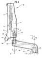
- FIG 1is an illustration of a dialysis machine 10 having a user interface 12 which may be employed in practicing a preferred embodiment of the invention.
- the dialysis machine 10 in the preferred embodimentis a machine suitable for use outside of a traditional dialysis clinic setting, such as the home, nursing home or self-care clinic environment.
- the user interface 12is designed to be easy to use by a person other than a trained health care professional, such as the patient or a family member of the patient.
- the preferred user interface 12comprises a transparent touch screen 14, a display positioned immediately behind the touch screen 14, and a set of three hard keys or buttons 16, 18, 20 positioned below the touch screen 14.
- the touch screen 14 and hard keys 16, 18 and 20are incorporated into a rigid housing 15 that is mounted to the distal end of a moveable arm 30.
- the machine 10has a central computer control system 100 shown in block diagram form in Figure 3 .
- the control system 100is programmed to display information and messages to the patient or user of the machine on a display 14' ( Figure 2 ) immediately behind the touch screen surface 14.
- the control system 100in cooperation with the hard keys 16, 18, 20 and touch screen 14, permits the user to change machine settings and enter information and otherwise control the operation of the machine before, during and after the treatment time.
- the dialysis machine 10 of Figure 1has a water treatment module 23 and a dialysate preparation module 25 contained within the lower compartment 22 of the machine.
- These modules 23, 25play no part in the present invention, and are described in detail in U.S. Patent 5,591,344 to Kenley et al. and assigned to Aksys, Ltd., the assignee of the present invention, and in PCT application publication no. WO 96/25214 .
- These referencesdescribe a preferred dialysis machine suitable for use in the home environment.
- the manner in which the dialysate solutions are prepared and circulated through the dialysate circuitis not particularly important to this invention and is well known in the art, and may be as described in the above-referenced Kenley et al. patent, or as described in the above-referenced Grogan et al. patent, or otherwise.
- the user interface and method of operationis applicable to other types of medical instruments.
- the dialysis machine 10further includes an extracorporeal circuit 24 mounted above the lower cabinet 22.
- the extracorporeal circuitis housed behind a door 27 in an enclosure 26 that is mounted to a turntable 28.
- the turntable 28is moveably mounted to the top of the lower cabinet 22 such that the turntable 28, enclosure 26 and extracorporeal circuit 24 are capable of rotation as a unit relative to the lower cabinet 22 about a vertical axis. The purpose of this rotation is to allow the extracorporeal circuit within the door 27 to be placed directly opposite a patient sitting next to the machine 10.
- the details of the extracorporeal circuit 24 of the machine 10 of Figure 1are also not particularly germane to the present dialysis machine user interface.
- Bloodis removed from the patient and introduced into an arterial line, and pumped by a blood pump to the blood chamber of a dialyzer. Blood-borne toxins and excess water are removed from the blood through the membrane of the dialyzer, and the blood is returned to the patient via a venous line.
- itis conventional in the dialysis art to place an air trap in the venous line.
- a method of using the user interface 12 to adjust the level in the air trapis described in a U.S. patent application of Rodney S. Kenley et al.
- the proximal end of the moveable arm 30may be either attached to the enclosure 26 via a hinge 29 as shown in Figure 1 , to the turntable 28, or to the lower cabinet 22 as shown in Figure 2 , such as to a corner of the upper surface of the lower cabinet, e.g., corner 32.
- the user interface arm 30is connected to the rest of the machine 10 via a hinge 29 or other suitable means such that the arm 30 can rotate about the vertical axis so as to position the user interface in a convenient orientation relative to a patient sitting or reclining next to the machine.
- the user interface 12 of Figure 1is shown in cross section in Figure 2 , along the lines 2-2 of Figure 1 , in an embodiment in which the arm 30 is connected to the upper surface of the machine housing 22 at the corner 32
- a hinge 29connects the proximal end of the arm 30 to the housing 22 and allows the arm 30 to pivot about a vertical axis.
- a second hinge 49 at the distal portion of the arm 30allows the user interface 12 to pivot about a vertical axis.
- a third hinge 47 in the user interface housing 15allows the user interface 12 to tilt about a horizontal axis, i.e., to tilt down towards the patient if the patient is seated or reclining in bed, or up if the patient is standing.
- the extreme lower portion of the user interface housing 15has a lower handle portion 17 below the hard keys 16, 18, 20.
- the handle 17has an extreme lower lip 17A that allows the user to grasp the interface housing 15, and a relatively large surface 17B extending across a substantial portion of the width of the housing that allows the user to push the user interface back, causing the arm 30 to move about the hinge 29, or rotate about the tilt hinge 47.
- the addition of a handle feature as describedallows the user to interact with a specific portion of the user interface 12 away from the touch screen 14, whereby the user is less likely to push the touch screen 14 to move the touch screen about and accidentally operate the controls of the machine 10.
- the lower lip 17A and front surface 17Bthus enable a user to manually manipulate the user interface housing 15 in a manner to cause rotation of the user interface about the housing axis H of Figures 1 and 3 , the arm axis A, and the tilt axis T.
- the front of the user interface housing 15is substantially flat and includes the substantially transparent touch screen 14 per se.
- the display 14' for the touch screenis placed within the housing immediately behind the touch screen 14.
- the hard keys 16, 18, 20are built into the front surface of the housing 15 immediately below the touch screen 14.
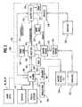
- FIG 3is a block diagram of a computer control system module 100 installed in the lower cabinet 22 of the machine 10 that governs the operation of the machine.
- the use of a central computer control module to control active components of a dialysis machineis well known in the art and described in the above-referenced Kenley et al. and Grogan et al. patents.
- the module 100controls the operation of the touch screen display 14' to display messages and information concerning the status of the machine and treatment.
- the module 100operates the touch screen display 14' to prompt the user to touch the touch screen 14 and the hard keys 16, 18 in the process of changing parameters or inputting information into the computer system 100.
- the touch screen 14interfaces with the patient or other user and is provided for inputting commands or information from the patient into a human interface (HI) board 108 and displaying messages on the display 14' immediately behind the touch screen 14 surface in response to commands from a host Central Processing Unit (CPU) 110 from the HI board 108.
- HIhuman interface
- CPUCentral Processing Unit
- the hard keys 16, 18 and 20are each a pair of physical, electrically isolated switches.
- One switch in each of the hard keys 16, 18, and 20is preferably directly connected, and essentially hard wired, to a backup or safety CPU 116, and the other switch in the hard keys is connected to a host CPU 110.
- the switch for the emergency stop hard key 20 for the host CPU 110is preferably directly connected to host CPU 110 from the HI board 108 over a separate conductor, as shown by the dashed line 101.
- FIG. 3shows the connection between the hard keys 16, 18 and 20 going to the safety CPU 116 via the HI board 108 and conductor 105
- the connection between the hard keys and the safety CPU 116is considered a direct connection since the only function performed by the HI board 108 is debouncing and electrical interfacing the switch signals before they are sent to the Safety CPU 116.
- the connectionis also considered a "direct connection" in the sense the signal path is intentionally designed to not share any circuitry with the Host CPU 110 or the microprocessor on the HI board 108.
- the switch for the Red hard key 20 that is directed to the host CPU 110is directly connected to the host CPU via the HI board 108, which performs debouncing and electrical interfacing, but the circuit does not share any other circuitry on the HI board 108 and the status of the switch is sent to the host CPU over the conductor 101 as described above.
- the switch for the host CPU 110 for the green and blue hard keys 18 and 16, respectively,are subject to debouncing by the microprocessor on the HI board 108, and the status of the switches is sent over the bus 103.
- a set of indicators 104including lights and audio indicators, a buzzer 121, and a speaker 106, alert the patient to abnormal conditions in the machine 10, and provide information as to the status of the modes of operation of the machine.
- the indicators 104receive input signals from the host or safety CPU via the HI board 108.
- the buzzer 121receives input signals from the safety CPU 116.
- audio and visual alarm activitiesare split among the two microprocessors 110, 116 in case one of them fails to work properly.
- the host CPU 110is connected via high speed digital data busses 111 and 113 to a driver board 112 and an analog board 114.
- the host CPU 110comprises a microprocessor and implements a software program governing the operation of the machine stored in a hard disk memory 130 or a read only memory (not shown).
- the hard disk 130stores other operational information, such as the patient's prescription, data from the passive components, and data input from the patient via the touch screen.
- An analog board 114contains analog to digital converters for converting incoming analog signals from the passive sensors in the machine 22 (such as thermistors, pressure sensors and conductivity cells) into digital signals.
- the driver board 112receives commands from the CPU 110 and sends the commands to the valves, pumps, heaters, motors, and other active components of the machine (represented by 120) to cause the components to change their status, e.g., commence or cease operation or change rate, as in the case of a pump, or open and close, as in the case of a valve.
- the signals from the passive components 122 of the systemfor example, the conductivity sensors, pressure transducers, thermistors, etc. provide their inputs to the analog boards 114 and 118.
- the CPU 110 and driver board 112together act as a controller for the active components.
- the analog board 118provides digital information on a bus 117 to the safety CPU 116.
- the safety CPU 116comprises a microprocessor and acts as watchdog of critical system sensors, and provides enable signals to the driver 112 that allow certain driver commands to issue to the active components 120 (such as signals to the valve and air pump to raise or lower the level in the drip chamber in the extracorporeal circuit). These features are described in more detail below as they relate to the changing of machine parameters. Communications between the safety CPU 116 and host CPU 110 are passed on data bus 107.
- the safety CPU 116activates a buzzer or other suitable alarm 121 if certain alarm conditions are present in the machine.
- Both the host and safety CPUs 110 and 116have an associated random access memory 132 and 134, respectively, for use in processing input information from the touch screen 14, for temporary storage of data, and for performing other tasks.
- the host CPU 110 and hard disk 130are based on an off-the-shelf IBM compatible personal computer platform based on an Intel 386 or 486 microprocessor, or the equivalent.
- a similar microprocessor platformmay be used for the safety CPU 116.
- the safety CPU 116also has its own hard disk memory 123. Note that the Safety and Host CPUs 116 and 110 do not share a hard disk, but rather have their own hard disk, for safety and redundancy reasons.
- the host CPU 110preferably has a modem and telephone line interface, a local area network (LAN) gateway card and interface and/or an RS-232 serial port (not shown) for allowing the machine 10 to receive and send messages to remote locations by a suitable communication link.
- LANlocal area network
- RS-232 serial port(not shown) for allowing the machine 10 to receive and send messages to remote locations by a suitable communication link.
- the choice of which type of input/output interfacewill depend on where the machine 10 is installed (e.g., the home (modem), in a hospital (LAN interface), in a nursing home (modem and/or RS-232 and/or LAN).
- Potential entities that may wish to access information from the machineinclude a physician or nurse, the machine manufacturer, a service technician, and a remote monitoring facility such as a central station monitoring a plurality of machines.
- machine status and treatment informationis stored in the hard disk 130 and is accessible to the outside via the modem and host CPU 110 using an interactive program running on the host CPU 110 and at the remote site.
- the host CPU computing platform 110also preferably implements a MicrosoftTM graphical user interface operating system, and also Internet access software to allow messages to be sent to and retrieved from the machine 10 via the Internet.
- Figure 4is an elevational view of the user interface 12 of Figure 1 showing a display on the touch screen 14 that is used prior to the start of the treatment.
- the illustrated displayand preferably all of the displays for the user interface, is organized into discrete zones or portions extending across the width of the display. This organizational scheme assists the user to know where to look on the display for certain functions, icons, and information throughout all of the displays.
- One portionis preferably devoted to displaying instruction and status information to the user.
- Anotheris preferably devoted to displaying primary treatment and machine activities and functions.
- a third portionis preferably used for secondary machine activities and functions.
- the displayhas an upper portion 60 devoted to secondary activities and functions, and includes an icon 62 for a guide, which allows the user to gain information as to the machine when the icon 62 is pressed, a messages icon 64 indicating whether the patient has received new messages (e.g., via the Internet or public telephone network), and a problem report icon 66.
- the problem report icon 66is a means for the machine to notify the patient of problems in a non-treatment mode.
- the screen displayalso has a time and day section 68.
- the middle portion of the display 70conveys status information to the patient, such as when the next treatment time is to begin.
- the portion 70is given a paper pad type of look to reinforce the role played by this portion of the screen.
- the lower portion 72has a set of icons related to primary treatment and machine functions. These icons, when pressed, lead to additional screens that allow the patient to obtain information or enter data as to basic machine and treatment functions. These icons include an icon indicating treatment information 74, a dialysis schedule icon 76, a prescription icon 78 and a machine set-up icon 80.
- the user interface of Figure 4has at least one hard key (a physical button) positioned below the touch screen 14.
- Three hard keysare preferably provided, each with a distinctive visual appearance to assist the user to identify the hard key with a distinct functional attribute: a blue hard key 16, a green hard key 18 and a red hard key 20.
- the hard keys 16, 18 and 20preferably consist of two electrically independent switches, one sending signals to the safety CPU 116 and the other sending signals to the HI board and host CPU 110 as described above.
- the blue hard key 16is connected to the host CPU 110 via the HI board 608, and is hard wired to the safety microprocessor 116.
- the blue hard key 16is solely associated with an entry function. The user presses the blue hard key 16 when the user is finished editing a parameter during the process of changing parametric values for the machine.
- the blue hard key 16is directly hard wired to the safety CPU 116 due to the fact that the safety CPU 116 is involved when parametric values are changed, as discussed below.
- the green hard key 18is a means for the user to confirm parametric value changes and some of the mode transitions of the machine 10.
- the green hard key 18is connected to the host CPU 110 via the user interface software and hardware (i.e., HI board 108) and is hard wired to the safety CPU 116.
- the meaning associated with the pressing of the green hard key 18also depends on the context of the current display and the current state of the machine 10. Due to safety considerations, the safety CPU 116 must have an independent means for determining the user's intention to change parametric values, i.e., independent of the touch screen or the host CPU, hence the green hard key18 is directly connected and essentially hard wired to the safety CPU 116.
- the red hard key 20is a means for the user to issue an "Immediate Stop" command to the machine 10.
- the host and safety CPUs 110 and 116respond by disabling a predetermined group of active components of the machine that leaves the machine in a patient-safe mechanically stopped condition.
- the meaning of the red hard key 20is always the same regardless of the state of the machine 10.
- the red hard key 20is directly connected and essentially hard wired to both the host and safety CPUs. Both microprocessors have the ability to disable the same group of active components, and will, redundant with each other, disable the active components.
- the hard keysare preferably given a different color. Since one of the keys 20 is associated with an emergency stop function it is given a red color.
- the other keys 16 and 18have more latitude in their selection of color, and we prefer to use a green key 18 to be generally identified with a confirmation function.
- the third key 16is identified with an entry function, and is blue in the preferred embodiment.
- theymay be given different shapes, e.g., octagon, square and triangle. Other colors and shapes are of course possible.
- the touch screen 14 and hard keys 16 and 18are used in a process to adjust certain parameters pertinent to the operation of the machine or the dialysis treatment.
- Figure 5is an illustration of the user interface 12 showing a display on the touch screen 14 that can be accessed before or during the dialysis session.
- the touch screen 14displays a message prompting a user to touch an icon 140 if they wish to change the level of the drip chamber in the extracorporeal circuit.
- an illustration of the blood drip chamberis displayed on the screen and the user indicates the current level in the illustration.
- the host CPUdetermines from the indicated level whether the level needs to rise or fall, and by approximately how much, to bring the level back to a predetermined desired level. This process and variations thereto are described in further detail in the above-referenced Kenley et al. patent application.
- the display of Figure 5further includes several icons 142, 144, 146, 148, 150 and 152 that display current treatment settings in numerical form.
- the region 154 below the icons 142, 144, etc.can be used to display other information or to allow the patient to navigate to the previous screen or additional screens, obtain information, or report problems.
- the display of Figure 5requests the patient to press an icon associated with a treatment parameter if they wish to initiate the process of changing the parameter.
- an iconfor example, the treatment length icon 148
- the displayis modified to that shown in Figure 6 .
- Up and down arrowsappear below the icons 142, 144, 146 et al. adjacent to the selected treatment parameter and the treatment parameter icon 148 is highlighted, e.g., made a brighter or a different color from the other icons.
- the usersignifies that the editing is complete by pressing the blue hard key 16. After verification procedures are performed, the user is then prompted to confirm the change by pressing the green hard key 18.
- the above processinvokes operations with both the host and safety CPUs 110 and 116 to provide redundancy and safety features, which will now be described in detail in conjunction with Figures 3 , 5 and 6 .
- a pair up and down arrowssuch as shown in Figure 6 then appear.
- An alternativewould be to prompt the patient to press the green hard key, but this is a less desirable alternative since association of the green hard key 18 with a confirmation function would be diluted:
- a further possibilitywould be to press the activated icon, e.g., icon 144, a second time in response to a prompt.
- the preferred action of pressing the hard key 16 off the touch screen 14initiates storage of the changed parametric value into the working RAM 132 for host CPU 110 ( Figure 3 ).
- a CRC (Cyclical Redundancy Check) valueis calculated by the host CPU 110 for the set of parametric values currently displayed on the screen.
- the CRC checkis calculated by the host CPU 110 only (at this point), and only in response to the pressing of the blue or entry hard key 16.
- the following informationis then sent from the host CPU I 10 to the safety CPU 116 over the bus 107 in response to a pressing of the entry hard key 16: a unique screen identifier associated with the display currently on the touch screen 14, the current values of all the modifiable parameters displayed on the screen, a unique parameter identifier associated with the parameter to be changed, and the calculated CRC value.
- the datais stored in the Safety CPU 116's RAM 134.
- the safety CPU 116then performs a verification routine to determine that the requested change to the parameter is appropriate for the patient and is consistent with the current status of the machine 10 and current display, and prevent any changes that could be harmful to the patient. Specifically, in a preferred embodiment, the safety CPU 116 verifies that the screen displayed could be displayed given the current state of the machine 10. It also verifies that only one parametric value, of all the modifiable parametric values associated with the current screen, has changed. It also verifies that the parameter identified by the host microprocessor 110 is editable on the specified screen. If further verifies that the parameter that the host has identified as being the changed parameter is the same one identified by the safety CPU 116.
- This verificationis done by the Safety CPU 116 using its own copy of the treatment information stored in its hard disk 123 and comparing this information with the information sent from the host CPU 110 to determine which parameter for the screen has changed.
- the safety CPU 116further verifies that the parametric value that changed passes all range, resolution, format and other appropriate validation and safety tests. This is accomplished by comparing the proposed new value with stored values on the hard disk 123 associated with permissible range of values and other validation criteria for the patient.
- the values stored on the hard disk 123may be either modifiable by a doctor's prescription loaded into the hard disk 123 or validation or safety criteria set at the time of machine manufacture.
- the safety CPU 116calculates a CRC on the set of parametric values currently displayed and determines whether the CRC value matches the CRC value calculated by the host CPU 110. It will be appreciated that the above specific verification routine is not the only possible verification routine and can be modified to be more or less stringent for different parameters and states of the machine.
- the safety CPU 116detects an error in the verification routine it notifies the host CPU 110 and treats the failure in a manner to that of a triggered protective system, such as by displaying an error message or activating one of the indicators 104 and/or the buzzer 121.
- the safety CPU 116If the safety CPU 116 does not detect an error, it sends a signal to the host CPU 110 indicating the tests were passed and notifying the host 110 that the host 110 may continue.
- the safety CPU 116transfers back to the host CPU 110 the data stored in RAM 134 that was forwarded from the host 110 (while keeping a copy in RAM 134), and the CRC calculated by the safety CPU. This data is stored in work space in the host CPU's RAM 132.
- the host CPU 110compares the CRC calculated by the safety CPU 116 to the host's CRC value, compares all the parameter values returned by the safety CPU 116 to the values it originally sent, and treats any mismatch in a manner similar to that of a triggered protective system.
- the host CPU 116updates the screen display with the parametric values returned by the safety CPU and stored in RAM 132.
- the host CPU 110then causes the touch screen 14 to display a prompt to the user that they must press the green hard key 18 to confirm the pending change to the displayed parametric value. Note that, up until this point, the data associated with the changed parameter is not yet loaded into the hard disk 130 that contains the program, and thus the machine cannot operate in accordance with the selected parametric value. Rather, a confirmation step must still occur, i.e., a pressing of the green hard key 18 off of the touch screen.
- the host microprocessorcalculates a new CRC file and then writes the RAM 132 copy of the parameters and the CRC to the hard disk 130.
- the safety CPU 116simultaneously performs the same actions with its copy of the CRC and the parameters stored in RAM 134, writing the RAM copy and CRC value to its hard disk 123. Both host and safety CPUs will then reload their sets of parameter and CRC data into their respective RAM and verify with each other that the new CRC value agrees with each other.
- the host CPU 110then removes the "Press the green key to confirm" prompt and enables a screen navigation prompt allowing the user to navigate through other screens. At this point, the user can either navigate off the screen of Figure 6 or select another parameter for editing.
- the changing of the parametric valueis now complete since the parametric value data is loaded into the hard disks of the host and safety CPU.
- the usermay choose to modify another parameter on the same screen after the blue hard key 16 has been pressed.
- the userdoes not have to press the green hard key for every single parameter change. For example, the user may select a new blood flow rate (using icon 142), then press the blue hard key 16 to signify completing of the editing process, select a new fluid removal rate (using icon 146), then press the blue hard key 16, then edit the dialysate temperature (using icon 150), and then press the blue hard key 16.
- the above-described verification routineis performed.
- the displaywill continue to display a "press the Green hard key to confirm" prompt. The user will press the green hard key once to confirm that they intend to change all the parametric values that have been selected.
- the host CPU 110commands the relevant active components of the machine 10 in accordance with the new parametric value.
- the microprocessorsBy also using hard keys or physical switches directly wired to the host and safety CPU to change values, the microprocessors have an independent means for determining whether the user has entered values or intends to confirm the changes. Further, by virtue of connecting the hard keys to both microprocessors, and using the pairs of redundant host and safety memories to check against each other, a failure in either microprocessor or associated memories will be detected, allowing for alarms or other protective action to be initiated while maintaining patient safety,
- the above-described method of using the touch screen and hard keys to change machine or treatment parametersis also applicable to changing operational modes in the machine.
- the display 14may display a prompt indicating that the user should press the green hard key to indicate that they are ready to enter into a prepare access site mode or a dialyze mode.
- Another examplewould be when the user is finishing the dialysis session and indicates to the machine that they are ready to end dialysis and begin a rinseback mode.
- the useris prompted to press a hard key (e.g., the green hard key) to indicate that they wish to confirm that they are ready to start the next mode of operation.
- a verification routingcan be performed by both CPUs to confirm that the machine is in a state where the change is mode is safe for the patient.
- the transition from a clean and rinse mode to a prepare dialysate solution modemay be made without requiring user involvement.
- the current mode of operationis preferably communicated to the patient, such as by displaying a message telling the user what mode the machine is in (e.g., clean and rinse mode) and an illustration communicating how much time remains until the machine has completed the present mode.
- touch screenis intended to mean the combination of the transparent physical surface touched by the user and the display immediately behind the surface touched by the user.
- hard keyas used in the claims, is not intended to be limited to a button or key having two physical switches directed to host and safety CPUs, but rather, unless otherwise stated, is intended to mean simply a manually manipulable physical switch off of the touch screen such as a button operatively connected to a central computer system for the medical instrument.
Landscapes
- Health & Medical Sciences (AREA)
- Engineering & Computer Science (AREA)
- Biomedical Technology (AREA)
- Public Health (AREA)
- General Health & Medical Sciences (AREA)
- Epidemiology (AREA)
- Urology & Nephrology (AREA)
- Medical Informatics (AREA)
- Primary Health Care (AREA)
- Heart & Thoracic Surgery (AREA)
- Nuclear Medicine, Radiotherapy & Molecular Imaging (AREA)
- Business, Economics & Management (AREA)
- General Business, Economics & Management (AREA)
- Emergency Medicine (AREA)
- Surgery (AREA)
- Vascular Medicine (AREA)
- Anesthesiology (AREA)
- Hematology (AREA)
- Life Sciences & Earth Sciences (AREA)
- Animal Behavior & Ethology (AREA)
- Veterinary Medicine (AREA)
- External Artificial Organs (AREA)
- Separation Using Semi-Permeable Membranes (AREA)
Abstract
Description
- This invention relates to the field of medical instruments and their user interfaces, and more particularly to a user interface and control method for a medical instrument such as a dialysis machine.
- Dialysis machine are used for treating patients with inadequate kidney function. Hemodialysis machines typically include, among other things, an extracorporeal blood circuit comprising an arterial line, a blood pump, a dialyzer having a semipermeable membrane and a venous line. Blood is removed from the patient and pumped by the blood pump through the arterial line to the blood compartment of the dialyzer, where toxins and excess water are removed from the patient's blood. A dialysate solution is circulated on the other side of the membrane and carries away the toxins and removed water. The blood is then returned to the patient via the venous line. Peritoneal dialysis machines prepare a dialysate solution which is introduced into the patient's peritoneal cavity.
- Dialysis machines typically have some sort of controls to regulate the operation of the machine. Such controls in the past were a rather unattractive and hard to use set of dials and switches that required trained medical professionals to use properly. More contemporary machines have a single user interface to allow a patient or medical practitioner to interact with the machine and adjust machine operation or treatment parameters, e.g., blood pump rate, dialysate temperature or flow rate, treatment time, heparin pump rate, etc.
- The patent to Grogan et al.,
U.S. No. 5,326,476 , describes a touch screen that is used to control the operation of a hemodialysis machine. The touch screen is connected to a host microprocessor which controls operation of most of the active components of the machine. When the user wishes to change a treatment parameter, the user touches an icon on the touch screen and a key pad with an enter key pops up on the screen. The user enters the new value by touching the numbers on the key pad and pressing the enter button on the key pad. A verify button is then pressed on the touch screen if the user wishes to confirm the change. The patent also briefly describes a method of touching the touch screen to program a time-varying parameter, such as ultrafiltration removal over the course of a dialysis session. - User interfaces that solely depend on a touch screen as a means for entering and confirming parametric values, such as described in the Grogan et al. patent, are vulnerable to failures in the touch screen display. If the touch screen is defective, the computer system may not receive the correct information from the touch screen or interpret the information incorrectly.
- A further dialysis machine having a user interface that solely relies on input via a touch screen for changing parametric values in
US 5,591,344 . This document discloses using host and safety microprocessors for changing the parametric values and for monitoring the system for critical system errors. US 5,247,434 discloses a dialysis machine that requires verification of an altered parametric value selected on a touch screen by pressing of a confirmation button on the touch screen.- According to a first aspect of the present invention there is provided a system for controlling the operation of a dialysis machine as claimed in claim 1.
- The present invention was designed to provide for redundancy and safety verification of parametric value changes independent of the operation of the touch screen, and thereby avoid accidental or unintended changes of parameters in the event of a defect in the touch screen.
- The user interface provides for the combination of a touch screen, and at least one hard key that are separate and apart from the touch screen, whereby both the touch screen and the hard keys have to be pressed to enter and verify a change in a parametric value pertinent to the treatment or the operation of the machine. The computer control system for the machine also uses host and safety backup microprocessors which are responsive to the touch screen and hard keys to perform internal verification and confirmation checking procedures to verify that the change in parametric value requested by the user is proper. These features combine to offer safety benefits, robustness, and ease of use that are believed to be superior to user interfaces known in the prior art.
- The user interface design for a medical instrument disclosed is especially easy to use by a person that is not a technically trained medical professional, i.e., by the patient or a member of the patient's family.
- A system for controlling the operation of a dialysis machine is provided comprising in combination a user interface and a central computer control system. The user interface comprises a touch screen that displays messages and information as to the machine status to a user, and permits the user to touch the touch screen to select parametric values pertinent to operation of the machine. The user interface further includes at least one hard key off of the touch screen. The touch screen prompts the user to press the hard key to signify that the selection of the parametric value by the user has been completed.
- The central computer control system controls operation of the machine and is responsive to the touch screen and the hard key. The control system comprises a host central processing unit and a safety central processing unit (both comprising microprocessors) operatively connected to each other so as to enable an exchange of information related to the selected parametric value.
- When the user presses the hard key to indicate that the selection process is complete, this action causes the host and safety microprocessors to undergo a verification routine whereby the selected parametric value is checked for appropriateness for a patient connected to the machine so as to prevent changes to the parameter potentially harmful to the patient. If the verification routine results in a positive result, the process of changing the parameter may move forward.
- In a preferred embodiment, the hard key is directly wired to the safety central processing unit. The user interface also preferably comprises first, second and third hard keys, each of them directly wired to the safety central processing unit. The hard keys are preferably given a distinctive appearance so as to enable the user to identify each hard key with a distinct functional attribute, eg., stop, confirm, or entry.
- According to another aspect of the present invention there is provided a method of controlling a dialysis machine as claimed in
claim 15. The dialysis machine has a central computer control system and a user interface having a touch screen enabling a patient, by touching the touch screen, to select parametric values and accomplish entry of the selected parametric values in a process of changing a parametric value pertinent to operation of the machine or to a dialysis treatment of a patient connected to the machine. The method comprises providing the user interface with at least one hard key and connecting the hard key directly to the central computer control system. After the user has selected the parametric value and (a) entered the parametric value selected by touching the touch screen, the user is prompted to press the hard key to confirm the entry of the parametric value. A failure in the touch screen to respond to touching of the touch screen to confirm parametric value changes may be avoided. - In one embodiment of the invention, the central computer control system for the machine preferably includes host and safety CPUs; each comprising a microprocessor. The host and safety microprocessors each have a first memory such as a random access memory (RAM) and a second memory, such as a hard disk, storing machine operation instructions and treatment prescriptions.
- According to a further apect of the present invention there is provided a dialysis machine comprising user interface and screen display apparatus as claimed in
claim 22. - A method is further disclosed for using the touch screen, two hard keys, the first and second memories and host and safety microprocessors to change parameters to provide enhanced redundancy and safety capabilities and avoid single point failures in the touch screen, host microprocessor, or host memories. The method comprises the steps of:
- a) touching the touch screen to select a parametric value;
- b) pressing the first hard key to enter the selected parametric value, the computer system responsively storing the selected parametric value in the first memory is associated with the host microprocessor;
- c) in response to pressing the first hard key, transmitting data associated with the selected value from the host microprocessor to the safety microprocessor and implementing a verification routine in the safety microprocessor. The safety microprocessor checks the parametric value for appropriateness for a patient connected to the machine so as to prevent changes from being implemented to the parameter potentially harmful to the patent.
- d) If the verification routine has a positive result, the safety sends a signal back to the host microprocessor granting approval to the change and stores the changed parameter in its first memory. The touch screen then displays a message prompting the user to press the second hard key to confirm the change selected in step a).
- e) If the user presses the second hard key to confirm the change, the host and safety microprocessors stores the new value in their respective second memories. The host and safety microprocessors then conduct a checking procedure to insure that the new value has been correctly stored in their second memories.
- These and many other features of the invention will be more apparent from the following detailed description of preferred embodiments of the invention.
- Various preferred embodiments of the present invention will now be described by way of example only and with reference to the accompanying drawings, in which:
Figure 1 is an illustration of a dialysis machine having a user interface in accordance with a preferred embodiment of the invention.Figure 2 is a cross-sectional view of the user interface in an embodiment in which the arm connecting the user interface to the machine is attached to the lower cabinet of the machine;Figure 3 is a block diagram of a control system governing the operation of the machine ofFigure 1 .Figure 4 is an elevational view of the user interface for the machine ofFigure 1 , showing the general organization of the screen into discrete regions associated with different general functions.Figure 5 is an illustration of the user interface ofFigure 4 , with the touch screen displaying a dialysis prescription during a treatment session, the display requesting the patient to press an icon associated with a treatment parameter if they wish to change a parameter.Figure 6 is an illustration of the user interface ofFigure 1 after the user has pressed the icon shown inFigure 5 , showing up and down arrows that permit the user to select a different value for the treatment parameter.Figure 1 is an illustration of adialysis machine 10 having auser interface 12 which may be employed in practicing a preferred embodiment of the invention. Thedialysis machine 10 in the preferred embodiment is a machine suitable for use outside of a traditional dialysis clinic setting, such as the home, nursing home or self-care clinic environment. Theuser interface 12 is designed to be easy to use by a person other than a trained health care professional, such as the patient or a family member of the patient.- The preferred
user interface 12 comprises atransparent touch screen 14, a display positioned immediately behind thetouch screen 14, and a set of three hard keys orbuttons touch screen 14. Thetouch screen 14 andhard keys rigid housing 15 that is mounted to the distal end of amoveable arm 30. - The
machine 10 has a centralcomputer control system 100 shown in block diagram form inFigure 3 . Thecontrol system 100 is programmed to display information and messages to the patient or user of the machine on adisplay 14' (Figure 2 ) immediately behind thetouch screen surface 14. Thecontrol system 100, in cooperation with thehard keys touch screen 14, permits the user to change machine settings and enter information and otherwise control the operation of the machine before, during and after the treatment time. - The
dialysis machine 10 ofFigure 1 has awater treatment module 23 and adialysate preparation module 25 contained within thelower compartment 22 of the machine. Thesemodules U.S. Patent 5,591,344 to Kenley et al. and assigned to Aksys, Ltd., the assignee of the present invention, and inPCT application publication no. WO 96/25214 - The
dialysis machine 10 further includes anextracorporeal circuit 24 mounted above thelower cabinet 22. The extracorporeal circuit is housed behind adoor 27 in anenclosure 26 that is mounted to aturntable 28. Theturntable 28 is moveably mounted to the top of thelower cabinet 22 such that theturntable 28,enclosure 26 andextracorporeal circuit 24 are capable of rotation as a unit relative to thelower cabinet 22 about a vertical axis. The purpose of this rotation is to allow the extracorporeal circuit within thedoor 27 to be placed directly opposite a patient sitting next to themachine 10. - The details of the
extracorporeal circuit 24 of themachine 10 ofFigure 1 are also not particularly germane to the present dialysis machine user interface. Blood is removed from the patient and introduced into an arterial line, and pumped by a blood pump to the blood chamber of a dialyzer. Blood-borne toxins and excess water are removed from the blood through the membrane of the dialyzer, and the blood is returned to the patient via a venous line. To prevent air from being introduced into the blood being returned to the patient, it is conventional in the dialysis art to place an air trap in the venous line. A method of using theuser interface 12 to adjust the level in the air trap is described in a U.S. patent application of Rodney S. Kenley et al. Details of the extracorporeal circuit illustrated inFigure 1 can be found in the published PCT application of Kenley et al., publication no.WO 96/25214 U.S. Patent No. 5,591,344 . - The proximal end of the
moveable arm 30 may be either attached to theenclosure 26 via ahinge 29 as shown inFigure 1 , to theturntable 28, or to thelower cabinet 22 as shown inFigure 2 , such as to a corner of the upper surface of the lower cabinet, e.g.,corner 32. Preferably, theuser interface arm 30 is connected to the rest of themachine 10 via ahinge 29 or other suitable means such that thearm 30 can rotate about the vertical axis so as to position the user interface in a convenient orientation relative to a patient sitting or reclining next to the machine. - The
user interface 12 ofFigure 1 is shown in cross section inFigure 2 , along the lines 2-2 ofFigure 1 , in an embodiment in which thearm 30 is connected to the upper surface of themachine housing 22 at the corner 32 Ahinge 29 connects the proximal end of thearm 30 to thehousing 22 and allows thearm 30 to pivot about a vertical axis. Asecond hinge 49 at the distal portion of thearm 30 allows theuser interface 12 to pivot about a vertical axis. Athird hinge 47 in theuser interface housing 15 allows theuser interface 12 to tilt about a horizontal axis, i.e., to tilt down towards the patient if the patient is seated or reclining in bed, or up if the patient is standing. - The extreme lower portion of the
user interface housing 15 has alower handle portion 17 below thehard keys handle 17 has an extremelower lip 17A that allows the user to grasp theinterface housing 15, and a relativelylarge surface 17B extending across a substantial portion of the width of the housing that allows the user to push the user interface back, causing thearm 30 to move about thehinge 29, or rotate about thetilt hinge 47. The addition of a handle feature as described allows the user to interact with a specific portion of theuser interface 12 away from thetouch screen 14, whereby the user is less likely to push thetouch screen 14 to move the touch screen about and accidentally operate the controls of themachine 10. Thelower lip 17A andfront surface 17B thus enable a user to manually manipulate theuser interface housing 15 in a manner to cause rotation of the user interface about the housing axis H ofFigures 1 and3 , the arm axis A, and the tilt axis T. - The front of the
user interface housing 15 is substantially flat and includes the substantiallytransparent touch screen 14 per se. Thedisplay 14' for the touch screen is placed within the housing immediately behind thetouch screen 14. Thehard keys housing 15 immediately below thetouch screen 14. Figure 3 is a block diagram of a computercontrol system module 100 installed in thelower cabinet 22 of themachine 10 that governs the operation of the machine. The use of a central computer control module to control active components of a dialysis machine is well known in the art and described in the above-referenced Kenley et al. and Grogan et al. patents. Themodule 100 controls the operation of thetouch screen display 14' to display messages and information concerning the status of the machine and treatment. Themodule 100 operates thetouch screen display 14' to prompt the user to touch thetouch screen 14 and thehard keys computer system 100.- The
touch screen 14 interfaces with the patient or other user and is provided for inputting commands or information from the patient into a human interface (HI)board 108 and displaying messages on thedisplay 14' immediately behind thetouch screen 14 surface in response to commands from a host Central Processing Unit (CPU) 110 from theHI board 108. - The
hard keys hard keys safety CPU 116, and the other switch in the hard keys is connected to ahost CPU 110. The switch for the emergency stop hard key 20 for thehost CPU 110 is preferably directly connected to hostCPU 110 from theHI board 108 over a separate conductor, as shown by the dashedline 101. - While
FIG. 3 shows the connection between thehard keys safety CPU 116 via theHI board 108 andconductor 105, the connection between the hard keys and thesafety CPU 116 is considered a direct connection since the only function performed by theHI board 108 is debouncing and electrical interfacing the switch signals before they are sent to theSafety CPU 116. The connection is also considered a "direct connection" in the sense the signal path is intentionally designed to not share any circuitry with theHost CPU 110 or the microprocessor on theHI board 108. - The switch for the Red hard key 20 that is directed to the
host CPU 110 is directly connected to the host CPU via theHI board 108, which performs debouncing and electrical interfacing, but the circuit does not share any other circuitry on theHI board 108 and the status of the switch is sent to the host CPU over theconductor 101 as described above. The switch for thehost CPU 110 for the green and bluehard keys HI board 108, and the status of the switches is sent over thebus 103. - A set of
indicators 104, including lights and audio indicators, abuzzer 121, and aspeaker 106, alert the patient to abnormal conditions in themachine 10, and provide information as to the status of the modes of operation of the machine. Theindicators 104 receive input signals from the host or safety CPU via theHI board 108. Thebuzzer 121 receives input signals from thesafety CPU 116. Thus, audio and visual alarm activities are split among the twomicroprocessors - The
host CPU 110 is connected via high speed digital data busses 111 and 113 to adriver board 112 and ananalog board 114. Thehost CPU 110 comprises a microprocessor and implements a software program governing the operation of the machine stored in ahard disk memory 130 or a read only memory (not shown). Thehard disk 130 stores other operational information, such as the patient's prescription, data from the passive components, and data input from the patient via the touch screen. Ananalog board 114 contains analog to digital converters for converting incoming analog signals from the passive sensors in the machine 22 (such as thermistors, pressure sensors and conductivity cells) into digital signals. Thedriver board 112 receives commands from theCPU 110 and sends the commands to the valves, pumps, heaters, motors, and other active components of the machine (represented by 120) to cause the components to change their status, e.g., commence or cease operation or change rate, as in the case of a pump, or open and close, as in the case of a valve. The signals from thepassive components 122 of the system, for example, the conductivity sensors, pressure transducers, thermistors, etc. provide their inputs to theanalog boards CPU 110 anddriver board 112 together act as a controller for the active components. - The
analog board 118 provides digital information on abus 117 to thesafety CPU 116. Thesafety CPU 116 comprises a microprocessor and acts as watchdog of critical system sensors, and provides enable signals to thedriver 112 that allow certain driver commands to issue to the active components 120 (such as signals to the valve and air pump to raise or lower the level in the drip chamber in the extracorporeal circuit). These features are described in more detail below as they relate to the changing of machine parameters. Communications between thesafety CPU 116 andhost CPU 110 are passed ondata bus 107. Thesafety CPU 116 activates a buzzer or othersuitable alarm 121 if certain alarm conditions are present in the machine. - Both the host and
safety CPUs random access memory touch screen 14, for temporary storage of data, and for performing other tasks. In a preferred embodiment, thehost CPU 110 andhard disk 130 are based on an off-the-shelf IBM compatible personal computer platform based on an Intel 386 or 486 microprocessor, or the equivalent. A similar microprocessor platform may be used for thesafety CPU 116. Of course, other types of microprocessor platforms may be used. Thesafety CPU 116 also has its ownhard disk memory 123. Note that the Safety andHost CPUs - The
host CPU 110 preferably has a modem and telephone line interface, a local area network (LAN) gateway card and interface and/or an RS-232 serial port (not shown) for allowing themachine 10 to receive and send messages to remote locations by a suitable communication link. The choice of which type of input/output interface will depend on where themachine 10 is installed (e.g., the home (modem), in a hospital (LAN interface), in a nursing home (modem and/or RS-232 and/or LAN). Potential entities that may wish to access information from the machine include a physician or nurse, the machine manufacturer, a service technician, and a remote monitoring facility such as a central station monitoring a plurality of machines. Preferably, machine status and treatment information is stored in thehard disk 130 and is accessible to the outside via the modem andhost CPU 110 using an interactive program running on thehost CPU 110 and at the remote site. The hostCPU computing platform 110 also preferably implements a Microsoft™ graphical user interface operating system, and also Internet access software to allow messages to be sent to and retrieved from themachine 10 via the Internet. Figure 4 is an elevational view of theuser interface 12 ofFigure 1 showing a display on thetouch screen 14 that is used prior to the start of the treatment. The illustrated display, and preferably all of the displays for the user interface, is organized into discrete zones or portions extending across the width of the display. This organizational scheme assists the user to know where to look on the display for certain functions, icons, and information throughout all of the displays. One portion is preferably devoted to displaying instruction and status information to the user. Another is preferably devoted to displaying primary treatment and machine activities and functions. A third portion is preferably used for secondary machine activities and functions.- An embodiment of this general organizational scheme is shown in
Figure 4 . The display has anupper portion 60 devoted to secondary activities and functions, and includes anicon 62 for a guide, which allows the user to gain information as to the machine when theicon 62 is pressed, amessages icon 64 indicating whether the patient has received new messages (e.g., via the Internet or public telephone network), and aproblem report icon 66. Theproblem report icon 66 is a means for the machine to notify the patient of problems in a non-treatment mode. The screen display also has a time andday section 68. - The middle portion of the
display 70 conveys status information to the patient, such as when the next treatment time is to begin. Theportion 70 is given a paper pad type of look to reinforce the role played by this portion of the screen. - The
lower portion 72 has a set of icons related to primary treatment and machine functions. These icons, when pressed, lead to additional screens that allow the patient to obtain information or enter data as to basic machine and treatment functions. These icons include an icon indicating treatment information 74, adialysis schedule icon 76, aprescription icon 78 and a machine set-upicon 80. - When the user wishes to enter information into the machine from any of these menus, the user presses the
touch screen 14 to navigate through various screen displays until they arrive at the appropriate screen for the action they wish to take. - As noted above, the user interface of
Figure 4 has at least one hard key (a physical button) positioned below thetouch screen 14. Three hard keys are preferably provided, each with a distinctive visual appearance to assist the user to identify the hard key with a distinct functional attribute: a bluehard key 16, a green hard key 18 and a redhard key 20. Thehard keys safety CPU 116 and the other sending signals to the HI board andhost CPU 110 as described above. - The blue
hard key 16 is connected to thehost CPU 110 via the HI board 608, and is hard wired to thesafety microprocessor 116. The bluehard key 16 is solely associated with an entry function. The user presses the bluehard key 16 when the user is finished editing a parameter during the process of changing parametric values for the machine. The bluehard key 16 is directly hard wired to thesafety CPU 116 due to the fact that thesafety CPU 116 is involved when parametric values are changed, as discussed below. - The green hard key 18 is a means for the user to confirm parametric value changes and some of the mode transitions of the
machine 10. The green hard key 18 is connected to thehost CPU 110 via the user interface software and hardware (i.e., HI board 108) and is hard wired to thesafety CPU 116. The meaning associated with the pressing of the green hard key 18 also depends on the context of the current display and the current state of themachine 10. Due to safety considerations, thesafety CPU 116 must have an independent means for determining the user's intention to change parametric values, i.e., independent of the touch screen or the host CPU, hence the green hard key18 is directly connected and essentially hard wired to thesafety CPU 116. - The red hard key 20 is a means for the user to issue an "Immediate Stop" command to the
machine 10. The host andsafety CPUs machine 10. Unlike the blue and green hard keys, the red hard key 20 is directly connected and essentially hard wired to both the host and safety CPUs. Both microprocessors have the ability to disable the same group of active components, and will, redundant with each other, disable the active components. - As noted above, in order to assist the user to become familiar with the functions provided by the hard keys, they are preferably given a different color. Since one of the
keys 20 is associated with an emergency stop function it is given a red color. Theother keys green key 18 to be generally identified with a confirmation function. The third key 16 is identified with an entry function, and is blue in the preferred embodiment. To assist further in reinforcing their different functions, they may be given different shapes, e.g., octagon, square and triangle. Other colors and shapes are of course possible. - In accordance with the preferred embodiment, the
touch screen 14 andhard keys Figure 5 is an illustration of theuser interface 12 showing a display on thetouch screen 14 that can be accessed before or during the dialysis session. Thetouch screen 14 displays a message prompting a user to touch anicon 140 if they wish to change the level of the drip chamber in the extracorporeal circuit. When thisicon 140 is pressed, an illustration of the blood drip chamber is displayed on the screen and the user indicates the current level in the illustration. The host CPU determines from the indicated level whether the level needs to rise or fall, and by approximately how much, to bring the level back to a predetermined desired level. This process and variations thereto are described in further detail in the above-referenced Kenley et al. patent application. - The display of
Figure 5 further includesseveral icons region 154 below theicons - The display of
Figure 5 requests the patient to press an icon associated with a treatment parameter if they wish to initiate the process of changing the parameter. When the user presses an icon, for example, thetreatment length icon 148, the display is modified to that shown inFigure 6 . Up and down arrows appear below theicons treatment parameter icon 148 is highlighted, e.g., made a brighter or a different color from the other icons. The user presses the up or downbuttons hard key 16. After verification procedures are performed, the user is then prompted to confirm the change by pressing the green hard key 18. - In the preferred embodiment of the invention, the above process invokes operations with both the host and
safety CPUs Figures 3 ,5 and6 . - The user touches one of
icons Figure 6 then appear. The user presses the up and down icons to select the new parametric value. In response to a prompt, the user indicates that the editing process is complete by pressing the bluehard key 16. An alternative would be to prompt the patient to press the green hard key, but this is a less desirable alternative since association of the green hard key 18 with a confirmation function would be diluted: A further possibility would be to press the activated icon, e.g.,icon 144, a second time in response to a prompt. The preferred action of pressing thehard key 16 off thetouch screen 14 initiates storage of the changed parametric value into the workingRAM 132 for host CPU 110 (Figure 3 ). A CRC (Cyclical Redundancy Check) value is calculated by thehost CPU 110 for the set of parametric values currently displayed on the screen. The CRC check is calculated by thehost CPU 110 only (at this point), and only in response to the pressing of the blue or entry hard key 16. - The following information is then sent from the host CPU I 10 to the
safety CPU 116 over thebus 107 in response to a pressing of the entry hard key 16: a unique screen identifier associated with the display currently on thetouch screen 14, the current values of all the modifiable parameters displayed on the screen, a unique parameter identifier associated with the parameter to be changed, and the calculated CRC value. The data is stored in theSafety CPU 116'sRAM 134. - The
safety CPU 116 then performs a verification routine to determine that the requested change to the parameter is appropriate for the patient and is consistent with the current status of themachine 10 and current display, and prevent any changes that could be harmful to the patient. Specifically, in a preferred embodiment, thesafety CPU 116 verifies that the screen displayed could be displayed given the current state of themachine 10. It also verifies that only one parametric value, of all the modifiable parametric values associated with the current screen, has changed. It also verifies that the parameter identified by thehost microprocessor 110 is editable on the specified screen. If further verifies that the parameter that the host has identified as being the changed parameter is the same one identified by thesafety CPU 116. This verification is done by theSafety CPU 116 using its own copy of the treatment information stored in itshard disk 123 and comparing this information with the information sent from thehost CPU 110 to determine which parameter for the screen has changed. Thesafety CPU 116 further verifies that the parametric value that changed passes all range, resolution, format and other appropriate validation and safety tests. This is accomplished by comparing the proposed new value with stored values on thehard disk 123 associated with permissible range of values and other validation criteria for the patient. The values stored on thehard disk 123 may be either modifiable by a doctor's prescription loaded into thehard disk 123 or validation or safety criteria set at the time of machine manufacture. Finally, thesafety CPU 116 calculates a CRC on the set of parametric values currently displayed and determines whether the CRC value matches the CRC value calculated by thehost CPU 110. It will be appreciated that the above specific verification routine is not the only possible verification routine and can be modified to be more or less stringent for different parameters and states of the machine. - If the
safety CPU 116 detects an error in the verification routine it notifies thehost CPU 110 and treats the failure in a manner to that of a triggered protective system, such as by displaying an error message or activating one of theindicators 104 and/or thebuzzer 121. - If the
safety CPU 116 does not detect an error, it sends a signal to thehost CPU 110 indicating the tests were passed and notifying thehost 110 that thehost 110 may continue. Thesafety CPU 116 transfers back to thehost CPU 110 the data stored inRAM 134 that was forwarded from the host 110 (while keeping a copy in RAM 134), and the CRC calculated by the safety CPU. This data is stored in work space in the host CPU'sRAM 132. - The
host CPU 110 then compares the CRC calculated by thesafety CPU 116 to the host's CRC value, compares all the parameter values returned by thesafety CPU 116 to the values it originally sent, and treats any mismatch in a manner similar to that of a triggered protective system. - If the comparison is valid, then the
host CPU 116 updates the screen display with the parametric values returned by the safety CPU and stored inRAM 132. Thehost CPU 110 then causes thetouch screen 14 to display a prompt to the user that they must press the green hard key 18 to confirm the pending change to the displayed parametric value. Note that, up until this point, the data associated with the changed parameter is not yet loaded into thehard disk 130 that contains the program, and thus the machine cannot operate in accordance with the selected parametric value. Rather, a confirmation step must still occur, i.e., a pressing of the green hard key 18 off of the touch screen. - When the user presses the green hard key 18 to confirm the change, the host microprocessor calculates a new CRC file and then writes the
RAM 132 copy of the parameters and the CRC to thehard disk 130. Thesafety CPU 116 simultaneously performs the same actions with its copy of the CRC and the parameters stored inRAM 134, writing the RAM copy and CRC value to itshard disk 123. Both host and safety CPUs will then reload their sets of parameter and CRC data into their respective RAM and verify with each other that the new CRC value agrees with each other. Thehost CPU 110 then removes the "Press the green key to confirm" prompt and enables a screen navigation prompt allowing the user to navigate through other screens. At this point, the user can either navigate off the screen ofFigure 6 or select another parameter for editing. The changing of the parametric value is now complete since the parametric value data is loaded into the hard disks of the host and safety CPU. - While the above discussion has assumed that the user only modifies one of the several parameters from the display of
Figure 6 , the user may choose to modify another parameter on the same screen after the bluehard key 16 has been pressed. The user does not have to press the green hard key for every single parameter change. For example, the user may select a new blood flow rate (using icon 142), then press the bluehard key 16 to signify completing of the editing process, select a new fluid removal rate (using icon 146), then press the bluehard key 16, then edit the dialysate temperature (using icon 150), and then press the bluehard key 16. After each pressing of the bluehard key 16, the above-described verification routine is performed. If the verification routine results in a positive result for each pressing of the blue hard key, the display will continue to display a "press the Green hard key to confirm" prompt. The user will press the green hard key once to confirm that they intend to change all the parametric values that have been selected. - Since the new updated parametric value(s) are now entered into the
hard disk memory 130, thehost CPU 110 commands the relevant active components of themachine 10 in accordance with the new parametric value. - This use of the hard keys in the process of changing parametric values is considered to be distinctly different and an improvement from merely touching the touch screen to enter or change values, since the touch screen can be prone to failures. Failures in a touch screen to properly respond to a touching of the surface can arise in a variety of ways, such from mechanical failures due to repeated use over a prolonged period of time, the screen surface material taking on a depression or set in a particular area from repeated use, electro-static shock causing the grid to fail in particular area, high electromagnetic fields causing the contacts to touch, cleaning agents leaking around the periphery of the screen, and so on. By also using hard keys or physical switches directly wired to the host and safety CPU to change values, the microprocessors have an independent means for determining whether the user has entered values or intends to confirm the changes. Further, by virtue of connecting the hard keys to both microprocessors, and using the pairs of redundant host and safety memories to check against each other, a failure in either microprocessor or associated memories will be detected, allowing for alarms or other protective action to be initiated while maintaining patient safety,
- The above-described method of using the touch screen and hard keys to change machine or treatment parameters is also applicable to changing operational modes in the machine. For example, if the
machine 10 is in a prepare dialysate solution mode, thedisplay 14 may display a prompt indicating that the user should press the green hard key to indicate that they are ready to enter into a prepare access site mode or a dialyze mode. Another example would be when the user is finishing the dialysis session and indicates to the machine that they are ready to end dialysis and begin a rinseback mode. The user is prompted to press a hard key (e.g., the green hard key) to indicate that they wish to confirm that they are ready to start the next mode of operation. Further, by virtue of the connection of the hard keys to both the host and safety CPUs, a verification routing can be performed by both CPUs to confirm that the machine is in a state where the change is mode is safe for the patient. - For some mode changes, it is presently contemplated that little or no user interaction with the machine is necessary. For example, the transition from a clean and rinse mode to a prepare dialysate solution mode may be made without requiring user involvement. However, the current mode of operation is preferably communicated to the patient, such as by displaying a message telling the user what mode the machine is in (e.g., clean and rinse mode) and an illustration communicating how much time remains until the machine has completed the present mode.
- The term "touch screen" is intended to mean the combination of the transparent physical surface touched by the user and the display immediately behind the surface touched by the user. The term "hard key", as used in the claims, is not intended to be limited to a button or key having two physical switches directed to host and safety CPUs, but rather, unless otherwise stated, is intended to mean simply a manually manipulable physical switch off of the touch screen such as a button operatively connected to a central computer system for the medical instrument.
Claims (29)
- A system for controlling the operation of a dialysis machine (10), comprising, in combination:a user interface (12) comprising:(1) a touch screen (14) displaying messages and information as to said machine (10) to a user and permitting said user to touch said touch screen (14) to select at least one parametric value pertinent to operation of said machine (10) or pertinent to a treatment by said machine (10); and(2) at least one hard key (16) off of said touch screen (14), said touch screen (14) prompting said user to press said hard key (16; ) to signify that the selection of said at least one parametric value by said user has been completed; anda control system (100) within said machine (10) for controlling operation of said machine (10) and responsive to said touch screen (14) and said at least one hard key (16), said control system (100) comprising a host microprocessor (110) and a safety microprocessor (116) operatively connected to each other so as to enable an exchange of information related to said at least one selected parametric value,wherein pressing of said hard key (16) causes said host (110) and safety (116) microprocessors to undergo a verification routine whereby said selected parametric value is checked for appropriateness for a patient connected to said machine (10) so as to prevent changes to said parameter potentially harmful to said patient.
- A system as claimed in claim 1, wherein said hard key (16) is directly wired to said safety microprocessor (116) so as to permit said safety microprocessor (116) to respond to a pressing of said hard key (16).
- A system as claimed in claim 1 or 2, wherein said user interface (12) comprises first (20), second (16) and third (18) hard keys, said first hard key (20) associated with an emergency stop function for said machine (10) said second hard key (16) associated with an entry function for entering said selected at least one parametric value, and said third hard key (18) associated with a confirmation function for confirming that the at least one entered parametric value is intended by said user of said machine (10), said touch screen (14) prompting said user to touch either said second hard key (16) or said third hard key (18) after said user has touched said touch screen (14) to select said at least one parametric value.
- A system as claimed in claim 1 or 2, wherein said user interface (12) comprises at least first (20) and second (16) hard keys, said first (20) hard key having a first color and said second (16) of said hard keys having a second colour distinctly different from said first color.
- A system as claimed in claim 4, wherein said user interface comprises a third hard key (18) having a third color, wherein said first color comprises red, and said third color comprises green.
- A system as claimed in claim 1 or 2, wherein said user interface (12) comprises first (20), second (16) and third (18) hard keys, each of said first (20), second (16) and third (18) hard keys hard wired to said safety microprocessor.
- A system as claimed in claim 1 or 2, wherein said user is prompted to press a second hard key (16) to confirm that said selected at least one parametric value is intended by said user.
- A system as claimed in claim 1, wherein said dialysis machine (10) has an enclosure (26) containing hydraulic circuitry (24) for said machine (10) comprising:an arm (30) having a proximal end connected to said machine and a free distal end portion;a display assembly connected to said free distal end portion of said arm (30), said display comprising said touch screen (14),wherein said proximal end of said arm (30) is mounted to said machine (10) in a manner permitting said arm (30) to rotate about at least one axis relative to said machine (10) to thereby position said display at the distal portion thereof in a multitude of different positions relative to said machine (10); andwherein said display is connected to said free distal end portion of said arm (30) by a hinge means (47,49) for permitting a user of said machine to rotate said display about at least one axis relative to said arm.
- A system as claimed in claim 8, further comprising a second hinge means (47) connected to said display for permitting said display to be rotated relative to said arm (30) about a horizontal axis.
- A system as claimed in claim 8 or 9, wherein said at least one hard key (16) is mounted adjacent to said touch screen (14) in said display assembly.
- A system as claimed in claim 10, wherein said display assembly further comprises three hard keys (16, 18, 20) mounted adjacent to said touch screen (14).
- A system as claimed in claim 11, wherein said three hard keys (16, 18, 20) are each a distinctly different color.
- A system as claimed in claim 11, wherein said three hard keys (16, 18, 20) are each a distinctly different color and wherein at least one (20) of said hard keys (16,18,20) has a distinctly different shape from the other two hard keys (16, 18).
- A system as claimed in claim 8, further comprising a handle portion (17) below said touch screen (14) comprising a lower lip (17A) enabling a user to grasp a user interface housing (15) and a front surface extending across a portion of the width of said housing (15), said lower lip (17A) and said front surface enabling a user to manually manipulate said user interface housing (15) in a manner to cause rotation of said user interface (12) about said at least one axis relative to said machine (10) and said at least one axis relative to said arm (30).
- A method of controlling a dialysis machine (10) having a user interface (12) and a central computer system (100) to control the operation of said dialysis machine (10), said user interface (12) having a touch screen (14) enabling a patient, by touching the touch screen (14), to elect parametric values and accomplish entry of said selected parametric values in a process of changing a parametric value pertinent to operation of said machine (10) or pertinent to a dialysis treatment of a patient connected to said machine, the method comprising:providing said user interface with at least one hard key (16;18);connecting said hard key (16;18) to said central computer system (100); andafter said user has selected said parametric value and entered said selected parametric value by touching the touch screen (14), prompting said user of said machine (10) to press said hard key (16:18) to confirm the entry of said parametric value, so that a failure in said touch screen (14) to respond to touching of the touch screen (14) to confirm parametric value changes may be avoided.
- A method as claimed in claim 15, further comprising:providing said central computer system (100) with a host microprocessor (110) and a safety microprocessor (116) and connecting said hard key (16;18) to both said host microprocessor (110) and said safety microprocessor (116), with said hard key (16;18) directly wired to said safety microprocessor (116).
- A method as claimed in claim 15, further comprising:providing said user interface (12) with first (20), second (16) and third (18) hard keys, said first hard key (20) associated with an emergency stop function for said machine (10), said second hard key (16) associated with entry function for entering said selected parametric value, and said third hard key (18) associated with a confirmation function for confirming that the entered parametric value is intended by said user of said machine (10), said touch screen (14) prompting said user to touch said second hard key (16) after said user has touched said touch screen (14) to select said machine operation parameter.
- A method as claimed in claim 15, wherein said user interface (12) comprises a first hard key (16) and a second hard key (18), and wherein said central computer system (100) comprises a control system responsive to said first (16) and second (18) hard keys, said control system comprising a host microprocessor (110) and a safety microprocessor (116), said host (110) and safety (116) microprocessors each having a first memory (132, 134) and a second memory (130, 123) storing machine operation instructions, the method further comprising the steps of:(a) displaying on said touch screen (14) a display permitting a user to touch said touch screen (14) to select a parametric value associated with a parameter pertinent to operation of said machine (10) or pertinent to a dialysis treatment conducted by said machine (10);(b) pressing said first hard key (16) to enter said parametric value, said control system (100) responsively storing said selected parametric value in said first memory (132) associated with said host microprocessor (110);in response to pressing said first hard key (16), transmitting data associated with said parametric value and said parameter from said host microprocessor (110) to said safety microprocessor (116) and implementing a verification routine in said safety microprocessor (116), wherein said parametric value is checked for appropriateness for a patient connected to said machine (10) so as to prevent changes to said parameter potentially harmful to said patient;
if said verification routine has a positive result, prompting said user to press said second hard key (18) to confirm the change selected in step a) and responsively pressing said second hard key (18) and storing said data associated with said parametric value in said first memory (134) associated with said safety microprocessor (116);
storing in said second memory (130, 123) associated with said host (110) and safety (116) microprocessors said data associated with said parametric value; and
checking, with said host (110) and safety (116) microprocessors, the contents of their respective first (132, 134) and second (130, 123) memories against each other to insure that said data associated with said parametric value has in their respective first (132, 134) and second (130, 123) memories is the same. - A method as claimed in claim 18, wherein said second memory (130) associated with said host microprocessor (110) comprises a hard disk storing a prescription for patient using said machine (10).
- A method as claimed in claim 18, wherein said first (16) and second (18) hard keys are directly connected to said safety microprocessor (116).
- A method as claimed in claim 18, wherein said verification routine comprises the steps of:calculating with said host microprocessor (110) a first cyclical redundancy check value associated with said selected parametric value;transmitting from said host microprocessor (110) to said safety microprocessor (116), in addition to said parametric value, said first cyclical redundancy check value, a first identifier associated with a screen displayed by said touch screen (14) during said step of selection of said parametric value, and a second identifier associated with said parameter;calculating with said safety microprocessor (116) a second cyclical redundancy check value associated with said data;verifying with said safety microprocessor (116) from said first and second identifiers that said touch screen (14) could display said screen given the current state of said machine (10) and that said parameter may be changed on said screen;verifying with said safety microprocessor (116) that said parametric value associated with said data is within a predetermined range associated with said parameter, andverifying with said safety microprocessor (116) that said second cyclical redundancy check matches said first cyclical redundancy check; and, in the event that said verification steps result in a positive result,transmitting an approval signal from said safety microprocessor (116) to said host microprocessor (110) indicating that said positive result was achieved.
- A dialysis machine comprising a user interface (12) and screen display apparatus that promotes ease of use of said user interface (12) by a user operating said machine (10) without immediate supervision by trained professional medical personnel, comprising:(a) a touch screen (14);(b) a screen display for such touch screen (14), said display arranged in at least two portions extending across said display, said at leasts two portions comprising:(1) a first portion displaying instruction and status information to a user of said machine (10); and(2) a second portion (72) adjacent to said first portion on said display and displaying a plurality of icons, each of said icons associated with a specific functional activity associated either with said machine (10) or a treatment session of said machine (10); and(c) at least one hard key (16;18) associated with said display, said first portion of said screen display prompting said user to press said at least one hard key (16;18) in a process of confirming entry of information into said machine (10).
- A dialysis machine as claimed in claim 22, wherein at least one of said icons is selected from the group of icons consisting of treatment icon (74), a schedule icon (76), a prescription icon (78), and a setup and care icon (20).
- A dialysis machine as claimed in claim 22, wherein said first and second (72) portions are arranged above each other and extend across the width of said display, and wherein said screen display further comprises a third portion (60) adjacent to said first and second (72) portions, and wherein said third portion (60) of said screen display displays a plurality of icons, at least one of said icons associated with a message transmission or receiving function for said dialysis machine (10).
- A dialysis machine as claimed in claim 22, further comprising:a display assembly comprising a housing (15) having a front surface, said touch screen (14) incorporated into said front surface;wherein a plurality of hard keys (16,18,20) is incorporated into said front surface and placed adjacent to said touch screen (14), said touch screen (14) displaying a message prompting said user to press both said touch screen (14) and at least one of said hard keys (16,18,20) during operation of said human interface of said medical instrument (10) to change a parameter pertinent to said instrument (10) or pertinent to a treatment performed by said instrument (10) on said patient;wherein each of said plurality of hard keys (16,18,20) presents a substantially different visual appearance to a user so as to readily permit said user to associate each of said plurality of hard keys (16,18,20) with a different functional attribute associated with said operation of said human interface.
- A dialysis machine as claimed in claim 25, wherein said plurality of hard keys (16,18,20) comprise first (20), second (16) and third (18) hard keys each having a distinctly different color.
- A dialysis machine as claimed in claim 26, wherein said first hard key (20) has a red color and associated with an emergency stop function, said second hard key (16) having a blue color and associated with an entry function, and said third hard key (18) has a green color and associated with a confirmation function, said first (20), second (16) and third (18) hard keys located adjacent said touch screen on said front surface of said display.
- A dialysis machine as claimed in claim 26, wherein said display assembly is mounted to a free end of an arm (30) connected to said medical instrument (10), with said display rotatable relative to said arm (30) about at least one axis.
- A dialysis machine as claimed in claim 26, wherein at least one (20) of said hard keys has a distinctly different shape from the other two (16,18) of said hard keys.
Priority Applications (1)
| Application Number | Priority Date | Filing Date | Title |
|---|---|---|---|
| DE69733669TDE69733669T3 (en) | 1997-02-14 | 1997-08-12 | DIALYSIS MACHINES WITH A TOUCH-SENSITIVE SCREEN AS A USER INTERFACE |
Applications Claiming Priority (3)
| Application Number | Priority Date | Filing Date | Title |
|---|---|---|---|
| US08/800,405US5788851A (en) | 1995-02-13 | 1997-02-14 | User interface and method for control of medical instruments, such as dialysis machines |
| US800405 | 1997-02-14 | ||
| PCT/US1997/013969WO1998035747A1 (en) | 1997-02-14 | 1997-08-12 | Dialysis machines with touch screen user interface |
Publications (4)
| Publication Number | Publication Date |
|---|---|
| EP0959980A1 EP0959980A1 (en) | 1999-12-01 |
| EP0959980A4 EP0959980A4 (en) | 2001-03-21 |
| EP0959980B1 EP0959980B1 (en) | 2005-06-29 |
| EP0959980B2true EP0959980B2 (en) | 2012-02-15 |
Family
ID=25178296
Family Applications (1)
| Application Number | Title | Priority Date | Filing Date |
|---|---|---|---|
| EP97938177AExpired - LifetimeEP0959980B2 (en) | 1997-02-14 | 1997-08-12 | Dialysis machines with touch screen user interface |
Country Status (7)
| Country | Link |
|---|---|
| US (2) | US5788851A (en) |
| EP (1) | EP0959980B2 (en) |
| JP (1) | JP3411295B2 (en) |
| AU (1) | AU4056697A (en) |
| CA (1) | CA2274533C (en) |
| DE (1) | DE69733669T3 (en) |
| WO (1) | WO1998035747A1 (en) |
Cited By (2)
| Publication number | Priority date | Publication date | Assignee | Title |
|---|---|---|---|---|
| US9987411B2 (en) | 2014-12-19 | 2018-06-05 | Fenwal, Inc. | Methods and systems for priming a biological fluid processing circuit |
| US10543304B2 (en) | 2015-11-18 | 2020-01-28 | Gambro Lundia Ab | Blood treatment apparatus with multiple axis monitor mount |
Families Citing this family (213)
| Publication number | Priority date | Publication date | Assignee | Title |
|---|---|---|---|---|
| US5788851A (en)* | 1995-02-13 | 1998-08-04 | Aksys, Ltd. | User interface and method for control of medical instruments, such as dialysis machines |
| SE510126C2 (en)* | 1996-06-13 | 1999-04-19 | Althin Medical Ab | Dialysis machine with movable control panel |
| KR100212313B1 (en)* | 1996-11-06 | 1999-08-02 | 윤종용 | Lcd display device |
| US6673314B1 (en)* | 1997-02-14 | 2004-01-06 | Nxstage Medical, Inc. | Interactive systems and methods for supporting hemofiltration therapies |
| US6339410B1 (en) | 1997-07-22 | 2002-01-15 | Tellassist, Inc. | Apparatus and method for language translation between patient and caregiver, and for communication with speech deficient patients |
| GB2330670B (en)* | 1997-10-24 | 2002-09-11 | Sony Uk Ltd | Data processing |
| US7835920B2 (en)* | 1998-12-18 | 2010-11-16 | Thomson Licensing | Director interface for production automation control |
| US9123380B2 (en) | 1998-12-18 | 2015-09-01 | Gvbb Holdings S.A.R.L. | Systems, methods, and computer program products for automated real-time execution of live inserts of repurposed stored content distribution, and multiple aspect ratio automated simulcast production |
| US6619603B1 (en)* | 1999-06-11 | 2003-09-16 | Brunswick Bowling & Billiards Corporation | Table-mounted bowling scoring unit |
| US6526357B1 (en) | 1999-08-09 | 2003-02-25 | Gambro, Inc. | Associated parameter measuring and/or monitoring such as in the evaluation of pressure differences |
| US6353532B1 (en)* | 1999-09-03 | 2002-03-05 | Compaq Information Technologies Group, L.P. | Pivotable monitor mounting |
| JP3226906B2 (en) | 1999-09-24 | 2001-11-12 | 埼玉日本電気株式会社 | Local oscillation signal supply method and circuit thereof |
| DE19955307B4 (en)* | 1999-11-17 | 2004-12-02 | Siemens Ag | Operating unit of a medical device |
| EP1157711B1 (en)* | 2000-05-26 | 2008-05-28 | Terumo Kabushiki Kaisha | Medical pump monitoring system |
| IT1320784B1 (en)* | 2000-07-21 | 2003-12-10 | Gambro Dasco Spa | METHOD OF SETTING A DIALYTIC TREATMENT IN A PERDIALYSIS MACHINE. |
| IT1320247B1 (en)* | 2000-07-21 | 2003-11-26 | Gambro Dasco Spa | METHOD AND DEVICE FOR SETTING A DIALYTIC TREATMENT IN A DIALYSIS MACHINE. |
| DE10049393A1 (en)* | 2000-10-05 | 2002-04-25 | Braun Melsungen Ag | Extracorporeal blood treatment system |
| US6585675B1 (en)* | 2000-11-02 | 2003-07-01 | Chf Solutions, Inc. | Method and apparatus for blood withdrawal and infusion using a pressure controller |
| US7590551B2 (en)* | 2000-11-17 | 2009-09-15 | Draeger Medical Systems, Inc. | System and method for processing patient information |
| US20020132214A1 (en)* | 2001-01-05 | 2002-09-19 | Gambro, Inc. | Medical patient training systems and methods |
| EP1374194A2 (en) | 2001-03-30 | 2004-01-02 | Hill-Rom Services, Inc. | Hospital bed and network system |
| US6773412B2 (en)* | 2001-04-13 | 2004-08-10 | Chf Solutions, Inc. | User interface for blood treatment device |
| US6775577B2 (en) | 2001-07-18 | 2004-08-10 | Fresenius Usa, Inc. | Method and system for controlling a medical device |
| US7154397B2 (en) | 2001-08-03 | 2006-12-26 | Hill Rom Services, Inc. | Patient point-of-care computer system |
| WO2003013417A1 (en) | 2001-08-03 | 2003-02-20 | Hill-Rom Services, Inc. | Medication tracking system |
| US6868309B1 (en) | 2001-09-24 | 2005-03-15 | Aksys, Ltd. | Dialysis machine with symmetric multi-processing (SMP) control system and method of operation |
| WO2003038566A2 (en)* | 2001-11-01 | 2003-05-08 | Scott Laboratories, Inc. | User interface for sedation and analgesia delivery systems and methods |
| US7918993B2 (en)* | 2002-01-24 | 2011-04-05 | James Harraway | Portable dialysis machine |
| US10173008B2 (en) | 2002-01-29 | 2019-01-08 | Baxter International Inc. | System and method for communicating with a dialysis machine through a network |
| JP4125616B2 (en)* | 2002-04-15 | 2008-07-30 | 日機装株式会社 | Blood purification equipment |
| US7153286B2 (en) | 2002-05-24 | 2006-12-26 | Baxter International Inc. | Automated dialysis system |
| WO2003099355A2 (en)* | 2002-05-24 | 2003-12-04 | Baxter International Inc. | Electrical systems, methods and apparatuses for an automated dialysis machine |
| US7033539B2 (en)* | 2002-05-24 | 2006-04-25 | Baxter International Inc. | Graphical user interface for automated dialysis system |
| MXPA04011689A (en)* | 2002-05-24 | 2005-07-27 | Baxter Int | Automated dialysis system. |
| US6997905B2 (en)* | 2002-06-14 | 2006-02-14 | Baxter International Inc. | Dual orientation display for a medical device |
| US7238164B2 (en)* | 2002-07-19 | 2007-07-03 | Baxter International Inc. | Systems, methods and apparatuses for pumping cassette-based therapies |
| EP1550311B1 (en)* | 2002-09-13 | 2011-08-17 | Karl Storz Imaging Inc. | Video recording and image capture device |
| USD484982S1 (en) | 2002-09-27 | 2004-01-06 | Baxter International Inc. | Chassis for a medical machine |
| USD492034S1 (en) | 2002-09-27 | 2004-06-22 | Baxter International Inc. | Base for a medical machine |
| US8182440B2 (en)* | 2002-09-27 | 2012-05-22 | Baxter International Inc. | Dialysis machine having combination display and handle |
| USD483872S1 (en) | 2002-09-27 | 2003-12-16 | Baxter International Inc. | Display portion for a medical machine |
| US6915995B2 (en) | 2002-10-30 | 2005-07-12 | Peerless Industries, Inc. | Underbody mounting system |
| US7890341B2 (en)* | 2002-12-09 | 2011-02-15 | Baxter International Inc. | System and a method for providing integrated access management for peritoneal dialysis and hemodialysis |
| US20040111293A1 (en)* | 2002-12-09 | 2004-06-10 | Catherine Firanek | System and a method for tracking patients undergoing treatment and/or therapy for renal disease |
| US7228461B2 (en)* | 2003-01-09 | 2007-06-05 | Siemens Energy & Automation, Inc. | System, method, and user interface for acceptance testing |
| US6947796B2 (en)* | 2003-04-04 | 2005-09-20 | General Electric Company | Hardware configuration and interfacing in a component-based environment for a medical scanner |
| JP2004313324A (en)* | 2003-04-14 | 2004-11-11 | Toray Medical Co Ltd | Display system for hemodialysis apparatus |
| US20040262474A1 (en)* | 2003-04-22 | 2004-12-30 | Boks Michael J. | Flat screen monitor support system |
| DE10334516B4 (en)* | 2003-07-29 | 2006-06-14 | Sorin Group Deutschland Gmbh | Display and operating device for medical devices and display / control unit therefor |
| ITMO20030259A1 (en) | 2003-09-25 | 2005-03-26 | Gambro Lundia Ab | USER INTERFACE FOR A TREATMENT MACHINE |
| US8029454B2 (en) | 2003-11-05 | 2011-10-04 | Baxter International Inc. | High convection home hemodialysis/hemofiltration and sorbent system |
| JP4573019B2 (en)* | 2004-04-20 | 2010-11-04 | 日機装株式会社 | Blood purification equipment |
| US7303540B2 (en)* | 2004-04-26 | 2007-12-04 | Chf Solutions, Inc. | User interface for blood treatment device |
| DE102004048911C5 (en)* | 2004-10-06 | 2009-04-30 | Fresenius Medical Care Deutschland Gmbh | Blood treatment device with rod-like means for holding objects |
| EP1827170B1 (en) | 2004-12-17 | 2016-05-18 | Steelcase Inc. | Height adjustable table |
| DE102005013418A1 (en)* | 2005-03-23 | 2006-09-28 | B. Braun Medizintechnologie Gmbh | Blood treatment device with alarm device |
| DE102005025516A1 (en)* | 2005-06-03 | 2006-12-07 | Fresenius Medical Care Deutschland Gmbh | Medical treatment system with a device for providing patient-related data |
| WO2006131775A1 (en)* | 2005-06-09 | 2006-12-14 | Gambro Lundia Ab | Medical apparatus and method for setting up a medical apparatus |
| US20070021977A1 (en)* | 2005-07-19 | 2007-01-25 | Witt Biomedical Corporation | Automated system for capturing and archiving information to verify medical necessity of performing medical procedure |
| WO2007023329A1 (en)* | 2005-08-25 | 2007-03-01 | Gambro Lundia Ab | Medical apparatus and user interface for a medical apparatus |
| US8075509B2 (en)* | 2005-08-25 | 2011-12-13 | Gambro Lundia Ab | Medical apparatus |
| US8543420B2 (en)* | 2007-09-19 | 2013-09-24 | Fresenius Medical Care Holdings, Inc. | Patient-specific content delivery methods and systems |
| EP1942796A4 (en)* | 2005-11-01 | 2009-09-02 | Fresenius Med Care Hldg Inc | Digital data entry methods and devices |
| US20070137535A1 (en)* | 2005-12-16 | 2007-06-21 | Steelcase Development Corporation | Load compensator for height adjustable table |
| EP1969507B1 (en) | 2005-12-19 | 2012-05-16 | Gambro Lundia AB | Medical apparatus with improved user interface |
| US7684090B2 (en)* | 2005-12-20 | 2010-03-23 | Eastman Kodak Company | Digital printer for use with docked display device |
| US20070158249A1 (en)* | 2006-01-06 | 2007-07-12 | Ash Stephen R | Dialysis machine with transport mode |
| WO2007081384A1 (en)* | 2006-01-06 | 2007-07-19 | Renal Solutions, Inc. | Dual purpose acute and home treatment dialysis machine |
| US7794141B2 (en) | 2006-04-14 | 2010-09-14 | Deka Products Limited Partnership | Thermal and coductivity sensing systems, devices and methods |
| US8273049B2 (en) | 2007-02-27 | 2012-09-25 | Deka Products Limited Partnership | Pumping cassette |
| US10537671B2 (en) | 2006-04-14 | 2020-01-21 | Deka Products Limited Partnership | Automated control mechanisms in a hemodialysis apparatus |
| US9717834B2 (en) | 2011-05-24 | 2017-08-01 | Deka Products Limited Partnership | Blood treatment systems and methods |
| WO2007126360A1 (en)* | 2006-04-27 | 2007-11-08 | Gambro Lundia Ab | Remote controlled medical apparatus |
| US7935250B2 (en)* | 2006-07-14 | 2011-05-03 | Gambro Lundia Ab | Blood processing apparatus |
| US20080161751A1 (en)* | 2006-12-29 | 2008-07-03 | Plahey Kulwinder S | Peritoneal dialysis therapy validation |
| DE102007002481A1 (en)* | 2007-01-11 | 2008-07-24 | Fresenius Medical Care Deutschland Gmbh | Use of a directional sound source, medical treatment center and medical treatment room |
| KR102444304B1 (en) | 2007-02-27 | 2022-09-19 | 데카 프로덕츠 리미티드 파트너쉽 | hemodialysis system |
| US10463774B2 (en) | 2007-02-27 | 2019-11-05 | Deka Products Limited Partnership | Control systems and methods for blood or fluid handling medical devices |
| US8357298B2 (en) | 2007-02-27 | 2013-01-22 | Deka Products Limited Partnership | Hemodialysis systems and methods |
| US9028691B2 (en) | 2007-02-27 | 2015-05-12 | Deka Products Limited Partnership | Blood circuit assembly for a hemodialysis system |
| US8409441B2 (en) | 2007-02-27 | 2013-04-02 | Deka Products Limited Partnership | Blood treatment systems and methods |
| US8491184B2 (en) | 2007-02-27 | 2013-07-23 | Deka Products Limited Partnership | Sensor apparatus systems, devices and methods |
| US20090107335A1 (en) | 2007-02-27 | 2009-04-30 | Deka Products Limited Partnership | Air trap for a medical infusion device |
| US8562834B2 (en) | 2007-02-27 | 2013-10-22 | Deka Products Limited Partnership | Modular assembly for a portable hemodialysis system |
| US8393690B2 (en)* | 2007-02-27 | 2013-03-12 | Deka Products Limited Partnership | Enclosure for a portable hemodialysis system |
| US8425471B2 (en) | 2007-02-27 | 2013-04-23 | Deka Products Limited Partnership | Reagent supply for a hemodialysis system |
| US8042563B2 (en) | 2007-02-27 | 2011-10-25 | Deka Products Limited Partnership | Cassette system integrated apparatus |
| US20080221930A1 (en) | 2007-03-09 | 2008-09-11 | Spacelabs Medical, Inc. | Health data collection tool |
| US8572778B2 (en) | 2007-03-30 | 2013-11-05 | Hill-Rom Services, Inc. | User interface for hospital bed |
| CA123591S (en)* | 2007-06-19 | 2009-03-27 | Gambro Lundia Ab | Dialysis machine |
| US8496609B2 (en) | 2007-07-05 | 2013-07-30 | Baxter International Inc. | Fluid delivery system with spiked cassette |
| US8105266B2 (en)* | 2007-07-05 | 2012-01-31 | Baxter International Inc. | Mobile dialysis system having supply container detection |
| US7736328B2 (en) | 2007-07-05 | 2010-06-15 | Baxter International Inc. | Dialysis system having supply container autoconnection |
| US7955295B2 (en) | 2007-07-05 | 2011-06-07 | Baxter International Inc. | Fluid delivery system with autoconnect features |
| JP5103115B2 (en)* | 2007-09-27 | 2012-12-19 | 日機装株式会社 | Blood purification equipment |
| JP2009078049A (en)* | 2007-09-27 | 2009-04-16 | Nikkiso Co Ltd | Blood purification equipment |
| AU2013204659B2 (en)* | 2007-10-12 | 2015-10-29 | Deka Products Limited Partnership | Apparatus and Methods for Hemodialysis |
| US10201647B2 (en) | 2008-01-23 | 2019-02-12 | Deka Products Limited Partnership | Medical treatment system and methods using a plurality of fluid lines |
| JP5595930B2 (en) | 2008-01-23 | 2014-09-24 | デカ・プロダクツ・リミテッド・パートナーシップ | Disposable components for fluid line automatic connection systems |
| ITMI20080584A1 (en) | 2008-04-04 | 2009-10-05 | Gambro Lundia Ab | MEDICAL EQUIPMENT |
| US7988849B2 (en) | 2008-06-03 | 2011-08-02 | Baxter International Inc. | Customizable personal dialysis device having ease of use and therapy enhancement features |
| US8323503B2 (en)* | 2008-06-11 | 2012-12-04 | Fresenius Medical Care Holdings, Inc. | User interface processing device |
| US9180238B2 (en)* | 2008-06-11 | 2015-11-10 | Baxter International Inc. | Distributed processing system and method for dialysis machines |
| US8057679B2 (en) | 2008-07-09 | 2011-11-15 | Baxter International Inc. | Dialysis system having trending and alert generation |
| US8062513B2 (en) | 2008-07-09 | 2011-11-22 | Baxter International Inc. | Dialysis system and machine having therapy prescription recall |
| US10089443B2 (en) | 2012-05-15 | 2018-10-02 | Baxter International Inc. | Home medical device systems and methods for therapy prescription and tracking, servicing and inventory |
| US9514283B2 (en) | 2008-07-09 | 2016-12-06 | Baxter International Inc. | Dialysis system having inventory management including online dextrose mixing |
| US12171922B2 (en) | 2008-08-27 | 2024-12-24 | Deka Products Limited Partnership | Blood treatment systems and methods |
| US8554579B2 (en) | 2008-10-13 | 2013-10-08 | Fht, Inc. | Management, reporting and benchmarking of medication preparation |
| US8698741B1 (en) | 2009-01-16 | 2014-04-15 | Fresenius Medical Care Holdings, Inc. | Methods and apparatus for medical device cursor control and touchpad-based navigation |
| US20140074506A1 (en)* | 2009-01-30 | 2014-03-13 | Matthew James Oliver | Health Information Management System |
| US20100198618A1 (en)* | 2009-01-30 | 2010-08-05 | Oliver Medical Management Inc. | Dialysis information management system |
| EP2411069B1 (en) | 2009-03-24 | 2015-07-22 | Gambro Lundia AB | Dialysis device |
| DE102009023727A1 (en)* | 2009-06-03 | 2010-12-09 | Deutsches Zentrum für Luft- und Raumfahrt e.V. | Input mode for user input from warning or control devices |
| CN101612084B (en)* | 2009-07-21 | 2013-05-15 | 黄劲涛 | Nursing bed with display screen |
| US9604020B2 (en) | 2009-10-16 | 2017-03-28 | Spacelabs Healthcare Llc | Integrated, extendable anesthesia system |
| BR112012011575A2 (en)* | 2009-10-16 | 2018-05-02 | Spacelabs Healthcare Llc | integrated and extensible anesthesia system |
| CN102667423B (en) | 2009-10-16 | 2016-06-08 | 太空实验室健康护理有限公司 | light enhanced flow tube |
| US9022492B2 (en)* | 2010-12-17 | 2015-05-05 | Spacelabs Healthcare Llc | Sliding track and pivot mounting system for displays on anesthesia machines |
| CN104841030B (en) | 2009-10-30 | 2017-10-31 | 德卡产品有限公司 | For the apparatus and method for the disconnection for detecting intravascular access device |
| US10799117B2 (en) | 2009-11-05 | 2020-10-13 | Fresenius Medical Care Holdings, Inc. | Patient treatment and monitoring systems and methods with cause inferencing |
| US8632485B2 (en)* | 2009-11-05 | 2014-01-21 | Fresenius Medical Care Holdings, Inc. | Patient treatment and monitoring systems and methods |
| US8753515B2 (en) | 2009-12-05 | 2014-06-17 | Home Dialysis Plus, Ltd. | Dialysis system with ultrafiltration control |
| US20110141116A1 (en)* | 2009-12-16 | 2011-06-16 | Baxter International Inc. | Methods and apparatus for displaying flow rate graphs and alarms on a dialysis system |
| US8650682B2 (en)* | 2010-03-02 | 2014-02-18 | Hill-Rom Services, Inc. | Multifunctional display for hospital bed |
| EP3503115A3 (en) | 2010-03-21 | 2019-10-23 | Spacelabs Healthcare LLC | Patient monitoring system |
| US8618918B2 (en) | 2010-04-09 | 2013-12-31 | Hill-Rom Services, Inc. | Patient support, communication, and computing apparatus including movement of the support and connection to the hospital network |
| US8501009B2 (en) | 2010-06-07 | 2013-08-06 | State Of Oregon Acting By And Through The State Board Of Higher Education On Behalf Of Oregon State University | Fluid purification system |
| JP5749471B2 (en)* | 2010-09-30 | 2015-07-15 | テルモ株式会社 | Peritoneal dialysis machine |
| EP2625263B1 (en) | 2010-10-08 | 2020-03-11 | Terumo BCT, Inc. | Configurable methods and systems of growing and harvesting cells in a hollow fiber bioreactor system |
| US9492341B2 (en) | 2010-10-08 | 2016-11-15 | Hill-Rom Services, Inc. | Hospital bed with graphical user interface having advanced functionality |
| US9585810B2 (en) | 2010-10-14 | 2017-03-07 | Fresenius Medical Care Holdings, Inc. | Systems and methods for delivery of peritoneal dialysis (PD) solutions with integrated inter-chamber diffuser |
| WO2012068567A1 (en) | 2010-11-19 | 2012-05-24 | Spacelabs Healthcare, Llc | Dual serial bus interface |
| US9408958B2 (en) | 2010-12-17 | 2016-08-09 | Fresenius Medical Care Holdings, Inc. | User interfaces for dialysis devices |
| DE102010056605A1 (en)* | 2010-12-28 | 2012-06-28 | B. Braun Avitum Ag | Computer-based dialogue device for medical monitoring of the dialysis process |
| DE102011011769A1 (en)* | 2011-02-18 | 2012-08-23 | Fresenius Medical Care Deutschland Gmbh | Medical device with touch screen and procedure |
| US9629566B2 (en) | 2011-03-11 | 2017-04-25 | Spacelabs Healthcare Llc | Methods and systems to determine multi-parameter managed alarm hierarchy during patient monitoring |
| US9999717B2 (en) | 2011-05-24 | 2018-06-19 | Deka Products Limited Partnership | Systems and methods for detecting vascular access disconnection |
| EP3205362B1 (en) | 2011-05-24 | 2022-07-06 | DEKA Products Limited Partnership | Hemodialysis system |
| JP5433634B2 (en)* | 2011-06-10 | 2014-03-05 | 日機装株式会社 | Blood purification equipment |
| EP2573403B1 (en) | 2011-09-20 | 2017-12-06 | Grundfos Holding A/S | Pump |
| JP2014533133A (en) | 2011-10-07 | 2014-12-11 | ホーム・ダイアリシス・プラス・リミテッドHome DialysisPlus, Ltd. | Purification of heat exchange fluids for dialysis systems |
| JP6027129B2 (en) | 2011-11-04 | 2016-11-16 | デカ・プロダクツ・リミテッド・パートナーシップ | Medical systems that use multiple fluid lines |
| US12303631B2 (en) | 2011-11-04 | 2025-05-20 | Deka Products Limited Partnership | Medical treatment system and methods using a plurality of fluid lines |
| JP6126338B2 (en)* | 2012-06-20 | 2017-05-10 | 日機装株式会社 | Blood purification equipment |
| US9228885B2 (en) | 2012-06-21 | 2016-01-05 | Hill-Rom Services, Inc. | Patient support systems and methods of use |
| EP2874682B1 (en)* | 2012-07-20 | 2017-07-05 | Fresenius Vial SAS | Syringe pump with pivotable display |
| AU2013201566B2 (en) | 2012-08-31 | 2014-11-27 | Gambro Lundia Ab | Dialysis apparatus with versatile user interface and method and computer program therefor |
| JP5869684B2 (en)* | 2012-09-26 | 2016-02-24 | テルモ株式会社 | Controller for life support apparatus and control method thereof |
| KR101974258B1 (en) | 2012-10-26 | 2019-04-30 | 백스터 코포레이션 잉글우드 | Improved image acquisition for medical dose preparation system |
| US9539155B2 (en) | 2012-10-26 | 2017-01-10 | Hill-Rom Services, Inc. | Control system for patient support apparatus |
| KR101623326B1 (en) | 2012-10-26 | 2016-05-20 | 백스터 코포레이션 잉글우드 | Improved work station for medical dose preparation system |
| AT513664B1 (en)* | 2012-11-26 | 2015-10-15 | Engel Austria Gmbh | Operating unit for an injection molding machine |
| ES2832537T3 (en) | 2012-12-31 | 2021-06-10 | Gambro Lundia Ab | Treatment profiles |
| WO2014105517A1 (en)* | 2012-12-31 | 2014-07-03 | Gambro Renal Products, Inc. | Extracorporeal blood treatment data interface |
| GB201305755D0 (en) | 2013-03-28 | 2013-05-15 | Quanta Fluid Solutions Ltd | Re-Use of a Hemodialysis Cartridge |
| US10474808B2 (en) | 2013-03-29 | 2019-11-12 | Hill-Rom Services, Inc. | Hospital bed compatibility with third party application software |
| CN103203047A (en)* | 2013-04-24 | 2013-07-17 | 重庆大学 | Intelligent hemodialysis machine |
| US10987026B2 (en) | 2013-05-30 | 2021-04-27 | Spacelabs Healthcare Llc | Capnography module with automatic switching between mainstream and sidestream monitoring |
| GB201314512D0 (en) | 2013-08-14 | 2013-09-25 | Quanta Fluid Solutions Ltd | Dual Haemodialysis and Haemodiafiltration blood treatment device |
| US9880529B2 (en)* | 2013-08-28 | 2018-01-30 | James Ward Girardeau, Jr. | Recreating machine operation parameters for distribution to one or more remote terminals |
| WO2015073913A1 (en) | 2013-11-16 | 2015-05-21 | Terumo Bct, Inc. | Expanding cells in a bioreactor |
| CN106232800B (en) | 2014-03-25 | 2020-07-03 | 泰尔茂比司特公司 | Passive replacement of media |
| CN105013032B (en) | 2014-03-31 | 2018-06-22 | 甘布罗伦迪亚股份公司 | Extracorporeal blood treatment system and the method for the system |
| EP3838308A1 (en) | 2014-04-29 | 2021-06-23 | Outset Medical, Inc. | Dialysis system and methods |
| US12026271B2 (en) | 2014-05-27 | 2024-07-02 | Deka Products Limited Partnership | Control systems and methods for blood or fluid handling medical devices |
| GB201409796D0 (en) | 2014-06-02 | 2014-07-16 | Quanta Fluid Solutions Ltd | Method of heat sanitization of a haemodialysis water circuit using a calculated dose |
| EP3826028B1 (en) | 2014-06-30 | 2024-04-24 | Baxter Corporation Englewood | Managed medical information exchange |
| DE102014013603A1 (en)* | 2014-09-18 | 2016-03-24 | Fresenius Medical Care Deutschland Gmbh | Method and device for controlling the duration of treatment of medical device treatments |
| JP6830059B2 (en) | 2014-09-26 | 2021-02-17 | テルモ ビーシーティー、インコーポレーテッド | Scheduled cell feeding |
| CN105446350B (en)* | 2014-09-26 | 2018-05-29 | 科沃斯机器人股份有限公司 | Self-movement robot moves boundary demarcation method |
| US11107574B2 (en) | 2014-09-30 | 2021-08-31 | Baxter Corporation Englewood | Management of medication preparation with formulary management |
| US11575673B2 (en) | 2014-09-30 | 2023-02-07 | Baxter Corporation Englewood | Central user management in a distributed healthcare information management system |
| EP3210183B1 (en) | 2014-10-24 | 2020-09-02 | Baxter Corporation Englewood | Automated exchange of healthcare information for fulfillment of medication doses |
| EP3018601B1 (en) | 2014-11-10 | 2021-06-23 | B. Braun Avitum AG | Blood purification device graphical user interface method |
| EP3937116A1 (en) | 2014-12-05 | 2022-01-12 | Baxter Corporation Englewood | Dose preparation data analytics |
| CA2978455A1 (en) | 2015-03-03 | 2016-09-09 | Baxter Corporation Englewood | Pharmacy workflow management with integrated alerts |
| CN104826186A (en)* | 2015-05-18 | 2015-08-12 | 陈丽 | Hematodialysis device for nephrology department |
| US10379660B2 (en)* | 2015-06-19 | 2019-08-13 | Fresenius Medical Care Holdings, Inc. | Input device for a medical treatment system |
| WO2016207206A1 (en) | 2015-06-25 | 2016-12-29 | Gambro Lundia Ab | Medical device system and method having a distributed database |
| WO2017004592A1 (en) | 2015-07-02 | 2017-01-05 | Terumo Bct, Inc. | Cell growth with mechanical stimuli |
| DE102015013627A1 (en)* | 2015-10-20 | 2017-04-20 | Fresenius Medical Care Deutschland Gmbh | Blood treatment device and prescription procedure |
| GB201523104D0 (en) | 2015-12-30 | 2016-02-10 | Quanta Fluid Solutions Ltd | Dialysis machine |
| CN105597174A (en)* | 2016-01-24 | 2016-05-25 | 崔红霞 | Hematodialysis monitoring nursing instrument |
| GB2547214A (en) | 2016-02-10 | 2017-08-16 | Quanta Fluid Solutions Ltd | Membrane pump usage condition detection |
| WO2017205667A1 (en) | 2016-05-25 | 2017-11-30 | Terumo Bct, Inc. | Cell expansion |
| US11104874B2 (en) | 2016-06-07 | 2021-08-31 | Terumo Bct, Inc. | Coating a bioreactor |
| US11685883B2 (en) | 2016-06-07 | 2023-06-27 | Terumo Bct, Inc. | Methods and systems for coating a cell growth surface |
| US11430560B2 (en) | 2016-06-30 | 2022-08-30 | Gambro Lundia Ab | Extracorporeal blood treatment system and method including user-interactable settings |
| US11955234B2 (en) | 2016-06-30 | 2024-04-09 | Gambro Lundia Ab | Extracorporeal blood treatment system and method including modifiable settings |
| DE102016115270A1 (en)* | 2016-08-17 | 2018-02-22 | B. Braun Avitum Ag | Medical device with monitor device |
| EP3500317B1 (en) | 2016-08-19 | 2022-02-23 | Outset Medical, Inc. | Peritoneal dialysis system and methods |
| KR102739829B1 (en)* | 2016-09-09 | 2024-12-05 | 덱스콤, 인크. | Systems and methods for cgm-based bolus calculator for display and for provision to medicament delivery devices |
| US10589014B2 (en) | 2016-12-21 | 2020-03-17 | Baxter International Inc. | Medical fluid delivery system including remote machine updating and control |
| US10964417B2 (en) | 2016-12-21 | 2021-03-30 | Baxter International Inc. | Medical fluid delivery system including a mobile platform for patient engagement and treatment compliance |
| AU2017381172A1 (en) | 2016-12-21 | 2019-06-13 | Gambro Lundia Ab | Medical device system including information technology infrastructure having secure cluster domain supporting external domain |
| GB201622119D0 (en) | 2016-12-23 | 2017-02-08 | Quanta Dialysis Tech Ltd | Improved valve leak detection system |
| GB201701740D0 (en) | 2017-02-02 | 2017-03-22 | Quanta Dialysis Tech Ltd | Phased convective operation |
| EP3601521A2 (en) | 2017-03-31 | 2020-02-05 | Terumo BCT, Inc. | Cell expansion |
| US12234441B2 (en) | 2017-03-31 | 2025-02-25 | Terumo Bct, Inc. | Cell expansion |
| US11624046B2 (en) | 2017-03-31 | 2023-04-11 | Terumo Bct, Inc. | Cell expansion |
| US11096850B2 (en) | 2017-06-27 | 2021-08-24 | Stryker Corporation | Patient support apparatus control systems |
| GB201710546D0 (en) | 2017-06-30 | 2017-08-16 | Quanta Dialysis Tech Ltd | Dialysis systems, devices and methods |
| USD907211S1 (en) | 2017-09-28 | 2021-01-05 | Quanta Dialysis Technologies Ltd. | Dialysis machine |
| DE102018108941A1 (en)* | 2018-04-16 | 2019-10-17 | Fresenius Medical Care Deutschland Gmbh | Video-supported upgrade of dialysis machines |
| US12201762B2 (en) | 2018-08-23 | 2025-01-21 | Outset Medical, Inc. | Dialysis system and methods |
| WO2020223500A1 (en) | 2019-04-30 | 2020-11-05 | Outset Medical, Inc. | Dialysis system and methods |
| GB2584335A (en) | 2019-05-31 | 2020-12-02 | Quanta Dialysis Technologies Ltd | Source container connector |
| CN118902469A (en) | 2019-06-26 | 2024-11-08 | 太空实验室健康护理有限公司 | Modifying monitored physiological data using data of body worn sensors |
| DE102019121843A1 (en) | 2019-08-13 | 2021-02-18 | B.Braun Avitum Ag | Interface for a medical device with an adaptive actuation sensor |
| DE102019122353A1 (en)* | 2019-08-20 | 2021-02-25 | B.Braun Avitum Ag | Dialysis machine with holding device for holding and fixing at least one electronic terminal |
| EP4314244B1 (en) | 2021-03-23 | 2025-07-23 | Terumo BCT, Inc. | Cell capture and expansion |
| US12152699B2 (en) | 2022-02-28 | 2024-11-26 | Terumo Bct, Inc. | Multiple-tube pinch valve assembly |
Citations (3)
| Publication number | Priority date | Publication date | Assignee | Title |
|---|---|---|---|---|
| WO1994011093A1 (en)† | 1992-11-12 | 1994-05-26 | Althin Medical, Inc. | Method and apparatus for kidney dialysis |
| US5326476A (en)† | 1991-04-19 | 1994-07-05 | Althin Medical, Inc. | Method and apparatus for kidney dialysis using machine with programmable memory |
| DE19500529A1 (en)† | 1995-01-11 | 1996-08-01 | Draegerwerk Ag | Controlling respiratory assistance to patient |
Family Cites Families (27)
| Publication number | Priority date | Publication date | Assignee | Title |
|---|---|---|---|---|
| IL64001A0 (en)* | 1981-10-06 | 1982-01-31 | Elmar Medical Systems Ltd | Blood treatment system |
| US4629015A (en)* | 1984-11-28 | 1986-12-16 | Cobe Asdt, Inc. | Weight monitoring system |
| US4756706A (en)* | 1985-01-23 | 1988-07-12 | American Hospital Supply Corporation | Centrally managed modular infusion pump system |
| US4873623A (en)* | 1985-04-30 | 1989-10-10 | Prometrix Corporation | Process control interface with simultaneously displayed three level dynamic menu |
| US4804950A (en)* | 1985-11-07 | 1989-02-14 | Spacelabs, Inc. | Table driven multichannel data acquisition and display for signal monitoring |
| GB2205669B (en)* | 1987-05-11 | 1990-12-19 | Toshiba Machine Co Ltd | Input display apparatus |
| DE3769994D1 (en)* | 1987-10-09 | 1991-06-13 | Hewlett Packard Gmbh | INPUT SETUP. |
| US4942514A (en)* | 1987-11-17 | 1990-07-17 | Hitachi, Ltd. | Process monitoring and control system and method of process monitoring and control |
| US4898578A (en)* | 1988-01-26 | 1990-02-06 | Baxter International Inc. | Drug infusion system with calculator |
| US4914624A (en)* | 1988-05-06 | 1990-04-03 | Dunthorn David I | Virtual button for touch screen |
| CA2046855A1 (en)* | 1989-02-27 | 1990-08-28 | William J. Storti | Incubator with remote control and display module |
| US5108063A (en)* | 1990-11-01 | 1992-04-28 | Hill-Rom Company, Inc. | Hospital room computer mounting arm |
| US5247434A (en)* | 1991-04-19 | 1993-09-21 | Althin Medical, Inc. | Method and apparatus for kidney dialysis |
| US5486286A (en)* | 1991-04-19 | 1996-01-23 | Althin Medical, Inc. | Apparatus for performing a self-test of kidney dialysis membrane |
| US5187641A (en)* | 1991-10-24 | 1993-02-16 | Critikon, Inc. | Patient monitoring unit and care station |
| IT1250558B (en) | 1991-12-30 | 1995-04-20 | Hospal Dasco Spa | DIALYSIS MACHINE WITH SAFETY CONTROL AND RELATED SAFETY CONTROL METHOD. |
| US5746708A (en)* | 1993-12-22 | 1998-05-05 | Baxter International Inc. | Peristaltic pump tube holder with pump tube shield and cover |
| EP0705611A2 (en)* | 1994-09-07 | 1996-04-10 | David S. Utterberg | Separable hemodialysis system |
| US5824213A (en)* | 1994-09-07 | 1998-10-20 | Medisystems Technology Corporation | Separable hemodialysis system |
| US5788851A (en)* | 1995-02-13 | 1998-08-04 | Aksys, Ltd. | User interface and method for control of medical instruments, such as dialysis machines |
| US5591344A (en)* | 1995-02-13 | 1997-01-07 | Aksys, Ltd. | Hot water disinfection of dialysis machines, including the extracorporeal circuit thereof |
| US5629871A (en)* | 1995-06-07 | 1997-05-13 | Cobe Laboratories, Inc. | Wear trend analysis technique for components of a dialysis machine |
| US5609770A (en)* | 1995-06-07 | 1997-03-11 | Cobe Laboratories, Inc. | Graphical operator machine interface and method for information entry and selection in a dialysis machine |
| USH1658H (en)* | 1995-06-07 | 1997-07-01 | Love; Steve | Technique for automatically preparing a dialysis machine at a predetermined date and time |
| US5620608A (en)* | 1995-06-07 | 1997-04-15 | Cobe Laboratories, Inc. | Information entry validation system and method for a dialysis machine |
| US5618441A (en)* | 1995-06-07 | 1997-04-08 | Rosa; Jim | Single microcontroller execution of control and safety system functions in a dialysis machine |
| US5919153A (en)* | 1996-10-10 | 1999-07-06 | Medtronic, Inc. | Hardshell venous reservoir with rotatable cardiotomy section |
- 1997
- 1997-02-14USUS08/800,405patent/US5788851A/ennot_activeExpired - Lifetime
- 1997-08-12DEDE69733669Tpatent/DE69733669T3/ennot_activeExpired - Lifetime
- 1997-08-12WOPCT/US1997/013969patent/WO1998035747A1/enactiveIP Right Grant
- 1997-08-12JPJP53570198Apatent/JP3411295B2/ennot_activeExpired - Fee Related
- 1997-08-12EPEP97938177Apatent/EP0959980B2/ennot_activeExpired - Lifetime
- 1997-08-12AUAU40566/97Apatent/AU4056697A/ennot_activeAbandoned
- 1997-08-12CACA002274533Apatent/CA2274533C/ennot_activeExpired - Fee Related
- 1998
- 1998-08-03USUS09/128,185patent/US6146523A/ennot_activeExpired - Lifetime
Patent Citations (3)
| Publication number | Priority date | Publication date | Assignee | Title |
|---|---|---|---|---|
| US5326476A (en)† | 1991-04-19 | 1994-07-05 | Althin Medical, Inc. | Method and apparatus for kidney dialysis using machine with programmable memory |
| WO1994011093A1 (en)† | 1992-11-12 | 1994-05-26 | Althin Medical, Inc. | Method and apparatus for kidney dialysis |
| DE19500529A1 (en)† | 1995-01-11 | 1996-08-01 | Draegerwerk Ag | Controlling respiratory assistance to patient |
Cited By (2)
| Publication number | Priority date | Publication date | Assignee | Title |
|---|---|---|---|---|
| US9987411B2 (en) | 2014-12-19 | 2018-06-05 | Fenwal, Inc. | Methods and systems for priming a biological fluid processing circuit |
| US10543304B2 (en) | 2015-11-18 | 2020-01-28 | Gambro Lundia Ab | Blood treatment apparatus with multiple axis monitor mount |
Also Published As
| Publication number | Publication date |
|---|---|
| JP3411295B2 (en) | 2003-05-26 |
| US5788851A (en) | 1998-08-04 |
| US6146523A (en) | 2000-11-14 |
| DE69733669T3 (en) | 2012-10-25 |
| WO1998035747A1 (en) | 1998-08-20 |
| EP0959980B1 (en) | 2005-06-29 |
| DE69733669D1 (en) | 2005-08-04 |
| CA2274533A1 (en) | 1998-08-20 |
| EP0959980A1 (en) | 1999-12-01 |
| AU4056697A (en) | 1998-09-08 |
| DE69733669T2 (en) | 2005-12-08 |
| CA2274533C (en) | 2002-07-02 |
| JP2000504988A (en) | 2000-04-25 |
| EP0959980A4 (en) | 2001-03-21 |
Similar Documents
| Publication | Publication Date | Title |
|---|---|---|
| EP0959980B2 (en) | Dialysis machines with touch screen user interface | |
| US5858239A (en) | Methods and apparatus for adjustment of blood drip chamber of dialysis machines using touchscreen interface | |
| JP6901208B2 (en) | Home medical device systems and methods for prescribing and tracking, service delivery and inventory | |
| JP5546650B2 (en) | Medical treatment system comprising a device for supplying patient related data | |
| EP0835493B1 (en) | Information entry validation system and method for a dialysis machine | |
| US5609770A (en) | Graphical operator machine interface and method for information entry and selection in a dialysis machine | |
| US8197432B2 (en) | User interface for blood treatment device | |
| JP2023024494A (en) | Control of water treatment device via dialysis machine user interface | |
| US8684927B2 (en) | Medical machine for fluid treatment | |
| US20010013822A1 (en) | Medical perfusion system | |
| EP1917576B1 (en) | Medical apparatus and user interface for a medical apparatus | |
| JPH11262522A (en) | Device and method for operating technical medical apparatus | |
| EP1969507A1 (en) | Medical apparatus with improved user interface | |
| WO2008039703A2 (en) | Preset breath delivery therapies for a breathing assistance system | |
| WO1999024145A1 (en) | Blood line separation warning device for extracorporeal circuits | |
| WO1998014227A1 (en) | Perfusion system with control network | |
| US20240382663A1 (en) | Hlm pump stop reaction | |
| US20220168489A1 (en) | Semi-automatic safety checks in hlms | |
| US20240100232A1 (en) | Dialysis system having remote monitoring and control |
Legal Events
| Date | Code | Title | Description |
|---|---|---|---|
| PUAI | Public reference made under article 153(3) epc to a published international application that has entered the european phase | Free format text:ORIGINAL CODE: 0009012 | |
| 17P | Request for examination filed | Effective date:19990913 | |
| AK | Designated contracting states | Kind code of ref document:A1 Designated state(s):DE FR GB IE IT | |
| A4 | Supplementary search report drawn up and despatched | Effective date:20010202 | |
| AK | Designated contracting states | Kind code of ref document:A4 Designated state(s):DE FR GB IE IT | |
| RIC1 | Information provided on ipc code assigned before grant | Free format text:7A 61M 1/16 A | |
| 17Q | First examination report despatched | Effective date:20030502 | |
| GRAP | Despatch of communication of intention to grant a patent | Free format text:ORIGINAL CODE: EPIDOSNIGR1 | |
| RBV | Designated contracting states (corrected) | Designated state(s):DE FR GB IT | |
| GRAS | Grant fee paid | Free format text:ORIGINAL CODE: EPIDOSNIGR3 | |
| GRAA | (expected) grant | Free format text:ORIGINAL CODE: 0009210 | |
| AK | Designated contracting states | Kind code of ref document:B1 Designated state(s):DE FR GB IT | |
| REG | Reference to a national code | Ref country code:GB Ref legal event code:FG4D | |
| REF | Corresponds to: | Ref document number:69733669 Country of ref document:DE Date of ref document:20050804 Kind code of ref document:P | |
| PLBI | Opposition filed | Free format text:ORIGINAL CODE: 0009260 | |
| ET | Fr: translation filed | ||
| PLAX | Notice of opposition and request to file observation + time limit sent | Free format text:ORIGINAL CODE: EPIDOSNOBS2 | |
| 26 | Opposition filed | Opponent name:FRESENIUS MEDICAL CARE DEUTSCHLAND GMBH Effective date:20060328 | |
| PLBB | Reply of patent proprietor to notice(s) of opposition received | Free format text:ORIGINAL CODE: EPIDOSNOBS3 | |
| RAP2 | Party data changed (patent owner data changed or rights of a patent transferred) | Owner name:HHD LLC | |
| REG | Reference to a national code | Ref country code:GB Ref legal event code:732E | |
| REG | Reference to a national code | Ref country code:FR Ref legal event code:TP | |
| APBP | Date of receipt of notice of appeal recorded | Free format text:ORIGINAL CODE: EPIDOSNNOA2O | |
| APAH | Appeal reference modified | Free format text:ORIGINAL CODE: EPIDOSCREFNO | |
| APBQ | Date of receipt of statement of grounds of appeal recorded | Free format text:ORIGINAL CODE: EPIDOSNNOA3O | |
| APBU | Appeal procedure closed | Free format text:ORIGINAL CODE: EPIDOSNNOA9O | |
| RAP2 | Party data changed (patent owner data changed or rights of a patent transferred) | Owner name:BAXTER HEALTHCARE SA | |
| PUAH | Patent maintained in amended form | Free format text:ORIGINAL CODE: 0009272 | |
| STAA | Information on the status of an ep patent application or granted ep patent | Free format text:STATUS: PATENT MAINTAINED AS AMENDED | |
| RAP2 | Party data changed (patent owner data changed or rights of a patent transferred) | Owner name:BAXTER HEALTHCARE SA | |
| 27A | Patent maintained in amended form | Effective date:20120215 | |
| AK | Designated contracting states | Kind code of ref document:B2 Designated state(s):DE FR GB IT | |
| REG | Reference to a national code | Ref country code:DE Ref legal event code:R082 Ref document number:69733669 Country of ref document:DE Representative=s name:KUDLEK & GRUNERT PATENTANWAELTE PARTNERSCHAFT, DE | |
| REG | Reference to a national code | Ref country code:DE Ref legal event code:R102 Ref document number:69733669 Country of ref document:DE Effective date:20120215 | |
| REG | Reference to a national code | Ref country code:DE Ref legal event code:R082 Ref document number:69733669 Country of ref document:DE Representative=s name:KUDLEK GRUNERT & PARTNER PATENTANWAELTE MBB, DE Effective date:20120314 Ref country code:DE Ref legal event code:R082 Ref document number:69733669 Country of ref document:DE Representative=s name:KUDLEK & GRUNERT PATENTANWAELTE PARTNERSCHAFT, DE Effective date:20120314 Ref country code:DE Ref legal event code:R081 Ref document number:69733669 Country of ref document:DE Owner name:BAXTER HEALTHCARE SA, GLATTPARK, CH Free format text:FORMER OWNER: AKSYS, LTD., LINCOLNSHIRE, ILL., US Effective date:20120314 Ref country code:DE Ref legal event code:R081 Ref document number:69733669 Country of ref document:DE Owner name:BAXTER HEALTHCARE SA, CH Free format text:FORMER OWNER: AKSYS, LTD., LINCOLNSHIRE, US Effective date:20120314 | |
| REG | Reference to a national code | Ref country code:DE Ref legal event code:R082 Ref document number:69733669 Country of ref document:DE Representative=s name:KUDLEK & GRUNERT PATENTANWAELTE PARTNERSCHAFT, DE | |
| REG | Reference to a national code | Ref country code:DE Ref legal event code:R082 Ref document number:69733669 Country of ref document:DE Representative=s name:KUDLEK GRUNERT & PARTNER PATENTANWAELTE MBB, DE Effective date:20120821 Ref country code:DE Ref legal event code:R082 Ref document number:69733669 Country of ref document:DE Representative=s name:KUDLEK & GRUNERT PATENTANWAELTE PARTNERSCHAFT, DE Effective date:20120821 Ref country code:DE Ref legal event code:R081 Ref document number:69733669 Country of ref document:DE Owner name:BAXTER HEALTHCARE SA, GLATTPARK, CH Free format text:FORMER OWNER: BAXTER HEALTHCARE SA, DEERFIELD, ILL., US Effective date:20120821 Ref country code:DE Ref legal event code:R081 Ref document number:69733669 Country of ref document:DE Owner name:BAXTER HEALTHCARE SA, CH Free format text:FORMER OWNER: BAXTER HEALTHCARE SA, DEERFIELD, US Effective date:20120821 | |
| PGFP | Annual fee paid to national office [announced via postgrant information from national office to epo] | Ref country code:IT Payment date:20120823 Year of fee payment:16 | |
| PGFP | Annual fee paid to national office [announced via postgrant information from national office to epo] | Ref country code:DE Payment date:20130828 Year of fee payment:17 | |
| PGFP | Annual fee paid to national office [announced via postgrant information from national office to epo] | Ref country code:GB Payment date:20130827 Year of fee payment:17 Ref country code:FR Payment date:20130819 Year of fee payment:17 | |
| PG25 | Lapsed in a contracting state [announced via postgrant information from national office to epo] | Ref country code:IT Free format text:LAPSE BECAUSE OF NON-PAYMENT OF DUE FEES Effective date:20130812 | |
| REG | Reference to a national code | Ref country code:DE Ref legal event code:R119 Ref document number:69733669 Country of ref document:DE | |
| GBPC | Gb: european patent ceased through non-payment of renewal fee | Effective date:20140812 | |
| REG | Reference to a national code | Ref country code:DE Ref legal event code:R119 Ref document number:69733669 Country of ref document:DE Effective date:20150303 | |
| REG | Reference to a national code | Ref country code:FR Ref legal event code:ST Effective date:20150430 | |
| PG25 | Lapsed in a contracting state [announced via postgrant information from national office to epo] | Ref country code:DE Free format text:LAPSE BECAUSE OF NON-PAYMENT OF DUE FEES Effective date:20150303 Ref country code:GB Free format text:LAPSE BECAUSE OF NON-PAYMENT OF DUE FEES Effective date:20140812 | |
| PG25 | Lapsed in a contracting state [announced via postgrant information from national office to epo] | Ref country code:FR Free format text:LAPSE BECAUSE OF NON-PAYMENT OF DUE FEES Effective date:20140901 |