EP0955911B1 - Device for the comminution of concretions - Google Patents
Device for the comminution of concretionsDownload PDFInfo
- Publication number
- EP0955911B1 EP0955911B1EP96922426AEP96922426AEP0955911B1EP 0955911 B1EP0955911 B1EP 0955911B1EP 96922426 AEP96922426 AEP 96922426AEP 96922426 AEP96922426 AEP 96922426AEP 0955911 B1EP0955911 B1EP 0955911B1
- Authority
- EP
- European Patent Office
- Prior art keywords
- shock wave
- wave pulse
- concretions
- duration
- microseconds
- Prior art date
- Legal status (The legal status is an assumption and is not a legal conclusion. Google has not performed a legal analysis and makes no representation as to the accuracy of the status listed.)
- Expired - Lifetime
Links
- 230000035939shockEffects0.000claimsabstractdescription155
- 230000001052transient effectEffects0.000claimsabstractdescription33
- 239000007788liquidSubstances0.000claimsdescription18
- 230000037361pathwayEffects0.000claimsdescription9
- XLYOFNOQVPJJNP-UHFFFAOYSA-NwaterSubstancesOXLYOFNOQVPJJNP-UHFFFAOYSA-N0.000claimsdescription7
- 238000004519manufacturing processMethods0.000claimsdescription5
- 238000002604ultrasonographyMethods0.000claimsdescription5
- 238000013467fragmentationMethods0.000abstractdescription13
- 238000006062fragmentation reactionMethods0.000abstractdescription13
- 238000001727in vivoMethods0.000abstractdescription13
- 238000000034methodMethods0.000abstractdescription12
- 230000006378damageEffects0.000abstractdescription4
- 208000027418Wounds and injuryDiseases0.000abstractdescription3
- 230000008021depositionEffects0.000abstractdescription3
- 208000014674injuryDiseases0.000abstractdescription3
- 230000002939deleterious effectEffects0.000abstract1
- 239000004575stoneSubstances0.000description14
- 208000037816tissue injuryDiseases0.000description14
- 210000001519tissueAnatomy0.000description12
- 230000002829reductive effectEffects0.000description10
- 230000001976improved effectEffects0.000description6
- PEDCQBHIVMGVHV-UHFFFAOYSA-NGlycerineChemical compoundOCC(O)COPEDCQBHIVMGVHV-UHFFFAOYSA-N0.000description3
- 230000008901benefitEffects0.000description3
- 230000000694effectsEffects0.000description3
- 230000001939inductive effectEffects0.000description3
- 230000001575pathological effectEffects0.000description3
- 230000015572biosynthetic processEffects0.000description2
- 239000012141concentrateSubstances0.000description2
- 230000002153concerted effectEffects0.000description2
- 238000002474experimental methodMethods0.000description2
- 230000003993interactionEffects0.000description2
- 239000000463materialSubstances0.000description2
- 238000001208nuclear magnetic resonance pulse sequenceMethods0.000description2
- 230000010355oscillationEffects0.000description2
- 230000001902propagating effectEffects0.000description2
- 230000000451tissue damageEffects0.000description2
- 231100000827tissue damageToxicity0.000description2
- IIZPXYDJLKNOIY-JXPKJXOSSA-N1-palmitoyl-2-arachidonoyl-sn-glycero-3-phosphocholineChemical compoundCCCCCCCCCCCCCCCC(=O)OC[C@H](COP([O-])(=O)OCC[N+](C)(C)C)OC(=O)CCC\C=C/C\C=C/C\C=C/C\C=C/CCCCCIIZPXYDJLKNOIY-JXPKJXOSSA-N0.000description1
- 208000000913Kidney CalculiDiseases0.000description1
- 206010029148NephrolithiasisDiseases0.000description1
- 208000009911Urinary CalculiDiseases0.000description1
- 230000009471actionEffects0.000description1
- 239000007864aqueous solutionSubstances0.000description1
- 238000000429assemblyMethods0.000description1
- 230000000712assemblyEffects0.000description1
- 239000012620biological materialSubstances0.000description1
- 230000005540biological transmissionEffects0.000description1
- 239000008280bloodSubstances0.000description1
- 210000004369bloodAnatomy0.000description1
- 210000000988bone and boneAnatomy0.000description1
- 210000004027cellAnatomy0.000description1
- 201000001883cholelithiasisDiseases0.000description1
- 238000001514detection methodMethods0.000description1
- 208000037265diseases, disorders, signs and symptomsDiseases0.000description1
- 230000002708enhancing effectEffects0.000description1
- 239000012530fluidSubstances0.000description1
- 239000012634fragmentSubstances0.000description1
- 230000002401inhibitory effectEffects0.000description1
- 238000002347injectionMethods0.000description1
- 239000007924injectionSubstances0.000description1
- 230000002045lasting effectEffects0.000description1
- 239000000787lecithinSubstances0.000description1
- 229940067606lecithinDrugs0.000description1
- 235000010445lecithinNutrition0.000description1
- 230000000670limiting effectEffects0.000description1
- 230000013011matingEffects0.000description1
- 230000007246mechanismEffects0.000description1
- 239000003094microcapsuleSubstances0.000description1
- 230000036961partial effectEffects0.000description1
- 239000002243precursorSubstances0.000description1
- 230000008569processEffects0.000description1
- 230000001737promoting effectEffects0.000description1
- 230000009467reductionEffects0.000description1
- 230000002441reversible effectEffects0.000description1
- 210000004872soft tissueAnatomy0.000description1
Images


Classifications
- A—HUMAN NECESSITIES
- A61—MEDICAL OR VETERINARY SCIENCE; HYGIENE
- A61B—DIAGNOSIS; SURGERY; IDENTIFICATION
- A61B17/00—Surgical instruments, devices or methods
- A61B17/22—Implements for squeezing-off ulcers or the like on inner organs of the body; Implements for scraping-out cavities of body organs, e.g. bones; for invasive removal or destruction of calculus using mechanical vibrations; for removing obstructions in blood vessels, not otherwise provided for
- A61B17/225—Implements for squeezing-off ulcers or the like on inner organs of the body; Implements for scraping-out cavities of body organs, e.g. bones; for invasive removal or destruction of calculus using mechanical vibrations; for removing obstructions in blood vessels, not otherwise provided for for extracorporeal shock wave lithotripsy [ESWL], e.g. by using ultrasonic waves
- A—HUMAN NECESSITIES
- A61—MEDICAL OR VETERINARY SCIENCE; HYGIENE
- A61B—DIAGNOSIS; SURGERY; IDENTIFICATION
- A61B17/00—Surgical instruments, devices or methods
- A61B2017/00017—Electrical control of surgical instruments
- A61B2017/00137—Details of operation mode
- A61B2017/00154—Details of operation mode pulsed
- A61B2017/00172—Pulse trains, bursts, intermittent continuous operation
- A61B2017/00176—Two pulses, e.g. second pulse having an effect different from the first one
- A—HUMAN NECESSITIES
- A61—MEDICAL OR VETERINARY SCIENCE; HYGIENE
- A61B—DIAGNOSIS; SURGERY; IDENTIFICATION
- A61B17/00—Surgical instruments, devices or methods
- A61B17/22—Implements for squeezing-off ulcers or the like on inner organs of the body; Implements for scraping-out cavities of body organs, e.g. bones; for invasive removal or destruction of calculus using mechanical vibrations; for removing obstructions in blood vessels, not otherwise provided for
- A61B17/22004—Implements for squeezing-off ulcers or the like on inner organs of the body; Implements for scraping-out cavities of body organs, e.g. bones; for invasive removal or destruction of calculus using mechanical vibrations; for removing obstructions in blood vessels, not otherwise provided for using mechanical vibrations, e.g. ultrasonic shock waves
- A61B2017/22005—Effects, e.g. on tissue
- A61B2017/22007—Cavitation or pseudocavitation, i.e. creation of gas bubbles generating a secondary shock wave when collapsing
- A61B2017/22008—Cavitation or pseudocavitation, i.e. creation of gas bubbles generating a secondary shock wave when collapsing used or promoted
Definitions
- the present inventionrelates to an apparatus for use in a method for disintegration of concretions in vivo with reduced tissue injury, by the forced concentration of acoustically induced transient cavitation energy towards the target concretion.
- patent number 4,655,220disclose a device using a coil and a mating radiator, in the form of spherical segment, to produce magnetically induced self-converging shock waves.
- shock waves of a similar waveformwhich can be characterized by a compressive phase consisting of a rapid shock front with a positive peak pressure up to 100 MPa, followed by a rarefaction (negative) phase with a negative peak pressure up to 10 MPa and with a few microseconds duration. It is also well known in the art that the negative phase of an incident shock wave can induce transient cavitation bubbles in the focal region.
- the present inventionis based upon the discovery that the collapse of a cavitation bubble cluster can be controlled so as to cause increased concretion comminution by imposing an impinging shock wave of appropriate shape and intensity to collapse the bubble cluster from its outer layer into an inner layer collectively.
- the collapse of a cavitation bubble by an impinging shock waveis found to be asymmetric, leading to the formation of a liquid jet which travels along the direction of the impinging shock wave. When occurring in water the liquid jet will be a water jet. It has been discovered that the collapse of a cavitation bubble can be controlled and guided by an incident shock wave, provided that this shock wave is applied at the correct time in the life of a cavitation bubble. It is further known in the art that the collapse of a cavitation bubble cluster by an impinging shock wave can concentrate 80% to 90% of the cavitation bubble energy from an outer layer to an inner layer, when these cavitation bubbles are forced to collapse in sequence by the incident shock wave.
- the sonic signalconsisting of at least one rarefaction phase with a negative sonic pressure amplitude with a value greater than 2x10 5 Pa, and a positive pressure phase with an amplitude of between 0 and 4x10 8 Pa, is radiated with a carrier frequency exceeding 20 kHz, a sonic pulse duration, T, of less than 100 microseconds and a pulse recurrence rate of less than 1/(5T).
- Tsonic pulse duration
- the time delay between two adjacent sonic pulsesis greater than 500 microseconds.
- Riedlingerrelates to a system intended for treatment of pathological tissue by producing controlled cavitation in the pathological tissue, and not to an apparatus intended for causing comminution of concretions.
- Cathignol, et al . in U.S. patent number 5,219,401disclose an apparatus for the selective destruction of biological materials, including cells, soft tissues, and bones.
- the injection of gas bubble precursor microcapsules, having diameters preferably in the 0.5 to 300 microns range and made from materials such as lecithin, into the blood streamis used by Cathignol, et al . as the primary means of generating gas bubbles in vivo .
- the phenomenon of cavitation provoked by an ultrasonic wave generator working in a frequency range of 10 4 to 10 5 Hzis described, the sonic pulse sequence is not specified.
- the forced collapse of cavitation bubbles to produce fluid microjets for the enhanced comminution of concretionsrequires a specified relationship between the first, cavitation-inducing, acoustic pulse and the second, cavitation-collapsing, acoustic pulse.
- the second, cavitation-collapsing, acoustic pulsemust have a compressive (positive) phase with a long duration and only a small, or no, tensile (negative) component.
- Reichenbergerin U.S. patent number 4,664,111, discloses a shock wave tube for generating time-staggered shock waves by means of a splitting device, such as a cone, for the fragmentation of concrements in vivo .
- Reichenbergerdiscloses that the effects of the shock waves can be improved if they are so closely spaced in time that they overlap in their action on the concrement. The effects of shock wave induced cavitation are not considered or mentioned by Reichenberger.
- cavitation bubblesare formed after the passage of the incident shock wave.
- the shock wave-induced cavitation bubble clustersare transient, lasting for less than 400 microseconds, a time much shorter than the interval of shock wave delivery. Therefore, in presently used lithotripsy devices the collapse of the transient cavitation bubble cluster occurs in an uncontrolled, random fashion, resulting in only a small portion of the collapsing energy, typically less than 10%, being transmitted towards the stone surface. Much of the cavitation energy is either dissipated or consumed by surrounding tissue.
- the disclosed prior artuses uncontrolled, shock wave-induced cavitation for the fragmentation of concretions in vivo . Because cavitation bubble collapse is uncontrolled in devices disclosed by the prior art, the fragmentation efficiency is low, and thus the number of required acoustic pulses for producing adequate stone comminution is high. Furthermore, the method and apparatus of the prior art has a high risk for tissue injury due to the random deposition of the cavitation energy to adjacent tissue when the cavitation bubbles collapse.
- the present inventionprovides an apparatus for use in a method for generating a sequence of shock wave pulses with a specified very short time delay (less than 400 microseconds), and with pressure relationships between the individual pulses that provide both a means of inducing a transient cavitation cluster, and a means of controlling the growth and subsequent collapse of the cavitation bubble cluster near the target concretions in vivo , to achieve increased fragmentation efficiency with reduced tissue injury.
- the apparatusmay further comprise one or more features as described in the claims appended hereto.
- the apparatusmay comprise all the features necessary to carry out a method as described in the detailed description of the preferred embodiments.
- a further objective of the present inventionis to produce controlled, concentrated cavitation bubble collapse by using a sequence of shock wave pulses with a specified time delay and with specified pressure relationships between the sequential shock wave pulses, and to use an initial shock wave pulse for inducing a transient cavitation bubble cluster near the target concretion, while using a subsequent shock wave pulse to force and control the collapse of the cavitation bubble cluster towards the target concretions in vivo.
- FIG. 1shows a method of using two shock wave pulses 1, 2 separated by a specified time delay ⁇ t 3 .
- the shock wave pulses 1, 2are produced by a shock wave generation system 6 and aimed confocally at a target concretion 4 inside a living being 5 , for the comminution of the target concretion 4 with improved fragmentation efficiency and reduced tissue injury.
- These two pulsesconsist, respectively, of a first shock wave pulse 1 and second shock wave pulse 2 , separated in time by a time delay ⁇ t 3 .
- this delayshould be 50 to 400 microseconds ( ⁇ s) .
- the pressure waveform 7 of the first shock wave pulse 1consists of a compressive phase with a positive peak pressure amplitude in the 20 to 100 million pascals (MPa) range and with a positive duration of 1 to 2 microseconds, followed by a tensile phase with a negative peak pressure amplitude of minus 1 to minus 10 MPa and with a duration of 2 to 5 microseconds.
- the pressure waveform 8 of the second shock wave pulse 2consists of essentially a compressive phase with a positive peak pressure amplitude of 2 to 100 MPa and a duration of 5 to 40 microseconds. It has now been discovered that the time delay ⁇ t 3 between the first shock wave pulse 1 and the second shock wave pulse 2 should be in a range of 50 to 400 microseconds for achieving improved stone comminution and reduction in tissue damage.
- the tensile phase of the first shock wave pulse 1is used to induce a transient cavitation bubble cluster 9 near a concretion 4 surface, with the induced cavitation bubble cluster 9 growing to its maximum size in 50 to 400 microseconds, depending on the intensity of the first shock wave pulse 1 .
- the second shock wave pulse 2separated from the first shock wave pulse 1 by a specified time delay is used to collapse the cavitation bubble cluster 9 at its maximum expansion, leading to a concerted collapse of the cavitation bubble cluster 9 towards the target concretion 4 .
- This forced collapsehas now been found to result in the formation of highspeed liquid jets 10 impinging towards the target concretion 4 and to cause disintegration of the stone 4 with increased rapidity as compared to the uncontrolled collapse of the cavitation bubble cluster.
- the first shock wave pulse 1can be generated by an electrohydraulic device, utilizing a spark gap discharge in water within an ellipsoidal reflector, such as the apparatus disclosed by Hoff, et al in U.S. patent number 3,942,531.
- Electromagnetic shock wave generatorswell known to those skilled in the art may also be used, such as the apparatus disclosed by Hahn, et al . in U.S. patent number 4,655,220.
- piezoelectric shock wave generatorsas equally well known to those skilled in the art may also be used, such as the apparatus disclosed by Wurster, et al . in U.S. patent number 4,821,730.
- the second shock wave pulse 2can be generated piezoeletrically by the superposition of individual shock wave pulses of different amplitudes, frequencies and phases, as disclosed by Wurster et al . in U.S. patent number 4,888,746.
- Wurster, et al .disclose a focussing ultrasound transducer comprising of mosaic assemblies of piezoelectric materials mounted on an inner surface of a spherical cap, with the energizing of individual piezoelectric elements being controlled electronically.
- Wurster, et aldisclose a focussing ultrasound transducer comprising of mosaic assemblies of piezoelectric materials mounted on an inner surface of a spherical cap, with the energizing of individual piezoelectric elements being controlled electronically.
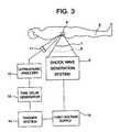
- FIG. 3shows a method for measuring acoustic emission, generated by the transient cavitation bubble cluster 9 induced by the first shock wave pulse 1 , by using a passive cavitation detector 11 , positioned outside a living body 5 and aligned confocally with the focal point of a shock wave generation system 6 .
- the passive cavitation detector 11consisting of one or an array of focussed piezoceramic transducers, with a resonant frequency in the range of 100 KHz to 10 MHz, and a focal length of 4 to 8 inches, is connected to an ultrasound analyzer 12 .
- the shock wave generation system 6initially is set-up to produce a test shock wave pulse with the same pressure waveform as that of the first shock wave pulse 1 , which induces a transient cavitation bubble cluster 9 around the focal point of the shock wave generation system 6 .
- the duration of the growth of the transient cavitation bubble cluster 9can be determined.
- this informationcan then be used to set the time delay generator 13 , connected to a trigger system 14 and a high-voltage supply 15 , to control the shock wave generation system 6 to produce the first shock wave pulse 1 and the second shock wave pulse 2 in sequence with a specified time delay so that the transient cavitation bubble cluster 9 induced by the first shock wave pulse 1 can be forced to collapse at its maximum size by the second shock wave pulse 2 , thus concentrating substantially all of the cavitation energy towards the target concretion 4 for improved stone comminution with reduced tissue injury.
- the first shock wave pulse 1 and the second shock wave pulse 2can be sent in such a configuration that these shock wave pulses propagate along different pathways in the interposed tissue before arriving at the target concretion 4 .
- these two shock wave pulseshave a common focus, and this focus is at or near the target concretion 4 .
- a particular advantage of this embodimentis that the first shock wave pulse 1 and the second shock wave pulse 2 will not interact with each other along the interposed tissue pathway. Therefore, intensive shock wave-cavitation bubble interaction will not occur in the interposed tissue along the shock wave pathways, but will be produced near the target concretion 4 .
- this embodimenthas the advantage of enhancing stone fragmentation efficiency with reduced tissue injury.
Landscapes
- Health & Medical Sciences (AREA)
- Surgery (AREA)
- Life Sciences & Earth Sciences (AREA)
- Heart & Thoracic Surgery (AREA)
- Molecular Biology (AREA)
- Vascular Medicine (AREA)
- Engineering & Computer Science (AREA)
- Biomedical Technology (AREA)
- Orthopedic Medicine & Surgery (AREA)
- Medical Informatics (AREA)
- Nuclear Medicine, Radiotherapy & Molecular Imaging (AREA)
- Animal Behavior & Ethology (AREA)
- General Health & Medical Sciences (AREA)
- Public Health (AREA)
- Veterinary Medicine (AREA)
- Disintegrating Or Milling (AREA)
- Surgical Instruments (AREA)
- Crushing And Grinding (AREA)
Abstract
Description
Claims (11)
- Apparatus for comminuting concretions (4) locatedwithin a living body, said apparatus comprising(a) means (6) producing a first shock wave pulse (1)in a liquid, said first shock wave pulse (1) having acompressive phase with a peak amplitude whosemagnitude is greater than 20 million pascals and witha duration of 1 to 2 microseconds, and said firstshock wave pulse (1) having a tensile phase with apeak amplitude whose magnitude is greater than 1million pascals and with a duration of 2 to 5microseconds,(b) means focussing said first shock wave pulse (1) toproduce a transient cavitation bubble cluster (9) in avolume embracing said concretions (4), said volumebeing less than 65 cubic centimeters,(c) means (6) producing a second shock wave pulse (2)in said liquid, said second shock wave pulse (2) beingproduced after a time delay (3) that is between 50 and400 microseconds after said first shock wave pulse(1), said second shock wave pulse (2) having acompressive phase with a peak amplitude whosemagnitude is between 2 and 100 million pascals andwith a duration between 2 and 40 microseconds,(d) means focussing said second shock wave pulse (2)in said volume, such that said transient acousticcavitation bubble cluster (9) is forced to collapseby said second shock wave pulse (2) thereby producingliquid jets (10), said jets (10) impinging on saidconcretions (4) whereby said concretion (4)comminution is increased.
- Apparatus as claimed in Claim 1, wherein saidfirst acoustic pulse (1) is produced by means of a shockwave generation system (6) selected from the group ofshock wave generation systems (6) consisting ofelectrohydraulic, electromagnetic, and piezoelectric shockwave generation systems.
- Apparatus as claimed in Claim 1, wherein saidsecond shock wave pulse (2) is produced by means of thesuperposition of shock wave pulses of differentamplitudes, frequencies, and phases, produced byenergizing of an array of piezoelectric elements mountedon an inner surface of a spherical cap with saidenergizing of said piezoelectric elements being controlledelectronically.
- Apparatus according to any preceding claim, forcomminuting concretions (4) located within a living body,wherein said concretions (4) are separated from a surfaceof said living body by interposed tissue, and wherein saidapparatus is arranged to(a) produce a test shock wave pulse in a liquid, said testshock wave pulse having a compressive phase with apeak amplitude whose magnitude is greater than 20million pascals and with a duration of 1 to 2microseconds, and said first shock wave pulse having atensile phase with a peak amplitude whose magnitude isgreater than 1 million pascals and with a duration of2 to 5 microseconds,(b) focus said test shock wave pulse to produce a testtransient cavitation bubble cluster, said testtransient cavitation bubble cluster producing an acoustic emission through an initial expansion,subsequent collapse and rebound of said test transientcavitation bubble cluster in a volume embracing saidconcretions, said volume being less than 65 cubiccentimeters,(c) measure said acoustic emission produced by said testtransient cavitation bubble cluster, induced by saidtest shock wave pulse, and determine a duration ofgrowth of said test transient cavitation bubblecluster,(d) produce a first shock wave pulse (1) in said liquid,said first shock wave pulse (1) having a compressivephase with a peak amplitude whose magnitude is greaterthan 20 million pascals and with a duration of 1 to 2microseconds, said first shock wave pulse (1) having atensile phase with a peak amplitude whose magnitude isgreater than 1 million pascals and with a duration of2 to 5 microseconds,(e) focus said first shock wave pulse (1) to produce atransient cavitation bubble cluster (9) in a volumeembracing said concretions (4), said volume being lessthan 65 cubic centimeters,(f) produce a second shock wave pulse (2) in sequence tosaid first shock wave pulse (1) in said liquid, saidsecond shock wave pulse (2) having a compressive phasewith a peak amplitude whose magnitude is between 2 and100 million pascals and with a duration between 2 and40 microseconds, said second shock wave pulse (2)being produced at a specified time delay (3) aftersaid production of said first shock wave pulse (1),said specified time delay (3) being equal to saidduration of growth of said test transient cavitationbubble cluster,(g) focus said second shock wave pulse (2) in said volume,whereby said transient acoustic cavitation bubblecluster (9) is collapsed by said second shock wavepulse (2) thereby producing liquid jets (10), saidjets (10) impinging on said concretions (4), wherebysaid concretion (4) is comminuted.
- Apparatus for comminuting concretions (4) as disclosedin Claim 4, including a passive cavitation detector (11)and an ultrasound analyzer (12), wherein said acousticemission is measured by using said passive cavitationdetector (11), said duration of growth of said testtransient cavitation bubble cluster being determined bysaid ultrasound analyzer (12).
- Apparatus for comminuting concretions (4) as disclosedin Claim 4, wherein said specified time delay (3) betweensaid production of said first shock wave pulse (1) andsaid production of said second shock wave pulse (2), isdetermined using a time delay generator (13), a triggersystem (14) and a high voltage supply (15)connected with said shock wave generation system (6) based on said duration of growth of said test transientcavitation bubble cluster (9).
- Apparatus according to any of Claims 1 to 3 forcomminuting concretions (4) located within a living body,wherein said concretions are separated from a surface ofsaid body by interposed tissue, and wherein said apparatusis arranged to(a) produce a first shock wave pulse (1) in a liquid, saidfirst shock wave pulse (1) having a compressive phasewith a peak amplitude whose magnitude is greater than20 million pascals and with a duration of 1 to 2microseconds, and said first shock wave pulse (1)having a tensile phase with a peak amplitude whosemagnitude is greater than 1 million pascals and with aduration of 2 to 5 microseconds,(b) focus said first shock wave pulse (1) to produce atransient cavitation bubble cluster (9) in a volumeembracing said concretions (4) with said volume beingless than 65 cubic centimeters,(c) produce a second shock wave pulse (2) in said liquid,said second shock wave pulse (2) being produced aftera time delay (3) that is between 50 and 400microseconds after said first shock wave pulse, andsecond shock wave pulse (2) having a compressive phasewith a peak amplitude whose magnitude is between 2 and100 million pascals and with a duration between 2 and40 microseconds,(d) send said first shock pulse (1) and said second shockwave pulse (2)along different pathways in said interposed tissue before arriving at saidconcretions,(e) focus said second shock wave pulse (2) in said volume,whereby said transient acoustic cavitation bubblecluster (9) is forced to collapse by said secondshock wave pulse (2) thereby producing liquid jets(10), said jets (10) impinging on said concretions(4), whereby said concretion (4) is comminuted.
- Apparatus for comminuting concretions (4) as claimedin Claim 7, wherein said first shock wave pulse (1)and said second shock wave pulse (2) propagate alongcoaxial pathways.
- Apparatus for comminuting concretions (4) as claimedin Claim 7, wherein said first shock wave pulse (1)and said second shock wave pulse (2) propagate alongsaid different pathways in said interposed tissuebefore arriving at a common focus which has a volumeless than 65 cubic centimeters.
- Apparatus for comminuting concretions (4) as disclosedin any proceeding claim, wherein said liquid is waterand said liquid jets (10) are water jets.
- Use of means producing a first shock wave pulse ina liquid, means focussing said first shock wavepulse, means producing a second shock wave pulsein said liquid and means focussing said secondshock wave pulse, in the manufacture of an apparatus for the comminutionof concretions located within a living bodyas claimed in any preceding claim.
Applications Claiming Priority (3)
| Application Number | Priority Date | Filing Date | Title |
|---|---|---|---|
| US08/509,770US5582578A (en) | 1995-08-01 | 1995-08-01 | Method for the comminution of concretions |
| US509770 | 1995-08-01 | ||
| PCT/US1996/009874WO1997004710A1 (en) | 1995-08-01 | 1996-06-10 | Method for the comminution of concretions |
Publications (3)
| Publication Number | Publication Date |
|---|---|
| EP0955911A1 EP0955911A1 (en) | 1999-11-17 |
| EP0955911A4 EP0955911A4 (en) | 2000-01-05 |
| EP0955911B1true EP0955911B1 (en) | 2004-02-11 |
Family
ID=24028019
Family Applications (1)
| Application Number | Title | Priority Date | Filing Date |
|---|---|---|---|
| EP96922426AExpired - LifetimeEP0955911B1 (en) | 1995-08-01 | 1996-06-10 | Device for the comminution of concretions |
Country Status (6)
| Country | Link |
|---|---|
| US (1) | US5582578A (en) |
| EP (1) | EP0955911B1 (en) |
| AT (1) | ATE259188T1 (en) |
| AU (1) | AU6330196A (en) |
| DE (1) | DE69631555T2 (en) |
| WO (1) | WO1997004710A1 (en) |
Families Citing this family (117)
| Publication number | Priority date | Publication date | Assignee | Title |
|---|---|---|---|---|
| US5800365A (en)* | 1995-12-14 | 1998-09-01 | Duke University | Microsecond tandem-pulse electrohydraulic shock wave generator with confocal reflectors |
| US6405069B1 (en) | 1996-01-31 | 2002-06-11 | Board Of Regents, The University Of Texas System | Time-resolved optoacoustic method and system for noninvasive monitoring of glucose |
| US6309352B1 (en) | 1996-01-31 | 2001-10-30 | Board Of Regents, The University Of Texas System | Real time optoacoustic monitoring of changes in tissue properties |
| US5840023A (en)* | 1996-01-31 | 1998-11-24 | Oraevsky; Alexander A. | Optoacoustic imaging for medical diagnosis |
| US5725482A (en)* | 1996-02-09 | 1998-03-10 | Bishop; Richard P. | Method for applying high-intensity ultrasonic waves to a target volume within a human or animal body |
| US6123679A (en)* | 1996-08-29 | 2000-09-26 | Lafaut; Jean-Pierre | Method for extracorporeal shock wave lithotripsy by applying an acoustic shock wave followed by a limited oscillating acoustic pressure wave train |
| US7169123B2 (en) | 1997-01-22 | 2007-01-30 | Advanced Medical Optics, Inc. | Control of pulse duty cycle based upon footswitch displacement |
| US6780165B2 (en) | 1997-01-22 | 2004-08-24 | Advanced Medical Optics | Micro-burst ultrasonic power delivery |
| US6298264B1 (en) | 1998-08-31 | 2001-10-02 | Duke University | Apparatus and method for macromolecule delivery into living cells |
| US6309355B1 (en) | 1998-12-22 | 2001-10-30 | The Regents Of The University Of Michigan | Method and assembly for performing ultrasound surgery using cavitation |
| EP1169088A1 (en)* | 1999-03-08 | 2002-01-09 | Angiosonics Inc. | Dual transducer ultrasound lysis method and apparatus |
| WO2001010295A1 (en) | 1999-08-06 | 2001-02-15 | The Board Of Regents Of The University Of Texas System | Optoacoustic monitoring of blood oxygenation |
| US6751490B2 (en) | 2000-03-01 | 2004-06-15 | The Board Of Regents Of The University Of Texas System | Continuous optoacoustic monitoring of hemoglobin concentration and hematocrit |
| US6618620B1 (en) | 2000-11-28 | 2003-09-09 | Txsonics Ltd. | Apparatus for controlling thermal dosing in an thermal treatment system |
| US6488494B2 (en) | 2001-01-18 | 2002-12-03 | Joy World, Inc. | Candle holder |
| FR2830468B1 (en)* | 2001-10-04 | 2004-02-20 | Inst Nat Sante Rech Med | DEVICE AND METHOD FOR PRODUCING HIGH PRESSURE ULTRASONIC PULSES |
| US6770039B2 (en) | 2001-11-09 | 2004-08-03 | Duke University | Method to reduce tissue injury in shock wave lithotripsy |
| US6997935B2 (en)* | 2001-11-20 | 2006-02-14 | Advanced Medical Optics, Inc. | Resonant converter tuning for maintaining substantially constant phaco handpiece power under increased load |
| DE10158519B4 (en)* | 2001-11-29 | 2005-01-13 | Dornier Medtech Holding International Gmbh | Shock and shock wave therapy device |
| US7485101B1 (en) | 2002-03-22 | 2009-02-03 | Faragalla Yousry B | Multiple shockwave focal treatment apparatus with targeting positioning and locating apparatus |
| US6780161B2 (en) | 2002-03-22 | 2004-08-24 | Fmd, Llc | Apparatus for extracorporeal shock wave lithotripter using at least two shock wave pulses |
| DE10234144A1 (en)* | 2002-07-26 | 2004-02-05 | Dornier Medtech Gmbh | lithotripter |
| US7316664B2 (en)* | 2002-10-21 | 2008-01-08 | Advanced Medical Optics, Inc. | Modulated pulsed ultrasonic power delivery system and method |
| US20040092921A1 (en)* | 2002-10-21 | 2004-05-13 | Kadziauskas Kenneth E. | System and method for pulsed ultrasonic power delivery employing cavitation effects |
| US7077820B1 (en) | 2002-10-21 | 2006-07-18 | Advanced Medical Optics, Inc. | Enhanced microburst ultrasonic power delivery system and method |
| US8088067B2 (en) | 2002-12-23 | 2012-01-03 | Insightec Ltd. | Tissue aberration corrections in ultrasound therapy |
| EP2604235A1 (en)* | 2003-03-12 | 2013-06-19 | Abbott Medical Optics Inc. | System and method for pulsed ultrasonic power delivery employing cavitation effects |
| AU2004233870B2 (en)* | 2003-04-24 | 2009-11-05 | The Board Of Regents Of The University Of Texas System | Noninvasive blood analysis by optical probing of the veins under the tongue |
| US7611462B2 (en) | 2003-05-22 | 2009-11-03 | Insightec-Image Guided Treatment Ltd. | Acoustic beam forming in phased arrays including large numbers of transducer elements |
| US7846126B2 (en)* | 2003-07-14 | 2010-12-07 | Abbott Medical Optics, Inc. | System and method for modulated surgical procedure irrigation and aspiration |
| AU2003262631A1 (en)* | 2003-08-14 | 2005-03-10 | Duke University | Apparatus for improved shock-wave lithotripsy (swl) using a piezoelectric annular array (peaa) shock-wave generator in combination with a primary shock wave |
| US20050038361A1 (en)* | 2003-08-14 | 2005-02-17 | Duke University | Apparatus for improved shock-wave lithotripsy (SWL) using a piezoelectric annular array (PEAA) shock-wave generator in combination with a primary shock wave source |
| US8409099B2 (en) | 2004-08-26 | 2013-04-02 | Insightec Ltd. | Focused ultrasound system for surrounding a body tissue mass and treatment method |
| US20060060991A1 (en)* | 2004-09-21 | 2006-03-23 | Interuniversitair Microelektronica Centrum (Imec) | Method and apparatus for controlled transient cavitation |
| US20070016039A1 (en) | 2005-06-21 | 2007-01-18 | Insightec-Image Guided Treatment Ltd. | Controlled, non-linear focused ultrasound treatment |
| DE102005037043C5 (en) | 2005-08-05 | 2017-12-14 | Dornier Medtech Systems Gmbh | Shock wave therapy device with image acquisition |
| US10219815B2 (en) | 2005-09-22 | 2019-03-05 | The Regents Of The University Of Michigan | Histotripsy for thrombolysis |
| US8057408B2 (en)* | 2005-09-22 | 2011-11-15 | The Regents Of The University Of Michigan | Pulsed cavitational ultrasound therapy |
| JP5087007B2 (en) | 2005-11-23 | 2012-11-28 | インサイテック・リミテッド | Hierarchical switching ultra high density ultrasonic array |
| US8235901B2 (en)* | 2006-04-26 | 2012-08-07 | Insightec, Ltd. | Focused ultrasound system with far field tail suppression |
| DE102006021049A1 (en)* | 2006-05-05 | 2007-11-08 | Siemens Ag | Shock wave head for a shock wave treatment device and method for fragmentation and control of fragmentation of a fragmentation object located in an examination subject |
| ITVR20060113A1 (en)* | 2006-06-07 | 2008-01-07 | Giglio Antonio Del | DEVICE FOR THE TREATMENT OF ADIPOSE SUBCUTANEOUS FABRIC BY NON-FOICALIZED AND OPPOSED SHOCKWAVES |
| US7785336B2 (en) | 2006-08-01 | 2010-08-31 | Abbott Medical Optics Inc. | Vacuum sense control for phaco pulse shaping |
| WO2008157422A1 (en)* | 2007-06-13 | 2008-12-24 | Charles Thomas Hardy | Materials, methods, and systems for cavitation-mediated ultrasonic drug delivery |
| US8251908B2 (en) | 2007-10-01 | 2012-08-28 | Insightec Ltd. | Motion compensated image-guided focused ultrasound therapy system |
| US20090247911A1 (en)* | 2008-03-25 | 2009-10-01 | Petr Novak | Multiple-angle switched high intensity focused ultrasound |
| US8000878B2 (en)* | 2008-05-15 | 2011-08-16 | Honeywell International Inc. | Parallel sequential turbocharger architecture using engine cylinder variable valve lift system |
| WO2009152352A2 (en) | 2008-06-13 | 2009-12-17 | Aspen Medtech, Inc. | Shockwave balloon catheter system |
| US9072534B2 (en)* | 2008-06-13 | 2015-07-07 | Shockwave Medical, Inc. | Non-cavitation shockwave balloon catheter system |
| US10702293B2 (en) | 2008-06-13 | 2020-07-07 | Shockwave Medical, Inc. | Two-stage method for treating calcified lesions within the wall of a blood vessel |
| US9180280B2 (en) | 2008-11-04 | 2015-11-10 | Shockwave Medical, Inc. | Drug delivery shockwave balloon catheter system |
| US9044618B2 (en) | 2008-11-05 | 2015-06-02 | Shockwave Medical, Inc. | Shockwave valvuloplasty catheter system |
| US8425424B2 (en) | 2008-11-19 | 2013-04-23 | Inightee Ltd. | Closed-loop clot lysis |
| US8617073B2 (en) | 2009-04-17 | 2013-12-31 | Insightec Ltd. | Focusing ultrasound into the brain through the skull by utilizing both longitudinal and shear waves |
| US9623266B2 (en) | 2009-08-04 | 2017-04-18 | Insightec Ltd. | Estimation of alignment parameters in magnetic-resonance-guided ultrasound focusing |
| WO2011022411A2 (en) | 2009-08-17 | 2011-02-24 | Histosonics, Inc. | Disposable acoustic coupling medium container |
| US9289154B2 (en) | 2009-08-19 | 2016-03-22 | Insightec Ltd. | Techniques for temperature measurement and corrections in long-term magnetic resonance thermometry |
| EP2467071B1 (en) | 2009-08-19 | 2019-09-18 | Duke University | Acoustic lens for shockwave lithotripsy |
| JP5726191B2 (en)* | 2009-08-26 | 2015-05-27 | リージェンツ オブ ザ ユニバーシティー オブ ミシガン | Apparatus and method using control of bubble turbidity cavitation phenomenon during fracture of ureteral stones |
| WO2011024074A2 (en) | 2009-08-26 | 2011-03-03 | Insightec Ltd. | Asymmetric phased-array ultrasound transducer |
| JP5863654B2 (en) | 2009-08-26 | 2016-02-16 | リージェンツ オブ ザ ユニバーシティー オブ ミシガン | Micromanipulator control arm for therapeutic and image processing ultrasonic transducers |
| US8539813B2 (en) | 2009-09-22 | 2013-09-24 | The Regents Of The University Of Michigan | Gel phantoms for testing cavitational ultrasound (histotripsy) transducers |
| EP2489034B1 (en) | 2009-10-14 | 2016-11-30 | Insightec Ltd. | Mapping ultrasound transducers |
| US8368401B2 (en) | 2009-11-10 | 2013-02-05 | Insightec Ltd. | Techniques for correcting measurement artifacts in magnetic resonance thermometry |
| US8932237B2 (en) | 2010-04-28 | 2015-01-13 | Insightec, Ltd. | Efficient ultrasound focusing |
| US9852727B2 (en) | 2010-04-28 | 2017-12-26 | Insightec, Ltd. | Multi-segment ultrasound transducers |
| US9981148B2 (en) | 2010-10-22 | 2018-05-29 | Insightec, Ltd. | Adaptive active cooling during focused ultrasound treatment |
| US9144694B2 (en) | 2011-08-10 | 2015-09-29 | The Regents Of The University Of Michigan | Lesion generation through bone using histotripsy therapy without aberration correction |
| US12402802B2 (en) | 2011-08-31 | 2025-09-02 | Insightec Ltd. | Avoiding MRI-interference with co-existing systems |
| US9050627B2 (en) | 2011-09-02 | 2015-06-09 | Abbott Medical Optics Inc. | Systems and methods for ultrasonic power measurement and control of phacoemulsification systems |
| US8574247B2 (en) | 2011-11-08 | 2013-11-05 | Shockwave Medical, Inc. | Shock wave valvuloplasty device with moveable shock wave generator |
| US9049783B2 (en) | 2012-04-13 | 2015-06-02 | Histosonics, Inc. | Systems and methods for obtaining large creepage isolation on printed circuit boards |
| WO2013166019A1 (en) | 2012-04-30 | 2013-11-07 | The Regents Of The University Of Michigan | Ultrasound transducer manufacturing using rapid-prototyping method |
| US9642673B2 (en) | 2012-06-27 | 2017-05-09 | Shockwave Medical, Inc. | Shock wave balloon catheter with multiple shock wave sources |
| AU2013300176B2 (en) | 2012-08-06 | 2017-08-17 | Shockwave Medical, Inc. | Low profile electrodes for an angioplasty shock wave catheter |
| CA2881184C (en) | 2012-08-06 | 2019-06-04 | Shockwave Medical, Inc. | Shockwave catheter |
| US9554815B2 (en) | 2012-08-08 | 2017-01-31 | Shockwave Medical, Inc. | Shockwave valvuloplasty with multiple balloons |
| US9138249B2 (en) | 2012-08-17 | 2015-09-22 | Shockwave Medical, Inc. | Shock wave catheter system with arc preconditioning |
| US9333000B2 (en) | 2012-09-13 | 2016-05-10 | Shockwave Medical, Inc. | Shockwave catheter system with energy control |
| US9522012B2 (en) | 2012-09-13 | 2016-12-20 | Shockwave Medical, Inc. | Shockwave catheter system with energy control |
| US20140100459A1 (en) | 2012-10-05 | 2014-04-10 | The Regents Of The University Of Michigan | Bubble-induced color doppler feedback during histotripsy |
| EP3016594B1 (en) | 2013-07-03 | 2023-01-25 | Histosonics, Inc. | Histotripsy excitation sequences optimized for bubble cloud formation using shock scattering |
| WO2015003154A1 (en) | 2013-07-03 | 2015-01-08 | Histosonics, Inc. | Articulating arm limiter for cavitational ultrasound therapy system |
| US10780298B2 (en) | 2013-08-22 | 2020-09-22 | The Regents Of The University Of Michigan | Histotripsy using very short monopolar ultrasound pulses |
| US9730715B2 (en) | 2014-05-08 | 2017-08-15 | Shockwave Medical, Inc. | Shock wave guide wire |
| US10624660B2 (en)* | 2015-01-20 | 2020-04-21 | Guided Therapy Systems, Llc | Methods and systems for removal of a foreign object from tissue |
| JP6979882B2 (en) | 2015-06-24 | 2021-12-15 | ザ リージェンツ オブ ザ ユニヴァシティ オブ ミシガン | Tissue disruption therapy systems and methods for the treatment of brain tissue |
| WO2017087195A1 (en) | 2015-11-18 | 2017-05-26 | Shockwave Medical, Inc. | Shock wave electrodes |
| US10226265B2 (en) | 2016-04-25 | 2019-03-12 | Shockwave Medical, Inc. | Shock wave device with polarity switching |
| AU2017339980B2 (en) | 2016-10-06 | 2022-08-18 | Shockwave Medical, Inc. | Aortic leaflet repair using shock wave applicators |
| US10357264B2 (en) | 2016-12-06 | 2019-07-23 | Shockwave Medical, Inc. | Shock wave balloon catheter with insertable electrodes |
| US10441300B2 (en) | 2017-04-19 | 2019-10-15 | Shockwave Medical, Inc. | Drug delivery shock wave balloon catheter system |
| US11020135B1 (en) | 2017-04-25 | 2021-06-01 | Shockwave Medical, Inc. | Shock wave device for treating vascular plaques |
| US10966737B2 (en) | 2017-06-19 | 2021-04-06 | Shockwave Medical, Inc. | Device and method for generating forward directed shock waves |
| US10709462B2 (en) | 2017-11-17 | 2020-07-14 | Shockwave Medical, Inc. | Low profile electrodes for a shock wave catheter |
| EP3809988B1 (en) | 2018-06-21 | 2023-06-07 | Shockwave Medical, Inc. | System for treating occlusions in body lumens |
| AU2019389001B2 (en) | 2018-11-28 | 2025-08-14 | Histosonics, Inc. | Histotripsy systems and methods |
| CN110269937A (en)* | 2019-07-23 | 2019-09-24 | 山东百多安医疗器械有限公司 | A kind of targeted microbubble and preparation method thereof for gall stone ultrasonic therapy |
| EP4512350A3 (en) | 2019-09-24 | 2025-05-07 | Shockwave Medical, Inc. | Low profile electrodes for a shock wave catheter |
| WO2021061523A1 (en) | 2019-09-24 | 2021-04-01 | Shockwave Medical, Inc. | System for treating thrombus in body lumens |
| WO2021061451A1 (en) | 2019-09-24 | 2021-04-01 | Shockwave Medical, Inc. | Lesion crossing shock wave catheter |
| US11877953B2 (en) | 2019-12-26 | 2024-01-23 | Johnson & Johnson Surgical Vision, Inc. | Phacoemulsification apparatus |
| US11813485B2 (en) | 2020-01-28 | 2023-11-14 | The Regents Of The University Of Michigan | Systems and methods for histotripsy immunosensitization |
| JP2023540482A (en) | 2020-08-27 | 2023-09-25 | ザ リージェンツ オブ ザ ユニバーシティー オブ ミシガン | Ultrasonic transducer with transmitting and receiving functions for histotripsy |
| US11992232B2 (en) | 2020-10-27 | 2024-05-28 | Shockwave Medical, Inc. | System for treating thrombus in body lumens |
| US12178750B2 (en) | 2020-11-23 | 2024-12-31 | Johnson & Johnson Surgical Vision, Inc. | Removal of cataract debris |
| US12232755B2 (en) | 2020-12-11 | 2025-02-25 | Shockwave Medical, Inc. | Lesion crossing shock wave catheter |
| US12324770B2 (en) | 2021-04-15 | 2025-06-10 | Johnson & Johnson Surgical Vision, Inc. | Compensating for imperfect behavior of multi-piezoelectric crystal |
| US12023098B2 (en) | 2021-10-05 | 2024-07-02 | Shockwave Medical, Inc. | Lesion crossing shock wave catheter |
| EP4608504A1 (en) | 2022-10-28 | 2025-09-03 | Histosonics, Inc. | Histotripsy systems and methods |
| US12290268B2 (en) | 2023-03-31 | 2025-05-06 | Shockwave Medical, Inc. | Shockwave catheters for treating rhinosinusitis |
| US12035932B1 (en) | 2023-04-21 | 2024-07-16 | Shockwave Medical, Inc. | Intravascular lithotripsy catheter with slotted emitter bands |
| US12220141B2 (en) | 2023-06-29 | 2025-02-11 | Shockwave Medical, Inc. | Catheter system with independently controllable bubble and arc generation |
| US12426904B2 (en) | 2023-11-17 | 2025-09-30 | Shockwave Medical, Inc. | Intravascular lithotripsy catheter with oscillating impactor |
| US12402899B2 (en) | 2023-11-30 | 2025-09-02 | Shockwave Medical, Inc. | Systems, devices, and methods for generating shock waves in a forward direction |
| US12433620B2 (en) | 2024-02-23 | 2025-10-07 | Shockwave Medical, Inc. | Locus emitter shock wave catheter devices with increased longevity and higher sonic output |
| US12178458B1 (en) | 2024-05-16 | 2024-12-31 | Shockwave Medical, Inc. | Guidewireless shock wave catheters |
Citations (1)
| Publication number | Priority date | Publication date | Assignee | Title |
|---|---|---|---|---|
| US5209221A (en)* | 1988-03-01 | 1993-05-11 | Richard Wolf Gmbh | Ultrasonic treatment of pathological tissue |
Family Cites Families (9)
| Publication number | Priority date | Publication date | Assignee | Title |
|---|---|---|---|---|
| CH574734A5 (en)* | 1973-10-12 | 1976-04-30 | Dornier System Gmbh | |
| DE8413031U1 (en)* | 1984-04-27 | 1984-07-05 | Siemens AG, 1000 Berlin und 8000 München | Device for the contactless smashing of concrements |
| DE3501838A1 (en)* | 1985-01-21 | 1986-07-24 | Siemens AG, 1000 Berlin und 8000 München | DEVICE FOR THE GENERATION OF TIMED SHOCK SHAFTS |
| DE3543867C3 (en)* | 1985-12-12 | 1994-10-06 | Wolf Gmbh Richard | Device for the spatial location and destruction of concrements in body cavities |
| DE3607949A1 (en)* | 1986-03-11 | 1987-09-17 | Wolf Gmbh Richard | METHOD FOR DETECTING POSSIBLE TISSUE DAMAGE IN THE MEDICAL APPLICATION OF HIGH-ENERGY SOUND |
| DE3732131A1 (en)* | 1987-09-24 | 1989-04-06 | Wolf Gmbh Richard | FOCUSING ULTRASONIC transducer |
| US5243986A (en)* | 1988-04-30 | 1993-09-14 | Richard Wolf Gmbh | Dissolution of concretions in a bodily cavity |
| FR2643252B1 (en)* | 1989-02-21 | 1991-06-07 | Technomed Int Sa | APPARATUS FOR THE SELECTIVE DESTRUCTION OF CELLS INCLUDING SOFT TISSUES AND BONES WITHIN THE BODY OF A LIVING BODY BY IMPLOSION OF GAS BUBBLES |
| DE3921808A1 (en)* | 1989-07-03 | 1991-01-17 | Schubert Werner | Breaking up internal tumours using shock waves - involves gas bubbles to enhance effect in region of tumour |
- 1995
- 1995-08-01USUS08/509,770patent/US5582578A/ennot_activeExpired - Lifetime
- 1996
- 1996-06-10DEDE69631555Tpatent/DE69631555T2/ennot_activeExpired - Lifetime
- 1996-06-10EPEP96922426Apatent/EP0955911B1/ennot_activeExpired - Lifetime
- 1996-06-10ATAT96922426Tpatent/ATE259188T1/ennot_activeIP Right Cessation
- 1996-06-10WOPCT/US1996/009874patent/WO1997004710A1/enactiveIP Right Grant
- 1996-06-10AUAU63301/96Apatent/AU6330196A/ennot_activeAbandoned
Patent Citations (1)
| Publication number | Priority date | Publication date | Assignee | Title |
|---|---|---|---|---|
| US5209221A (en)* | 1988-03-01 | 1993-05-11 | Richard Wolf Gmbh | Ultrasonic treatment of pathological tissue |
Also Published As
| Publication number | Publication date |
|---|---|
| ATE259188T1 (en) | 2004-02-15 |
| US5582578A (en) | 1996-12-10 |
| WO1997004710A1 (en) | 1997-02-13 |
| AU6330196A (en) | 1997-02-26 |
| DE69631555T2 (en) | 2004-12-23 |
| EP0955911A1 (en) | 1999-11-17 |
| DE69631555D1 (en) | 2004-03-18 |
| EP0955911A4 (en) | 2000-01-05 |
Similar Documents
| Publication | Publication Date | Title |
|---|---|---|
| EP0955911B1 (en) | Device for the comminution of concretions | |
| US5800365A (en) | Microsecond tandem-pulse electrohydraulic shock wave generator with confocal reflectors | |
| US20050038361A1 (en) | Apparatus for improved shock-wave lithotripsy (SWL) using a piezoelectric annular array (PEAA) shock-wave generator in combination with a primary shock wave source | |
| US10772646B2 (en) | Method for controlling histotripsy using confocal fundamental and harmonic superposition combined with hundred-microsecond ultrasound pulses | |
| US5158070A (en) | Method for the localized destruction of soft structures using negative pressure elastic waves | |
| US3942531A (en) | Apparatus for breaking-up, without contact, concrements present in the body of a living being | |
| EP3016594B1 (en) | Histotripsy excitation sequences optimized for bubble cloud formation using shock scattering | |
| KR100991846B1 (en) | Shock-Ultrasonic Integrated Therapy | |
| US6770039B2 (en) | Method to reduce tissue injury in shock wave lithotripsy | |
| Williams et al. | The histotripsy spectrum: differences and similarities in techniques and instrumentation | |
| EP1701659A1 (en) | Apparatus for improved shock-wave lithotripsy (swl) using a piezoelectric annular array (peaa) shock-wave generator in combination with a primary shock wave | |
| US20060184072A1 (en) | Ultrasonic medical treatment device with variable focal zone | |
| EP1651120B1 (en) | Shockwave generating system | |
| CN101437459A (en) | Shock wave head for a shock wave treatment apparatus and method for the fragmentation of and for controlling the fragmentation of a fragmentation object arranged in an object under investigation | |
| JP2012239791A (en) | Focused sonic therapeutic apparatus | |
| US20040068209A1 (en) | Focused shock-wave devices with direct wave cavitation suppressor | |
| EP2467071B1 (en) | Acoustic lens for shockwave lithotripsy | |
| JP4139916B2 (en) | Ultrasonic irradiation method and ultrasonic irradiation apparatus | |
| Davros et al. | Gallstone lithotripsy: relevant physical principles and technical issues. | |
| RU1804315C (en) | Device for local attack on biology object structure | |
| Maxwell et al. | The role of compressional pressure in the formation of dense bubble clouds in histotripsy | |
| US7033328B2 (en) | Direct wave cavitation suppressor for focused shock-wave devices | |
| Lu et al. | Histotripsy produced by dual frequency of fundamental and harmonic superimposition with protocol of hundred-microsecond-length pulses and two stages | |
| Pond | The generation and use of asymmetric waves to produce enhanced forces for phonophoresis and medical therapy | |
| Osuga et al. | 2P5-2 Acceleration of Lithotripsy Using Cavitation Bubbles Induced by Second-harmonic Superimposition |
Legal Events
| Date | Code | Title | Description |
|---|---|---|---|
| PUAI | Public reference made under article 153(3) epc to a published international application that has entered the european phase | Free format text:ORIGINAL CODE: 0009012 | |
| 17P | Request for examination filed | Effective date:19980302 | |
| AK | Designated contracting states | Kind code of ref document:A1 Designated state(s):AT BE CH DE DK ES FI FR GB GR IE IT LI LU MC NL PT SE | |
| A4 | Supplementary search report drawn up and despatched | Effective date:19991122 | |
| AK | Designated contracting states | Kind code of ref document:A4 Designated state(s):AT BE CH DE DK ES FI FR GB GR IE IT LI LU MC NL PT SE | |
| 17Q | First examination report despatched | Effective date:20020925 | |
| RTI1 | Title (correction) | Free format text:DEVICE FOR THE COMMINUTION OF CONCRETIONS | |
| GRAP | Despatch of communication of intention to grant a patent | Free format text:ORIGINAL CODE: EPIDOSNIGR1 | |
| RTI1 | Title (correction) | Free format text:DEVICE FOR THE COMMINUTION OF CONCRETIONS | |
| GRAS | Grant fee paid | Free format text:ORIGINAL CODE: EPIDOSNIGR3 | |
| GRAA | (expected) grant | Free format text:ORIGINAL CODE: 0009210 | |
| RAP1 | Party data changed (applicant data changed or rights of an application transferred) | Owner name:DUKE UNIVERSITY | |
| AK | Designated contracting states | Kind code of ref document:B1 Designated state(s):AT BE CH DE DK ES FI FR GB GR IE IT LI LU MC NL PT SE | |
| PG25 | Lapsed in a contracting state [announced via postgrant information from national office to epo] | Ref country code:NL Free format text:LAPSE BECAUSE OF FAILURE TO SUBMIT A TRANSLATION OF THE DESCRIPTION OR TO PAY THE FEE WITHIN THE PRESCRIBED TIME-LIMIT Effective date:20040211 Ref country code:LI Free format text:LAPSE BECAUSE OF FAILURE TO SUBMIT A TRANSLATION OF THE DESCRIPTION OR TO PAY THE FEE WITHIN THE PRESCRIBED TIME-LIMIT Effective date:20040211 Ref country code:IT Free format text:LAPSE BECAUSE OF FAILURE TO SUBMIT A TRANSLATION OF THE DESCRIPTION OR TO PAY THE FEE WITHIN THE PRE;WARNING: LAPSES OF ITALIAN PATENTS WITH EFFECTIVE DATE BEFORE 2007 MAY HAVE OCCURRED AT ANY TIME BEFORE 2007. THE CORRECT EFFECTIVE DATE MAY BE DIFFERENT FROM THE ONE RECORDED.SCRIBED TIME-LIMIT Effective date:20040211 Ref country code:FR Free format text:LAPSE BECAUSE OF FAILURE TO SUBMIT A TRANSLATION OF THE DESCRIPTION OR TO PAY THE FEE WITHIN THE PRESCRIBED TIME-LIMIT Effective date:20040211 Ref country code:FI Free format text:LAPSE BECAUSE OF FAILURE TO SUBMIT A TRANSLATION OF THE DESCRIPTION OR TO PAY THE FEE WITHIN THE PRESCRIBED TIME-LIMIT Effective date:20040211 Ref country code:CH Free format text:LAPSE BECAUSE OF FAILURE TO SUBMIT A TRANSLATION OF THE DESCRIPTION OR TO PAY THE FEE WITHIN THE PRESCRIBED TIME-LIMIT Effective date:20040211 Ref country code:BE Free format text:LAPSE BECAUSE OF FAILURE TO SUBMIT A TRANSLATION OF THE DESCRIPTION OR TO PAY THE FEE WITHIN THE PRESCRIBED TIME-LIMIT Effective date:20040211 Ref country code:AT Free format text:LAPSE BECAUSE OF FAILURE TO SUBMIT A TRANSLATION OF THE DESCRIPTION OR TO PAY THE FEE WITHIN THE PRESCRIBED TIME-LIMIT Effective date:20040211 | |
| REG | Reference to a national code | Ref country code:GB Ref legal event code:FG4D | |
| REG | Reference to a national code | Ref country code:CH Ref legal event code:EP | |
| REG | Reference to a national code | Ref country code:IE Ref legal event code:FG4D | |
| REF | Corresponds to: | Ref document number:69631555 Country of ref document:DE Date of ref document:20040318 Kind code of ref document:P | |
| PG25 | Lapsed in a contracting state [announced via postgrant information from national office to epo] | Ref country code:SE Free format text:LAPSE BECAUSE OF FAILURE TO SUBMIT A TRANSLATION OF THE DESCRIPTION OR TO PAY THE FEE WITHIN THE PRESCRIBED TIME-LIMIT Effective date:20040511 Ref country code:GR Free format text:LAPSE BECAUSE OF FAILURE TO SUBMIT A TRANSLATION OF THE DESCRIPTION OR TO PAY THE FEE WITHIN THE PRESCRIBED TIME-LIMIT Effective date:20040511 Ref country code:DK Free format text:LAPSE BECAUSE OF FAILURE TO SUBMIT A TRANSLATION OF THE DESCRIPTION OR TO PAY THE FEE WITHIN THE PRESCRIBED TIME-LIMIT Effective date:20040511 | |
| PG25 | Lapsed in a contracting state [announced via postgrant information from national office to epo] | Ref country code:ES Free format text:LAPSE BECAUSE OF FAILURE TO SUBMIT A TRANSLATION OF THE DESCRIPTION OR TO PAY THE FEE WITHIN THE PRESCRIBED TIME-LIMIT Effective date:20040522 | |
| PG25 | Lapsed in a contracting state [announced via postgrant information from national office to epo] | Ref country code:LU Free format text:LAPSE BECAUSE OF NON-PAYMENT OF DUE FEES Effective date:20040610 Ref country code:IE Free format text:LAPSE BECAUSE OF NON-PAYMENT OF DUE FEES Effective date:20040610 | |
| PG25 | Lapsed in a contracting state [announced via postgrant information from national office to epo] | Ref country code:MC Free format text:LAPSE BECAUSE OF NON-PAYMENT OF DUE FEES Effective date:20040630 | |
| NLV1 | Nl: lapsed or annulled due to failure to fulfill the requirements of art. 29p and 29m of the patents act | ||
| REG | Reference to a national code | Ref country code:CH Ref legal event code:PL | |
| PLBE | No opposition filed within time limit | Free format text:ORIGINAL CODE: 0009261 | |
| STAA | Information on the status of an ep patent application or granted ep patent | Free format text:STATUS: NO OPPOSITION FILED WITHIN TIME LIMIT | |
| EN | Fr: translation not filed | ||
| 26N | No opposition filed | Effective date:20041112 | |
| REG | Reference to a national code | Ref country code:IE Ref legal event code:MM4A | |
| PGFP | Annual fee paid to national office [announced via postgrant information from national office to epo] | Ref country code:GB Payment date:20050622 Year of fee payment:10 | |
| PG25 | Lapsed in a contracting state [announced via postgrant information from national office to epo] | Ref country code:GB Free format text:LAPSE BECAUSE OF NON-PAYMENT OF DUE FEES Effective date:20060610 | |
| GBPC | Gb: european patent ceased through non-payment of renewal fee | Effective date:20060610 | |
| PG25 | Lapsed in a contracting state [announced via postgrant information from national office to epo] | Ref country code:PT Free format text:LAPSE BECAUSE OF NON-PAYMENT OF DUE FEES Effective date:20040711 | |
| PGFP | Annual fee paid to national office [announced via postgrant information from national office to epo] | Ref country code:DE Payment date:20110608 Year of fee payment:16 | |
| REG | Reference to a national code | Ref country code:DE Ref legal event code:R119 Ref document number:69631555 Country of ref document:DE Effective date:20130101 | |
| PG25 | Lapsed in a contracting state [announced via postgrant information from national office to epo] | Ref country code:DE Free format text:LAPSE BECAUSE OF NON-PAYMENT OF DUE FEES Effective date:20130101 |